Goliath Solutions SPIDER-10-003 Goliath Solutions Spider III RFID System User Manual Manual Part 1
Goliath Solutions Goliath Solutions Spider III RFID System Manual Part 1
Contents
- 1. Manual Part 1
- 2. Manual Part 3
- 3. Users Manual
Manual Part 1

Introduction to Store
Install Processes Guide
G-1-2001-2A
5/27/2008

Introduction to Store Install Processes Guide
G-1-2001-2
Introduction to Store Install Process Guide-2A.doc
Use or disclosure of this document is covered under the Non-Disclosure Agreement executed between the reader and Goliath Solutions,
LLC. This document and the information contained herein are privileged and should only be viewed by expressly authorized parties.
5/27/2008 Page ii
Table of Contents
CHAPTER 1 - INTRODUCTION:.............................................................................. 1-1
Reminder:......................................................................................................................... 1-1
Store Safety: .................................................................................................................... 1-2
Ladder Safety:................................................................................................................................1-2
Aerial Lift Safety:............................................................................................................................1-3
Work Area Safety:..........................................................................................................................1-5
Ramset Safety: ..............................................................................................................................1-6
Prior to Installation:........................................................................................................... 1-6
CHAPTER 2 - INSTALLATION ROLES AND RESPONSIBILITIES:....................... 2-1
Goliath Solutions Help Desk:............................................................................................ 2-1
Cable Installation Vendor (CIV): ....................................................................................... 2-1
Cable Installation Technician (CIT):.................................................................................. 2-1
Store Management:.......................................................................................................... 2-2
Goliath Field Services Personnel:..................................................................................... 2-2
Help Desk Contact Information:........................................................................................ 2-2
CHAPTER 3 - STANDARD GOLIATH EQUIPMENT TERMS IN THE INSTALLATION
PROCESS: ............................................................................................................... 3-3
CMU (Communications Management Unit): ..................................................................... 3-3
Main Electrical Unit (MEU):............................................................................................... 3-4
Transmitters (Tx/ATA): ..................................................................................................... 3-5
Receivers (Rx/ARA): ........................................................................................................ 3-5
Coaxial Cable:.................................................................................................................. 3-5
BNC Coupler: ................................................................................................................... 3-5
Test Tags: ........................................................................................................................ 3-5
CMU/MEU Power Supply: ................................................................................................ 3-6
CMU/MEU Power Cables:................................................................................................ 3-6
CHAPTER 4 - STORE INSTALLATION PROCEDURES: ....................................... 4-1
Overview of the Installation Process:................................................................................ 4-1
Check-In:.......................................................................................................................... 4-2
Pre-installation Survey:..................................................................................................... 4-2
Installation:....................................................................................................................... 4-3
Installation Prep: ............................................................................................................................4-3
CMU Installation:............................................................................................................................4-3
MEU Temporary Placement:..........................................................................................................4-3
Cable Pulls: ....................................................................................................................................4-3
Tx/ATA Installation:........................................................................................................................4-4
Rx/ARA Installation: .......................................................................................................................4-5
MEU Permanent Location:.............................................................................................................4-6
Installation Completion:..................................................................................................................4-7
Site Clean-up: ................................................................................................................................ 4-7
Store Check-out: .............................................................................................................. 4-7
Quality Assurance Survey (QA):....................................................................................... 4-7
Introduction to Store Install Processes Guide
G-1-2001-2
Introduction to Store Install Process Guide-2A.doc
Use or disclosure of this document is covered under the Non-Disclosure Agreement executed between the reader and Goliath Solutions,
LLC. This document and the information contained herein are privileged and should only be viewed by expressly authorized parties.
5/27/2008 Page iii
Revision Record
Document
Title:
Introduction to Store Install Processes Guide
Revision # Page No. Remarks
Revision 2
4/28/2008
Revision 2A
5/27/2008
6/11/2008
All
All
TOC
3-4
3-4
3-3 and 3-4
3-5
3-5
3-6
4-1
4-6
4-7
1-2
1-6
2-2
All
All
iii
Logo updated
Verbiage corrections
Fix formatting table of contents
Delete comparison between CMU and MEU
Replace MEU picture
Change router to switch and a verbiage for supporting multiple MEU's.
Added 50' cables
Replaced Tag picture
Power cables 12', 110' and a gender changer cable.
Add site clean up and fix numbering.
Update MEU mount pictures
Site clean up added
Contact Help Desk Immediately if an accident occurs.
Ramset safety Procedures added.
Update phone number for Help Desk.
Replace references of Tx with Tx/ATA.
Replace references of Rx with Rx/ARA
FCC Compliance note added.
Note: This equipment has been tested and found to comply with the limits for a Class B digital device,
pursuant to part 15 of the FCC Rules. These limits are designed to provide reasonable
protection against harmful interference in a residential installation. This equipment generates
uses and can radiate radio frequency energy and, if not installed and used in accordance with
the instructions, may cause harmful interference to radio communications. However, there is no
guarantee that interference will not occur in a particular installation. If this equipment does
cause harmful interference to radio or television reception, which can be determined by turning
the equipment off and on, the user is encouraged to try to correct the interference by one or
more of the following measures:
Reorient or relocate the receiving antenna.
Increase the separation between the equipment and receiver.
Connect the equipment into an outlet on a circuit different from that to which the receiver is
connected.
Consult the dealer or an experienced radio/TV technician for help

Introduction to Store Install Processes Guide
G-1-2001-2
Introduction to Store Install Process Guide-2.doc
Use or disclosure of this document is covered under the Non-Disclosure Agreement executed between the reader and Goliath Solutions,
LLC. This document and the information contained herein are privileged and should only be viewed by expressly authorized parties.
5/27/2008 Page 1-1
Chapter 1 - Introduction:
This guide establishes Goliath Solutions Standard Operations Procedures (SOP) for the
installation of new sites using the GOLIATH System. The sites will be installed by a
contracted Cable Installation Vendor (CIV). The target audience for this manual is the CIV
and the Goliath Solutions Help Desk (Help Desk).
The GOLIATH System provides Retailers and Consumer Product Goods Companies
empirical data on the effectiveness of merchandising displays used in a retail environment.
The GOLIATH System uses Radio-frequency Identification (RFID) technology to track the
merchandising displays. The CIV will install in the Retailers’ ceiling the GOLIATH
hardware that is used to track the displays.
This document and the installation support documents referenced by this document will
provide a best practices guide for the installation, suggested workflows and the minimum
acceptable standards for the installation. This manual sets the guidelines, and outlines
the Best Practices, by which the installations will be performed.
GOLIATH will conduct a Quality Assurance (QA) survey after the completion of the
installation to verify the standards have been met. If the minimum standards documented
in this manual are not met by the installer, the CIV’s may be responsible for correcting any
problems, without any further charge to GOLIATH, as per the guidelines set forth in this
document.
Reminder:
Throughout the installation you will be working in areas of the store that customers and the
retailer’s employees need to access. Always be aware of the space you occupy and limit
the need for tools and material to be in the aisles where customers are shopping and
employees are working. Be especially careful as any cables that are strewn about the
aisles are a hazard to customers and employees.

Introduction to Store Install Processes Guide
G-1-2001-2
Introduction to Store Install Process Guide-2.doc
Use or disclosure of this document is covered under the Non-Disclosure Agreement executed between the reader and Goliath Solutions,
LLC. This document and the information contained herein are privileged and should only be viewed by expressly authorized parties.
5/27/2008 Page 1-2
Store Safety:
During the installation process safety for store employees, customers and the
installation team must be your top priority. The installation is taking place in a live
store environment. Be aware of potential safety hazards and how to minimize them.
Primary areas of safety concerns are Ladder Safety, Aerial Lift Safety and Work Area
Safety.
Depending on the Retailer and their Specific Installation requirements either Ladders or
Aerial Lifts may be used for the installation of the GOLIATH Equipment. Some
installations may require the use of both ladders and aerial lifts. Please follow all industry
standard safety procedures including but not limited to OSHA and the Equipment
Manufacturers safety procedures.
If an accident occurs during the store installation, then contact the Goliath
Help Desk Immediately.
Ladder Safety:
If ladders are used during the installation process you should always follow OSHA Ladder
safety procedures. More details can be found at the OSHA web site (www.osha.gov)
under ladder safety. Primary ladder safety procedures include but are not limited to:
Inspect every ladder prior to every use.
Do not use a ladder with structural defect; properly tag the ladder with “Do Not
Use” and withdraw it from service.
Carry ladders parallel to the ground.
Tie ladders down and securely when transporting.
Keep ladders free of oil, grease, water, liquids and other slipping hazards.
Do not use a phone when on the ladder. In an exception, if a phone is required
while you are on the ladder you must use a headset and your hands must be free
of the phone.
Do not load the ladder beyond its maximum intended load capacity.
Only use the ladder for the purpose for which they were designed (refer to
manufacturer's labeling and recommendations).
With a stepladder, extension ladder or telescoping Multi-ladder, make sure the
ladder is properly opened and set up prior to climbing on it.
Always use the correct ladder for the job.
Never “WALK” ladders to the next location when you are standing on them. Climb
down from the ladder and then move it to the next location.
Barricade traffic areas in vicinity of ladder use. Lock, barricade or guard doorways
in which a ladder is placed.
Minimize the time ladders are in high traffic areas of the store.
Ladders not currently in use should always be folded up and placed in a safe
location, to prevent anyone for tripping on them or attempting to climb on them.
They should not block traffic.

Introduction to Store Install Processes Guide
G-1-2001-2
Introduction to Store Install Process Guide-2.doc
Use or disclosure of this document is covered under the Non-Disclosure Agreement executed between the reader and Goliath Solutions,
LLC. This document and the information contained herein are privileged and should only be viewed by expressly authorized parties.
5/27/2008 Page 1-3
Keep the area around the top and bottom of ladder clear.
Use only non-conductive side rails around live electrical equipment.
Do not use the top step for standing/stepping.
Do not stand on cross bracing.
Always face the ladder when ascending or descending.
Always maintain three points of contact with the ladder (two feet/one hand or two
hands/one foot should be in contact with ladder at all times).
Carry tools in pouches around waist; use a rope to raise or lower large items such
as tool boxes or materials.
Do not overextend sideways. Use the belt buckle rule: keep your belt buckle
positioned between the side-rails at all times, which should maintain your center of
gravity between the side-rails.
Never allow more than one worker on the ladder at a time.
Wear protective clothing and rubber-soled shoes
If needed use an extension ladder in the Stock Room, but never use an extension
ladder on the Sales Floor.
Extension or Non-self-supporting ladders, which must lean against a wall or other
support, are to be positioned at such an angle that the horizontal distance from the
top support to the foot of the ladder is about 1/4 the working length of the ladder.
If using an extension ladder in the stock room make sure it is secure and will not
slip before you climb on it.
Aerial Lift Safety:
If aerial lifts are used during the installation process you should always follow OSHA and
the Equipment Manufacturers recommended Aerial Lift safety procedures. More details
can be found at the OSHA web site and the Manufacturers web site under Aerial Lift
safety procedures. Aerial Lift safety procedures include but are not limited to the following
procedures:
Before Operating an Aerial Lift
Check operating and emergency controls, safety devices (such as, outriggers and
guardrails), personal fall protection gear, wheels and tires, and other items specified by
the manufacturer. Look for possible leaks (air, hydraulic fluid, and fuel-system) and loose
or missing parts.
Check where the lift will be used. Look for a level surface that won’t shift. Check the slope
of the ground or floor; do not work on steep slopes that exceed slope limits listed by the
manufacturer. Look for hazards, such as, holes, drop-offs, bumps, and debris, and
overhead power lines and other obstructions.
Set outriggers, brakes, and wheel chocks – even if you’re working on a level slope.

Introduction to Store Install Processes Guide
G-1-2001-2
Introduction to Store Install Process Guide-2.doc
Use or disclosure of this document is covered under the Non-Disclosure Agreement executed between the reader and Goliath Solutions,
LLC. This document and the information contained herein are privileged and should only be viewed by expressly authorized parties.
5/27/2008 Page 1-4
The employer should provide employees:
Required manuals to operators and maintenance mechanics.
Be sure operators and mechanics are trained by a qualified person experienced with
the model of aerial lift.*
Using an Aerial Lift
Always close lift platform chains or doors.
Stand on the floor of the bucket or lift platform. Do not climb on or lean over
guardrails.
Do not exceed manufacturer’s load-capacity limits (including the weight of such things
as bucket liners, tools and equipment).
If working near traffic, set up work-zone warnings, like cones and signs.
To prevent electrocutions:
Non-electrical workers must stay at least 10 feet away from overhead power lines.
Electrical workers must de-energize/insulate power lines or use proper personal
protective equipment and tools.
Insulated buckets protect from electrocution due to electric current passing through
you and the boom to ground. An insulated bucket does not protect if there’s another
path to ground – for instance, if you touch another wire.
To prevent falls:
To help keep workers inside guardrails or in buckets, OSHA requires either a full-body
harness or a positioning device on bucket trucks or boom-supported lifts. OSHA accepts a
positioning device (belt) with a short lanyard, if there is an anchorage inside the bucket.
To prevent tipovers:
Check the manufacturer’s instructions.
Do not drive with the lift platform elevated (unless the manufacturer says that’s OK).
Do not exceed vertical or horizontal reach limits or the specified load-capacity of the
lift.
On an elevated scissor lift, avoid too much pushing or pulling.

Introduction to Store Install Processes Guide
G-1-2001-2
Introduction to Store Install Process Guide-2.doc
Use or disclosure of this document is covered under the Non-Disclosure Agreement executed between the reader and Goliath Solutions,
LLC. This document and the information contained herein are privileged and should only be viewed by expressly authorized parties.
5/27/2008 Page 1-5
Training
OSHA says a qualified person must train all users. The training must include:
Any electrical, fall, and falling-object hazards.
Procedures for dealing with hazards.
How to operate the lift correctly (including maximum intended load and load capacity).
The user must show he/she knows how to use the lift.
Manufacturer requirements.
If the hazards change, the type of aerial lift changes, or a worker is not operating a lift
properly, workers must be retrained.
Maintenance and Inspections
Each aerial lift must be inspected on a regular scheduled basis as recommended by the
manufacturer and OSHA.
Work Area Safety:
You should only open ceiling tiles when you are on a ladder. Do not use poles or other
devices to open ceiling tiles from the ground. Ceiling tiles can easily fall and hurt
someone.
When opening the ceiling tiles, place the tile in a safe location in the ceiling where it
will not fall.
Do not have cables strewn about the aisles. Follow the documented procedures in the
Cable Pulls section of this manual to uncoil the cables and minimize any risk to
employees and customers.
When opening boxes from the Installation Kit and prepping the equipment keep your
preparation work area to a minimum, dispose of excess boxes and garbage as soon a
possible and prevent this area from being a hazard to the employees and customers.
Do not place any equipment where someone could easily trip on it.
Do not position your prep work area in a high traffic area of the store or block traffic
with it.
Minimize the area for your tools and equipment.
You may want to place your tools and or equipment in a shopping basket when not in
use. This minimizes your work space and allows you to easily move your tools.

Introduction to Store Install Processes Guide
G-1-2001-2
Introduction to Store Install Process Guide-2.doc
Use or disclosure of this document is covered under the Non-Disclosure Agreement executed between the reader and Goliath Solutions,
LLC. This document and the information contained herein are privileged and should only be viewed by expressly authorized parties.
5/27/2008 Page 1-6
Ramset Safety:
When installing a store with a concrete ceiling a Powder Actuated Ramset or an
equivalent tool will be needed to install J hooks into the concrete ceiling. If a Ramset or
equivalent tool is used during the installation, the following safety procedures are required:
The installer must be licensed to use the product. Licensing takes about 20
minutes online at the web site www.ramset.com.
Follow all of the safety requirements from the tools manufacturer.
Always Post at the front entrance of the store the warning sign provided by the
tools manufacturer.
Prior to using the Ramset inform the Store Management that Ramset will be used
during the install and it produces a loud sound every time it is used.
Prior to Installation:
GOLIATH will ship the Installation Kit to the store. The hardware will be on-site at least
one day prior to the planned installation date. The CIV will contact the Store Manager or
the Executive Assistant Manager at least seventy-two hours prior to any planned
installation activity and make every effort to accommodate the store’s expectations
regarding the installation, which may include swapping with nearby sites to accommodate
shipments and inventory counts. It is also recommended that the CIV call the site twenty-
four prior to the installation to accommodate any last-minute circumstances.

Introduction to Store Install Processes Guide
G-1-2001-2
Introduction to Store Install Process Guide-2.doc
Use or disclosure of this document is covered under the Non-Disclosure Agreement executed between the reader and Goliath Solutions,
LLC. This document and the information contained herein are privileged and should only be viewed by expressly authorized parties.
5/27/2008 Page 2-1
Chapter 2 - Installation Roles and Responsibilities:
Goliath Solutions Help Desk:
The Goliath Solutions Help Desk (Help Desk) is the primary GOLIATH contact point for the
CIT during the installation process. The Help Desk is open from 6AM - midnight CT (or
upon final Crew check-out), M-F to provide remote support. The Help Desk must be
contacted immediately regarding any problems or issues that occur during the installation
process and must be contacted to run system tests.
Specific tasks include but are not limited to:
Check-in of the CIT Crews.
Problem resolution of any type during the installation process.
Communications testing of the GOLIATH system during the install process.
Testing of the GOLIATH system at the completion of installation (this must be done
prior to the release of the installation crew).
Check-out of the CIT Crew.
Depletion of any Hot Spare parts used.
Cable Installation Vendor (CIV):
The CIV is a third-party vendor contracted to install the GOLIATH system within a selected
retailer. The CIV has the responsibility of installing the GOLIATH system to meet the
standards specified in this guide and the Retailer Specific Installation Requirements
referenced in the Cable Installation Guide and the other supporting documentation
referenced in this manual. The CIV is required to know and comply with all stated
Vendor Policies for the Retailer. The CIV is responsible for the Cable Installation
Technicians (CIT) that they have contracted with to perform the installation.
Cable Installation Technician (CIT):
The CIT is a third-party vendor contracted to install the GOLIATH system within a selected
retailer. The CIT has the responsibility of installing the GOLIATH system to meet the
standards specified in this guide and the Retailer Specific Installation Requirements
referenced in the Cable Installation Guide and the other supporting documentation
referenced in this manual. The CIT is required to know and comply with all stated
Vendor Policies for the Retailer.
CIT responsibilities include, but are not limited to (in summary):
Check-in with the Store Management and the Help Desk upon arrival at the store.
oVerify store floor-plan.
oLocate and inventory the store Installation Kit.
Conducting a Pre-installation survey to determine the installation location of the
GOLIATH equipment.

Introduction to Store Install Processes Guide
G-1-2001-2
Introduction to Store Install Process Guide-2.doc
Use or disclosure of this document is covered under the Non-Disclosure Agreement executed between the reader and Goliath Solutions,
LLC. This document and the information contained herein are privileged and should only be viewed by expressly authorized parties.
5/27/2008 Page 2-2
Installation of the GOLIATH equipment according to the standards specified in this
manual while following Best Cabling Practices as specified by the Cable
Installation Industry.
Installation of the GOLIATH Test Tags (4).
Testing of the equipment with the Help Desk.
Notifying the Help Desk immediately of any problems on-site during the installation
process.
Replacement of any Out of Box Failure (OBF) equipment with parts from Hot
Spare Kit during the installation process.
Notifying the Help Desk of any OBF equipment.
Packaging any OBF equipment and leaving it with Store Management.
Site clean-up.
Check-out at the completion of the installation with the Store Management and the
Help Desk.
Store Management:
Any communication with Store Management should always be done at highest available
level.
Goliath Field Services Personnel:
GOLIATH Field Services personnel are responsible for conducting the pre-installation
surveys for exception sites, QA site surveys and QA revisits. The QA revisits are
conducted to ensure that quality issues from the installation have been corrected.
Help Desk Contact Information:
Direct number: 207-591-1583
Introduction to Store Install Processes Guide
G-1-2001-2
Introduction to Store Install Process Guide-2.doc
Use or disclosure of this document is covered under the Non-Disclosure Agreement executed between the reader and Goliath Solutions,
LLC. This document and the information contained herein are privileged and should only be viewed by expressly authorized parties.
5/27/2008 Page 3-3
Chapter 3 - Standard Goliath Equipment Terms in the Installation
Process:
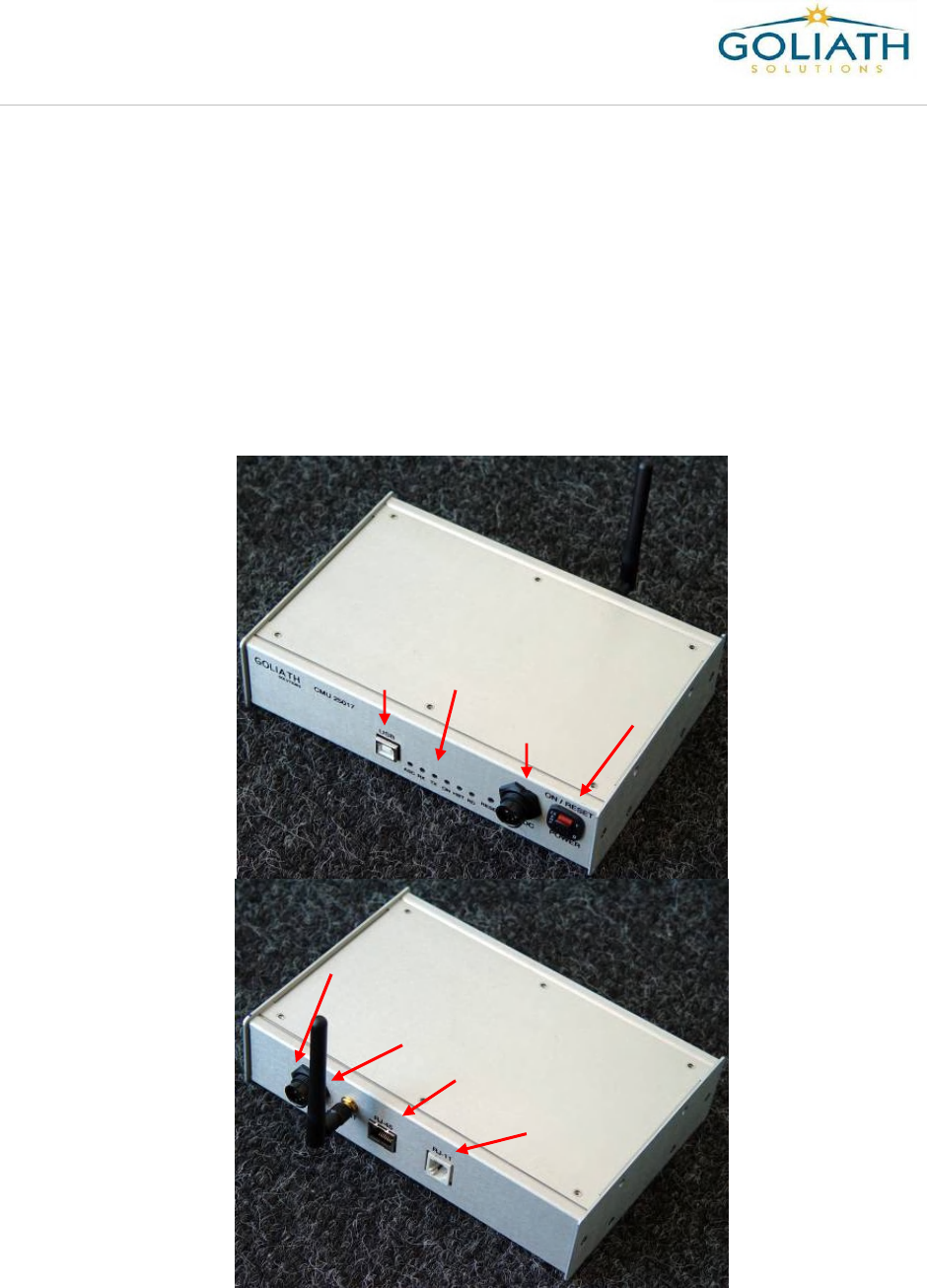
CMU (Communications Management Unit):
The CMU handles the network connectivity for the GOLIATH system. This device has an
RJ-45 port that connects to the store’s network communications infrastructure. This
device, using the provided patch cable, is connected to the store’s network switch The
CMU will be located near this router in the Communications Cabinet. The CMU
communicates with the Main Electrical Unit (MEU) wirelessly. The CMU will support either
a single or multiple MEU’s present in a store.
Power
Switch
Input for
Power
Cable
Status
Lights
USB
Port
Output for
Power
Cable
Antenna
RJ45
Port
RJ11
Port
Introduction to Store Install Processes Guide
G-1-2001-2
Introduction to Store Install Process Guide-2.doc
Use or disclosure of this document is covered under the Non-Disclosure Agreement executed between the reader and Goliath Solutions,
LLC. This document and the information contained herein are privileged and should only be viewed by expressly authorized parties.
5/27/2008 Page 3-4
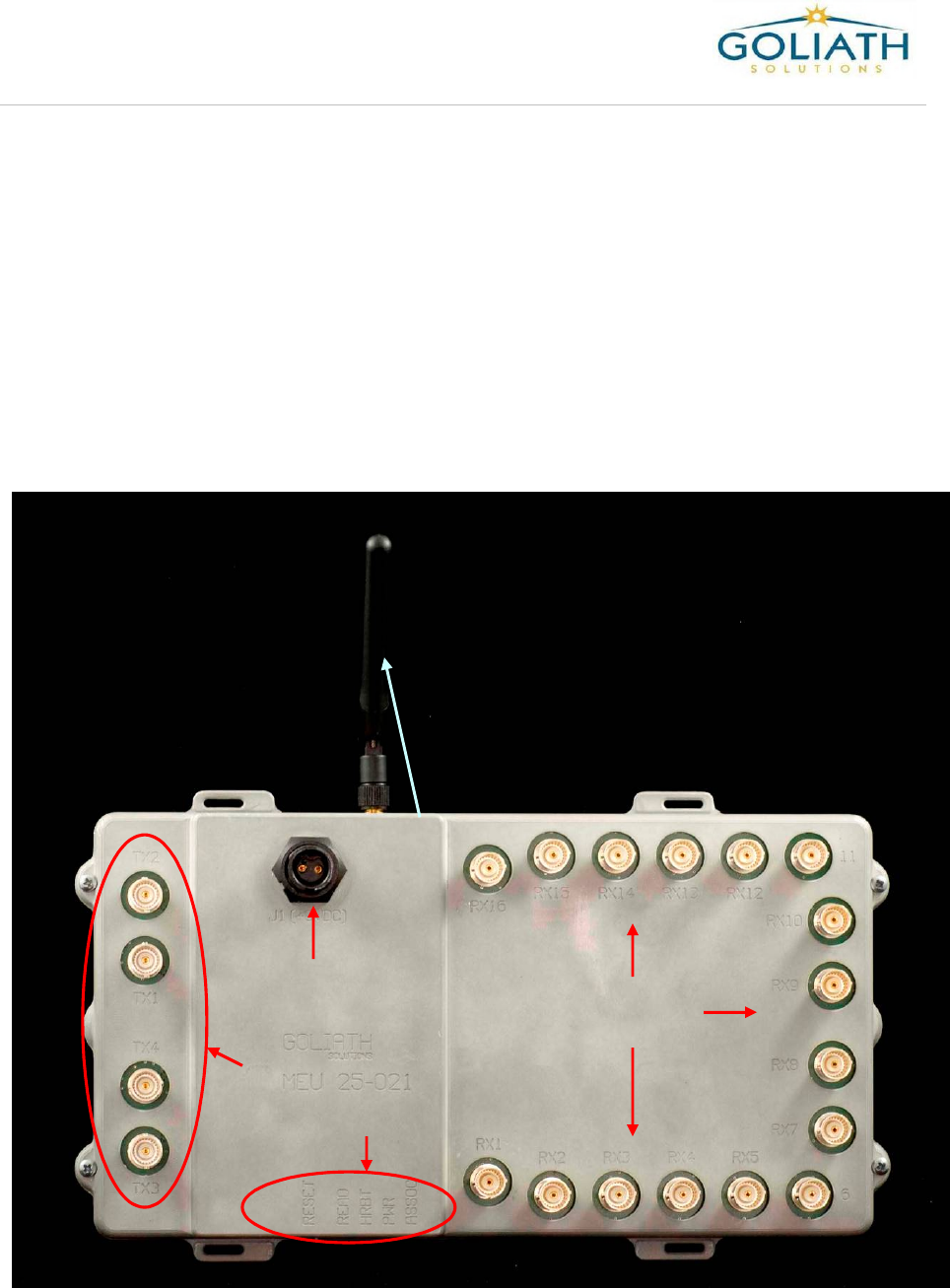
Main Electrical Unit (MEU):
The MEU is the brain or the local hub of the local GOLIATH system. It collects all system
data within the retail outlet. The MEU is normally mounted on a post near the center of
the store. Depending upon the size of the store and the Retailer’s requirements one or
more MEU’s may be required. An MEU will support up to 4 Transmitters and 16
Receivers.
The MEU is designed to communicate wirelessly with the CMU and the CMU will transfer
the captured store data to the GOLIATH Database Server. One CMU can support multiple
MEU units. Most stores will require only one MEU, but exceptions may require multiple
MEU units.
Tx Ports
Status
Lights
Input for
Power
Cable
Antenna
Rx Ports
Introduction to Store Install Processes Guide
G-1-2001-2
Introduction to Store Install Process Guide-2.doc
Use or disclosure of this document is covered under the Non-Disclosure Agreement executed between the reader and Goliath Solutions,
LLC. This document and the information contained herein are privileged and should only be viewed by expressly authorized parties.
5/27/2008 Page 3-5
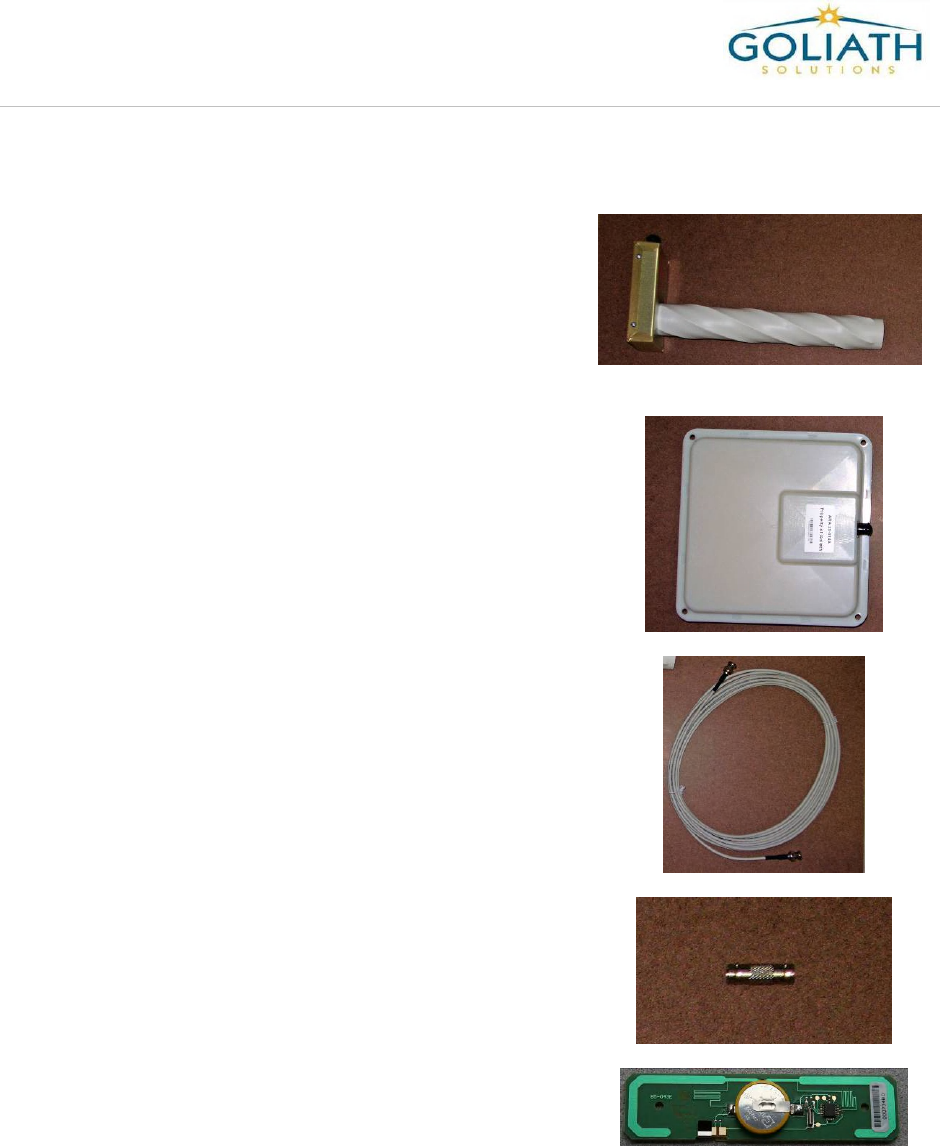
Transmitters (Tx/ATA):
These antennae amplify and “broadcast” the radio waves
that will ultimately be reflected back to the receive
antennae from the RFID tags. The number of
transmitters will vary depending on the size of the store.
Normally four transmitters is the minimum number
required to cover the entire store including the Stock
Room
Receivers (Rx/ARA):
The receive antennae “listen” for the returning radio
waves that are reflected back from the RFID tags.
Normally there are 3 to 4 receivers for each transmitter in
a store.
Coaxial Cable:
The coaxial cable runs through the roof iron and connects
the Tx/ATA and Rx/ARA antennas to the MEU. The
cables are provided in four lengths: 25 feet, 50 feet, 85
feet, and 110 feet. The cable is certified and pre-
terminated with BNC connectors and is Plenum rated.
BNC Coupler:
The BNC coupler (F to F) is used to connect two coaxial
cables together. The maximum supported cable length for
Tx/ATA’s is 110 feet and for the Rx/ARA is 135 feet.
Test Tags:
RFID Test Tags are placed throughout the store to
facilitate the testing of the GOLIATH system.
MEU I
Introduction to Store Install Processes Guide
G-1-2001-2
Introduction to Store Install Process Guide-2.doc
Use or disclosure of this document is covered under the Non-Disclosure Agreement executed between the reader and Goliath Solutions,
LLC. This document and the information contained herein are privileged and should only be viewed by expressly authorized parties.
5/27/2008 Page 3-6
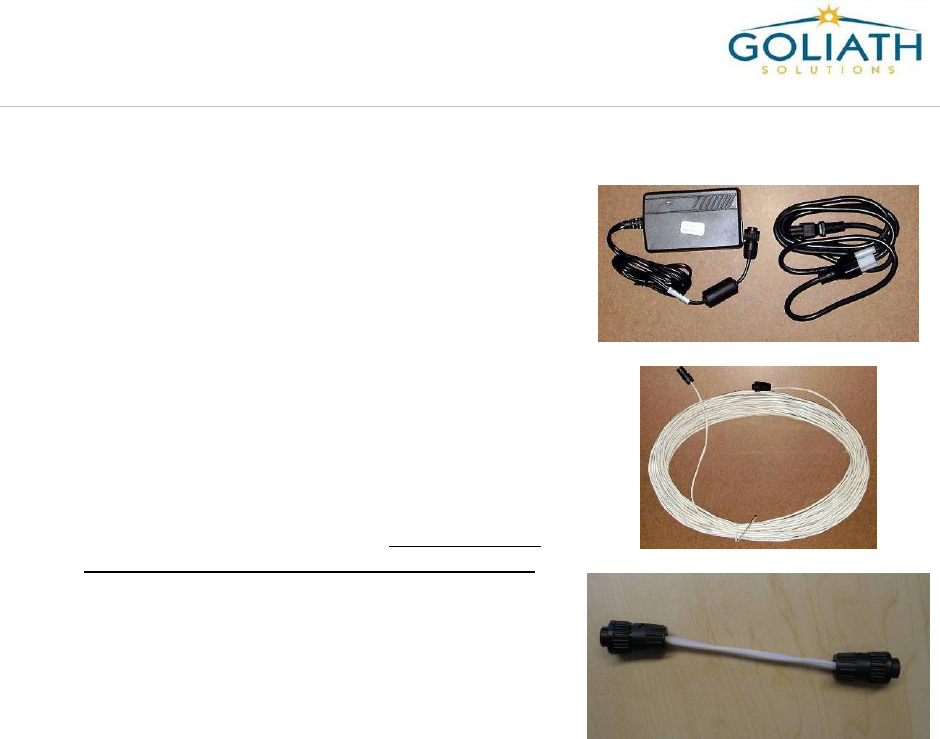
CMU/MEU Power Supply:
The power supply will be plugged into an uninterrupted
power source and provide power for the CMU or MEU.
CMU/MEU Power Cables:
Three different power cables can be used with the CMU
and MEU. The are:
1) A 110 foot low voltage power cable. This cable
is used to extend the distance from the MEU or
the CMU to the power source. The female end
of the cable will always be at the power supply.
If used with the MEU the male end must be at
the MEU.
2) A 12 foot low voltage power cable. This cable is
normally used at the CMU location if needed.
3) A Gender Changer cable. This cable is used to
connect the female end of a power cable to the
output power port on the CMU. This port has a
female connector.

Introduction to Store Install Processes Guide
G-1-2001-2
Introduction to Store Install Process Guide-2.doc
Use or disclosure of this document is covered under the Non-Disclosure Agreement executed between the reader and Goliath Solutions,
LLC. This document and the information contained herein are privileged and should only be viewed by expressly authorized parties.
5/27/2008 Page 4-1
Chapter 4 -Store Installation Procedures:
Overview of the Installation Process:
The store installation process involves the installation of the transmitters (Tx/ATA),
receivers (Rx/ARA), coaxial cables and the MEU into the ceiling of a Retail Store. The
process will also include the installation of the CMU at the communications LAN cabinet in
the store if MEU III is being installed. The exact installation requirements and processes
for each Retailer are defined in the Cable Installation Guide for that Retailer.
The following list is a summary of the Installation Steps for the Goliath Solutions System.
1) Check-in with Store Management and the Help Desk.
2) Perform a Pre-installation Survey.
3) Installation Prep.
4) Installation of the CMU.
5) Temporary installation of one or more MEU’s for communications testing.
6) Cable Pulls.
7) Installation of Transmitters.
8) Installation of Receivers.
9) Permanent installation of the MEU’s.
10) Installation Completion.
11) Site Clean-up.
12) Store Check Out.
A brief summary of each step follows in this Guide and the Retailer Specific step is defined
in the Cable Installation Guide for that Retailer.

Introduction to Store Install Processes Guide
G-1-2001-2
Introduction to Store Install Process Guide-2.doc
Use or disclosure of this document is covered under the Non-Disclosure Agreement executed between the reader and Goliath Solutions,
LLC. This document and the information contained herein are privileged and should only be viewed by expressly authorized parties.
5/27/2008 Page 4-2
Check-In:
The Store Check-In process involves the following tasks:
Introduce yourself and your installation team to the highest available level of Store
Management.
Give an overview of the installation process.
Locate the Installation Kit shipped to the store.
Call the Help Desk to check-in.
Pre-installation Survey:
The Pre-installation Survey Process has two purposes. The first is to determine if there
are any issues that could prevent the successful installation of the GOLIATH System. If
there are no issues that would prevent the installation then the survey would determine the
correct locations to install the system hardware.
Some issues that could prevent the successful installation are
Missing Installation Kit.
Incomplete Installation Kit.
Damaged Installation Kit.
Not having the correct ladders or scissor lifts to get in the ceiling.
Obstructions in ceiling.
Non-Standard ceilings.
During the Survey you will determine the permanent location for the following hardware:
Determine the most suitable location for the CMU (if applicable).
Determine the most suitable power source location for the permanent MEU
installation location.
Determine the most suitable permanent location for the MEU.
Determine the antennae location (both Tx/ATA and Rx/ARA).

Introduction to Store Install Processes Guide
G-1-2001-2
Introduction to Store Install Process Guide-2.doc
Use or disclosure of this document is covered under the Non-Disclosure Agreement executed between the reader and Goliath Solutions,
LLC. This document and the information contained herein are privileged and should only be viewed by expressly authorized parties.
5/27/2008 Page 4-3
Installation:
Installation Prep:
Unpack the Installation Kit and review its contents:
Verify you have received the correct equipment for the installation.
Once contents have been verified, begin labeling the cables for installation.
Record serial numbers for MEU and CMU.
CMU Installation:
This step will only be performed if the site is using a CMU and a MEU III. Skip this step if
you are installing an MEU I. The following steps are needed for the CMU installation.
The CMU is normally installed near the Store’s LAN cabinet. The exact location will
vary by Retailer.
The CMU/MEU power supply and cable will be plugged into an available uninterrupted
power outlet in the immediate vicinity of the CMU.
MEU Temporary Placement:
This step will only be performed if the site is using a CMU and a MEU III.
The MEU or MEU(s) will be temporarily placed and powered up within 12’ of the
location of the CMU for testing.
Cable Pulls:
Coaxial cable will be run throughout the store from the permanent location of the MEU to
the location of each one of the Tx/ATA and Rx/ARA antennas. The number of cable pulls
for a store should be minimized by combining pulls whenever possible. Perform the cable
pulls as efficiently as possible. The following standards must be followed.
All cable pulls must adhere to the Retailer Specific installation requirements.
All cables must be run through the roof girders or as required by the Retailer.
Industry cabling standards should be followed.
All equipment installed in the ceiling requires secured, self supporting service loops.
The maximum supported cable length for transmitters is 110 feet.
The maximum supported cable length of receivers is 135 feet.
If two cables are joined together an F to F BNC coupler must be used and properly
secured.
Introduction to Store Install Processes Guide
G-1-2001-2
Introduction to Store Install Process Guide-2.doc
Use or disclosure of this document is covered under the Non-Disclosure Agreement executed between the reader and Goliath Solutions,
LLC. This document and the information contained herein are privileged and should only be viewed by expressly authorized parties.
5/27/2008 Page 4-4
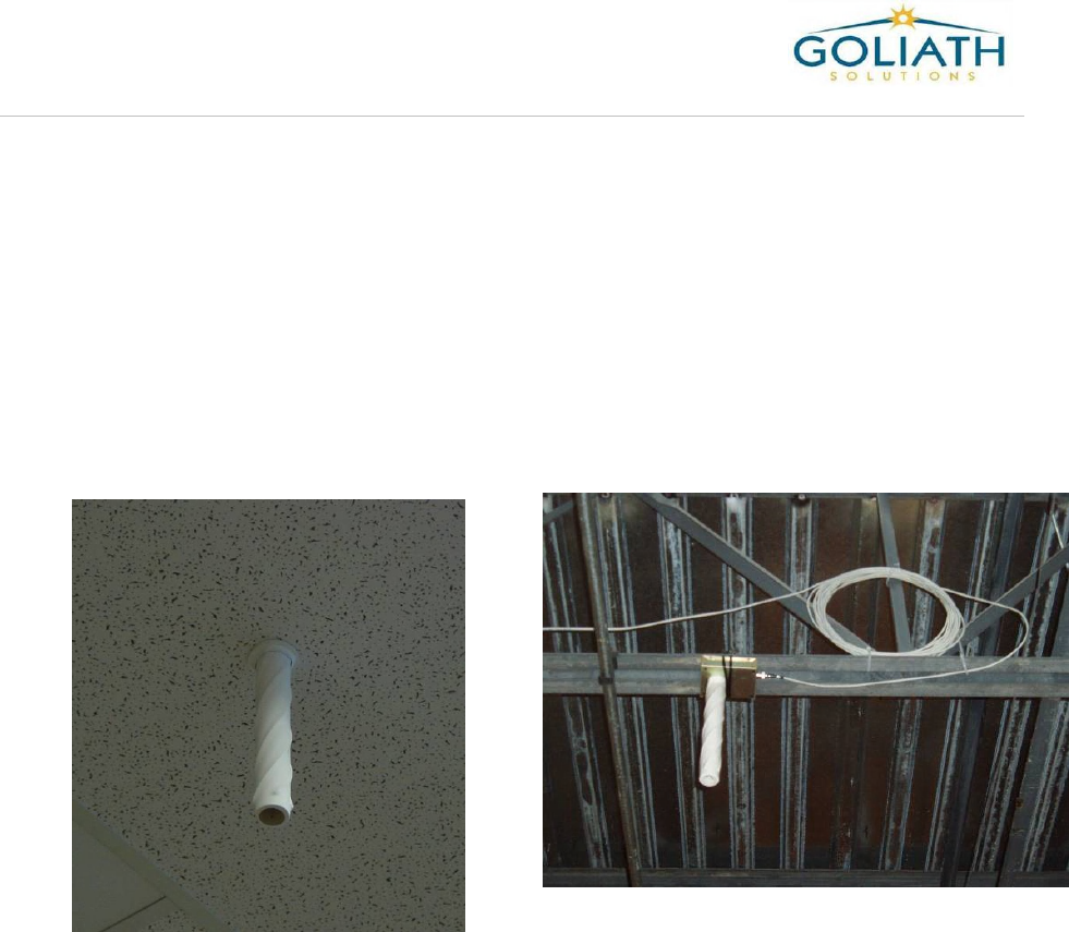
Tx/ATA Installation:
The antenna locations will be verified during the Pre-installation Survey performed by
the Lead Technician.
The location of the Tx/ATA should be placed directly over the flooring with a clean line
of sight to the floor, not over any fixtures or tables.
A minimum of 4 transmitters will be installed in the store.
The transmitter will be installed in a ceiling tile or attached to a roof girder iron or
attached directly to the roof.
The Tx/ATA must always be plumb – this may require shimming the antenna base
above the ceiling.
Tx installed in ceiling tile
Tx I
nstalled
on a
roof girder
Introduction to Store Install Processes Guide
G-1-2001-2
Introduction to Store Install Process Guide-2.doc
Use or disclosure of this document is covered under the Non-Disclosure Agreement executed between the reader and Goliath Solutions,
LLC. This document and the information contained herein are privileged and should only be viewed by expressly authorized parties.
5/27/2008 Page 4-5
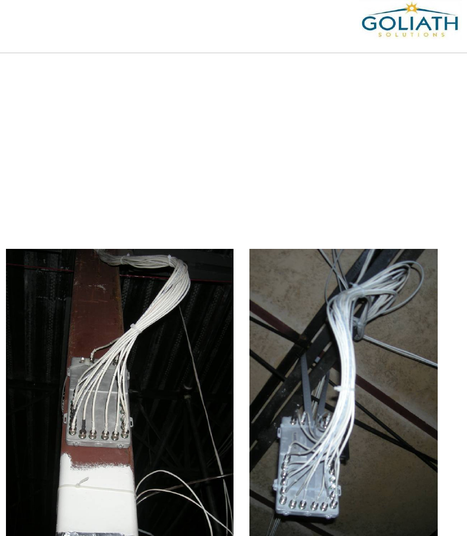
Rx/ARA Installation:
The antenna locations will be verified during the Pre-installation Survey performed by
the Lead Technician.
The location of the Rx/ARA should be placed directly over the flooring, not over any
fixtures or tables.
The number of receivers is determined by the store’s requirements; normally a
minimum of 14 receivers will be installed in the store.
The receiver will be attached on a ceiling tile or attached to a roof girder or attached
directly to the roof.
Rx Installed
in Stock Room
Rx Installed on
Ceiling Tile
R
x Installed
on a
roof girder
Rx
Installed
on
ceiling tile
Introduction to Store Install Processes Guide
G-1-2001-2
Introduction to Store Install Process Guide-2.doc
Use or disclosure of this document is covered under the Non-Disclosure Agreement executed between the reader and Goliath Solutions,
LLC. This document and the information contained herein are privileged and should only be viewed by expressly authorized parties.
5/27/2008 Page 4-6
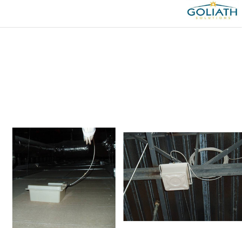
MEU Permanent Location:
An MEU I will be installed initially at its permanent location. An MEU III can be moved to
its permanent location after the Help Desk has tested it with the CMU.
The MEU will normally be mounted on a post near the center of the store or
suspended from a roof girder.
The MEU is attached to the post using one or more 36 inch cable ties.
In some Retailers you can suspend the MEU from the ceiling grid iron.
The MEU requires an uninterrupted power source that can be reached by a 110 foot
power cable. The male end of the power cable must be at the MEU location.
Suspended
Mount
MEU III
Post
Mounted
MEU III

Introduction to Store Install Processes Guide
G-1-2001-2
Introduction to Store Install Process Guide-2.doc
Use or disclosure of this document is covered under the Non-Disclosure Agreement executed between the reader and Goliath Solutions,
LLC. This document and the information contained herein are privileged and should only be viewed by expressly authorized parties.
5/27/2008 Page 4-7
Installation Completion:
After the completion of the installation of the GOLIATH hardware in the store the following
tasks still must be completed:
Verify that all cables are securely connected to the MEU at their corresponding ports.
After all the antennas are connected to the MEU, connect the power to the MEU and
verify that the Green power indicator is on.
Site Clean-up:
Inspect the entire store, including the Stock Room, for any installation debris left by the
Crew.
If the location of the equipment was marked on the floor, remove the painters tape.
If there is a drop down ceiling verify all ceiling tiles are back in place and seated
properly.
If there is a drop down ceiling remove any debris from the drop-ceiling around the
MEU.
Dispose of the installation debris and trash.
Store Check-out:
You can check-out with the store management and the Help Desk after the following tasks
have been completed.
Completion of the System Test
Replace the ceiling tile at the MEU.
Gather all remaining installation equipment and remove it from the store.
Any OBF equipment should be boxed up with the return label and then sent to Goliath
Solutions.
Quality Assurance Survey (QA):
A QA Survey will be performed by GOLIATH personnel sometime after the installation.
The purpose of this visit is to verify that the CIV has completed the installation in
accordance with the standards and Best Practices specified in the agreed upon RFP and
this document.