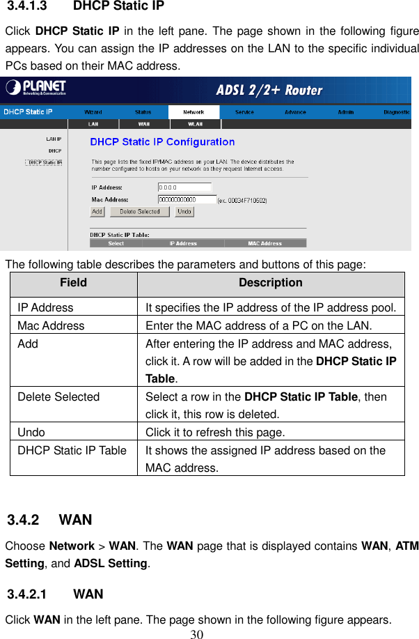
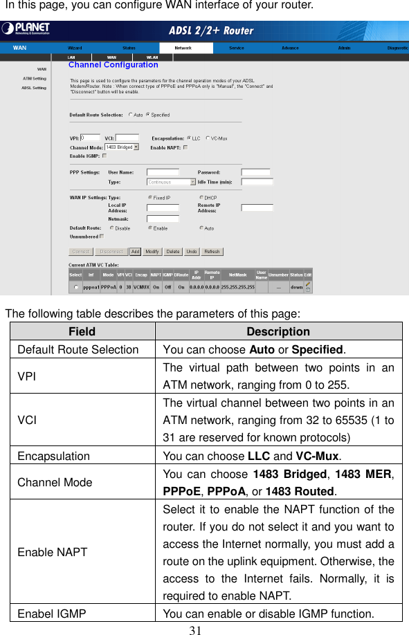
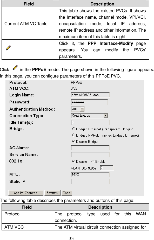
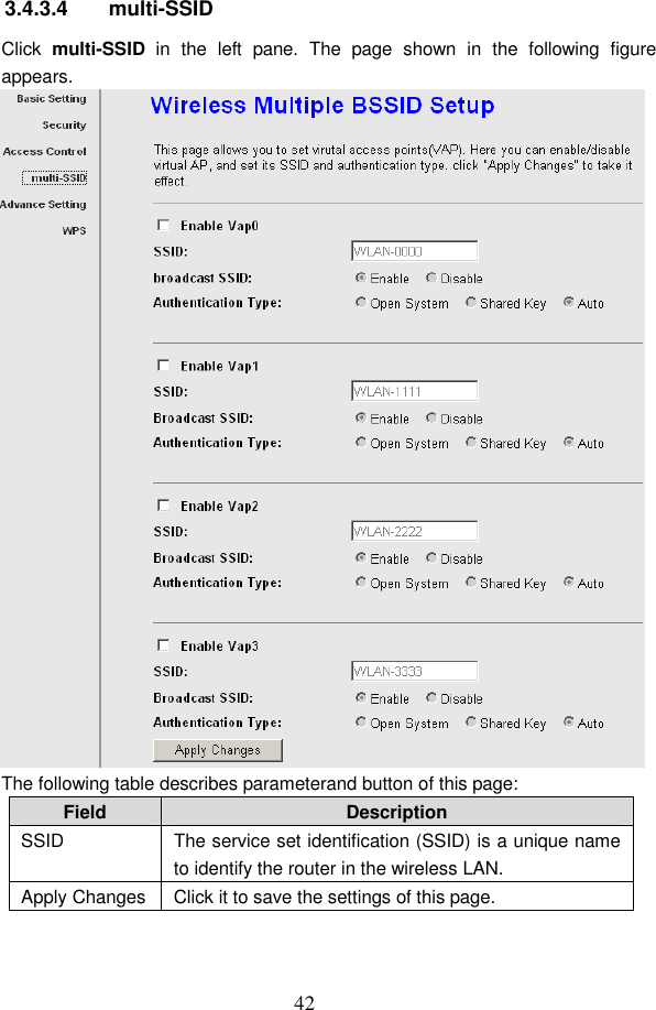
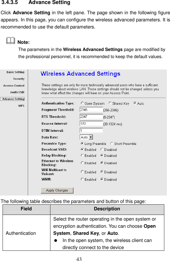
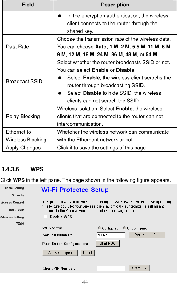
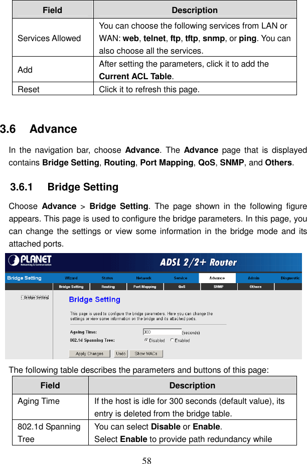
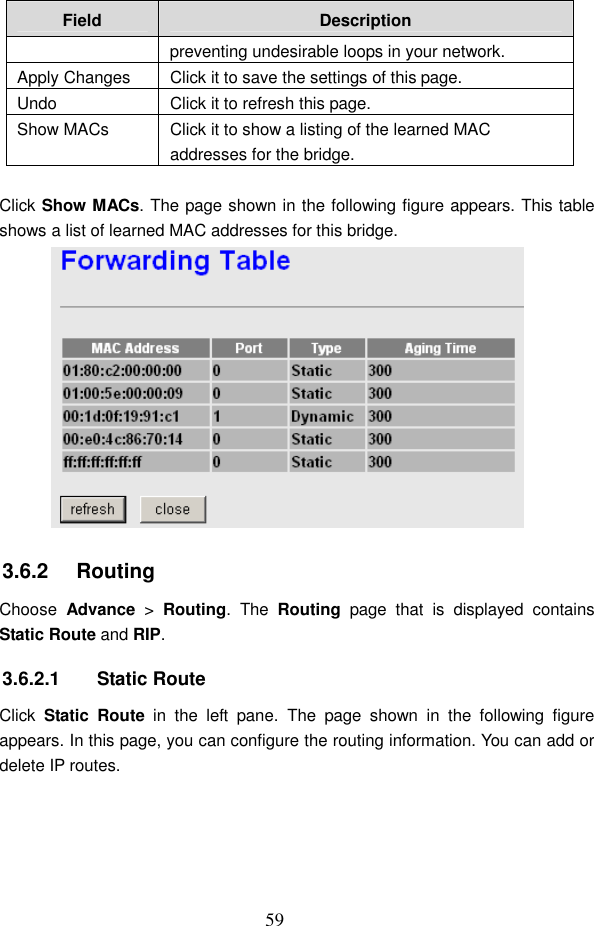
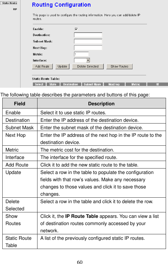
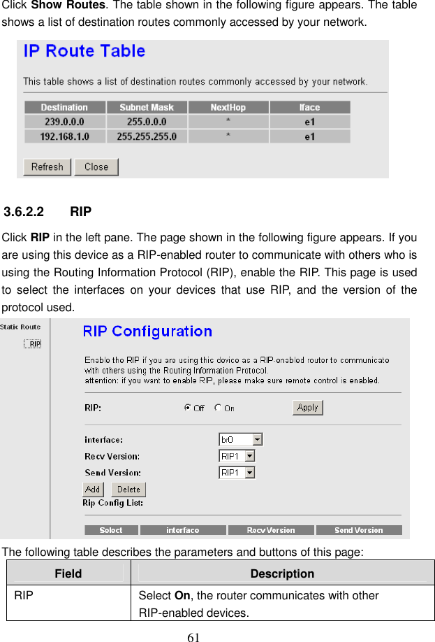
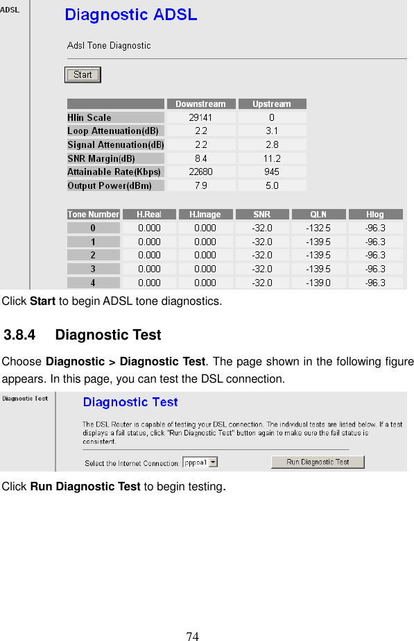
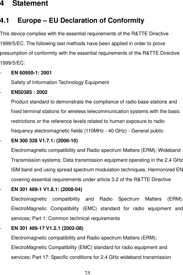
Gongjin Electronics GAW95Z97-4 802.11b/g Wireless ADSL 2/2+ Router User Manual Gaw9 5Z97 4 v 1

Shenzhen Gongjin Electronics Co., Ltd 802.11b/g Wireless ADSL 2/2+ Router Gaw9 5Z97 4 v 1

User Manual

           Gaw9.5Z97-4 User Manual
 i Contents 1 Introduction..................................................................................................... 1 1.1 Safety Precautions.............................................................................. 1 1.2 LEDs and Interfaces............................................................................ 2 1.3 System Requirements......................................................................... 4 1.4 Features..............................................................................................4 1.5 Supported Protocols............................................................................ 5 2 Hardware Installation ...................................................................................... 6 3 About the Web Configuration.......................................................................... 9 3.1 How to Access the Router ................................................................... 9 3.2 Wizard............................................................................................... 10 3.3 Status................................................................................................ 19 3.3.1 System ................................................................................... 19 3.3.2 LAN ........................................................................................ 20 3.3.3 WLAN..................................................................................... 20 3.3.4 WAN....................................................................................... 21 3.3.5 Port Mapping .......................................................................... 22 3.3.6 Statistics ................................................................................. 22 3.3.7 ARP Table............................................................................... 24 3.4 Network............................................................................................. 24 3.4.1 LAN ........................................................................................ 25 3.4.2 WAN....................................................................................... 30 3.4.3 WLAN..................................................................................... 36 3.5 Service.............................................................................................. 45 3.5.1 DNS........................................................................................ 45 3.5.2 Firewall................................................................................... 47 3.5.3 UPNP ..................................................................................... 53 3.5.4 IGMP Proxy ............................................................................ 54 3.5.5 TR069..................................................................................... 54 3.5.6 ACL ........................................................................................ 57 3.6 Advance............................................................................................ 58 3.6.1 Bridge Setting......................................................................... 58 3.6.2 Routing................................................................................... 59 3.6.3 Port Mapping .......................................................................... 62
ii 3.6.4 QoS........................................................................................ 64 3.6.5 SNMP..................................................................................... 65 3.6.6 Others..................................................................................... 66 3.7 Admin................................................................................................ 67 3.7.1 Commit/Reboot....................................................................... 67 3.7.2 Upgrade.................................................................................. 68 3.7.3 System Log............................................................................. 69 3.7.4 Password................................................................................ 70 3.7.5 Time Zone .............................................................................. 71 3.8 Diagnostic ......................................................................................... 72 3.8.1 Ping........................................................................................ 72 3.8.2 ATM Loopback........................................................................ 73 3.8.3 ADSL...................................................................................... 73 4            Statement .................................................................................................. 75   4.1        Europe - EU Declaration of Conformity Statement............................. 75   4.2        Federal Communication Commission Intererence Statement ............ 77   4.3        Part 68 statement.............................................................................. 79
 1 1   Introduction The ADSL Router supports multiple line modes. It provides four 10/100 base-T Ethernet  interfaces  at  the  user  end.  The  device  provides  high-speed  ADSL broadband connection to the Internet or Intranet for high-end users, such as net bars  and  office  users.  The  device  provides  high  performance  access  to  the Internet, downlink up to 24 Mbps and uplink up to 1 Mbps. The device supports WLAN access, as WLAN AP or WLAN router, to the Internet. It  complies  with  IEEE  802.11,  802.11b/g  specifications,  and  WEP,  WPA  and WPA2 security specifications. 1.1   Safety Precautions Follow the  following instructions  to  prevent the device from  risks and damage caused by fire or electric power:   Use volume labels to mark the type of power.   Use the power adapter packed within the device package.   Pay  attention  to  the  power  load  of  the  outlet  or  prolonged  lines.  An overburden power outlet or damaged lines and plugs may cause electric shock  or fire  accident.  Check the  power  cords  regularly.  If  you find  any damage, replace it at once.   Proper space left for heat dissipation is necessary to avoid damage caused by overheating to the device. The long and thin holes on the device are designed for heat dissipation to ensure that the device works normally. Do not cover these heat dissipation holes.   Do not put this device close to a place where a heat source exits or high temperature occurs. Avoid the device from direct sunshine.   Do not put this device close to a place where it is over damp or watery. Do not spill any fluid on this device.   Do not connect this device to any PCs or electronic products, unless our customer  engineer  or  your  broadband  provider  instructs  you  to  do  this, because any wrong connection may cause power or fire risk.   Do not place this device on an unstable surface or support.
2 1.2   LEDs and Interfaces Front Panel   The following table describes the LEDs of the device: LEDs  Color Status  Description On  The device is powered on. Green Off  The device is powered off. PWR Red  On  The device is self-testing or self-testing is failed, or the software is upgrading. On  The device has established connection with the office physical layer. Blinks (fast) The  device  is  handshaking  with  the office physical layer. Link  Green Blinks (slow) The device does not detect the signals. On The  device  has  a  successful  Internet connection in the routing mode, and no data is being transmitted. Blinks  Data  is  being  transmitted  on  the Internet in the routing mode. Green Off  The device is in bridge mode. Data Red  On After  the  successful  synchronous  in the  routing  mode,  the  Internet connection is failed. On  The  device  has  successful  LAN connection. Blinks Data  is  being  transmitted  on  LAN  or data  is  being  transmitted  on  the Internet in the bridge mode. LAN4-1  Green Off  The LAN connection is failed.
3 LEDs  Color Status  Description On  The  device  has  successful  WLAN connection. Blinks  Data is being transmitted on WLAN. WLAN  Green Off  The WLAN connection is failed. Off  WPS is disabled. WPS  Green Blinks  WPS  is  enabled,  and  is  waiting  for client to negotiate.  Rear Panel   The following table describes the interfaces of the device: Interface Description  Wireless antenna. Line  RJ-11  interface,  for  connecting  to  the  ADSL  interface  or  a splitter through a telephone cable. LAN1/LAN2/LAN3/LAN4 RJ-45  interface,  for connecting  to  the  Ethernet interface  of the PC or the Ethernet devices through an Ethernet cable. Power  Power interface, for connecting to the power adapter of 12 V DC, 1 A. Reset Reset to the factory defaults. To restore factory defaults, keep the device powered on and push a paper clip into the hole. Press down the button 3 seconds and then release. WPS/WLAN   Press the button silently less than 1 second to enable WLAN function.   Press the button for more than 3 seconds (include 3 seconds) to enable to enable WPS function.   If you press the button between 1 second and 3 seconds, no function takes effective.
4 Interface Description ON/OFF  Power switch, power on or power off the router.  1.3   System Requirements Recommended system requirements are as follows:   A 10/100 base-T Ethernet card is installed on your PC   A hub or Switch. (attached to several PCs through one of Ethernet interfaces on the device)   Operating system: Windows 98SE, Windows 2000, Windows ME, Windows XP or Windows Vista   Internet Explorer V5.0 or higher, Netscape V4.0 or higher, or firefox 1.5 or higher 1.4   Features The device supports the following features:   Various line modes (line auto-negotiation)   External PPPoE dial-up access   Internal PPPoE/PPPoA dial-up access   Zero installation PPP bridge mode (ZIPB)   1483B/1483R/MER access   Multiple PVCs (eight at most)   A single PVC with multiple sessions   Multiple PVCs with multiple sessions   DHCP server   NAT/NAPT   Static route   Firmware upgrading through Web, TFTP, or FTP   Rsetting to the factory defaults through Reset button or Web   DNS relay   Virtual server   Web interface   Telnet CLI   System status display
5   PPP session PAP/CHAP   IP/Port, MAC, URL filter   Remote access control   Line connection status test   Remote access control   Backup and restoration of configuration file   IP quality of service (QoS)   Universal plug and play (UPnP)   WLAN with high-speed data transmission rate, up to 54 Mbps, compatible with IEEE 802.11b/g, 2.4 GHz compliant equipment 1.5   Supported Protocols The device supports the following protocols:   ITU G.992.1 (G.DMT) Annex A   ITU G.992.2 (G.LITE)   ANSI T1.413 Issue 2   ITU G.992.3 (ADSL2)   ITU G.992.5 (ADSL2+)   Annex L   Annex M
 6 2   Hardware Installation Step 1  Connect the Line interface of the device and the Modem interface of the  splitter  through  a  telephone  cable.  Connect  the  phone  to  the Phone interface of the splitter through a cable. Connect the incoming line to the Line interface of the splitter. The splitter has three interfaces:  Line: Connect to a wall phone jack (RJ-11 jack)  Modem: Connect to the ADSL jack of the device  Phone: Connect to a telephone set. Step 2  Connect the Ethernet interface of the device to the network card of the PC through an Ethernet cable (MDI/MDIX). I    Note: Use twisted-pair cables to connect with the hub or switch. Step 3  Plug one end of the power adapter to the wall outlet and connect the other end to the Power interface of the device. Connection 1 錯誤錯誤錯誤錯誤!  找不到參照來源找不到參照來源找不到參照來源找不到參照來源。。。。  displays the application diagram for the connection of the router, PC, splitter and the telephone sets, when no telephone set is placed before the splitter.
 7  Figure 1 Connection diagram (Without connecting telephone sets before the splitter) Connection 2 Figure 2 shows the connection when the splitter is installed close to the router.  Figure 2 Connection diagram (Connecting a telephone set before the splitter)     Note: When connection 2 is used, the filter must be installed close to the telephone cable. See Figure2. Do not use the splitter to replace the filter. Installing a telephone directly before the splitter may lead to failure of connection between the device and the central office, or failure of Internet access, or slow connection speed. If you really need to add a telephone set before the splitter,
 8 you  must  add  a  microfilter  before  a  telephone  set.  Do  not  connect  several telephones before the splitter or connect several telephones with the microfilter. Wall Mount Diagram The device can be mounted on the wall. Figure 3 shows the wall mount diagram.  Figure 3 Wall mount diagram
 9 3   About the Web Configuration This  chapter  describes  how  to  configure  the  router  by  using  the  Web-based configuration utility. 3.1   How to Access the Router The following is the detailed description of accesing the router for the first time. Step 1  Open the Internet Explorer (IE) browser and enter http://192.168.1.1. Step 2  In  the  LOGIN  page  that  is  displayed,  enter  the  username  and password.   The username and password of the super user are admin and admin respectively.   The user name and password of the common user are user and user respectively.  If you log in as the super user, the page shown in the following figure appears.
 10  If you log in as a common user, you can check the status of the router, but can not configure the most of the settings. 3.2   Wizard When subscribing to a broadband service, you should be aware of the method by which you are connected to the Internet. Your physical WAN device can be either PPP,  ADSL,  or  both.  The  technical  information  about  the  properties  of  your Internet  connection  is  provided  by  your  Internet  Service  Provider  (ISP).  For example, your ISP should inform you whether you are connected to the Internet using  a  static  or  dynamic  IP  address,  and  the  protocol  that  you  use  to communicate on the Internet. In the  navigation  bar, choose Wizard. The page shown in the  following figure appears. The Wizard page guides fast and accurate configuration of the Internet connection  and  other  important  parameters.  The  following  sections  describe these  various  configuration  parameters.  Whether  you  configure  these parameters  or  use  the  default  ones,  click  NEXT  to  enable  your  Internet connection.
 11  Enter  the  correct  password  and  then  click  NEXT.  The  page  shown  in  the following figure appears. In this page, you can set the system time and Network Time Protocol (NTP) server.  The following table describes the parameters of this page: Field  Description State You can disable or enable NTP function. You have to enable it if you want to configure the parameters in this page. Server IP  Enter the IP address of the specified time server manually.
 12 Field  Description Interval Set the interval that the router obtains the time from the time server. That is, the interval that the router verifies the time with the server. Time Zone  Choose the time zone of your country. GMT time  It displays the Greenwich mean time.  After finishing the  configuration, click NEXT. The  page shown in the following figure appears.  The following table describes the parameters of this page: Field  Description PVC Settings   The virtual path between two points in an ATM network, and its valid value is from 0 to 255.   The virtual channel between two points in an ATM network, ranging from 32 to 65535 (0 to 31 is reserved for local management of ATM traffic). Encapsulation Select the method of encapsulation provided by your
 13 Field  Description ISP. You can select LLC/SNAP or VC-Mux. Channel Mode Select the WAN connection type. You can select 1483 Bridged, 1483 MER, PPP over Ethernet (PPPoE), PPP over ATM (PPPoA), or 1483 Routed. PPP Settings The username and password apply to PPPoE and PPPoA encapsulation only. Ensure that you enter the correct username and password. Default Route You can select Enable or Disable. DNS Settings  Obtain DNS Automatically: Obtain the DNS server assigned by the uplink equipment, such as BAS.  Use the following DNS server address: If you want to enter the DNS server address by yourself, select it and enter the related data.  After finishing the  configuration, click NEXT. The  page shown in the following figure appears.  The following table describes the parameters of this page: Field  Description WLAN Interface You can choose Enable or Disable. By default, WAN interface is enabled. You need to enable WAN interface, and then you can
 14 Field  Description set the parameters in this page. Band Choose the working mode of the router. You can choose 2.4 GHz (B), 2.4 GHz (G), or 2.4 GHz (B + G). By defaut, the band is 2.4 GHz (B + G). SSID The service set identification (SSID) is a unique name to identify the router in the wireless LAN. Wireless stations associating to the router must have the same SSID. Enter a descriptive name that is used when the wireless client connecting to the router. Encryption Configure the wireless encryption mode. You can choose None, WEP, WPA (TKIP), WPA (AES), WPA2 (AES), WPA2 (TKIP), or WPA2 Mixed.   Wired equivalent privacy (WEP) encrypts data frames before transmitting over the wireless network.   Wi-Fi protected access (WPA) is a subset of the IEEE802.11i security specification draft.    WPA2 Mixed is the collection of WPA and WPA2 encryption modes. The wireless client establishes the connection between the router through WPA or WPA2. Key differences between WPA and WEP are user authentication and improved data encryption.  After finishing the  configuration, click NEXT. The  page shown in the following figure appears.
 15  1483 Bridged  In the Setup WAN Interface page, set the channel mode to 1483 Bridged 1483 MER
 16  In the Setup WAN Interface page, set the channel mode to 1483 MER PPPoE
 17  In the Setup WAN Interface page, set the channel mode to PPPoE PPPoA
 18  In the Setup WAN Interface page, set the channel mode to PPPoA 1483 Routed
 19  In the Setup WAN Interface page, set the channel mode to 1483 Routed 3.3   Status In  the  navigation  bar,  choose  Status. In  the  Status  page  that  is  displayed contains: System, LAN, WLAN, WAN, Port Mapping, Statistic, and ARP Table. 3.3.1   System Choose Status > System. The page that is displayed shows the current status and some basic settings of the router, such as software version, DSP version, uptime, upstream speed, and downstream speed.
 20  3.3.2   LAN Choose  Status  >  LAN.  The  page  that  is  displayed  shows  some  basic  LAN settings  of  the  router.  In  this  page,  you can  view the  LAN  IP address,  DHCP server status, MAC address, and DHCP client table. If you want to configure the LAN network, refer to chapter 3.4.1.1 LAN IP.  3.3.3   WLAN Choose Status > WLAN. The page that is displayed shows some basic WLAN settings of the router. In this page, you can view basic status of WAN and DNS server. If you want to configure the WAN network, refer to chapter 3.4.3 .
 21  3.3.4   WAN Choose  Status  >  WAN.  The  page that  is  displayed  shows  some  basic  WAN settings of the router. In this page, you can view basic status of WAN and DNS server. If you want to configure the WAN network, refer to chapter 3.4.2.1 WAN.
 22 3.3.5   Port Mapping Choose Status > Port Mapping. In this page, you can view the mapping relation and the status of port mapping.  3.3.6   Statistics Choose  Status  >  Statistics.  The  Statistics  page  that  is  displayed  contains Traffic Statistic and DSL Statistic. 3.3.6.1  Traffic Statistic Click Traffic Statistic in the left pane. The page shown  in the following figure appears. In this page, you can view the statistics of each network port.
 23  3.3.6.2  DSL Statistic Click  DSL  Statistic  in  the  left  pane.  The  page  shown  in  the  following  figure appears.  In  this  page,  you  can  view  the  ADSL  line  status,  upstream  rate, downstream rate, and other information.
 24  3.3.7   ARP Table Choose Status > ARP Table. In the ARP Table page, you can view the table that shows a list of learned MAC addresses.  3.4   Network In  the  navigation  bar,  choose  Network. The  Network  page  that  is  displayed contains LAN, WAN, and WLAN.
 25 3.4.1   LAN Choose  Network  >  LAN.  The  LAN  page  that  is  displayed  contains  LAN  IP, DHCP, and DHCP Static IP. 3.4.1.1  LAN IP Click LAN IP in the left pane. The page shown in the following figure appears. In this page, you can change IP address of the router. The default IP address is 192.168.1.1.  This  is  the  private  IP  address  of  the  router.  This  is  the  address under  which  the  router  can  be  reached  in  the  local  network.  It  can  be  freely assigned from the block of available addresses.  The following table describes the parameters and button of this page: Field  Description IP Address Enter the IP of LAN interface. It is recommended to use  an address  from a  block  that  is  reserved for private  use.  This  address  block  is  192.168.1.1- 192.168.255.254. Subnet Mask Enter the subnet mask of LAN interface. The range of  subnet  mask  is  from 255.255.0.0-255.255.255.254. Secondary IP  Select it to enable the secondary LAN IP. The two LAN IP addresses must be in the different network. IGMP Snooping  You can disable or enable IGMP Snooping. Apply Changes  Click it to save the settings of this page.
 26  3.4.1.2  DHCP Dynamic Host Configuration Protocol (DHCP) allows the individual PC to obain the TCP/IP configuration from the centralized DHCP server. You can configure this  router  as  a  DHCP  server  or  disable  it.  The  DHCP  server  can  assign  IP address, IP default gateway, and DNS server to DHCP clients. This router can also act as a surrogate DHCP server (DHCP proxy) where it relays IP address assignment  from  an  actual  real  DHCP  server  to  clients.  You  can  enable  or disable DHCP server or DHCP proxy. Click DHCP in the left pane. The page shown in the following figure appears.  The following table describes the parameters in this page: Field  Description DHCP Mode If set to DHCP Server, the router can assign IP addresses, IP default gateway and DNS Servers to Windows95, Windows NT and other systems that support the DHCP client. IP Pool Range  It specifies the first and the last of contiguous IP address of the IP address pool.
 27 Field  Description Show Client  Click it, the Active DHCP Client Table page appears. It shows the assigned IP address of the clients. Default Gateway Enter the IP default gateway of the IP address pool. Max Lease Time The lease time determines the period that the PCs retain the assigned IP addresses before the IP addresses change. Domain Name Enter the domain name if you know. If you leave this blank, the domain name obtained by DHCP from the ISP is used. You must enter host name (system name) on each individual PC. The domain name can be assigned from the router through the DHCP server. Set VendorClass IP Range Click it, the Device IP Range Table page appears. You can configure the IP address range based on device type.  Click Show Client in the DHCP Settings page. The page shown in the following figure appears. You can view the IP address assigned to each DHCP client.  The following table describes the parameters and buttons in this page: Field  Description IP Address  It displays the IP address relative to the MAC address. MAC Address It displays the MAC address of the PC. Each Ethernet device has a unique MAC address. The MAC address is assigned at the factory and it consists of six pairs of hexadecimal character, for
 28 Field  Description example, 00-A0-C5-00-02-12. Expired (s) It displays the lease time. The lease time determines the period that the PCs retain the assigned IP addresses before the IP addresses change. Refresh  Click it to refresh this page. Close  Click it to close this page.  Click Set VendorClass IP Range in the DHCP Settings page. The page shown in the following figure appears. You can configure the IP address range based on device type.  Choose  None  in  the  DHCP  Settings  page.  The  page  shown  in  the  following figure appears.
 29  Choose DHCP Relay in the DHCP Mode page. The page shown in the following figure appears.  The following table describes the parameters of this page: Field  Description DHCP Mode If set to DHCP Relay, the router acts a surrogate DHCP Server and relays the DHCP requests and reponses between the remote server and the client. Relay Server  Enter the DHCP server address provided by your ISP.
 30 3.4.1.3  DHCP Static IP Click DHCP Static IP in the left pane. The page shown  in the following figure appears. You can assign the IP addresses on the LAN to the specific individual PCs based on their MAC address.  The following table describes the parameters and buttons of this page: Field  Description IP Address  It specifies the IP address of the IP address pool. Mac Address  Enter the MAC address of a PC on the LAN. Add  After entering the IP address and MAC address, click it. A row will be added in the DHCP Static IP Table. Delete Selected  Select a row in the DHCP Static IP Table, then click it, this row is deleted. Undo  Click it to refresh this page. DHCP Static IP Table It shows the assigned IP address based on the MAC address.  3.4.2   WAN Choose Network > WAN. The WAN page that is displayed contains WAN, ATM Setting, and ADSL Setting. 3.4.2.1  WAN Click WAN in the left pane. The page shown in the following figure appears.
 31 In this page, you can configure WAN interface of your router.  The following table describes the parameters of this page: Field  Description Default Route Selection  You can choose Auto or Specified. VPI  The  virtual  path  between  two  points  in  an ATM network, ranging from 0 to 255. VCI The virtual channel between two points in an ATM network, ranging from 32 to 65535 (1 to 31 are reserved for known protocols) Encapsulation  You can choose LLC and VC-Mux. Channel Mode  You can choose 1483 Bridged, 1483 MER, PPPoE, PPPoA, or 1483 Routed. Enable NAPT Select it to enable the NAPT function of the router. If you do not select it and you want to access the Internet normally, you must add a route on the uplink equipment. Otherwise, the access  to  the  Internet  fails.  Normally,  it  is required to enable NAPT. Enabel IGMP  You can enable or disable IGMP function.
 32 Field  Description PPP Settings   User Name  The  correct  user  name  that  your  ISP  has provided to you. Password  The  correct  password  that  your  ISP  has provided to you. Type  You  can  choose  Continuous,  Connect  on Demand, or Manual. Idle Time (min) If  select  connect  on  demand,  you  need  to enter the idle timeout time. Within the preset minutes, if the router does not detect the flow of  the  user  continuously,  the  router automatically  disconnects  the  PPPoE connection. WAN IP Settings   Type You can choose Fixed IP or DHCP. If select fixed  IP,  you  should  enter  the  local  IP address,  remote  IP  address  and  subnet mask.  If  set  to  use  DHCP,  the  router  is  a DHCP  client,  the  WAN  IP  address  is assigned by the remote DHCP server. Local IP Address  It is the IP address of WAN interface that is provided by your ISP. Remote IP Address  This  is  the  gateway  IP  address  that  is provided by your ISP. Netmask  It is the subnet mask of the local IP address. Unnumbered  Select  this  checkbox  to  enable  IP Unnumbered function.   Add After configuring the parameters of this page, click it to add a new PVC into the current ATM VC table. Modify Select  a PVC  in  the current ATM  VC  table, then modify the parameters of this PVC. After finishing, click it to  apply the change of  this PVC.
 33 Field  Description Current ATM VC Table This table shows the existed PVCs. It shows the Interface name, channel mode, VPI/VCI, encapsulation  mode,  local  IP  address, remote IP address and other information. The maximum item of this table is eight.  Click  it,  the  PPP  Interface-Modify  page appears.  You  can  modify  the  PVCs’ parameters.  Click  in the PPPoE mode. The page shown in the following figure appears. In this page, you can configure parameters of this PPPoE PVC.  The following table describes the parameters and buttons of this page: Field  Description Protocol  The  protocol  type  used  for  this  WAN connection. ATM VCC  The ATM virtual circuit connection assigned for
 34 Field  Description this PPP interface (VPI/VCI). Login Name  The login name provided by your ISP. Password  The password provided by your ISP. Authentication Method You can choose AUTO, CHAP, or PAP. Connection Type  You  can  choose  Continuous,  Connect  on Demand, or Manual. Idle Time (s)  If  choose  Connect on  Demand, you  need  to enter  the  idle  timeout  time.  Within  the  preset minutes, if the router does not detect the flow of the user continuously, the router automatically disconnects the PPPoE connection. Bridge  You  can  choose  Bridged  Ethernet,  Bridged PPPoE, or Disable Bridge. AC-Name  The accessed equipment type. Service-Name  The service name. Apply Changes  Click it to save the settings of this page. Return  Click it to return to the WAN Interface page. Undo  Click it to refresh this page.  3.4.2.2  ATM Setting Click  ATM  Setting  in  the  left  pane.  The  page  shown  in  the  following  figure appears. In this page, you can configure the parameters of the ATM, including QoS, PCR, CDVT, SCR, and MBS
 35  The following table describes the parameters and buttons of this page: Field  Description VPI  The virtual path identifier of the ATM PVC. VCI  The virtual channel identifier of the ATM PVC. QoS  The QoS category of the PVC. You can choose UBR, CBR, rt-VBR, or nrt-VBR. PCR  The  maximum  rate  at  which  cells  can  be transported  along  a  connection  in  the  ATM network. CDVT  The  amount  of  delay  permitted  between  ATM cells (expressed in microseconds). SCR  The  maximum  rate  that  traffic  can  pass  over  a PVC without the risk of cell loss. MBS  The  maximum  number  of  cells  that  can  be transmitted at the PCR. Apply Changes  Click it to save the settings of this page. Undo  Click it to refresh this page.  3.4.2.3  ADSL Setting Click  ADSL  Setting  in  the  left  pane.  The  page  shown  in  the  following  figure appears.
 36 In this pae, you can select the DSL modulation. Mostly, you need to remain this factory default settings. The  router supports these modulations: G.lite, G.Dmt, T1.413,  ADSL2,  ADSL2+,  AnnexL,  and  AnnexM.  The  router  negotiates  the modulation modes with the DSLAM.  3.4.3   WLAN Choose Network > WLAN. In the WLAN page that is displayed contains Basic Setting, Security, Access Control, multi-SSID, Advance Setting, and WPS. 3.4.3.1  Basic Setting Click  Basic  Setting  in  the  left  pane.  The  page  shown  in  the  following  figure appears. In this page, you can configure the parameters for wireless LAN clients that may connect to the router.
 37  The following table describes the parameters and buttons of this page: Field  Description Band Choose the working mode of the router. You can choose 2.4 GHz (B), 2.4 GHz (G), or 2.4 GHz (B + G). By defaut, the band is 2.4 GHz (B + G). Mode Choose the network modle of the router, which is varied according to the software. By defaut, the network model of the router is AP. SSID The service set identification (SSID) is a unique name to identify the router in the wireless LAN. Wireless stations associating to the router must have the same SSID. Enter a descriptive name that is used when the wireless client connecting to the router. Channel Number A channel is the radio frequency used by 802.11b/g wireless devices. You may have a choice of channels (for your region) and you should use a different channel from an adjacent AP to reduce the interference. Interference and degrading performance occurs when radio signal from different APs overlap.
 38 Field  Description Choose a channel from the drop-down list box.  Radio Power (Percent) You can choose the transmission power of the radio signal. It is recommended to choose the default value 100%. Show Active Clients  Click it to view the information of the wireless clients that are connected to the router. Apply Changes  Click it to save the settings of this page.  3.4.3.2  Security Click Security in the left pane. The page shown in the following figure appears.  The following table describes the parameters of this page: Field  Description Encryption  Configure the wireless encryption mode. You can
 39 Field  Description choose None, WEP, WPA (TKIP), WPA (AES), WPA2 (AES), WPA2 (TKIP), or WPA2 Mixed.   Wired equivalent privacy (WEP) encrypts data frames before transmitting over the wireless network.   Wi-Fi protected access (WPA) is a subset of the IEEE802.11i security specification draft.    WPA2 Mixed is the collection of WPA and WPA2 encryption modes. The wireless client establishes the connection between the router through WPA or WPA2. Key differences between WPA and WEP are user authentication and improved data encryption.   Set WEP Key It is available when you set the encryption mode to WEP. Click it, the Wireless WEP Key Setup page appears. WPA Authentication Mode   Select Personal (Pre-Shared Key), enter the pre-shared key in the Pre-Shared Key field.   Select Enterprise (RADIUS), enter the port, IP address, and password of the Radius server. You need to enter the username and password provided by the Radius server when the wireless client connects the router. If the encrypton is set to WEP, the router uses 802.1 X authentication, which is Radius authentication.  Click Set WEP Key, and the following page appears.
 40  The following describes the parameters and button of this page: Field  Description Key Length  Choose the WEP key lenth. You can Choose 64-bit or 128-bit. Key Format   If you choose 64-bit, you can choose ASCII (5 characters) or Hex (10 characters).   If you choose 128-bit, you can choose ASCII (13 characters) or Hex (26 characters). Default Tx Key  Choose the index of WEP Key. You can choose Key 1, Key 2, Key 3, or Key 4. Encryption Key 1 to 4 The Encryption keys are used to encrypt the data. Both the router and wireless stations must use the same encryption key for data transmission.   If you choose 64-bit and ASCII (5 characters), enter any 5 ASCII characters.   If you choose 64-bit and Hex (10 characters), enter any 10 hexadecimal characters.
 41 Field  Description   If you choose 128-bit and ASCII (13 characters), enter any 13 ASCII characters.   If you choose 128-bit and Hex (26 characters), enter any 26 hexadecimal characters. Apply Changes  Click it to save the settings of this page.  3.4.3.3  Access Control Click Advanced Setting in the left pane. The page shown in the following figure appears.  In  this  page,  you  can  configure  the  access  control  of  the  wireless clients.  Choose  Allow  Listed  in  the  Wireless  Access  Control  Mode  field  to  enable white  list  function.  Only  the  devices  whose  MAC  addresses  are  listed  in  the Current Access Control List can access the router. Choose  Deny  Listed  in  the  Wireless  Access  Control  Mode  field  to  enable black list function. The devices whose MAC addresses are listed in the Current Access Control List are denied to access the router.
 42 3.4.3.4  multi-SSID Click  multi-SSID  in  the  left  pane.  The  page  shown  in  the  following  figure appears.  The following table describes parameterand button of this page: Field  Description SSID  The service set identification (SSID) is a unique name to identify the router in the wireless LAN. Apply Changes Click it to save the settings of this page.
 43 3.4.3.5  Advance Setting Click Advance Setting in the left pane. The page shown in the following figure appears. In this page, you can configure the wireless advanced parameters. It is recommended to use the default parameters.   Note: The parameters in the Wireless Advanced Settings page are modified by the professional personnel, it is recommended to keep the default values.  The following table describes the parameters and button of this page: Field  Description Authentication Select the router operating in the open system or encryption authentication. You can choose Open System, Shared Key, or Auto.   In the open system, the wireless client can directly connect to the device
 44 Field  Description   In the encryption authentication, the wireless client connects to the router through the shared key. Data Rate Choose the transmission rate of the wireless data. You can choose Auto, 1 M, 2 M, 5.5 M, 11 M, 6 M, 9 M, 12 M, 18 M, 24 M, 36 M, 48 M, or 54 M. Broadcast SSID Select whether the router broadcasts SSID or not. You can select Enable or Disable.   Select Enable, the wireless client searchs the router through broadcasting SSID.   Select Disable to hide SSID, the wireless clients can not search the SSID. Relay Blocking Wireless isolation. Select Enable, the wireless clients that are connected to the router can not intercommunication. Ethernet to Wireless Blocking Wheteher the wireless network can communicate with the Ethernent network or not. Apply Changes  Click it to save the settings of this page.  3.4.3.6  WPS Click WPS in the left pane. The page shown in the following figure appears.
 45 WPS Authentication: The WPS service is enabled by default. There are there methods used in the Wi-Fi Protected Setup. In order to use wps authentication, you can select one method from the following there methods.   Press the WPS button on the rear panel for more than 3 seconds.   The router generates PIN, see the above figure. Click Regenerate PIN to generate  a  new  PIN,  then  click  Start  PCB,  press  WPS  button  on  the wireless client simultaneously. The wireless client automatically establishes the connection with the router through the encryption mode, and you need not to enter the key.   The wireless client generates PIN. In  the above figure, enter PIN of  the wireless  client  in  the  Client  PIN  Number  field,  then  click  Start  PIN  to establish the connection.   Note:   The wireless client establishes the connection with the router through WPS negotiation.The wireless client must support WPS. 3.5   Service In  the  navigation  bar,  choose  Service. The  Service  page  that  is  displayed contains DNS, Firewall, UPNP, IGMP Proxy, TR069, and ACL. 3.5.1   DNS Choose  Service  >  DNS.  The  DNS  page  that  is  displayed  contains  DNS  and DDNS. 3.5.1.1  DNS Click DNS in the left pane. The page shown in the following figure appears. Domain name system  (DNS) is an  Internet service that  translates the  domain name into IP address. Because the domain name is alphabetic, it is easier to remember. The Internet, however, is based on IP addresses. Every time you use a domain name, a DNS service translates the name into the corresponding IP address. For example, the domain name www.example.com might translate to 198.105.232.4. The DNS system has its own network. If one DNS server does
 46 not know how to translate a particular domain name, it asks another one, and so on, until the correct IP address is returned.  The following table describes the parameters and buttons of this page: Field  Description Attain DNS Automatically Select it, the router accepts the first received DNS assignment from one of the PPPoA, PPPoE or MER enabled PVC(s) during the connection establishment. Set DNS Manually Select it, enter the primary and optional secondary DNS server IP addresses. Apply Changes  Click it to save the settings of this page. Reset Selected  Click it to refresh this page.  3.5.1.2  DDNS Click DDNS in the left pane. The page shown in the following figure appears.
 47  The following table describes the parameters of this page: Field  Description DDNS provider Choose the DDNS provider name. Hostname  The DDNS identifier. Interface  The WAN interface of the router. Enable  Enable or disable DDNS function. Username  The name provided by DDNS provider. Password  The password provided by DDNS provider. Email  The email provided by DDNS provider. Key  The key provided by DDNS provider.  3.5.2   Firewall Choose Service > Firewall. The Firewall page that is displayed contains IPPort Fileter, MAC Filter, URL Blocking, Virtual Server, DMZ Setting, ALG Setting, and DoS Setting.
 48 3.5.2.1  IPPort Filter Click  IPPort  Filter  in  the  left  pane.  The  page  shown  in  the  following  figure appears. Entries in this table are used to restrict certain types of data packets through the gateway. These filters are helpful in securing or restricting your local network.  Click Apply Changes to save the settings of this page. Click Add to add a new rule of the IP/Port filter. 3.5.2.2  MAC Filter Click MAC Filter in the left pane. The page shown in the following figure appears. Entries in this table are used to restrict certain types of data packets from your local network to Internet through the gateway. These filters are helpful in securing or restricting your local network.
 49  Click Apply Changes to save the settings of this page. Click Add to add a new rule of the MAC filter. 3.5.2.3  URL Blocking Click  URL Blocking  in  the  left  pane.  The  page  shown  in  the  following  figure appears. This page is used to block a fully qualified domain name (FQDN), such as  tw.yahoo.comand  and  filtered  keyword.  You  can  add  or  delete  FQDN  and filtered keyword.
 50  The following table describes the parameters and buttons of this page: Field  Description URL Blocking Capability You can choose Disable or Enable.   Choose Disabled to turn off URL blocking and keyword filtering.   Choose Enable to block access to the URLs and keywords specified in the URL Blocking Table and Keyword Filtering Table. Apply Changes Click it to save the settings of this page. Keyword  The keyword to block. Add Keyword  Click it to add the keyword to the keyword filtering table. Delete Selected Keyword Select a row in the Keyword Filtering Table and click it to delete the row. URL Blocking Table A list of the URL (s) to which access is blocked.  3.5.2.4  Virtual Server Click  Virtual Server  in  the  left  pane.  The  page  shown  in  the  following  figure appears.
 51  The following table describes the parameters of this page: Field  Description Service Type You can choose the common service type, such as AUTH, DNS, or FTP. You can also define a service name.   If  you  choose  the  common  service  type,  the corresponding  WAN  communication port/service host communication port has the default settings.     If you define service type, you need to enter the corresponding port. Protocol  Choose the transport layer protocol that the service type uses. You can choose TCP or UDP. WAN Setting  You can choose Interface or Ip Address. WAN Interface  Choose the router port that uses virtual server. WAN Port  Enter the access port on the WAN. LAN Open Port  Enter the port number of the specified service type.  LAN Ip Address Enter the IP address of the virtual server. It is in the same network segment with LAN IP address of the router.
 52  3.5.2.5  DMZ Setting Click  DMZ  Setting  in  the  left  pane.  The  page  shown  in  the  following  figure appears.  A  demilitarized  zone  is  used  to  provide  Internet  services  without sacrificing unauthorized access to its local private network. Typically, the DMZ host contains services accessible to Internet traffic, such as web (HTTP) servers, FTP servers, SMTP (e-mail) servers and DNS servers.  Step 1  Select Enable DMZ to enable this function. Step 2  Enter an IP address of the DMZ host. Step 3  Click Apply Changes to save the settings of this page. 3.5.2.6  DoS Setting Click  DoS  Setting  in  the  left  pane.  The  page  shown  in  the  following  figure appears. Denial-of-service attack (DoS Attack) is a type of attack on a network that is designed to bring the network to its knees by flooding it with useless traffic. In this page, you can prevent DoS attacks.
 53  3.5.3   UPNP Choose Service > UPNP. The page shown in the following figure appears. This page is used to configure UPnP. The system acts as a daemon after you enable it.
 54  3.5.4   IGMP Proxy Choose Service > IGMP Proxy in the left pane. The page shown in the following figure appears. IGMP proxy enables the system to issue IGMP host messages on behalf of hosts that the system discovered through standard IGMP interfaces. The system acts as a proxy for its hosts after you enable it.  3.5.5   TR069 Choose Service > TR069. The page shown in the following page appears. In this page, you can configure the TR-069 of the router.
 55  The following table describes the parameters and buttons of this page. Field  Description ACS
 56 Field  Description URL  The URL of the auto-configuration server to connect to. User Name  The user name for logging in to the ACS. Password  The password for logging in to the ACS. Periodic Inform Enable  Select Enable to periodically connect to the ACS to check for configuration updates.   Periodic Inform Interval  Specify the amount of time between connections to ACS. Connection Request   User Name  The username to connect the router from the ACS. Password  The password to connect the router from the ACS. Debug   ACS Certificates CPE  Specify whether to check the ACS certification of the router. Show Message  Select Enable to display ACS SOAP messages on the serial console. CPE Sends GetRPC  Select Enbale, the CPE contact the ACS to obtain configuration updates. Skip MReboot  Specify whether to send an MReboot event code in the inform message. Delay  Specify whether to start the TR-069 program after a short delay. Auto-Execution  Specify whether to automatically start the TR-069 after the router is powered on. CT Inform Extension  Specify whether to support China Telecom extension inform type. Apply Changes  Save the settings in this page. Undo  Refresh this page. Certificate Management   CPE Certificate Password  The certificate password of the router Apply  Save the settings of this page.
 57 Field  Description CPE Certificate  Click it to browse and upload the certificate for the router. CA Certificate  Click it to browse and upload the CA certificate for the router.  3.5.6   ACL Choose Service > ACL. The page shown in the following figure appears.  The following table describes the parameters and buttons of this page: Field  Description Direction Select  Select the router interface. You can select LAN or WAN. LAN ACL Switch  Enable or disable ACL. IP Address Enter the IP address of the specified interface. Only the IP address that is in the same network segment with the IP address of the specified interface can access the router.
 58 Field  Description Services Allowed You can choose the following services from LAN or WAN: web, telnet, ftp, tftp, snmp, or ping. You can also choose all the services. Add  After setting the parameters, click it to add the Current ACL Table. Reset  Click it to refresh this page.  3.6   Advance In  the  navigation  bar,  choose  Advance. The  Advance  page that  is  displayed contains Bridge Setting, Routing, Port Mapping, QoS, SNMP, and Others. 3.6.1   Bridge Setting Choose  Advance  >  Bridge Setting.  The  page  shown  in  the  following  figure appears. This page is used to configure the bridge parameters. In this page, you can change the settings or  view  some information in the bridge mode and  its attached ports.  The following table describes the parameters and buttons of this page: Field  Description Aging Time  If the host is idle for 300 seconds (default value), its entry is deleted from the bridge table. 802.1d Spanning Tree You can select Disable or Enable. Select Enable to provide path redundancy while
 59 Field  Description preventing undesirable loops in your network. Apply Changes  Click it to save the settings of this page. Undo  Click it to refresh this page. Show MACs  Click it to show a listing of the learned MAC addresses for the bridge.  Click Show MACs. The page shown in the following figure appears. This table shows a list of learned MAC addresses for this bridge.  3.6.2   Routing Choose  Advance  >  Routing.  The  Routing  page  that  is  displayed  contains Static Route and RIP. 3.6.2.1  Static Route Click  Static  Route  in  the  left  pane.  The  page  shown  in  the  following  figure appears. In this page, you can configure the routing information. You can add or delete IP routes.
 60  The following table describes the parameters and buttons of this page: Field  Description Enable  Select it to use static IP routes. Destination  Enter the IP address of the destination device. Subnet Mask Enter the subnet mask of the destination device. Next Hop  Enter the IP address of the next hop in the IP route to the destination device. Metric  The metric cost for the destination. Interface  The interface for the specified route. Add Route  Click it to add the new static route to the table. Update  Select a row in the table to populate the configuration fields with that row’s values. Make any necessary changes to those values and click it to save those changes. Delete Selected Select a row in the table and click it to delete the row. Show Routes Click it, the IP Route Table appears. You can view a list of destination routes commonly accessed by your network. Static Route Table A list of the previously configured static IP routes.
 61 Click Show Routes. The table shown in the following figure appears. The table shows a list of destination routes commonly accessed by your network.  3.6.2.2  RIP Click RIP in the left pane. The page shown in the following figure appears. If you are using this device as a RIP-enabled router to communicate with others who is using the Routing Information Protocol (RIP), enable the RIP. This page is used to  select  the  interfaces  on  your  devices  that  use  RIP,  and  the  version  of  the protocol used.  The following table describes the parameters and buttons of this page: Field  Description RIP  Select On, the router communicates with other RIP-enabled devices.
 62 Field  Description Apply  Click it to save the settings of this page. Interface  The router interface that uses RIP. Recv Version  The interface type to accept RIP messages. You can choose RIP1, RIP2, or Both.   Choose RIP1 indicates the router receives RIP v1 messages.   Choose RIP2 indicates the router receives RIP v2 messages.   Choose Both indicates the router receives RIP v1 and RIP v2 messages. Send Version  The working mode for sending RIP messages. You can choose RIP1 or RIP2.   Choose RIP1 indicates the router broadcasts RIP1 messages only.   Choose RIP2 indicates the router multicasts RIP2 messages only. Add  Click it to add the RIP interface to the Rip Config Table. Delete  Select a row in the Rip Config Table and click it to delete the row. Rip Config Table  A list of the router interfaces that enble RIP.  3.6.3   Port Mapping Choose  Advance  >  Port  Mapping.  The  page  shown  in  the  following  figure appears. In this page, you can bind the WAN interface and the LAN interface to the same group.
 63  The procedure for manipulating a mapping group is as follows: Step 1  Select Enable to enable this function. Step 2  Select a group from the table. Step 3  Select interfaces from the WAN and LAN interface list and add them to the grouped interface list using the arrow buttons to manipulate the required mapping of the ports.
 64 Step 4  Click Apply to save the changes. 3.6.4   QoS Choose  Advance  >  QoS.  The  page  shown  in  the  following  figure  appears. Entries in this table are used to assign the precedence for each incoming packet based on physical LAN port, TCP/UDP port number, and source/destination IP address/subnet masks.  The following table describes the parameters and buttons of this page: Field  Description IP QoS  You can choose disable or enable. By default, IP QoS
 65 Field  Description is disabled. You need to enable IP QoS, and then you can set the parameters in this page. QoS Policy  You can choose stream based, 802.1p based, or DSCP based. Schedule Mode You can choose strict prior or WFQ (4:3:2:1). Src IP  The IP address of the source data packet.   Src Mask  The subnet mask of the source IP address. Src Port  The port of the source data packet. Dest IP  The IP address of the destination data packet. Dest Mask  The subnet mask of the destination IP address. Dest Port  The port of the destination data packet. Protocol  The protocol responds to the IP QoS rules. You can choose TCP, UDP, or ICMP. Phy Port  The LAN interface responds to the IP QoS rules, including four LAN interfaces, one AP interface, and four virtual AP interfaces. Set priority  The priority of the IP QoS rules. P0 is the highest priority and P3 is the lowest. IP Precedence  You can choose from 0 to 7 define the priority in the ToS of the IP data packet. IP ToS  The type of IP ToS for classifying the data package   You can choose Normal Service, Minimize Cost, Maximize Reliability, Maximize Throughput, or Minimize Delay. 802.1p  You can choose from 0 to 7. delete  Select a row in the table and click it to delete the row. delete all  Select all the rows in the table and click it to delete the rows.  3.6.5   SNMP Choose Advance > SNMP. The page shown in the following figure appears.
 66  The following table describes the parameters and buttons of this page: Field  Description Trap IP Address  Enter the IP address of trap host. The trap information is sent to the host. Community  name (read-only) The common character string that is used for obtaining  the  device  information.  It  is  like password, through which SNMP application entry obtains the device information directly. Community  name (read-write) Modify the common character string that  is configured by the device. It is like password, through  which  SNMP  application  entry modifies the device information directly.  3.6.6   Others Choose Advance > Others. The page shown in the following figure appears.
 67  3.7   Admin In the navigation bar, choose Admin. The Admin page that is displayed contains Commit/Reboot, Upgrade, System Log, Password, and Time Zone. 3.7.1   Commit/Reboot Choose  Admin  >  Commit/Reboot.  The  page  shown  in  the  following  figure appears. In this page, you can set the router reset to the default settings or set the router to commit the current settings.  The following table describes the parameters of this page: Field  Description Factory Default Configuration Select it to reset the router to the default settings. Save Current Configuration Select it to save the current settings and reboot the router.
 68 Field  Description Reboot  Click it to reboot the router.  3.7.2   Upgrade Choose  Admin  >  Upgrade.  The  Upgrade  page  that  is  displayed  contains Upgrade Firmware and Backup/Restore. 3.7.2.1  Upgrade Firmware Click Upgrade Firmware in the left pane. The page shown in the following figure appears.In this page, you can upgrade the firmware of the router. I    Note: Do not turn off your router or press the Reset button while this procedure is in progress.  The following table describes the parameters and buttons of this page: Field  Description Select File  Click Browse to select the firmware file. Upload  Select the firmware file and click Upload to begin upgrading the firmware. Reset  Click it to begin selecting the firmware file.
 69 3.7.2.2  Backup/Restore Click Backup/Restore. The page shown in the following figure appears. In this page, you can backup the current settings to a file and restore the settings from the file which was saved previously.     Note: Do not turn off your router or press the Reset button while these procedures are in progress.  The following table describes the parameters and buttons of this page: Field  Description Save Settings to File Click it and select the path. Then you can save the configuration file of the router. Load Settings from File  Click Browse to select the configuration file. Upload  Select the configuration file of the router. Click Upload to begin restoring the router configuration.  3.7.3   System Log Choose Admin > System Log. The page shown in the following figure appears. In this page, you can view the log information.
 70  3.7.4   Password Choose Admin > Password. The page shown in the following figure appears. In this page, you can change the password of the user, including admin and user. By  default,  the  super  user  name  and  password  are  admin  and  admin.  The common user name and password are user and user.
 71  The following table describes the parameters of this page: Field  Description User Name  You can choose admin or user. New Password  Enter the password to which you want to change the old password. Confirmed Password Enter the new password again. Set to Default Password After selecting it, the password you set does not take effect. It keeps the default password.  3.7.5   Time Zone Choose Admin > Time Zone. The page shown in the following figure appears. In this page, you can set the system time manually or get the system time from the time server.
 72  3.8   Diagnostic In the navigation bar, choose Diagnostic. The Diagnostic page that is displayed contains Ping, ATM Loopback, ADSL and Diagnostic. 3.8.1   Ping Choose Diagnostic > Ping. The page shown in the following figure appears.
 73  The following table describes the parameters and buttons in this page: Field  Description Host  Enter the IP address. PING  Click it to begin to Ping the host address.  3.8.2   ATM Loopback Choose Diagnostic > ATM Loopback. The page shown in the following figure appears.  In  this  page,  you  can  use  VCC  loopback  function  to  check  the connectivity of the VCC.  3.8.3   ADSL Choose Diagnostic > ADSL. The page shown in the following figure appears. It is used for ADSL tone diagnostics.
 74  Click Start to begin ADSL tone diagnostics. 3.8.4   Diagnostic Test Choose Diagnostic > Diagnostic Test. The page shown in the following figure appears. In this page, you can test the DSL connection.  Click Run Diagnostic Test to begin testing.
 75 4  Statement 4.1  Europe – EU Declaration of Conformity This device complies with the essential requirements of the R&TTE Directive 1999/5/EC. The following test methods have been applied in order to prove presumption of conformity with the essential requirements of the R&TTE Directive 1999/5/EC: -  EN 60950-1: 2001 Safety of Information Technology Equipment -  EN50385 : 2002 Product standard to demonstrate the compliance of radio base stations and fixed terminal stations for wireless telecommunication systems with the basic restrictions or the reference levels related to human exposure to radio frequency electromagnetic fields (110MHz - 40 GHz) - General public -  EN 300 328 V1.7.1: (2006-10) Electromagnetic compatibility and Radio spectrum Matters (ERM); Wideband Transmission systems; Data transmission equipment operating in the 2,4 GHz ISM band and using spread spectrum modulation techniques; Harmonized EN covering essential requirements under article 3.2 of the R&TTE Directive -  EN 301 489-1 V1.8.1: (2008-04) Electromagnetic  compatibility  and  Radio  Spectrum  Matters  (ERM); ElectroMagnetic  Compatibility  (EMC)  standard  for  radio  equipment  and services; Part 1: Common technical requirements -  EN 301 489-17 V1.2.1 (2002-08)   Electromagnetic compatibility and Radio spectrum Matters (ERM); ElectroMagnetic Compatibility (EMC) standard for radio equipment and services; Part 17: Specific conditions for 2,4 GHz wideband transmission
 76 systems, 5 GHz high performance RLAN equipment and 5,8 GHz Broadband Data Transmitting Systems. This device is a 2.4 GHz wideband transmission system (transceiver), intended for use in all EU member states and EFTA countries, except in France and Italy where restrictive use applies. In Italy the end-user should apply for a license at the national spectrum authorities in order to obtain authorization to use the device for setting up outdoor radio links and/or for supplying public access to telecommunications and/or network services. This device may not be used for setting up outdoor radio links in France and in some areas the RF output power may be limited to 10 mW EIRP in the frequency range of 2454-2483.5 MHz. For detailed information the end-user should contact the national spectrum authority in France.
 77   4.2  Federal  Communication  Commission  Interference Statement This equipment has been tested and found to comply with the limits for a Class B digital device, pursuant to Part 15 of the FCC Rules. These limits are designed to provide reasonable protection against harmful interference in a residential installation. This equipment generates, uses and can radiate radio frequency energy and, if not installed and used in accordance with the instructions, may cause harmful interference to radio communications. However, there is no guarantee that interference will not occur in a particular installation. If this
 78 equipment does cause harmful interference to radio or television reception, which can be determined by turning the equipment off and on, the user is encouraged to try to correct the interference by one of the following measures:  - Reorient or relocate the receiving antenna. - Increase the separation between the equipment and receiver. - Connect the equipment into an outlet on a circuit different from that to which the receiver is connected. - Consult the dealer or an experienced radio/TV technician for help.  FCC Caution: Any changes or modifications not expressly approved by the  party responsible for compliance could  void the  user's authority  to operate this equipment.  This device complies with Part 15 of the FCC Rules. Operation is subject to the following two conditions: (1) This device may not cause harmful interference, and (2) this device must accept any interference received, including interference that may cause undesired operation.  IMPORTANT NOTE: FCC Radiation Exposure Statement: This  equipment  complies  with  FCC  radiation  exposure  limits  set  forth  for  an uncontrolled environment. This equipment should be installed and operated with minimum distance 20cm between the radiator & your body. This transmitter must not be co-located or operating in conjunction with any other antenna or transmitter. The availability of some specific channels and/or operational frequency bands are
 79 country  dependent  and  are  firmware  programmed  at  the  factory  to  match  the intended destination. The firmware setting is not accessible by the end user.  4.3  Part 68 statements This equipment complies with Part 68 of the FCC rules and the requirements adopted by the ACTA. On the bass unit of this equipment is a label that contains, among other information, a product identifier in the format US: SGEDL01BGAW95Z97. If requested, this number must be provided to the telephone company. The REN is used to determine the number of devices that may be connected to a telephone line. Excessive RENs on a telephone line may result in the devices not ringing in response to an incoming call. In most but not all areas, the sum of RENs should not exceed five (5.0). To be certain of the number of devices that may be connected to a line, as determined by the total RENs, contact the local telephone company. For products approved after July 23, 2001, the REN for this product is part of the product identifier that has the format US: SGEDL01BGAW95Z97. The digits represented by 01 are the REN without a decimal point (e.g., 03 is a REN of 0.3). For earlier products, the REN is separately shown on the label. If your equipment causes harm to the telephone network, the telephone company may  discontinue  your  service  temporarily.  If  possible,  they  will  notify  you  in advance. But if advance notice is  not practical, you will be notified as soon as possible. You will be informed of your right to file a complaint with the FCC. Your telephone company may make changes in its facilities, equipment, operations or procedures that could affect the proper functioning of your equipment. If they do, you will be notified in advance to give you an opportunity to maintain uninterrupted telephone service.
 80 If  you  experience  trouble  with  this  telephone  equipment,  please  contact  the following  address  and  phone  number  for  information  on  obtaining  service  or repairs. The  telephone company may  ask that  you disconnect  this  equipment  from the network  until  the  problem  has  been  corrected  or  until  you  are  sure  that  the equipment is not malfunctioning. This  equipment  may  not  be  used  on  coin  service  provided  by  the  telephone company. Connection to party lines is subject to state tariffs. Company: Encore Electronics, Inc. Address: 16483 Old Valley Blvd, La Puente, CA 91745 Tel no.: 626-336-4567 A  plug  and  jack  used  to  connect  this  equipment  to  the  premises  wiring  and telephone  network  must  comply  with  the  applicable  FCC  Part  68  rules  and requirements adopted by the ACTA. A compliant telephone cord and modular plug is  provided  with  this  product.  It  is  designed  to  be  connected  to  a  compatible modular jack that is also compliant. See installation instructions for details.

Navigation menu