Gongjin Electronics R5500UN ADSL2+ Wireless Router User Manual
Shenzhen Gongjin Electronics Co., Ltd ADSL2+ Wireless Router
UserManual.wiki
>
Gongjin Electronics
>
R5500UN User Manual
User Manual
Navigation menu
Upload a User Manual
Namespaces
Wiki Guide
HTML
PDF
Info
Views
User Manual
Discussion / Help
Navigation


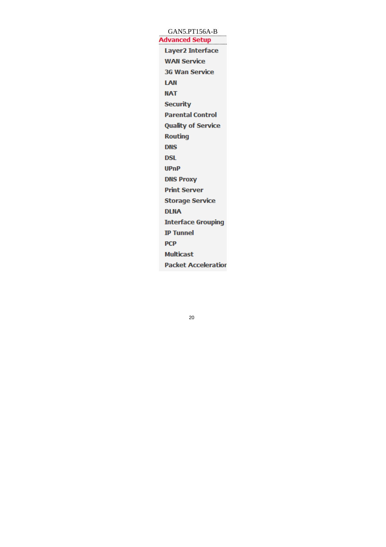
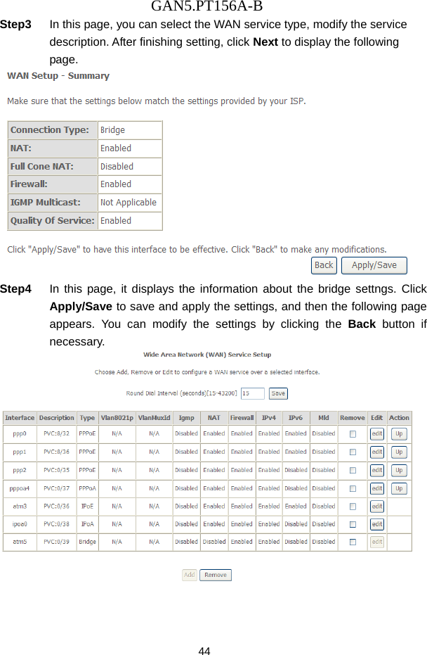
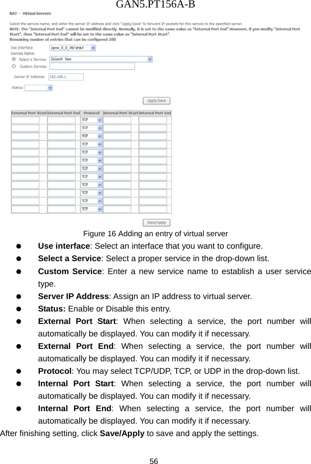
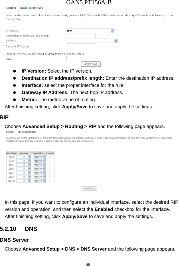
![GAN5.PT156A-B 80 PCP Server Name (IPv4/IPv6): The server side of the PCP protocol via which PCP clients request and manage explicit mappings. Lifetime (seconds): Requested Lifetime. Internal Port [0-65535]: Internal port for the mapping. The value 0 indicates "all ports". Suggested External Port [0-65535]: Suggested external port for the mapping. This is useful for refreshing a mapping, especially after the PCP server loses state. If the PCP client does not know the external port, or does not have a preference, it MUST use 0. Suggested External IP Address (IPv4/IPv6): Suggested external IPv4 or IPv6 address. This is useful for refreshing a mapping, especially after the PCP server loses state. If the PCP client does not know the external address, or does not have a preference, it MUST use the address-family-specific all-zeroes address. Third Party: It is an Internal Host when a PCP client wants to control a mapping other than itself.](https://usermanual.wiki/Gongjin-Electronics/R5500UN/User-Guide-2599537-Page-84.png)
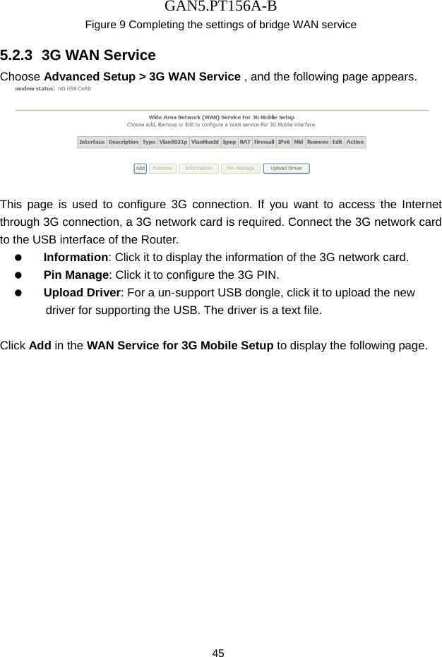
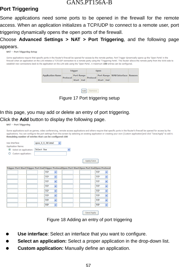
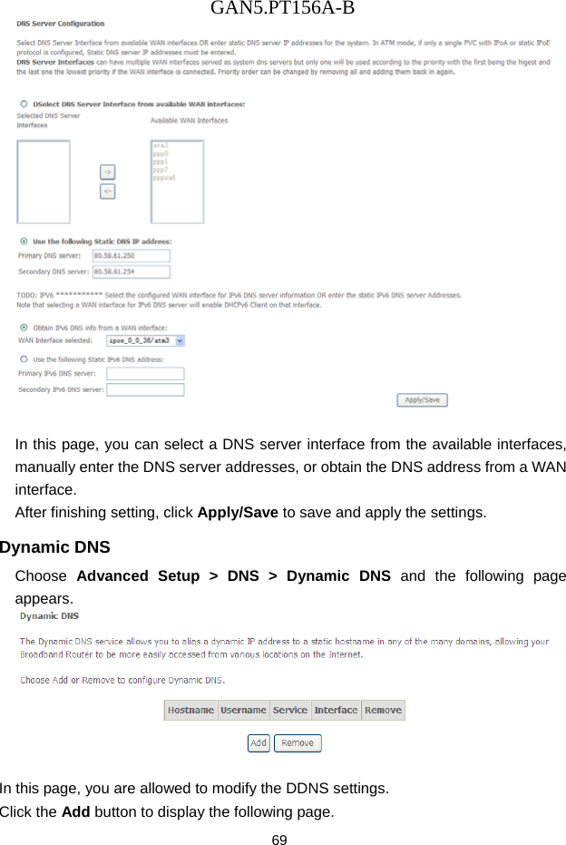
![GAN5.PT156A-B 81 Prefer Failure: This Option indicates that if the PCP server is unable to map either the Suggested External Port or Suggested External Address, the PCP server should not create a mapping. Peer Opcode Choose Advanced Setup > PCP > Peer Opcode and the following page appears. PCP Server Name (IPv4/IPv6): The server side of the PCP protocol via which PCP clients request and manage explicit mappings. Lifetime (seconds): Requested Lifetime. Internal Port [0-65535]: Internal port for the mapping. Suggested External Port [0-65535]: Suggested external port for the mapping. If the PCP client does not know the external port, or does not have a preference, it MUST use 0. Suggested External IP Address (IPv4/IPv6): Suggested External IP Address for the mapping. If the PCP client does not know the external address, or does not have a preference, it MUST use the address-family- specific all-zeroes address.](https://usermanual.wiki/Gongjin-Electronics/R5500UN/User-Guide-2599537-Page-85.png)
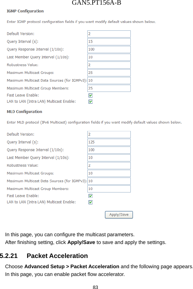
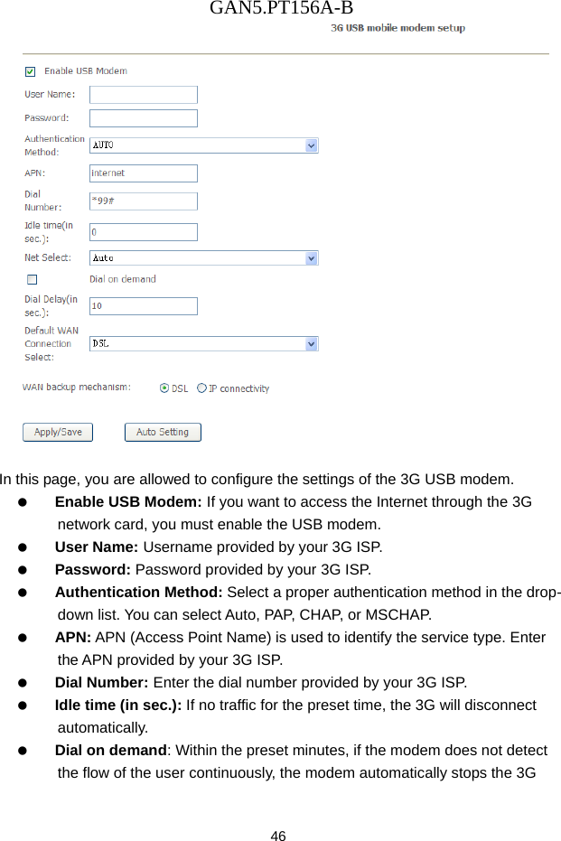
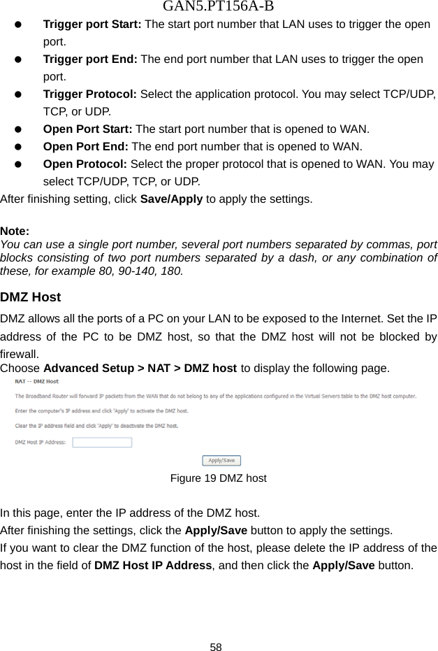
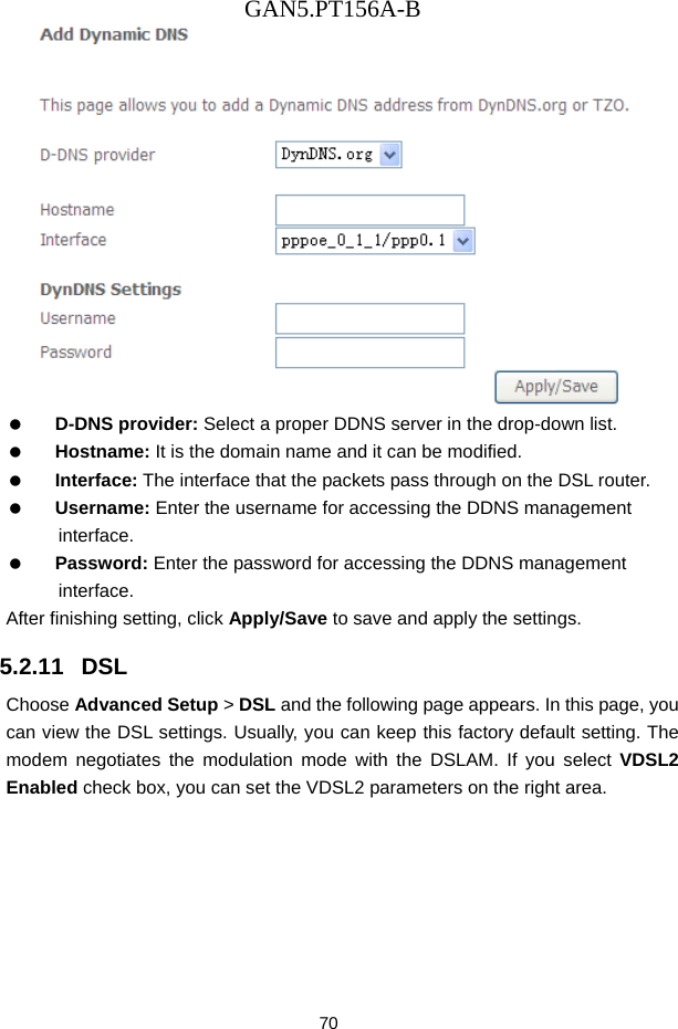
![GAN5.PT156A-B 82 Remote Peer Port [0-65535]: Remote peer's port for the mapping. Remote Peer IP Address (IPv4/IPv6): Remote peer's IP address from the perspective of the PCP client, so that the PCP client does not need to concern itself with NAT64 or NAT46. This field allows the PCP client and PCP server to disambiguate multiple connections from the same port on the Internal Host to different servers. An IPv6 address is represented directly, and an IPv4 address is represented using the IPv4-mapped address syntax. Third Party: It is an Internal Host when a PCP client wants to control a mapping other than itself. 5.2.20 Multicast Choose Advanced Setup > Multicast and the following page appears.](https://usermanual.wiki/Gongjin-Electronics/R5500UN/User-Guide-2599537-Page-86.png)