Good Way Technology TD1120 Z-Wave Window / Door Detector User Manual TD1120Z1 indd
Good Way Technology Co., Ltd. Z-Wave Window / Door Detector TD1120Z1 indd
Exhibit 08 Users Manual

Z-Wave® Window/
Door Detector
User's ManualUser's Manual

3
Table of Contents
Safety instructions .......................................................................4
Copyright .......................................................................................4
Trademarks ................................................................................... 4
Introduction ...................................................................................5
Features.........................................................................................5
Package contents .........................................................................5
Basic requirement ........................................................................5
Application diagram .....................................................................6
Product overview..........................................................................7
Battery installation .......................................................................8
Operation .......................................................................................9
- Inclusion ......................................................................................9
- Exclusion ................................................................................... 10
- Reset ......................................................................................... 10
Command classes ...................................................................... 11
- Description of command class .................................................. 12
Association ................................................................................. 17
Dip switch .................................................................................... 19
Installation ................................................................................... 20
- Internal connection .................................................................... 20
- Extension the detector (optional)............................................... 21
- Assemble the wire ..................................................................... 22
Mounting the detector ................................................................ 23
LED indicator .............................................................................. 25
Specifi cations ............................................................................. 26
Regulatory compliance .............................................................. 27
- FCC conditions .......................................................................... 27
- WEEE information ..................................................................... 27

4
Before attempting to connect, operate or adjust this product, please
save and read the User's Manual completely. The style of the
product shown in this User's Manual may be different from the actual
unit due to various models.
Safety instructions
Always read the safety instructions carefully:
■ Keep this User’s Manual for future reference
■ Keep this equipment away from humidity
■ If any of the following situation arises, get the equipment
checked by a service technician:
• The equipment has been exposed to moisture.
• The equipment has been dropped and damaged.
• The equipment has obvious sign of breakage.
• The equipment has not been working well or cannot get
it to work according to the User’s Manual.
Copyright
This document contains proprietary information protected
by copyright. All right are reserved. No part of this manual
may be reproduced by any mechanical, electronic or other
means, in any form, without prior written permission of the
manufacturer.
Trademarks
All trademarks and registered trademarks are the property
of their respective owners or companies.

5
Introduction
This unit is designed to detect the open or close status of
door or window. It is easy to install and fully compatible with
Z-Wave® technology. With the built-in Z-Wave®module, user
can monitor the door or window status anywhere, even they
are away from home. Besides, it can communicate with
other Z-Wave® devices, as long as the controller has been
certifi ed by Z-Wave®.
Features
■ Support device linking to trigger multiple devices to
provide maximum security
■ Fully compatible with Z-wave® enabled network, capable
of communicating with any Z-wave® certified device
■ Internal and external sensors included
Package contents
■ Z-Wave® Window/Door detector x1
■ Contact Magnet x1
■ 1.5V AAA battery x2
■ User’s Manual x1
■ External wired contactor with contact magnet (optional)
Basic requirement
■ An available Z-Wave® network or certifi ed Z-Wave® dongle
/ controller
6
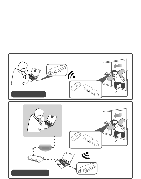
Application diagram
The illustrations below show the applications of the Z-Wave®
Door/Window Detector. With the built-in Z-Wave®, the
detector can be remoted through a Z-Wave® dongle or
controller at home or anywhere. Note that the application
may be different from the actual conditions.
Computer
Z-Wave®
Connection
Remote control
Z-Wave®
USB Dongle
Broadband
modem
Internet
Computer
Z-Wave®
USB Dongle
Z-Wave®
Connection
Local control
Web UI
* The web user interface (UI) may vary depending on the software
provided by Z-Wave dongle.
Web UI
7
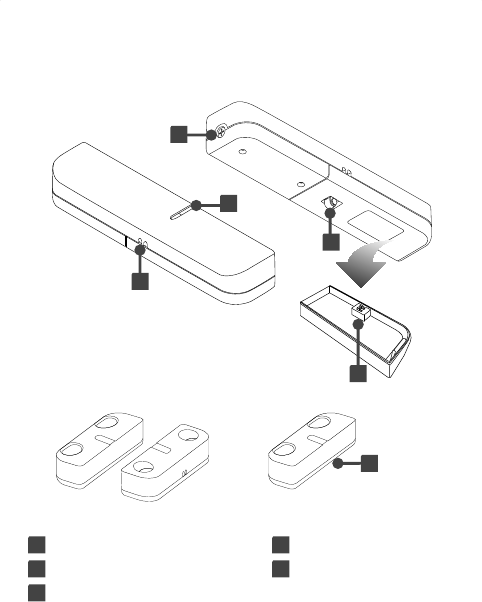
Product overview
Detector
4
Contact
magnet
External wired
contactor and contact
magnet (optional)
1
2
3
4
5
1 Screw for battery cover 2 LED indicator
3 Program Button 4 Wire through out
5 Dip switch
8
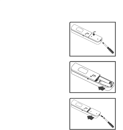
Battery installation
1. Unscrew the screw using
screwdriver, and then remove
the battery cover from rear
panel of the detector.
2. Place 2 AAA batteries
(1.5A) following the
orientation as shown on the
battery compartment. It is
recommended to use alkaline
batteries.
3. Place the battery cover, and
then tighten the supplied
screw.
Battery cover

9
Operation
Inclusion
Note: Make sure a Z-Wave® remote controller has been
installed and included to an available Z-Wave® network
before joining the Z-Wave® Window/Door Detector.
Not all Z-Wave® enabled remote controllers have the same
installation process. Actual instructions may vary, it depends
on the software that Z-Wave® controller provided.
1. Before starting the inclusion process, be
sure the DIP switch is setup to the default.
To switch the DIP, refer to DIP switch
chapter.
2. Press the <Program> button 3 times within 2 seconds on
the Z-Wave® Window/Door Detector to include a Z-Wave®
network. LED fl ashes green during the inclusion process.
3. Once the Z-Wave® Window/Door Detector has been
detected, the LED will stop fl ash, and the detected
information will be displayed on the controller's panel or
utility software.
Default
setting

10
Exclusion
To exclude the Z-Wave® network, operate the exclusion
procedure from the controller, and then press <Program>
button 3 times within 2 seconds on the Z-Wave® Window/
Door Detector.
Reset
To reset the Z-Wave® Window/Door Detector, press
<Program> button 3 times within 2 seconds and the third
for over 1 second.

11
Command classes
Command class is a programming protocol which allows
the Z-Wave® Window/Door Detector to communicate with
other compatible
Z-Wave®
devices. 2 association groups are
supported by the Z-Wave® Window/Door Detector.
The Z-Wave
®
Window/Door Detector supports 2 association
groups. Group1 supports the report of Alarm and warning
message when the battery is low. Only one device can be
associated in group1. Group2 supports to associate with
5 devices which means all the devices associated with the
Z-Wave
®
Widow/Door Detector will receive the relevant
reports once the Z-Wave
®
Window/Door is triggered and
confi gured.
To program the Z-Wave
®
Window/Door Detector, choose
one of the command classes below, and then adjust the
parameters. For more detailed confi gurations, refer to the
controller's instruction manual.
■ COMMAND_CLASS_BASIC
■ COMMAND_CLASS_SENSOR_BINARY
■ COMMAND_CLASS_WAKE_UP
■ COMMAND_CLASS_ASSOCIATION
■ COMMAND_CLASS_CONFIGURATION
■ COMMAND_CLASS_BATTERY
■ COMMAND_CLASS_MANUFACTURER_SPECIFIC
■ COMMAND_CLASS_VERSION

12
Z-Wave® Window/Door Detector Device Information
Basic Type: BASIC_TYPE_ROUTING_SLAVE
Generic Type: GENERIC_TYPE_SENSOR_BINARY
Specifi c Type: SPECIFIC_TYPE_ROUTING_SENSOR_
BINARY
Description of command class
Sensor binary command class
The user can also enquire the Sensor status of the unit
SENSOR_BINARY_GET, it will return SENSOR_BINARY
Command.
SENSOR_BINARY Command:
Magnets to be opened:
[Command Class Sensor Binary, Sensor Binary Report,
Sensor Binary Value = 0xFF]
Magnets to be closed:
[Command Class Sensor Binary, Sensor Binary Report,
Sensor Binary Value = 0x00]
Battery command class
The user can also enquire the battery status of the unit
BATTERY_GET command via Z-WAVE Controller, it will
return BATTERY_REPORT Command. If it will send Battery
Level = 255(0xFF) command to the Z-Wave® Controller to
inform that it is in low battery status.

13
Battery Report Command:
[Command Class Battery, Battery Report, Battery Level =
20%-100%]
Wake up command class
The Z-Wave
®
Window/Door Detector stays in sleep status
for the majority of time in order to conserve battery power.
However, it can be woken up at specifi ed intervals by
setting WAKE_UP_INTERVAL_SET command by Z-Wave
®
Controller.
After the Z-Wave
®
Window/Door Detector wakes up, it
will send Wakeup Notifi cation Command to the node ID
that requires to be report and stay awake for 5 seconds, if
no WAKE_UP_NO_MORE_INFORMATION command is
received. The Minimum wake up time is 60 seconds, the
maximum wake up time is 194 days.
Command Min MAX Default
WAKE UP 60 seconds 194 Days 1 day
Association command class
The Z-Wave® Window/Door Detector can be set up to 5
devices in group 2. For hardware connection details, refer to
Association chapter.

14
Alarm command class
The ALARM_REPORT will be sent to the controller when
the batteries have been inserted properly into the Z-Wave
®
Window/Door Detector.
1. Power applied
Once the batteries has been inserted, Alarm Report
Command will be sent to Nodes in group1 to confi rm the
power status for the Z-Wave
®
Window/Door Detector.
[Command Class Alarm , Alarm Report, Alarm Level =
0x02,Alarm Type = 0x01]
2. Low battery report
When the Z-Wave
®
Window/Door Detector automatically
wakes up, it will check the battery usage. When low
battery is detected , Alarm Report Command will be sent
to Nodes in group1.
[Command Class Alarm , Alarm Report, Alarm Level =
0x02,Alarm Type = 0xFF]
3. Tamper event report
When Z-Wave
®
Window/Door Detector is pressed and
hold the tamper switch more than 10 seconds then
release, it will sent , Alarm Report Command will be sent
to Nodes in group1
[Command Class Alarm , Alarm Report, Alarm Level =
0x02,Alarm Type = 0x11]

15
Basic command class
When door/window is opened, the will send Basic SET
command contains a value that is adjustable, to the node of
group2. For instance, a lamp module will be turned off after
receiving the BASIC_SET command.
Magnets to be opened:
[Command Class Basic , Basic Set, Basic Value = 0xFF]
Magnets to be closed:
[Command Class Basic , Basic Set, Basic Value = 0x00]
Confi guration command class
This class is used for setting certain vendor specifi c
confi guration variables to the node of group2.
See the following table for confi guration variables:
Id Name Size Range Default
value
Description
0x01 Basic Set level 1 bytes 1– 99 99 Ex: 1~99
1. ON (Binary
switch device)
2. Dim Level
(Multilevel
switch device)
0x02 Delay time
before the OFF
command be
transmitted
1 bytes 0 – 127 0s 0– 127: seconds

16
Version command class
Implemented according to command class specifi cation.
Manufacturer specifi c command class
Implemented according to command class specifi cation.
17
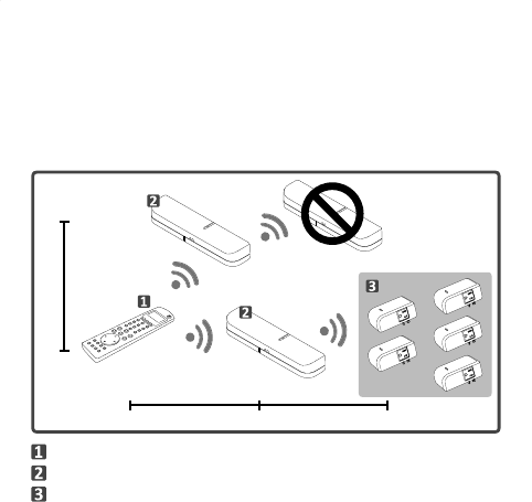
Association
Defi ne the relationship between devices after joining to
Z-Wave® network. Device can be assigned as master/slave,
and the slave can be controlled by the master.
Within 30m approx.
Within 30m approx. Within 30m approx.
Z-Wave® remote controller
Z-Wave® Window/Door detector
Z-Wave® compatible appliances
18
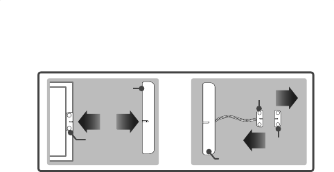
1. Before associating the Z-Wave® Window/Door Detector,
please disconnect Detector and Contact Magnet.
Contact
magnet
Detector
or
Wired
contact
Contact
magnet
Detector
2. Associate the Z-Wave® Window/Door Detector with a
controller.
3. Associate the appliances under Z-Wave® Window/Door
Detector using
Z-Wave®
controller or utility software. The
supported appliances is up to 5.
4. Once the setup is completed, the Window/Door Detector
can be used as a bridge to transmit the commands from
controller to the associated Z-Wave® appliances.
Note: The Z-Wave® Window/Door Detector does not support
to associate other Z-Wave® Window/Door Detectors.
19
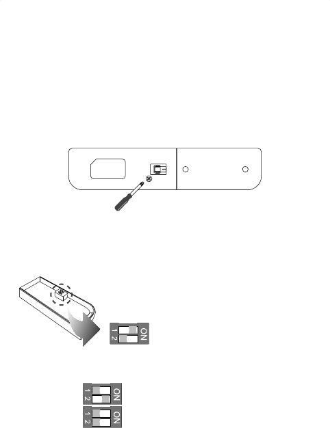
Dip switch
The Z-Wave® Window/Door detector can be setup to internal
or external connections. Follow the steps below to adjust
the dip before installing the detector to a door or window.
1. Loosen the screws from the rear panel, and then remove
the cover.
2. Adjust the dip switches using a fi nger or fi nger nail
according to the desired connection of the Window/Door
detector.
Default or Internal connection
Note: Adjust the dip switches to
default before including or excluding
the detector to a Z-Wave
®
network.
External connection
External and Internal mixed connection
20
Installation
Before installing the Z-Wave® Window/Door Detector, make
sure the Detector has been included to a Z-Wave
®
network.
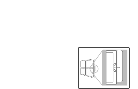
Internal connection
1. Adjust the dip switch to the
default. Refer to Dip switch
chapter for more details.
2. Mount the Z-Wave® Window/
Door detector to a window or
door following the previous
section.
3. Install the contact magnet to the moving part of the
window or door opposite to the detector. Make sure the
window or door is closed when installing.
Note: For better performance, make sure the gap between
detector and contact magnet is less then 10mm.
21
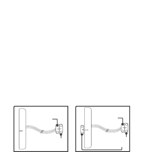
Extension the detector (optional)
Sometimes the type of window or door may differ from the
previous section, users may need to extend the Window/
Door Detector using wires.
1. Adjust the dip switch according to the desired connection
before installing to a door or window. Refer to Dip switch
chapter for more details.
2. Extend the wired contact using two core (24AWG) wires
and the maximum length is 4m. Refer to the Assemble
the wire chapter for more information.
Wired contact
Contact
magnet
Wired contact
Contact
magnet
External and internal
connection mixed mode
External connection
22
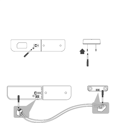
Assemble the wire
1. Loosen the screws from the rear panel, and then remove
the cover.
Detector Wired contactor
2. Insert the cable (24AWG) into the block as shown below,
and then tighten the screws on the top.
23
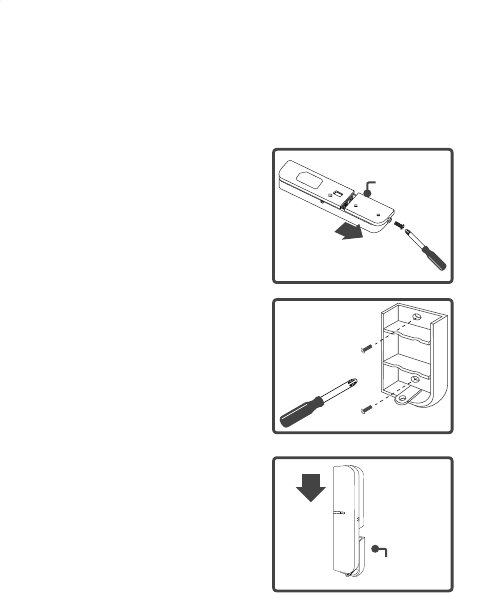
Mounting the detector
The Z-Wave® Window/Door Detector can be mounted on
any location that can be open or closed, such as closets,
doors, windows or safes.
1. Unscrew the battery cover
from the detector and slide the
cover off.
2. Use the screws that are
provided to screw the cover
onto your desired location.
3. Slide the detector back on the
cover.
Battery cover
Battery cover
Battery cover
24
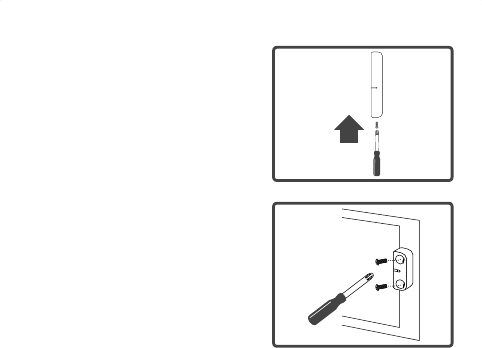
4. Tighten the screw.
5. Install the contact magnet to
the moving part of the window
or door which is opposite to
the detector using screws.

25
LED indicator
Refer to the table below to see the status of LED.
LED Description
Green Flashes when including to a Z-Wave® network
Flashes when excluding from a Z-Wave® network
Flashes when data transmitting or receiving
Lights green when waking up from sleeping mode
* Sleeping mode: To save the power, the detector will
enter sleeping mode automatically after 5 seconds when
the installation is completed.
Red Low power, and fl ashes every 5 seconds

26
Specifi cations
Item Description
Protocol Z-Wave®
Detective type Magnetism reed switch
Power AAA battery 1.5V*2
LED Indicator Bicolor LED (Green / Red)
Switch Inclusion / Exclusion button
Frequency 908.42MHz
Operating Rang Up to 100 feet (30m) approx.
Data Rate 9.6kbps / 40kbps
Application Indoor use
Working
Environment
Operating Temperature: 0~40ºC
Storage Temperature: -10~55ºC
Dimensions
(LxWxH)
Detector: 130x28x21.8mm
Contact Magnet/Wired Magnet:
45x14x12.7mm
Housing Plastic
Flame Class UL 94 V-0
Surface
Processing
Painting
Compliance FCC

Regulatory compliance
FCC conditions
This equipment has been tested and found to comply with the limits for a Class B digital
device, pursuant to part 15 of the FCC rules. These limits are designed to provide
reasonable protection against harmful interference in a residential installation. This
equipment generates, uses and can radiate radio frequency energy and, if not installed
and used in accordance with the instructions, may cause harmful interference to radio
communications. However, there is no guarantee that interference will not occur in a
particular installation. If this equipment does cause harmful interference to radio or
television reception, which can be determined by turning the equipment off and on, the
user is encouraged to try to correct the interference by one or more of the following
measures:
-Reorient or relocate the receiving antenna.
-Increase the separation between the equipment and receiver.
-Connect the equipment into an outlet on a circuit different from that to which the
receiver is connected.
-Consult the dealer or an experienced radio/TV technician for help.
You are cautioned that changes or modifications not expressly approved by the party
responsible for compliance could void your authority to operate the equipment.
This device complies with Part 15 of the FCC Rules. Operation is subject to the
following two conditions:
(1) this device may not cause harmful interference and
(2) this device must accept any interference received, including interference that may
cause undesired operation
WEEE information
For EU (European Union) member users: According to
the WEEE (Waste electrical and electronic equipment)
Directive, do not dispose of this product as household
waste or commercial waste. Waste electrical and electronic
equipment should be appropriately collected and recycled
as required by practices established for your country. For
information on recycling of this product, please contact your
local authorities, your household waste disposal service or
the shop where you purchased the product.