Goodman Mfg Co Lp Furnace Gmv95 Gcv9 Users Manual SS
Multi-Position, Two-StageVariable-Speed Gas Furnace to the manual a07cff7f-5b63-4291-b8e3-a6b34f2ce38a
2015-02-02
: Goodman-Mfg Goodman-Mfg-Goodman-Mfg-Co-Lp-Furnace-Gmv95-Gcv9-Users-Manual-429688 goodman-mfg-goodman-mfg-co-lp-furnace-gmv95-gcv9-users-manual-429688 goodman-mfg pdf
Open the PDF directly: View PDF ![]() .
.
Page Count: 16
HEATING INPUT: 46,000–115,000 BTU/H
Standard Features
• Patented Tu Tube™ dual-diameter tubular heat exchanger
with Lifetime Limited Warranty* for as long as the original
registered homeowner owns their home plus 10-Year Limited
Unit Replacement Warranty*
• Two-stage gas valve operates with two-stage or single-
stage thermostats
• E cient and quiet variable-speed circulator motor gently ramps
up or down according to heating or cooling demand
• 110V Silicon Nitride igniter designed for long igniter life
• Furnace control board with self-diagnostics, color-coded low-
voltage terminals, and provisions for electronic air cleaner and
120-volt or 24-volt humidi ers
• Low constant fan allows homeowner to activate very low
speed to e ciently circulate air throughout the home. This
setting costs as little as a 100-watt light bulb to operate.
• Dual-certi ed for sealed combustion direct vent (2-pipe)
or non-direct vent (1-pipe) applications
• Quiet two-speed induced draft blower
• All models comply with California NOx emissions standards
Cabinet Features
• Fully insulated, heavy-gauge steel cabinet with durable
baked-enamel nish
• Foil-faced insulation lines the heat exchanger
• Easy-to-install top venting is standard; alternate ue/vent
located on the right (GMV95)
• Designed for multi-position installation – GMV95: up ow,
horizontal left or right; GCV9: down ow, horizontal left or right
• Airtight solid bottom for side return applications and easy-cut
tabs for e ortless removal in bottom air inlet applications
• Convenient left or right connection for gas and electric service
• Coil and furnace t ush for most installations
Contents
Nomenclature ................................................................................................2
Product Speci cations ................................................................................3
Dimensions .....................................................................................................4
Blower Performance Speci cations ........................................................7
Wiring Diagrams .........................................................................................13
Accessories ................................................................................................... 15
The Goodman® brand GMV95/ GCV9 Two-Stage, Variable-
Speed Gas Furnaces feature a patented aluminized-steel
tubular heat exchanger and durable Silicon Nitride Hot
Surface Ignition system.
GMV95: UP TO 95% AFUE
GCV9: UP TO 93% AFUE
MULTI-POSITION,
TWO-STAGE/VARIABLE-SPEED
GAS FURNACE
*To receive the Lifetime Heat Exchanger Limited Warranty, 10-Year Unit Replacement Limited Warranty and
10-Year Parts Limited Warranty, online registration must be completed within 60 days of installation. Online
registration is not required in California or Québec. Full warranty details available at www.goodmanmfg.com.
Applies to 95% furnaces only.
PRODUCT SPECIFICATIONS
SS-GMV95 www.goodmanmfg.com 6/09
Supersedes 3/09
GMV95/GCV9
2 www.goodmanmfg.com SS-GMV95
PRODUCT SPECIFICATIONS
NOMENCLATURE
Brand Revisions
GGoodman
®
Brand A Initial Release
or Distinctions™ B 1st Revision
C 2nd Revision
Airflow Direction
C Downflow/Horizontal
D Dedicated Downflo
w
NOx
H High Airflow N Natural Gas
K Dedicated Upflow X Low NOx
M Upflow/Horizontal
Cabinet Width
Description A 14”
V Two-Stage/Variable-speed B 17½”
H Two-Stage/Multi-speed C 21”
S Single-Stage/Multi-speed D 24½”
E Two-Stage/X-13 Motor
AFUE Maximum CFM @ 0.5” ESP
95 95% 3 1,200
9 90%+ 4 1,600
8 80% 5 2,000
MBTU/h
045: 45,000 115: 115,000
070: 70,000 140: 140,000
090: 90,000
V
3
4
6,7,84,5
95 70M
21
G
9
B
11
X
10 12
A
Important EnergyStar Notice: EnergyStar ratings are dependent
upon conditions beyond equipment installation. Proper sizing
and installation of equipment is critical to achieve optimal
performance. Split system air conditioners and heat pumps
must be matched with appropriate coil components to meet
EnergyStar criteria. Ask your contractor for details or visit
www.energystar.gov.
SS-GMV95 www.goodmanmfg.com 3
PRODUCT SPECIFICATIONS
SPECIFICATIONS
GMV95
0453BXB GMV95
0704CXB GMV95
0905DXB GMV95-
1155DXB GCV9
0704CXB GCV9
0905DXB GCV9
1155DXA
Heating Capacity
High Fire Input¹ 46,000 69,000 92,000 115,000 69,000 92,000 115,000
High Fire Output¹ 45,000 67,000 90,000 109,000 65,000 87,000 109,000
Low Fire Input¹ 32,000 48,000 64,000 80,000 48,000 64,000 80,000
Low Fire Output¹ 30,800 46,400 61,700 77,400 45,000 60,100 77,400
AFUE² 95 95 95 95 93 93 93
Tons AC @ 0.5” ESP 1.5 - 3.0 1.5 - 4.0 2.0 - 5.0 2.0 - 5.0 1.5 - 4.0 2.0 - 5.0 2.0 - 5.0
Temperature Rise Range (°F) 30 - 60 30 - 60 30 - 60 30 - 60 30 - 60 30 - 60 40-70
Circulator Blower
Size (D x W) 10” X 7” 10” X 10” 11” X 10” 11” X 10” 10” x 10” 11” X 10” 11” X 10”
Horespower @ 1750 RPM ½ ¾ 1 1 ¾ 1 1
Speed Variable Variable
Vent Diameter³ 2” 2” 3” 3” 2” 3” 3”
No. of Burners 2 3 4 5 3 4 5
Filter Size (in²)
Disposable 288 384 480 486 384 480 486
Permanent 576 768 960 972 768 960 972
Electrical Data
Min. Circuit Ampacity (amps)410.4 12.8 14.6 14.6 12.8 14.6 14.6
Max. Overcurrent Protection515 amps 15 amps 15 amps 15 amps 15 amps 15 amps 15 amps
Ship Weight (lbs) 133 135 172 175 135 172 175
1– Natural Gas BTU/h
2– DOE AFUE based upon Isolated Combustion System (ICS)
3– Installer must supply one or two PVC pipes: one for combustion air (optional) and one for the ue outlet (required). Vent pipe must
be either 2” or 3” in diameter, depending upon furnace input, number of elbows, length of run and installation (1 or 2 pipes). The
optional Combustion Air Pipe is dependent on installation/code requirements and must be 2” or 3” diameter PVC.
4– Minimum Circuit Ampacity = (1.25 x Circulator Blower Amps) + ID Blower amps. Wire size should be determined in accordance with
National Electrical Codes. Extensive wire runs will require larger wire sizes.
5– Maximum Overcurrent Protection Device refers to maximum recommended fuse or circuit breaker size. May use fuses or HACR-type
circuit breakers of the same size as noted.
Notes:
• All furnaces are manufactured for use on 115 VAC, 60 Hz, single-phase electrical supply.
• Gas Service Connection ½” FPT
• Important: Size fuses and wires properly and make electrical connections in accordance with the National Electrical Code
and/or all existing local codes.
4 www.goodmanmfg.com SS-GMV95
PRODUCT SPECIFICATIONS
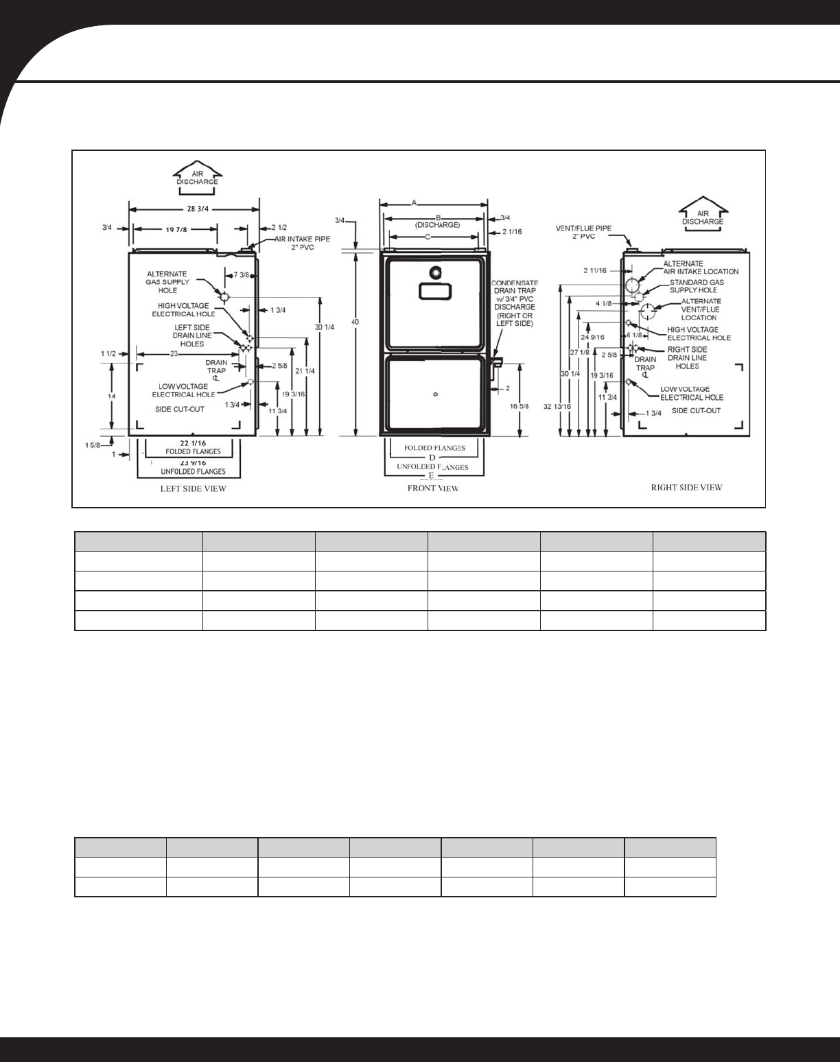
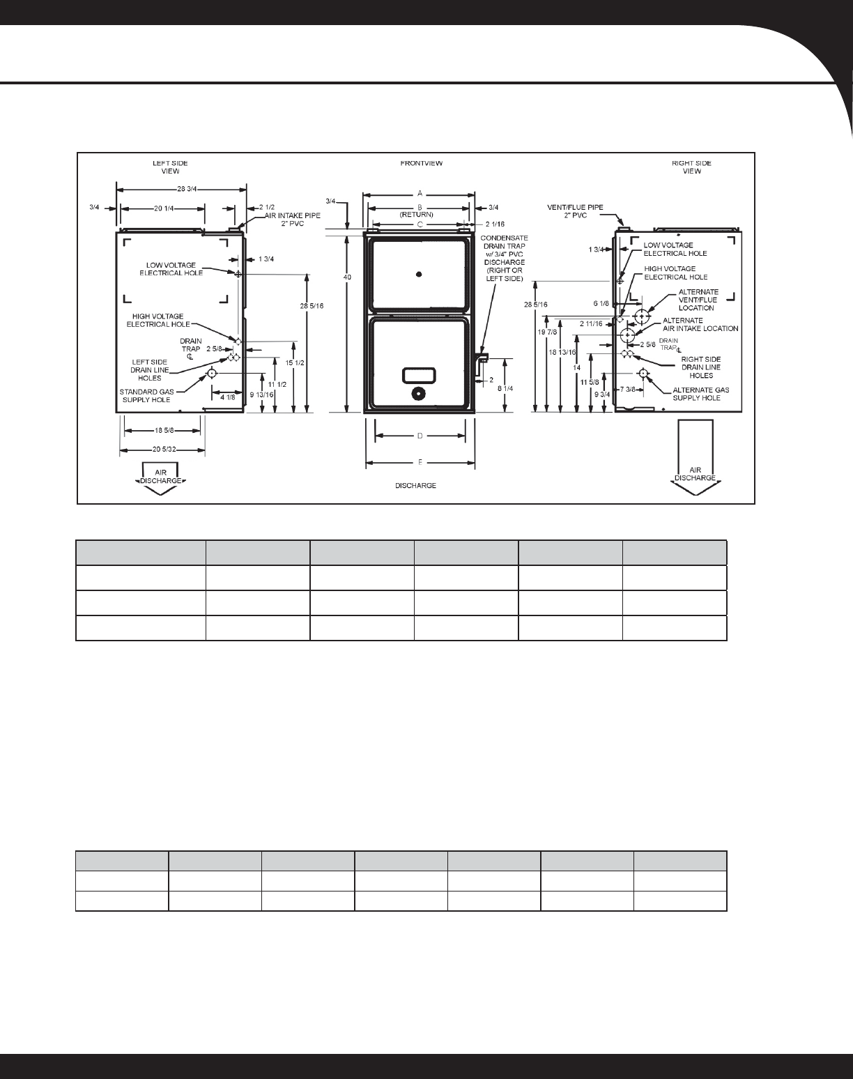
GMV95 DIMENSIONS
MINIMUM CLEARANCES TO COMBUSTIBLE MATERIALS
Position Sides Rear Front Bottom Flue Top
Upfl ow 0” 0” 3” C 0” 1”
Horizontal 6” 0” 3” C 0” 6”
C = If placed on combustible fl oor, the fl oor MUST be wood ONLY.
Notes:
• For servicing or cleaning, a 24” front clearance is required.
• Unit connections (electrical, fl ue and drain) may necessitate greater clearances than the minimum clearances listed above.
• In all cases, accessibility clearance must take precedence over clearances from the enclosure where accessibility clear-
ances are greater.
Model A B C D E
GMV950453BXB 17½” 16” 13⅛”12⅛”13⅝”
GMV950704CXB 21” 19½” 16⅛” 16 17½”
GMV950905DXB 24½” 23” 20⅝”19⅜”20⅞”
GMV951155DXB 24½” 23” 20⅝”19⅜”20⅞”
Notes:
• Installer must supply one or two PVC pipes: one for combustion air (optional) and one for the fl ue outlet (required). Vent pipe must be
either 2” or 3” in diameter, depending upon furnace input, number of elbows, length of run and installation
(1 or 2 pipes). The optional Combustion Air Pipe is dependent on installation/code requirements and must be 2” or 3” diameter PVC.
• Line voltage wiring can enter through the right or left side of the furnace. Low-voltage wiring can enter through the right or left side of
furnace.
• Conversion kits for high-altitude natural gas operation are available. Contact your Goodman distributor or dealer for details.
• Installer must supply following gas line fi ttings, according to which entrance is used:
Left—Two 90º elbows, one close nipple, straight pipe
Right—Straight pipe to reach gas valve
• For bottom return: Failure to unfold fl anges may reduce airfl ow by up to 18%. This could result in performance and noise issues.
SS-GMV95 www.goodmanmfg.com 5
PRODUCT SPECIFICATIONS
GCV9 DIMENSIONS
FOLDED FLANGES
UNFOLDED FLANGES
FOLDED FLANGES
UNFOLDED FLANGES
Model A B C D E
GCV90704CXB 21” 19½” 16⅛” 18” 19½”
GCV90905DXB 24½” 23” 20⅝” 21½” 23”
GCV91155DXB 24½” 23” 20⅝” 21½” 23”
Notes:
• Installer must supply one or two PVC pipes: one for combustion air (optional) and one for the fl ue outlet (required). Vent pipe must be
either 2” or 3” in diameter, depending upon furnace input, number of elbows, length of run, and installation (1 or 2 pipes). The optional
Combustion Air Pipe is dependent on installation/code requirements and must be 2” or 3” diameter PVC.
• Line voltage wiring can enter through the right or left side of the furnace. Low-voltage wiring can enter through the right or left side of
furnace.
• Conversion kits for high-altitude natural gas operation are available. Contact your Goodman distributor or dealer for details.
• Installer must supply following gas line fi ttings, according to which entrance is used:
Left—Two 90º Elbows, one close nipple, straight pipe
Right—Straight pipe to reach gas valve
• For bottom return: Failure to unfold fl anges may reduce airfl ow by up to 18%. This could result in performance and noise issues.
MINIMUM CLEARANCES TO COMBUSTIBLE MATERIALS
Position Sides Rear Front Bottom Flue Top
Downfl ow 0” 0” 3” NC 0” 1”
Horizontal 6” 0” 3” C 0” 6”
C = If placed on combustible fl oor, the fl oor MUST be wood ONLY.
NC = For installation on non-combustible fl oors only. A combustible fl oor sub-base must be used for installations on combustible fl ooring.
Notes:
• For servicing or cleaning, a 24” front clearance is required.
• Unit connections (electrical, fl ue and drain) may necessitate greater clearances than the minimum clearances listed above.
• In all cases, accessibility clearance must take precedence over clearances from the enclosure where accessibility clearances
are greater.
6 www.goodmanmfg.com SS-GMV95
PRODUCT SPECIFICATIONS
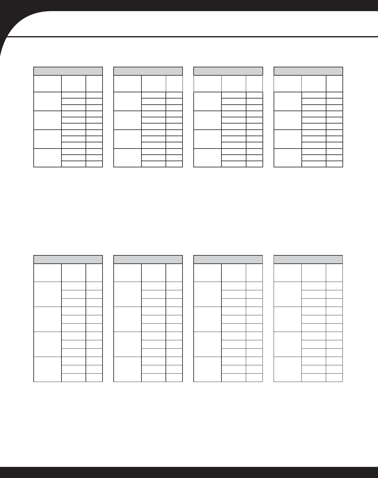
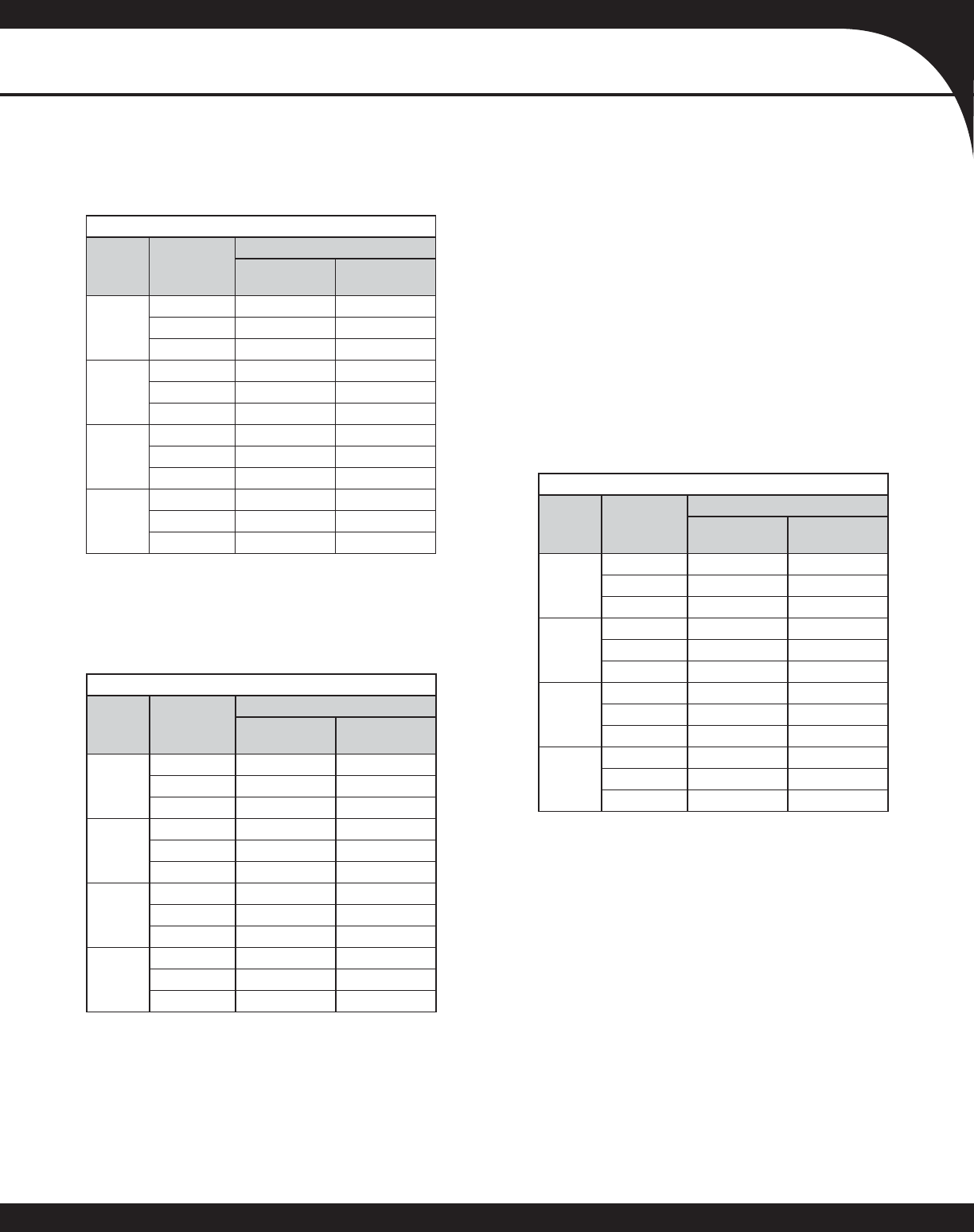
GMV95 HIGH- OR SINGLE-STAGE COOLING SPEEDS
GMV95 LOW-STAGE COOLING SPEEDS
GMV950453BXB GMV950704CXB GMV950905DXB GMV951155DXB
Cooling
Speed Tap Adjust
Tap CFM¹ Cooling
Speed Tap Adjust
Tap CFM¹ Cooling
Speed Tap Adjust
Tap CFM¹ Cooling
Speed Tap Adjust
Tap CFM¹
A
Minus (-) 540
A
Minus (-) 540
A
Minus (-) 720
A
Minus (-) 720
Normal 600 Normal 600 Normal 800 Normal 800
Plus (+) 660 Plus (+) 660 Plus (+) 880 Plus (+) 880
B
Minus (-) 720
B
Minus (-) 720
B
Minus (-) 990
B
Minus (-) 990
Normal 800 Normal 800 Normal 1,100 Normal 1,100
Plus (+) 880 Plus (+) 880 Plus (+) 1,210 Plus (+) 1,210
C
Minus (-) 900
C
Minus (-) 990
C
Minus (-) 1,260
C
Minus (-) 1,260
Normal 1,000 Normal 1,100 Normal 1,400 Normal 1,400
Plus (+) 1,100 Plus (+) 1,210 Plus (+) 1,540 Plus (+) 1,540
D
Minus (-) 1,080
D
Minus (-) 1,286
D
Minus (-) 1,620
D
Minus (-) 1,620
Normal 1,200 Normal 1,429 Normal 1,800 Normal 1,800
Plus (+) 1,320 Plus (+) 1,572 Plus (+) 1,980 Plus (+) 1,980
¹ @ .1” to .8” W.C. ESP
Notes:
• All furnaces ship as high speed for cooling. Installer must adjust blower speed as needed.
• For most jobs, about 400 CFM per ton when cooling is desirable.
• Do not operate above .5” w.c. ESP in heating mode. Operating CFM between .5” and .8” w.c. is tabulated for cooling purposes only.
• Constant Fan mode is 50% of above values
GMV950453BXB GMV950704CXB GMV950905DXB GMV951155DXB
Cooling
Speed Tap Adjust
Tap CFM¹ Cooling
Speed Tap Adjust
Tap CFM¹ Cooling
Speed Tap Adjust
Tap CFM¹ Cooling
Speed
Tap
Adjust
Tap CFM¹
A
Minus (-) 380*
A
Minus (-) 378*
A
Minus (-) 513*
A
Minus (-) 514*
Normal 390 Normal 390 Normal 520 Normal 520
Plus (+) 429 Plus (+) 429 Plus (+) 572 Plus (+) 572
B
Minus (-) 468
B
Minus (-) 468
B
Minus (-) 644
B
Minus (-) 644
Normal 520 Normal 520 Normal 715 Normal 715
Plus (+) 572 Plus (+) 572 Plus (+) 787 Plus (+) 787
C
Minus (-) 585
C
Minus (-) 644
C
Minus (-) 819
C
Minus (-) 819
Normal 650 Normal 715 Normal 910 Normal 910
Plus (+) 715 Plus (+) 787 Plus (+) 1,001 Plus (+) 1,001
D
Minus (-) 702
D
Minus (-) 836
D
Minus (-) 1,053
D
Minus (-) 1,053
Normal 780 Normal 929 Normal 1,170 Normal 1,170
Plus (+) 858 Plus (+) 1,022 Plus (+) 1,287 Plus (+) 1,287
¹ @ .1” to .8” W.C. ESP
Notes:
• All furnaces ship as high speed for cooling. Installer must adjust blower speed as needed.
• For most jobs, about 400 CFM per ton when cooling is desirable.
• Do not operate above .5” w.c. ESP in heating mode. Operating CFM between .5” and .8” w.c. is tabulated for cooling purposes only.
SS-GMV95 www.goodmanmfg.com 7
PRODUCT SPECIFICATIONS
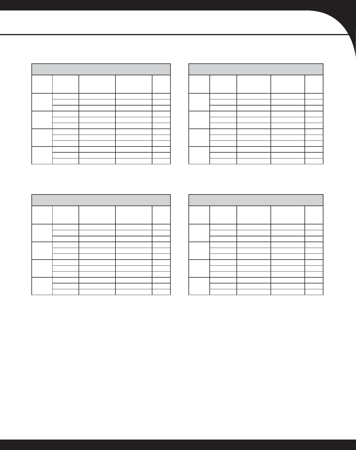
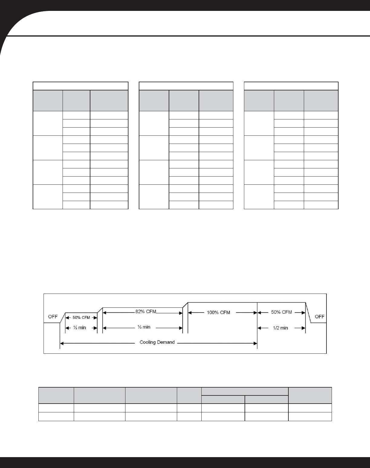
GMV950453BXB
(Rise Range: 30° - 60°F) GMV950704CXB
(Rise Range: 30° - 60°F)
Heating
Speed
Tap
Adjust
Tap
Low Stage
CFM @ .1” to
.5” W.C. ESP
High Stage
CFM @ .1” to
.5” W.C. ESP
Rise
(°F)
Heating
Speed
Tap
Adjust
Tap
Low Stage
CFM @ .1” to
.5” W.C. ESP
High Stage
CFM @ .1” to
.5” W.C. ESP
Rise
(°F)
A
Minus (-) 495 713 57
A
Minus (-) 756 1,089 56
Normal 550 792 51 Normal 840 1,210 50
Plus (+) 605 871 46 Plus (+) 924 1,331 46
B
Minus (-) 540 778 52
B
Minus (-) 828 1,192 51
Normal 600 864 47 Normal 920 1,325 46
Plus (+) 660 950 43 Plus (+) 1,012 1,457 42
C
Minus (-) 585 842 48
C
Minus (-) 900 1,296 47
Normal 650 936 43 Normal 1,000 1,440 42
Plus (+) 715 1,030 39 Plus (+) 1,100 1,584 38
D
Minus (-) 630 907 45
D
Minus (-) 972 1,400 43
Normal 700 1,008 40 Normal 1,080 1,555 39
Plus (+) 770 1,109 36 Plus (+) 1,188 1,711 35
GMV950905DXB
(Rise Range: 30° - 60°F) GMV951155DXB
(Rise Range: 30° - 60°F)
Heating
Speed
Tap
Adjust
Tap
Low Stage
CFM @ .1” to
.5” W.C. ESP
High Stage
CFM @ .1” to
.5” W.C. ESP
Rise
(°F)
Heating
Speed
Tap
Adjust
Tap
Low Stage
CFM @ .1” to
.5” W.C. ESP
High Stage
CFM @ .1” to
.5” W.C. ESP
Rise
(°F)
A
Minus (-) 1,013 1,458 56
A
Minus (-) 1,107 1,594 63
Normal 1,125 1,620 50 Normal 1,230 1,771 57
Plus (+) 1,238 1,782 45 Plus (+) 1,353 1,948 52
B
Minus (-) 1,076 1,549 52
B
Minus (-) 1,139 1,639 62
Normal 1,195 1,721 47 Normal 1,265 1,822 56
Plus (+) 1,315 1,893 43 Plus (+) 1,392 2,004 50
C
Minus (-) 1,139 1,639 49
C
Minus (-) 1,170 1,685 60
Normal 1,265 1,822 44 Normal 1,300 1,872 54
Plus (+) 1,392 2,004 40 Plus (+) 1,430 2,059 49
D
Minus (-) 1,202 1,730 47
D
Minus (-) 1,202 1,730 58
Normal 1,335 1,922 42 Normal 1,335 1,922 53
Plus (+) 1,469 2,115 38 Plus (+) 1,469 2,115 48
GMV95 HEATING SPEEDS
8 www.goodmanmfg.com SS-GMV95
PRODUCT SPECIFICATIONS
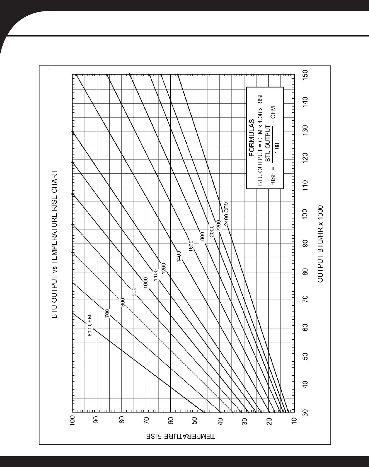
GMV95 BLOWER PERFORMANCE
SS-GMV95 www.goodmanmfg.com 9
PRODUCT SPECIFICATIONS
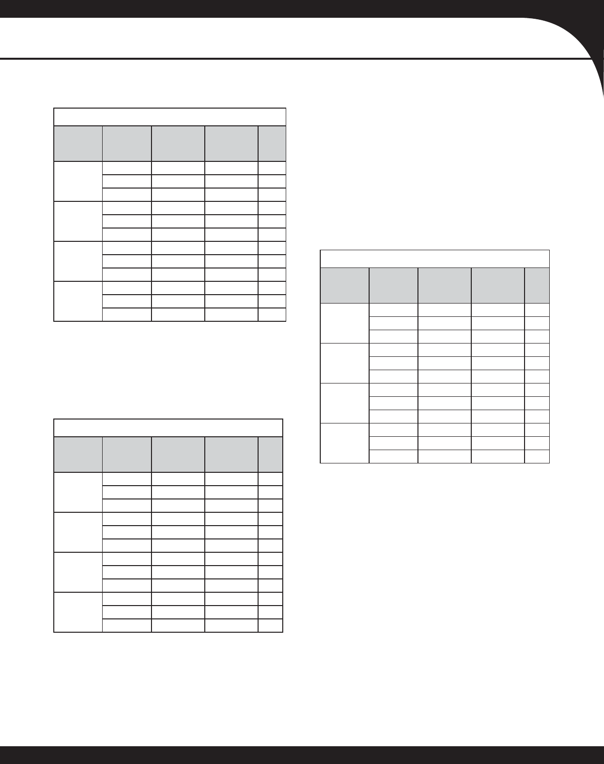
GCV9 COOLING SPEEDS
GCV90704CXA
Cooling
Speed
Tap
Adjust
Tap
CFM at .1” to .8” w.c. ESP
Low Stage High/Single-
Stage
A
Minus (-) 378* 540
Normal 390 600
Plus(+) 429 660
B
Minus (-) 468 720
Normal 520 800
Plus(+) 572 880
C
Minus (-) 644 990
Normal 715 1,100
Plus(+) 787 1,210
D
Minus (-) 836 1,286
Normal 929 1,429
Plus(+) 1,022 1,572
GCV90905DXA
Cooling
Speed
Tap
Adjust
Tap
CFM at .1” to .8” w.c. ESP
Low Stage High/Single-
Stage
A
Minus (-) 513* 720
Normal 520 800
Plus(+) 572 880
B
Minus (-) 644 990
Normal 715 1,100
Plus(+) 787 1,210
C
Minus (-) 819 1,260
Normal 910 1,400
Plus(+) 1,001 1,540
D
Minus (-) 1,053 1,620
Normal 1,170 1,800
Plus(+) 1,287 1,980
GCV91155DXA
Cooling
Speed
Tap
Adjust
Tap
CFM at .1” to .8” w.c. ESP
Low Stage High/Single-
Stage
A
Minus (-) 500* 705
Normal 508 783
Plus(+) 559 861
B
Minus (-) 621 982
Normal 690 1,091
Plus(+) 759 1,200
C
Minus (-) 815 1,265
Normal 906 1,406
Plus(+) 997 1,547
D
Minus (-) 1,049 1,628
Normal 1,165 1,809
Plus(+) 1,282 1,990
HIGH- /SINGLE-STAGE & LOW-STAGE COOLING SPEEDS
Notes:
• These charts are for furnaces installed at 0 - 2000 feet. At higher altitudes, a properly derated unit will have the same temperature rise at a
particular CFM, while the ESP at that CFM will be lower.
• The installation must be adjusted to obtain a temperature rise within the range listed on the furnace nameplate.
• Do not operate above .5” w.c. ESP in heating mode.
• Propane gas installations will have a High Stage rise approximately 4° lower than shown in above table.
* Motor CFM maximum
* Motor CFM maximum
* Motor CFM maximum
10 www.goodmanmfg.com SS-GMV95
PRODUCT SPECIFICATIONS
COOLING-BASED CONTINUOUS FAN SPEEDS
GCV90704CXA GCV90905DXA GCV91155DXA
Cooling
Speed Tap Adjust
Tap
Continuous
Fan Speed
CFM
Cooling
Speed Tap Adjust Tap Continuous
Fan Speed
CFM
Cooling
Speed Tap Adjust Tap Continuous
Fan Speed
CFM
A
Minus (-) 380*
A
Minus (-) 513*
A
Minus (-) 500*
Normal 380* Normal 513* Normal 500*
Plus(+) 380* Plus(+) 513* Plus(+) 500*
B
Minus (-) 403
B
Minus (-) 554
B
Minus (-) 550
Normal 448 Normal 616 Normal 611
Plus(+) 493 Plus(+) 678 Plus(+) 672
C
Minus (-) 554
C
Minus (-) 706
C
Minus (-) 709
Normal 616 Normal 784 Normal 787
Plus(+) 678 Plus(+) 862 Plus(+) 866
D
Minus (-) 720
D
Minus (-) 907
D
Minus (-) 912
Normal 800 Normal 1,008 Normal 1,013
Plus(+) 880 Plus(+) 1,109 Plus(+) 1,114
GCV9 COOLING SPEEDS (CONT.)
* Motor CFM maximum
During Auto-Comfort mode, the furnace ramps up to 50% of the demand for half a minute. It then
ramps to 82% of the full cooling demand air ow and operates there for approximately 7½ minutes.
The motor then steps up to the full demand air ow. This mode spends a half minute at 50% air ow
OFF delay.
AUTO-COMFORT MODE
STANDARD ALTITUDE INSTALLATIONS
Gas Altitude Kit Orifi ce Manifold Pressure Pressure Switch
Change
High Stage Low Stage
Natural 0-7000 Changeover None #43 3.5” W.C. 1.9” W.C. None
Propane 0-7000 LPM-03B & LPM-05 #55 10.0: W.C. 6.0” W.C. None
• For installation in Canada, gas furnaces are certifi ed only to 4,500 ft.
• For GCVA installations above 7,000 ft., please refer to your Goodman distributor for required kit(s).
SS-GMV95 www.goodmanmfg.com 11
PRODUCT SPECIFICATIONS
GCV9 HEATING SPEEDS
GCV90704CXA (Rise Range: 30 - 60°F)
Heating
Speed Tap Adjust
Tap Low-Stage
CFM High-Stage
CFM Rise
A
Minus (-) 747 1,076 56
Normal 830 1,195 50
Plus(+) 913 1,315 46
B
Minus (-) 824 1,186 51
Normal 915 1,318 46
Plus(+) 1,007 1,449 42
C
Minus (-) 900 1,296 47
Normal 1,000 1,440 42
Plus(+) 1,100 1,584 38
D
Minus (-) 978 1,408 43
Normal 1,085 1,562 39
Plus(+) 1,194 1,719 35
GCV91155DXA (Rise Range: 30 - 60°F)
Heating
Speed Tap Adjust
Tap Low-Stage
CFM High-Stage
CFM Rise
A
Minus (-) 1,093 1,583 63
Normal 1,214 1,759 56
Plus(+) 1,335 1,935 51
B
Minus (-) 1,106 1,612 61
Normal 1,229 1,791 55
Plus(+) 1,352 1,970 50
C
Minus (-) 1,166 1,654 60
Normal 1,296 1,838 54
Plus(+) 1,426 2,022 49
D
Minus (-) 1,172 1,690 59
Normal 1,302 1,878 53
Plus(+) 1,432 2,066 48
GCV90905DXA (Rise Range: 30 - 60°F)
Heating
Speed Tap Adjust
Tap Low-Stage
CFM High-Stage
CFM Rise
A
Minus (-) 999 1,439 56
Normal 1,110 1,598 50
Plus(+) 1,221 1,758 46
B
Minus (-) 1,067 1,536 52
Normal 1,185 1,706 47
Plus(+) 1,303 1,876 43
C
Minus (-) 1,134 1,633 49
Normal 1,260 1,814 44
Plus(+) 1,386 1,996 40
D
Minus (-) 1,202 1,730 46
Normal 1,335 1,922 42
Plus(+) 1,469 2,115 38
Notes:
• These charts are for furnaces installed at 0 - 2000 feet. At higher altitudes, a properly derated unit will have the same temperature rise at a
particular CFM, while the ESP at that CFM will be lower.
• The installation must be adjusted to obtain a temperature rise within the range listed on the furnace nameplate.
• Do not operate above .5” w.c. ESP in heating mode.
• Propane gas installations will have a High Stage rise approximately 4° lower than shown in above table.
12 www.goodmanmfg.com SS-GMV95
PRODUCT SPECIFICATIONS
GCV9 BLOWER PERFORMANCE
SS-GMV95 www.goodmanmfg.com 13
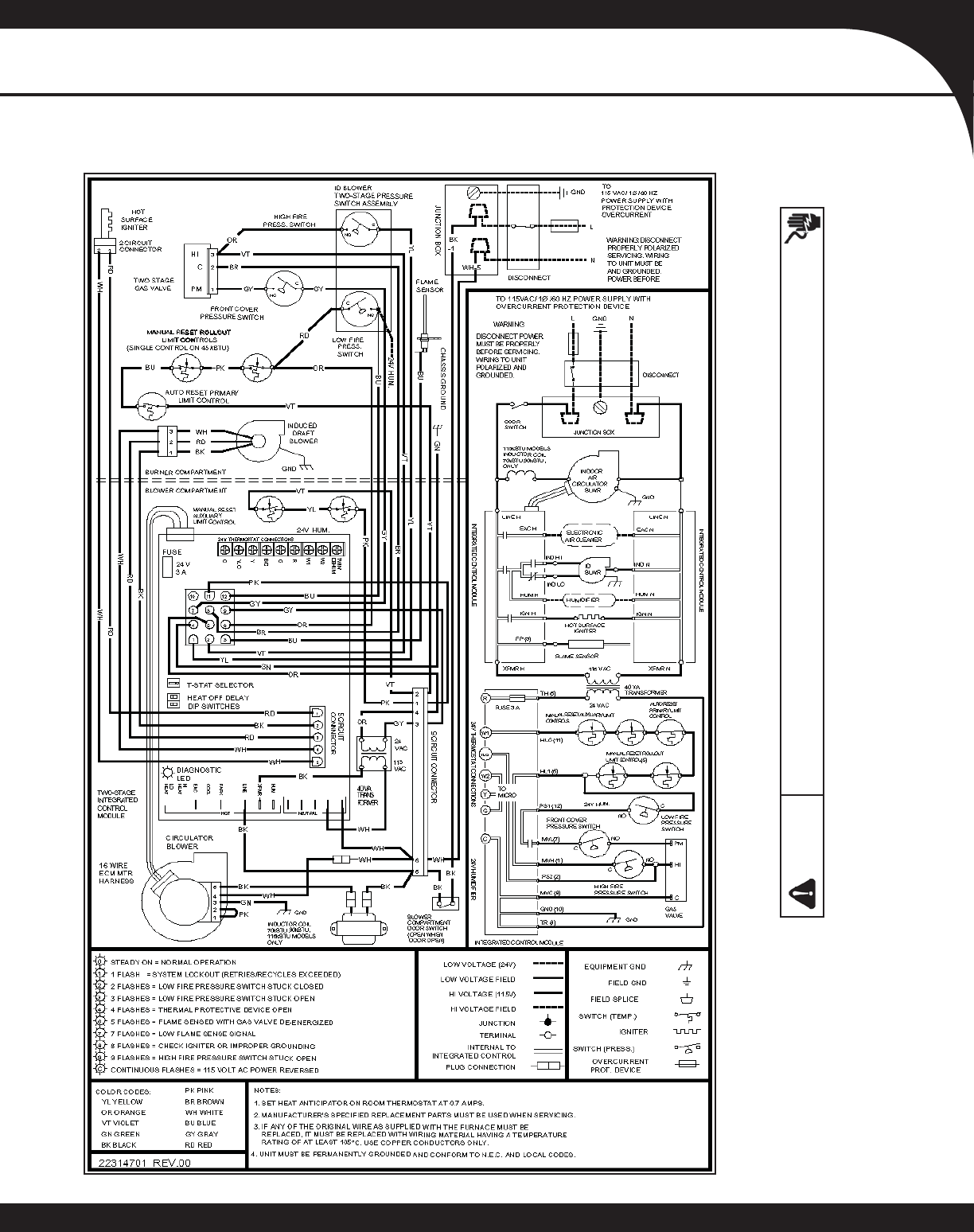
PRODUCT SPECIFICATIONS
GMV95/ GCV9 WIRING DIAGRAM
Wiring is subject to change. Always
refer to the wiring diagram on the
unit for the most up-to-date wiring
WARNING High Voltage: Disconnect all power before servicing or installing this unit. Multiple power
sources may be present. Failure to do so may cause property damage, personal injury, or death.
14 www.goodmanmfg.com SS-GMV95
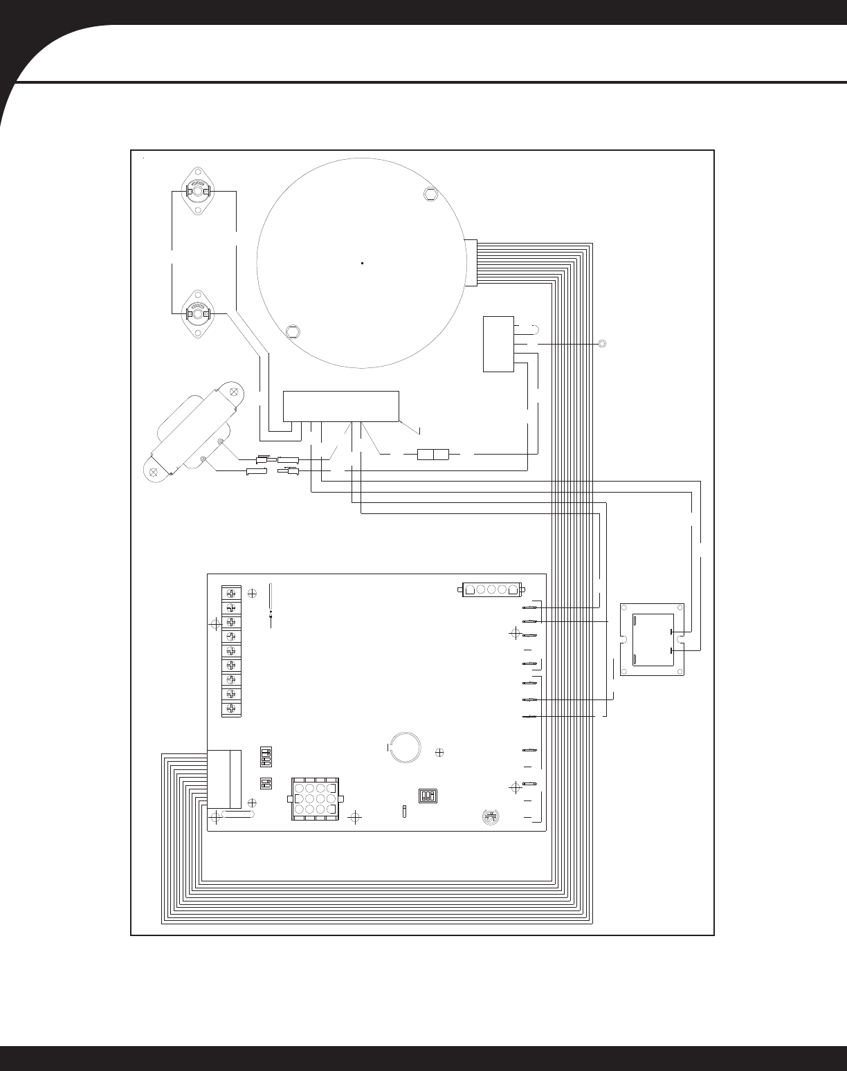
PRODUCT SPECIFICATIONS
GMV95/ GCV9 BLOWER ASSEMBLY SCHEMATIC
This schematic is for reference only. Not all wiring is as shown above.
Refer to the appropriate wiring diagram for the unit being serviced.
LOAD
LINE
HARNESS
TO MAIN
CONNECTOR
9 CIRCUIT
PIN 4
PIN 9
PIN 8
PIN 7
WHBK
BK
HOT NEUTRAL
LINE
XFMR
EAC
CIRC
HUM
HUM
XFMR
LINE
PARK
COOL
HEAT
HI
EAC
HEAT
LO
CFM
USC
WR
DEHUM
CUT FOR
1
2
3
87 4321
87 4321
Intell-Ignition
TSTAT
S4
S3
OFF
ON
S1
SINGLE
TWO
ON OFF
YL
PK
VT
HOUSING)
(SIDES OF BLOWER
AUXILIARY LIMITS
PIN 1
PIN 2
BK
WH
GN
GY
OR
BK
WH
PIN 6
SCROLL HOUSING
GROUND TO
PK
PIN5
PIN4
PIN3
PIN2
PIN1
WH
BLWR MOTOR
TO ECM
BK
WH
BK
WH
GY
OR
PIN 5
PIN 3
TRANSFORMER
INTEGRATED CONTROL MODULE
(GUVA070,090,115 MODELS ONLY)
INDUCTOR COIL
ECM BLOWER MOTOR
SS-GMV95 www.goodmanmfg.com 15
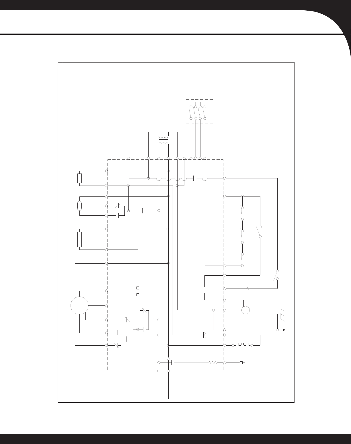
PRODUCT SPECIFICATIONS
GMV95/ GCV9 SCHEMATICS (CONT.)
MATE WITH AMP
1-480708-0
3 AMP
AUTOMOTIVE
FUSE
350550-1
SOCKETS
USING
K3
K8a
K8b
PARK
THERMOSTAT
NEU
CIRC.
W8
LO
IND
HI
IND
NEU
IND
K1
K2
HEAT
HIGH
IGN
FP
H1
C
SWITCH
PRESSURE
2ND STAGE
M
P
COM
MV
SWITCH
ROLLOUT
MVH
W2 W2
HUM
EAC NEU
EAC
AIR CLEANER
ELECTRONIC INDUCER
HUMN
HUMIDIFIER
W1
G
Y
R
W1
G
Y
B/C
TR
R
TH
24 V.A.C.
XFMRN
XFMR
BLOWER
CIRCULATOR
HLIHLO
PS1PS2
MVL
GND
IGNN
IGNITOR
PROBE
SENSOR
FLAME
SWITCH
PRESSURE
1ST STAGE
LIMIT
AUX
LIMIT
HIGH
GAS VALVE
2 STAGE
K6
COOL
HEAT
LOW
K7
Q22
1M
.0005
LINE NEU
120 VAC
LINE HOT
WR 50V61-289 INTEGRATED IGNITION CONTROL
This schematic is for reference only. Not all wiring is as shown above. Refer to the appropriate wiring diagram for the unit being serviced.
16 www.goodmanmfg.com SS-GMV95
PRODUCT SPECIFICATIONS
Goodman Manufacturing Company, L.P., reserves the right to discontinue, or change at any time, specifi cations or designs without notice
or without incurring obligations. © 2008-2009 • Goodman Manufacturing Company, L.P. • Houston, Texas • Printed in the USA.
Model Description
CHT90-120 Cooling/Heating, Mechanical
CH70TG Cooling/Heating, Digital, Non-programmable
CHSATG Cooling/Heating, Mechanical
H20TWR Heating Only, Mechanical
THERMOSTATS
A two-stage thermostat should be used with the GMV95/GCV9 furnaces. Two-stage thermostats control which ring rate is
used depending on the temperature di erence between the set point and the room temperature. A properly used two-stage
thermostat and furnace will maintain a much tighter
control of temperature than a conventional single-stage
thermostat and furnace. Two-stage furnaces have “W1”
and “W2” terminals. If the thermostat has “Y1” and “Y2”
cooling connections and a single-stage cooling system
is used, connect “Y” on the furnace control to “Y1” on
the thermostat. The table below describes two-stage
thermostats that have been con gured for use with this
furnace.
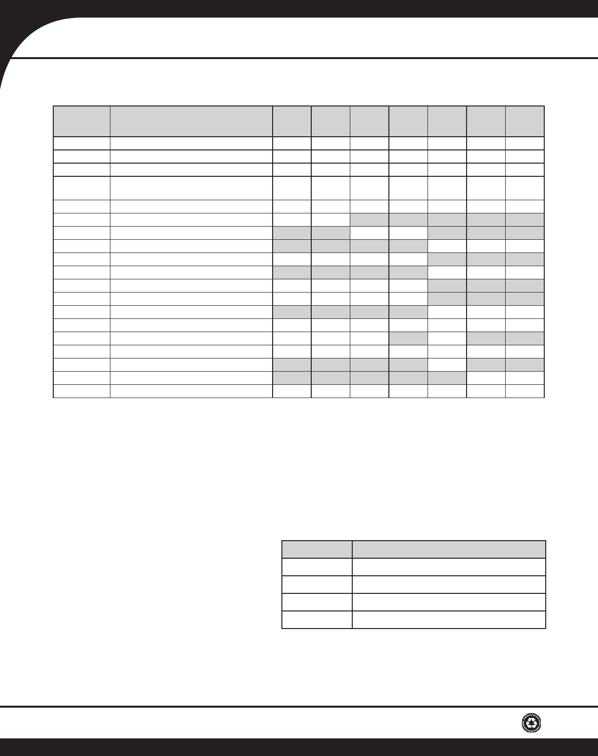
Model Description GMV95
0453BXB GMV95
0704CXB GMV95
0905DXB GMV95
1155DXB GCV9
0704CXB GCV9
0905DXB GCV9
1155DXB
LPM-03B LP Conversion Kit (Gas Valve) 1 1 1 1 1 1
LPM-05 LP Conversion Kit (Springs & Orifi ce) 1 1 1 1 1 1
GSAS Electronic Air Cleaners (-10, -11, -12 or -18) √√√√√√
GMU Media Air Cleaners
(1620, 2020, 1625 or 2025) √√√√√√
DEHUM1 Dehumidistat √√√√√√
HAPS28 High-Altitude Pressure Switch Kit 2 2
HAPS29 High-Altitude Pressure Switch Kit 2 2
HAPS 31 High-Altitude Pressure Switch Kit 2 2
HALP11 High-Altitude Propane Gas Kit 2 2 2 2
HALP 13 High-Altitude Propane Gas Kit 2 2
HANG 13 High-Altitude Natural Gas Kit 3 3 3 3
HANG 14 High-Altitude Natural Gas Kit 4 4 4 4
HANG 16 High-Altitude Natural Gas Kit 2 2
EFR01 External Filter Rack √√√√√√
DCVK-20 Horizontal/Vertical Concentric Vent Kit (2”) √√√ √
DCVK-30 Horizontal/Vertical Concentric Vent Kit (3”) √√√√√√
CFB21 Downfl ow Floor Base √
CFB24 Downfl ow Floor Base √
017K00000S Flush-mount vent kit √√√√√√
1– All Models up to 7,000’ 2– 7,001’ to 11,000’ 3– 7,001’ to 9,000’ 4– 9,001’ to 11,000’
Note: All installations above 7,000’ require a pressure switch change. For installation in Canada, gas furnaces are certifi ed
only to 4,500’.
ACCESSORIES
