Graco Inc 310548G Users Manual GH 200 Sprayer Repair (english)
GH 200 to the manual dede42dc-b7b1-4db5-aba4-ee91586b548c
2015-02-09
: Graco-Inc Graco-Inc-310548G-Users-Manual-561328 graco-inc-310548g-users-manual-561328 graco-inc pdf
Open the PDF directly: View PDF ![]() .
.
Page Count: 24
Repair
GRACO INC. P.O. BOX 1441 MINNEAPOLIS, MN 55440- 1441
Copyright 2002, Graco Inc. is registered to I.S. EN ISO 9001
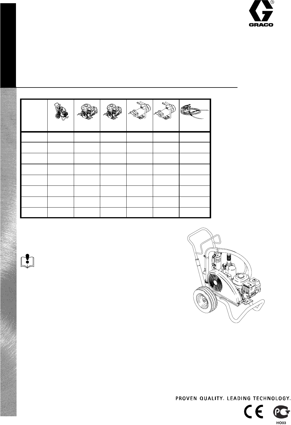
GHt200 Sprayer 310548G
Read warnings and instructions.
Contents
Warnings 2................................
General Repair Information 4................
Maintenance 5.............................
Troubleshooting 6..........................
Hydraulic Pump 7..........................
Fan Belt 9.................................
Engine 10.................................
Hydraulic Motor Yoke 11....................
Oil/Filter Change 13........................
Displacement Pump 14.....................
GH200 Sprayers Parts Drawing 16...........
GH200 Sprayers Parts List 19...............
GH200 Sprayers with Spray Gun and Hoses 22
Technical Data 23..........................
Graco Warranty 24.........................
Related Manuals
Operation 309548.........
Displacement Pump 309277
Spray Gun 309639........
Spray Tip 309640..........
Drain Valve 308961.......
Electric Motor 309553......
233940 ti2273a
5.5 HP 6.5 HP CSA/UL
233940 n n
233941 n n n
233942 n n n
233943 n n n
245693 n
246126 n
246253 n
246311 n
3300 psi (227 bar, 22.7 MPa) Maximum Working Pressure
All models not available in all countries.
3105482
WARNING
FIRE AND EXPLOSION HAZARD
Flammable fumes, such as solvent and paint fumes, in work area can ignite or explode. To help pre-
vent fire and explosion:
DUse equipment only in well ventilated area.
DDo not fill fuel tank while engine is running or hot; shut off engine and let it cool. Fuel is flammable
and can ignite or explode if spilled on hot surface.
DWhen flammable liquid is sprayed or used for flushing or cleaning, keep sprayer at least 20 feet (6
m) away from explosive vapors.
DEliminate all ignition sources; such as pilot lights, cigarettes, portable electric lamps, and plastic
drop cloths (potential static arc).
DKeep work area free of debris, including solvent, rags and gasoline.
DDo not plug or unplug power cords, or turn power or light switches on or off when flammable fumes
are present.
DGround equipment and conductive objects in work area. See Grounding instructions.
DUse only grounded hoses.
DHold gun firmly to side of grounded pail when triggering into pail.
DIf there is static sparking or you feel a shock, stop operation immediately. Do not use equipment
until you identify and correct the problem.
INJECTION HAZARD
High--pressure fluid from gun, hose leaks, or ruptured components will pierce skin. This may look like
just a cut, but it is a serious injury that can result in amputation. Get immediate medical attention.
DDo not point gun at anyone or at any part of the body.
DDo not put your hand over the spray tip.
DDo not stop or deflect leaks with your hand, body, glove, or rag.
DDo not spray without tip guard and trigger guard installed.
DEngage trigger lock when not spraying.
DFollow Pressure Relief Procedure in this manual, when you stop spraying and before cleaning,
checking, or servicing equipment.
PRESSURIZED EQUIPMENT HAZARD
Fluid from the gun/dispense valve, leaks, or ruptured components can splash in the eyes or on skin
and cause serious injury.
DFollow Pressure Relief Procedure in this manual, when you stop spraying and before cleaning,
checking, or servicing equipment.
DTighten all fluid connections before operating the equipment.
DCheck hoses, tubes, and couplings daily. Replace worn or damaged parts immediately.
MOVING PARTS HAZARD
Moving parts can pinch or amputate fingers and other body parts.
DKeep clear of moving parts.
DDo not operate equipment with protective guards or covers removed.
DPressurized equipment can start without warning. Before checking, moving, or servicing equip-
ment, follow the Pressure Relief Procedure in this manual. Disconnect power or air supply.
3310548
WARNING
EQUIPMENT MISUSE HAZARD
Misuse can cause death or serious injury.
DDo not exceed the maximum working pressure or temperature rating of the lowest rated system
component. See Technical Data in all equipment manuals.
DUse fluids and solvents that are compatible with equipment wetted parts. See Technical Data in all
equipment manuals. Read fluid and solvent manufacturer’s warnings.
DCheck equipment daily. Repair or replace worn or damaged parts immediately.
DDo not alter or modify equipment.
DFor professional use only.
DUse equipment only for its intended purpose. Call your Graco distributor for information.
DRoute hoses and cables away from traffic areas, sharp edges, moving parts, and hot surfaces.
DDo not use hoses to pull equipment.
DComply with all applicable safety regulations.
PRESSURIZED ALUMINUM PARTS HAZARD
Do not use 1,1,1--trichloroethane, methylene chloride, other halogenated hydrocarbon solvents or
fluids containing such solvents in pressurized aluminum equipment. Such use can cause serious
chemical reaction and equipment rupture, and result in death, serious injury, and property damage.
SUCTION HAZARD
Never place hands near the pump fluid inlet when pump is operating or pressurized. Powerful suction
could cause serious injury.
CARBON MONOXIDE HAZARD
Exhaust contains poisonous carbon monoxide, which is colorless and odorless. Breathing carbon
monoxide can cause death. Do not operate in an enclosed area.
TOXIC FLUID OR FUMES HAZARD
Toxic fluids or fumes can cause serious injury or death if splashed in the eyes or on skin, inhaled, or
swallowed.
DRead MSDS’s to know the specific hazards of the fluids you are using.
DStore hazardous fluid in approved containers, and dispose of it according to applicable guidelines.
BURN HAZARD
Equipment surfaces and fluid that’s heated can become very hot during operation. To avoid severe
burns, do not touch hot fluid or equipment. Wait until equipment/fluid has cooled completely.
PERSONAL PROTECTIVE EQUIPMENT
You must wear appropriate protective equipment when operating, servicing, or when in the operating
area of the equipment to help protect you from serious injury, including eye injury, inhalation of toxic
fumes, burns, and hearing loss. This equipment includes but is not limited to:
DProtective eyewear.
DClothing and respirator as recommended by the fluid and solvent manufacturer.
DGloves.
DHearing protection.
RECOIL HAZARD
Brace yourself; gun may recoil when triggered and cause you to fall, which could cause serious injury.
3105484
General Repair Information
WARNING
MOVING PARTS HAZARD
To reduce risk of serious injury, do not
touch moving parts with fingers or tools
while testing repair. Shut off sprayer
when repairing. Install all covers, gas-
kets, screws and washers before operat-
ing sprayer.
1. Keep all screws, nuts, washers, gaskets, and
electrical fittings removed during repair proce-
dures. These parts are not normally provided with
replacement assemblies.
2. Test repair after problem is corrected.
3. If sprayer does not operate properly,review
repair procedure to verify procedure was done
correctly. If necessary, see Troubleshooting Guide,
page 6, for other possible solutions.
WARNING
HOT SURFACES HAZARD
EXPLOSION HAZARD
Hydraulic system and engine may be
very hot during operation and could burn
skin if touched.
Flammable materials spilled on hot
engine could cause fire or explosion.
Have belt guard in place during opera-
tion to reduce risk of pinching or loss of
fingers.
4. Install belt guard before operation of sprayer
and replace if damaged. Belt guard reduces risk of
pinching and loss of fingers; see preceding
WARNING.
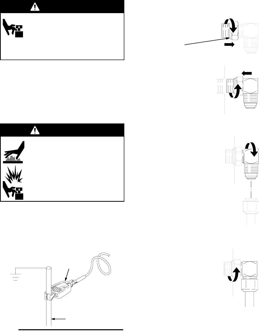
Grounding
Ground sprayer with grounding clamp to earth ground for
safe sprayer operation. Fig. 1.
Fig. 1 06250
water pipe, steel
sign post, or metal
light pole
grounding
clamp
SAE O-Ring Installation
1. Unscrew lock nut to touch fitting.
2. Lubricate o-ring
3. Screw in fitting hand tight.
4. Unscrew fitting until oriented properly.
5. Tighten lock nut to indicated torque.
(Make sure washer is seated
properly without pinching o-ring).
5310548
Maintenance
WARNING
INJECTION HAZARD
The system pressure must be manually
relieved to prevent the system from
starting or spraying accidentally. Fluid
under high pressure can be injected through the
skin and cause serious injury. To reduce the risk of
an injury from injection, splashing fluid, or moving
parts, follow the Pressure Relief Procedure
whenever you:
Dareinstructedtorelievethepressure,
Dstop spraying,
Dcheck or service any of the system equipment,
Dor install or clean the spray tip.
Pressure Relief Procedure
1. Lock gun trigger safety.
2. Turn engine ON/OFF switch to OFF.
3. Move pump valve to OFF (down) and turn pres-
sure control knob fully counterclockwise.
4. Unlock trigger safety. Hold metal part of gun firmly
to side of grounded metal pail, and trigger gun to
relieve pressure.
5. Lock gun trigger safety.
6. Open pressure drain valve. Leave valve open until
ready to spray again.
If you suspect that the spray tip or hose is completely
clogged, or that pressure has not been fully relieved
after following the steps above, VERY SLOWLY
loosen tip guard retaining nut or hose end coupling to
relieve pressure gradually, then loosen completely.
Now clear tip or hose.
C
A
UTION
For detailed engine maintenance and specifications,
refer to separate Honda Engines Owner’s Manual,
supplied.
DAILY: Check engine oil level and fill as necessary.
DAILY: Check hydraulic oil level and fill as neces-
sary.
DAILY: Check hose for wear and damage.
DAILY: Check gun safety for proper operation.
DAILY: Check pressure drain valve for proper opera-
tion.
DAILY: Check and fill the gas tank.
DAILY: Check that displacement pump is tight.
DAILY: Check level of TSL in displacement pump
packing nut. Fill nut, if necessary. Keep TSL in nut to
help prevent fluid buildup on piston rod and premature
wear of packings and pump corrosion.
AFTER THE FIRST 20 HOURS OF OPERATION:
Drain engine oil and refill with clean oil. Reference
Honda Engines Owner’s Manual for correct oil viscos-
ity.
WEEKLY: Remove engine air filter cover and clean
element. Replace element, if necessary. If operating in
an unusually dusty environment: check filter daily and
replace, if necessary.
Replacement elements can be purchased from your
local HONDA dealer.
WEEKLY/DAILY: Remove any debris or media from
hydraulic rod.
AFTER EACH 100 HOURS OF OPERATION:
Change engine oil. Reference Honda Engines Owner’s
Manual for correct oil viscosity.
SEMI-ANNUALLY:
Check belt wear, page 9; replace if necessary.
YEARLY OR 2000 HOURS:
Replace hydraulic oil and filter element with Graco
hydraulic oil 169236 (5 gallon/20 liter) or 207428 (1
gallon/3.8 liter) and filter element 246173; page 6.
Replace belt.
SPARK PLUG: Use only BPR6ES (NGK) or
W20EPR--U (NIPPONDENSO) plug. Gap plug to
0.028 to 0.031 in. (0.7 to 0.8 mm). Use spark plug
wrench when installing and removing plug.

3105486
Troubleshooting
Relieve pressure;page 5.
PROBLEM CAUSE SOLUTION
Gas engine pulls hard (won’t start) Hydraulic pressure is too high Turn hydraulic pressure knob counterclockwise
to lowest setting
Gas engine will not start Switch OFF, low oil, no gasoline Consult engine manual, supplied
Gas engine doesn’t work properly
Elevation
Consult engine manual, supplied.
Refer to 6.5 HP Engine Repair Kit, 246311.
Gas engine operates, but displace-
ment pump doesn’t operate
Pump valve is OFF Set pump valve ON
Pressure setting too low Increase pressure. See manual 309548
Displacement pump outlet filter (if
used) is dirty or clogged
Clean filter
Tip or tip filter (if used) is clogged Remove tip and/or filter and clean
Hydraulic fluid too low Shut off sprayer. Add fluid*. See page 5.
Belt worn or broken Replace.
Hydraulic pump worn or damaged Bring sprayer to Graco distributor for repair
Dried paint seized paint pump rod Service pump. See manual 309277.
Hydraulic motor not shifting Set pump valve OFF. Turn pressure down.
Turn engine OFF. Pry rod up or down until hy-
draulic motor shifts.
Displacement pump operates, but
output is low on upstroke
Piston ball check not seating properly.
Piston packings worn or damaged.
Service piston ball check. See manual 309277.
Replace packings. See manual 309277.
Displacement pump operates but
output is low on downstroke and/or
on both strokes
Piston packings worn or damaged.
Intake valve ball check not seating
properly.
Suction tube air leak
Tighten packing nut or replace packings. See
manual 309277.
Service intake valve ball check. See manual
309277.
Tighten suction tube
Paint leaks and runs over side of
wet-cup
Loose wet-cup
Throat packings worn or damaged
Tighten packing nut enough to stop leakage
Replace packings. See manual 309277
Excessive leakage around hydraulic
motor piston rod wiper
Piston rod seal worn or damaged Replace these parts.
Fluid delivery is low Pressure setting too low
Displacement pump outlet filter (if
used) is dirty or clogged
Intake line to pump inlet is not tight
Hydraulic motor is worn or damaged
Large pressure drop in fluid hose
Increase pressure. See manual 309548.
Clean filter
Tighten
Bring sprayer to Graco distributor for repair
Use larger diameter or shorter hose
The sprayer overheats Paint buildup on hydraulic components Clean
Oil level is low Fill with oil. See page 5.
Spitting from gun Air in fluid pump or hose Check for loose connections on siphon
assembly, tighten, then reprime pump
Loose intake suction Tighten
Fluid supply is low or empty Refill supply container
Excessive hydraulic pump noise Low hydraulic fluid level Shut off sprayer. Add fluid*. See page 5.
*Check hydraulic fluid level often. Do not allow it to become too low. Use only Graco approved hydraulic fluid, page 5.

7310548
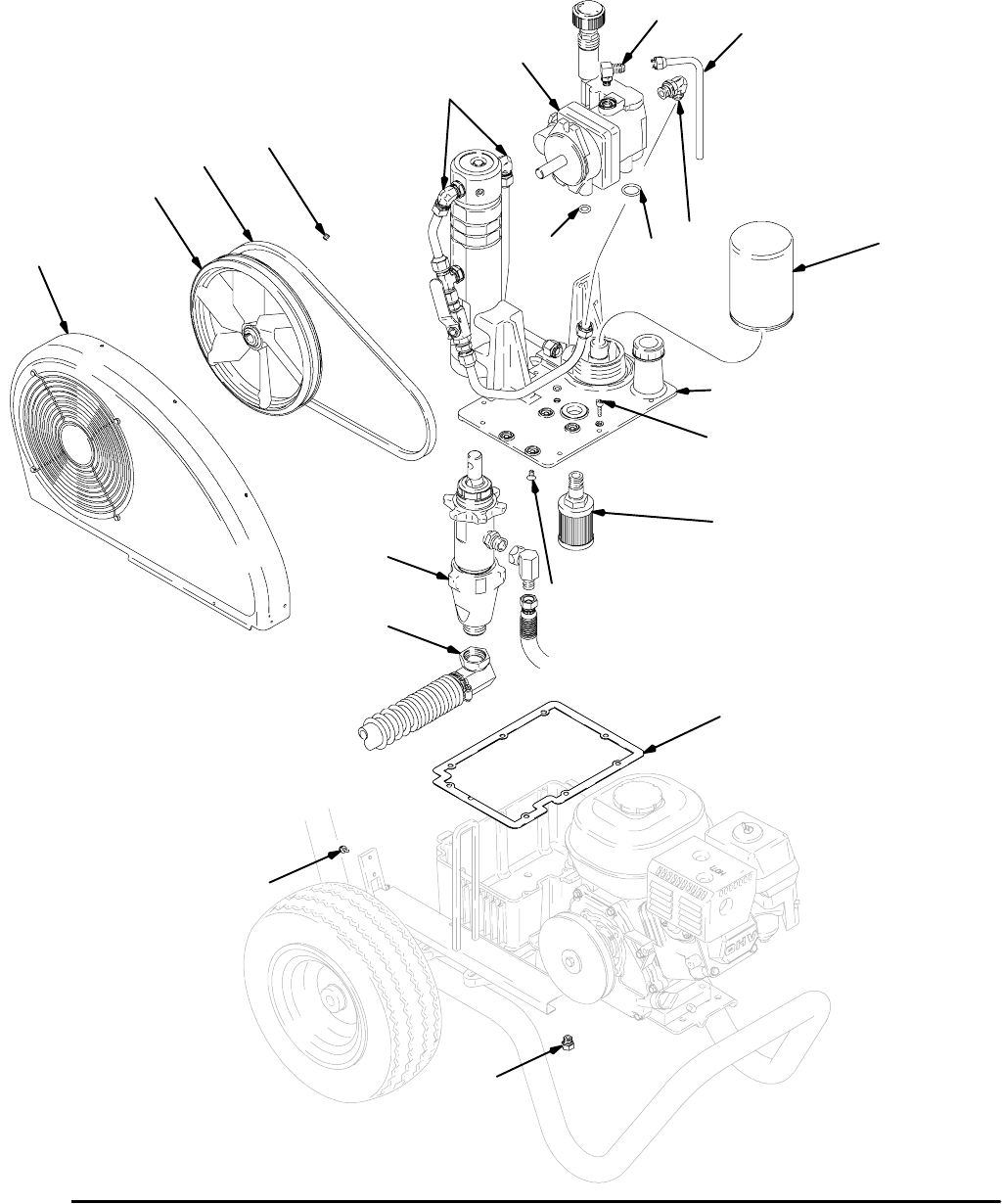
Hydraulic Pump
Removal
1. Relieve pressure;page 5.
Let hydraulic system cool before beginning ser-
vice.
2. Place drip pan or rags under sprayer to catch
hydraulic oil that leaks out during repair.
3. Remove drain plug (40) and oil filter (47) and allow
hydraulic oil to drain.
4. Fig. 2. Disconnect suction tube (114).
5. Disconnect paint pump (111).
6. Remove two screws (115a) and belt guard (117).
7. Raise motor and remove belt (44).
8. Remove two set screws (133) and fan pulley (96).
9. Remove case drain tube (97).
10. Remove elbow (22).
11. Remove eight screws (27) reservoir cover (68)
filter assembly (A) and gasket (62).
12. Remove four screws (5) and hydraulic pump (98)
from reservoir (69).
Installation
1. Install hydraulic pump (98) in reservoir (69) with
four screws (5); torque 100 in-lb (11 N·m).
2. Install gasket (62) and reservoir cover (68) with
eight screws (27); torque 90 in-lb (10 N·m).
3. Install elbow (22); torque to 15 ft-lb (20.3 N·m).
4. Install case drain tube (97); torque to 25 ft-lb
(33.9 N·m).
5. Install fan pulley (96) with two set screws (133).
6. Raise motor and install belt (44).
7. Install belt guard (117) with two screws (115a).
8. Connect paint pump (111).
9. Fig. 2. Connect suction tube (114).
10. Install drain plug (40); torque to 110 in-lb
(12.4 N·m). Install oil filter (47); tighten 3/4 turn
after gasket contacts base. Fill with Graco hydrau-
lic oil, page 5.
11. Start up and allow pump to operate at low pres-
sure for approximately 5 minutes to purge all air.
3105488
ti2267a
98
96
133
68
27
5
16
Fig. 2 ti2267a
128
44
117
62
111
114
A
40
47
58
17
37
97
22
9310548
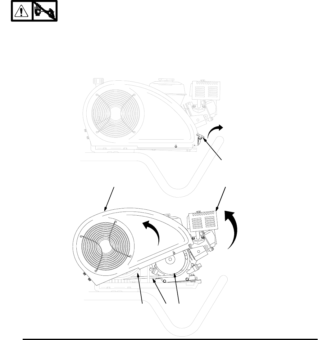
Fan Belt
Removal
1. Relieve pressure;page 5.
2. Fig. 3. Unlatch T-handle (125).
3. Rotate belt guard (117) up.
4. Lift engine (119) up to remove tension on belt (44).
5. Remove belt from pulley (43) and fan (96).
Installation
1. Thread belt (44) around drive pulley (43) and fan
pulley (96).
2. Let engine (119) down to put tension on belt.
3. Rotate belt guard (117) down.
4. Latch T-handle (125).
96 44
Fig. 3
119
43
ti2268a
125
119117
31054810
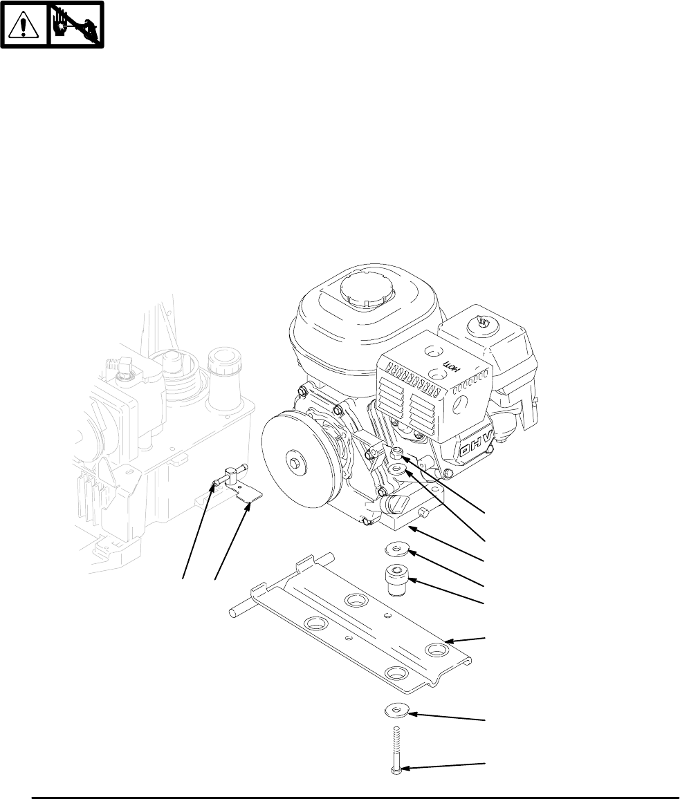
Engine
Removal
NOTE: All service to the engine must be performed by
an authorized HONDA dealer.
1. Relieve pressure;page 5.
2. Fig. 4. Loosen motor clamp (55). Swing motor
retainer bracket (105) out.
3. Do Fan Belt, Removal; page 9.
4. Remove engine (119) and rocker plate (99) from
sprayer.
5. Remove four screws (23), washers (7) and nuts
(24) and remove rocker plate (99), dampeners
(153) and washers (154) from engine (119).
Installation
1. Install rocker plate (99), dampeners (153) and
washers (154) on engine (119) with four screws
(23), washers (7) and nuts (24); torque to 125 in-lb
(14.1 N·m).
2. Install engine and rocker plate (99) on sprayer.
3. Do Fan Belt, Removal; page 9.
4. Swing motor retainer bracket (105) in. Tighten
motor clamp (55).
ti2269a
Fig. 4
119
99
23
154
105
24
55
7
154
153
11310548
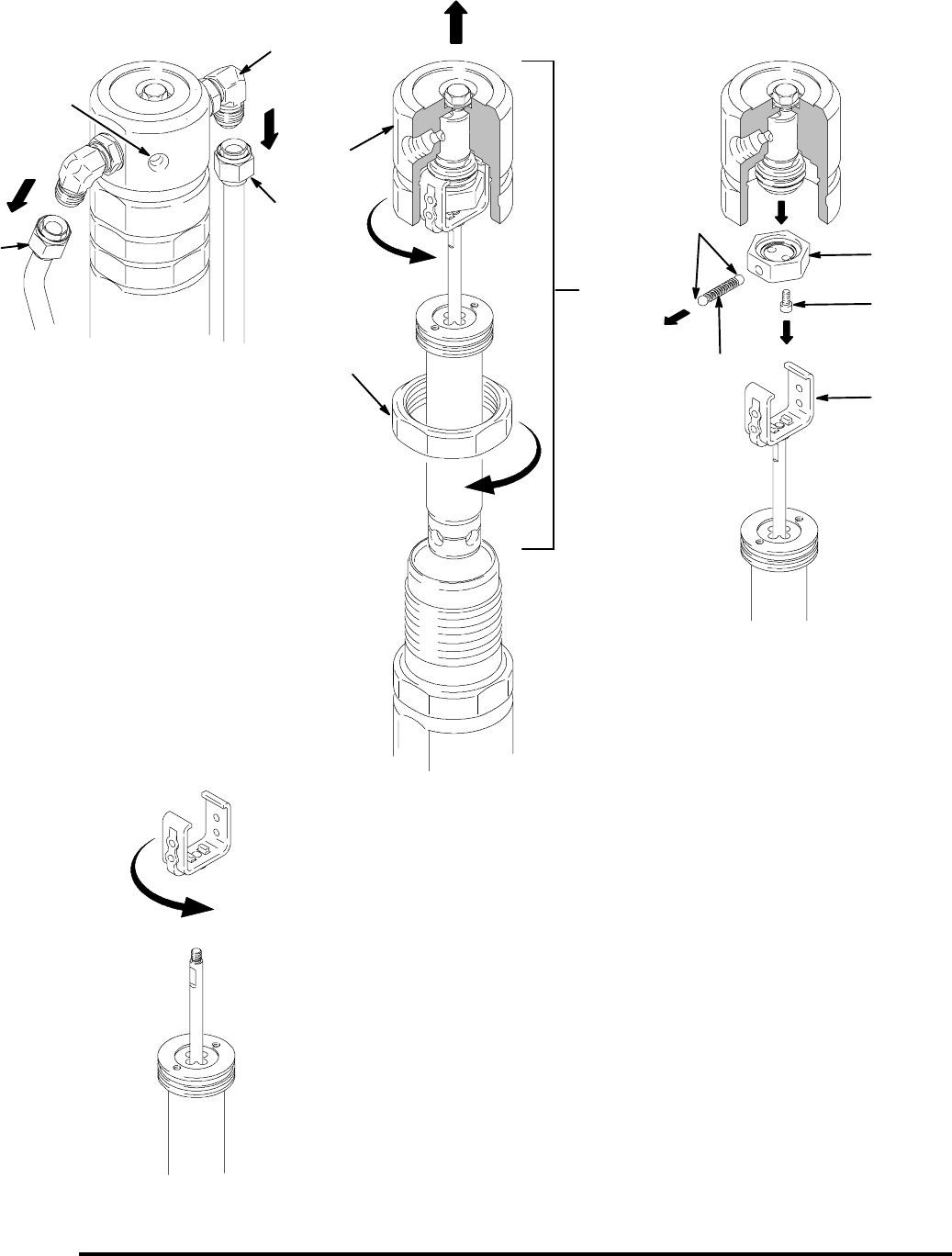
Hydraulic Motor Yoke
Removal
1. Relieve pressure;page 5.
2. Place drip pan or rags under sprayer to catch
hydraulic oil that leaks out during repair.
3. Remove pump pin (21) and retainer clip (120),
page 14.
4. Fig. 5. Remove hydraulic lines (93, 95) from fit-
tings (16) at top left and right side of hydraulic
motor.
5. Loosen jam nut (65).
6. Unscrew and remove hydraulic motor cap (64).
7. Slide piston rod/hydraulic motor cap assembly (A)
from hydraulic motor cylinder.
8. Remove yoke (78).
a. Fig. 5. Clamp hydraulic motor cap in vise with
hydraulic motor piston rod facing up.
b. Use shortened Allen wrench to remove two
screws (13) from spring retainer (83). Remove
yoke, spring retainer, piston and trip rod as-
sembly from hydraulic motor cap.
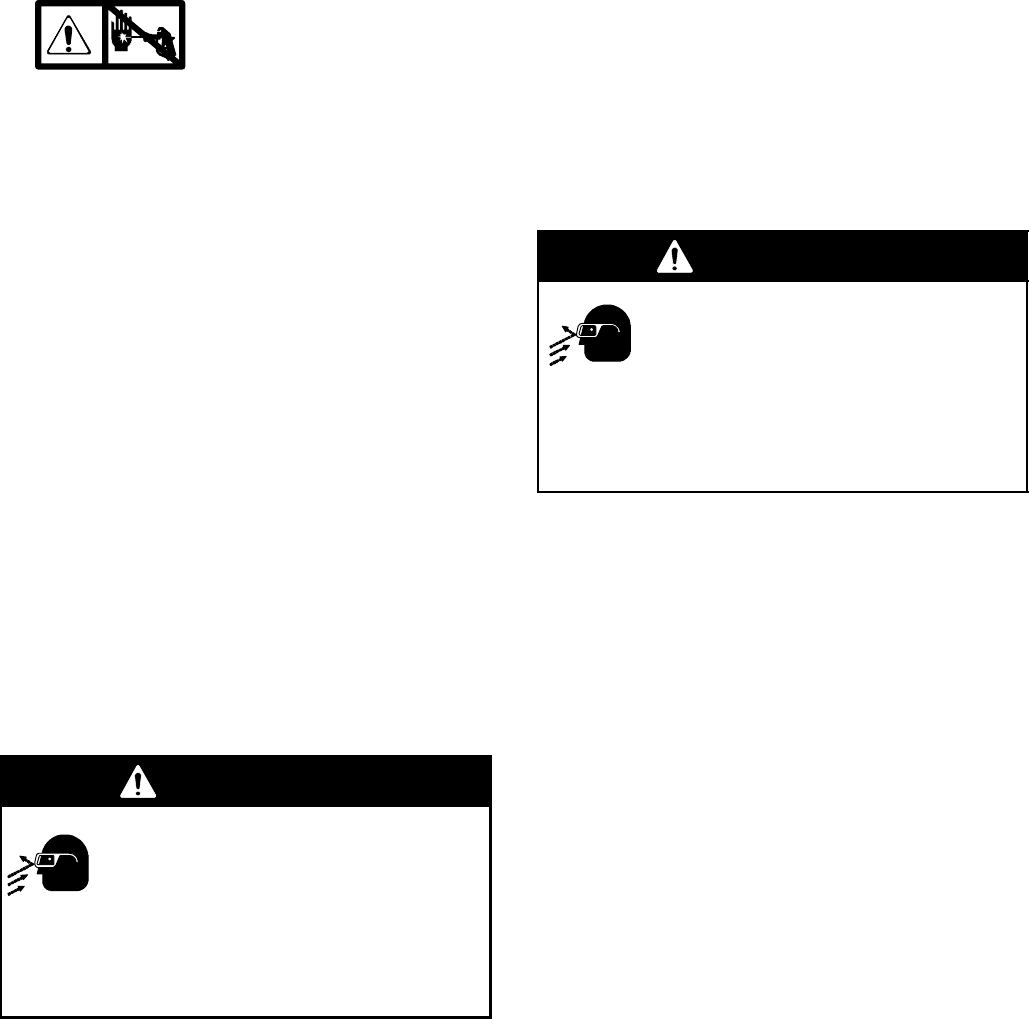
WARNING
Flying Parts Hazard
Detent spring has high energy potential.
If detent spring is released without due
care detent spring and balls could fly into
the eyes of the disassembler. Wear safety glasses
when removing or installing detent spring and balls.
Failure to wear safety glasses when removing
detent spring could result in eye injury or blindness.
c. Cover spring retainer (83) with a rag to contain
detent spring (20) and balls (8) when they are
removed from yoke. Remove detent balls and
spring. Remove spring retainer.
d. Put yoke in vise and remove piston rod as-
sembly from yoke.
Installation
1. Assemble yoke (78) to trip rod (60).
a. Clean threads with primer or chlorinated sol-
vent and let dry 3 to 4 minutes. Apply thread
sealant to female threads of yoke. Clamp yoke
in vise and, with wrench on flats of trip rod,
screw trip rod into yoke. Torque to 55 in-lb (6.2
N·m). Allow thread sealant to dry for 3 hours
prior to contact with hydraulic fluid.
WARNING
Flying Parts Hazard
Detent spring has high energy potential.
If detent spring is released without due
care detent spring and balls could fly into
the eyes of the disassembler. Wear safety glasses
when removing or installing detent spring and balls.
Failure to wear safety glasses when removing
detent spring could result in eye injury or blindness.
b. Fig. 5. Put hydraulic motor cap (64) in vise.
c. Install yoke, spring retainer, piston and trip rod
assembly in hydraulic motor cap. Use short-
ened Allen wrench to install two screws (13) in
spring retainer to secure piston rod assembly
to hydraulic motor cap.
2. Slide piston rod assembly (A) into hydraulic motor
cylinder.
3. Screw down hydraulic motor cap (64). Unscrew
hydraulic motor cap until inlet and outlet align with
hydraulic line fittings and test hole in hydraulic
motor cap points toward belt guard (117).
4. Torque jam nut (65) against hydraulic motor cap
(64) to 150 ft-lb (17 N·m).
5. Fig. 5. Install hydraulic lines (93, 95) to fittings (16)
to top left and right side of hydraulic motor; torque
to 40 ft-lb (54.2 N·m).
6. Pull start rope slowly to align pin holes of hydraulic
motor and displacement pump (111). Connect with
pump pin (21); install retainer clip (120), page 14.
7. Start engine and operate pump for 30 seconds.
Turn engine OFF. Check hydraulic oil level and fill
with Graco hydraulic oil, page 5.
31054812
Fi
g
.5
78
64
93
95
A13
83
65
8
20
5. a. 5. b. 5. c.
5. d.
16
test hole
ti3476a
13310548
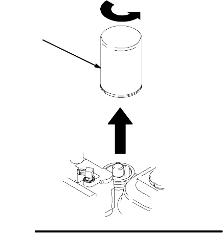
Oil/Filter Change
Removal
1. Fig. 6. Place drip pan or rags under sprayer to
catch hydraulic oil that drains out.
2. Remove drain plug (40). Allow hydraulic oil to
drain.
3. Unscrew filter (47) slowly -- oil runs into groove
and drains out rear.
Installation
1. Install drain plug (40) and oil filter (47). Tighten oil
filter 3/4 turn after gasket contacts base.
2. Fill with four quarts of Graco hydraulic oil 169236
(5 gallon/20 liter) or 207428 (1 gallon/3.8 liter)
3. Check oil level. Fig. 6
ti2271a
47
31054814
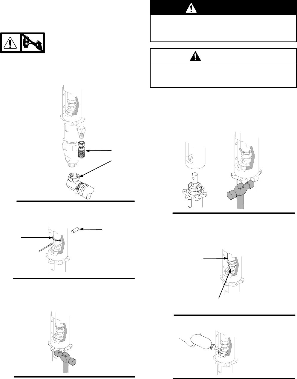
Displacement Pump
See manual 309277 for pump repair instructions.
Removal
1. Flush pump.
2. Relieve pressure;page 5.
3. Fig. 7. Remove suction tube (114) and paint hose
(63) (remove at swivel end).
Fig. 7 ti2272a
63
114
4. Fig. 8. Push retaining spring up; push out pin (21).
Fig. 8
21
ti2272a
120
5. Fig. 9. Loosen jam nut. Unscrew pump.
Fig. 9 ti2272a
Installation
WARNING
If pin works loose, parts could break off and project
through the air and result in serious injury or prop-
erty damage. Make sure pin is properly installed.
C
A
UTION
DIf the pump jam nut loosens during operation, the
threads of the bearing housing and drive train will
be damaged. Tighten jam nut as specified.
1. Fig. 10. Screw jam nut to bottom of pump threads.
Screw pump completely into manifold. Unscrew
pump from manifold until pump outlet aligns with
hose. Hand tighten jam nut, then tap 1/8 to 1/4
turn with hammer or torque to 200 ft-lb (270 N·m).
Fig. 10 ti2272a
2. Fig. 11. Slowly pull engine starter rope until pump
rod pin hole is aligned with hydraulic rod hole.
Fig. 8. Push pin (21) into hole. Push retaining
spring (120) into groove.
Fig. 11 ti2272a
pump
rod
hydraulic
rod
Fig. 12. Fill packing nut with Graco TSL.
Fig. 12 ti2272a

15310548
Notes
31054816
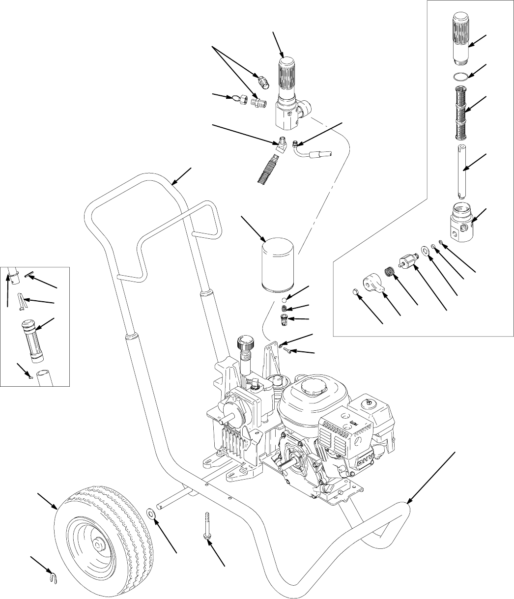
ti2264a
Parts Drawing -- GH200 Sprayers
108
113
122
121
70
47
48
54
39
112
35
19
81
75
9
116
49
100
132
329
328 327
326
325324
330
317
320
319
318
321
27
6
103
17310548
Parts List -- GH200 Sprayers
Ref. Part Description Qty. Ref. Part Description Qty.
6 100016 WASHER, lock 12
9 100084 BALL 1
19 108068 PIN, spring straight 2
35 112827 BUTTON, snap 2
39 116399 WHEEL, pneumatic, 13 in. 2
47 246173 FILTER, oil 1
48 116923 SCREW, hex head 4
49 116967 SPRING 1
54 117365 WASHER 2
70 15B563 CLIP, retainer 2
75 183350 WASHER 2
81 192027 SLEEVE, cart 2
100 198841 HOUSING, pressure 1
108 237479 CAP, filter 1
112 245275 HANDLE, cart 1
116 245917 FRAME, cart, GH 200 1
113 245323 FILTER, assy, paint 1
121 116756 FITTING, elbow, street 1
122 162485 NIPPLE, adapter 3
132 109032 SCREW, mach, pnh 4
133 100002 SCREW, set, sch 2
317# 196675 BOWL, filter 1
318# 243984 FILTER, fluid 1
319# 196786 DIFFUSER, tube 1
320# 104361 O-RING 1
321# 15A766 HOUSING, filter 1
324§ 193710 SEAL, seat valve 1
325§ 193709 SEAT, valve 1
326§ 114797 GASKET 1
327§ 245103 VALVE, drain 1
328§ 115830 SPRING 1
329§ 194102 HANDLE, valve 1
330§ 114688 NUT, cap 1
YDANGER and WARNING labels are available at no charge.
#Included in Manifold Kit 245323
§Included in Drain Valve Kit 245103
31054818
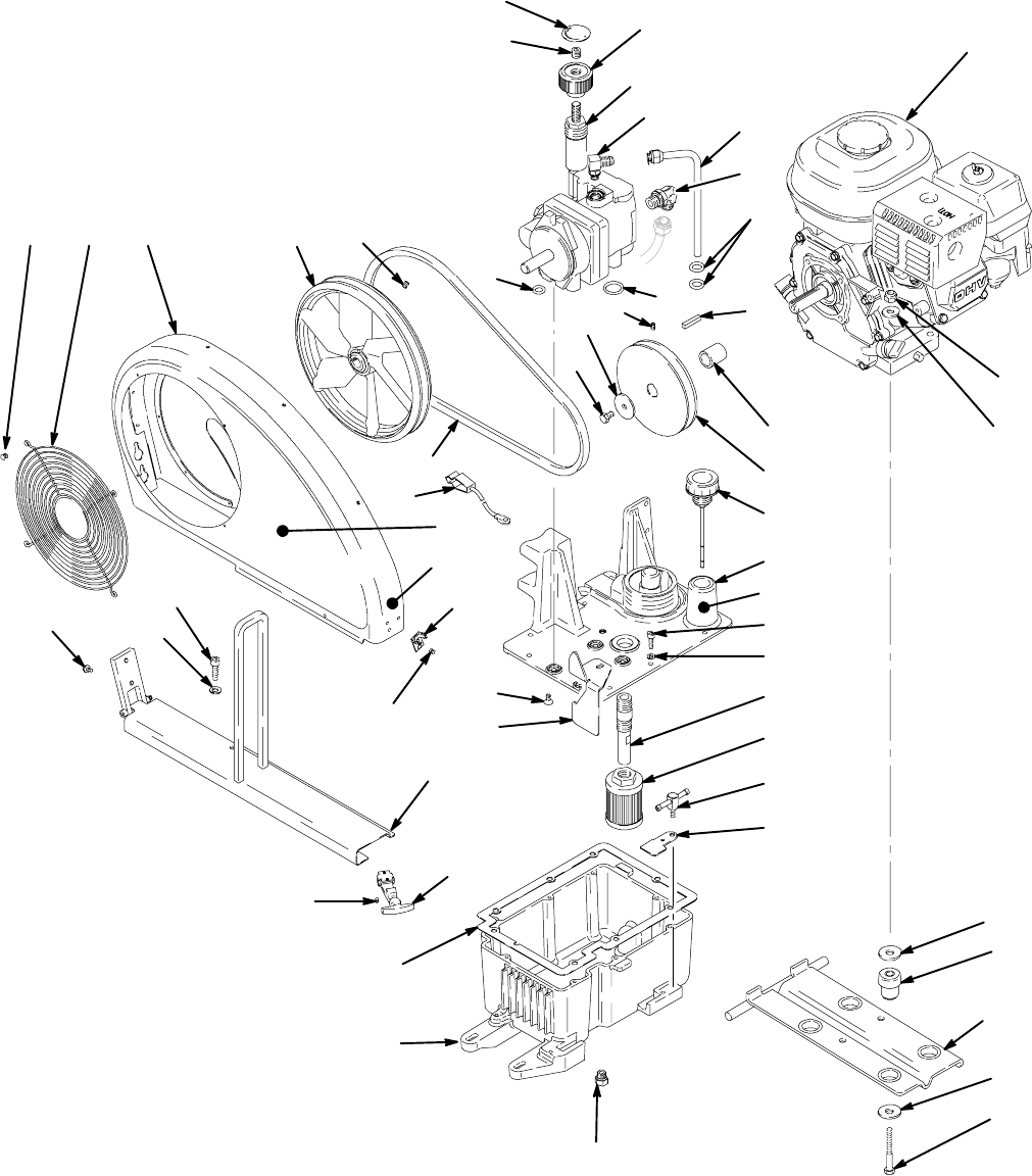
ti2265a
ti2265a
Parts Drawing -- GH200 Sprayers
27
97
6
117 13396
119
44
99
24
106
30
34
43
154
23
125
115
56
52
98
10
22
126
58
140
37
40
46
55
105
5102
27
6
131
45
68
62
69
130
115a
125
139
101
155
133
154
153
130
148 51
17
7
109
19310548
Parts List -- GH200 Sprayers
Ref. Part Description Qty. Ref. Part Description Qty.
5 117471 SCREW, 1/4--20 flat head mach 4
6 100016 WASHER, lock 12
7 100023 WASHER, flat 4
10 117560 SCREW, set 1
17 107188 O-RING 4
22 110792 ELBOW, male, 90 deg 1
23 113664 SCREW, flange, hex 4
24 110838 NUT, lock 4
27 112166 SCREW, cap, socket hh 12
30 108842 SCREW, cap, hex hd 1
34 112717 WASHER 1
37 116793 FITTING, elbow, hydraulic 1
40 116754 PLUG, hex head, hydraulic 1
43 116908 PULLEY, 5.50 in. 1
44 116914 BELT 1
45 116915 CAP, breather filler 1
46 116919 FILTER, hydraulic, suction 1
51 117284 GRILL, fan guard 1
52 15B438 KNOB, pressure 1
55 246327 KIT, motor clamp 1
56 154594 PACKING, o-ring 2
58 156401 PACKING, o-ring 1
62 246172 GASKET, reservoir 1
69 15C682 TANK, reservoir 1
68 15A767 COVER, reservoir 1
96 198636 PULLEY, fan 1
97 246167 TUBE, hydraulic, case drain 1
includes 56
98 246178 PUMP, hydraulic 1
includes 10, 17, 52, 58, 140
99 15B664 BRACKET, mount, engine 1
101 198843 LABEL, identification 1
102 198844 TUBE, suction 1
105 198865 BRACKET, retainer, motor 1
106 15B314 SLEEVE, motor shaft 1
115 246313 RAIL, belt guard 1
includes 6, 27, 115a 125, 130
115a 110997 SCREW, flange, hex hd 1
117 246312 GUARD, belt 1
includes 51, 101, 125, 130, 148
119 ENGINE 1
246253 GX160K1QX2, 5.5 HP 1
246311 GX200QX2, 6.5 HP 1
includes 7, 23, 24, 26, 30, 34, 99, 106,
133, 153, 154
125 117715 LATCH, T-handle 1
126 117632 KEY, square 1
130 103785 RIVET, blind 4
131 15B248 BRACKET, suction tube 1
133 100002 SCREW, set, sch 3
139 198492 LABEL, warning 1
140 15A464 LABEL, control 1
148 117531 RIVET, pop, 3/16 in. diameter 1
150 116961 ROD, standoff, 1/4 in. OD x 2 in. long 1
151 111006 SCREW, cap 2
153 195515 DAMPENER, motor mount 4
154 108851 WASHER, plain 8
155 198585 LABEL, hydraulic fluid 1
YDANGER and WARNING labels are available at no charge.
31054820
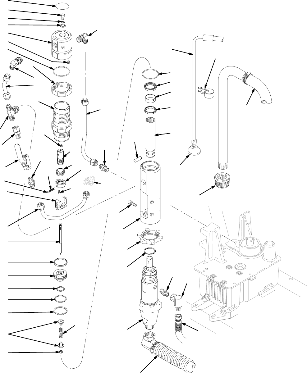
ti1428ati1428a
Parts Drawing -- GH200 Sprayers
89
114
110
33
50
28
78
95
21
77
16
57
12
53
66
32
127
84
14
18
71
11
15
83
74
76
42
29
31
61
103
122
67
111
120
86
92
72
73
64
50
65
93
36
94
60
8
82
20
41
123
63
114
16
Ref. 37
129
13
ti2266b
21310548
Parts List -- GH200 Sprayers
Ref.
No. Part No. Description Qty.
Ref.
No. Part No. Description Qty.
11 100139 PLUG, pipe 1
12† PLUG, pipe 1
13§ 104092 SCREW, cap, sch 2
14#* 105765 PACKING, o-ring 1
15† SCREW, cap, hex hd 1
16 117607 ELBOW, str thd 2
18* 108014 PACKING, o-ring 1
21 117608 NIPPLE, straight 1
28* 117739 WIPER, rod 1
29* 112342 BEARING, rod 1
31* 112561 PACKING, block 1
32 117441 VALVE, ball 1
33 189920 STRAINER, (1--11 1/2 npsm) 1
36 117609 TEE, branch, str thd 1
41 15B564 SCREW, cap, socket hd 4
42# 114231 NUT, lock, hex 1
50‡* 117283 PACKING, o-ring 2
53 117328 FITTING, nipple, straight 1
57† PACKING, o-ring 1
60# 15A690 ROD, trip 1
61# 15A693 ROD, hydraulic motor 1
63 243814 HOSE, coupled 1
64† 246180 CAP, hydraulic motor 1
65 15A726 NUT, jam 1
66‡ 15A727 SLEEVE, hydraulic cylinder 1
67 15A728 MANIFOLD, adapter 1
71† WASHER, sealing 1
72# 117645 SPRING, compression 1
73* 178207 BEARING, piston 1
74* 178226 SEAL, piston 1
76# 15B463 RETAINER, spring 2
77 189072 SLEEVE, valve 1
82† VALVE, spool 1
84# 192656 PISTON 1
86 193394 NUT, retaining 1
89 196723 CLIP, spring, Ultra Hi--boys 1
91 194317 LABEL, danger, st 1
92 197443 PIN, pump 1
93 198629 TUBE, hydraulic, supply 1
94 198630 TUBE, hydraulic, supply 1
95 198631 TUBE, hydraulic, return 1
103 246169 HOSE, drain 1
includes 110
110 241920 DEFLECTOR, threaded 1
111 246257 PUMP, displacement, 7900 1
Manual 309277
114 246168 TUBE, suction, 5 gal 1
includes 33
120 116551 RING, retaining 1
122 162485 NIPPLE, adapter 3
123 155494 UNION, swivel, 90°1
127 116813 FITTING, nipple, hydraulic 1
129† 15B063 LABEL 1
†Included in Cap Kit 246180
‡Included in Sleeve Kit 246176
§Included in Yoke Kit 246175
#Included in Trip Rod/Piston Kit 246255
*Included in Seal Kit 246174
YDANGER and WARNING labels are available at no charge.
31054822
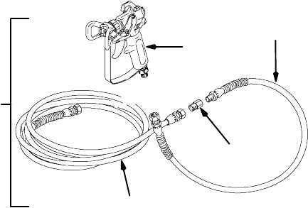
GH200 Sprayers with Spray Gun and Hoses
233941 Includes 201 and 202
Ref
No. Part No. Description Qty
201 233940 GH200 1
See cover and Parts, pages 16 -- 21
202 287037 KIT, gun, Contractor 1
3300 psi (227 bar, 22.7 MPa)
includes 202a -- 202d
202a 240797 HOSE, grounded, nylon; 3/8 in. ID; 1
cpld 3/8--18 npsm; 50 foot (15 m);
spring guards both ends
3300 psi (227 bar, 22.7 MPa)
202b 238358 HOSE, grounded, nylon; 3/16 in. ID; 1
cpld 1/4 npt(m) x 1/4 npsm(f);
3 foot (0.9 m); spring guards both ends
3300 psi (227 bar, 22.7 MPa)
202c 246220 Contractor Spray Gun 1
Includes 517 RACRXSwitchTipt
and HandTitetGuard
See 309639 for parts
202d 159841 ADAPTER, 3/8 X 1/4 in. npt 1
202c
200b
202a 0160
202d
202

23310548
Technical Data
Sprayer Hydraulic
Pressure psi
(bar)
Hydraulic
Reservoir
Capacity
Gallons
(Liters)
Motor HP
(kW)
Maximum
Delivery gpm
(lpm)
Maximum
Tip size
Fluid Inlet
in.
Fluid Outlet
in.
1 gun 2 guns npsm(m) npt(f)
GH200
Gas
1800 (124) 1.0 (3.8) 5.5 (4.1) 2.0 (7.6) 0.046 0.033 1
npsm(m)
3/8 3/8
GH200
Electric
1800 (124) 1.0 (3.8) 2.0 (1.5) 1.1 (4.2) 0.031 0.021 1
npsm(m)
3/8 3/8
BasicSprayerWettedParts: ............................
zinc and nickel-plated carbon steel, stainless steel,
PTFE, DelrinR,chrome plating, leather, V-Maxt
UHMWPE, aluminum, stainless steel, tungsten car-
bide, ceramic, nylon, aluminum
NOTE: DelrinRis a registered trademark of the DuPont Co.
Dimensions
Sprayer Weight lb (kg) Height in. (cm) Width in. (cm) Length in. (cm)
GH200 Gas 162 (73.6) 30 (76.2) 24 (61) 41 (104.1)
GH200 Electric 173 (78.6) 30 (76.2) 24 (61) 41 (104.1)
Sound Levels*:
Sound Pressure 96 dB(A)............................
Sound Power 110 dB(A)..............................
* Measured at maximum normal load conditions (Gas only)
Accessories
Must be purchased separately.
GRACO--APPROVED HYDRAULIC OIL
169236 5 Gallons (19 liters)
207428 1 Gallon (3.8 liters)

31054824
Graco Standard Warranty
Graco warrants all equipment manufactured by Graco and bearingits nameto befree fromdefects in material and workmanship on the
date of sale by an authorized Graco distributor to the original purchaser for use. With the exception of any special, extended, or limited
warranty published by Graco, Graco will, for a period of twelve months from the date of sale, repair or replace any part of the equipment
determined by Graco to be defective. This warranty applies only when the equipment is installed, operated and maintained in accor-
dance with Graco’s written recommendations.
This warranty does not cover, and Graco shall not be liable for general wear and tear, or any malfunction, damage or wear caused by
faulty installation, misapplication, abrasion, corrosion, inadequate or improper maintenance, negligence, accident, tampering, or sub-
stitution of non--Graco component parts. Nor shall Graco be liable for malfunction, damage or wear caused by the incompatibility of
Graco equipment with structures, accessories, equipment or materials not supplied by Graco, or the improper design, manufacture,
installation, operation or maintenance of structures, accessories, equipment or materials not supplied by Graco.
This warranty is conditioned upon the prepaid return of the equipment claimed to be defective to an authorized Graco distributor for
verification of the claimed defect. If the claimed defect is verified, Graco will repair or replace free of charge any defective parts. The
equipmentwill be returned to the original purchaser transportation prepaid. If inspection of the equipmentdoes notdisclose anydefect
in material or workmanship, repairs will be made at a reasonable charge, which charges may include the costs of parts, labor, and
transportation.
THIS WARRANTY IS EXCLUSIVE, AND IS IN LIEU OF ANY OTHER WARRANTIES, EXPRESS OR IMPLIED, INCLUDING BUT
NOT LIMITED TO WARRANTY OF MERCHANTABILITY OR WARRANTY OF FITNESS FOR A PARTICULAR PURPOSE.
Graco’s sole obligation and buyer’s sole remedy for any breach of warranty shall be as set forth above. The buyer agrees that no other
remedy (including, but not limited to, incidental or consequentialdamages for lost profits,lost sales, injury to person or property, or any
other incidental or consequential loss) shall be available. Any action for breach of warranty must be brought within two (2) years of the
date of sale.
Graco makes no warranty, and disclaims all implied warranties of merchantability and fitness for a particular purpose in connection
with accessories, equipment, materials or components sold but not manufactured by Graco. These items sold, but not manufactured
by Graco (such as electric motors, switches, hose, etc.), are subject to the warranty, if any, of their manufacturer. Graco will provide
purchaser with reasonable assistance in making any claim for breach of these warranties.
In no event will Graco be liable for indirect, incidental, special or consequential damages resulting from Graco supplying equipment
hereunder, or the furnishing, performance, or use of any products or other goods sold hereto, whether due to a breach of contract,
breach of warranty, the negligence of Graco, or otherwise.
FOR GRACO CANADA CUSTOMERS
The parties acknowledge that they have required that the present document, as well as all documents, notices and legal proceedings
entered into, given or instituted pursuant hereto or relating directly or indirectly hereto, be drawn up in English. Les parties reconnais-
sent avoir convenu que la rédaction du présente document sera en Anglais, ainsi que tous documents, avis et procédures judiciaires
exécutés, donnés ou intentés à la suite de ou en rapport, directement ou indirectement, avec les procedures concernées.
TO PLACE AN ORDER, contact your Graco distributor, or call this number to identify the distributor closest to you:
1--800--690--2894 Toll Free
All written and visual data contained in this document reflects the latest product information available at the time of publication.
Graco reserves the right to make changes at any time without notice.
Graco Headquarters: Minneapolis
International Offices: Belgium, China, Japan, Korea
GRACO INC. P.O. BOX 1441 MINNEAPOLIS, MN 55440--1441
www.graco.com
Printed in USA 310548F
8/2002 Rev. 06/2009
