Graco Inc 3A0149C Users Manual G15/G40 Spray Gun, Instructions/Parts, English
3A0149C Graco G15 G40 Manual 3A0149C
2015-02-09
: Graco-Inc Graco-Inc-3A0149C-Users-Manual-561366 graco-inc-3a0149c-users-manual-561366 graco-inc pdf
Open the PDF directly: View PDF ![]() .
.
Page Count: 40
Instructions - Parts List
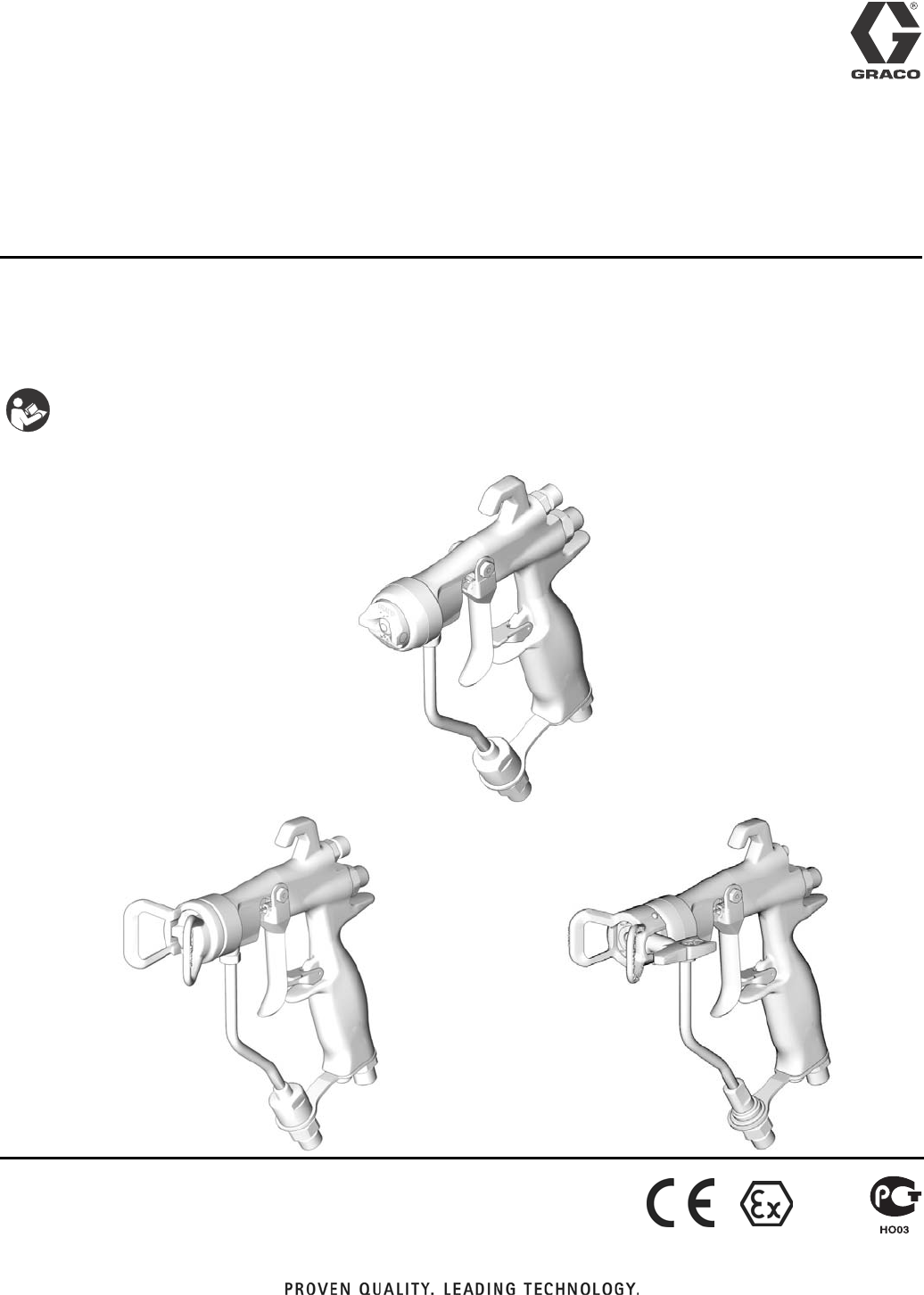
G15/G40 Spray Gun 3A0149C
ENG
A lightweight line of air-assisted spray guns for spraying and finishing a variety of paints
and coatings, particularly in applications requiring uniform atomization and high transfer
efficiency. For professional use only.
Important Safety Instructions:
Read all warnings and instructions in this manual. Save these
instructions. See page 2 for model information including maxi-
mum working pressure.
Model G15 TI6553A
Model G40
TI6844A TI7204B
Model G40 w/RAC tip
II 2 G

Models
23A0149C
Contents
Models . . . . . . . . . . . . . . . . . . . . . . . . . . . . . . . . . . . 2
Related Manuals . . . . . . . . . . . . . . . . . . . . . . . . . . . 3
Warnings . . . . . . . . . . . . . . . . . . . . . . . . . . . . . . . . . 4
Installation . . . . . . . . . . . . . . . . . . . . . . . . . . . . . . . . 6
Typical Installation . . . . . . . . . . . . . . . . . . . . . . . . 6
Ventilate the Spray Booth . . . . . . . . . . . . . . . . . . 6
Grounding . . . . . . . . . . . . . . . . . . . . . . . . . . . . . . 6
Air Line . . . . . . . . . . . . . . . . . . . . . . . . . . . . . . . . 7
Fluid Line . . . . . . . . . . . . . . . . . . . . . . . . . . . . . . 7
Setup . . . . . . . . . . . . . . . . . . . . . . . . . . . . . . . . . . . . . 8
Flush Before Using Equipment . . . . . . . . . . . . . . 8
Select a Spray Tip and Air Cap . . . . . . . . . . . . . . 8
Install a Spray Tip . . . . . . . . . . . . . . . . . . . . . . . . 8
Position the Air Cap . . . . . . . . . . . . . . . . . . . . . . 8
Air Cap Alignment Pin . . . . . . . . . . . . . . . . . . . . . 8
Reverse-A-Clean® (RAC) Tip . . . . . . . . . . . . . . . 9
Operation . . . . . . . . . . . . . . . . . . . . . . . . . . . . . . . . 10
Pressure Relief Procedure . . . . . . . . . . . . . . . . 10
Trigger Lock . . . . . . . . . . . . . . . . . . . . . . . . . . . . 10
How the Air-Assisted Spray Gun Operates . . . . 11
Spray Pattern Adjustment . . . . . . . . . . . . . . . . . 11
HVLP Operation . . . . . . . . . . . . . . . . . . . . . . . . 12
Fluid Application . . . . . . . . . . . . . . . . . . . . . . . . 12
Daily Gun Care, Flushing, and Cleaning . . . . . . . 13
General System Maintenance . . . . . . . . . . . . . . 14
Fluid Filter Maintenance . . . . . . . . . . . . . . . . . . 14
Flushing and Cleaning . . . . . . . . . . . . . . . . . . . . 14
Reverse-A-Clean® (RAC) Tip . . . . . . . . . . . . . . 16
Troubleshooting . . . . . . . . . . . . . . . . . . . . . . . . . . . 18
Repair . . . . . . . . . . . . . . . . . . . . . . . . . . . . . . . . . . . 20
Repair Kits . . . . . . . . . . . . . . . . . . . . . . . . . . . . . 20
Fan Valve Replacement . . . . . . . . . . . . . . . . . . . 20
Complete Gun Packing Repair . . . . . . . . . . . . . 20
Parts . . . . . . . . . . . . . . . . . . . . . . . . . . . . . . . . . . . . 26
Spray Tip Selection Chart . . . . . . . . . . . . . . . . . . . 32
Spray Tips, for use with G15/G40 Air Cap . . . . . 32
RAC SwitchTips, for use with
G40 RAC Air Cap . . . . . . . . . . . . . . . . . . . . 33
RAC SwitchTips, for use with
G40 RAC Air Cap, Continued . . . . . . . . . . . 34
Accessories . . . . . . . . . . . . . . . . . . . . . . . . . . . . . . 35
Part Interchangeability Guide . . . . . . . . . . . . . . 37
Dimensions . . . . . . . . . . . . . . . . . . . . . . . . . . . . . . . 38
Technical Data . . . . . . . . . . . . . . . . . . . . . . . . . . . . 39
Graco Standard Warranty . . . . . . . . . . . . . . . . . . . 40
Graco Information . . . . . . . . . . . . . . . . . . . . . . . . . 40
Models
Part Series
Maximum Working
Air Pressure
psi (MPa, bar)
Maximum Working
Fluid Pressure
psi (MPa, bar) Description Includes:
24C853 A 100 (0.7, 7.0) 1500 (10.5, 105)
G15 Medium Pressure
Air-Assisted Spray Gun,
Carbide Seat and Ball
24C866
Air Cap
with pin
24C854 A 100 (0.7, 7.0) 1500 (10.5, 105)
G15 Medium Pressure
Air-Assisted Spray Gun,
Plastic Seat, SST Ball
24C855 A 100 (0.7, 7.0) 4000 (28, 280)
G40 High Pressure Air-Assisted
Spray Gun, Carbide Seat and Ball 249180
Air Cap
without
pin
24C856 A 100 (0.7, 7.0) 4000 (28, 280)
G40 High Pressure, High Flow
Air-Assisted Spray Gun,
Carbide Seat and Ball
24C857 A 100 (0.7, 7.0) 4000 (28, 280)
G40 High Pressure Air-Assisted
Spray Gun, Carbide Seat and
Ball, Reverse-A-Clean® (RAC) Tip
24C921
RAC
Air Cap

Related Manuals
3A0149C 3
Related Manuals
This manual is available in the following languages:
Manual Language
3A0149A English
3A0283A French
3A0282A Spanish
3A0442 Chinese
3A0443 Japanese
3A0444 Korean
Warnings
43A0149C
Warnings
The following are general warnings related to the setup, use, grounding, maintenance, and repair of this equipment.
Additional, more specific warnings may be found throughout the body of this manual where applicable. Symbols that
appear in the body of the manual refer to these general warnings. When these symbols appear throughout the man-
ual, refer back to these pages for a description of the specific hazard.
WARNING
FIRE AND EXPLOSION HAZARD
Flammable fumes, such as solvent and paint fumes, in work area can ignite or explode. To help prevent
fire and explosion:
• Use equipment only in well ventilated area.
• Eliminate all ignition sources; such as pilot lights, cigarettes, portable electric lamps, and plastic drop
cloths (potential static arc).
• Keep work area free of debris, including solvent, rags and gasoline.
• Do not plug or unplug power cords, or turn power or light switches on or off when flammable fumes
are present.
• Ground all equipment in the work area. See Grounding instructions.
• Use only grounded hoses.
• Hold gun firmly to side of grounded pail when triggering into pail.
• If there is static sparking or you feel a shock, stop operation immediately. Do not use equipment
until you identify and correct the problem.
• Keep a working fire extinguisher in the work area.
SKIN INJECTION HAZARD
High-pressure fluid from gun, hose leaks, or ruptured components will pierce skin. This may look like just
a cut, but it is a serious injury that can result in amputation. Get immediate surgical treatment.
• Do not spray without tip guard and trigger guard installed.
• Engage trigger lock when not spraying.
• Do not point gun at anyone or at any part of the body.
• Do not put your hand over the spray tip.
• Do not stop or deflect leaks with your hand, body, glove, or rag.
• Follow the Pressure Relief Procedure when you stop spraying and before cleaning, checking, or
servicing equipment.
• Tighten all fluid connections before operating the equipment.
• Check hoses and couplings daily. Replace worn or damaged parts immediately.

Warnings
3A0149C 5
EQUIPMENT MISUSE HAZARD
Misuse can cause death or serious injury.
• Do not operate the unit when fatigued or under the influence of drugs or alcohol.
• Do not exceed the maximum working pressure or temperature rating of the lowest rated system
component. See Technical Data in all equipment manuals.
• Use fluids and solvents that are compatible with equipment wetted parts. See Technical Data in all
equipment manuals. Read fluid and solvent manufacturer’s warnings. For complete information
about your material, request MSDS from distributor or retailer.
• Do not leave the work area while equipment is energized or under pressure. Turn off all equipment
and follow the Pressure Relief Procedure when equipment is not in use.
• Check equipment daily. Repair or replace worn or damaged parts immediately with genuine manu-
facturer’s replacement parts only.
• Do not alter or modify equipment.
• Use equipment only for its intended purpose. Call your distributor for information.
• Route hoses and cables away from traffic areas, sharp edges, moving parts, and hot surfaces.
• Do not kink or over bend hoses or use hoses to pull equipment.
• Keep children and animals away from work area.
• Comply with all applicable safety regulations.
TOXIC FLUID OR FUMES HAZARD
Toxic fluids or fumes can cause serious injury or death if splashed in the eyes or on skin, inhaled, or
swallowed.
• Read MSDS’s to know the specific hazards of the fluids you are using.
• Store hazardous fluid in approved containers, and dispose of it according to applicable guidelines.
PERSONAL PROTECTIVE EQUIPMENT
You must wear appropriate protective equipment when operating, servicing, or when in the operating
area of the equipment to help protect you from serious injury, including eye injury, hearing loss, inhala-
tion of toxic fumes, and burns. This equipment includes but is not limited to:
• Protective eyewear, and hearing protection.
• Respirators, protective clothing, and gloves as recommended by the fluid and solvent manufacturer
WARNING
Installation
63A0149C
Installation
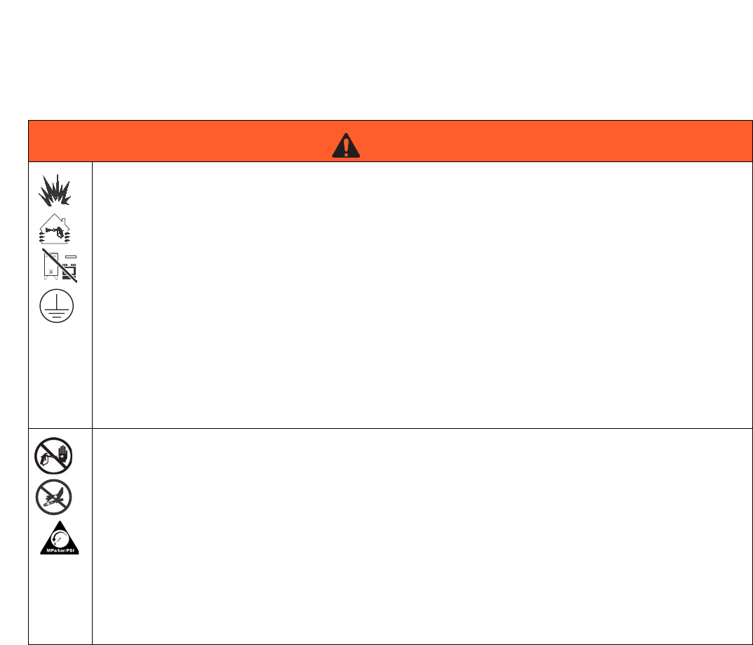
Typical Installation
NOTE: The typical installation shown in FIG. 1 is only a
guide for selecting and installing air-assisted spray sys-
tems. Contact your Graco distributor for assistance in
designing a system to meet your needs.
Ventilate the Spray Booth
Grounding
Key:
A Air Line Filter
B Air Shutoff Valve
C Gun Air Pressure Regulator
DAir Line
ESpray Gun
F Electrically Conductive Fluid Hose
G Gun Air Supply Hose
• To prevent hazardous concentrations of toxic
and/or flammable vapors, spray only in a properly
ventilated spray booth. Do not operate the spray
gun unless ventilation fans are operating.
• Check and follow all of the National, State, and
Local codes regarding air exhaust velocity
requirements.
• Check and follow all local safety and fire codes.
• Check your local electrical code and pump man-
ual for detailed grounding instructions. Use only
electrically conductive fluid hoses.
• Ground the spray gun through connection to a
properly grounded fluid supply hose and pump.
FIG. 1: Typical Installation (Model G15 Shown)
TI6554A
A
B
C
E
F
G
D
Installation
3A0149C 7
Air Line
1. Install an air filter (A) on the gun air line to ensure a
dry, clean air supply to the gun. Dirt and moisture
can ruin the appearance of your finished workpiece.
See FIG. 1.
2. Install an air pressure regulator (C) on the gun air
line to control air pressure to the gun.
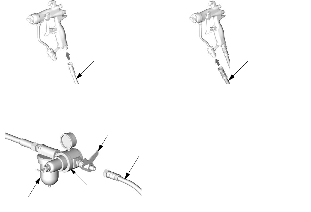
3. Install an air shutoff valve (B) on the gun air line and
on the pump air line, to shut off air to the gun.
4. Use a 3/16 in. (5 mm) I.D. or larger air hose to mini-
mize excessive pressure drop in the hose.
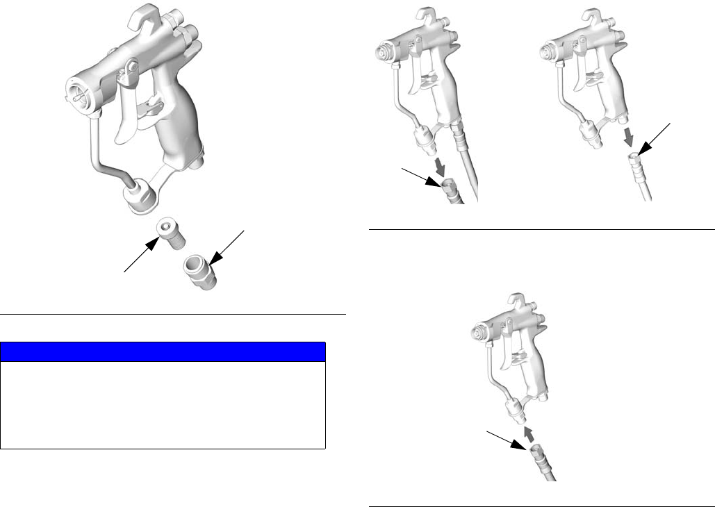
NOTE: The gun air inlet has a 1/4-18 npsm (R1/4-19)
compound male thread that is compatible with NPSM
and BSP female swivel connectors.
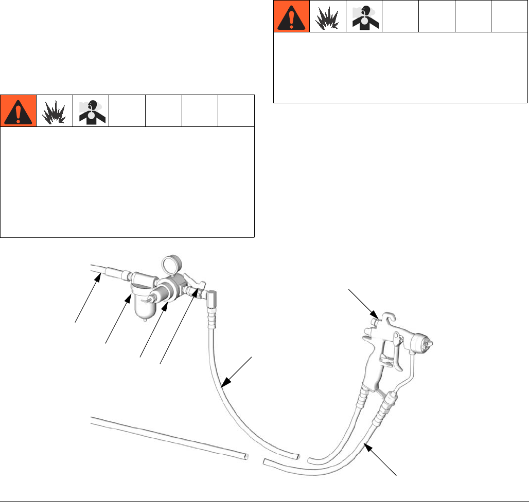
5. Connect the air hose (G) to the 1/4 npsm gun air
inlet. See FIG. 2.
6. Connect the other end of the air hose (G) to the out-
let of the air shutoff valve. See FIG. 3.
Fluid Line
• Before connecting the fluid line, blow it out with air
and flush it with solvent. See Flushing and Clean-
ing, page 14. Use solvent which is compatible with
the fluid to be sprayed.
• If better control of fluid pressure is needed, install a
fluid regulator on the fluid line to better control fluid
pressure to the gun.
1. Use a fluid filter to remove coarse particles and sed-
iment, to avoid clogging the spray tip and causing
finishing defects.
NOTE: Guns are equipped with a built-in 100 mesh fluid
filter to provide final filtering just before spraying.
2. Connect the fluid hose (F) to the gun fluid inlet. See
FIG. 4. If desired, install a fluid swivel connector
(189018) at the gun inlet for best maneuverability.
See Accessories, page 35.
3. Connect the other end of the fluid hose (F) to the
pump fluid outlet.
FIG. 2
FIG. 3
TI6556A
G
TI4838A
C
G
B
A
FIG. 4
TI6846A
F
Setup
83A0149C
Setup
Flush Before Using Equipment
1. The equipment was tested with lightweight oil, which
is left in the fluid passages to protect parts. To avoid
contaminating your fluid with oil, flush the equipment
with a compatible solvent before using the equip-
ment. See Flushing and Cleaning, page 14.
2. Relieve the pressure. See Pressure Relief Proce-
dure, page 10.
Select a Spray Tip
The fluid flow and pattern width depend on the size of
the spray tip, the fluid viscosity, and the fluid pressure.
See Spray Tip Selection Chart, page 32. Contact your
Graco distributor for assistance in selecting an appropri-
ate spray tip for your application.
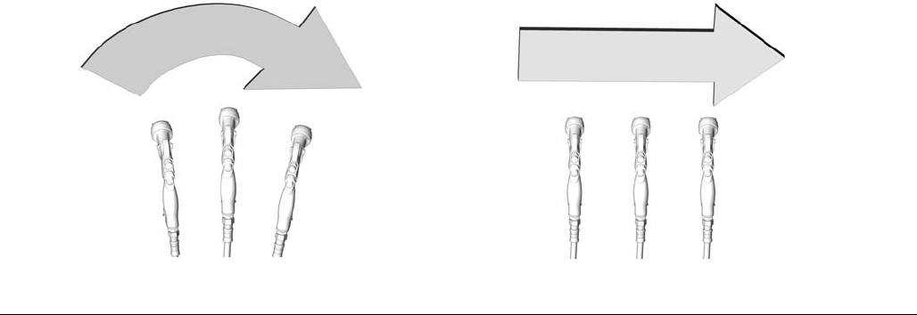
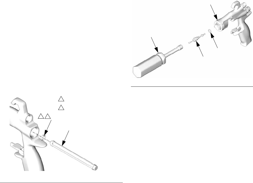
Air Cap Alignment Pin
Model G15 guns use an air cap alignment pin to position
the air cap. The standard location of the air cap align-
ment pin is the horizontal air cap position.
If you would like to change the spray pattern direction,
use a needle nose pliers to unscrew the pin and relocate
it to the desired position. See FIG. 5. When relocating
the pin use low-strength thread locker. Torque to 1.5-2.5
in-lb (0.2-0.3 N•m). DO NOT OVERTIGHTEN.
The air cap alignment pin can be removed according to
preference. Air cap alignment pins will not work with
model G40 guns.
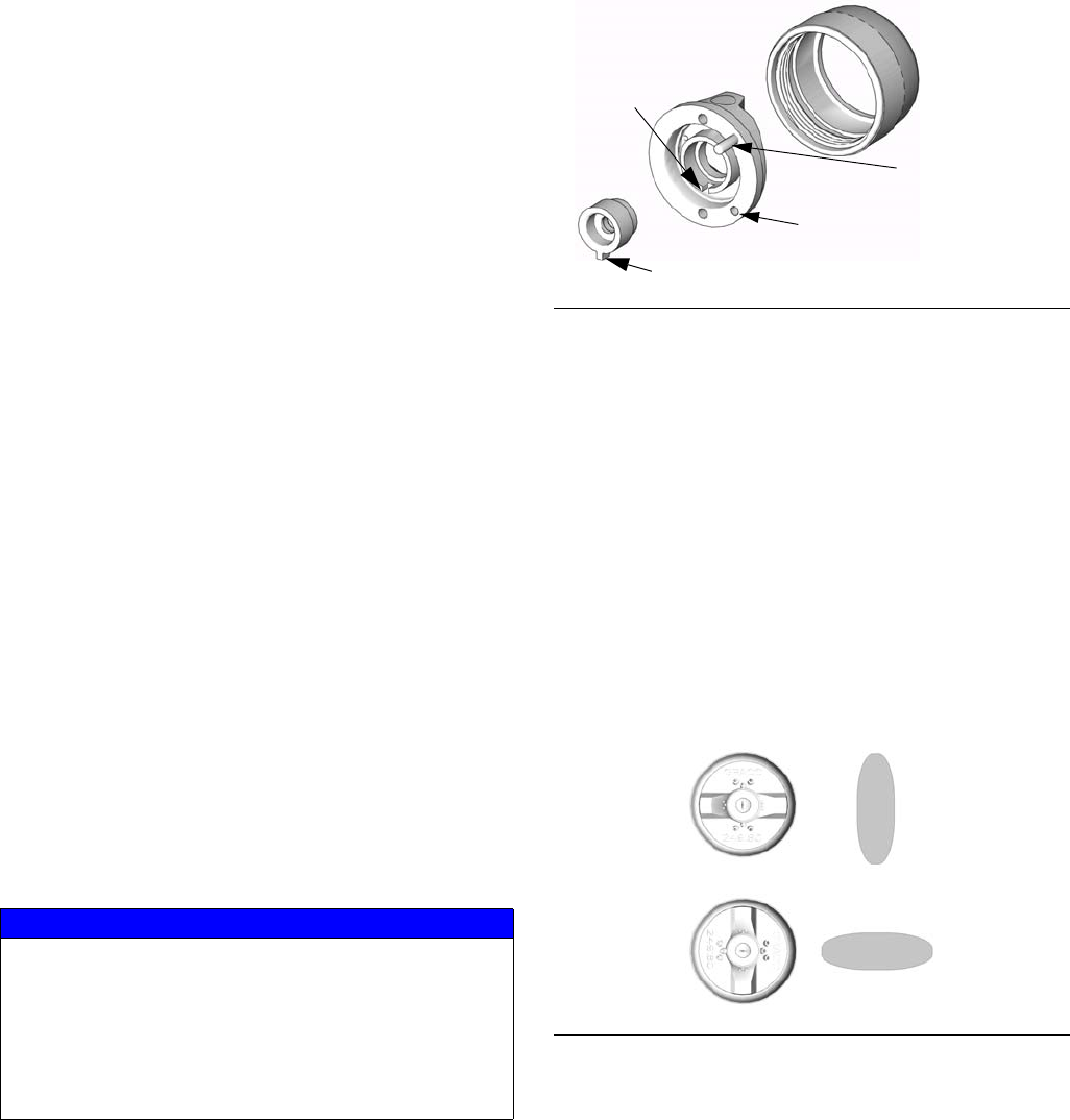
Install a Spray Tip
Install a spray tip in the air cap. Ensure that the tip locat-
ing tab is positioned in the slot of the air cap. See FIG. 5.
Position the Air Cap
Assemble the air cap to the gun. The air cap and spray
tip position determine the direction of the spray pattern.
Rotate the air cap (the spray tip rotates with it) as
needed to achieve the desired spray pattern direction.
See FIG. 6. For the G15 air cap, the alignment pin will
stop the rotation in the proper orientation.
Tighten the air cap retaining ring (6) firmly by hand to
ensure a good seal between the tip gasket and the dif-
fuser (5).
NOTICE
The alignment pin and retaining ring for current model
guns are different from the earlier model guns. They
are not interchangeable. Use of the incorrect pin will
result in fluid leakage or loss of the alignment feature.
Use of the wrong retaining ring will damage retaining
ring and gun threads. See Part Interchangeability
Guide, page 37.
FIG. 5
FIG. 6
TI6847A
Slot
Tip locating tab
Horizontal air
cap position
(standard)
Vertical air
cap position
TI6558A
Setup
3A0149C 9
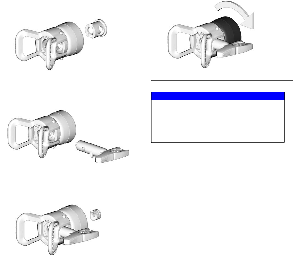
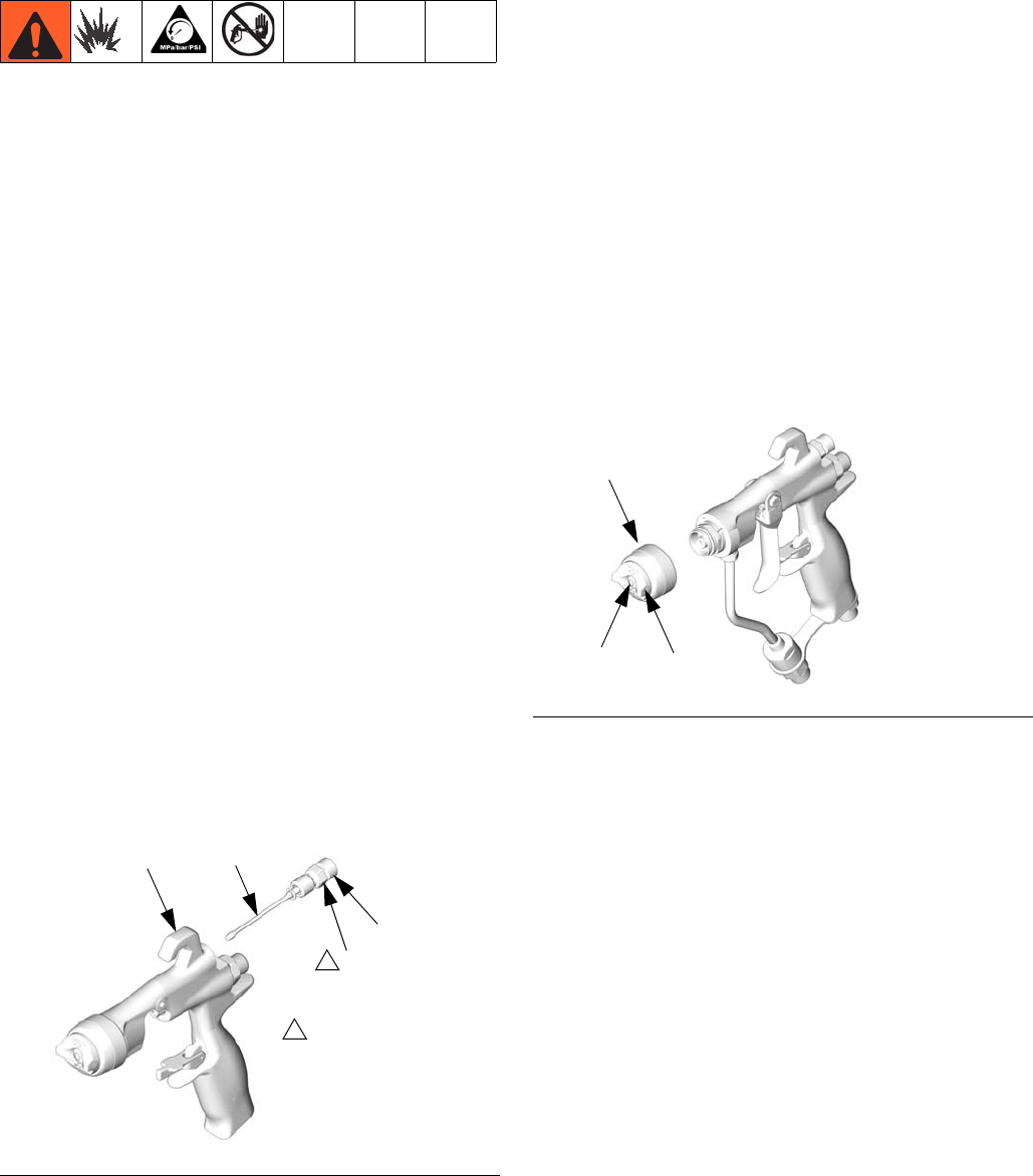
Reverse-A-Clean® (RAC) Tip Assembly
Model 24C857 guns use a Reverse-A-Clean® (RAC) tip.
To assemble the RAC tip, insert the seat housing into
the air cap assembly.
Insert the SwitchTip.
Insert the gasket seat.
Screw the RAC tip assembly onto the gun and tighten
firmly by hand.
FIG. 7
FIG. 8
FIG. 9
TI7196A
TI7197A
TI7198A
FIG. 10
NOTICE
The RAC assembly for current model guns uses a
different seat housing and has a coarser thread
than the RAC assembly for earlier model guns.
They are not interchangeable. Use of the incor-
rect RAC assembly will damage the threads. See
Part Interchangeability Guide, page 37.
TI7199A
Operation
10 3A0149C
Operation
Be sure to read and follow the Warnings on pages 4
and 5 and throughout the text of this instruction manual.
Keep the wallet sized warning card (222385), provided
with the gun, with the operator of this equipment at all
times. The card contains important treatment informa-
tion should a skin injection injury occur. Additional cards
are available at no charge from Graco.
Pressure Relief Procedure
To reduce the risk of an injury from injection, splashing
fluid, or moving parts, follow the Pressure Relief Proce-
dure whenever you:
• are instructed to relieve the pressure,
• stop spraying,
• check or service any of the system equipment,
or install or clean the spray tip.
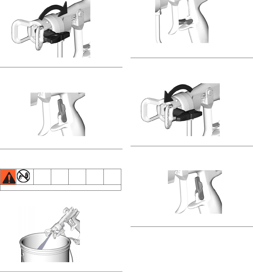
1. Engage the trigger lock. See FIG. 12.
2. Shut off the pump. See your pump manual.
3. Shut off the gun air supply.
4. Disengage the trigger lock. See FIG. 12.
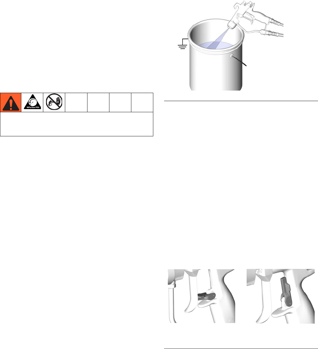
5. Hold a metal part of the gun firmly to a grounded
metal pail. Trigger the gun to relieve pressure. See
FIG. 11.
6. Open all fluid drain valves in the system, having a
waste container ready to catch drainage. Leave
drain valve(s) open until you are ready to spray
again.
7. Engage the trigger lock. See FIG. 12.
8. If you suspect the spray tip or hose is clogged or
that pressure has not been fully relieved after follow-
ing the steps above, VERY SLOWLY loosen the tip
guard retaining ring or hose end coupling to relieve
pressure gradually, then loosen completely. Clear
hose or tip obstruction.
Trigger Lock
Always engage the trigger lock when you stop spraying
to prevent the gun from being triggered accidentally by
hand or if dropped or bumped.
Trapped air can cause the pump to cycle unexpect-
edly, which could result in serious injury from splash-
ing or moving parts.
FIG. 11
FIG. 12
TI6555A
TI6581A TI6582A
ENGAGED DISENGAGED
Operation
3A0149C 11
How the Air-Assisted Spray Gun
Operates
The air-assisted spray gun combines airless and air
spraying concepts. The spray tip shapes the fluid into a
fan pattern, as does a conventional airless spray tip. Air
from the air cap further atomizes the fluid and completes
the atomization of the paint tails into the pattern to pro-
duce a more uniform pattern. The width of the pattern
can be adjusted by the pattern adjustment valve.
The air-assisted spray gun differs from an air spray gun
in that increasing the pattern air reduces the pattern
width. To increase the pattern width, use less pattern air
or a larger size tip.
The spray gun has a built-in lead and lag operation.
When triggered, the gun begins emitting air before the
fluid is discharged. When the trigger is released, the
fluid stops before the air flow stops. This helps assure
the spray is atomized and prevents fluid buildup on the
air cap.
Spray Pattern Adjustment
1. Do not turn on the gun air supply yet. Set the fluid
pressure at a low starting pressure. If a fluid pres-
sure regulator is installed, use it to make adjust-
ments.
If your system does not have a fluid regulator, the
fluid pressure is controlled by the air regulator sup-
plying the pump, per the formula below:
2. Trigger the gun to check the atomization; do not be
concerned about the pattern shape yet.
3. Slowly increase the fluid pressure, just to the point
where a further increase in fluid pressure does not
significantly improve fluid atomization.
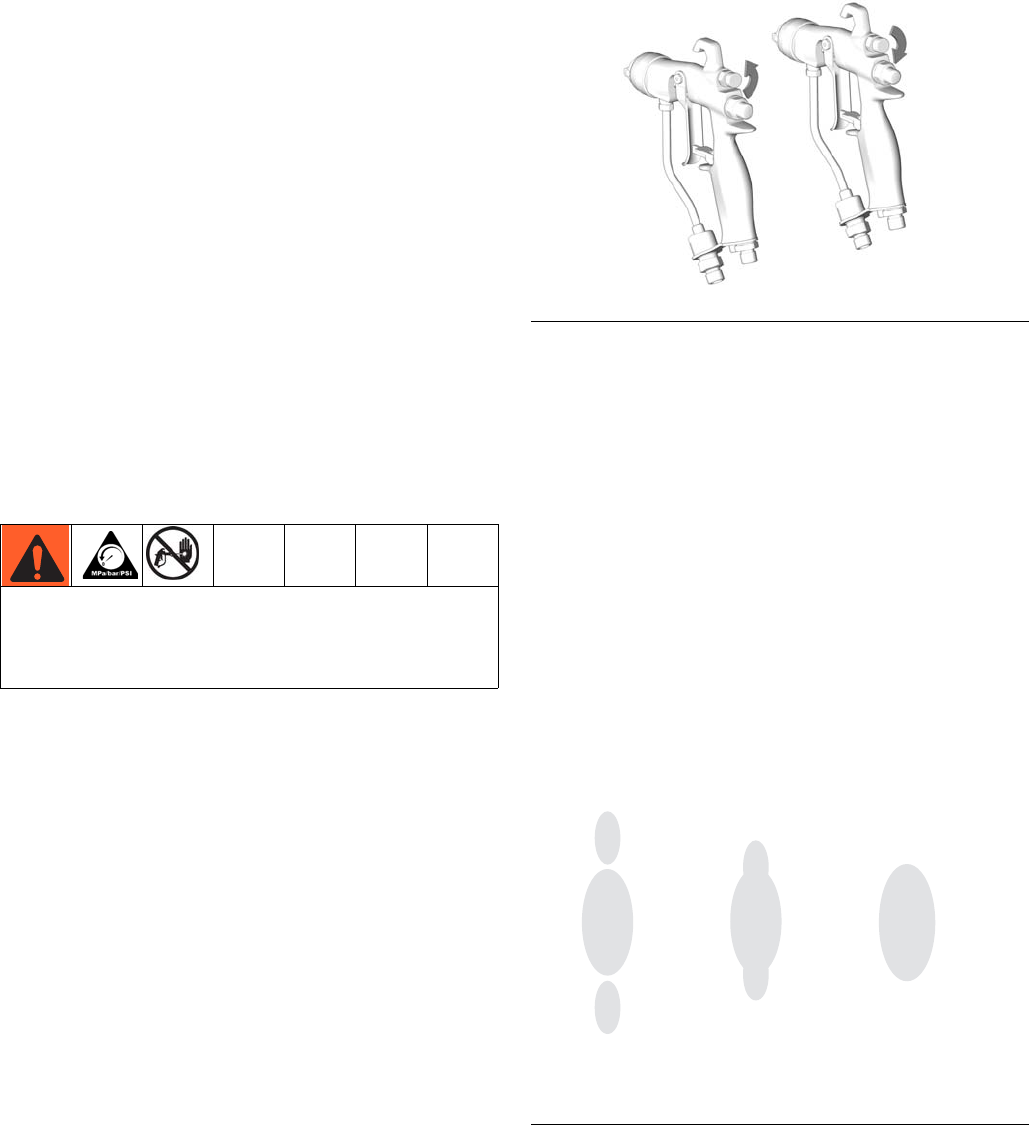
4. Close off the pattern adjustment air by turning the
knob clockwise (in) all the way. See FIG. 13. This
sets the gun for its widest pattern.
5. Set the atomizing air pressure at about 5 psi
(3.5 kPa, 0.35 bar) when triggered. Check the spray
pattern, then slowly increase the air pressure until
the tails are completely atomized and pulled into the
spray pattern. See FIG. 14. Seven to 10 psi (4.9 to
7.0 kPa, 0.49 to 0.7 bar) air pressure is typically
enough to atomize the tails, especially for low vis-
cosity materials. Setting the air pressure too high
will cause material to build up on the air cap and
decrease transfer efficiency. Do not exceed 100 psi
(0.7 MPa, 7 bar) air pressure to the gun.
For a narrower pattern, turn the pattern adjustment
valve knob counterclockwise (out). See FIG. 13. If
the pattern is still not narrow enough, increase the
air pressure to the gun slightly or use a different size
tip. (Not available for RAC tip guns.)
To reduce the risk of component rupture and serious
injury, including injection, do not exceed the gun’s maxi-
mum fluid working pressure or the maximum working
pressure of the lowest rated component in the system.
Pump
Ratio
x Pump Air Regulator
Setting
=Fluid
Pressure
FIG. 13
FIG. 14
TI6559A
OPEN
CLOSE
no air too little air correct amount
of air
TI0792A
Operation
12 3A0149C
HVLP Operation
NOTE: For HVLP operation, the atomization air must not
exceed 10 psi. Use HVLP Verification Kit 24C788 to ver-
ify air psi.
NOTE: There is no fan adjustment when using RAC tips
and caps.
Fluid Application
Always hold the gun at a right angle from the surface.
Do not make an arc with the gun as it causes an uneven
coat of fluid. See FIG. 15.
1. To achieve the best results when applying fluid,
keep the gun perpendicular to the surface and main-
tain a consistent distance of approximately 8 to 12
in. (200 to 300 mm) from the object being sprayed.
2. To obtain an even finish, use smooth, even strokes
across the object being sprayed with 50% overlap.
3. Paint using parallel strokes. This spray gun applies
all coatings evenly without cross coating.
FIG. 15
TI6561A TI6562A
INCORRECT CORRECT
Daily Gun Care, Flushing, and Cleaning
3A0149C 13
Daily Gun Care, Flushing, and Cleaning
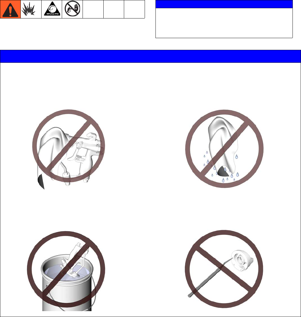
NOTICE
Methylene chloride with formic or propionic acid is
not recommended as a flushing or cleaning solvent
with this gun as it will damage aluminum and nylon
components.
NOTICE
Do not use any cleaning method which may allow solvent into the gun air passages. Solvent left in gun air pas-
sages could result in a poor quality paint finish.
Do not point the gun up while cleaning it.
Do not immerse the gun in solvent.
Do not wipe the gun with a cloth soaked in solvent;
wring out the excess.
Do not use metal tools to clean the air cap holes
as this may scratch them; scratches can distort
the spray pattern.
TI6563A
TI6564A
TI4827A
TI6565A
Daily Gun Care, Flushing, and Cleaning
14 3A0149C
General System Maintenance
1. Relieve the pressure, page 10.
2. Clean the fluid and air line filters daily.
3. Check for any fluid leakage from the gun and fluid
hoses. Tighten fittings or replace equipment as
needed.
4. Flush the gun before changing colors and whenever
you are done operating the gun.
Fluid Filter Maintenance
1. Unscrew the fluid inlet fitting (18).
2. Remove and inspect the inline fluid filter (12). Clean
or replace the filter as necessary.
Flushing and Cleaning
NOTE:
• Flush before changing colors, before fluid can dry in
the equipment, at the end of the day, before storing,
and before repairing equipment.
• Flush at the lowest pressure possible. Check con-
nectors for leaks and tighten as necessary.
• Flush with a fluid that is compatible with the fluid
being dispensed and the equipment wetted parts.
1. Relieve the pressure, page 10.
2. Remove the air cap retaining ring (6), air cap (21),
and spray tip (33). Soak the spray tip in a compati-
ble solvent.
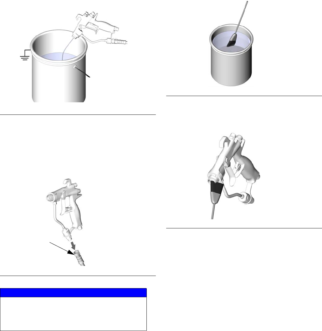
3. Disconnect the fluid supply hose (F) and air supply
hose (G) from the gun.
4. Connect the solvent supply hose (T) to the gun.
FIG. 16
NOTICE
The threads on the fluid inlet fitting for new model
guns are slightly finer than the threads on the old
model guns. The fluid inlet fittings are not inter-
changeable. Use of an incorrect fitting will dam-
age the threads.
TI6735A
12
18 FIG. 17
FIG. 18
TI6566A TI6567A
F
G
T
TI6566A
Daily Gun Care, Flushing, and Cleaning
3A0149C 15
5. Increase the pressure slowly. Point the gun down
into a grounded metal container, and flush the gun
with solvent until all traces of fluid are removed from
the gun passages.
6. Turn off the solvent supply.
7. Relieve the pressure.
8. Disconnect the solvent supply hose (T) from the
gun.
9. If it is necessary to remove the diffuser (5) to clean,
trigger the gun while you remove the diffuser with
the gun tool (30).
10. Dip the end of a soft-bristle brush into a compatible
solvent. Do not continuously soak the brush's bris-
tles with solvent and do not use a wire brush.
11. With the gun pointed down, clean the front of the
gun, using the soft-bristle brush and solvent.
12. Scrub the air cap retaining ring (6), air cap (21), dif-
fuser (5), and spray tip (33) with the soft-bristle
brush. To clean out air cap holes, use a soft tool,
such as a toothpick, to avoid damaging critical sur-
faces. Blow air through the spray tip to ensure the
orifice is clean. Clean the air cap and spray tip daily,
minimum. Some applications require more frequent
cleaning.
FIG. 19
FIG. 20
NOTICE
Trigger the gun whenever you tighten or remove the
diffuser (5). This keeps the needle ball away from
the seating surface and prevents the seat from
being damaged.
TI6729A
TI6730A
T
FIG. 21
FIG. 22
TI4845A
TI6569A
Daily Gun Care, Flushing, and Cleaning
16 3A0149C
13. If the diffuser was removed, trigger the gun while
you reinstall the diffuser (5) with the gun tool (30).
Tighten the diffuser securely to obtain a good seal.
Torque to 155-165 in-lb (18-19 N•m). When properly
tightened, the flange will bottom out on the gun.
14. Install the air cap retaining ring (6), air cap (21), and
spray tip (33).
15. Dampen a soft cloth with solvent and wring-out the
excess. Point the gun down and wipe off the outside
of the gun.
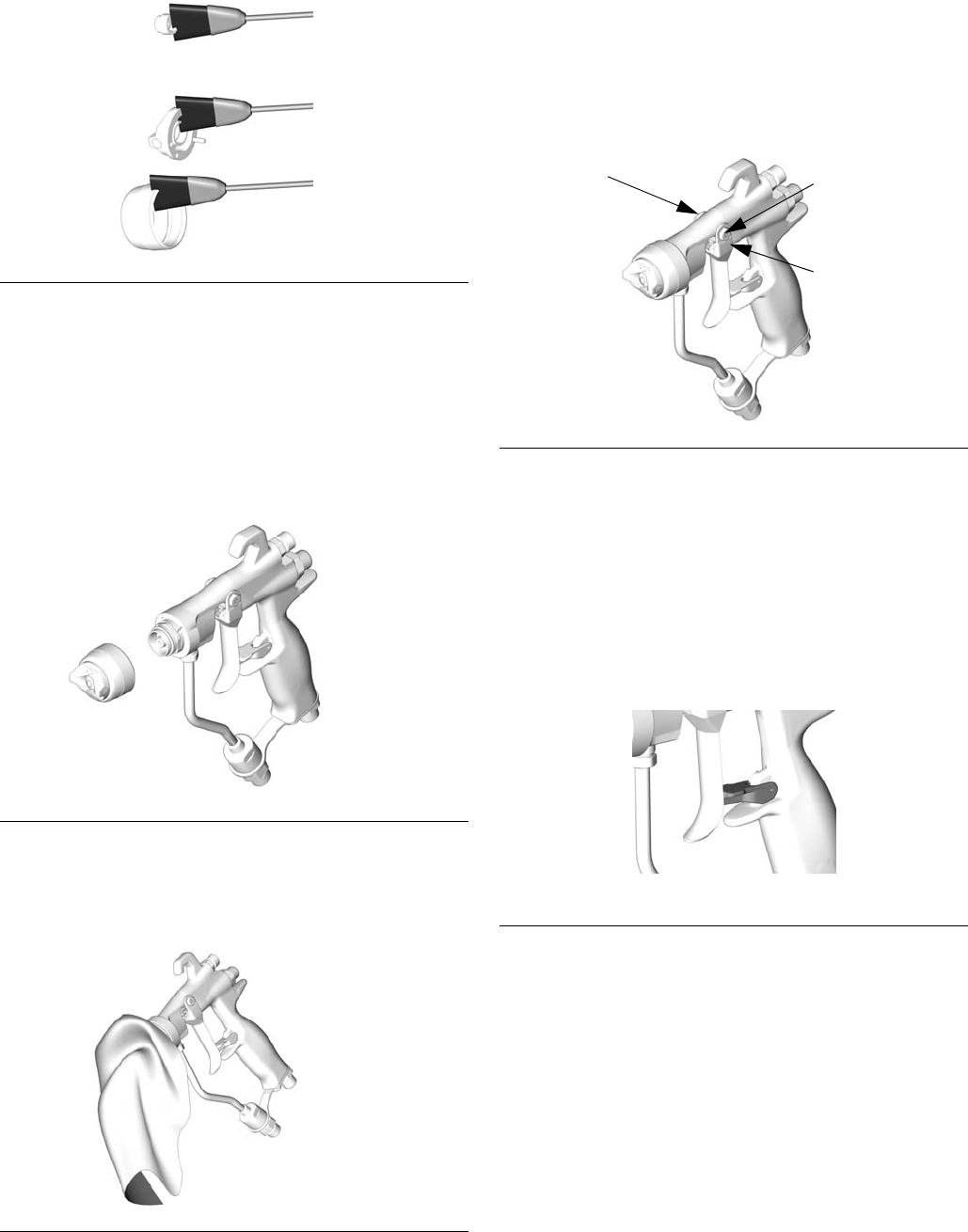
16. After cleaning the gun, lubricate the following parts
with lubricant 111265 weekly:
• Trigger pivot pin (A)
• Boss on both sides of the gun where the trigger
contacts the gun body (B)
• Fluid needle shaft, behind trigger (C)
Reverse-A-Clean® (RAC) Tip
NOTE: Do not soak the RAC tip seat gasket (33a) in sol-
vent for extended periods of time or swelling may occur.
Clearing a clogged RAC tip
Release the trigger and engage the trigger lock.
FIG. 23
FIG. 24
FIG. 25
TI6570A
TI6568A
TI6571A
FIG. 26
FIG. 27
TI6553A
B
C
A
ENGAGED
TI6581A
Daily Gun Care, Flushing, and Cleaning
3A0149C 17
Rotate the SwitchTip.
Disengage the trigger lock.
Trigger the gun into a pail to clear the clog.
Engage the trigger lock.
Return the SwitchTip to its original position.
Disengage the trigger lock and continue spraying.
FIG. 28
FIG. 29
Do not point gun at anyone or at any part of the body.
FIG. 30
TI7200A
DISENGAGED TI6580A
TI7202A
FIG. 31
FIG. 32
FIG. 33
TI6581A
ENGAGED
TI7201A
TI6582A
DISENGAGED
Troubleshooting
18 3A0149C
Troubleshooting
NOTE:
• Check all possible remedies in the troubleshooting
charts before disassembling the gun.
• Some improper patterns are caused by the
improper balance between air and fluid.
Problem Cause Solution
Fluid leakage from back of fluid
packing area.
Worn packings or needle shaft. Replace needle assembly (2).
Air leakage from gun. Air valve not seating properly. Clean or replace air valve (8).
Fluid leakage from front of gun. Needle ball worn or damaged. Replace needle assembly (2) and seat (5c).
Worn seat assembly. Replace the seat (5c) and gasket (5b, carbide
models only). The gasket must be replaced
whenever the seat assembly is removed.
Do not reverse the direction of the plastic seat
(5c, model 24C854 gun only) if it is worn. The
seat must be replaced it if is worn.
Fluid viscosity too low for proper
seal with carbide seat.
Install plastic seat (5c).
Fluid in air passages. Spray tip seal leaking. Tighten retaining ring (6) or replace spray tip
(33).
Leaking around seat housing. Replace the gasket (5b, carbide models only).
The gasket must be replaced whenever the
seat assembly is removed.
Fluid inlet fitting leaking. Replace the fluid tube gasket (22). The gas-
ket must be replaced whenever the fluid tube
connector is removed.
Slow fluid shut-off. Fluid buildup on fluid needle
components.
Remove and clean or replace the fluid needle
assembly (2).
No fluid output when triggered. Spray tip plugged. Clean spray tip. See page 14.
Fluid filter or fluid hose plugged. After tip removal (see above), very slowly
loosen the hose end coupling at the gun and
relieve pressure gradually. Then loosen com-
pletely to clear the obstruction. Clean or
replace filter (12).

Troubleshooting
3A0149C 19
Fluttering or spitting spray. Insufficient fluid supply. Adjust fluid regulator or fill fluid supply tank.
Air in paint supply line. Check, tighten pump siphon hose connec-
tions, bleed air from paint line.
Attempting to “feather” (partially
trigger the gun).
Cannot “feather” with an AA gun. Feather will
cause drastic reduction of pressure at the tip,
resulting in poor atomization and/or spitting.
Striping spray. Spray tip partially plugged. Clean or replace spray tip. See page 14.
Irregular pattern. Fluid build-up on spray tip, or
spray tip partially plugged.
Clean or replace spray tip. See page 14.
On defective side of pattern, air
horn holes are partially or totally
plugged.
Clean air horn holes with solvent and soft
brush. See page 14.
Pattern pushed to one side,
same side of air cap gets dirty.
Air horn holes partially or totally
plugged.
Clean air horn holes with solvent and soft
brush or toothpick. See page 14.
Material build up on air cap. Air pressure setting too high. Reduce inlet air pressure. Seven to 10 psi
(4.9 to 7.0 kPa, 0.49 to 0.7 bar) air pressure
when triggered is recommended.
Problem Cause Solution
Repair
20 3A0149C
Repair
Repair Kits
NOTE:
• Seal Repair Kit 249422 is available. For best results,
use all the new parts in the kit. Kit parts are marked
with an asterisk, for example (7*).
• Plastic Seat Repair Kit 249424 and Carbide Seat
Repair Kit 249456 are available and can be used
with both Model G15 guns and Model G40 guns. For
best results, use all new parts in the kit. Kit parts are
marked with a symbol in the Parts list, for example
(5c†).
• Plastic Seat Kit 249424 is intended for low pressure
usage.
Fan Valve Replacement
1. Relieve the pressure, page 10.
2. Unscrew the fan valve packing nut (A) from the back
of the gun body (1). Slide the fan valve assembly (4)
out of the gun body. See FIG. 34.
3. Before reinstalling, turn the pattern adjustment valve
(C) of the replacement fan valve assembly (4) com-
pletely counterclockwise to prevent damage to the
seat (5c). Install the replacement fan valve assem-
bly into the gun body (1). Screw the packing nut (A)
into the gun body and torque to 90 in-lb (10.5 N•m).
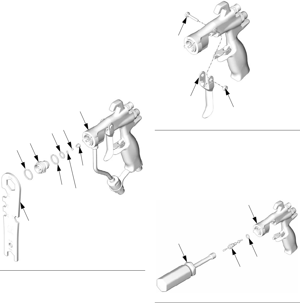
Complete Gun Packing Repair
Disassembly
Seat Repair
NOTE:
• See Repair Kits, page 20.
• Clean parts with a solvent that is compatible with
the parts and the fluid being sprayed.
1. Relieve the pressure, page 10. Remove the fluid
and air hoses from the gun.
2. Remove the air cap retaining ring (6), air cap (21),
and spray tip (33). See FIG. 35.
3. Trigger the gun to pull the needle housing off the
seat while you unscrew the diffuser (5) from the gun
body (1), using the gun tool (30).
4. Inspect the o-rings (5e*, 5f*, and 5g*) in place.
Carefully remove the o-rings from the diffuser hous-
ing (5a) and replace if necessary.
5. Remove the seat nut (5d), seat (5c) and seat gasket
(5b, carbide models only) using a 7/32 in. hex
wrench.
6. Inspect the seat (5c) and seat gasket (5b) and
replace if necessary.
FIG. 34
TI6576A
A
C
14
1
Torque to 90 in-lb
(10.5 N•m).
1
FIG. 35
TI6568A
21
33
6
Repair
3A0149C 21
7. Reinstall the seat gasket (5b, carbide models only),
seat (5c), and seat nut (5d). Torque to 45-50 in-lb.
Be sure not to overtighten the nut.
NOTE:
• When reinstalling the carbide seat (5c), the tapered
end of the seat (red side) must point toward the gun
tip.
• The plastic seat (5c, model 24C854 guns), can be
reinstalled in either direction. To avoid fluid leakage,
do not reverse the direction of the plastic seat (5c) if
it is worn. The seat must be replaced if it is worn.
Needle Repair
1. Remove the diffuser, see Seat Repair, page 20.
2. Remove the trigger pivot pin nut (14‡), pivot pin
(13‡), and trigger (3‡) using the gun tool (30) and
nut driver (29). See FIG. 37.
3. Remove the fluid needle assembly (2) from the front
of the gun by using the nut driver tool (29). If the
needle is bent or damaged, or the packing is worn
or leaking, replace the entire needle assembly. If
replacement is necessary, be sure to remove the
o-ring (2a*) as it may stick inside the gun body. See
FIG. 38.
FIG. 36
TI6572A
5a
1
30
5c
5g*
5f*
5e*
5d
5b
(carbide only)
FIG. 37
FIG. 38
TI6574A
14‡
13‡
3‡
TI6575A
2
29
1
2a*
Repair
22 3A0149C
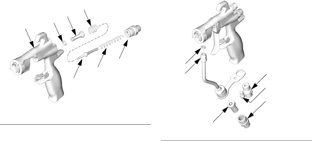
Air Valve Repair
1. Unscrew the spring cap (11) from the back of the
gun body (1) using the gun tool (30). Remove the
two springs (15 and 19) and the shaft (9).
2. Push the air valve assembly (8*) out the back of the
gun. See FIG. 39.
3. Inspect the u-cup (7*) in the gun body (1). If the
u-cup is worn or leaking, carefully remove the u-cup
from the front of the gun body, using a pick.
Fluid Tube Replacement
1. Remove the air inlet fitting (17) using the gun tool
(30) and remove the screw (20) using a 3/16 in. hex
wrench.
2. Unscrew the fluid inlet fitting (18). Remove and
clean or replace the inline fluid filter (12).
3. Unscrew the fluid tube connector (C) from the gun’s
fluid inlet. Carefully remove the gasket (22*).
FIG. 39
TI6577B
17*
9
11
15
19
8*
FIG. 40
TI6573A
22*
12
18
C17
20

Repair
3A0149C 23
Repair
24 3A0149C
Reassembly
NOTE: See Repair Kits, page 20.
1. Install the tube gasket (22*) in the gun. Handtighten
the fluid tube connector (C) into the gun’s fluid inlet.
Handtighten the air inlet fitting (17) and screw (20).
Torque the fluid tube connector to 150-160 in-lb
(17-18 N•m). Torque the air inlet fitting to
210-220 in-lb (24-25 N•m). Torque the fluid tube
bracket screw to 50-60 in-lb (6-7 N•m). See FIG. 43.
2. Install the inline fluid filter (12) into the base of the
fluid tube. Screw the fluid inlet fitting (18) into the
base of the tube. Torque to 175-185 in-lb
(20-21 N•m). See FIG. 43.
3. Place the new u-cup (7*) on the seal installation tool
(28*), with the u-cup lips facing the tool as shown in
FIG. 41. Push the u-cup into the back of the gun until
you feel a definite snap.
4. Lubricate the front end of the air valve assembly
(8*). Gently slide the air valve assembly into the
back of the gun, passing through the u-cup (7*), as
far as it will go. Be careful not to damage the u-cup.
See FIG. 43.
5. Carefully insert the thinner end of the shaft (9) into
the air valve (8*).
6. Install the two springs (15 and 19). Screw the spring
cap (11) into the back of the gun body. Torque to
210-220 in-lb (24-25 N•m).
7. Lightly lubricate the needle assembly o-rings and
shaft where the packing slides. Be sure that the
o-ring (2a*) is in place in the gun body (1).
8. Insert the fluid needle assembly (2) into the front of
the gun. Use the nut driver (29) to screw the fluid
needle assembly into the gun body (1) and torque to
50-60 in-lb (6-7 N•m). See FIG. 42.
9. Install the trigger (3), pivot pin (13), and nut (14).
Use low strength thread locker and be sure that the
brass piece of the fluid needle assembly (2) is
behind the trigger. See FIG. 43. Lubricate both sides
of the pivot pin where the trigger contacts the pin
and lubricate the boss on both sides of the gun
where the trigger contacts the gun body. Torque the
nut to 20-30 in-lb (2-3 N•m).
10. Trigger the gun to pull the needle back while you
screw the diffuser assembly (5) into the gun body
(1) using the gun tool (30). Torque to 155-165 in-lb
(18-19 N•m). When properly tightened, the flange
will bottom out on the gun.
11. Attach the retaining ring (6), air cap (21), and spray
tip (33).
FIG. 41
TI6578A
7*
28*
Lubricate lightly.
Lips face out of gun body.
3
8
3
8
FIG. 42
TI6575A
2†
29
1
2a*
Repair
3A0149C 25
FIG. 43
1
2
3
4
5a
6 (G15 only)
*7 *8
9
11
12
13
14
15
16
17
18
19
20
21
*22
33
6
*6b
*5e
*5f
*5g
5b✖ (carbide only)
5c†✖
5d†✖
4
6
6
3
7
*2a 3
1
5
3
3
3
TI6579D
10
9
1a
6 (G40 only)
10
11
*6a
Torque to 150-160 in-lb (17-18 N•m).
Lubricate lightly.
Torque to 155-165 in-lb (18-19 N•m).
Torque to 20-30 in-lb (2-3 N•m).
Do not lubricate diffuser o-rings.
Brass part must be behind trigger.
Lips face out of gun body.
Torque to 50-60 in-lb (6-7 N•m).
Torque to 210-220 in-lb (24-25 N•m).
Torque to 45-50 in-lb (5-6 N•m).
Use low-strength thread locker.
Torque to 175-185 in-lb (20-21 N•m).
1
3
4
5
6
7
8
9
10
11
12
13
21a (G15 only)
12
12
16
(24C853, 24C854 and
(24C856 &
24C857)
9
13
8
24C855 only)
(24C853, 24C854, and 24C855)
(24C853, 24C854, and 24C855)
*6a (G40 only)
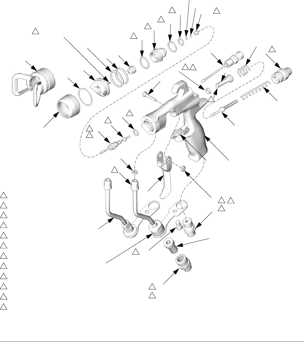
Parts
26 3A0149C
Parts
Part No. 24C853 and 24C854, G15 Gun
Part No. 24C855, G40 Gun
Part No. 24C856, G40 Gun, High Flow
1
2
3‡
4
5a
6 (G15 only)
*7 *8
9
11
13‡
14‡
15
17
19
21
*22
33
◆*6b
*5e
*5f
*5g
5b✖ (carbide only)
5c†✖
5d†✖
*2a
1a
6 (G40 only) ◆*6a
21a (G15 only)
TI6579D
29 30
28*
12
16
18
20
16
(24C856 only)
(24C853, 24C854, and
24C855 only)
(24C853, 24C854, and
24C855 only)
(24C853, 24C854, and
24C855 only)
*6a (G40 only)
Parts
3A0149C 27
Part No. 24C854, G15 Gun with Plastic Seat
Part No. 24C853, G15 Gun with Carbide Seat
▲Replacement Danger and Warning labels, tags, and
cards are available at no cost.
* Included in Seal Repair Kit 249422 (purchase
separately).
†Included in Plastic Seat Repair Kit 249424
(purchase separately).
✖Included in Carbide Seat Repair Kit 249456
(purchase separately).
‡Included in Trigger Repair Kit 249585
(purchase separately).
◆Included in Air Cap Seal Kit 253032
(purchase separately).
✓Not for sale separately.
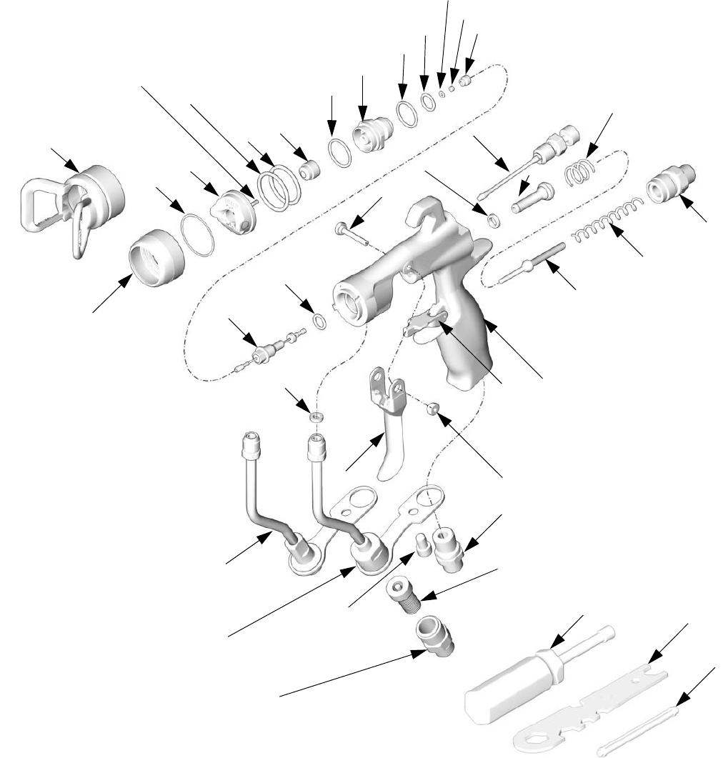
Ref.
No. Part No. Description Qty.
1BODY, gun 1
1a 249423 STOP, trigger 1
2 24B790 NEEDLE, assy; 3/32 ball; sst
includes items 2a (24C854 only)
and 9
1
24B789 NEEDLE, assy; 3/32 ball; carbide
includes items 2a (24C853 only)
and 9
1
2a*✓110004 PACKING, o-ring; PTFE 1
3‡ TRIGGER, gun 1
4 249135 VALVE, fan, assy 1
5 249132 DIFFUSER, assy (24C854 only) 1
249133 DIFFUSER, assy (24C853 only) 1
5a DIFFUSER, housing 1
5b✖288619 GASKET, seat; nylon (24C853
only)
1
5c† SEAT; plastic (24C854 only) 1
5c✖SEAT; carbide (24C853 only) 1
5d†✖NUT, seat 1
5e* 111116 PACKING, o-ring, seat; PTFE 1
5f*✓109450 PACKING, o-ring; PTFE 1
5g*✓111457 PACKING, o-ring; PTFE 1
6 24D438 RING, retaining; includes 6a and
6b
1
6a*◆✓ 109213 PACKING, o-ring; PTFE 1
6b*◆✓ 15G320 WASHER; PTFE 1
7*✓188493 PACKING, u-cup; UHMWPE 1
8* VALVE, air, assy 1
9 16A529 SHAFT, fluid spring 1
11 15F195 CAP, spring 1
12 224453 FILTER, tip (pkg of 5) 1
13‡ 15F739 PIN, pivot 1
14‡ 15F740 PIN, pivot, nut 1
15 114069 SPRING, compression 1
16 24D436 TUBE, assy.; includes item 22 1
17 15F202 FITTING, air inlet 1
18 24D437 FITTING, hose; see Accessories
for fitting with JIC threads
1
19 119767 SPRING, compression (24C854
only)
1
115141 SPRING, compression (24C853
only)
1
20 119996 SCREW, cap, socket hd; 1/4-20 x
3/8 in. (10 mm)
1
21 24C866 AIR CAP, includes item 21a 1
21a 24D627 PIN, air cap; indexing
(package of 3)
1
22*✓115133 GASKET, tube, acetal 1
28* TOOL, installation; seal 1
29 117642 TOOL, nut driver 1
30 15F446 TOOL, gun 1
31▲222385 CARD, warning (not shown) 1
32▲172479 TAG, warning (not shown) 1
33 SPRAY TIP, customer’s choice
33a 183616 GASKET, tip (not shown) 1
Ref.
No. Part No. Description Qty.
Parts
28 3A0149C
Part No. 24C855, G40 Gun with Standard Tip
Part No. 24C856, G40 Gun, High Flow
▲Replacement Danger and Warning labels, tags, and
cards are available at no cost.
* Included in Seal Repair Kit 249422 (purchase
separately).
✖Included in Carbide Seat Repair Kit 249456
(purchase separately).
‡Included in Trigger Repair Kit 249585
(purchase separately).
◆Included in Air Cap Seal Kit 253032
(purchase separately).
✓Not for sale separately.
Ref.
No. Part No. Description Qty.
1 BODY, gun 1
1a 249423 STOP, trigger 1
2 24B789 NEEDLE, assy; 3/32 ball; carbide
includes items 2a and 9
1
2a*✓110004 PACKING, o-ring; PTFE 1
3‡ TRIGGER, gun 1
4 249135 VALVE, fan, assy 1
5 249133 DIFFUSER, assy 1
5a DIFFUSER, housing 1
5b✖288619 GASKET, seat; nylon 1
5c✖SEAT; carbide 1
5d✖NUT, seat 1
5e* 111116 PACKING, o-ring, seat; PTFE 1
5f*✓109450 PACKING, o-ring; PTFE 1
5g*✓111457 PACKING, o-ring; PTFE 1
6 24D439 TIP GUARD, includes items 6a
and 6b (24C855 & 24C856 only)
1
6a*◆✓ 109213 PACKING, o-ring; PTFE 2
6b*◆✓ 15G320 WASHER; PTFE 1
7*✓188493 PACKING, u-cup; UHMWPE 1
8* VALVE, air, assy 1
9 16A529 SHAFT, fluid spring 1
11 15F195 CAP, spring 1
12 224453 FILTER, tip (pkg of 5, 24C855
only)
1
13‡ 15F739 PIN, pivot 1
14‡ 15F740 PIN, pivot, nut 1
15 114069 SPRING, compression 1
16 24D436 TUBE, assy, includes item 22
(24C855 only)
1
249317 TUBE, assy (24C856 only) 1
17 15F202 FITTING, air inlet 1
18 24D437 FITTING, hose (24C855 only);
see Accessories for fitting with
JIC threads.
1
19 115141 SPRING, compression 1
20 119996 SCREW, cap, socket hd; 1/4-20 x
3/8 in. (10 mm) (24C855 only)
1
21 249180 AIR CAP 1
22*✓115133 GASKET, tube, acetal 1
28* TOOL, installation; seal 1
29 117642 TOOL, nut driver 1
30 15F446 TOOL, gun 1
31▲222385 CARD, warning (not shown) 1
32▲172479 TAG, warning (not shown) 1
33 SPRAY TIP, customer’s choice
33a 183616 GASKET, tip (not shown) 1
Ref.
No. Part No. Description Qty.

Parts
3A0149C 29
Parts
30 3A0149C
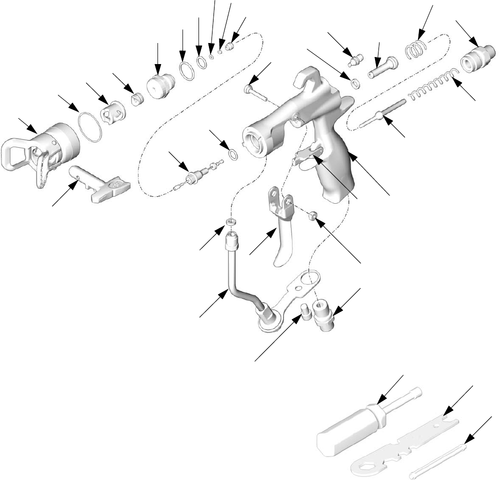
Part No. 24C857, G40 Gun with RAC Tip
1
2
3‡
★4
★5a *7 *8
9
11
13‡
14‡
15
16
17
19
20
*22
★*5f
★*5g
★✖5b
*2a
1a
TI7203B
29 30
28*
33a
★35
★6
33
★*6a
5c✖★
5d✖★
TI6580A
Parts
3A0149C 31
Part No. 24C857, G40 Gun with RAC Tip
▲Replacement Danger and Warning labels, tags, and
cards are available at no cost.
* Parts included in Seal Repair Kit 249422 (purchase
separately).
✖Parts included in Carbide Seat Repair Kit 249456
(purchase separately).
‡Parts included in Trigger Repair Kit 249585 (pur-
chase separately).
★Parts included in RAC Conversion Kit 24C791 (pur-
chase separately).
✓Not for sale separately.
Ref. No.Part No. Description Qty.
1 BODY, gun 1
1a 249423 STOP, trigger 1
2 24B789 NEEDLE, assy; 3/32 ball; carbide
includes items 2a and 9
1
2a*✓110004 PACKING, o-ring; PTFE 1
3‡ TRIGGER, gun 1
4★15G713 NUT, air plug 1
5★249877 DIFFUSER, assy, RAC 1
5a★DIFFUSER, housing 1
5b✖★ 288619 GASKET, seat; nylon 1
5c✖★ SEAT; carbide 1
5d✖★ NUT, seat 1
5e*★✓ 111116 PACKING, o-ring, seat; PTFE 1
5f*★✓ 109450 PACKING, o-ring; PTFE 1
5g*★✓ 111457 PACKING, o-ring; PTFE 1
6★24C921 TIP GUARD/AIR CAP ASSY,
includes item 35
1
6a*★✓ 109213 PACKING, o-ring, PTFE 1
7*✓188493 PACKING, u-cup; UHMWPE 1
8* VALVE, air, assy 1
9 16A529 SHAFT, fluid spring 1
11 15F195 CAP, spring 1
13‡ 15F739 PIN, pivot 1
14‡ 15F740 PIN, pivot, nut 1
15 114069 SPRING, compression 1
16 249317 TUBE, assy 1
17 15F202 FITTING, air inlet 1
19 115141 SPRING, compression 1
20 119996 SCREW, cap, socket hd; 1/4-20 x
3/8 in. (10 mm)
1
22*✓115133 GASKET, tube, acetal 1
28* TOOL, installation; seal 1
29 117642 TOOL, nut driver 1
30 15F446 TOOL, gun 1
31▲222385 CARD, warning (not shown) 1
32▲172479 TAG, warning (not shown) 1
33 SPRAY TIP, customer’s choice,
see tip selection chart page 32,
includes item 33a
1
33a 246453 RAC GASKET, standard, black 1
248936 RAC GASKET, solvent resistant,
orange
35★15F442 HOUSING, cylinder 1
Ref. No.Part No. Description Qty.
Spray Tip Selection Chart
32 3A0149C
Spray Tip Selection Chart
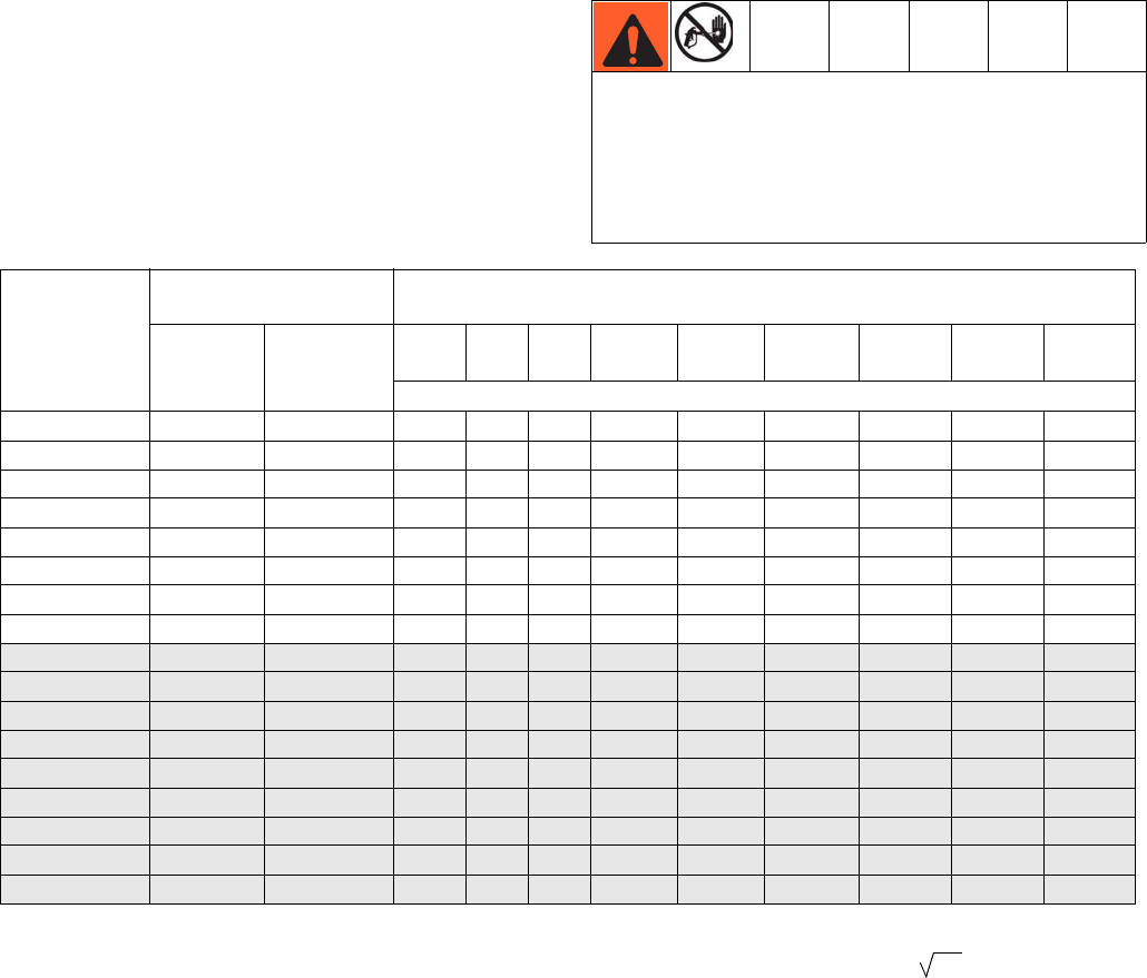
Spray Tips, for use with G15/G40 Air Cap
AAM Fine Finish Spray Tips
Recommended for high finish quality applications at low and medium pressures.
Order desired tip, Part No. AAMxxx, where xxx = 3-digit number from matrix below.
GG4 Industrial Spray Tips
Recommended for high wear applications at high pressures.
Order desired tip, Part No. GG4xxx, where xxx = 3-digit number from matrix below.
NOTE:
• All tips in the Spray Tip Selection Chart below can
be used with Model G40 guns. Use tips in the gray
shaded area of the chart with Model G40 guns only.
• Do not use tips in the gray shaded area of the chart
with Model G15 guns.
* Tips are tested in water.
†These tip sizes include a 150 mesh tip filter.
‡ Do not use these tips with Model G15 guns.
★GG4 tips only.
❄AAM tips only.
Do not use tips in the gray shaded area of the Spray
Tip Selection Chart with Model G15 guns. G15 guns
are not designed for use at high pressures. Failure to
follow this warning can result in serious injury, includ-
ing fluid injection and splashing in the eyes or on the
skin.
Orifice Size
in. (mm)
* Fluid Output
fl oz/min (lpm)
Maximum Pattern Width at 12 in. (305 mm)
in. (mm)
at 600 psi
(4.1 MPa,
41 bar)
at 1000 psi
(7.0 MPa,
70 bar)
2 to 4
(100)
4 to 6
(150)
6 to 8
(200)
8 to 10
(250)
10 to 12
(300)
12 to 14
(350)
14 to 16
(400)
16 to 18
(450)
18 to 20
(500)
Spray Tip
† 0.007 (0.178) 4.0 (0.1) 5.2 (0.15) ★107 207 307
† 0.009 (0.229) 7.0 (0.2) 9.1 (0.27) 109 209 309 409 509
† 0.011 (0.279) 9.5 (0.28) 12.5 (0.37) 111 211 311 411 511 611 ❄711
0.013 (0.330) 12.0 (0.35) 16.0 (0.47) 213 313 413 513 613 713
0.015 (0.381) 16.0 (0.47) 21.0 (0.62) 215 315 415 515 615 715 815
0.017 (0.432) 20.0 (0.59) 26.5 (0.78) 217 317 417 517 617 717 817 917
0.019 (0.483) 28.0 (0.8) 36.3 (1.09) 219 319 419 519 619 719 819 919
0.021 (0.533) 35.0 (1.0) 45.4 (1.36) 321 421 521 621 721 821 921
‡ 0.023 (0.584) 40.0 (1.2) 51.9 (1.56) 423 523 623 723 923
‡ 0.025 (0.635) 50.0 (1.5) 64.8 (1.94) 425 625 725 825 ★925
‡ 0.027 (0.686) 58.5 (1.7) 75.8 (2.27) 527 627 827
‡ 0.029 (0.737) 68.0 (1.9) 88.2 (2.65) 629
‡ 0.031 (0.787) 78.0 (2.2) 101.1 (3.03) 431 631
‡ 0.033 (0.838) 88.0 (2.5) 114.1 (3.42) 633 ★833
‡ 0.035 (0.889) 98.0 (2.8) 127.1 (3.81) 435
‡ 0.037 (0.940) 108.0 (3.1) 140.0 (4.20) 737
‡ 0.039 (0.991) 118.0 (3.4) 153.0 (4.59) 539 639 839
Fluid output (Q) at other pressures (P) can be calculated by this formula: Q = (0.041) (QT)
where QT = fluid output (fl oz/min) at 600 psi from the above table for the selected orifice size.
P
Spray Tip Selection Chart
3A0149C 33
AAF Fine Finish Pre-Orifice Spray Tips
Recommended for high finish quality applications at low and medium pressures. AAF tips have a pre-orifice that
assists in atomizing sheer thinning materials, including lacquers.
Order desired tip, Part No. AAFxxx, where xxx = 3-digit number from matrix below.
* Tips are tested in water.
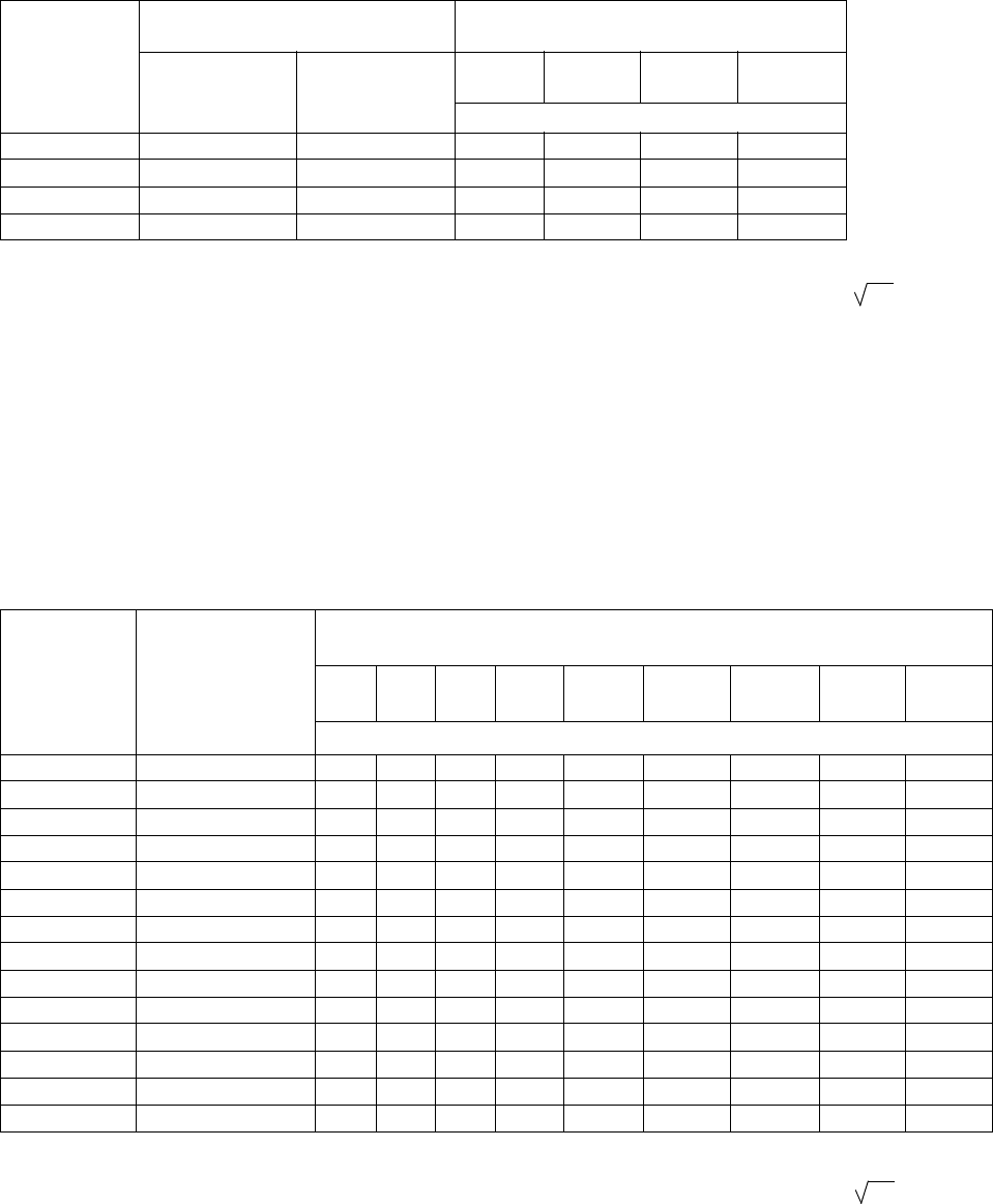
RAC SwitchTips, for use with G40 RAC Air Cap
NOTE: All tips in the Spray Tip Selection Charts below
can be used with Model G40 guns equipped with RAC
air cap 24C921.
NOTE: Tips are sometimes packaged with other promo-
tional parts intended for the airless market. Disregard
extra parts.
LTX RAC Spray Tips
Order desired tip, Part No. LTXxxx, where xxx = 3-digit number from matrix below.
* Tips are tested in water.
❖Measured with NO airflow. Air assist will tend to reduce pattern lengths by 1 in. to 2 in.
Orifice Size
in. (mm)
* Fluid Output
fl oz/min (lpm)
Maximum Pattern Width at 12 in. (305 mm)
in. (mm)
at 600 psi
(4.1 MPa, 41 bar)
at 1000 psi
(7.0 MPa, 70 bar)
6 to 8
(200)
8 to 10
(250)
10 to 12
(300)
12 to 14
(350)
Spray Tip
0.011 (0.279) 9.5 (0.28) 12.5 (0.37) 310 410 510 610
0.013 (0.330) 12.0 (0.35) 16.0 (0.47) 312 412 512 612
0.015 (0.381) 16.0 (0.47) 21.0 (0.62) 414 514 614
0.017 (0.432) 20.0 (0.59) 26.5 (0.78) 416 516 616
Fluid output (Q) at other pressures (P) can be calculated by this formula: Q = (0.041) (QT)
where QT = fluid output (fl oz/min) at 600 psi from the above table for the selected orifice size.
P
Orifice Size in.
(mm)
* Fluid Output,
at 2000 psi
(14.0 MPa, 140 bar)
fl oz/min (lpm)
❖ Maximum Pattern Width at 12 in. (305 mm)
in. (mm)
2 to 4
(100)
4 to 6
(150)
6 to 8
(200)
8 to 10
(250)
10 to 12
(300)
12 to 14
(350)
14 to 16
(400)
16 to 18
(450)
18 to 20
(500)
Spray Tip
0.009 (0.229) 11.2 (0.33) 109 209 309 409 509
0.011 (0.279) 16.6 (0.49) 111 211 311 411 511 611
0.013 (0.330) 23.3 (0.69) 213 313 413 513 613
0.015 (0.381) 30.8 (0.91) 115 215 315 415 515 615
0.017 (0.432) 39.5 (1.17) 217 317 417 517 617 817
0.019 (0.483) 49.7 (1.47) 219 319 419 519 619 819
0.021 (0.533) 60.5 (1.79) 221 321 421 521 621 721 821
0.023 (0.584) 72.7 (2.15) 323 423 523 623 723
0.025 (0.635) 85.9 (2.54) 225 325 425 525 625
0.027 (0.686) 100.0 (2.96) 227 327 427 527 627 827
0.029 (0.737) 115.6 (3.42) 329 429 529 629 729
0.031 (0.787) 131.8 (3.90) 231 331 431 531 631 831
0.033 (0.838) 149.4 (4.42) 433 533 633 833
0.035 (0.889) 168.4 (4.98) 235 335 435 535 635 735 835
Fluid output (Q) at other pressures (P) can be calculated by this formula: Q = (0.041) (QT)
where QT = fluid output (fl oz/min) from the above table for the selected orifice size.
P

Spray Tip Selection Chart
34 3A0149C
RAC SwitchTips, for use with G40 RAC Air Cap, Continued
NOTE: All tips in the Spray Tip Selection Charts below
can be used with Model G40 guns equipped with RAC
air cap 24C921.
FFT Fine Finish RAC Spray Tips
Order desired tip, Part No. FFTxxx, where xxx = 3-digit number from matrix below.
WRX WideRAC Spray Tips
Order desired tip, Part No. WRxxxx, where xxxx = 4-digit number from matrix below.
* Tips are tested in water.
❖Measured with NO airflow. Air assist will tend to reduce pattern lengths by 1 in. to 2 in.
Orifice Size in.
(mm)
* Fluid Output at
2000 psi (14.0 MPa, 140 bar)
fl oz/min (lpm)
❖ Maximum Pattern Width at 12 in. (305 mm)
in. (mm)
4 to 6
(150)
6 to 8
(200)
8 to 10
(250)
10 to 12
(300)
12 to 14
(350)
Spray Tip
0.008 (0.203) 8.8 (0.26) 208 308
0.010 (0.254) 13.9 (0.41) 210 310 410 510
0.012 (0.305) 19.9 (0.59) 212 312 412 512 612
0.014 (0.356) 27.0 (0.80) 214 314 414 514 614
Orifice Size
in. (mm)
* Fluid Output at
2000 psi (14.0 MPa, 140 bar)
fl oz/min (lpm)
❖ Maximum Pattern Width at 12 in. (305 mm)
24 in. (610 mm)
Spray Tip
0.021 (0.533) 60.5 (1.79) 1221
0.023 (0.584) 72.7 (2.15) 1223
0.025 (0.635) 85.9 (2.54) 1225
0.027 (0.686) 100.0 (2.96) 1227
0.029 (0.737) 115.6 (3.42) 1229
0.031 (0.787) 131.8 (3.90) 1231
0.033 (0.838) 149.4 (4.42) 1233
0.035 (0.889) 168.3 (4.98) 1235
0.037 (0.940) 187.9 (5.56) 1237
0.039 (0.991) 208.9 (6.18) 1239
Fluid output (Q) at other pressures (P) can be calculated by this formula: Q = (0.041) (QT)
where QT = fluid output (fl oz/min) from the above table for the selected orifice size.
P
Accessories
3A0149C 35
Accessories
Use Only Genuine Graco Parts and Accessories
Air Fitting and Tubing Kit 249473
Alternative-style connector for air inlet and hose. 3/8 in.
to 1/4 npt(f) Push-To-Lock fitting, 25 ft (7.62 m) long, 3/8
in. (9.5 mm) ID, nylon tubing.
Air Hose 241811
100 psi (0.7 MPa, 7 bar) Maximum Working Pressure
1/4-18 npsm(fbe), 1/4 in. (6 mm) ID, 25 ft (7.62 m) long
polyurethane tubing.
Air Line Quick Disconnect
208536 Air Line Quick Disconnect Coupling
169967 Air Line Quick Disconnect Pin
Fluid Filter Kits
224453 100 mesh (.005 gap spacing) replacement
fluid filters. Quantity. of 5.
238563 60 mesh (.009 gap spacing) replacement
fluid filters for coarser particle filtering to
replace standard 100 mesh filters. Quan-
tity of 3.
Fluid Hose 241812
3500 psi (24 MPa, 242 bar) Maximum Working Pressure
1/4-18 npsm(fbe), 3/16 in. (5 mm) ID, 25 ft (7.62 m) long,
nylon tubing with polyurethane cover.
Fluid Swivel Connector 189018
5800 psi (40 MPa, 400 bar) Maximum Working Pressure
Connector to ease movement of the gun and fluid hose.
1/4-18 npsm. 17-4 PH SST wetted parts.
Gun Brush 101892
Use to clean the gun.
G15 Gun Flush Box Insert 15G093
Insert for use with Gun Flush Box 244105 and G15
Spray Guns.
G40 Gun Flush Box Insert 15G346
Insert for use with Gun Flush Box 244105 and G40
Spray Guns.
Gun Lubricant 111265
One 4 oz. (113 g) tube sanitary (non-silicone) lubricant
for fluid seals and wear areas.
High Pressure Fluid Ball Valve 238694
5000 psi (35 MPa, 350 bar) Maximum Working Pressure
3/8 npt(mbe). SST wetted parts, PEEK seats, PTFE
seals. Compatible with acid-catalyzed materials. Can be
used as fluid drain valve.
HVLP Verification Kit 24C788
Use to check air cap air pressure at various air supply
air pressures. Do not use for actual spraying.
NOTE: To be HVLP compliant, the atomizing air pres-
sure must not exceed 10 psi (70 kPa, 0.7 bar).
RAC Gasket 246453
Pack of five standard replacement RAC gaskets (item
33a).
Acetal RAC Gasket 248936
Pack of five plastic (acetal) replacement RAC gaskets
(item 33a).
G40 RAC Conversion Kit 24C791
Kit includes parts to convert a standard G40 gun to a
RAC gun. LTX spray tip not included.
Air Cap Lacquer Kit 289080
Kit includes air cap optimized to spray lacquer.
Air Cap Seal Kit 253032
Pack of five seals and five o-rings for the air cap assy.
Seal Repair Kit 249422
Kit includes replacement o-rings, gasket, u-cup, air
valve assembly, and seal installation tool.
Accessories
36 3A0149C
Plastic Seat Repair Kit 249424
Kit includes replacement plastic seat (pack of 10), and
seat nut for Model G15 gun.
SST Seat Repair Kit 287962
Kit includes assembled diffuser with SST seat for use
with pigmented acid catalyzed materials. For use with
gun 24C854 only.
Carbide Seat Repair Kit 249456
Kit includes replacement carbide seat, seat gasket, and
seat nut for Model G40 gun. Kit also can be used with
Model G15 guns.
Carbide Seat Gasket Kit 288619
Kit includes replacement nylon seat gaskets (qty. of ten)
for Model G40 guns and G15 guns with a carbide seat.
Tip Filter Kit 241804
Replacement filters for spray tip orifice sizes 0.007,
0.009, and 0.011. Quantity of 10.
Trigger Repair Kit 249585
Kit includes replacement trigger, pivot pins (qty. of 5),
and pivot pin nuts (qty. of 5).
Trigger Stop Kit 249423
Kit includes replacement trigger stop and pin.
Ultimate Gun Cleaning Kit 15C161
Kit includes brushes and tools for gun maintenance.
Unclogging Needle Kit 249598
Kit includes picks for unclogging gun tip.
Fan Valve Fine Adjustment Kit 289499
Kit includes a replacement fan valve assembly with
more adjustment accuracy.
Fluid Fitting Kit 24C356, JIC Threads
Kit includes a 1/2-20 JIC threaded fluid inlet fitting.

Accessories
3A0149C 37
Part Interchangeability Guide
NOTE: The new retaining ring is black and has coarse threads, while the old retaining ring is silver and has fine
threads. Any interchange will damage the threads on the ring and gun body.
*Older model part numbers include 288xxx, 287xxx, 249xxx.
Description
Part Number
New Models
(24Cxxx)
Part Number,
Older Models* Interchangeable?
Fluid spring shaft 16A529 15F193
15F194
Yes 16A529 combines the fluid spring shaft and seat
into a single part. Directly replaceable.
Locating pin
24D627 15G618 No New pin is shorter to match the new gun body.
Using a new pin/air cap combo on an old model
gun results in loss of the alignment feature.
Using an old pin/air cap combo on a new model
gun causes leakage due to improper fit.
G15 retaining ring kit
Includes retaining ring,
PTFE o-ring, and PTFE
washer
24D438 15F192 No See note below table.
G40 retaining ring/tip
guard kit
Includes retaining ring
with guard, PTFE o-ring,
and PTFE washer
24D439 249256 No See note below table
RAC seat housing
15F442 15J770 No Works properly only with RAC Tip Guard/Air Cap
Assembly 24C921 and is included in that kit.
Seat will fit into older model assemblies, but
spray performance may be affected.
AA RAC guard kit
Includes guard assembly
(with retaining ring) and
mating cylinder housing.
24C921 288465 No See note below table.
Needle, carbide ball,
G15 and G40
24B789 288559 Yes Directly replaceable.
Needle, stainless steel
ball, G15
24B790 288558 Yes Directly replaceable.
HVLP verification kit 24C788 249140 No See note below table.
RAC gun conversion kit 24C791 287917 No Can only be used on the new gun due to a differ-
ent RAC guard. See note below table.
G15 air cap 24C866 249596 No Uses new shorter locating pin. See note for
Locating pin, this table.
Fluid tube assembly
24D436 249136 Yes The new fluid tube assembly will fit an older gun
only if a new fluid fitting is purchased, 24D437
(standard threads) or 24C356 (JIC threads).
Fluid fitting,
standard threads
24D437 15F186 No New fluid fittings have different threads that fit
only the new fluid tube assembly (24D436). Any
interchange will damage the threads.
Fluid fitting,
JIC threads
24C356 NA No
Dimensions
38 3A0149C
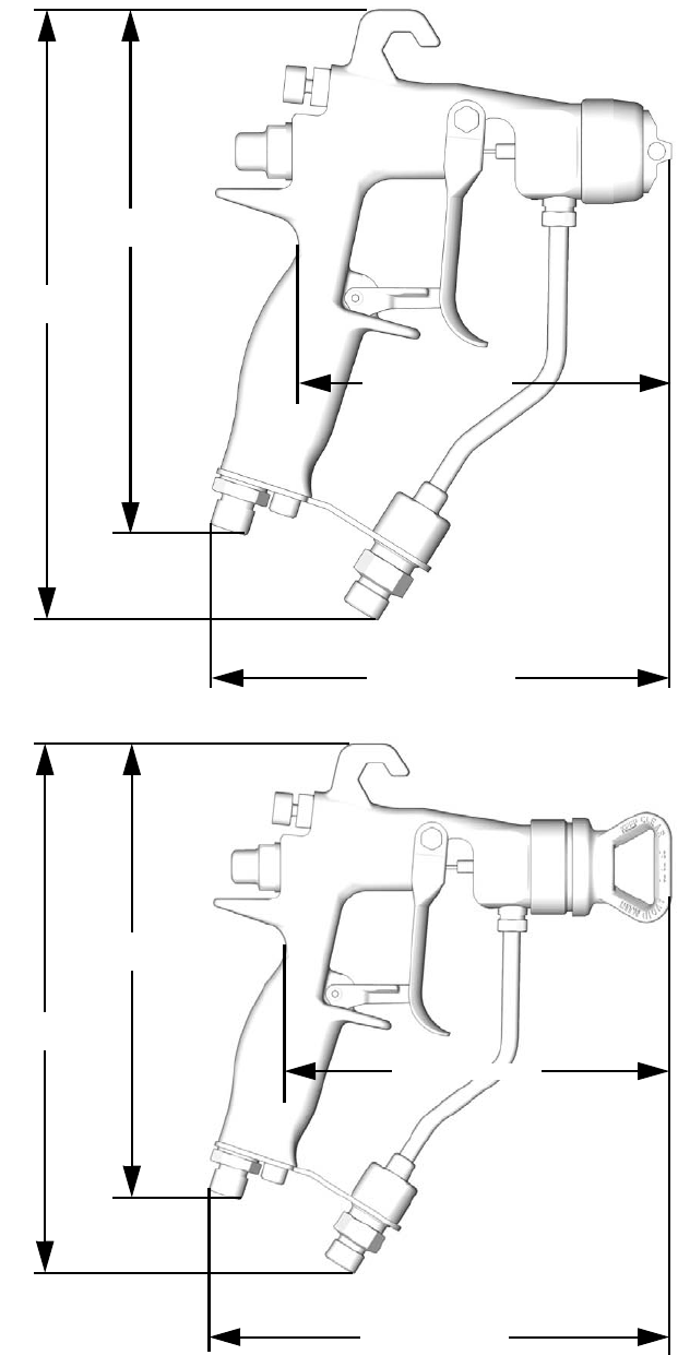
Dimensions
6.1 in. (15.5 cm)
8.0 in.
(20.3 cm)
6.9 in.
(17.5 cm)
5.0 in. (12.7 cm)
Model G15
TI6583A
6.9 in. (17.5 cm)
5.8 in. (14.7 cm)
8.0 in.
(20.3 cm)
6.9 in.
(17.5 cm)
Model G40
TI6845A
Technical Data
3A0149C 39
Technical Data
* All readings were taken with the fan valve fully closed (full fan size), at 20 psi (140 kPa, 1.4 bar) and 100 psi (0.7
kPa, 7 bar), and at the assumed operator position. Sound Power was tested to ISO 9614-2.
Category Data
Maximum Working Fluid Pressure . . . . . . . . . . . . . . . . . . Model G15: 1500 psi (10 MPa, 105 bar)
Model G40: 4000 psi (28 MPa, 280 bar)
Maximum Working Air Pressure . . . . . . . . . . . . . . . . . . . . 100 psi (0.7 MPa, 7 bar)
Maximum Gun Inlet Air Pressure for HVLP Operation . . . 14 psi (0.098 MPa, 0.98 bar)
Maximum Working Fluid Temperature . . . . . . . . . . . . . . . 110°F (43°C)
Fluid Inlet . . . . . . . . . . . . . . . . . . . . . . . . . . . . . . . . . . . . . 1/4-18 npsm
Air Inlet . . . . . . . . . . . . . . . . . . . . . . . . . . . . . . . . . . . . . . . 1/4-18 npsm (R1/4-19) compound male thread
Gun Weight. . . . . . . . . . . . . . . . . . . . . . . . . . . . . . . . . . . . 16 oz (450 grams)
*Sound Pressure at 20 psi (140 kPa, 1.4 bar) . . . . . . . . . 66.9 dB(A)
*Sound Pressure at 100 psi (0.7 kPa, 7 bar) . . . . . . . . . . 80.0 dB(A)
*Sound Power at 20 psi (140 kPa, 1.4 bar) . . . . . . . . . . . 76.8 dB(A)
*Sound Power at 100 psi (0.7 kPa, 7 bar) . . . . . . . . . . . . 89.9 dB(A)
Wetted Parts. . . . . . . . . . . . . . . . . . . . . . . . . . . . . . . . . . . Stainless Steel, Carbide, Ultra High Molecular Weight
Polyethylene, Engineered Plastic, PTFE, Nylon, Fluoro-
elastomer
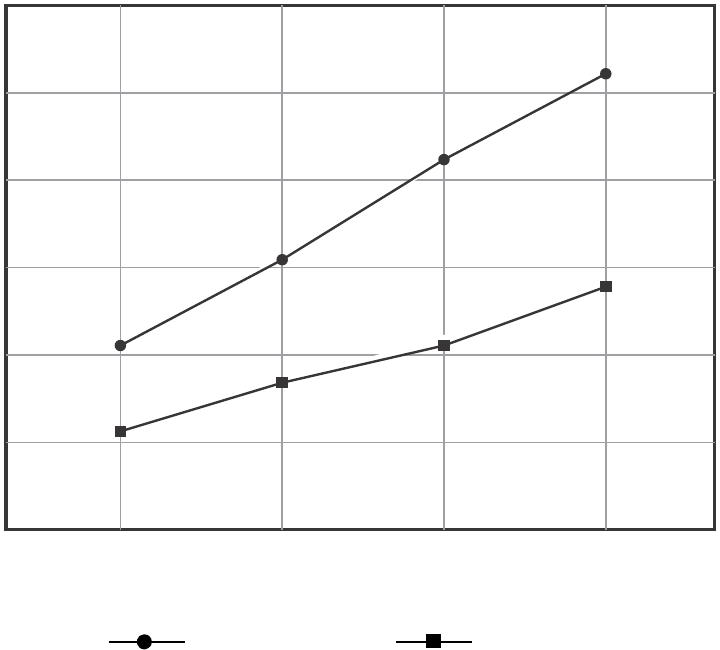
Air Flow, Standard Air Cap
Gun Inlet Pressure (PSI)
10 20 30 400
0
2
4
6
8
10
50
12
Air Flow
(SCFM)
4.2
6.4
8.6
10.6
5.8
4.6
3.8
2.6
Fan Valve Open Fan Valve Closed

All written and visual data contained in this document reflects the latest product information available at the time of publication.
Graco reserves the right to make changes at any time without notice.
Original instructions. This manual contains English. MM 3A0149
Graco Headquarters: Minneapolis
International Offices: Belgium, China, Japan, Korea
GRACO INC. P.O. BOX 1441 MINNEAPOLIS, MN 55440-1441
Copyright 2009, Graco Inc. is registered to ISO 9001
www.graco.com
Revised 05/2010
Graco Standard Warranty
Graco warrants all equipment referenced in this document which is manufactured by Graco and bearing its name to be free from defects in
material and workmanship on the date of sale to the original purchaser for use. With the exception of any special, extended, or limited warranty
published by Graco, Graco will, for a period of twelve months from the date of sale, repair or replace any part of the equipment determined by
Graco to be defective. This warranty applies only when the equipment is installed, operated and maintained in accordance with Graco’s written
recommendations.
This warranty does not cover, and Graco shall not be liable for general wear and tear, or any malfunction, damage or wear caused by faulty
installation, misapplication, abrasion, corrosion, inadequate or improper maintenance, negligence, accident, tampering, or substitution of
non-Graco component parts. Nor shall Graco be liable for malfunction, damage or wear caused by the incompatibility of Graco equipment with
structures, accessories, equipment or materials not supplied by Graco, or the improper design, manufacture, installation, operation or
maintenance of structures, accessories, equipment or materials not supplied by Graco.
This warranty is conditioned upon the prepaid return of the equipment claimed to be defective to an authorized Graco distributor for verification of
the claimed defect. If the claimed defect is verified, Graco will repair or replace free of charge any defective parts. The equipment will be returned
to the original purchaser transportation prepaid. If inspection of the equipment does not disclose any defect in material or workmanship, repairs will
be made at a reasonable charge, which charges may include the costs of parts, labor, and transportation.
THIS WARRANTY IS EXCLUSIVE, AND IS IN LIEU OF ANY OTHER WARRANTIES, EXPRESS OR IMPLIED, INCLUDING BUT NOT LIMITED
TO WARRANTY OF MERCHANTABILITY OR WARRANTY OF FITNESS FOR A PARTICULAR PURPOSE.
Graco’s sole obligation and buyer’s sole remedy for any breach of warranty shall be as set forth above. The buyer agrees that no other remedy
(including, but not limited to, incidental or consequential damages for lost profits, lost sales, injury to person or property, or any other incidental or
consequential loss) shall be available. Any action for breach of warranty must be brought within two (2) years of the date of sale.
GRACO MAKES NO WARRANTY, AND DISCLAIMS ALL IMPLIED WARRANTIES OF MERCHANTABILITY AND FITNESS FOR A
PARTICULAR PURPOSE, IN CONNECTION WITH ACCESSORIES, EQUIPMENT, MATERIALS OR COMPONENTS SOLD BUT NOT
MANUFACTURED BY GRACO. These items sold, but not manufactured by Graco (such as electric motors, switches, hose, etc.), are subject to
the warranty, if any, of their manufacturer. Graco will provide purchaser with reasonable assistance in making any claim for breach of these
warranties.
In no event will Graco be liable for indirect, incidental, special or consequential damages resulting from Graco supplying equipment hereunder, or
the furnishing, performance, or use of any products or other goods sold hereto, whether due to a breach of contract, breach of warranty, the
negligence of Graco, or otherwise.
FOR GRACO CANADA CUSTOMERS
The Parties acknowledge that they have required that the present document, as well as all documents, notices and legal proceedings entered into,
given or instituted pursuant hereto or relating directly or indirectly hereto, be drawn up in English. Les parties reconnaissent avoir convenu que la
rédaction du présente document sera en Anglais, ainsi que tous documents, avis et procédures judiciaires exécutés, donnés ou intentés, à la suite
de ou en rapport, directement ou indirectement, avec les procédures concernées.
Graco Information
For the latest information about Graco products, visit www.graco.com.
TO PLACE AN ORDER, contact your Graco distributor or call to identify the nearest distributor.
Phone: 612-623-6921 or Toll Free: 1-800-328-0211, Fax: 612-378-3505
