Graco 24R491 3A1211M SaniForce Air Motors, Instructions/Parts, English User Manual To The 1122723d 22f9 4e51 A73f 4215ec38c77e
User Manual: Graco 24R491 to the manual
Open the PDF directly: View PDF ![]() .
.
Page Count: 22
Instructions/Parts
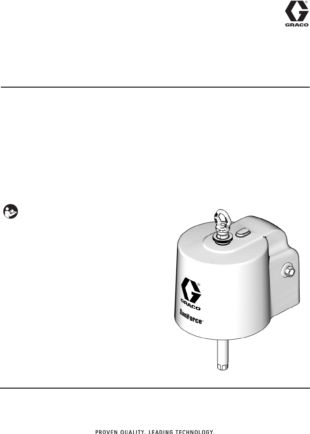
SaniForce™Air Motors 3A1211M
EN
For use on SaniForce™piston pumps, which are used to transfer medium to high viscosity
fluids in applications requiring high sanitation. For professional use only.
Model 24G785, Series A, 3.5 in. Air Motor
Model 24G786, Series A, 6.0 in. Air Motor
Model 24G787, Series A, 7.5 in. Air Motor
Model 24R491, Series A, 6.0 in. Air Motor
Model 24R015, Series A, 7.5 in. Air Motor
Model 24W754, Series A, 6.0 in. Air Motor
See page 5 for model information, including maximum
air inlet pressure.
.
Important Safety Instructions
Read all warnings and instructions in this manual.
For complete warnings and instructions see your
pump or package manual. Hazard symbols refer to
specific procedure risks. Save all instructions.
ti16220a
Air Motor shown with
Shrouds and Lift Ring
(see page 5)

Related Manuals
23A1211M
Contents
RelatedManuals ...........................2
Warnings .................................3
Models ...................................5
Component Identification ....................6
Grounding ..............................6
Troubleshooting ............................7
Repair ....................................8
Preventive Maintenance Schedule ...........8
Pressure Relief Procedure .................8
Remove the Shroud ......................8
Repair Air Valve ..........................9
Replace Pilot Valves .....................11
Repair Air Motor ........................12
AttachtheShroud .......................13
Parts ....................................14
Air Motor Parts — All Models ..............15
Shroud Kits, Fittings, and Fasteners* ........16
Air Motor Seal Kits .......................17
Model 24A352 Air Valve Parts ..............17
AirValveKits ...........................18
Dimensions ...............................19
TechnicalData ............................21
Graco Standard Warranty ...................22
Related Manuals
Manual Description
3A0733 SaniForce 6:1 Sanitary Pump
3A0734 SaniForce 5:1 Sanitary Pump
3A0735 SaniForce 12:1 Sanitary Pump
3A0591 SaniForce Sanitary Ram Modules
311163 SaniForce Bin Evacuation System
Warnings
3A1211M 3
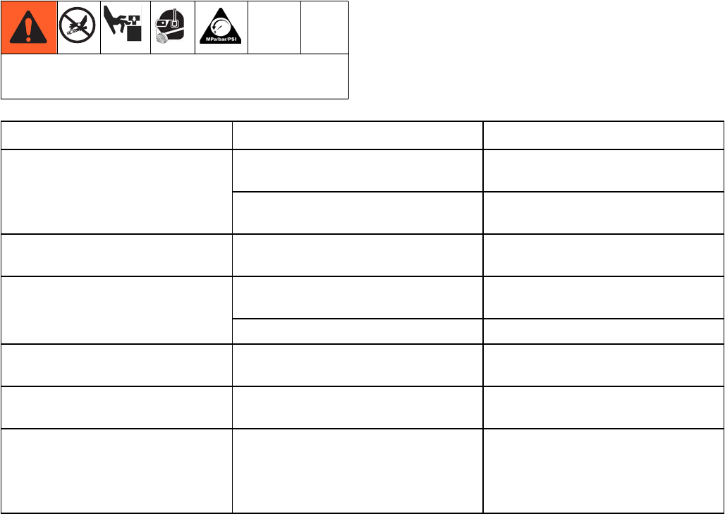
Warnings
The following warnings are for the setup, use, grounding, maintenance, and repair of this equipment. The exclama-
tion point symbol alerts you to a general warning and the hazard symbol refers to procedure-specific risk. When
these symbols appear in the body of this manual, refer back to these warnings. Additional, product-specific warnings
may be found throughout the body of this manual where applicable.
WARNINGWARNINGWARNING
WARNING
+
SKIN INJECTION HAZARD
High-pressure fluid from dispensing device, hose leaks, or ruptured components will pierce skin. This may
look like just a cut, but it is a serious injury that can result in amputation. Get immediate surgical
treatment.
• Do not point dispensing device at anyone or at any part of the body.
• Do not put your hand over the fluid outlet.
• Do not stop or deflect leaks with your hand, body, glove, or rag.
• Follow the Pressure Relief Procedure when you stop dispensing and before cleaning, checking, or
servicing equipment.
• Tighten all fluid connections before operating the equipment.
• Check hoses and couplings daily. Replace worn or damaged parts immediately.
MOVING PARTS HAZARD
Moving parts can pinch, cut or amputate fingers and other body parts.
• Keep clear of moving parts.
• Do not operate equipment with protective guards or covers removed.
• Pressurized equipment can start without warning. Before checking, moving, or servicing equipment,
follow the Pressure Relief Procedure and disconnect all power sources.
FIRE AND EXPLOSION HAZARD
Flammable fumes, such as solvent and paint fumes, in work area can ignite or explode. To help prevent
fire and explosion:
• Use equipment only in well ventilated area.
• Eliminate all ignition sources; such as pilot lights, cigarettes, portable electric lamps, and plastic drop
cloths (potential static arc).
• Keep work area free of debris, including solvent, rags and gasoline.
• Do not plug or unplug power cords, or turn power or light switches on or off when flammable fumes are
present.
• Ground all equipment in the work area. See Grounding instructions.
• Use only grounded hoses.
• Hold gun firmly to side of grounded pail when triggering into pail.
• If there is static sparking or you feel a shock, stop operation immediately. Do not use equipment until
you identify and correct the problem.
• Keep a working fire extinguisher in the work area.
Warnings
43A1211M
EQUIPMENT MISUSE HAZARD
Misuse can cause death or serious injury.
• Do not operate the unit when fatigued or under the influence of drugs or alcohol.
• Do not exceed the maximum working pressure or temperature rating of the lowest rated system
component. See Technical Data in all equipment manuals.
• Use fluids and solvents that are compatible with equipment wetted parts. See Technical Data in all
equipment manuals. Read fluid and solvent manufacturer’s warnings. For complete information about
your material, request MSDS from distributor or retailer.
• Do not leave the work area while equipment is energized or under pressure. Turn off all equipment and
follow the Pressure Relief Procedure when equipment is not in use.
• Check equipment daily. Repair or replace worn or damaged parts immediately with genuine
manufacturer’s replacement parts only.
• Do not alter or modify equipment.
• Use equipment only for its intended purpose. Call your distributor for information.
• Route hoses and cables away from traffic areas, sharp edges, moving parts, and hot surfaces.
• Do not kink or over bend hoses or use hoses to pull equipment.
• Keep children and animals away from work area.
• Comply with all applicable safety regulations.
PERSONAL PROTECTIVE EQUIPMENT
You must wear appropriate protective equipment when operating, servicing, or when in the operating area
of the equipment to help protect you from serious injury, including eye injury, hearing loss, inhalation of
toxic fumes, and burns. This equipment includes but is not limited to:
• Protective eyewear, and hearing protection.
• Respirators, protective clothing, and gloves as recommended by the fluid and solvent manufacturer.
WARNINGWARNINGWARNING
WARNING
Models
3A1211M 5
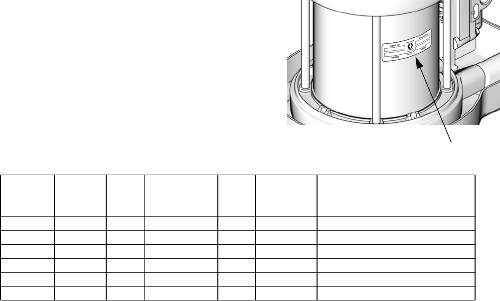
Models
Check your motor’s identification plate (ID) for the 6-digit part
number of your motor.
ti16228a
Air Motor
Part
Number
Air Motor
in Kit with
Shrouds Series
Displacement
(cc per cycle)
Stroke
(in.)
Piston
Diameter,
in. (mm)
Maximum Air Inlet Pressure
psi (MPa, bar)
24G785 24J765 A 800 4.75 3.5 (89) 100 psi (0.7 MPA, 7.0 bar)
24G786 24J764 A 2200 4.75 6.0 (152) 100 psi (0.7 MPA, 7.0 bar)
24G787 24J760 A 3500 4.75 7.5 (191) 100 psi (0.7 MPA, 7.0 bar)
24R491 ----- A 2200 4.75 6.0 (152) 100 psi (0.7 MPA, 7.0 bar)
24R015 ----- A 3500 4.75 7.5 (191) 100 psi (0.7 MPA, 7.0 bar)
24W754 ----- A 2200 4.75 6.0 (152) 100 psi (0.7 MPA, 7.0 bar)
ID
Component Identification
63A1211M
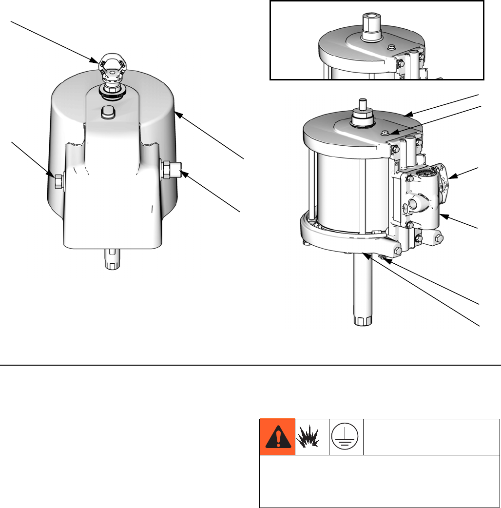
Component Identification
Key:
Air Motor Kit Components
A Air valve
B Pilot valve (bottom pilot valve is out of view)
C Top cover
D Bottom cover
E Manifold
F Ground screw
Lift Ring, Shrouds, and Fittings
G Air inlet, 1/2 in. npt(f)
H Air outlet, 3/4 in. npt
J Lift Ring
K Upper Shroud
L Lower Shroud (out of view)
Grounding
See FIG. 1. Connect a ground wire (Graco PN 238909)
to the ground screw (12) on the bottom cover of the air
motor, under the shroud. Connect the other end of the
ground wire to a true earth ground.
FIG. 1. SaniForce Air Motor components
A
H
G
B
F
C
ti16221a
ti16222a
J
K
D
E
Model
24R491
ti21099a
The equipment must be grounded. Grounding reduces
the risk of static and electric shock by providing an
escape wire for the electrical current due to static build
up or in the event of a short circuit.
Troubleshooting
3A1211M 7
Troubleshooting
NOTE: Check all possible problems and causes before
disassembling the pump.
Relieve the pressure before checking or servicing
the equipment.
Problem Cause Solution
Air motor will not run. Damaged air valve (17). Replace or service air valve (17).
See page 9.
Damaged pilot valve (19). Replace pilot valves (19). See page
11.
Air continuously exhausting
around air motor piston rod.
Damaged u-cups (3, 33). Replace piston rod u-cups (3, 33).
See page 12.
Air continuously exhausting from
muffler.
Damaged air valve plate (105) or cup
(112).
Replace or service air valve (17).
See page 9.
Damaged piston o-ring (8). Replace seals. See page 12.
Air motor “bounces” at top of
stroke.
Damaged bottom pilot valve. Replace bottom pilot valve (19). See
page 11.
Air motor “bounces” at bottom of
stroke.
Damaged top pilot valve. Replace top pilot valve (19). See
page 11.
Icing inside motor. Air motor operating at high pressure
or high cycle rate.
Reduce pressure, cycle rate, or duty
cycle of motor.
Reduce dew point of compressed
air in moisture coalescing filter.
Repair
83A1211M
Repair
Preventive Maintenance
Schedule
The operating conditions of your system determine how
often maintenance is required. Establish a preventive
maintenance schedule by recording when and what kind
of maintenance is needed, and then determine a regular
schedule for checking your system.
Pressure Relief Procedure
1. Shut off the air supply to the pump.
2. Close the bleed-type master valve (required in sys-
tem).
3. Open the fluid ball valve and/or dispensing valve to
relieve fluid pressure.
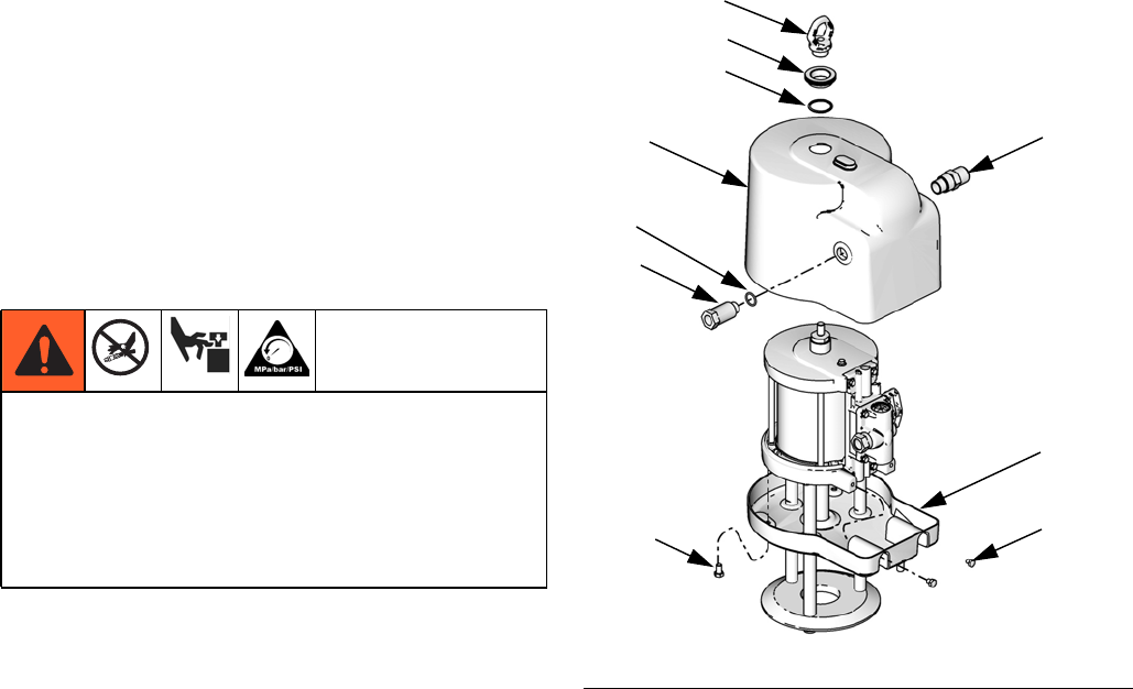
Remove the Shroud
1. Stop the pump at the middle of its stroke. Follow
Pressure Relief Procedure, page 8.
2. Disconnect air lines.
3. Remove exhaust fitting (42) and air inlet fitting (43)
with o-ring (44).
4. Remove the lift ring (41), hand screw (40), and
o-ring (39).
5. Lift the top shroud (46) straight up off the motor.
6. Remove four screws (48). Slide the bottom shroud
(47) down.
• Trapped air can cause the pump to cycle unexpect-
edly, which could result in serious injury from skin
injection or moving parts.
• Relieve pressure when you stop pumping and
before cleaning, checking, or servicing equipment.
• Do not lift or move motor while pressurized.
FIG. 2. Shroud removal
ti16226a
43
42
41
40
39
46
47
48
48
44
Repair
3A1211M 9
Repair Air Valve
Replace Complete Air Valve
1. Stop the pump at the middle of its stroke. Follow
Pressure Relief Procedure, page 8.
2. Disconnect air lines.
3. See Remove the Shroud, page 8.
NOTE: You do not need to remove the bottom shroud to
replace or repair the air valve.
4. See Parts, page 14. Remove screws (18). Remove
the air valve (17) and gasket (16*◆).
5. To repair the air valve, go to Disassemble the Air
Valve, step 1. To install a replacement air valve,
continue with Step 6.
6. Lubricate and align the new air valve gasket (16*◆)
on the manifold.
7. Lubricate the air valve plate (105◆), then attach the
air valve (17). Torque screws to 95-105 in-lb
(11-12 N•m).
8. See Attach the Shroud, page 13.
Replace Seals or Rebuild Air Valve
NOTE:
• Air Valve Seal Kits are available. See page 18 to
order the correct kit for your pump. Parts are marked
with an †.
• Air Valve Repair Kits are available. See page 18 to
order the correct kit for your pump. Parts are marked
with an ◆.
• Air Valve End Cap Kits are available. See page 18 to
order the correct kit for your pump. Parts are marked
with an ✠.
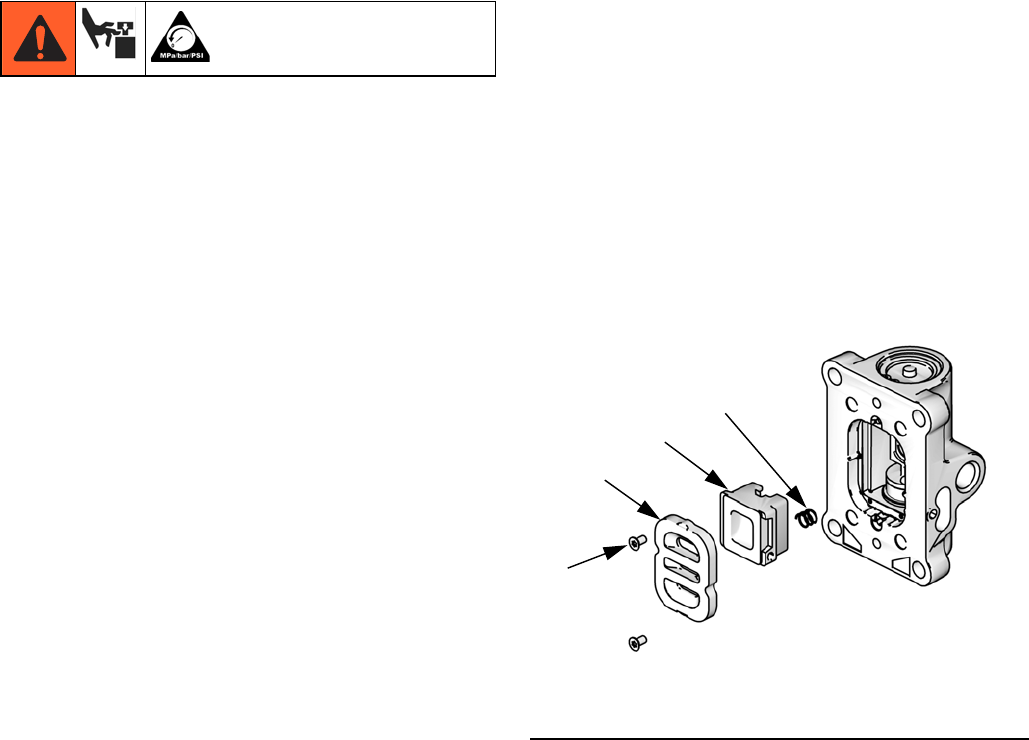
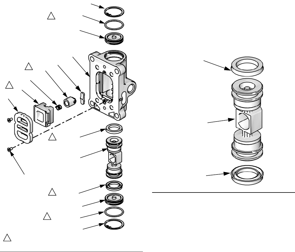
Disassemble the Air Valve
1. Perform steps 1-4 under Replace Complete Air
Valve, page 9.
2. See FIG.3.Usea2mmor5/64hexkeytoremove
two screws (109†◆). Remove the valve plate
(105◆), cup (112◆), and spring (111◆).
3. Remove the snap ring (110◆✠) from each end. Use
the piston to push the end caps (107✠) out of the
ends. Remove end cap o-rings (106†✠◆).
4. Remove the piston (102◆). Remove the u-cup seals
(108†◆) from each end and the detent assembly
(103◆) and detent cam (104◆) from the center.
FIG. 3. Air plate removal
109†◆
105◆
112◆
111◆
ti16499a
Repair
10 3A1211M
Reassemble the Air Valve
1. Lubricate detent cam (104◆) and install into hous-
ing.
2. Lubricate the u-cups (108†◆) and install on the pis-
ton (102◆) with lips facing toward the center of the
piston.
3. Lubricate both ends of the piston (102◆) and install
it in the housing.
4. Lubricate and install the detent assembly (103◆)
into the piston.
5. Lubricate new o-rings (106†✠◆) and install on the
end caps (107✠). Install the end caps into the
housing.
6. Install a snap ring (110◆✠) on each end to hold end
caps in place.
FIG. 4. Air Valve
110◆✠
107✠
107✠
109†◆
105◆
112◆
111◆
103◆
102◆
ti11840a
101
104◆
110◆✠
1
1
1
1
1
1
Apply lubricant.
106†✠◆
106†✠◆
108†◆
108
†◆
1
FIG. 5. Air valve u-cup installation
Lips face down
Lips face up
108†◆
108†◆
102◆
ti12754a
Repair
3A1211M 11
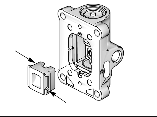
7. Install the spring (111◆). Lubricate and install the
air valve cup (112◆). Align the small round magnet
with the air inlet.
8. Install the valve plate (105◆). Tighten the screws
(109†◆)toholditinplace.
Replace Pilot Valves
1. Stop the pump at the middle of its stroke. Follow
Pressure Relief Procedure, page 8.
2. Disconnect the air line to the motor.
3. See Remove the Shroud, page 8.
4. Use a 10 mm socket wrench to remove the old pilot
valves (19) from the top and bottom covers.
5. Lubricate and install the new pilot valves (19).
Torque to 95-105 in-lb (11-12 N•m).
FIG. 6. Air valve cup installation
Magnet
112◆
ti12752a
Repair
12 3A1211M
Repair Air Motor
NOTE: Air Motor Seal Kits are available. See page 17
for the correct kit for your motor. Parts included in the kit
are marked with an asterisk (*). For best results, use all
the parts in the kit.
Preliminary Steps
1. Stop the pump at the middle of its stroke. Follow
Pressure Relief Procedure, page 8.
2. Disconnect air lines.
3. See Remove the Shroud, page 8.
Disassemble the Air Motor
1. Remove the tie rod nuts, tie rods, tie rod plate, and
bottom shroud.
2. Use a 10 mm socket wrench to remove four screws
(18). Remove the air valve (17) and gasket (16*◆).
3. Remove four screws (18) and remove the manifold
(15*) and gasket (14*).
4. Use a 10 mm socket wrench to remove the pilot
valves (19) from the top and bottom cover.
5. Remove the adapter (31) and o-ring (32) from cen-
ter of top cover (13).
6. Remove the tie bolts (10).
7. Remove the top cover. Remove the o-ring (9*).
8. Remove the cylinder (11).
9. Slide the piston assembly (5) straight up off the bot-
tom cover.
10. Remove o-ring (8*) from around the piston.
11. Remove retaining ring (4*), u-cup seals (3*, 33*),
and o-ring (9*) from the bottom cover.
Reassemble the Air Motor
NOTE: Use NLGI No 1, bentone-based grease for lubri-
cant. Exception: Use appropriate sanitary lubricant for
the center grommet in the bottom shroud.
NOTE: For easier reassembly, start with the top cover
(13) turned over on the workbench and assemble the air
motor upside-down.
1. Lubricate and install the o-ring (9*) on the top cover
(13).
2. 24G787 only: Install the upper bumper (29) on the
top cover (13).
3. Lubricate the inside of the cylinder (11). Lower the
cylinder (11) onto the top cover (13).
4. Lubricate and install the o-ring (8*) around the pis-
ton (5).
5. Slide the piston assembly (5) down into the cylinder
(11). Be sure the o-ring (9*) stays in place.
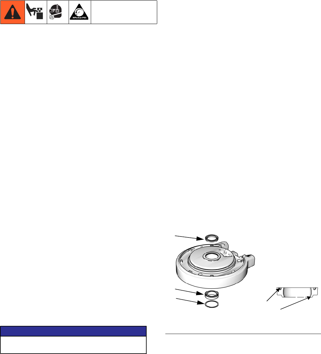
6. See FIG. 7. Lubricate and install new u-cup seal with
flange (33*) in the bottom of the bearing in the bot-
tom cover (1). The u-cup must face up and the
flange must face down. Lubricate and install new
u-cup seal (3*) in the top of the bearing. Lips must
face up. Install retaining ring (4*).
7. Lubricate and install the o-ring (9*) on the bottom
cover (1).
8. 24G787, 24G786, and 24W754 only: Install the pis-
ton bumper (28) on the bottom cover (1).
NOTICE
To prevent damage, do not attempt to take apart the
piston assembly (5).
FIG. 7. Air motor u-cup installation
3*
33*
ti12755a
U-cup faces up.
Flange faces down.
Lips face up
4*
Repair
3A1211M 13
9. Carefully place the bottom cover (1) on the cylinder
(11), sliding the rod through the bearing. The mani-
fold surfaces of the top and bottom covers must
align.
10. Install the tie bolts (10) hand tight.
11. Install two gaskets (14*) on the manifold (15). Install
the manifold (15). Torque bolts to 95-105 in-lb
(10.7-11.9 N•m).
12. Align the air valve gasket (16*◆) on the manifold,
then attach the air valve.
13. Tighten the tie bolts (10) halfway. Work in a criss-
cross pattern. Continue tightening the bolts in pat-
tern to the torque specified in the following table.
14. Lubricate and install pilot valves (19) in top and bot-
tom cover. Torque to 95-105 in-lb (11-12 N•m).
15. Install the adapter (31) and o-ring (32) in the center
of the top cover (13). Lubricate or apply sealant to
the o-ring as specified in the following table.
Attach the Shroud
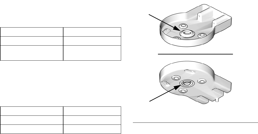
1. Inspect the grommets on the top and bottom
shrouds. Order Kit 16G628 (for 3.5 in. air motors) or
Kit 16G385 (for 6.0 in. or 7.5 in. air motors).
NOTE: The piston rod grommet (21a) must be installed
with the flat side down, as shown. The grommet will be
flush with the shroud when properly installed. It will not
remain in place if installed upside down. The other two
grommets are reversible.
2. If bottom shroud (47) has been removed, slide it up
onto the tie rods (10). Tighten the screws (48).
3. Lower the top shroud (46) over the air motor.
4. Grease and install the o-ring (39), hand screw (40),
and lift ring (41), hand tight.
5. Install the air inlet (43) and exhaust (42) fittings
tightly with a wrench.
Air Motor Torque
24G785 11-13 ft-lb (15-18 N•m)
24G786, 24G787, 24R491,
24R015, and 24W754
25-30 ft-lb (34-40 N•m)
Air Motor O-Ring
24G785, 24G786, 24G787 PTFE; apply sealant.
24R491, 24R015, 24W754 Buna-N; apply lubricant.
FIG. 8. Center Grommet Installation
ti12755a
21a
21a
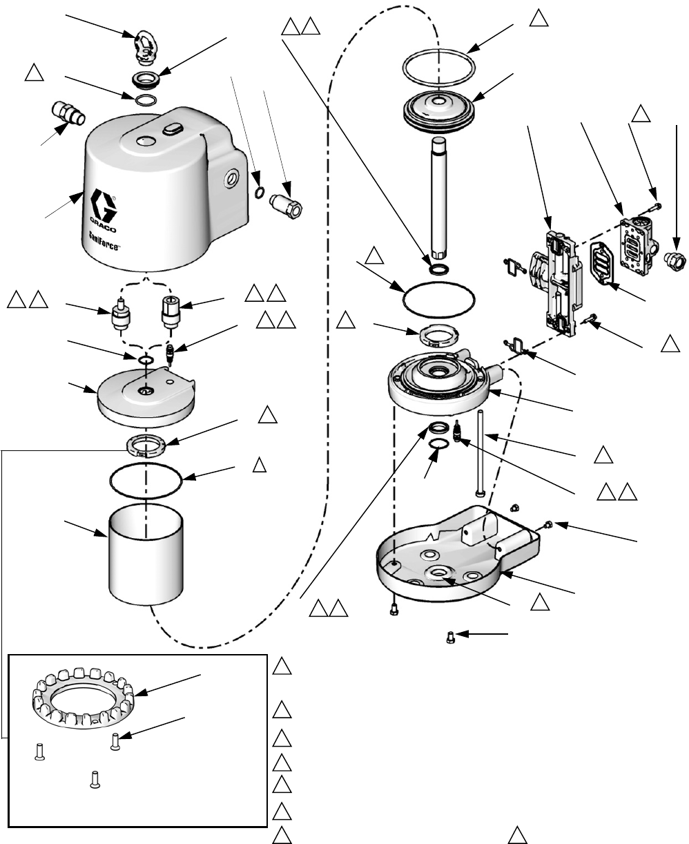
Parts
14 3A1211M
Parts
Air Motor Kit, plus Lift Ring, Fittings, Shrouds, and Fasteners
19
13
29
11
17
14*
9*
9*
33*
3* 8*
5
15 18
19
10
16*
◆
2
2
2
2
2
2
2
Apply NLGI No. 1, bentone-based grease.
1
32
ti116225b
28
1
2
31
1
ti16232a
39
2
40
41
3
U-cup faces up. Flange (bottom seal only) faces down.
See FIG. 7, page 12.
3
3
18
42
43
46
48
47
Upper Bumper - used
only on air motor
model 24G787 and
24R015.
29
30
4
Torque to 95-105 in-lb (11-12 N•m).
4
4
4
4
48
44
45
4*
50
5
5
Apply appropriate sanitary lubricant.
Torque varies by motor size: Model 24G785: 11-13 ft-lb (15-18 N
•m)
Models 24G786, 24G787, 24R015, 24R491: 25-30 ft-lb
(34-40 N•m)
31
6
7
Torque to 30-35 in-lb (41-47 N•m).
8
Press to snap fit.
7
6
7
6
8
8
Apply pipe sealant (Models 24R015, 24R491 and 24W754)
or lubricant (Models 24G785, 24G786, and 24G787).

Parts
3A1211M 15
Air Motor Parts — All Models
(See page 16 for Shroud Kits, Fittings, and Fasteners, sold separately.)
Ref. Description Qty
Model
24G785
Model
24G786
Model
24R491
Model
24G787
Model
24R015
Model
24W754
1 COVER, lower, assembly; includes
Refs. 3, 4, 9, 12, 19, 28, and 33
124A545 24A549 24A553 24A549
3* U-CUP 2 Not sold separately. See Air Motor Seal Kit (page 17) or
Lower Cover Assembly (Ref. 1, this table)
4* RETAINING RING 2 Not sold separately. See Air Motor Seal Kit (page 17) or
Lower Cover Assembly (Ref. 1, this table)
5 PISTON/ROD, assembly; includes Ref.
8
116G510 16G513 16G515 16G513
8* O-RING, piston 1 Not sold separately. See Air Motor Seal Kit (page 17) or
Piston Assembly (Ref. 5, this table)
9* O-RING, cover 2 Not sold separately. See Air Motor Seal Kit (page 17) or
Lower Cover Assembly (Ref. 1, this table)
10 BOLT, tie, hex head 3
4
6
15M313
-----
-----
-----
15M315
-----
-----
-----
15M315
15M315
11 CYLINDER, motor 1 15X783 16A517 16A516 24P936 16A517
12 SCREW, ground 1 116343 116343 116343 116343
13‡ COVER, upper, assembly, includes
Refs. 9, 19, 29, 30, 31, 32
116G516 16G517 16G518 16G517
14* GASKET, manifold 2 Not sold separately. See Air Motor Seal Kit (page 17) or
Manifold Assembly (Ref. 15, this table)
15 MANIFOLD, assembly, includes Refs.
14, 16, and 18 (qty. 4)
116G519 16G520 16G521 16G520
16*◆GASKET, air valve 1 Not sold separately. See Air Motor Seal Kit (page 17), Air Valve
Repair Kit (page 18), or Manifold Assembly (Ref. 15, this table)
17 VALVE, air, assembly; includes Refs. 16
and 18 (qty. 4)
124A352 24A352 24A352 24X156 24X156
18 SCREW, M6 x 25 8 Not sold separately. See Manifold Assembly (Ref. 15, this table) or
Air Valve Assembly (Ref. 17, this table)
19 VALVE, pilot 2 24A366 24A366 24A366 24A366
28 BUMPER KIT
Lower bumper only
Lower bumper, upper bumper, and
screws (qty. 3)
1
24A914
24A915
24A914
29 BUMPER, upper 1 Not sold separately.
See Bumper Kit (Ref.
28, this table)
30 SCREW, M5, flat head 3
Continued on next page.
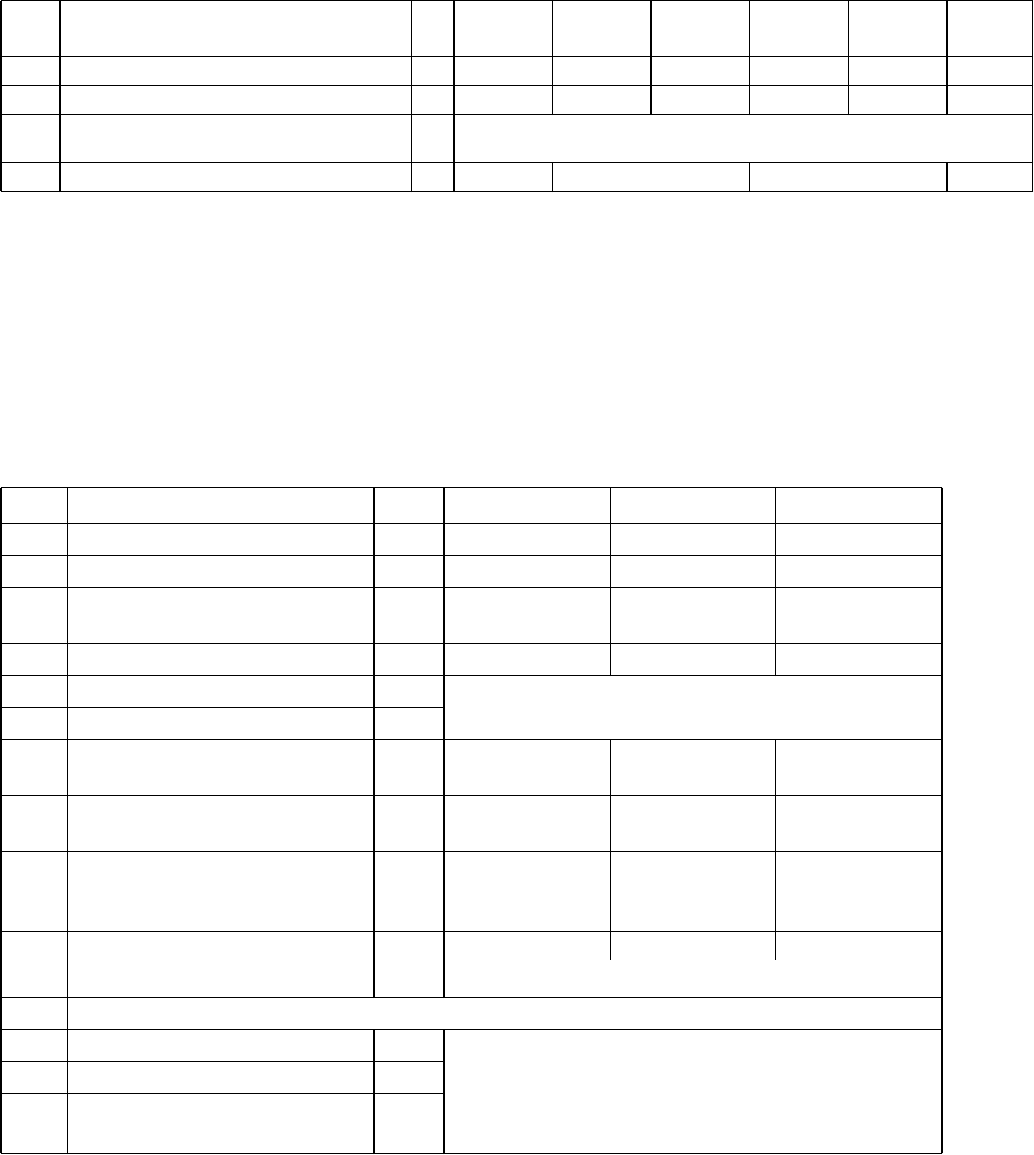
Parts
16 3A1211M
* Included in Air Motor Seal Kit. See page 17.
◆Included in Air Valve Repair Kit. See page 18.
‡ The upper cover assembly includes two adapter
o-rings. See Ref. 32 for the correct o-ring to use for
your motor.
▲Replacement Warning labels, signs, tags, and cards
are available at no cost.
Shroud Kits, Fittings, and Fasteners*
(See page 15 for Air Motor parts.)
* For ordering flexibility, Refs. 39-50 are not included when Air Motor Model 24G785, 24G786, 24G787, or 24R491
is purchased. These parts are included when Air Motor Kit with Shroud 24J760, 24J764, or 24J765 is purchased,
or when the air motor is purchased as part of a SaniForce Pump Package.
** For qty. 3 of the piston rod grommet, order Kit 16H925 for the 3.5 in. air motor or Kit 16G384 for the 6.0 in. or
7.5 in. air motor.
31 ADAPTER; includes Ref. 32 1 16T537 16T537 16V087 16T537 16G523 16G523
32 O-RING, for adapter 1 110636 110636 110782 110636 110782 110782
33 SEAL, u-cup with flange 1 Not sold separately. See Air Motor Seal Kit (page 17) or
Lower Cover Assembly (Ref. 1, this table)
35▲LABEL, warning (not shown) 280574 280574 280574 280574
Ref. Description Qty
Model
24G785
Model
24G786
Model
24R491
Model
24G787
Model
24R015
Model
24W754
Ref. Description Qty Model 24G785 Model 24G786 Model 24G787
39 O-RING 1 165053 165053 165053
40 HAND NUT 1 16C306 16C306 16C306
41 LIFT RING (not included with air
motors used on rams)
1 16C009 16C009 16C009
42 FITTING, exhaust 1 16C946 16C946 16C946
43 FITTING, air inlet 1 Not sold separately.
Order Air Inlet Fitting Kit 24G862.
44 O-RING, air inlet 1
45 FITTING, air inlet (normally
remains attached to shroud)
1 16G084 16G084 16G084
46 UPPER SHROUD KIT; includes
grommets (Ref. 50)
1 16G464 16G381 16G380
47 LOWER SHROUD KIT, includes
fasteners (Ref. 48) and grommets
(Ref. 50)
1 16G465 16G383 16G382
48 SCREW, cap; M8 x 1.25, sst 4 118134 118134 118134
Order Shroud Fastener Kit 16G432 for quantity of 4
50 GROMMET
50a** Air motor piston rod 1 Not sold separately.
Order Grommet Kit 16G628 (3.5 in. air motor) or
Grommet Kit 16G385 (6.0 in. or 7.5 in. air motor).
Grommets also come with Upper Shroud Kit (Ref. 46)
and Lower Shroud Kit (Ref. 47)
50b Air fitting 2
50c Tie rod 3
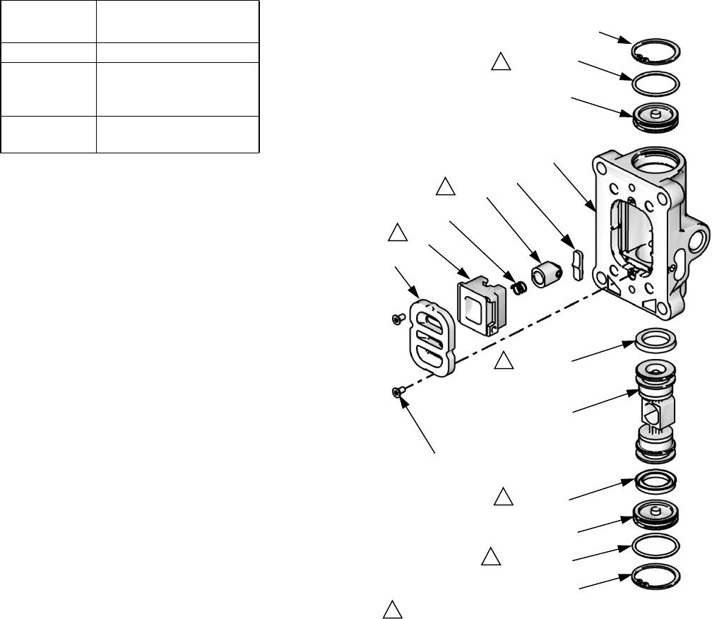
Parts
3A1211M 17
Air Motor Seal Kits Model 24A352 Air Valve Parts
Air Motor
Model Air Motor Seal Kit
24G785 16G524
24G786,
24R491, or
24W754
24A547
24G787 or
24R015
24A551
110◆✠
107✠
107✠
109†◆
105◆
112◆
111◆
103◆
102◆
ti11840a
101
104◆
110◆✠
1
1
1
1
1
1
Apply lubricant.
106†✠◆
106†✠◆
108†◆
108
†◆
1

Parts
18 3A1211M
Air Valve Kits
NOTE: Air valve parts are not sold individually. The table below shows possible kit options for each part.
† Included in Air Valve Seal Kit 24A536.
◆Included in Air Valve Repair Kit 24A538.
✠Included in Air Valve End Cap Kit 24A361.
Ref. Description Qty.
Air Valve
Repair Kit
24A538
Air Valve
Seal Kit
24A536
Air Valve
End Cap Kit
24A361 Other
101 HOUSING 1
102◆AIR VALVE PISTON 1✔
103◆DETENT PISTON
ASSEMBLY
1✔
104◆DETENT CAM 1✔
105◆PLATE, air valve 1✔
106†✠◆ O-RING 2✔✔ ✔
107✠CAP 2✔
108†◆U-CUP 2✔✔
109†◆SCREW 2✔✔ Screws Kit 24A359
(pack of 10)
110◆✠ SNAP RING 2✔✔
111◆DETENT SPRING 1✔
112◆CUP 1✔
18 SCREW, M6 x 25 4 See Manifold Assembly (Ref. 15,
Air Motor Kit Parts table) or
Air Valve Assembly (Ref. 17, Air
Motor Kit Parts table)
16*†◆AIR VALVE GASKET 1✔✔ See Air Motor Seal Kit (page 17)
or
Manifold Assembly (Ref. 15, Air
Motor Kit Parts table) or
Air Valve Assembly (Ref. 17, Air
Motor Kit Parts table)
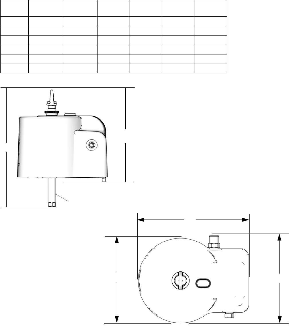
Dimensions
3A1211M 19
Dimensions
Air Motor
Model
A
inch (mm)
B
inch (mm)
C
inch (mm)
D
inch (mm)
E
inch (mm)
Weight
lb (kg)
24G785 13.7 (348) 16.3 (414) 10.0 (254) 7.7 (196) 9.2 (234) 12.0 (5.4)
24G786 14.5 (368) 18.8 (478) 14.2 (361) 10.9 (277) 11.0 (279) 26.0 (11.8)
24G787 14.5 (368) 18.8 (478) 14.2 (361) 10.9 (277) 11.0 (279) 31.0 (14.1)
24R491 17.8 (452) 22.1 (561) 14.2 (361) 10.9 (277) 11.0 (279) 26.0 (11.8)
24R015 14.5 (368) 18.8 (478) 14.2 (361) 10.9 (277) 11.0 (279) 26.0 (11.8)
24W754 14.5 (368) 18.8 (478) 14.2 (361) 10.9 (277) 11.0 (279) 26.0 (11.8)
B
A
C
DE
ti16223a
ti16224a
Midstroke

Dimensions
20 3A1211M
Technical Data
3A1211M 21
Technical Data
* Sound power at 70 psi (0.48 MPa, 4.8 bar), 20 cpm. Sound power measured per ISO-9614-2.
** Sound pressure was tested 3.28 feet (1 m) from equipment.
Maximum air inlet pressure ....................... 100psi(0.7MPa,7.0bar)
Stroke length .................................. 4.75in.
Airinletsize ................................... 1/2in.npt(f)
Air exhaust .................................... 3/4in.npt(m)
Maximum motor speed...........................
(Do not exceed maximum recommended speed of fluid
pump, to prevent premature pump wear.)
60 cycles per minute
Sound data
24G785
Sound power* ............................. 78.5dBA
Sound pressure** .......................... 71.6dBA
24G786, 24R491, or 24W754
Sound power* ............................. 77.5dBA
Sound pressure** .......................... 70.7dBA
24G787 or 24R015
Sound power* ............................. 77.2dBA
Sound pressure** .......................... 70.5dBA

All written and visual data contained in this document reflects the latest product information available at the time of publication.
Graco reserves the right to make changes at any time without notice.
2ULJLQDOLQVWUXFWLRQV This manual contains English. MM 3A1211
Graco Headquarters: Minneapolis
International Offices: Belgium, China, Japan, Korea
GRACO INC. AND SUBSIDIARIES • P.O. BOX 1441 • MINNEAPOLIS MN 55440-1441 • USA
Copyright 2010, Graco Inc. All Graco manufacturing locations are registered to ISO 9001.
www.graco.com
Revision M, May 2015
Graco Standard Warranty
Graco warrants all equipment referenced in this document which is manufactured by Graco and bearing its name to be free from defects in
material and workmanship on the date of sale to the original purchaser for use. With the exception of any special, extended, or limited warranty
published by Graco, Graco will, for a period of twelve months from the date of sale, repair or replace any part of the equipment determined by
Graco to be defective. This warranty applies only when the equipment is installed, operated and maintained in accordance with Graco’s written
recommendations.
This warranty does not cover, and Graco shall not be liable for general wear and tear, or any malfunction, damage or wear caused by faulty
installation, misapplication, abrasion, corrosion, inadequate or improper maintenance, negligence, accident, tampering, or substitution of
non-Graco component parts. Nor shall Graco be liable for malfunction, damage or wear caused by the incompatibility of Graco equipment with
structures, accessories, equipment or materials not supplied by Graco, or the improper design, manufacture, installation, operation or
maintenance of structures, accessories, equipment or materials not supplied by Graco.
This warranty is conditioned upon the prepaid return of the equipment claimed to be defective to an authorized Graco distributor for verification of
the claimed defect. If the claimed defect is verified, Graco will repair or replace free of charge any defective parts. The equipment will be returned
to the original purchaser transportation prepaid. If inspection of the equipment does not disclose any defect in material or workmanship, repairs will
be made at a reasonable charge, which charges may include the costs of parts, labor, and transportation.
THIS WARRANTY IS EXCLUSIVE, AND IS IN LIEU OF ANY OTHER WARRANTIES, EXPRESS OR IMPLIED, INCLUDING BUT NOT LIMITED
TO WARRANTY OF MERCHANTABILITY OR WARRANTY OF FITNESS FOR A PARTICULAR PURPOSE.
Graco’s sole obligation and buyer’s sole remedy for any breach of warranty shall be as set forth above. The buyer agrees that no other remedy
(including, but not limited to, incidental or consequential damages for lost profits, lost sales, injury to person or property, or any other incidental or
consequential loss) shall be available. Any action for breach of warranty must be brought within two (2) years of the date of sale.
GRACO MAKES NO WARRANTY, AND DISCLAIMS ALL IMPLIED WARRANTIES OF MERCHANTABILITY AND FITNESS FOR A
PARTICULAR PURPOSE, IN CONNECTION WITH ACCESSORIES, EQUIPMENT, MATERIALS OR COMPONENTS SOLD BUT NOT
MANUFACTURED BY GRACO. These items sold, but not manufactured by Graco (such as electric motors, switches, hose, etc.), are subject to
the warranty, if any, of their manufacturer. Graco will provide purchaser with reasonable assistance in making any claim for breach of these
warranties.
In no event will Graco be liable for indirect, incidental, special or consequential damages resulting from Graco supplying equipment hereunder, or
the furnishing, performance, or use of any products or other goods sold hereto, whether due to a breach of contract, breach of warranty, the
negligence of Graco, or otherwise.
FOR GRACO CANADA CUSTOMERS
The Parties acknowledge that they have required that the present document, as well as all documents, notices and legal proceedings entered into,
given or instituted pursuant hereto or relating directly or indirectly hereto, be drawn up in English. Les parties reconnaissent avoir convenu que la
rédaction du présente document sera en Anglais, ainsi que tous documents, avis et procédures judiciaires exécutés, donnés ou intentés, à la suite
de ou en rapport, directement ou indirectement, avec les procédures concernées.
Graco Information
For the latest information about Graco products, visit www.graco.com.
For patent information, see www.graco.com/patents.
TO PLACE AN ORDER, contact your Graco distributor or call to identify the nearest distributor.
Phone: 612-623-6921 or Toll Free: 1-800-328-0211 Fax: 612-378-3505
