Graco 3A2527E 3A2527E, 24P822 E Flo DC Control Module Kit, Instructions/Parts, English User Manual To The Bbc49eec 16cb 4f01 B701 38cf9d123b7d
User Manual: Graco 3A2527E to the manual
Open the PDF directly: View PDF ![]() .
.
Page Count: 40
Instructions - Parts
24P822 E-Flo® DC Control
Module Kit 3A2527E
EN
User Interface for E-Flo® DC Pumps with an Advanced Motor.
For professional use only.
Important Safety Instructions
Read all warnings and instructions in this manual, the supplied
ADCM manual, and the E-Flo DC manuals.
Save these instructions.
See the separate manual (supplied)
for complete warnings and approvals
information about the 24L097 Advanced
Display Control Module (ADCM).
PROVEN QUALITY. LEADING TECHNOLOGY.
Contents
Control Module...................................................3
Installation.......................................................... 3
Install the Control Module ............................. 3
Install Optional Accessory Kits ...................... 4
Cable Connection ........................................ 5
Operation........................................................... 6
Module Screens........................................... 6
Module Keys................................................ 6
Icons...........................................................8
Screen Navigation and Editing ...................... 9
Initial Setup ................................................. 9
Screen Map........................................................ 10
Run Screens ......................................................12
Run Screen 1 .............................................. 12
Run Screen 2 .............................................. 13
Run Screen 3 .............................................. 13
Run Screen 4 .............................................. 14
Run Screens 5–8 ......................................... 14
Setup Screens.................................................... 16
Setup Screen 1............................................ 16
Setup Screen 2............................................ 18
Setup Screen 3............................................ 19
Setup Screen 4............................................ 20
Setup Screen 5............................................ 22
Setup Screen 6............................................ 23
Setup Screen 7............................................ 23
Setup Screens 8 and 9 ................................. 24
Setup Screens 10 and 11 ............................. 25
Setup Screen 12.......................................... 26
Setup Screen 13.......................................... 27
Setup Screen 14.......................................... 28
Setup Screen 15.......................................... 29
Error Code Troubleshooting ................................ 30
Parts.................................................................. 32
24P822 Control Module Kit ........................... 32
Appendix A - Modbus Variable Map ..................... 34
Appendix B. Pump Control from a PLC ................ 38
Graco Standard Warranty.................................... 40
23A2527E
Control Module
Control Module
The Control Module provides the interface for users
to enter selections and view information related to
setup and operation.
The screen backlight is factory set to remain on,
even without screen activity. See Setup Screen 4
to set the backlight timer to your preference. Press
any key to restore.
Keys are used to input numerical data, enter setup
screens, navigate within a screen, scroll through
screens, and select setup values.
Installation
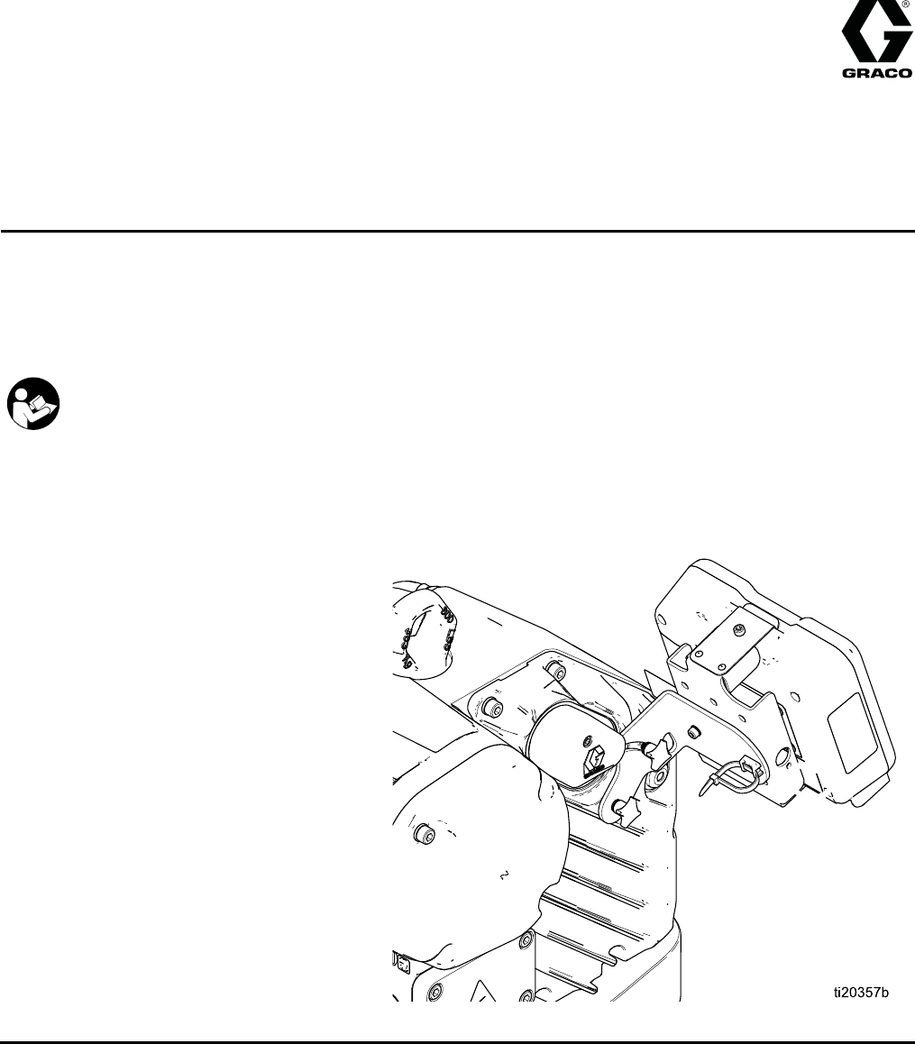
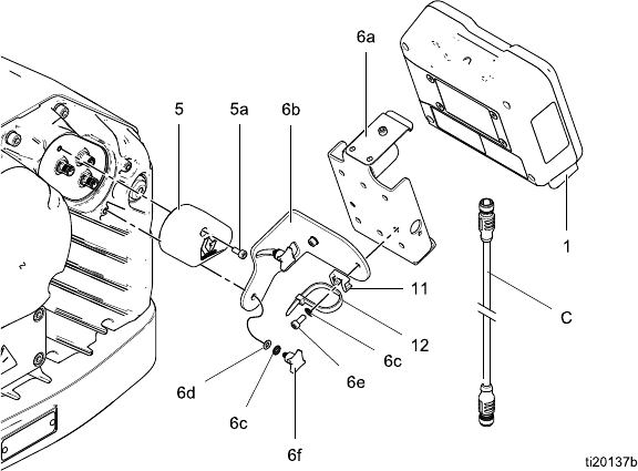
Install the Control Module
1. Shut off and lock out power to the motor.
2. Install the jumper connector (5) over the top two
terminals of the motor, using the screw (5a).
NOTE: To connect up to 8 motors together, see
Appendix A in the E-Flo DC Motor Manual, where
the control module is the referenced intrinsically
safe (IS) apparatus.
3. Assemble the bracket kit (6a-6f) and the holder
and tie (11, 12) as shown.
4. Install the module (1) in the bracket (6a), making
sure the tabs at the bottom of the bracket engage
the slots in the module, and the lip at the top of
the bracket holds the module securely in place.
5. Connect the accessory cable (C), using the
tie (12) as a strain relief as shown. See
Cable Connection, page 5 .
6. Restore power to the motor.
Figure 1 Install the Control Module
3A2527E 3
Installation
Install Optional Accessory Kits
Optional accessory kits are available for purchase
separately, including a pressure transducer kit (PN
24R050 for 4–ball pumps; PN 24Y245 for 2–ball
pumps), a start/stop switch kit (PN 16U729), and a
controller kit (24V001 ) for a back pressure regulator.
Pressure Transducer Kit
1. To measure fluid pressure, install the pressure
transducer in the fluid line with a tee fitting.
Option Description
Closed Loop Control
Enabled
If closed loop control
is enabled on Setup
Screen 8 (transducer
1) or Setup Screen 9
(transducer 2), install
the transducer near the
pump outlet, not near
the end of the circulation
line.
Closed Loop Control
Not Enabled
Install the transducer
where needed.
2. Connect the transducer cable to Port 7
(transducer 1) or Port 10 (transducer 2) on the
control module.
Start/Stop Switch Kit
1. Mount the switch near the control module, using
the bracket provided.
2. Connect the switch cable to Port 4 on the control
module.
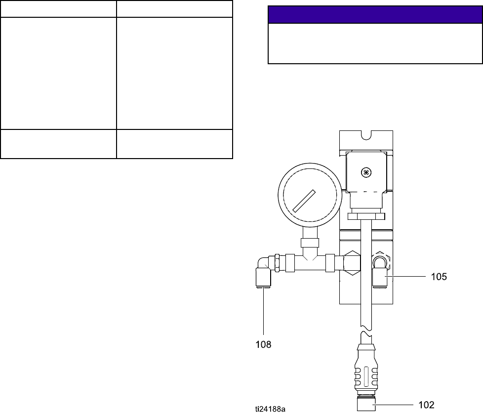
BPR Controller
The BPR (back pressure regulator) controller enables
theusertocontrolthebackfluidpressurefromthe
control module.
1. Mount the BPR controller using the bracket
provided.
2. Connect a supply air line to the BPR controller
air inlet (105).
NOTICE
To prevent equipment damage, always apply
air pressure to the BPR controller before
applying power to the system.
3. Connect an air line from the BPR controller air
output (108) to the BPR.
4. Connect the BPR controller input cable (102) to
Port 8 on the control module.
43A2527E
Installation
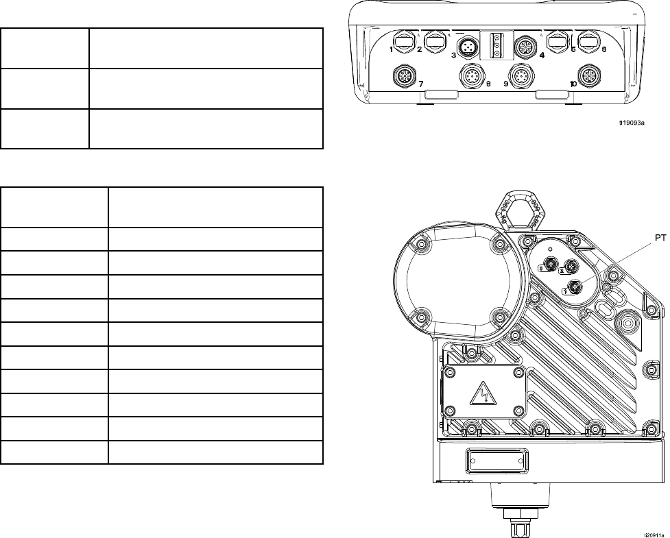
Cable Connection
Order an accessory cable (C) from Table 1. Connect the cable to Port 3 on the bottom of the control module
(see Fig. 2). Connect the other end to the power terminal (PT) on the motor (see Fig. 3). Connect other
cables as described in Table 2.
Table 1 CAN Cables
Cable Part
No.
Description
16P911 Intrinsically safe CAN cable, female
x female, 3 ft (1 m)
16P912 Intrinsically safe CAN cable, female
x female, 25 ft (8 m)
Table 2 ADCM Cable Connections
ADCM Port
Number
Connector Purpose
1Fiber Optic RX - to PLC
2Fiber Optic TX - to PLC
3Power and CAN communication
4Start/stop input
5Fiber Optic RX - to next ADCM
6Fiber Optic TX - tos next ADCM
7Pressure transducer 1
8 BPR control 4-20mA output
9 Not used
10 Pressure transducer 2
Figure 2 ADCM Connectors
Figure 3 Motor Power Terminal
3A2527E 5
Operation
Operation
Module Screens
The Control Module has two sets of screens:
Run and Setup. For detailed information see
Run Screens, page 12, and Setup Screens, page 16.
Press to toggle between the Run screens and
the Setup screens.
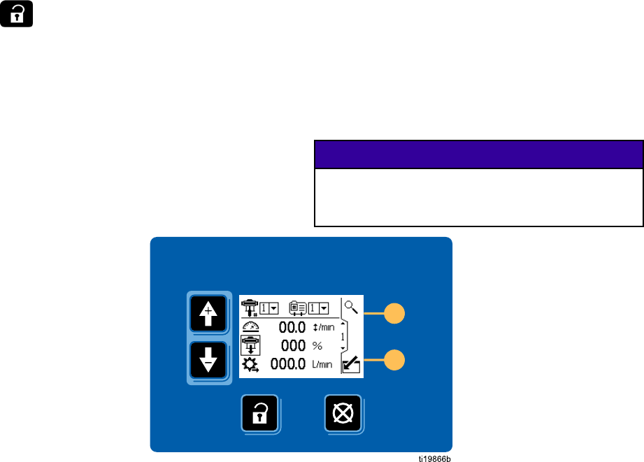
Module Keys
Fig. 4 is a view of the control module display and
keys. Table 2 explains the function of the membrane
keys on the control module. As you move through
the screens, you will notice that most information
is communicated using icons rather than words
to simplify global communication. The detailed
screen descriptions in Run Screens, page 12,and
Setup Screens, page 16, explain what each icon
represents. The two softkeys are membrane buttons
whose function correlates with the screen content to
the immediate left of the button.
NOTICE
To prevent damage to the softkey buttons, do not
press the buttons with sharp objects such as pens,
plastic cards, or fingernails.
Figure 4 Control Module Keypad and Display
63A2527E
Operation
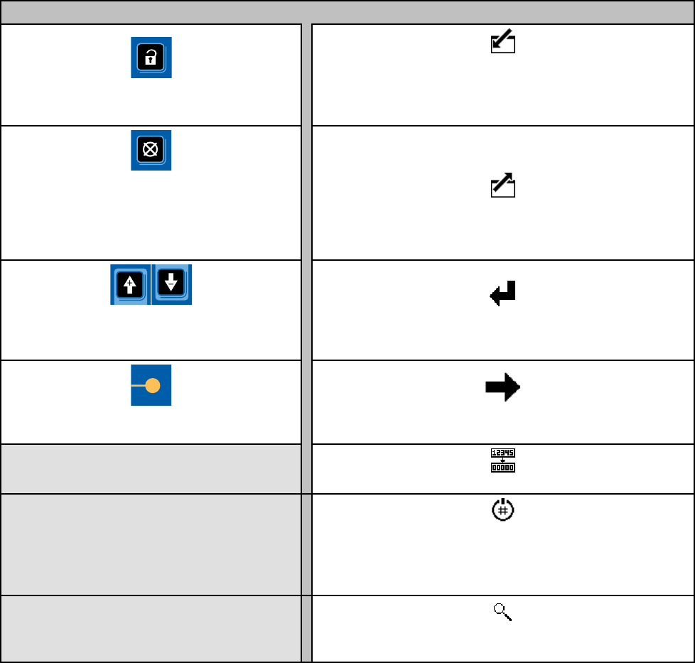
Table 3 Module Keys
Membrane Keys Softkeys
Press to toggle between Run screens
and Setup screens.
Enter Screen.
Highlight data that can be edited.
Also changes the function of the Up/Down
arrows so they move between data fields on
the screen, rather than between screens.
Error Reset:
Use to clear alarm after cause
has been fixed. When there is no alarm to
clear, this key will set the active pump’s
profile to Stop. Also used to cancel data
entered and return to original data.
Exit Screen.
Exit data editing.
Up/Down Arrows:
Use to move between
screens or fields on a screen, or to increment
or decrement the digits in a settable field.
Enter.
Press to activate a field for editing or to accept
the highlighted selection on a dropdown menu.
Softkeys:
Use varies by screen.
See columns at right.
Right.
Move to the right when editing number fields. Press
again to accept the entry when all digits are correct.
Reset.
Reset totalizer to zero.
Activate Profile.
This softkey is disabled by
default, and only appears if the “Profile Lock”
box is checked on Setup Screen 15, page 29.
Press to activate the profile just edited.
Search.
PressinRunScreen1tomakethe
active pump blink for identification.
3A2527E 7
Operation
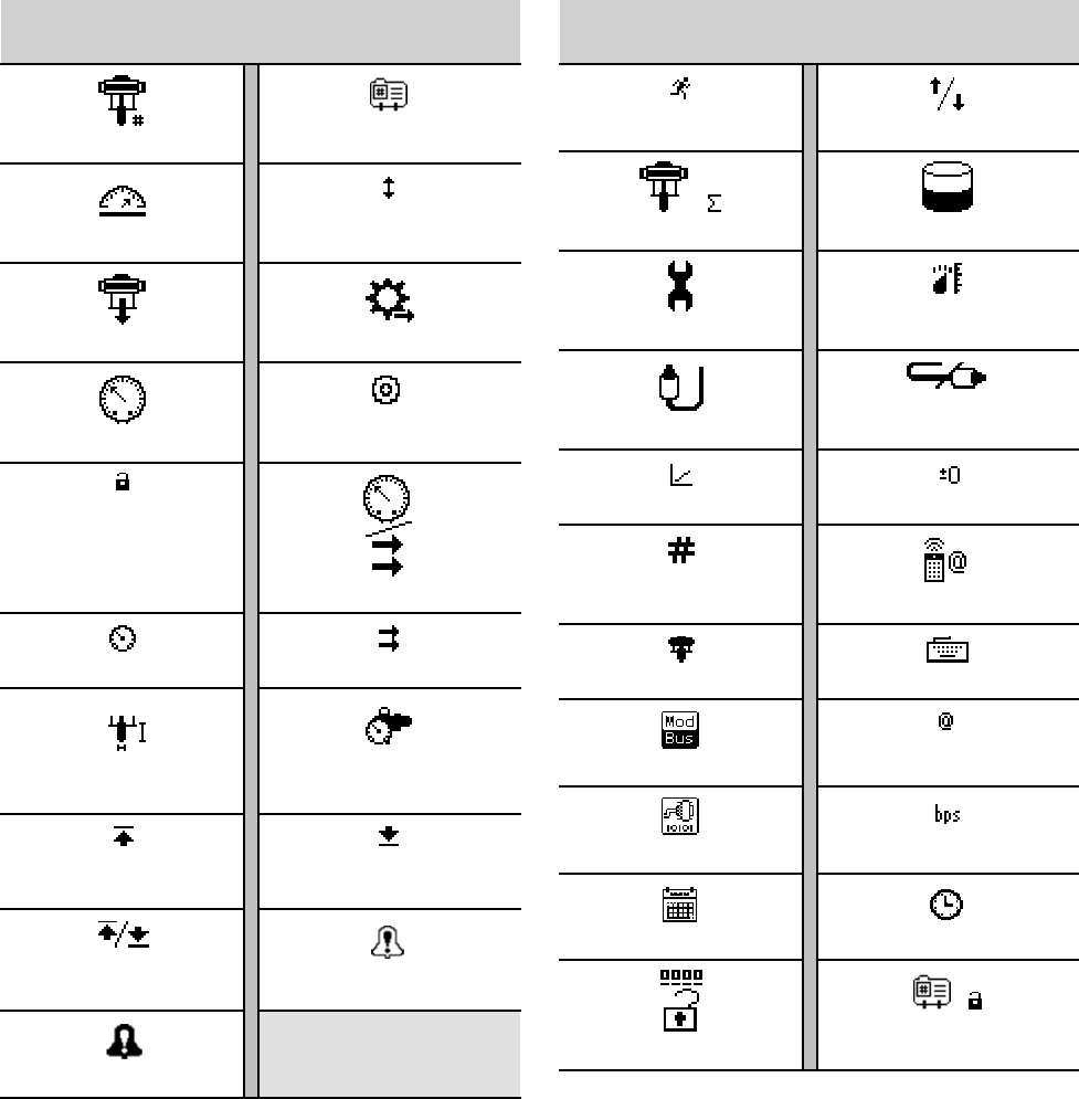
Icons
Asyoumovethr
ough the screens, you will notice that most information is communicated using icons rather
than words to simplify global communication. The detailed screen descriptions in RunScreens,page12, and
Setup Screens,page16, explain what each icon represents.
Screen Icons
Pump Number Profile Number
Speed
Cycles
Pump Pressure Flow Rate
Pressure Target
In Setup Mode
Mode Select
Pressure Mode Flow Mode
Lower Size Back Pressure
Regulator
Maximum
Limit
Minimum
Limit
Maximum and
Minimum Limits Deviation Enable
Alarm Enable
Screen Icons
Jog Mode Jog Up/Down
Cycles Total Volume
Maintenance Units
Transducer
Pressure Transducer Off
Calibration Scale Zero Offset
Serial Number
Control Location
Local Control PLC/Remote Control
Modbus Device Modbus Address
Serial Port Serial Baudrate
Calendar Clock
Password
Lock Profile
83A2527E
Operation
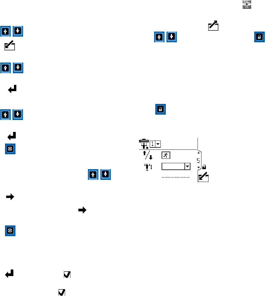
Screen Navigation and Editing
Refer to this section if you have questions about
screen navigation or about how to enter information
and make selections.
All Screens
1. Use to move between screens.
2. Press to enter a screen. The first data field
on the screen will highlight.
3. Use to highlight the data you wish to
change.
4. Press to edit.
Drop Down Field
1. Use to highlight the correct choice from
the dropdown menu.
2. Press to select.
3. Press to cancel.
Number Field
1. The first digit will be highlighted. Use
to change the number.
2. Press to move to the next digit.
3. When all digits are correct, press again to
accept.
4. Press to cancel.
Check Box Field
A check box field is used to enable or disable features
in the software.
1. Press to toggle between andanempty
box.
2. The feature is enabled if a is in the box.
Reset Field
The reset field is used for totalizers. Press to
reset the field to zero.
When all data is correct, press to exit the screen.
Then use to move to a new screen, or
to move between Setup screens and Run screens.
Initial Setup
NOTE: Before creating the pump profiles in Setup
Screens 1 through 4, you must set up the system
parameters in Setup Screens 5 through 15, as
follows.
1. Press to enter the Setup screens. Setup
Screen 1 will appear.
2. Scroll to Setup Screen 5.
3. See Setup Screen 5, page 22,andselectthe
lower used in your system.
4. Continue setting the system parameters
on Setup Screen 6, page 23 through
Setup Screen 15, page 29.
5. Scroll to Setup Screen 1. Establish
the profiles for each pump. See
Setup Screen 1, page 16 through
SetupScreen4,page20.
3A2527E 9
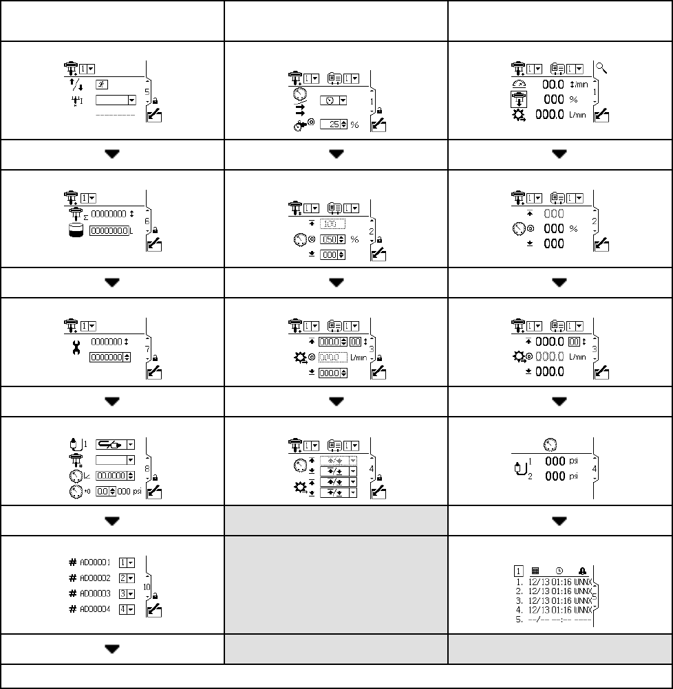
Screen Map
Screen Map
INITIAL SETUP
(Setup Screens 5–14)
SETUP AND EDIT PROFILES
(Setup Screens 1–4)
RUN
(Run Screens 1–8)
Setup Screen 5, page 22 Setup Screen 1, page 16 Run Screen 1, page 12
Setup Screen 6, page 23 Setup Screen 2, page 18 Run Screen2,page13
Setup Screen 7, page 23 Setup Screen 3, page 19 Run Screen 3, page 13
Setup Screens 8 and 9, page 24 Setup Screen 4, page 20 Run Screen 4, page 14
Setup Screens 10 and 11, page 25 Run Screens 5–8, page 14
CONTINUED ON THE NEXT PAGE.
10 3A2527E
Run Screens
Run Screens
The Run screens display current target values and
performance for a selected pump and profile. Any
alarms will display in the sidebar at the right of the
screen. Screens 5–8 display a log of the last 20
alarms for the active pump.
Information displayedontheRunscreens
corresponds to the Modbus Registers. See
Appendix A - Modbus Variable Map, page 34.
TheactivepumpandprofilemaybechangedinRun
Screens 1, 2, and 3.
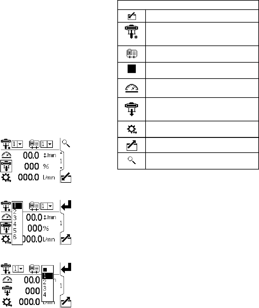
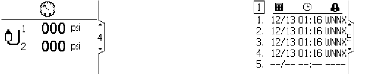
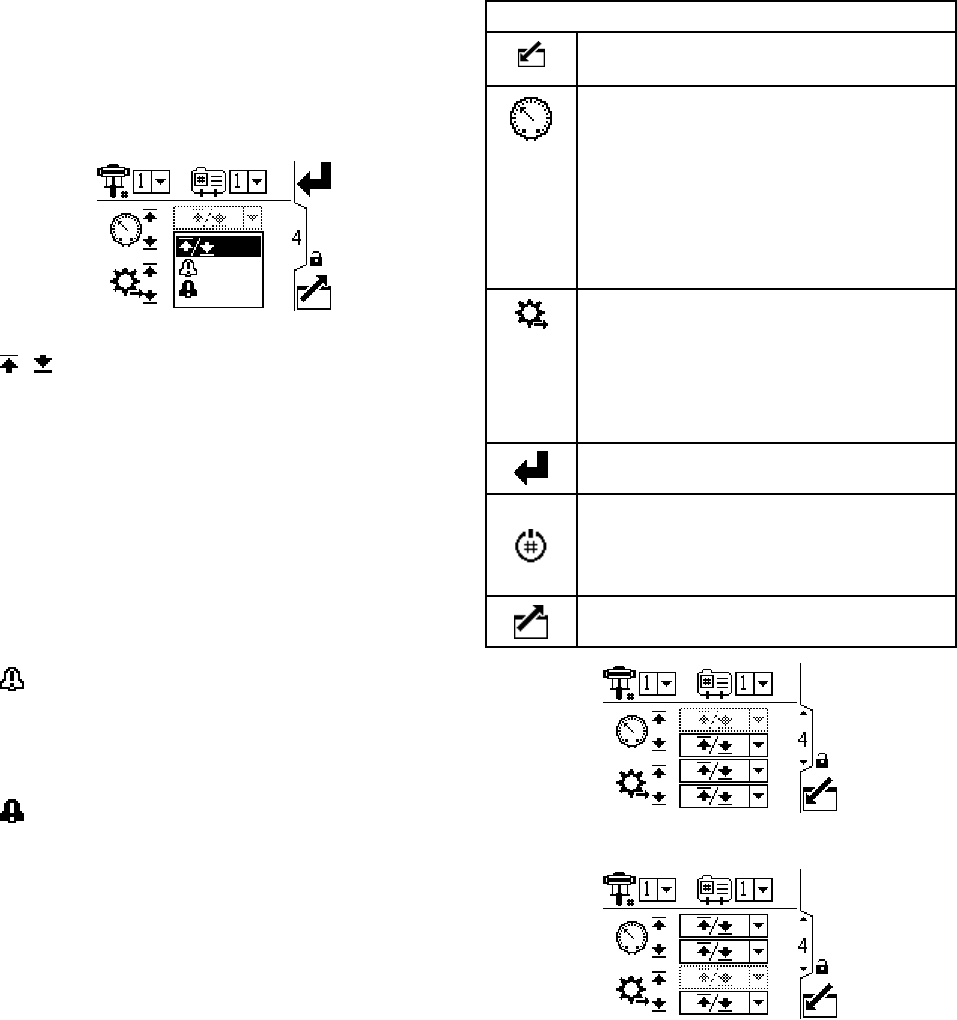
Run Screen 1
This screen displays information for a selected
pump and profile. A box around an icon indicates
which mode the active pump and profile is running
(pressure or flow).
Figure 5 Run Screen 1
Figure 6 Select a Pump
Figure 7 Select a Profile
RunScreen1Key
Enter the screen.
For systems with multiple pumps and
one display, select the desired pump (1
to 8), using the pull-down menu.
Select the desired profile (1 to 4), using
the pull-down menu.
Select from the profile drop-down menu
to stop the pump.
Displays current pump speed in cycles
per minute.
Displays current pump pressure as a
percentage. If a transducer is used, this
icon is replaced by the pressure icon.
Displays current flow rate, in units as
selected in Setup Screen 13, page 27.
Exit the screen.
Signals the active pump to blink code 9
for identification.
123A2527E
Run Screens
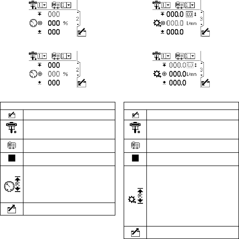
Run Screen 2
This screen displays pressure settings for the active
pump and profile.
NOTE: Some fields are grayed out, depending on
setup selections.
Figure 8 Run Screen 2, in Pressure Mode
Figure 9 Run Screen 2, in Flow Mode
Run Screen 2 Key
Enter the screen.
For systems with multiple pumps and
one display, select the desired pump (1
to 8), using the pull-down menu.
Select the desired profile (1 to 4), using
the pull-down menu.
Select from the profile drop-down menu
to stop the pump.
Displays pressure maximum (first data
field), target (second data field), and
minimum (third data field), as selected
in Setup Screen 2, page 18.See
Setup Screen 4, page 20 to set or
disable the pressure alarms.
Exit the screen.
Run Screen 3
This screen displays fluid flow settings for the active
pump and profile.
NOTE: Some fields are grayed out, depending on
setup selections.
Figure10 RunScreen3,inPressureMode
Figure 11 Run Screen 3, in Flow Mode
RunScreen3Key
Enter the screen.
For systems with multiple pumps and
one display, select the desired pump (1
to 8), using the pull-down menu.
Select the desired profile (1 to 4), using
the pull-down menu.
Select from the profile drop-down menu
to stop the pump.
The first line displays the maximum
flow rate and maximum cycle rate
(displayed as a cpm conversion of the
maximum flow setting). The second
line displays the target flow rate. The
third line displays the minimum flow
rate. See SetupScreen3,page19to
establish these settings. See
Setup Screen 4, page 20 to set or
disable the flow alarms.
Exit the screen.
3A2527E 13
Run Screens
Run Screen 4
This screen displays the current pressure readings of
transducers 1 and 2. Pressure can be displayed as
psi, bar, or MPa. See Setup Screen 13, page 27.
Figure 12 Run Screen 4
Run Screens 5–8
Run Screens 5–8 display a log of the last 20 alarms,
with date and time. The currently active pump is
displayed in a box at the top left of the screen.
Figure 13 Run Screens 5–8 (Screen 5 shown)
143A2527E


Setup Screens
Setup Screens
Use the Setup screens to set control
parameters for the motor. See
Screen Navigation and Editing, page 9 ,for
information on how to make selections and enter
data.
Inactive fields are grayed-out on a screen.
Information displayed on the Setup screens
corresponds to the Modbus Registers. See
Appendix A - Modbus Variable Map, page 34.
NOTE: Before setting up profiles on Setup Screens
1–4, do the initial setup on Setup Screens 5–15.
Screens 5–15 establish the configuration for your
system and affect the displayed data.
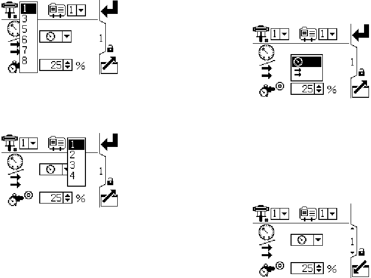
SetupScreen1
Use this screen to set the operating mode for a
selected pump and profile.
Figure 14 Setup Screen 1
SetupScreen1Key
Enter the screen.
Pump selection — See Step 1.
Profile selection — See Step 2.
Pressure mode or Flow mode — See
Step 3
Setting for Back Pressure Regulator —
SeeStep4.
Press to accept the selections.
This softkey is disabled by default, and
only appears if the “Profile Lock” box is
checked on Setup Screen 15, page 29.
Press to activate the profile just edited.
Exit the screen.
16 3A2527E
Setup Screens
1. For systems with multiple pumps and one
display, select the desired pump (1 to 8), using
the pull-down menu.
Figure 15 Select Pump Number
2. Select the desired profile (1 to 4), using the
pull-down menu.
Figure 16 Select Profile Number
3. Select the desired operating mode (pressure or
flow), using the pull-down menu.
•In pressure mode, the motor will adjust the
pump speed to maintain the fluid pressure
percentage set on Setup Screen 2. If the flow
limit is reached before the target pressure, the
unit will stop driving to the pressure (if set as
an alarm).
•In flow mode, the motor will maintain a
constant speed to maintain the target flow rate
set on Setup Screen 3, regardless of the fluid
pressure, up to the pump’s maximum working
pressure.
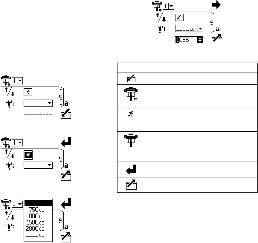
Figure 17 Select Mode (Pressure Mode Shown)
4. If the system is equipped with a back pressure
regulator (BPR), set the target air pressure to the
BPR from 0 to 100 percent (approximately 1 to
100 psi). Leave the field set to 000 for a system
with no BPR. See manual 332142 for information
on the BPR control kit.
Figure 18 Set Back Pressure Regulator
3A2527E 17
Setup Screens
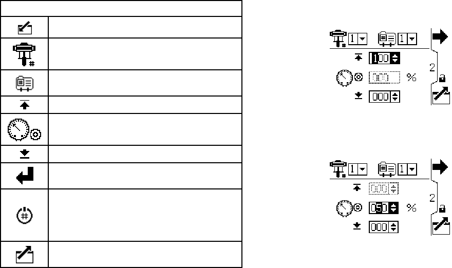
Setup Screen 2
Use this screen to set the maximum, target, and
minimum fluid pressure for a selected pump and
profile. In pressure mode, you will set a target fluid
pressure. In flow mode, you will set a maximum
fluid pressure. In either pressure or flow mode,
a minimum pressure may be set if desired. See
Setup Screen 4, page 20, to specify how the system
will respond if the pump begins to operate outside of
the set boundaries.
SetupScreen2Key
Enter the screen.
Pump selection — See Step 1.
Profile selection — See Step 2.
Fluid pressure maximum— See Step 3.
Fluid pressure target — See Step 4.
Fluid pressure minimum — See Step 5.
Press to accept the selections.
This softkey is disabled by default, and
only appears if the “Profile Lock” box is
checked on Setup Screen 15, page 29.
Press to activate the profile just edited.
Exit the screen.
1. For systems with multiple pumps and one
display, select the desired pump (1 to 8), using
the pull-down menu.
2. Select the desired profile (1 to 4), using the
pull-down menu.
3. In flow mode, set the desired maximum pump
fluid pressure, as a percentage of the maximum
pressure of your pump. NOTE: The motor will
not run if the profile does not have a maximum
pressure setting. This field is not used in
pressure mode.
4. In pressure mode, set the desired fluid pressure
target as a percentage of the maximum pressure
of your pump. This field is not used in flow mode.
NOTE: If closed loop pressure is enabled, the
target pressure will be displayed as a pressure
value rather than a percentage of maximum
pressure. See Setup Screens 8 and 9, page 24 to
enable closed loop pressure control.
5. If desired, set a minimum pump fluid pressure,
as a percentage of the maximum fluid pressure
of your pump.
18 3A2527E
Setup Screens
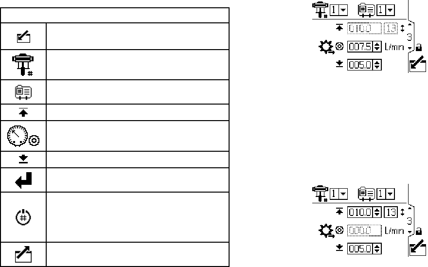
Setup Screen 3
Use this screen to set your flow rate settings for a
selected pump and profile. In pressure mode, you
will set a maximum flow rate. In flow mode, you
will set a target flow rate. In either pressure or flow
mode, a minimum flow rate may be set if desired.
SeeSetupScreen4tospecifyhowthesystemwill
respond if the pump begins to operate outside of the
set boundaries.
SetupScreen3Key
Enter the screen to set or change
preferences.
Pump selection — See Step 1.
Profile selection — See Step 2.
Flow rate maximum— See Step 3.
Flow ratetarget—SeeStep4.
Flow rate minimum — See Step 5.
Press to accept the selections.
This softkey is disabled by default, and
only appears if the “Profile Lock” box is
checked on Setup Screen 15, page 29.
Press to activate the profile just edited.
Exit data editing.
NOTE: With flow rate units of cc/min, the maximum
value that can be displayed is 9999. If the field
displays ####, the saved value is out of range. Go to
Setup Screen 13, page 27 and change the flow rate
to a larger unit. Return to this screen and reduce the
setting to a lower value that will be within the display’s
range, then reset the flow rate units to cc/min.
1. For systems with multiple pumps and one
display, select the desired pump (1 to 8), using
the pull-down menu.
2. Select the desired profile (1 to 4), using the
pull-down menu.
3. In flow mode, set a target flow rate. This field is
not used in pressure mode.
Figure 19 Flow Mode: Flow Rate Settings
4. In pressure mode, set the maximum flow rate.The
software will calculate the number of pump cycles
needed to achieve that flow rate. This field is not
used in flow mode.
NOTE: The motor will not run if the profile does
not have a maximum flow rate setting.
Figure 20 Pressure Mode: Flow Rate Settingss
5. If desired, set a minimum flow rate.
3A2527E 19
Setup Screens
Setup Screen 4
Use this screen to specify how the system will
respond if the pump begins to operate outside of
the pressure and flow settings established on Setup
Screen 2 and Setup Screen 3. The operating mode
(pressure or flow, set on Setup Screen 1) determines
which fields are active.
Figure 21 Alarm Preference Menu
•/Limit: The pump continues to run and issues
no alert.
– Maximum pressure set to Limit: The system
reduces the flow if necessary to prevent the
pressure from exceeding the limit.
– Maximum flow set to Limit: The system reduces
thepressureifnecessarytopreventtheflow
from exceeding the limit.
– Minimum pressure or flow set to Limit: The
system takes no action. Use this setting if no
minimum pressure or flow setting is desired.
•Deviation: The system alerts you to the
problem, but the pump may continue to run
past the maximum or minimum settings until the
system’s absolute pressure or flow boundaries are
reached.
•Alarm: The system alerts you to the alarm
cause and shuts down the pump.
SetupScreen4Key
Enter the screen to set or change
preferences.
Pressure Alarm Enable
Line 1 (Pressure Maximum): use
dropdown menu to set as Limit,
Deviation, or Alarm.
Line 2 (Pressure Minimum): use
dropdown menu to set as Limit,
Deviation, or Alarm.
Flow Rate Alarm Enable
Line 3 (Flow Maximum): use dropdown
menu to set as Limit, Deviation, or Alarm.
Line 4 (Flow Minimum): use dropdown
menu to set as Limit, Deviation, or Alarm.
Press to accept the selections.
This softkey is disabled by default, and
only appears if the “Profile Lock” box is
checked on Setup Screen 15, page 29.
Press to activate the profile just edited.
Exit data editing.
Figure 22 Setup Screen 4 (In Pressure Mode)
Figure 23 Setup Screen 4 (In Flow Mode)
20 3A2527E

Setup Screens
Pressure Mode Examples
•Runaway Control: The user may choose to set the
maximum flow to Alarm. If the flow rate exceeds
the maximum entered on Setup Screen 3, an Alarm
symbol will show on screen and the pump will
shut down.
•Detect a Plugged Filter or Pipe: The user may
choose to set the minimum flow to Deviation. If
the flow rate drops below the minimum entered on
Setup Screen 3, a Deviation symbol will show
on screen to warn the user that action should be
taken. The pump continues to run.
Flow Mode Examples
•Runaway Control: Theusermaychoosetoset
the minimum pressure to Alarm. If a hose bursts,
the pump will not change speed, but the back
pressure will fall. When the pressure falls below
the minimum entered on Setup Screen 2, an Alarm
symbol will show on screen and the pump will
shut down.
•Protect Connected Equipment: The user may
choosetose
t the maximum pressure to Limit to
prevent the connected equipment from excessive
pressure.
•Detect a Plugged Filter or Pipe: The user may
choosetos
et the maximum pressure to Deviation.
When the pressure exceeds the maximum entered
on Setup Screen 2, a Deviation symbol will
show on screen to warn the user that action should
be taken. The pump continues to run.
3A2527E 21
Setup Screens
Setup Screen 5
Use this screen to set the lower pump size (cc) of
each pump. The default is blank; select the correct
lower size, or custom. If custom is selected, enter the
size of the lower in cc. This screen also activates jog
mode, allowing you to position the motor/pump shaft
for connection or disconnection.
NOTE: The motor will limit its pressure output when
the selected lower is 750cc, to prevent exceeding the
pressure rating of the lower.
Figure 24 Setup Screen 5
Figure 25 Select Jog Mode
Figure 26 Select Pump Lower
Figure 27 Select a Custom Lower
SetupScreen5Key
Enter the screen.
For systems with multiple pumps and
one display, select the desired pump (1
to 8), using the pull-down menu.
Select to enable jog mode. Use the
arrow keys to move the motor/pump
shaft up or down.
Select the correct pump lower size from
the drop-down menu. The default is
blank. If custom is selected, a field will
open to input the size of the lower in cc.
Press to accept the selections.
Exit the screen.
223A2527E
Setup Screens
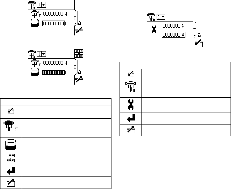
Setup Screen 6
Usethisscreentoviewthegrandtotalizervalueand
set or reset the batch totalizer.
Figure 28 Setup Screen 6
Figure 29 Reset the Totalizer
SetupScreen6Key
Enter the screen to set or change
preferences.
Grand Totalizer - displays the current
grand total of pump cycles. Not
resettable.
Batch Totalizer - displays the batch total
in selected volume units.
Reset Batch Totalizer - resets the batch
totalizer to zero.
Press to accept the selections.
Exit data editing.
SetupScreen7
Use this screen to set the desired maintenance
interval (in cycles) for each pump. The screen also
displays the current cycle count. An Advisory is
issued when the counter reaches 0 (zero).
Figure 30 Setup Screen 7
Setup Screen7Key
Enter the screen.
For systems with multiple pumps and
one display, select the desired pump (1
to 8), using the pull-down menu.
Set the desired maintenance interval (in
cycles) for each pump.
Press to accept the selections.
Exit the screen.
3A2527E 23
Setup Screens
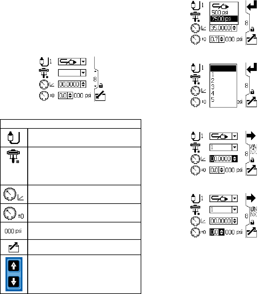
Setup Screens 8 and 9
Use these screens to set up the pressure transducers.
The screens are identical, except Screen 8 is for
transducer 1 and Screen 9 is for transducer 2.
Selecting a transducer and a pump activates closed
loop pressure control.
Figure 31 Setup Screens 8 and 9 (Screen 8 shown)
Setup Screens 8 and 9 Key
Select from the dropdown options to
enable the transducer.
For systems with multiple pumps and
one display, select the desired pump (1
to 8), using the pull-down menu. Enables
closed loop pressure control and assigns
the transducer to a pump.
Enter the calibration scale factor from the
transducer label.
Enter the calibration offset value from the
transducer label.
Displays the current transducer reading.
Exit data editing.
Move between Setup Screens, fields on
a screen, or to increment/decrement the
digits when editing number fields.
Figure 32 Select Pressure Transducer
Figure 33 Select Pump, to Enable Closed Loop
Pressure Control
Figure 34 Enter Calibration Scale Factor
Figure 35 Enter Calibration Offset Value
243A2527E
Setup Screens
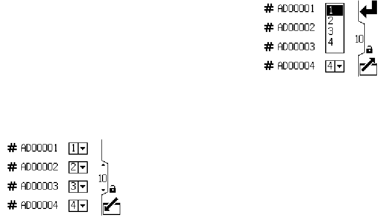
Setup Screens 10 and 11
These screens are auto-populated by the software.
Screen 10 displays the serial numbers of motors 1–4,
and Screen 11 displays the serial numbers of motors
5–8.
NOTE: Changing the pump order will shift every other
pump up one position. For example, if AD00001 is
changed to be pump 4, AD00002 will become pump
1, AD00003 will become pump 2, and so on.
Figure 36 Setup Screens 10 and 11 (Screen 10
shown)
Figure 37 Select a Pump Number for Each Serial
Number
3A2527E 25
Setup Screens
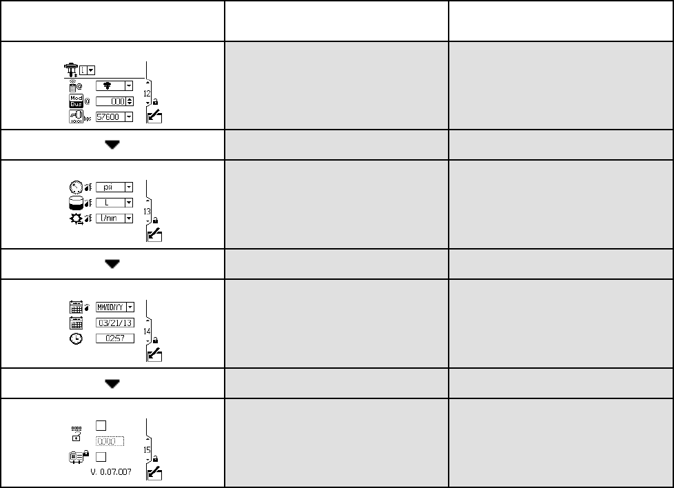
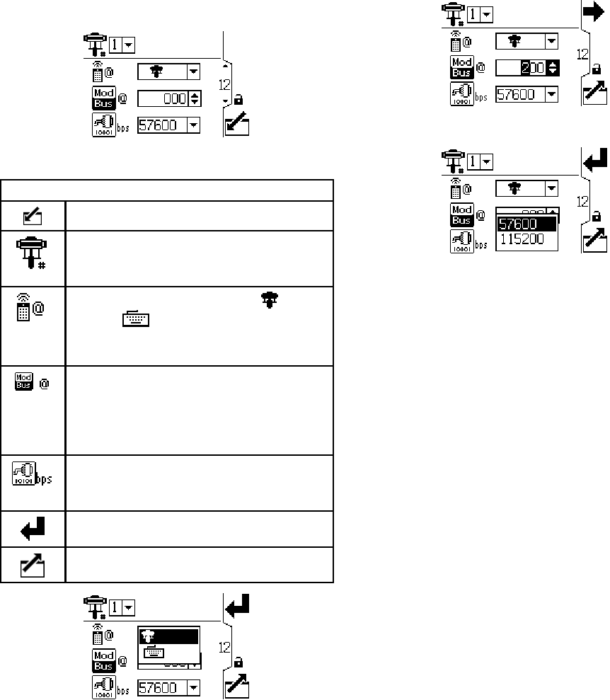
Setup Screen 12
Use this screen to set your modbus preferences.
Figure 38 Setup Screen 12
Setup Screen 12 Key
Enter the screen.
For systems with multiple pumps and
one display, select the desired pump (1
to 8), using the pull-down menu.
Control location. Select local or
remote control from the dropdown
options. Setting applies to the selected
pump only.
Enter or change the Modbus node ID.
Value is between 1 and 247. Each
pump requires a unique node ID, which
identifies that pump if more than one
pump is connected to the display..
Select serial port baud rate from the
dropdown options: 57600 or 115200.
This is a system-wide setting.
Press to accept the selections.
Exit data editing.
Figure 39 Select Local or Remote Control
Figure 40 Set Modbus Node ID
Figure 41 Set Baud Rate (Bits Per Second)
NOTE:The following are fixed modbus settings,
which cannot be set or changed by the user: 8 data
bits, 2 stop bits, no parity.
26 3A2527E
Setup Screens
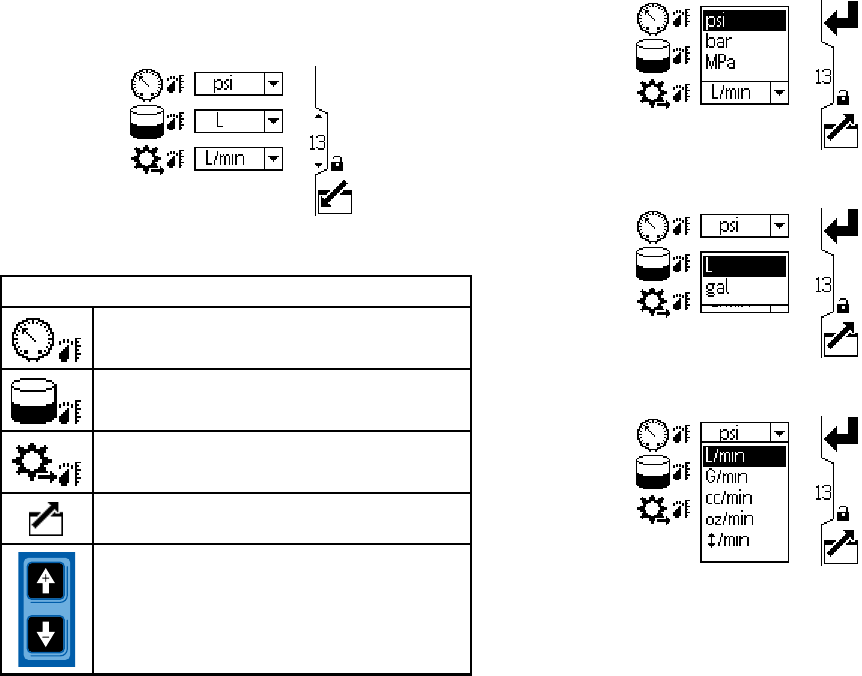
SetupScreen1
3
Use this screen to set the desired units for pressure,
totals, and flow.
Figure 42 Setup Screen 13
Setup Screen 13 Key
Select desired pressure units (psi, bar,
or MPa)
Select desired volume units (liters or
gallons)
Select desired flow rate units (L/min,
gpm, cc/min, oz/min, or cycles/min)
Exit data editing.
Move between Setup Screens, fields on
a screen, or to increment/decrement the
digits when editing number fields.
Figure 43 Select Desired Pressure Units
Figure 44 Select Desired Volume Units
Figure 45 Select Desired Flow Rate Units
3A2527E 27
Setup Screens
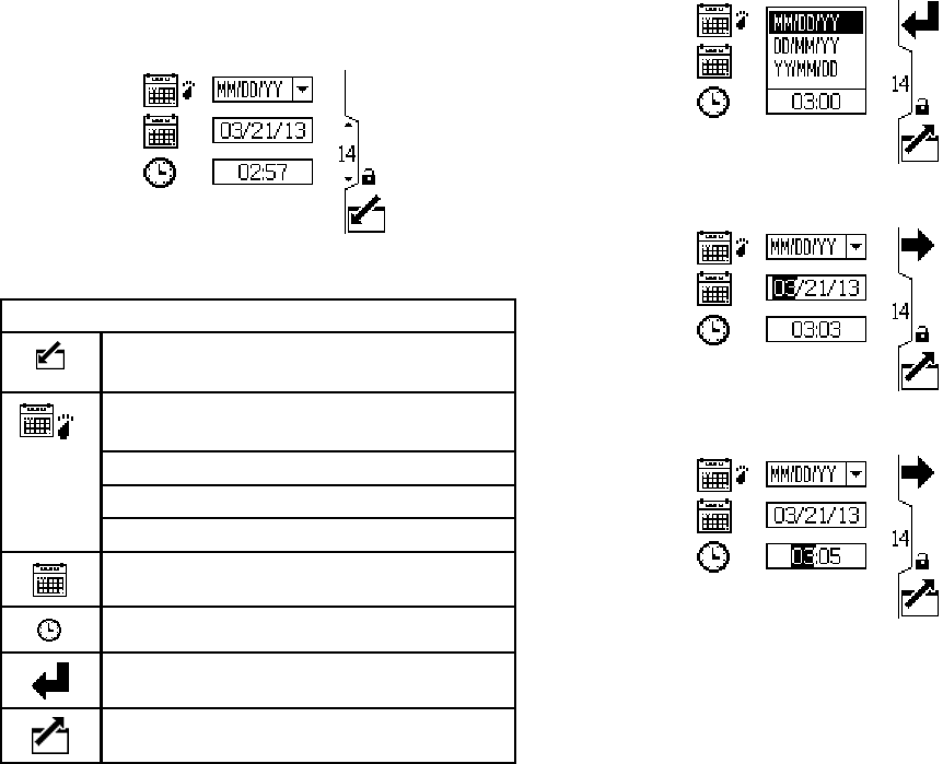
Setup Screen 14
Use this screen to set your date format, date, and
time.
Figure 46 Setup Screen 14
SetupScreen14Key
Enter the screen to set or change
preferences.
Select your preferred date format from
the dropdown menu.
MM/DD/YY
DD/MM/YY
YY/MM/DD
Set the correct date.
Set the correct time.
Press to accept the selections.
Exit data editing.
Figure 47 SelecttheDateFormat
Figure 48 Set the Date
Figure 49 Set the Time
28 3A2527E
Setup Screens
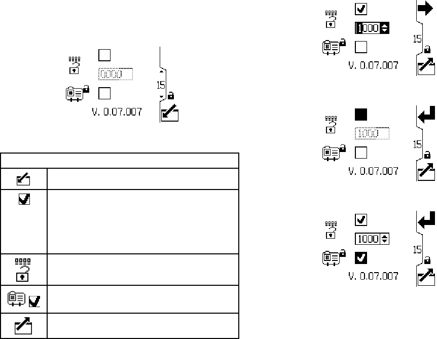
SetupScreen1
5
Use this screen to enter a password that will be
required to access the Setup screens. This screen
also displays the software version.
Figure 50 Setup Screen 15
Setup Screen 15 Key
Enter the screen to set the password.
When the top box of the screen is
checked, the password is active. To
temporarily disable the password,
uncheck the box. The password field will
be grayed-out.
Enter the desired 4–digit password.
Check the box to lock out the profile field
in the Run screens.
Exit data editing.
Figure 51 SetthePassword
Figure 52 Disable the Password
Figure 53 Lock the Profile
3A2527E 29
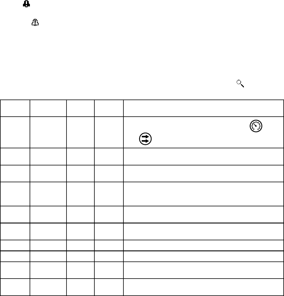
Error Code Troubleshooting
Error Code Troubleshooting
Error codes can take three forms:
•Alarm : alerts you to the alarm cause and shuts
down the pump.
• Deviation : alerts you to the problem, but pump
may continue to run past the set limits until the
system’s absolute limits are reached.
• Advisory: information only. Pump will continue to
operate.
NOTE: On Advanced motors, flow (K codes) and
pressure (P codes) can be designated as alarms or
deviations. See Setup Screen 4, page 20.
NOTE: In the error codes listed below, an “X” means
the code is associated with the display only.
NOTE: In the error codes listed below, a “_” in the
code is a placeholder for the number of the pump
where the event occurred.
NOTE: The blink code is displayed using the power
indicator on the motor. The blink code given below
indicates the sequence. For example, blink code 1–2
indicates 1 blink, then 2 blinks; the sequence then
repeats.
NOTE: A blink code of 9 is not an error code, but an
indicator of which pump is active ( softkey has
been pushed, see RunScreen1,page12).
Display
Code
Applicable
Motor
Blink
Code
Alarm or
Deviation
Description
None Basic 6 Alarm
The Mode Select knob is set between Pressure and
Flow . Set knob to the desired mode.
None Basic and
Advanced
9 None A blink code of 9 is not an error code, but an indicator of
which pump is active.
CAC_ Advanced None Alarm Display detects a loss of CAN communication. Flashing
alarm appears on the display, and the blink code occurs.
CAD_ Advanced 2–3 Alarm Unit detects a loss of CAN communication. This alarm is only
logged. No flashing alarm appears on the display, but the
blinkcodedoesoccur.
CAG_ Advanced 2–4 Alarm Display detects a loss of modbus communication when
control access is set to modbus.
CCN_ Basic and
Advanced
3–6 Alarm Circuit board communication failure.
K1D_ Advanced 1–2 Alarm Flow is below minimum limit.
K2D_ Advanced None Deviation Flow is below minimum limit.
K3D_ Advanced None Deviation Flow exceeds maximum target; also indicates pump runaway
condition exists.
K4D_ Basic and
Advanced
1 Alarm Flow exceeds maximum target; also indicates pump runaway
condition exists.
30 3A2527E

Error Code Troubleshooting
Display
Code
Applicable
Motor
Blink
Code
Alarm or
Deviation
Description
MND_ Advanced None Advisory Maintenance counter is enabled and countdown reached
zero (0).
P1I_ Advanced 1–3 Alarm Pressure is below minimum limit.
P2I_ Advanced None Deviation Pressure is below minimum limit.
P3I_ Advanced None Deviation Pressure exceeds maximum target.
P4I_ Advanced 1–4 Alarm Pressure exceeds maximum target.
P5DX Advanced None Deviation More than onepumpisassignedtoatransducer. The
assignment for that transducer is automatically cleared under
this condition. User must reassign.
P6CA or
P6CB
Advanced None Deviation For units without closed loop pressure control: Transducer (A
or B) is enabled but not detected.
P6D_ Advanced 1–6 Alarm For units with closed loop pressure control: Transduceris
enabled but not detected.
T2D_ Basic and
Advanced
3–5 Alarm Internal thermistor disconnected.
T3D_ Basic and
Advanced
5Deviation Over temperature.
V1I_ Basic and
Advanced
2 Alarm Brown out; voltage supplied to motor is too low.
V1M_ Basic and
Advanced
2–6 Alarm AC power is lost.
V4I_ Basic and
Advanced
3 Alarm Voltage supplied to motor is too high.
WMC_ Basic and
Advanced
4–5 Alarm Internal software error.
WNC_ Basic and
Advanced
3–4 AlarmSoftware versions do not match.
WSC_ Advanced None Deviation Profile is set to 0 pressure or 0 flow.
WSD_ Advanced 1–5 Alarm Invalid lower size; occurs if the unit is operated before setting
up the lower size.
WXD_ Basic and
Advanced
4Alarm
An internal circuit board hardware failure is detected.
3A2527E 31

Parts
Parts
24P822 Control Module Kit
Ref Part Description Qty
1 24P821 DISPLAY KIT, control
module; includes
item 1a; see manual
332013 for approvals
information about the
bare ADCM module
1
1a▲ 16P265 LABEL, warning,
English
1
1b▲ 16P265 LABEL, warning,
French
1
1c▲ 16P265 LABEL, warning,
Spanish (shipped
loose)
1
524N910 CONNECTOR,
jumper; includes
item 5a
1
5a ——— SCREW, cap, socket
head; M5 x 40 mm
1
6 24P823 BRACKET KIT,
control module;
includes items 6a-6f
1
Ref Part Description Qty
6a ——— BRACKET, control
module
1
6b ——— BRACKET, mounting 1
6c ——— LOCKWASHER,
external tooth; M5
4
6d ——— WASHER; M5 2
6e ——— SCREW, cap, socket
head; M5 x 12 mm
2
6f ——— KNOB; M5 x 0.8 2
11 ——— HOLDER, tie 1
12 ——— STRAP, tie 1
▲ Replacement Danger and Warning labels, tags,
and cards are available at no cost.
Items marked — — — are not available separately.
Cable (C) is shown for reference but is not included
in the kit. Order desired length separately. See
Cable Connection, page 5 .
32 3A2527E
Parts
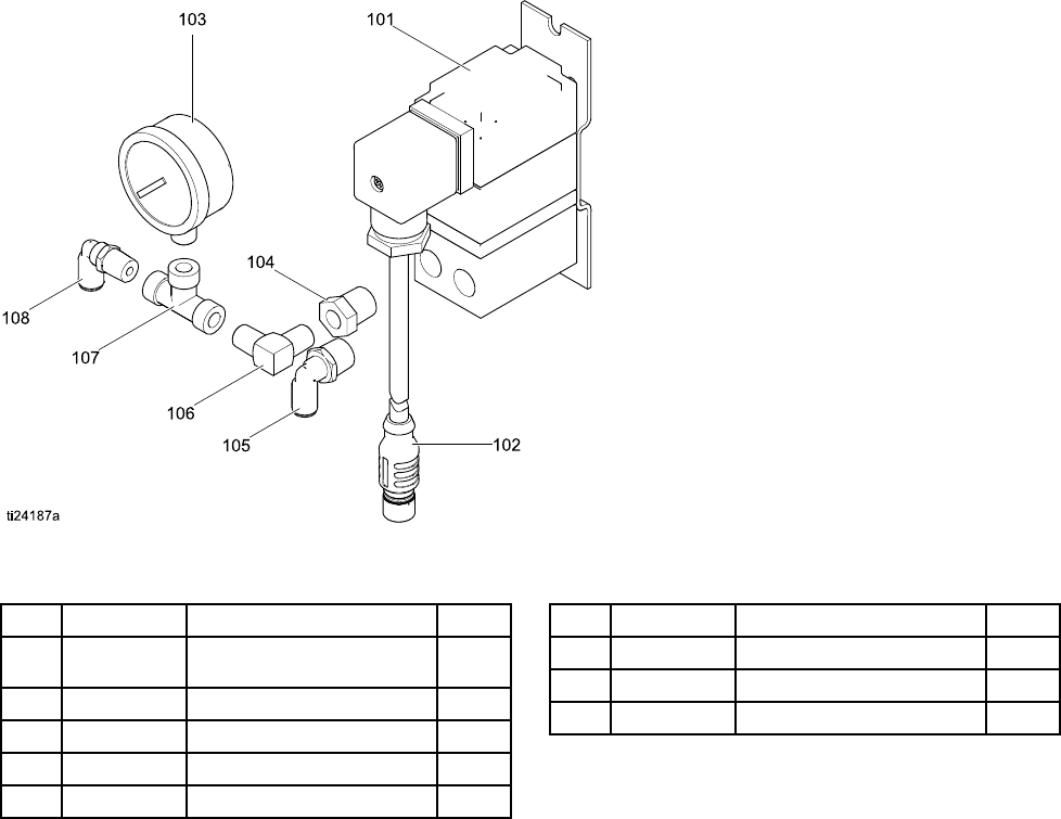
Accessory Kits
BPR Controller Kit 24V001
Ref Part Description Qty
101 ——— TRANSDUCER,
miniature
1
102 ——— CABLE, F/C, I.S., 8 M 1
103 110436 GAUGE, pressure, air 1
104 100030 BUSHING 1
105 198178ELBOW 1
Ref Part Description Qty
106 110207 ELBOW 1
107 C19466 TEE 1
108 198171 ELBOW 1
———
Parts not sold separately.
Start/Stop Switch Kit 16U729
The kit includes the switch and enclosure, a mounting bracket, and cables. Parts are not sold separately.
Pressure Transducer Kit 24R050 (for 4–Ball pumps)
and Kit 24Y245 (for 2–Ball pumps)
Each kit includes the fluid pressure sensor with cable, an adaptor, and an o-ring. Parts are not sold separately.
3A2527E 33

Appendix A - Modbus Variable Map
Appendix A - Modbus Variable Map
To communicate through fiber optics with the E-Flo
DC Control Module, reference the appropriate
hardware as shown in manual 332356. That
manual indicates various options for connecting
fiber optic cables from the control module to the
non-hazardous area. The following table lists
Modbus registersavailabletoaPCorPLClocatedin
the non-hazardous area.
Table 4 shows the registers needed for basic
operation, monitoring, and alarm control features.
Tables 5 and 6 provide bit definitions as needed for
certain registers. Table 7 shows the units and how to
convert the register value to a unit value.
Reference the Modbus communication settings
selected in Setup Screen 12, page 26.
Table 4 Modbus Registers
Modbus
Register
Variable Register
Access
Size Notes/Units
404100 Pump Status Bits Read Only 16 Bit See Table 5 for bit definitions.
404101 Actual Pump Speed Read Only 16 Bit Speed units, see Table 7.
404102 Actual Pump Flow Rate Read Only 16 Bit Flow units, see Table 7..
404103 Actual Pump Pressure Read Only 16 Bit Percent pressure, see Table 7.
404104 Transducer 1 Pressure Read Only 16 Bit Pressure units, see Table 7.
404105 Transducer 2 Pressure Read Only 16 Bit Pressure units, see Table 7.
404106 Batch Total High Word Read Only 16 Bit Volume units, see Table 7.
404107Batch Total Low Word Read Only 16 Bit Volume units, see Table 7.
404108 Grand Total High Word Read Only 16 Bit Pump cycles, see Table 7.
404109 Grand Total Low Word Read Only 16 Bit Pump cycles, see Table 7.
404110 Maintenance Total High Word Read Only 16 Bit Pump cycles, see Table 7.
404111 Maintenance Total Low Word Read Only 16 Bit Pump cycles, see Table 7.
404112 Pump Alarms High Word Read Only 16 Bit See Table 5 for bit definitions.
404113 Pump Alarms Low Word Read Only 16Bit See Table 5 for bit definitions.
404114 Display Alarms High Word Read Only 16 Bit See Table 5 for bit definitions.
404115 Display Alarms Low Word Read Only 16 Bit See Table 5 for bit definitions.
404200 Local/Remote Control Read / Write 16 Bit 0 = local, 1 = remote/PLC
404201 Active Profile Number Read / Write 16 Bit 0 = stopped, 1, 2, 3, 4
404202 Pump Control Bitfield Read / Write 16 Bit See Table 5 for bit definitions.
404203 Maintenance Interval High Word Read / Write 16 Bit Pump cycles, see Table 7.
404204 Maintenance Interval Low Word Read / Write 16 Bit Pump cycles, see Table 7.
403102 Display seconds Read Only 16 Bit Use as heartbeat.
34 3A2527E

Appendix A - Modbus Variable Map
NOTE: See Error Code Troubleshooting, page 30, for a description of each alarm.
Table 5 Alarm Bits
404112 - Pump Alarms Word 1
Bit Event Type Event Code Event Name
0 Deviation T3D_ Over Temperature
2 Alarm P6D_ Pressure Transducer Missing
3 Deviation ERR_ Internal Software Error
4 Advisory MND_ Maintenance Count
5Alarm V1M_ AC Power Loss
6 Alarm T2D_ Low Temperature
7Alarm WNC_ Version Mismatch
8Alarm CCN_ IPC Communication
9Alarm WMC_ Internal software error
10 Deviation P5D_ Multiple Pumps Assigned to Transducer
11 Deviation WSC_ Zero setting on active profile
others Reserved
404113 - Pump Alarms Word 2
Bit Event Type Event Code Event Name
0Ala
rm K1D_Minimum Speed
1 Deviation K2D_ Minimum Speed
2Alarm K4D_ Maximum Speed
3D
eviation K3D_ Maximum Speed
4 Alarm P1I_ Minimum Pressure
5Deviation P2I_ Minimum Pressure
6 Alarm P4I_ Maximum Pressure
7Deviation P3I_ Maximum Pressure
8 Alarm V1I_ Under Voltage
9Alarm V4I_ Over Voltage
10 Alarm V4I_ High Pressure 120V
11 Alarm CAD_ CAN Communication Pump
13 Alarm WXD_ Board Hardware
14 Alarm WSD_ Invalid Lower Size
others Reserved
3A2527E 35

Appendix A - Modbus Variable Map
404114 - Display Alarms Word 1
Bit Event Type Event Code Event Name
1 Deviation P6C_ Pressure Transducer Missing
others Reserved
404115 - Display Alarms Word 2
Bit Event Type Event Code Event Name
12 Alarm CAG_ Modbus Communication
15 Alarm CAC_ CAN Communication Display
others Reserved
Table 6 Pump Status and Control Bits
404100 - Pump Status Bits
Bit Meaning
0Reads 1 ifthepumpistryingtomove
1Reads 1 if the pump is actually moving
2Reads 1 if there are any active alarms
3Reads 1 if there are any active deviations
4Reads 1 if there are any active advisories
others Reserved for future use
404202 - Pump Control Bits
Bit Meaning
0Reads 0 for an active alarm or deviation. Reset to 1 to clear.
1Setto1toresetthebatchtotal
2Set to 1 to reset the maintenance counter
others Reserved for future use - only write 0
36 3A2527E

Appendix A - Modbus Variable Map
Table 7 Units
Unit Type Selectable Units Units Register Converting registers to
unit values
Register valuefor1
unit
Pressure Percent n/a Pressure = Register 1=1%Pressure
psi 403208 = 0 Pressure = Register 1=1psi
Bar 403208 = 1 Pressure = Register/10 10 = 1.0 Bar
Pressure
MPa 403208 = 2 Pressure =
Register/100
100 = 1.00 Mpa
Speed Cycles/min n/a Speed = Register/10 10 = 1.0 cycle/min
Liters/min 403210 = 0 Flow = Register/10 10 = 1.0 L/min
Gallons/min 403210 = 1 Flow = Register/10 10 = 1.0 Gal/min
cc/min 403210 = 2 Flow = Register 1 = 1 cc/min
oz/min 403210 = 3Flow = Register 1=1oz/m
in
Flow
Cycles/min 403210 = 4 Flow = Register/10 10 = 1.0 cycle/min
Liters 403209 = 0 Volume = 1000*High +
Low/10
0 (High) / 10 (Low) =
1.0 L
Volume✝
Gallons 403209 =1 Volume = 1000*High +
Low/10
0 (High) / 10 (Low) =
1.0 Gal
Cycles✝✝ Pump Cycles n/a Cycles = 10000*High
+Low
0(Hig
h) / 1 (Low) = 1
cycle
✝Example of converting volume register reading to units: If the reading for register 404106 (volume high
word) is 12, and the reading for register 404107 (volume low word) is 34, the volume is 12003.4 liters. 12 *
1000 + 34/10 = 12003.4.
✝✝ Example of converting cycles register reading to units: If the reading for register 404108 (cycles high
word) is 75, and the reading for register 404109 (cycles low word) is 8000, the volume is 758,000 cycles.
75 * 10000 + 8000 = 758000.
3A2527E 37
Appendix B. Pump Control from a PLC
Appendix B. Pump Control from a PLC
This guide shows how to use the information in
Appendix A to control a pump remotely from a PLC.
The steps progress from basic pump control to more
advanced monitoring and alarm control features.
It is important that you first follow all directions in the
Setup Screens to configure your system properly.
Test that the pump operates correctly when controlled
from the Display. Make sure the display, fiber optics,
communication gateway, and PLC are connected
properly. Refer to Communication KIt manual. Use
Setup Screen 12 to enable remote control and set
your modbus preferences.
1. Enable PLC control: Set register 404200 to 1.
2. Run a pump: Set register 404201. Enter 0 for
stopped,1 to 4 for the desired profile.
3. View pump profile: Read register 404201. This
register updates automatically to reflect the
actual pump status. If the profile is changed from
the display, this register changes as well. If the
pump stops due to an alarm, this register will
read 0.
4. View pump status: Read register 404100 to see
the status of the pump. See Appendix A, Table
6, for a description of each bit.
• Example 1: Register 404100, bit 1, reads 1 if
the pump is currently moving.
• Example 2: Register 404100, bit 2 reads 1 if
the pump has an active alarm.
5. Monitor alarms and deviations: Read register
404112 to 404115. Each bit in these registers
corresponds to an alarm or deviation. See
Appendix A, Table 5. I
• Example 1: Pressure falls below the minimum
setting entered on Setup Screen 2. It will show
on bit 4 of register 404113 if minimum pressure
is set to Alarm, and on bit 5 of register 404113
if minimum pressure is set to Deviation.
•Example2:The system is set up for a
pressure transducer on Setup Screen 8, but no
transducer is detected. It will show on bit 1 of
register 404114.
6. Monitor pump cycle rate, flow rate, and pressure:
Read registers 404101 to 404105. Note that
pressure is available only if a pressure transducer
is connected to the display. Register 404104
shows the pressure on transducer 1. Register
404105 shows the pressure on transducer 2. See
Appendix A, Table 7 for units for these registers.
• Example 1: If register 404101 reads 75, the
pump speed is 7.5 cycles/minute.
•Exampl
e 2: If register 404103 reads 67, the
pump is operating at 67 percent pressure.
7. Reset active alarms and deviations: Clear the
condition that caused the alarm. Set register
404202, bit 0, to 1 to clear the alarm. The pump
will be in profile 0 due to the alarm. Set 404201
to the desired profile to run the pump again.
38 3A2527E


Graco Standard Warranty
Graco warrants all equipment referenced in this document which is manufactured by Graco and bearing its
name to be free from defects in material and workmanship on the date of sale to the original purchaser for
use. With the exception of any special, extended, or limited warranty published by Graco, Graco will, for a
period of twelve months from the date of sale, repair or replace any part of the equipment determined
by Graco to be defective. This warranty applies only when the equipment is installed, operated and
maintained in accordance with Graco’s written recommendations.
This warranty does not cover, and Graco shall not be liable for general wear and tear, or any malfunction,
damage or wear caused by faulty installation, misapplication, abrasion, corrosion, inadequate or improper
maintenance, negligence, accident, tampering, or substitution of non-Graco component parts. Nor shall
Graco be liable for malfunction, damage or wear caused by the incompatibility of Graco equipment
with structures, accessories, equipment or materials not supplied by Graco, or the improper design,
manufacture, installation, operation or maintenance of structures, accessories, equipment or materials
not supplied by Graco.
This warranty is conditioned upon the prepaid return of the equipment claimed to be defective to an
authorized Graco distributor for verification of the claimed defect. If the claimed defect is verified, Graco
will repair or replace free of charge any defective parts. The equipment will be returned to the original
purchaser transportation prepaid. If inspection of the equipment does not disclose any defect in material
or workmanship, repairs will be made at a reasonable charge, which charges may include the costs of
parts, labor, and transportation.
THIS WARRANTY IS EXCLUSIVE, AND IS IN LIEU OF ANY OTHER WARRANTIES, EXPRESS OR
IMPLIED, INCLUDING BUT NOT LIMITED TO WARRANTY OF MERCHANTABILITY OR WARRANTY
OF FITNESS FOR A PARTICULAR PURPOSE.
Graco’s sole obligation and buyer’s sole remedy for any breach of warranty shall be as set forth above.
The buyer agrees that no other remedy (including, but not limited to, incidental or consequential damages
for lost profits, lost sales, injury to person or property, or any other incidental or consequential loss) shall
be available. Any action for breach of warranty must be brought within two (2) years of the date of sale.
GRACO MAKES NO WARRANTY, AND DISCLAIMS ALL IMPLIED WARRANTIES OF
MERCHANTABILITY AND FITNESS FOR A PARTICULAR PURPOSE, IN CONNECTION WITH
ACCESSORIES, EQUIPMENT, MATERIALS OR COMPONENTS SOLD BUT NOT MANUFACTURED BY
GRACO. These items sold, but not manufactured by Graco (such as electric motors, switches, hose, etc.),
are subject to the warranty, if any, of their manufacturer. Graco will provide purchaser with reasonable
assistance in making any claim for breach of these warranties.
In no event will Graco be liable for indirect, incidental, special or consequential damages resulting from
Graco supplying equipment hereunder, or the furnishing, performance, or use of any products or other
goods sold hereto, whether due to a breach of contract, breach of warranty, the negligence of Graco, or
otherwise.
FOR GRACO CANADA CUSTOMERS
The Parties acknowledge that they have required that the present document, as well as all documents,
notices and legal proceedings entered into, given or instituted pursuant hereto or relating directly or
indirectly hereto, be drawn up in English. Les parties reconnaissent avoir convenu que la rédaction du
présente document sera en Anglais, ainsi que tous documents, avis et procédures judiciaires exécutés,
donnés ou intentés, à la suite de ou en rapport, directement ou indirectement, avec les procédures
concernées.
Graco Information
For the latest information about Graco products, visit www.graco.com.
For patent information, see www.graco.com/patents.
To place an order, contact your Graco Distributor or call to identify the nearest distributor.
Phone: 612-623-6921 or Toll Free: 1-800-328-0211 Fax: 612-378-3505
All written and visual data contained in this document reflects the latest product information available at the time of publication. Graco
reserves the right to make changes at any time without notice
Original Instructions. This manual contains English. MM 3A2527
Graco Headquarters: Minneapolis
International Offices: Belgium, China, Japan, Korea
GRACO INC. AND SUBSIDIARIES • P.O. BOX 1441 • MINNEAPOLIS MN 55440-1441 • USA
Copyright 2013, Graco, Inc. All Graco manufacturing locations are registered to ISO 9001.
www.graco.com
Revision E, April 2015
