User manual
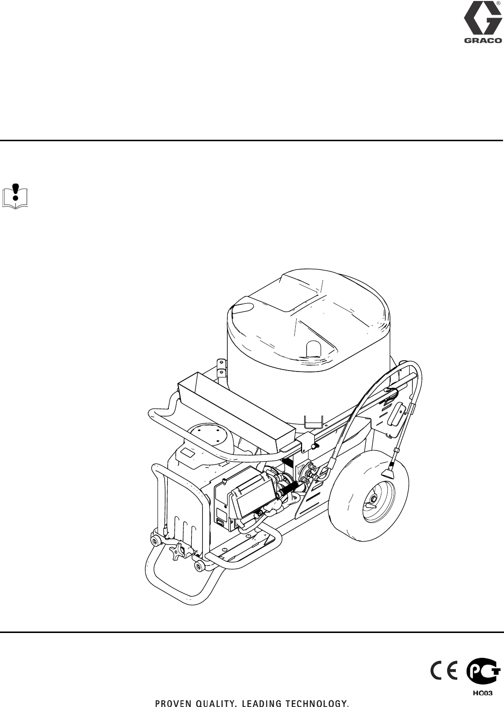
Operation
Drywall Feed Pump
- For Water-Based Materials Only -
Maximum Working Pressure 2500 psi (17.2 MPa, 172 bar)
Model: 257100
Read all warnings and instructions
3A0245A
ti14873a
Warning
23A0245A
Warning
The following warnings are for the setup, use, grounding, maintenance, and repair of this equipment. The exclama-
tion point symbol alerts you to a general warning and the hazard symbol refers to procedure-specific risk. Refer back
to these warnings. Additional, product-specific warnings may be found throughout the body of this manual where
applicable.
WARNING
FIRE AND EXPLOSION HAZARD
Flammable fumes, such as solvent, in work area can ignite or explode. To help prevent fire and explo-
sion:
• Keep work area free of debris, including solvent, rags and gasoline.
• Ground equipment in the work area. See Grounding instructions.
• If there is static sparking or you feel a shock, stop spraying immediately. Do not use equipment
until you identify and correct the problem.
EQUIPMENT MISUSE HAZARD
Misuse can cause death or serious injury.
• Do not exceed the maximum working pressure or temperature rating of the lowest rated system
component. See Technical Data in all equipment manuals.
• Use water-based materials. Use fluids and solvents that are compatible with equipment wetted
parts. See Technical Data in all equipment manuals. Read fluid and solvent manufacturer’s warn-
ings.
• Check equipment daily. Repair or replace worn or damaged parts immediately.
• Do not alter or modify equipment.
• Use equipment only for its intended purpose. Call your Graco distributor for information.
• Route hoses and cables away from traffic areas, sharp edges, moving parts, and hot surfaces.
• Do not use hoses to pull equipment.
• Keep children and animals away from work area.
• Comply with all applicable safety regulations.
PRESSURIZED EQUIPMENT HAZARD
Fluid from the gun/dispense valve, leaks, or ruptured components can splash in the eyes or on skin and
cause serious injury.
• Follow Pressure Relief Procedure in this manual, when you stop spraying and before cleaning,
checking, or servicing equipment.
• Tighten all fluid connections before operating the equipment.
• Check hoses, tubes, and couplings daily. Replace worn or damaged parts immediately.
PERSONAL PROTECTIVE EQUIPMENT
You must wear appropriate protective equipment when operating, servicing, or when in the operating
area of the equipment to help protect you from serious injury, including eye injury, inhalation of toxic
fumes, burns, and hearing loss. This equipment includes but is not limited to:
• Protective eye wear
• Clothing and respirator as recommended by the fluid and solvent manufacturer
•Gloves
• Hearing protection

Warning
3A0245A 3
MOVING PARTS HAZARD
Moving parts can pinch or amputate fingers and other body parts.
• Keep clear of moving parts.
• Do not operate equipment with protective guards or covers removed.
• Pressurized equipment can start without warning. Before checking, moving, or servicing equipment,
follow the Pressure Relief Procedure in this manual. Disconnect power or air supply.
WARNING
Component Identification
43A0245A
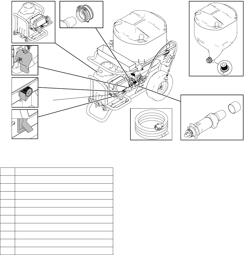
Component Identification
1 Pump Module
2 Prime/Tool Fill/Recirculation Valve
3 Flow Knob
4 15/20 Amp Switch
5 ON/OFF Switch
6 Material Hoses
7Pump
8 Pump Inlet Cover
9 Hopper Plug
10 Hopper
11 Pump Connector
1
2
3
4
56
7
8
ti14874a
9
10
11
Finishing Tools
3A0245A 5
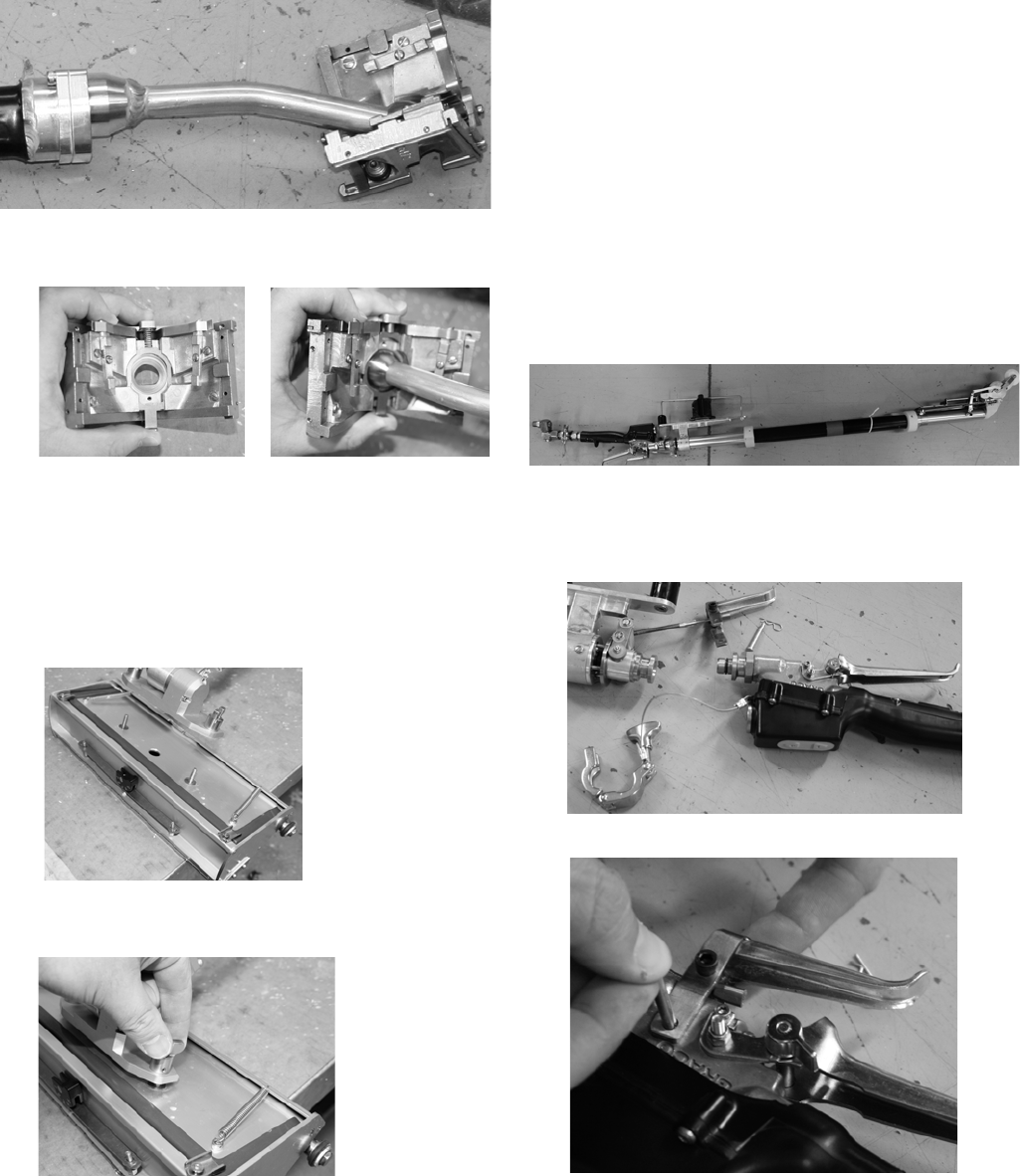
Finishing Tools
Corner Finisher
1. Press pin on top of corner finisher and install onto
valve.
2. Work from bottom to top of vertical angles and from
one end to other on ceiling angles.
3. Use drywall knife to detail corner and ceiling angle
intersections.
Flat Finishing Box
1. Install valve over two screws on box and tighten two
wing nuts.
2. Place flat box at end of joint.
3. Lead with handle and draw the tool along the joint.
4. Near middle of the joint, remove flat box from joint
surface with a sweeping motion.
5. Reverse hand positions and begin again at other
end of joint.
6. Again draw flat box along joint up to previous
stopping point and remove box from joint surface
with a sweeping motion.
7. Use drywall knife to detail seams and overlap.
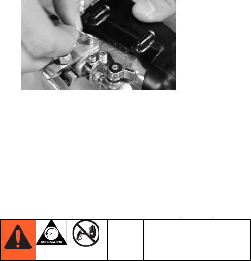
Automatic Taping Tool
NOTE: Fine flow rate adjustments can be made using
buttons on valve handle.
1. Install trigger assembly and sanitary clamp.
2. Insert pin into trigger assembly.
Pressure Relief Procedure
63A0245A
3. Insert cotter pin.
4. Place one hand on control tube and one hand at
bottom of mud tub while in use.
5. Place tape at bottom of joint (slide tube forward to
feed tape).
6. Lead with head of taper to make tracking easier.
Large trigger feeds material through tool. Small
trigger retracts creasing wheel.
7. Roll tape over seam with only one wheel in contact
with wall until approximately three inches from end
of seam.
8. Stop completely and pull tube back to cut tape.
9. Use drywall knife to detail seams and overlap.
NOTE: Clean all tools thoroughly after every use. Use a
brush and water to remove all joint compound from
tools. Once tools have been cleaned, lightly oil using
any light machine oil.
Pressure Relief Procedure
1. Turn flow control knob OFF.
2. Point applicator into hopper and trigger to relieve
pressure.
3. Fluid from pressure relief valve can splash in eyes
or skin and cause serious injury. Keep hands clear
of pressure relief valve. Wear safety glasses.
Operation
3A0245A 7
Operation
FCC Notice (FCC ID: JHICED1)
Model Number: DFS150
This device complies with Part 15 of the FCC rules.
Operation is subject to the following two conditions:
• This device may not cause harmful interference.
• This device must accept any interference that may
be received, including interference that may cause
undesired operation.
Changes or modifications not expressly approved by
Graco, Inc. could void the user's authority to operate this
equipment.
IC Notice (IC: 4840ACED1)
This product meets the applicable Industry Canada
technical specifications/Le présent materiel est con-
forme aux specifications techniques applicables
d’Industrie Canada.
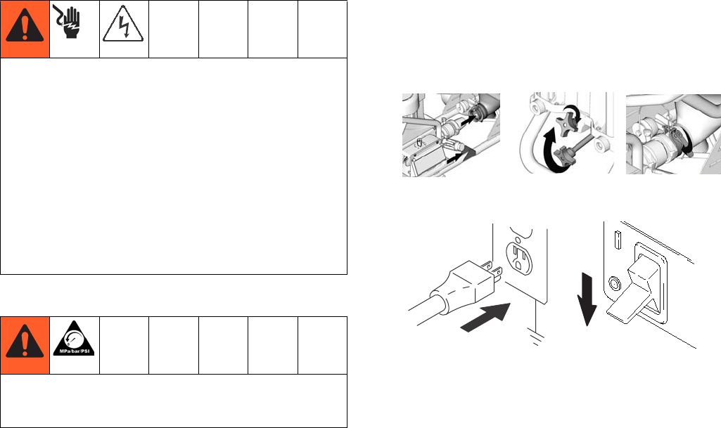
Setup
1. Connect pump module to hopper and cart. Tighten
knob on front of pump module and clamp other end
to hopper.
2. Connect power cord. Turn ON/OFF to OFF.
3. Connect material hose to outlet.
NOTE: Up to 150 ft of 1/2 in. hose plus 15 ft. x 1/4
in. can be connected to the unit. If desired flow rate
is not obtainable, reduce hose length or add addi-
tional water to mud mixture.
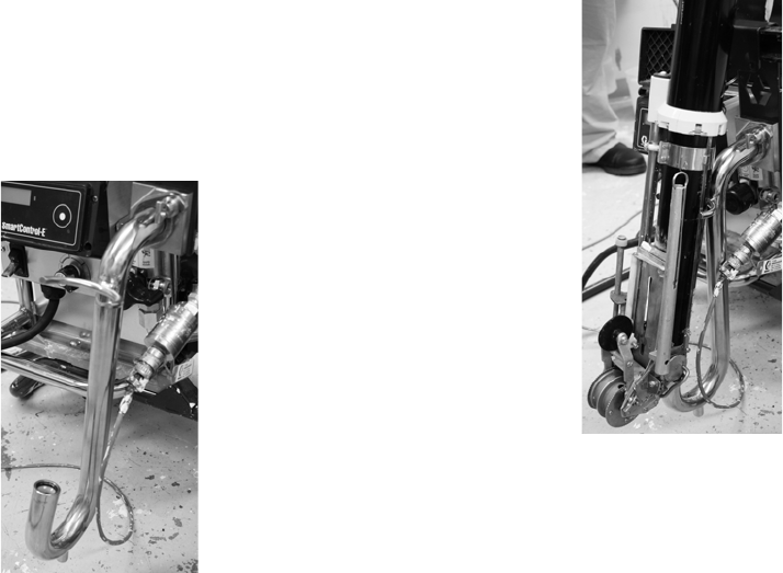
4. Select 15A/20A setting based on your circuit rating.
5. Connect Z swivel.
6. Connect selected finishing tool to Z swivel using
supplied sanitary clamps.
“Learn” the Valve
This unit performs differently depending on which valve
is being used. Each time you change valves, perform
the following steps so the unit can “Learn” the valve.
1. Turn flow control knob down (but not OFF).
2. Push digital display button 3 times until LEARN
appears on display screen.
3. Pull trigger on valve.
4. OK should then appear on display screen (if not,
see Troubleshooting).
GROUNDING INSTRUCTIONS
This appliance is rated more than 15 A and is for use
on a circuit having a nominal rating of 120 V and is fac-
tory equipped with a specific electric cord and plug. No
adapter should be used with this appliance. If the appli-
ance must be reconnected for use on a different type of
electric circuit, the reconnection should be made by
qualified service personnel; and after the reconnection,
the appliance should comply with all local codes and
ordinances.
Consult a qualified electrician if there is any doubt as to
whether an outlet box is properly grounded.
Do NOT tamper with relief valve or devices that control
maximum pressure control during normal operation.
Bodily injury and/or damaged to equipment can occur.
ti11679a ti11678a ti11673a
ti4265a
ti2810a
ti4265a
Operation
83A0245A
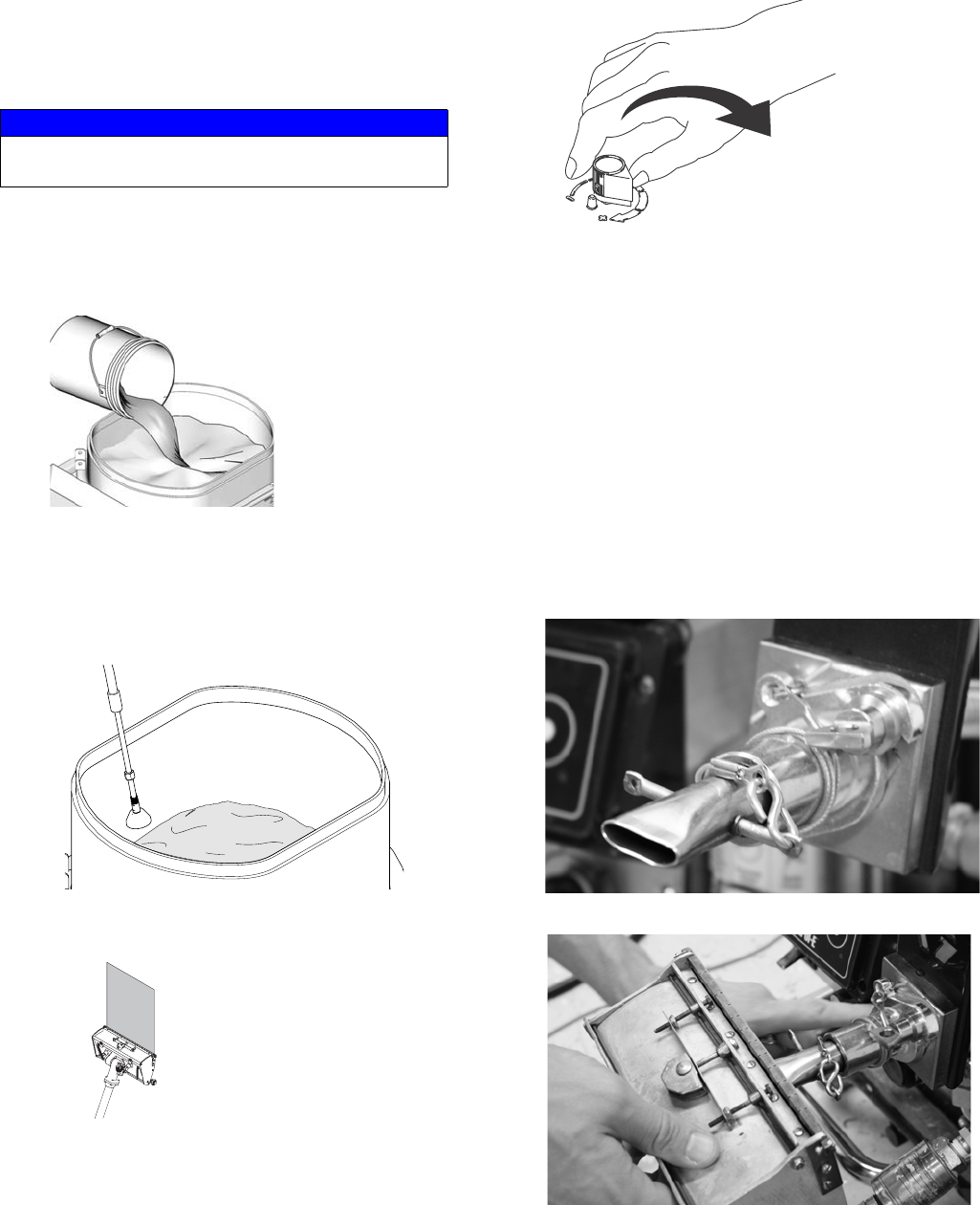
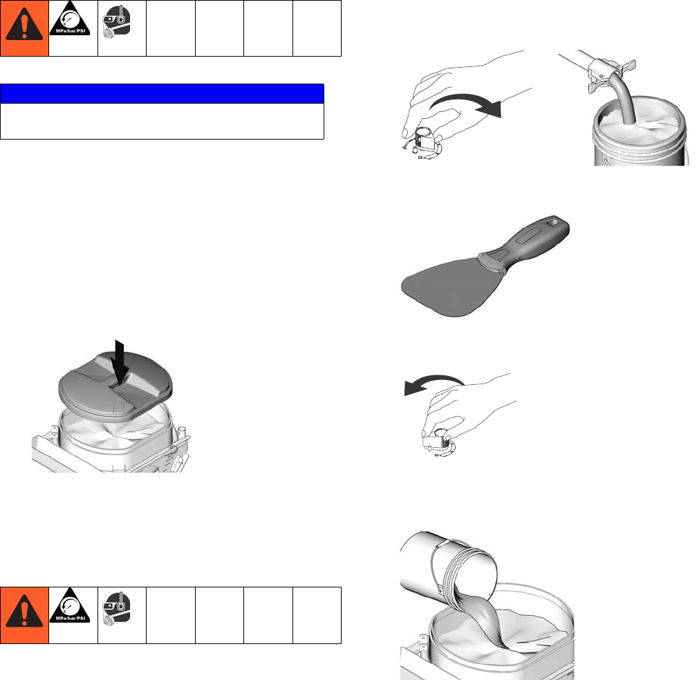
Startup
Pump Material
1. Mix material in separate bucket. Gradually add
water and mix until desired consistency is achieved.
2. Add mixed material to hopper.
3. Place deflect er into hopper to recirculated material.
NOTE: Keep deflector shield wet once it is in use.
4. Turn sprayer power ON and flip prime valve fully
clockwise to prime pump. Place material hose and
drain line in hopper.
5. After unit is primed, place prime valve in APPLY
FINISH position.
6. Turn flow knob clockwise to increase material flow.
7. Place head of tool over waster bucket and trigger
valve until material flows from tool head. Once all
water has been flushed from hose and tool, position
tool head over hopper until flow rate is determined.
8. Apply a couple of test coats to determine proper
flow speed on sprayer. Fine adjustments can be
made on valve handle to increase or decrease flow
speed.
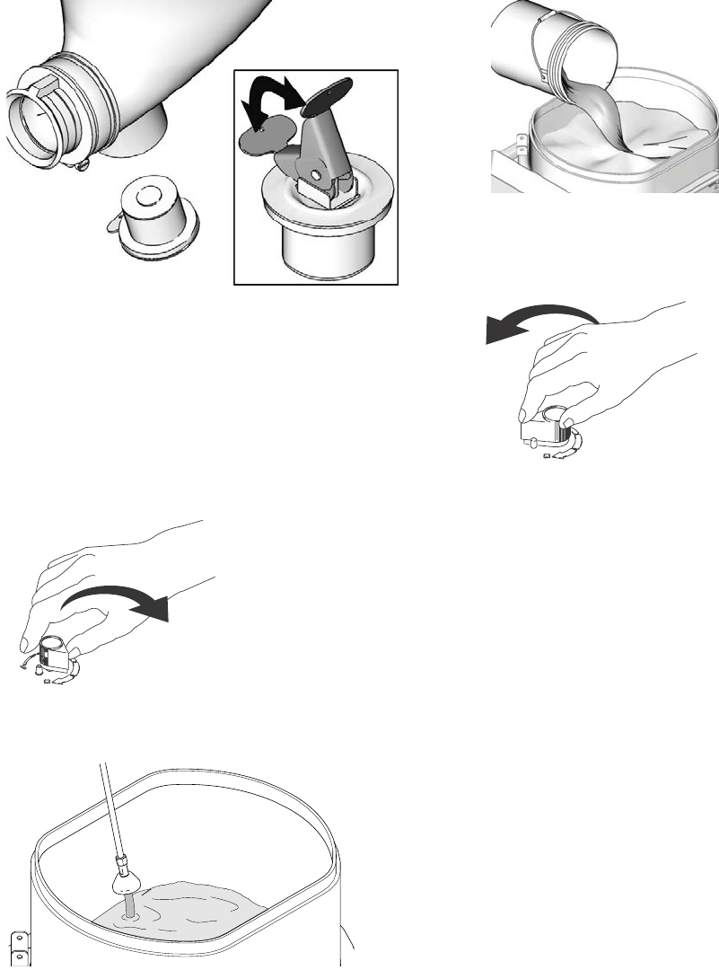
Fill Tools With Material
Fill Box
1. Remove tool-fill flange.
2. Install box fill adapter.
3. Place slot of box over box fill nozzle.
4. Turn Prime Valve to TOOL FILL position.
NOTICE
Do not use with quick-set materials. They can
harden inside the unit and hose.
ti11670a
ti14876a
Operation
3A0245A 9
5. Turn flow control knob fully clockwise until box is
filled with material.
6. Turn flow control knob fully counter-clockwise.
Fill Taper
1. Install taper-fill adapter.
2. Place material inlet of taper over nozzle of taper-fill
adapter.
3. Turn Prime Valve to TOOL FILL position.
4. Turn control knob fully clockwise.
5. Place fingers inside top of taper. When you feel the
plunger rise to the top, turn flow control knob fully
counter-clockwise.

Operation
10 3A0245A
Bleed System Pressure
1. Turn flow knob to fully counterclockwise.
2. Place deflector in hopper or suitable container.
3. Place prime valve in RELIEF position.
Remove Prime Valve
1. Use 3/32 in. punch and hammer to tap out handle
pin (pliers may be required to pull out handle pin).
2. Use crescent wrench to unscrew prime valve han-
dle.
3. Clear out any material that is lodged in valve or
manifold.
Install Prime Valve
1. Tighten prime valve into manifold (use thread seal-
ant on housing threads). Torque to 190 to 210 in-lb.
2. Install prime valve base. Pin in base must align with
hole in manifold.
3. Orient .096 in. hole in drain valve stem vertically.
4. Place drain valve over drain valve base with handle
in “apply” mode.
5. Use hammer to tap drain valve handle pin back into
place.
Cleanup
3A0245A 11
Cleanup
Storage - Less Than 24 Hours
1. Perform Pressure Relief Procedure, page 6 (valve
in down position).
2. Remove tool from valve. Clean all tools or use sup-
plied tool caps.
3. Remove hopper lid and use water bottle to spray
enough water mist to cover top layer of material.
4. Clean hopper sides to material level. Cover material
in hopper with hopper cover.
Storage - More Than 24 Hours
1. Perform Pressure Relief Procedure, page 6 (valve
in down position).
2. Hang drain line mount onto material bucket. Turn
pump to drain position and pump unused material
from hopper and hose.
3. Scrape material remaining in hopper into pump to
be pumped from sprayer.
4. Turn pump control fully counter-clockwise to shut
pump off.
5. Fill material hopper with water and run pump to
flush hose and valve. Use standard garden hose
with nozzle to wash sprayer body.
6. Shut pump off.
NOTICE
Do not use with quick-set materials. They can
harden inside the unit and hose.
ti11802a
ti8794a
ti11801a
ti11760a
ti8793a
ti11670a
Cleanup
12 3A0245A
7. Remove drain plug from hopper. Flush with water.
Clean and install drain plug.
NOTE: Cap plug must not be inserted into the female
side of the connector on the Z swivel. Residual pressure
can cause the cap plug to lose the seal. To ensure that
the cap plug properly seals, use cap plug on the inline
gun outlet.
8. Wash all tools.
9. Turn pump control clockwise to start pump.
10. Run pump until clean water flows from applicator.
Continue until hopper is empty.
11. Add additional water and repeat steps 13 - 14,
if necessary.
12. Remove drain plug from hopper. Flush with water.
Clean and install drain plug.
13. Rotate pump control to shut pump off.
ti11804a
ti8794a
ti14878a
ti11670a
ti8793a

Cleanup
3A0245A 13
Troubleshooting
Motor Won’t Operate
PROBLEM CAUSE SOLUTION
Basic Fluid Pressure Problems Pressure control knob setting. Motor will not
run if at minimum setting (fully counterclock-
wise).
Slowly increase pressure setting to see
if motor starts.
Spray tip or fluid filter may be clogged. Relieve pressure and clear clog or
clean filter; refer to separate gun or tip
instruction manual.
Basic Mechanical Problems Frozen or hardened paint. Thaw sprayer if water or water-based
paint has frozen in sprayer. Place
sprayer in warm area to thaw. Do not
start sprayer until thawed completely. If
paint hardened (dried) in sprayer,
replace pump packing. See repair man-
ual.
Displacement pump connecting rod pin. Pin
must be completely pushed into connecting
rod and retaining spring must be firmly in
groove of pump pin.
Push pin into place and secure with
spring retainer.
Motor. Remove drive housing assembly.
Try to rotate fan by hand.
Replace motor if fan won't turn.
Basic Electrical Problems Motor control board. Board shuts down and
displays error code.
See Control Board Diagnostics.
Electrical supply. Meter must read: 210-255
Vac for 220-240 Vac models;
85-130 Vac for 100-120 Vac models.
Reset building circuit breaker; replace
building fuse. Try another outlet.
Extension cord. Check extension cord conti-
nuity with volt meter.
Replace extension cord.
Sprayer power supply cord. Inspect for dam-
age such as broken insulation or wires.
Replace power supply cord.
Check that motor leads are securely fastened
and properly mated.
Replace loose terminals; crimp to
leads. Be sure terminals are firmly con-
nected. Clean circuit board terminals.
Securely reconnect leads.
ON/OFF Switch. Connect volt meter between
L1 and L2 terminal on ON/OFF switch. Plug
in sprayer and turn ON. Meter must read:
210-255 Vac for 220-240V models
85-130 Vac for 100-120V models.
Replace ON/OFF switch.
All terminals for damage or loose fit. Replace damaged terminals and
reconnect securely.

Cleanup
14 3A0245A
Motor is Hot and Runs Intermittently
Low or Fluctuating Output
PROBLEM CAUSE SOLUTION
Motor is hot and runs intermittently. Determine if sprayer was operated at
high pressure with small tips, which
causes low motor RPM and excessive
heat build up
Decrease pressure setting or increase
tip size.
Be sure ambient temperature where
sprayer is located is no more than 90°F
and sprayer is not located in direct sun
Move sprayer to shaded, cooler area if
possible.
PROBLEM CAUSE SOLUTION
Low Output Worn spray tip. Follow Pressure Relief Procedure
Warning, then replace tip. See your
separate gun or tip manual.
Verify pump does not continue to stroke
when applicator is turned off.
Service pump. Check piston and intake
valves for wear or obstructions.
Filter clogged (If optional filter is
installed).
Relieve pressure. Check and clean fil-
ter.
Material hose length. Longer hose
length reduces sprayer performance.
Replace with hose length less than
specified maximum.
Pump hopper adapter connections. Tighten any loose connections.
Replace pump hopper adapter if
cracked or punctured.
Electrical supply with volt meter. Meter
must read:
210-255 Vac for 220-240 Vac models;
85-130 Vac for 100-120 Vac models.
Low voltages reduce sprayer perfor-
mance.
Reset building circuit breaker; replace
building fuse. Repair electrical outlet or
try another outlet.
Extension cord size and length; must be
at least 1.0 mm2 (12 awg) wire and no
longer than 90 m (295 ft). Longer cord
lengths reduce sprayer performance.
Replace with a correct, grounded
extension cord.
Leads from motor to pressure control
circuit board for damaged or loose
wires or connectors. Inspect wiring
insulation and terminals for signs of
overheating.
Be sure male terminal blades are cen-
tered and firmly connected to female
terminals. Replace any loose terminal
or damaged wiring. Securely reconnect
terminals.
Low stall pressure. Turn pressure control knob fully clock-
wise. Make sure pressure control knob
is properly installed to allow full clock-
wise position. Try a new transducer.
Plugged Prime Valve Material has dried and plugged the
prime valve
Aim hose into waste pail. Turn prime
valve from tool fill to dump and then
back to tool fill. If valve remain plugged,
see Bleed System Pressure, page 10.

Cleanup
3A0245A 15
Troubleshooting
Low or Fluctuating Output
Electrical Short
PROBLEM CAUSE SOLUTION
Motor runs and pump strokes 1. Material supply. 1. Refill hopper and re-prime pump.
2. Loose fittings. 2. Tighten; use thread sealant or
sealing tape on threads if neces-
sary.
3. Intake valve ball and piston ball are
seating
properly.
3. Remove intake and piston valves
and clean. Check balls and seats
for nicks or obstructions; replace
if necessary, page 18. Clean
hopper before using to remove
particles that could clog pump.
4. Leaking around throat packing nut
which may indicate worn or damaged
packings.
4. Replace packing, page 18. Also
check piston valve seat for hard-
ened paint or nicks and replace if
necessary.
5. Pump rod damage. 5. Repair pump.
Motor runs but pump does not
stroke
1. Displacement pump pin (75) (damaged
or missing).
1. Replace pump pin if missing. Be
sure retainer spring (76) is fully in
groove all around connecting rod.
2. Connecting rod assembly (45) for dam-
age.
2. Replace connecting rod assem-
bly.
3. Gears or drive housing. 3. Inspect drive housing assembly
and gears for damage and
replace if
necessary.
PROBLEM CAUSE SOLUTION
Building circuit breaker opens
as soon as sprayer switch is
turned on.
CAUTION
Any short in any part of the
motor power circuit will cause
the control circuit to inhibit
sprayer operation. Correctly
diagnose and repair all shorts
before checking and replacing
control board.
1. All electrical wiring for damaged insula-
tion, and all terminals for loose fit or
damage. Also wires between pressure
control and motor.
1. Repair or replace any damaged
wiring or terminals. Securely
reconnect all wires.
2. Motor armature for shorts. Inspect
windings for burns
2. Replace motor.
3. Motor control board by performing
motor control board diagnostics. If
diagnostics indicate, substitute with a
good board.
3. Replace with a new pressure
control board.

Cleanup
16 3A0245A
Building circuit breaker opens
as soon as sprayer is plugged
into outlet and sprayer is NOT
turned on.
1. Basic Electrical Problems on page 13. 1. Perform necessary procedures.
2. For damaged or pinched wires in pres-
sure
control.
2. Replace damaged parts.
Sprayer quits after sprayer
operates for 5 to 10 minutes.
1. Basic Electrical Problems. 1. Perform necessary procedures.
2. Electrical supply with volt meter.
Meter must read:
210-255 Vac for 220-240 Vac models;
85-130 Vac for 100-120 Vac models.
2. If voltage is too high, do not oper-
ate sprayer until corrected.
PROBLEM CAUSE SOLUTION
Wiring Diagram
3A0245A 17
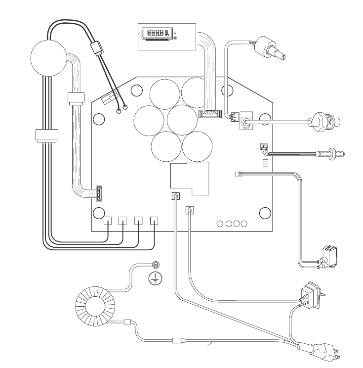
Wiring Diagram
Technical Data
Pressure
Transducer
Digital Display
ON/OFF
Switch
Power Plug
Black +
white
green/ground
Motor
green/ground
Potentiometer
Black
Black
Motor
Leads
Motor
Sensor
Leads
Thermal
Switch
1595 Switch
20A 15A
ti114889a
Power requirements 15A/20A
Motor HP (W) 2.5 (1864)
Maximum fluid working pressure 2500 psi (17.2 MPa, 172 bar)
Hopper capacity
Maximum 28 gallons (106 liters)
Operating 24 gallons (91 liters)
Maximum delivery with texture material 1.0 to 1.7 gpm (3.8 to 6.4 lpm)
Maximum hose length 150 ft of 1/2 in. hose
Fluid outlet size 1/2 in. NPT female swivel
Dimensions
Length 40 to 55 in. (102 cm to 140 cm) with handle
Width 22 in. (56 cm)
Height 31 in. (79 cm)
Weight
Without hoses or applicator 141 lb (64 kg)
With hoses and applicator 166 lb (75 kg)
Wetted parts Buna-N, aluminum, brass, polyethylene, neoprene, stainless steel, nickel-plated carbon steel, fluoro-
elastomer, nickel-plated iron, wool felt, tungsten carbide, PTFE, nylon, zinc-plated carbon steel, paper,
PVC, UHMWPE, leather, rubber
Sound data for sprayer
Sound pressure level *
Sound power level †
* Measured while spraying at 1 m.
† Measured per ISO-3744.

Warranty
18 3A0245A
Warranty
Graco warrants all equipment referenced in this document which is manufactured by Graco and bearing its name to be free from defects in
material and workmanship on the date of sale by an authorized Graco distributor to the original purchaser for use. With the exception of any
special, extended, or limited warranty published by Graco, Graco will, for a period of twelve months from the date of sale, repair or replace any part
of the equipment determined by Graco to be defective. This warranty applies only when the equipment is installed, operated and maintained in
accordance with Graco’s written recommendations.
This warranty does not cover, and Graco shall not be liable for general wear and tear, or any malfunction, damage or wear caused by faulty
installation, misapplication, abrasion, corrosion, inadequate or improper maintenance, negligence, accident, tampering, or substitution of
non-Graco component parts. Nor shall Graco be liable for malfunction, damage or wear caused by the incompatibility of Graco equipment
with structures, accessories, equipment or materials not supplied by Graco, or the improper design, manufacture, installation, operation or
maintenance of structures, accessories, equipment or materials not supplied by Graco.
This warranty is conditioned upon the prepaid return of the equipment claimed to be defective to an authorized Graco distributor for verification of
the claimed defect. If the claimed defect is verified, Graco will repair or replace free of charge any defective parts. The equipment will be returned
to the original purchaser transportation prepaid. If inspection of the equipment does not disclose any defect in material or workmanship, repairs will
be made at a reasonable charge, which charges may include the costs of parts, labor, and transportation.
THIS WARRANTY IS EXCLUSIVE, AND IS IN LIEU OF ANY OTHER WARRANTIES, EXPRESS OR IMPLIED, INCLUDING BUT NOT LIMITED
TO WARRANTY OF MERCHANTABILITY OR WARRANTY OF FITNESS FOR A PARTICULAR PURPOSE.
Graco’s sole obligation and buyer’s sole remedy for any breach of warranty shall be as set forth above. The buyer agrees that no other remedy
(including, but not limited to, incidental or consequential damages for lost profits, lost sales, injury to person or property, or any other incidental
or consequential loss) shall be available. Any action for breach of warranty must be brought within two (2) years of the date of sale.
GRACO MAKES NO WARRANTY, AND DISCLAIMS ALL IMPLIED WARRANTIES OF MERCHANTABILITY AND FITNESS FOR A
PARTICULAR PURPOSE, IN CONNECTION WITH ACCESSORIES, EQUIPMENT, MATERIALS OR COMPONENTS SOLD BUT NOT
MANUFACTURED BY GRACO. These items sold, but not manufactured by Graco (such as electric motors, switches, hose, etc.), are subject
to the warranty, if any, of their manufacturer. Graco will provide purchaser with reasonable assistance in making any claim for breach of these
warranties.
In no event will Graco be liable for indirect, incidental, special or consequential damages resulting from Graco supplying equipment hereunder,
or the furnishing, performance, or use of any products or other goods sold hereto, whether due to a breach of contract, breach of warranty, the
negligence of Graco, or otherwise.
FOR GRACO CANADA CUSTOMERS
The Parties acknowledge that they have required that the present document, as well as all documents, notices and legal proceedings entered into,
given or instituted pursuant hereto or relating directly or indirectly hereto, be drawn up in English. Les parties reconnaissent avoir convenu que la
rédaction du présent document ainsi que de tous les documents, avis et procédures judiciaires exécutés, donnés ou intentés à la suite de ou en
rapport, directement ou indirectement, avec les procédures concernées, sera en anglais.
ADDITIONAL WARRANTY COVERAGE
Graco does provide extended warranty and wear warranty for products described in the “Graco Contractor Equipment Warranty Program”.
3A0245A 19
TO PLACE AN ORDER, contact your Graco distributor, or call 1-800-690-2894 to identify the nearest distributor.
All written and visual data contained in this document reflects the latest product information available at the time of publication.
Graco reserves the right to make changes at any time without notice.
This manual contains English, French, Spanish, Dutch, German mm 313XXX
Graco Headquarters: Minneapolis
International Offices: Belgium, Korea, China, Japan
GRACO INC. P.O. BOX 1441 MINNEAPOLIS, MN 55440-1441
http://www.graco.com