Graco 309297L Pro Auto Xs Users Manual Xs, Automatic Electrostatic Air Spray Gun, Instructions/Parts, English
2015-04-02
: Graco Graco-309297L-Pro-Auto-Xs-Users-Manual-686487 graco-309297l-pro-auto-xs-users-manual-686487 graco pdf
Open the PDF directly: View PDF ![]() .
.
Page Count: 56
- List of Models
- Symbols
- Warning
- Introduction
- Installation
- Install the System
- Warning Signs
- Ventilate the Spray Booth
- Install the Air Line Accessories
- Install the Fluid Line Accessories
- Install the Gun and Mounting Bracket
- Connect the Air and Fluid Lines
- Manifold Connections
- Optional Fiber Optic Cable Connection
- Grounding
- Check Electrical Grounding
- Check Fluid Resistivity
- Check Fluid Viscosity
- Install the Fabric Cover
- 245324 HC Conversion Kit
- Operation
- Maintenance
- Electrical Tests
- Troubleshooting
- Repair
- Prepare the Gun for Service
- Remove the Gun from the Manifold
- Install the Gun on the Manifold
- Air Cap/Nozzle Replacement
- Electrode Replacement
- Fluid Packing Removal
- Packing Rod Repair
- Piston Repair
- Adjust the Actuator Arm
- Barrel Removal
- Barrel Installation
- Power Supply Removal and Replacement
- Turbine Alternator Removal and Replacement
- Parts
- Accessories
- Technical Data
- Graco Standard Warranty
100 psi (0.7 MPa, 7 bar) Maximum Air Inlet Pressure
100 psi (0.7 MPa, 7 bar) Maximum Working Fluid Pressure
For use in Class I, Div. I hazardous locations using Group D spray materials.
For use in Group II, Zone 1 areas using Group IIA spray materials.
For Professional Use ONLY.
U.S. Patent 7,226,004
Important Safety Instructions
Read all warnings and instructions in this manual.
Save these instructions.
See page 2 for Table of Contents and page 3 for
List of Models.
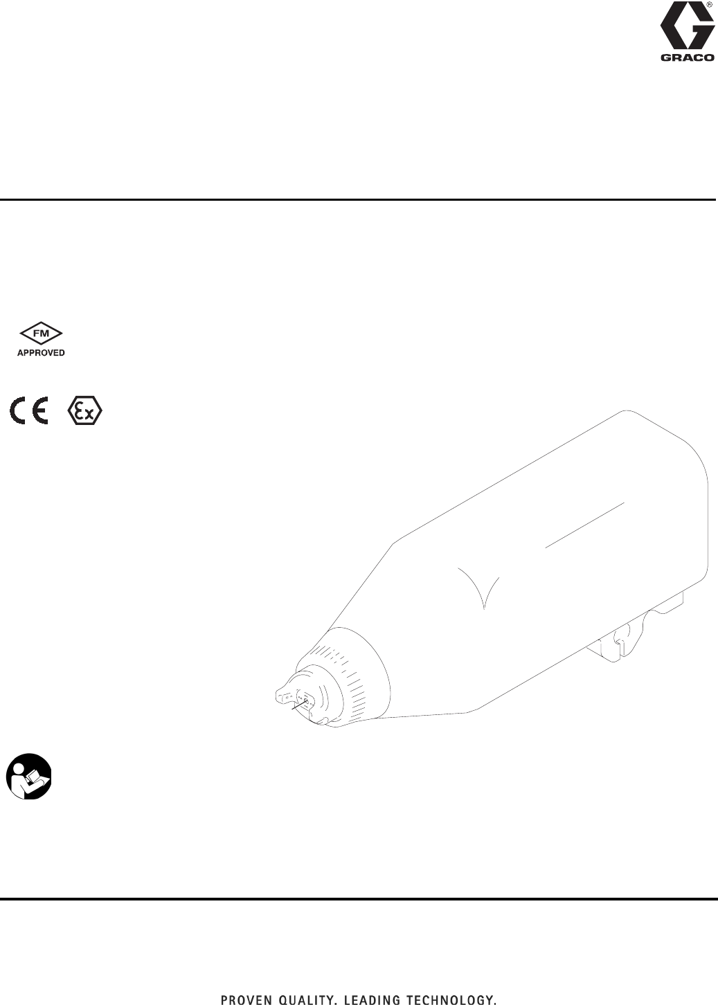
Instructions/Parts List
AUTOMATIC ELECTROSTATIC AIR SPRAY GUN
PRO
™
Auto Xs
TI1557A
#53
II 2 G EEx 0.24 mJ
309297L
EN
2309297L
Table of Contents
List of Models . . . . . . . . . . . . . . . . . . . . . . . . . . . . . 3
Symbols . . . . . . . . . . . . . . . . . . . . . . . . . . . . . . . . . . 3
Warning Symbol . . . . . . . . . . . . . . . . . . . . . . . . . 3
Caution Symbol . . . . . . . . . . . . . . . . . . . . . . . . . . 3
Warning . . . . . . . . . . . . . . . . . . . . . . . . . . . . . . . . . . 4
Introduction . . . . . . . . . . . . . . . . . . . . . . . . . . . . . . . 6
How the Electrostatic Air Spray Gun Works . . . . 6
Operating the Spray Function . . . . . . . . . . . . . . . 6
Operating the Electrostatics . . . . . . . . . . . . . . . . 6
Gun Features and Options . . . . . . . . . . . . . . . . . 6
Changing the kV Setting . . . . . . . . . . . . . . . . . . . 6
Installation . . . . . . . . . . . . . . . . . . . . . . . . . . . . . . . . 8
Install the System . . . . . . . . . . . . . . . . . . . . . . . . 8
Warning Signs . . . . . . . . . . . . . . . . . . . . . . . . . . . 8
Ventilate the Spray Booth . . . . . . . . . . . . . . . . . . 8
Install the Air Line Accessories . . . . . . . . . . . . . 10
Install the Fluid Line Accessories . . . . . . . . . . . 10
Install the Gun and Mounting Bracket . . . . . . . . 10
Connect the Air and Fluid Lines . . . . . . . . . . . . 11
Manifold Connections . . . . . . . . . . . . . . . . . . . . 11
Optional Fiber Optic Cable Connection . . . . . . 12
Grounding . . . . . . . . . . . . . . . . . . . . . . . . . . . . . 13
Check Electrical Grounding . . . . . . . . . . . . . . . 14
Check Fluid Resistivity . . . . . . . . . . . . . . . . . . . 15
Check Fluid Viscosity . . . . . . . . . . . . . . . . . . . . 15
Install the Fabric Cover . . . . . . . . . . . . . . . . . . . 15
245324 HC Conversion Kit . . . . . . . . . . . . . . . . 16
Operation . . . . . . . . . . . . . . . . . . . . . . . . . . . . . . . . 17
Pressure Relief Procedure . . . . . . . . . . . . . . . . 17
Operating Checklist . . . . . . . . . . . . . . . . . . . . . . 18
Select a Fluid Nozzle and Air Cap . . . . . . . . . . 18
Adjust the Spray Pattern . . . . . . . . . . . . . . . . . . 19
Adjust the Electrostatics . . . . . . . . . . . . . . . . . . 20
Spraying . . . . . . . . . . . . . . . . . . . . . . . . . . . . . . 21
Triggering the Fluid Alone . . . . . . . . . . . . . . . . . 21
Shutdown . . . . . . . . . . . . . . . . . . . . . . . . . . . . . 21
Maintenance . . . . . . . . . . . . . . . . . . . . . . . . . . . . . . 22
Daily Care and Cleaning . . . . . . . . . . . . . . . . . . 22
Clean the Air Cap and Fluid Nozzle . . . . . . . . . 24
Check for Fluid Leakage . . . . . . . . . . . . . . . . . . 25
Electrical Tests . . . . . . . . . . . . . . . . . . . . . . . . . . . . 26
Test Gun Resistance . . . . . . . . . . . . . . . . . . . . . 26
Test Power Supply Resistance . . . . . . . . . . . . . 27
Test Electrode Resistance . . . . . . . . . . . . . . . . . 28
Troubleshooting . . . . . . . . . . . . . . . . . . . . . . . . . . . 29
Spray Pattern Troubleshooting . . . . . . . . . . . . . 29
Gun Operation Troubleshooting . . . . . . . . . . . . 30
Electrical Troubleshooting . . . . . . . . . . . . . . . . . 31
Repair . . . . . . . . . . . . . . . . . . . . . . . . . . . . . . . . . . . 32
Prepare the Gun for Service . . . . . . . . . . . . . . . 32
Remove the Gun from the Manifold . . . . . . . . . . 33
Install the Gun on the Manifold . . . . . . . . . . . . . 33
Air Cap/Nozzle Replacement . . . . . . . . . . . . . . 34
Electrode Replacement . . . . . . . . . . . . . . . . . . . 35
Fluid Packing Removal . . . . . . . . . . . . . . . . . . . 36
Packing Rod Repair . . . . . . . . . . . . . . . . . . . . . . 37
Piston Repair . . . . . . . . . . . . . . . . . . . . . . . . . . . 38
Adjust the Actuator Arm . . . . . . . . . . . . . . . . . . . 39
Barrel Removal . . . . . . . . . . . . . . . . . . . . . . . . . 40
Barrel Installation . . . . . . . . . . . . . . . . . . . . . . . . 41
Power Supply Removal and Replacement . . . . 42
Turbine Alternator Removal and Replacement . 43
Parts . . . . . . . . . . . . . . . . . . . . . . . . . . . . . . . . . . . . 45
Accessories . . . . . . . . . . . . . . . . . . . . . . . . . . . . . . 52
Air Line Accessories . . . . . . . . . . . . . . . . . . . . . 52
Fluid Line Accessories . . . . . . . . . . . . . . . . . . . . 52
Miscellaneous Accessories . . . . . . . . . . . . . . . . 53
Gun Accessories . . . . . . . . . . . . . . . . . . . . . . . . 54
Technical Data . . . . . . . . . . . . . . . . . . . . . . . . . . . . 55
Graco Standard Warranty . . . . . . . . . . . . . . . . . . . 56

List of Models
309297L 3
List of Models
Symbols
Warning Symbol
This symbol alerts you to the possibility of serious injury
or death if you do not follow the instructions.
Caution Symbol
This symbol alerts you to the possibility of damage to or
destruction of equipment if you do not follow the instruc-
tions.
Part No. Model Voltage
Type of Coatings
Standard High Conductivity
244589 PRO Auto Xs 40-85 kV X
244590 PRO Auto Xs 40-85 kV X
WARNING CAUTION
Warning
4309297L
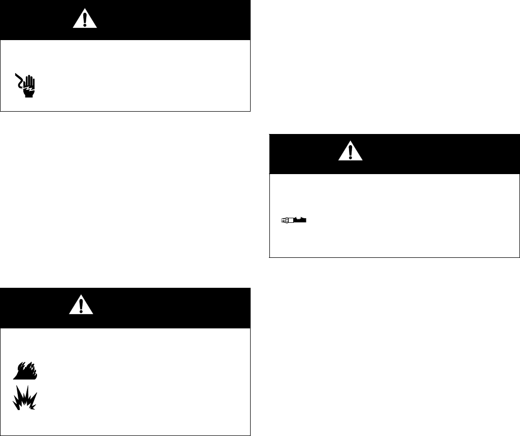
WARNING
Fire, Explosion, and Electric Shock Hazard
Flammable fumes, such as solvent and paint fumes, in work area can ignite or explode. To help
prevent fire and explosion:
•Electrostatic equipment must be used only by trained, qualified personnel who understand the
requirements of this manual.
•Ground equipment, personnel, object being sprayed, and conductive objects in work area. See
Grounding instructions.
•Only use grounded Graco conductive air supply hoses.
•Check gun and hose resistance and electrical grounding daily.
•Use and clean equipment only in well ventilated area.
•Interlock the gun air supply to prevent operation unless ventilating fans are on.
•Use cleaning solvents with highest possible flash point when flushing or cleaning equipment.
To comply with EN50050 requirements, cleaning solvents must have a flash point at least 5°C
above ambient temperature.
•Always turn the electrostatics off when flushing, cleaning or servicing equipment.
•If there is static sparking or you feel a shock, stop operation immediately. Do not use equip-
ment until you identify and correct the problem.
•Eliminate all ignition sources; such as pilot lights, cigarettes, portable electric lamps, and plas-
tic drop cloths (potential static arc).
•Do not plug or unplug power cords or turn lights on or off when flammable fumes are present.
•Keep work area free of debris, including solvent, rags and gasoline.
•Keep a working fire extinguisher in the work area.
Toxic Fluid Hazard
Hazardous fluids or toxic fumes can cause a serious injury or death if splashed in the eyes or on
the skin, swallowed, or inhaled.
•Know the specific hazards of the fluid you are using. Read the fluid manufacturer’s warnings.
•Store hazardous fluid in an approved container. Dispose of the hazardous fluid according to all
local, state, and national guidelines.
•Wear appropriate protective clothing, gloves, eyewear, and respirator.
Warning
309297L 5
WARNING
Equipment Misuse Hazard
Equipment misuse can cause the equipment to rupture, malfunction, or start unexpectedly and
result in a serious injury.
•This equipment is for professional use only.
•Read all manuals, tags, and labels before operating the equipment.
•Use the equipment only for its intended purpose. If you are uncertain, call your Graco distribu-
tor.
•Do not alter or modify equipment. Use only genuine Graco parts and accessories.
•Check the equipment daily. Repair or replace worn or damaged parts immediately.
•Do not exceed the maximum working pressure of the lowest rated system component. Maxi-
mum working air and fluid pressure of this equipment is 100 psi (0.7 MPa, 7.0 bar).
•Use fluids and solvents that are compatible with the equipment wetted parts. See the Techni-
cal Data section of all equipment manuals. Read the fluid and solvent manufacturer’s warn-
ings.
•Route the hoses away from traffic areas, sharp edges, moving parts, and hot surfaces. Do not
expose Graco hoses to temperatures above 180°F (82°C) or below -40°F (-40°C).
•Wear hearing protection when operating this equipment.
•Comply with all applicable local, state, and national fire, electrical, and other safety regula-
tions.
Pressurized Equipment Hazard
Spray from the gun, hose leaks, or ruptured components can splash fluid in the eyes or on the skin
and cause serious injury.
•Do not point the spray gun at anyone or at any part of the body.
•Do not stop or deflect fluid leaks with your hand, body, glove, or rag.
•Follow the steps under Prepare the Gun for Service, page 32, when you stop spraying and
before cleaning, checking, or repairing equipment.
•Check hoses and couplings daily. Replace worn, damaged, or loose parts immediately.
•Tighten all fluid connections before each use.

Introduction
6309297L
Introduction
How the Electrostatic Air
Spray Gun Works
The automatic electrostatic air spray gun operates very
similar to a traditional air spray gun. The atomization
and fan air are emitted from the air cap. The atomization
air breaks up the fluid stream and controls the droplet
size. The fan air controls the shape and width of the
spray pattern. The fan and atomization air can be
adjusted independently.
Operating the Spray
Function
Applying a minimum of 50 psi (0.35 MPa, 3.5 bar) air
pressure to the gun manifold’s cylinder air fitting (CYL)
will retract the gun piston, which opens the air valves
and a short time later opens the fluid needle. This pro-
vides the proper air lead and lag when triggering the
gun. A spring returns the piston when the cylinder air is
shut off.
Operating the Electrostatics
To operate the electrostatics, apply air pressure to the
gun manifold’s turbine air fitting (TA) through a Graco
grounded air hose. The air enters the manifold and is
directed to the inlet of the power supply turbine. The air
spins the turbine, which then provides electrical power
to the internal high voltage power supply. The fluid is
charged by the spray gun electrode. The charged fluid is
attracted to the nearest grounded object, wrapping
around and evenly coating all surfaces.
The turbine air is exhausted into the shroud and out the
back of the manifold through the exhaust fitting (EXH).
The exhaust air helps keep contaminants out and helps
keep the gun clean.
Gun Features and Options
•The gun is designed for use with a reciprocator, and
can be mounted directly on a 1/2 in. (13 mm) rod.
With additional brackets, the gun can be mounted
for robotic applications.
•The gun’s quick-disconnect design enables its
removal without disconnecting the fluid and air lines
to the gun.
•Gun functions are activated from a separate control-
ler that sends the appropriate signal to the actuating
solenoids.
•The optional fiber optic readout system can be
installed to monitor the gun’s spraying voltage. A
fiber optic cable connected to the gun manifold car-
ries the signal from the gun to a remote display
module. Part No. 224117 Display Module displays
the gun’s spraying voltage and current. Bat-
tery-operated Display Module 189762 displays the
gun’s spraying voltage only.
Changing the kV Setting
The gun’s full voltage setting is 85 kV. Three lower volt-
age settings are possible by actuating the KV1 and KV2
switches. Supply 50 psi (0.35 MPa, 3.5 bar) air pressure
to the KV1 and KV2 ports. Turn the air on or off as
shown in Table 1 to set the desired voltage.
The solenoid valves used to activate the KV1 and KV2
switches must bleed the air out of the lines for the
switches to draw back to the higher voltage setting.
Table 1: KV1 and KV2 Switch Settings
KV1 Air KV2 Air Output Voltage (kV)
OFF OFF 85
OFF ON 70
ON OFF 60
ON ON 45
Introduction
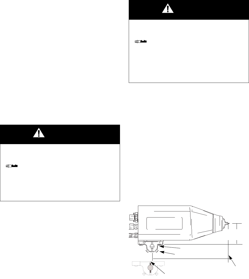
309297L 7
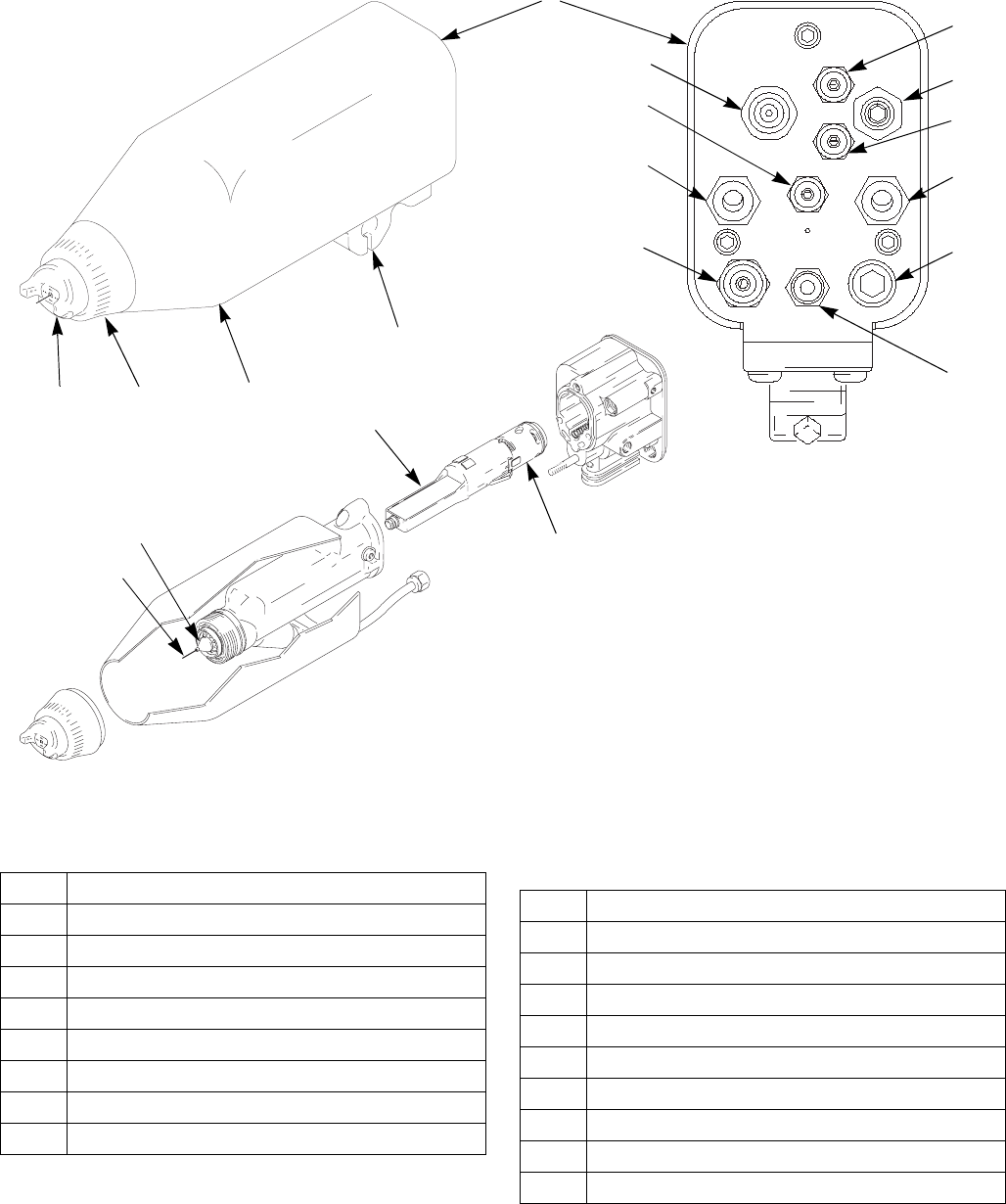
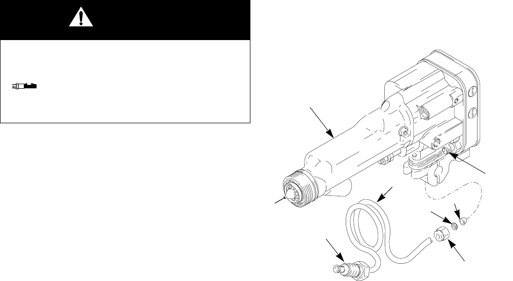
Fig. 1: Gun Overview
Key
TI1577A
TI1561A
TI1557A
Manifold Back View
A
B
CD
E
F
G
H
J
A1 A2
CYL
EXH
FO
KV2
P1 P2
TA
KV1
AAir Cap
B Fluid Nozzle
C Retaining Ring
D Shroud
E Mounting Bracket
FManifold
G Turbine
H Power Supply
J Electrode
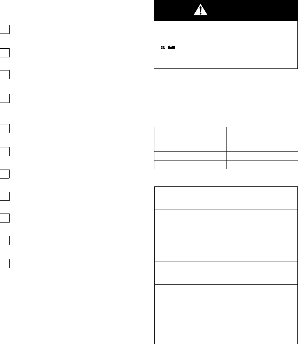
Manifold Markings
A1 Atomization Air Inlet Fitting
A2 Fan Air Inlet Fitting
CYL Cylinder Air Inlet Fitting
EXH Shroud Exhaust Outlet Fitting
FO Fiber Optic Fitting (shipped unassembled)
KV1 kV Switch 1 Air Inlet
KV2 kV Switch 2 Air Inlet
P1 Fluid Supply Inlet Fitting
P2 Fluid Return Inlet Fitting (optional)
TA Turbine Air Inlet Fitting
Installation
8309297L
Installation
Install the System
F
IGURE
2 shows a typical electrostatic air spray system,
and F
IGURE
3 shows possible system options. It is not
an actual system design. For assistance in designing a
system to suit your particular needs, contact your Graco
distributor.
Warning Signs
Mount warning signs in the spray area where they can
easily be seen and read by all operators. An English
Warning Sign is provided with the gun.
Ventilate the Spray Booth
Electrically interlock the gun turbine air supply (B) with
the ventilators to prevent gun operation without ventilat-
ing fans operating. Check and follow all National, State,
and Local codes regarding air exhaust velocity require-
ments.
High velocity air exhaust will decrease the operating effi-
ciency of the electrostatic system. The minimum allow-
able air exhaust velocity is 60 ft/minute (19 linear
meters/minute).
Key to F
IGURE
2 and F
IGURE
3
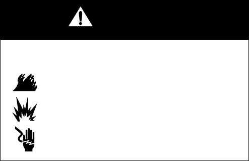
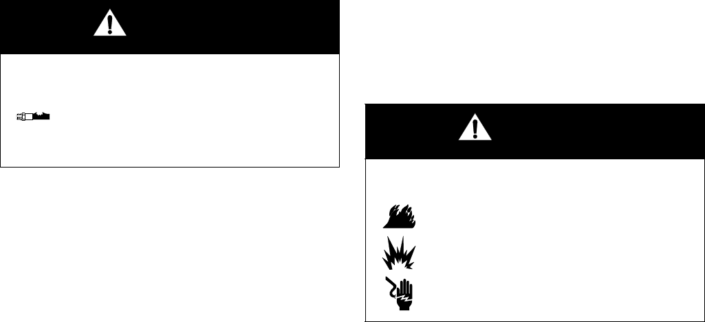
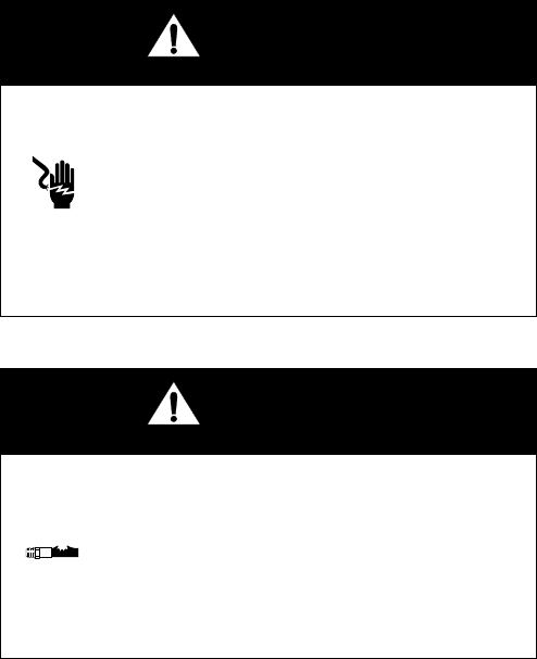
WARNING
Fire, Explosion, and Electric Shock Hazard
Installing and servicing this equipment
requires access to parts which may cause
electric shock or other serious injury if work
is not performed properly.
•Do not install or service this equipment
unless you are trained and qualified.
•Be sure your installation complies with
National, State and Local codes for the
installation of electrical apparatus in a Class
I, Div. I, Group D or a Group II,
Category 2G Hazardous Location.
•Comply with all applicable local, state, and
national fire, electrical, and other safety regula-
tions.
WARNING
Flammable or Toxic Vapor Hazard
Provide fresh air ventilation to avoid the buildup of
flammable or toxic vapors when spraying, flushing, or
cleaning the gun. Do not operate the gun unless ven-
tilation fans are operating.
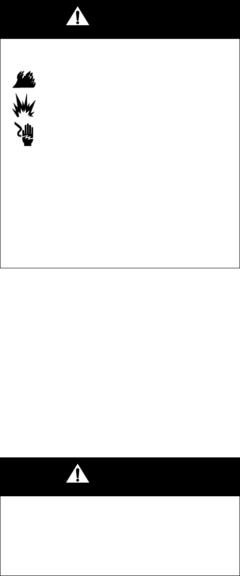
A Air Hose Ground Wire
B Graco Grounded Turbine Air Hose (TA)
C Atomizing Air Hose, 3/8 in. (10 mm) OD (A1)
D Fan Air Hose, 3/8 in. (10 mm) OD (A2)
E Cylinder Air Hose, 5/32 in. (4 mm) OD (CYL)
F Fluid Hose, 1/4-18 npsm gun fluid inlet (P1)
G To Fluid Supply
H Auto PRO Xs Air Spray Gun
J Mounting Bracket for 1/2 in. (13 mm) rod
K Solenoid Valve, requires quick exhaust port
L Bleed-Type Master Air Valve
M Air Pressure Regulator
N True Earth Ground
P 24 Volt Power Supply
Q 4-20 microampere Outputs
R Full Feature ES Display Module
S kV Only ES Display Module (battery operated)
T Fiber Optic Y Cable
U Bulkhead
V Fiber Optic Cable
W Main Air Line
XkV Switch Air Hose, 5/32 in. (4 mm) OD (optional; plug KV1
fitting if not used)
YkV Switch Air Hose, 5/32 in. (4 mm) OD (optional; plug KV2
fitting if not used)
Installation
309297L 9
Fig. 2: Typical Installation
Fig. 3: Optional Fiber Optic Connection to Voltage Display Module
TI1712A
A
BCD
EF
J
K
M
N
G
NOTE:
* The turbine air supply (TA) must be electrically interlocked with the spray booth ventilation fans to prevent
the power supply from operating without ventilating fans on.
Non-Hazardous Area Hazardous Area
Y
W
P1
CYL
A2A1
KV2
TA
K
K
See *
above
K
X
KV1
L
L
L
Manifold Back View
TI1583A
KV
μA
85.0 KV
Q
T
NOTE:
** A maximum of two splices with a total of 108 ft (33 m) of cable can be used. For the stron-
gest light signals, use a minimum number of bulkhead splices. See Accessories on page 53.
Non-Hazardous Area Hazardous Area
H
U**R
P
S
V**
Installation
10 309297L
Install the Air Line
Accessories
1. Install a bleed-type air valve (L) on the main air line
(W) to shut off all air to the gun (H).
2. Install an air line filter/water separator on the gun air
line to ensure a dry, clean air supply to the gun. Dirt
and moisture can ruin the appearance of your fin-
ished workpiece and can cause the gun to malfunc-
tion.
3. Install a bleed-type air regulator (M) on each of the
air supply lines (B, C, D, E, X, Y) to control air pres-
sure to the gun.
4. Install a solenoid valve (K) on the cylinder air line
(E) to actuate the gun. The solenoid valve must
have a quick exhaust port.
Install the Fluid Line
Accessories
1. Install a fluid filter and drain valve at the pump out-
let.
2. Install a fluid regulator on the fluid line to control
fluid pressure to the gun.
Install the Gun and Mounting
Bracket
1. Loosen the mounting bracket’s two set screws (103)
and slide the bracket (102) onto a 1/2 in. (13 mm)
mounting rod. See F
IGURE
4.
2. Position the gun and tighten the two set screws.
For added positioning reliability, insert a 1/8 in. (3 mm)
locating pin into the slot (NN) in the bracket and through
a hole in the rod. See the detail in F
IGURE
4.
Fig. 4: Mounting Bracket
WARNING
Pressurized Equipment Hazard
Trapped air can cause the gun to spray
unexpectedly, which can result in serious
injury, including splashing fluid in the eyes
or on the skin. The solenoid valves (K) must
have a quick exhaust port so trapped air will
be relieved between the valve and gun
when the solenoids are shut off.
WARNING
Pressurized Equipment Hazard
The fluid drain valve is required in your sys-
tem to assist in relieving fluid pressure in
the displacement pump, hose, and gun.
Triggering the gun to relieve pressure may
not be sufficient. Install a drain valve close
to the pump's fluid outlet. The drain valve
reduces the risk of serious injury, including
splashing in the eyes or on the skin.
TI1570A
103
102
NN
03460
9.22 in
(234.2 mm)
2.88 in
(73.2 mm)
To nozzle tip
Installation
309297L 11
Connect the Air and Fluid
Lines
F
IGURE
3 shows a schematic of air and fluid line connec-
tions, and F
IGURE
5 shows the manifold connections.
Connect the air and fluid lines as instructed.
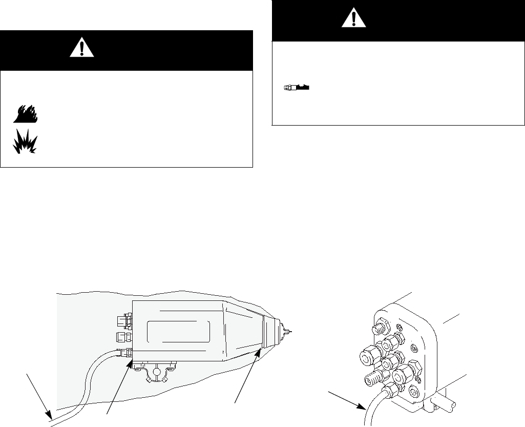
1. Connect the Graco Grounded Air Supply Hose (B)
to the gun's turbine air inlet (TA) and connect the
hose ground wire (A) to a true earth ground (N). The
gun turbine air inlet fitting has left-hand threads to
prevent connecting another type of air hose to the
turbine air inlet. See Accessories on page 52 for
further information about the hose.
2. Check the electrical grounding of the gun as
instructed on page 14.
3. Before connecting the fluid line (P1), blow it out with
air and flush it with solvent. Use solvent which is
compatible with the fluid to be sprayed.
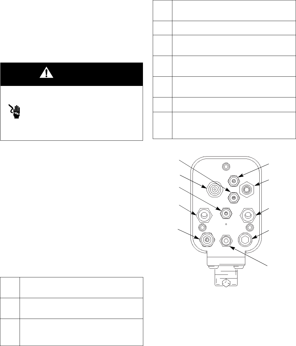
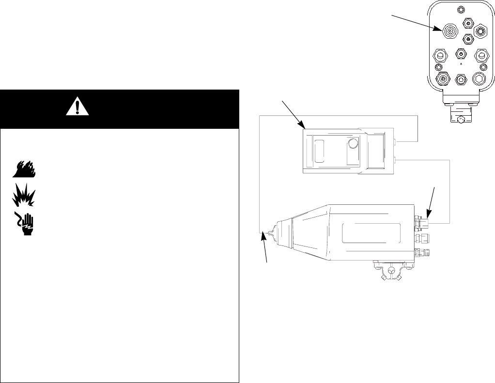
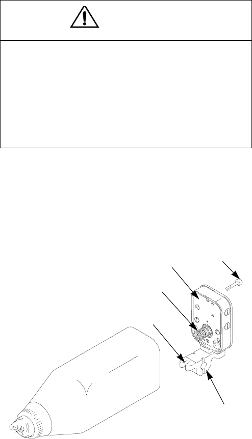
Manifold Connections
Fig. 5: Manifold Connections
WARNING
Electric Shock Hazard
To reduce the risk of electric shock or other
serious injury, the turbine air supply hose
must be electrically connected to a true
earth ground. Use only Graco Grounded
Air Supply Hose.
A1 Atomization Air Inlet Fitting
Connect a 3/8 in. (10 mm) OD tube between this fitting and
the air supply.
A2 Fan Air Inlet Fitting
Connect a 3/8 in. (10 mm) OD tube between this fitting and
the air supply.
CYL Cylinder Air Inlet Fitting
Connect a 5/32 in. (4 mm) OD tube between this fitting and
the solenoid. For quicker response, use the shortest hose
length possible.
EXH Shroud Exhaust Outlet Fitting
Connect a 1/4 in. (6 mm) OD x 4 ft (1.22 m) long tube to
this fitting.
FO Fiber Optic Fitting (Optional)
Connect the Graco Fiber Optic cable (see page 11).
KV1 kV Switch 1 Air Inlet Fitting
Connect a 5/32 in. (4 mm) OD tube between this fitting and
the solenoid.
KV2 kV Switch 2 Air Inlet Fitting
Connect a 5/32 in. (4 mm) OD tube between this fitting and
the solenoid.
P1 Fluid Supply Inlet Fitting
Connect a 1/4 npsm swivel fitting between this fitting and
the fluid supply.
P2 Fluid Return Inlet Fitting (optional)
Order Part No. 233676 Fluid Recirculation Kit.
TA Turbine Air Inlet Fitting
Connect the Graco Electrically Conductive Air Hose
between this fitting (left-hand thread) and the solenoid.
Connect the air hose ground wire to a true earth ground.
TI1577A
A1 A2
CYL
EXH
FO
KV2
P1 P2
TA
KV1
Installation
12 309297L
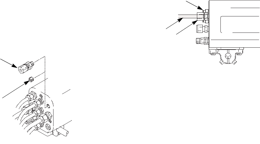
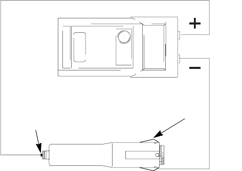
Optional Fiber Optic Cable
Connection
An optional fiber optic fitting is shipped unassembled
with the gun. If an ES (kV) display module is used,
install the fitting in the FO port of the manifold. See F
IG
-
URE
3, page 9, for a schematic of the fiber optic connec-
tions.
1. Remove the plug (120) from the fiber optic port, and
install the fiber optic fitting (5, shipped loose with the
gun). See F
IGURE
6.
Fig. 6: Fiber Optic Fitting
2. Remove the nut (AA) from the fiber optic fitting (5)
and slide the nut over the end of the fiber optic cable
(BB). See F
IGURE
7.
3. Push the cable (BB) into the fitting (5) until it bot-
toms out. Tighten the nut (AA) to secure the cable.
Fig. 7: Fiber Optic Cable
Most of the fiber optic light transmission loss occurs at
the bulkhead splices. For the strongest light signals, use
a minimum number of bulkhead splices. A maximum of
two splices, with a total of 108 ft (33 m) of cable, is rec-
ommended.
4. See manual 308265 to install a Graco ES Display
Module.
TI1580A
120
5
TI1581A
AA
5
BB
Installation
309297L 13
Grounding
The following are minimum grounding requirements for
a basic electrostatic system. Your system may include
other equipment or objects which must be grounded.
Check your local electrical code for detailed grounding
instructions. Your system must be connected to a true
earth ground.
•
Pump:
ground the pump by connecting a ground
wire and clamp as described in your separate pump
instruction manual.
•
Electrostatic Air Spray Gun:
ground the gun by con-
necting the Graco Grounded Air Hose to the turbine
air inlet and connecting the air hose ground wire to a
true earth ground. See Check Electrical Ground-
ing, page 14.
•
Air compressors and hydraulic power supplies:
ground the equipment according to the manufac-
turer's recommendations.
•
All air and fluid lines
must be properly grounded.
•
All electrical cables
must be properly grounded.
•
All persons entering the spray area:
shoes must
have conductive soles, such as leather, or personal
grounding straps must be worn. Do not wear shoes
with non-conductive soles such as rubber or plastic.
•
Object being sprayed:
keep the workpiece hangers
clean and grounded at all times. Resistance must
not exceed 1 megohm.
•
The floor of the spray area:
must be electrically con-
ductive and grounded. Do not cover the floor with
cardboard or any non-conductive material which
would interrupt grounding continuity.
•
Flammable liquids in the spray area:
must be kept in
approved, grounded containers. Do not use plastic
containers. Do not store more than the quantity
needed for one shift.
•
All electrically conductive objects or devices in the
spray area:
including fluid containers and wash
cans, must be properly grounded.
WARNING
Fire, Explosion, and Electric Shock Hazard
When operating the electrostatic gun, any
ungrounded objects in the spray area (peo-
ple, containers, tools, etc.) can become
electrically charged. Improper grounding
can result in static sparking, which can
cause a fire, explosion, or electric shock.
Follow the grounding instructions below.
Installation
14 309297L
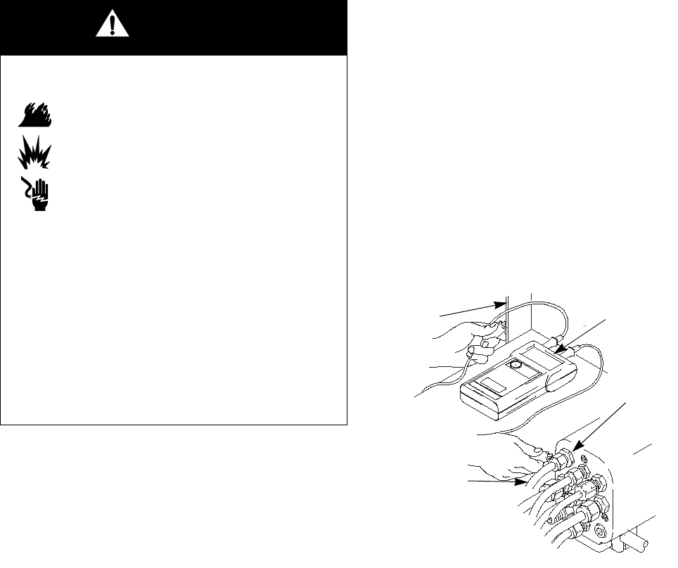
Check Electrical Grounding
1. Have a qualified electrician check the electrical
grounding continuity of the spray gun and turbine air
hose.
2. Make sure the turbine air hose (B) is connected and
the hose ground wire is connected to a true earth
ground.
3. Turn off the air and fluid supply to the gun. The fluid
hose must not have any fluid in it.
4. Measure the resistance between the turbine air inlet
fitting (TA) and a true earth ground (N).
a.
If using a black or grey turbine air hose,
use a
megohmmeter to measure the resistance. Use
an applied voltage of 500 minimum to 1000
volts maximum. The resistance should not
exceed 1 megohm.
b.
If using a red turbine air hose,
use an ohmmeter
to measure the resistance. The resistance
should not exceed 100 ohms.
3. If the resistance is greater than the maximum read-
ing specified above for your hose, check the tight-
ness of the ground connections and be sure the
turbine air hose ground wire is connected to a true
earth ground. If the resistance is still too high,
replace the turbine air hose.
Fig. 8. Check Gun Grounding
WARNING
Fire, Explosion, and Electric Shock Hazard
Megohmmeter Part No. 241079 (AA-see
F
IGURE
8) is not approved for use in a haz-
ardous area. To reduce the risk of sparking,
do not use the megohmmeter to check
electrical grounding unless:
•The gun has been removed from the
hazardous area;
•Or all spraying devices in the hazardous
area are turned off, ventilation fans in the
hazardous area are operating, and there
are no flammable vapors in the area
(such as open solvent containers or
fumes from spraying).
Failure to follow this warning could cause
fire, explosion, and electric shock and result
in serious injury and property damage.
TI1584
A
B
AA
TA
N
Installation
309297L 15
Check Fluid Resistivity
Graco Part No. 722886 Resistance Meter and 722860
Probe are available as accessories to check that the
resistivity of the fluid being sprayed meets the require-
ments of an electrostatic air spray system.
Follow the instructions included with the meter and
probe. Readings of 25 megohms-cm and above provide
the best electrostatic results.
Check Fluid Viscosity
To check fluid viscosity you will need:
•a viscosity cup
•a stopwatch.
1. Completely submerge the viscosity cup in the fluid.
Lift the cup out quickly, starting the stopwatch as
soon as the cup is completely removed.
2. Watch the stream of fluid coming from the bottom of
the cup. As soon as there is a break in the stream,
shut off the stopwatch.
3. Record the fluid type, elapsed time, and size of the
viscosity cup.
4. If the viscosity is too high or too low, contact the
material supplier. Adjust as necessary.
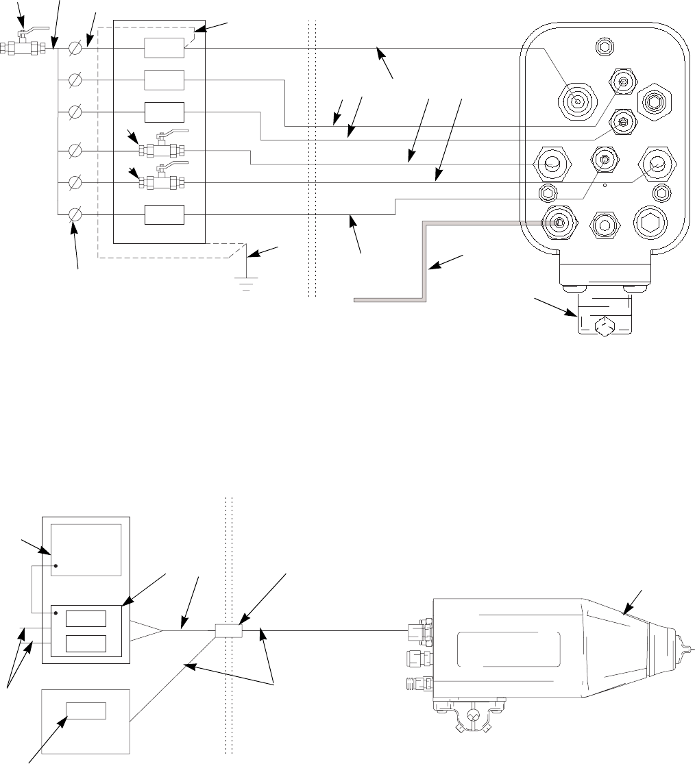
Install the Fabric Cover
1. Install a fabric cover (XX) over the front of the gun
and slide it back to cover the exposed tubing and
hoses at the back of the manifold. See F
IGURE
9.
2. Route the exhaust tube (YY) outside the cover. This
enables you to monitor the exhaust tube for the
presence of any paint or solvent. See Check for
Fluid Leakage on page 25. Strap down the exhaust
tube to prevent it from moving around.
Fig. 9. Fabric Cover
WARNING
Fire, Explosion, and Electric Shock Hazard
Check the fluid resistivity in a non-hazard-
ous area only. Resistance Meter 722886
and Probe 722860 are not approved for use
in a hazardous area.
Failure to follow this warning could cause
fire, explosion, or electric shock and result
in serious injury and property damage.
ti1571a
TI1579A
YY
YY
XX
Installation
16 309297L
245324 HC Conversion Kit
Part No. 245324 Conversion Kit is available to convert
PRO Auto Xs standard coating guns (Part No. 244589)
to high conductivity guns (244590).
The kit is for use with fluids with low resistivity values.
1. Turn the turbine air (TA) off.
2. Flush the gun.
3. Relieve the pressure.
4. Remove the retaining ring (1), air cap (3), and
shroud (2).
5. Refer to the parts drawing for Model 244589 on
page 45. Loosen the two nuts (20) and remove the
fluid tube (19) and ferrules (21, 22). Remove the
other parts (14, 15, 16, 17, 18) at the gun barrel
inlet.
6. Slide the loops of the hc tube (19) onto the gun bar-
rel (9).
7. Make sure the barrel threads are clean and dry.
Apply Graco Part No. 116553 dielectric grease to
the fluid fitting (19d) threads and o-rings. Thread
the fitting into the barrel inlet. See F
IGURE
10.
8. Slide the nut (20) and ferrules (21, 22) onto the
coiled tube (19). Insert the end of the tube into the
fitting (23). Make sure the ferrules seat in the fitting.
Tighten the nut (20).
Fig. 10. HC Conversion Kit
WARNING
Pressurized Equipment Hazard
To reduce the risk of an injury, follow the
Pressure Relief Procedure on page 17
before installing this kit.
TI1731A
23
19
9
19d
20
21
22
Operation
309297L 17
Operation
Pressure Relief Procedure
1. Turn off all the air to the spray gun except the cylin-
der air, which triggers the gun. If an air pilot fluid
regulator is used in the system, the air pressure is
needed at the regulator air inlet.
2. Turn off the fluid supply to the gun.
3. Trigger the gun into a grounded metal waste con-
tainer to relieve the fluid pressure.
4. If an air pilot fluid regulator is used, turn off the air
pressure at the regulator air inlet.
5. Relieve fluid pressure in the fluid supply equipment
as instructed in its instruction manual.
6. Turn off the main air supply by closing the
bleed-type master air valve on the main air supply
line. Leave the valve closed until you are ready to
spray again.
WARNING
Pressurized Equipment Hazard
The system pressure must be manually
relieved to prevent the system from starting
or spraying accidentally. To reduce the risk
of an injury from electric shock, accidental spray from
the gun, splashing fluid, or moving parts, follow the
Pressure Relief Procedure whenever you:
•are instructed to relieve the pressure
•stop spraying
•check or service any of the system equipment
•or install or clean the fluid nozzle.
Operation
18 309297L
Operating Checklist
Check the following list daily, before starting to operate
the system, to help ensure you of safe, efficient opera-
tion.
Select a Fluid Nozzle and Air
Cap
The gun is supplied with Part No. 197266 Nozzle and
24A438 Air Cap. If you require a different size, refer to
Table 2 and Table 3 , and instruction manual 309419, or
consult with your Graco distributor. See Air Cap/Nozzle
Replacement on page 34.
*Also available in the following colors: 24A276 - blue,
24A277 - red, 24A278 - green
All operators are properly trained to safely
operate an automatic electrostatic air spray
system as instructed in this manual.
All operators are trained in the Pressure
Relief Procedure on page 17.
The warning sign provided with the gun is
mounted in the spray area where it can be
easily seen and read by all operators.
The system is thoroughly grounded and the
operator and all persons entering the spray
area are properly grounded. See Grounding
on page 13.
The condition of the gun’s electrical compo-
nents has been checked as instructed in Elec-
trical Tests on page 26.
Ventilation fans are operating properly.
Workpiece hangers are clean and grounded.
All debris, including flammable fluids and rags,
is removed from the spray area.
All flammable fluids in the spray booth are in
approved, grounded containers.
All conductive objects in the spray area are
electrically grounded and the floor of the spray
area is electrically conductive and grounded.
The manifold exhaust tubes have been
checked for the presence of any fluid as
instructed in Check for Fluid Leakage on
page 25.
WARNING
Pressurized Equipment Hazard
To reduce the risk of an injury, follow the
Pressure Relief Procedure on page 17
before removing or installing a fluid nozzle
and/or air cap.
Table 2: Fluid Nozzles
Part No. Size,
mm (in.) Part No. Size,
mm (in.)
197263 0.75 (.030) 197266 1.5 (.055)
197264 1.0 (.042) 197267 1.8 (.070)
197265 1.2 (.047) 197268 2.0 (.080)
Table 3: Air Caps
Part No.
Pattern Shape
and Length in.
(mm)
Recommended Fluids and
Production Rates
24A438 Round end;
15-17 (381-432)
Light to medium viscosity.
Up to 15 oz/min (450
cc/min)
24A279 Round end;
14-16 (356-406)
Medium to high viscosity
and high solids.
Up to 15 oz/min (450
cc/min)
24A376* Tapered end;
17-19 (432-483)
Light to medium viscosity.
Up to 15 oz/min (450
cc/min)
24A274 Tapered end;
12-14 (305-356)
Light to medium viscosity.
Up to 15 oz/min (450
cc/min)
24A439 Round end;
11-13 (279-330)
Medium to high viscosity
and high solids.
Up to 15 oz/min (450
cc/min)
For use with 2.0 mm nozzle.
Operation
309297L 19
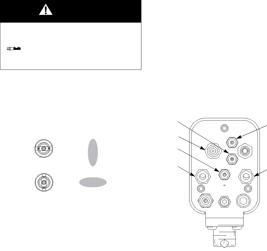
Adjust the Spray Pattern
Follow the steps below to establish the correct fluid flow
and air flow. Do not turn on the turbine air (TA) yet.
1. Relieve the pressure.
2. Loosen the air cap retaining ring, and rotate the air
cap for a vertical or horizontal spray pattern. See
F
IGURE
11. Tighten the retaining ring until the air cap
is held firmly in place; you should not be able to
rotate the air cap horns by hand.
Fig. 11. Air Cap Positions
3. Adjust the fluid flow with the fluid pressure regulator.
Refer to instruction manual 309419 to set the fluid
pressure for various fluid flows, according to the
size of the fluid nozzle being used.
4. Use the air pressure regulator on the atomization air
supply line (A1) to adjust the degree of atomization.
See F
IGURE
12. For example, for a fluid flow rate of
10 ounces per minute (0.3 liters per minute), a typi-
cal atomization pressure would be 20-30 psi
(1.4-2.1 bar, 0.14-0.21 MPa) at the gun manifold.
5. Use the air pressure regulator on the fan air supply
line (A2) to adjust the pattern size.
•For the most efficiency, always use the lowest air
pressure possible.
•When increasing to a wide, flat pattern, it may be
necessary to increase the supply of fluid to the gun
to maintain the same amount of coverage over a
large area.
•See Spray Pattern Troubleshooting on page 29 to
correct spray pattern problems.
Fig. 12. Manifold Air Connections
WARNING
Pressurized Equipment Hazard
To reduce the risk of an injury, follow the
Pressure Relief Procedure on page 17
whenever you are instructed to relieve the
pressure.
Vertical Pattern
Horizontal Pattern
TI1577A
A1 A2
CYL
KV2
TA
KV1

Operation
20 309297L
Adjust the Electrostatics
1. Shut off the fluid supply.
2. Trigger the gun, then turn on the turbine air (TA).
See F
IGURE
12.
3. Refer to Table 4 to set the proper pressure at the
turbine air hose inlet
when air is flowing
. Do not
exceed these pressures as there is no added bene-
fit and turbine life could be reduced.
4. Check the voltage output of the gun using a high
voltage probe and meter or by reading the ES (kV)
Display Module.
The gun’s normal high voltage reading is 60-70 kV. If a
ball end high voltage measurement probe is used, the
gun voltage will rise to about 85 kV. This will happen
with all resistive electrostatic guns.
See Electrical Troubleshooting on page 31 to correct
voltage problems.
Table 4: Dynamic Turbine Air Pressures
Turbine Air
Hose Length
ft (m)
Air pressure at turbine air hose
inlet for full voltage
psi (bar, MPa)
15 (4.6) 54 (3.8, 0.38)
25 (7.6) 55 (3.85, 0.38)
36 (11) 56 (3.9, 0.39)
50 (15.3) 57 (4.0, 0.40)
75 (22.9) 59 (4.1, 0.41)
100 (30.5) 61 (4.3, 0.43)
Operation
309297L 21
Spraying
1. Apply a minimum of 50 psi (3.5 bar, 0.35 MPa) air
pressure to the cylinder air fitting (CYL) to activate
the on/off sequence of atomization air (A1), fan air
(A2), and fluid (P1). See F
IGURE
12.
2. Turn the gun functions on and off by using the air
solenoid valves on the cylinder (CYL) and turbine
(TA) air supply lines.
3. To change to a lower voltage setting, activate the
solenoids controlling the KV1 and KV2 ports. See
Changing the kV Setting on page 6.
Triggering the Fluid Alone
1. Shut off and relieve the air pressure to the atomiza-
tion (A1) and fan (A2) air lines, using the bleed-type
air shutoff valves.
2. Apply 50 psi (3.5 bar, 0.35 MPa) air pressure to the
cylinder air fitting (CYL) to trigger the fluid.
Shutdown
1. Relieve the pressure.
2. Flush and clean the equipment. See Maintenance
on page 22.
WARNING
Electric Shock Hazard
To reduce the risk of electric shock, do not
touch the gun electrode or come within 4 in.
(10 cm) of the nozzle during gun operation.
WARNING
Fire and Explosion Hazard
If any fluid leakage from the gun is
detected, stop spraying immediately. Fluid
leakage into the gun shroud could cause
fire or explosion and result in serious injury
and property damage. See Check for Fluid
Leakage on page 25.
WARNING
Pressurized Equipment Hazard
To reduce the risk of an injury, follow the
Pressure Relief Procedure on page 17
when you stop spraying and whenever you
are instructed to relieve the pressure.
Maintenance
22 309297L
Maintenance
Daily Care and Cleaning
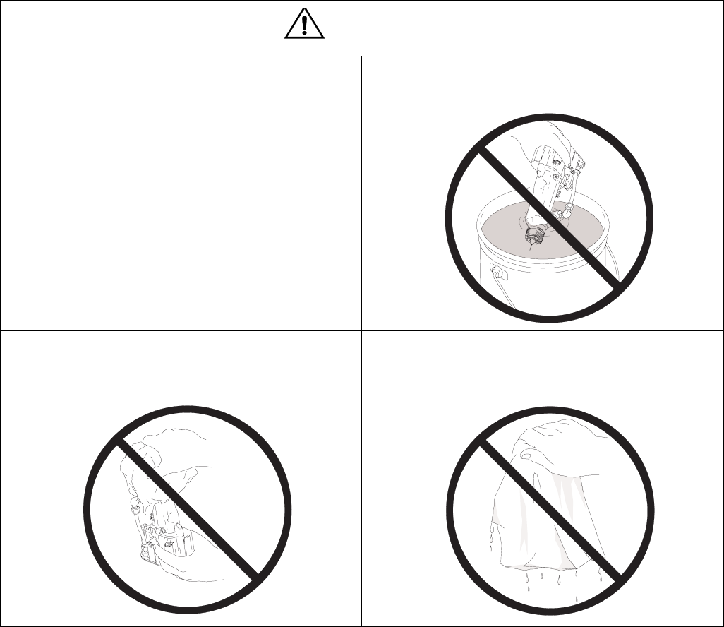
CAUTION
•Clean all parts with a non-conductive, compatible
solvent. Conductive solvents can cause the gun to
malfunction.
•Do not use methylene chloride as a flushing or
cleaning solvent with this gun as it will damage
nylon components.
•Fluid in the air passages could cause the gun to
malfunction and could draw current and reduce the
electrostatic effect. Fluid in the power supply cavity
can reduce the alternator life. Whenever possible,
point the gun down when cleaning it. Do not use
any cleaning method which could allow fluid into
the gun air passages.
Do not immerse the gun in fluid.
Do not point the gun up while cleaning it. Do not wipe the gun with a cloth that is heavily
saturated; wring out the excess fluid.
TI1573A
TI1574A
02027A
Maintenance
309297L 23
Daily Care and Cleaning,
continued
•Clean the fluid and air line filters daily.
•Clean the outside of the gun daily with a soft cloth
dampened in a compatible solvent.
•Clean the air cap and fluid nozzle daily, minimum.
Some applications require more frequent cleaning.
Replace the fluid nozzle and air cap if they are dam-
aged. See Clean the Air Cap and Fluid Nozzle,
page 24.
•Check the electrode and replace if broken or dam-
aged. See Electrode Replacement on page 35.
•Check for fluid leakage from the gun and fluid
hoses. See Check for Fluid Leakage on page 25.
Tighten fittings or replace equipment as needed.
•Flush the gun before changing colors and whenever
you are done operating the gun.
WARNING
Pressurized Equipment Hazard
To reduce the risk of an injury, follow the
Pressure Relief Procedure on page 17
before doing any maintenance on the gun
or system.
WARNING
Fire, Explosion, and Electric Shock Hazard
To reduce the risk of fire, explosion, or elec-
tric shock, turn off the turbine air (TA)
before flushing the gun or any part of the
system.

Maintenance
24 309297L
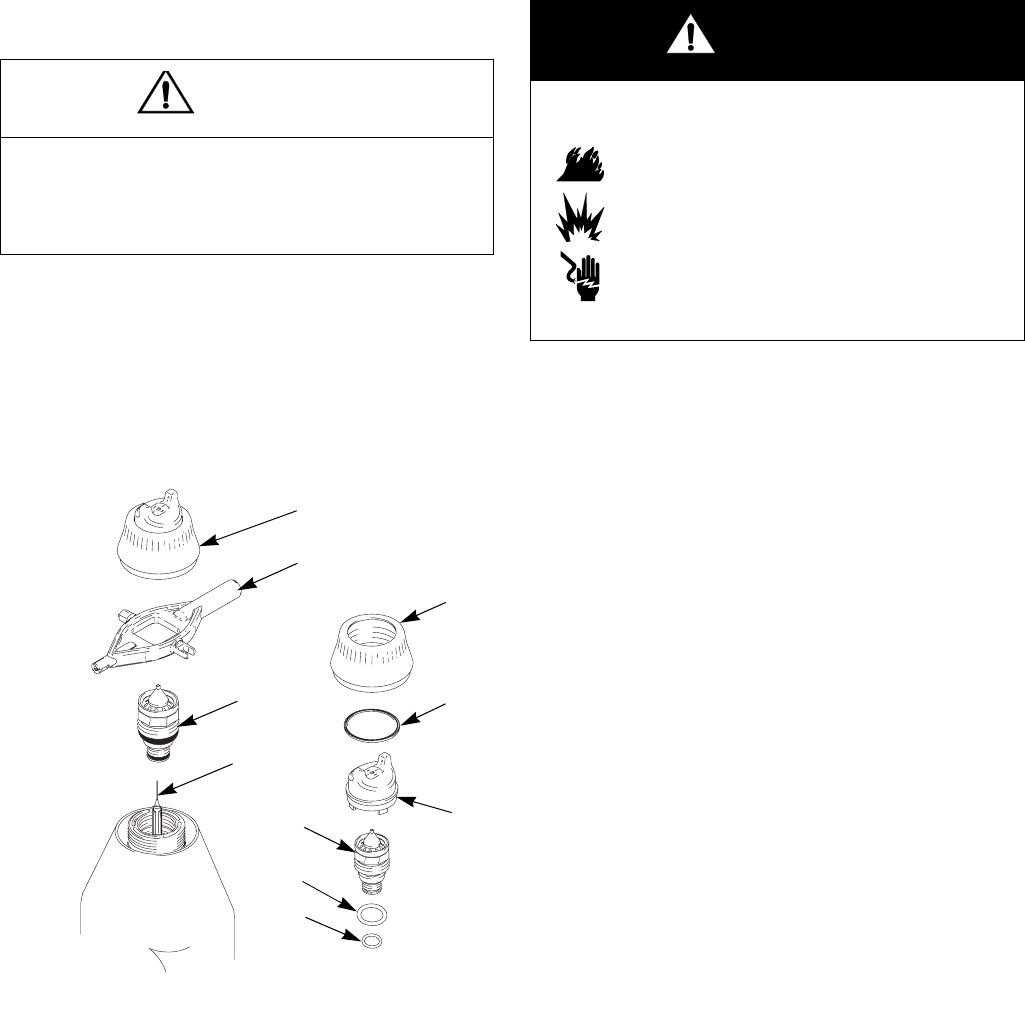
Clean the Air Cap and Fluid
Nozzle
Equipment Needed
•soft bristle brush
•compatible solvent
Procedure
1. Relieve the pressure.
2. Remove the air cap assembly (1, 3) and shroud (2).
See F
IGURE
13.
3. Wipe the fluid nozzle (4), shroud (2), and exterior of
the gun clean with a cloth dampened in solvent.
Avoid getting any solvent into the air passages.
Whenever possible, point the gun down when
cleaning it.
4. If it appears that there is paint inside the fluid nozzle
(4) air passages, remove the gun from the line for
servicing.
5. Clean the air cap (3) with the soft bristle brush and
solvent or submerge the air cap in suitable solvent
and wipe it clean.
6. Slide the shroud (2) onto the gun.
7. Carefully install the air cap (3). Be sure to insert the
electrode (7) through the center hole of the air cap.
Rotate the air cap to the desired position.
8. Make sure the u-cup (1a) is in place on the retaining
ring (1). The lips must face forward. Tighten the
retaining ring until the air cap is held firmly in place;
you should not be able to rotate the air cap horns by
hand.
9. Test gun resistance, page 26.
Fig. 13. Clean Air Cap and Fluid Nozzle
WARNING
Pressurized Equipment Hazard
To reduce the risk of an injury, follow the
Pressure Relief Procedure on page 17
when you stop spraying and whenever you
are instructed to relieve the pressure.
CAUTION
Do not use metal tools to clean the
air cap or fluid nozzle holes as this
could scratch them, and make sure
the electrode is not damaged.
Scratches in the air cap or nozzle or
a damaged electrode can distort the
spray pattern.
TI1560A
2
47
13
1a
Maintenance
309297L 25
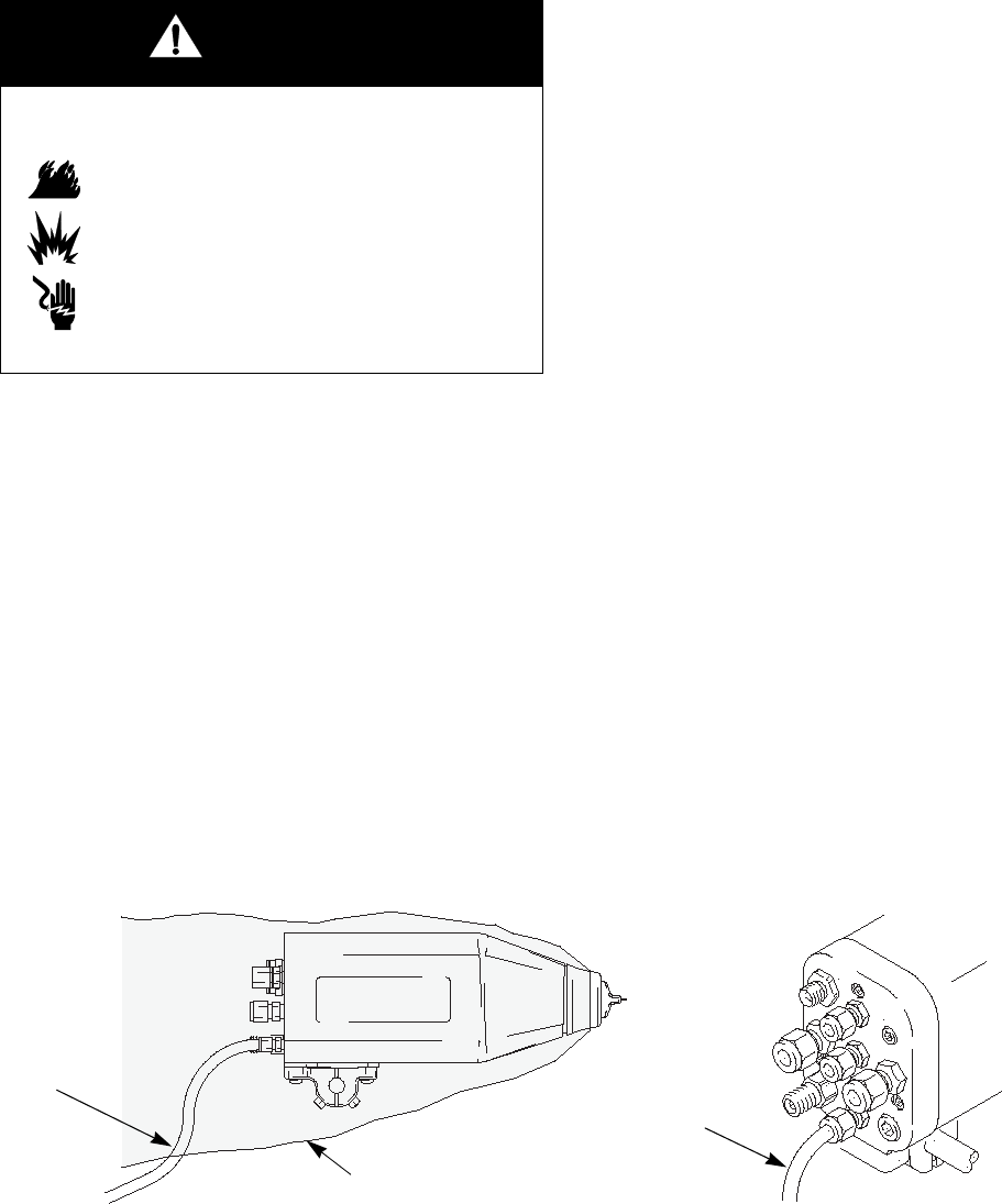
Check for Fluid Leakage
During operation, periodically check the manifold
exhaust tube (YY) and both ends of the gun shroud (ZZ)
for the presence of fluid. See F
IGURE
14. Fluid in these
areas indicates leakage into the shroud, which could be
caused by leaks at the fluid tube connections or fluid
packing leakage.
If fluid is seen in these areas, stop spraying immedi-
ately. Relieve the pressure, then remove the gun for
repair.
Fig. 14. Check for Fluid Leakage
WARNING
Fire and Explosion Hazard
If any fluid leakage from the gun is
detected, stop spraying immediately. Fluid
leakage into the gun shroud could cause
fire or explosion and result in serious injury
and property damage.
WARNING
Pressurized Equipment Hazard
To reduce the risk of an injury, follow the
Pressure Relief Procedure on page 17
when you stop spraying and whenever you
are instructed to relieve the pressure.
ti1571a
TI1579A
YY
YY
ZZ
ZZ
Electrical Tests
26 309297L
Electrical Tests
Electrical components inside the gun affect performance
and safety. The following procedures test the condition
of the power supply (12) and electrode (7), and electrical
continuity between components.
Use megohmmeter Part No. 241079 (AA) and an
applied voltage of 500 V. Connect the leads as shown.
Test Gun Resistance
1. Flush and dry the fluid passage.
2. Measure resistance between the electrode needle
tip (7) and the gun body (32) or the turbine air inlet
fitting (TA); it should be 156-180 megohms. If out-
side this range, remove the gun for service (page
32) and go to the next test. If in range, refer to Elec-
trical Troubleshooting on page 31 for other possi-
ble causes of poor performance.
Fig. 15. Test Gun Resistance
WARNING
Fire, Explosion, and Electric Shock Hazard
Megohmmeter Part No. 241079 (AA-see
F
IGURE
15) is not approved for use in a haz-
ardous area. To reduce the risk of sparking,
do not use the megohmmeter to check
electrical grounding unless:
•The gun has been removed from the haz-
ardous area;
•Or all spraying devices in the hazardous
area are turned off, ventilation fans in the
hazardous area are operating, and there
are no flammable vapors in the area
(such as open solvent containers or
fumes from spraying).
Failure to follow this warning could cause
fire, explosion, and electric shock and result
in serious injury and property damage.
TI1585B
TI1577A
AA
7
TA
TA
Electrical Tests
309297L 27
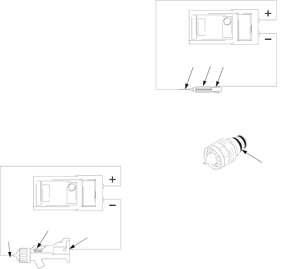
Test Power Supply
Resistance
1. Remove the power supply (12), page 42.
2. Remove the turbine alternator (13) from the power
supply, page 43.
3. Measure resistance from the power supply's ground
strips (EE) to the spring (12b). See F
IGURE
16.
4. The resistance should be 135-150 megohms. If out-
side this range, replace the power supply. If in
range, proceed to the next test.
5. If you still have problems, refer to Electrical Trou-
bleshooting on page 31 for other possible causes
of poor performance, or contact your Graco distribu-
tor.
6. Be sure the spring (12b) is in place before reinstall-
ing the power supply.
Fig. 16. Test Power Supply Resistance
ti1599a
EE
12b
Electrical Tests
28 309297L
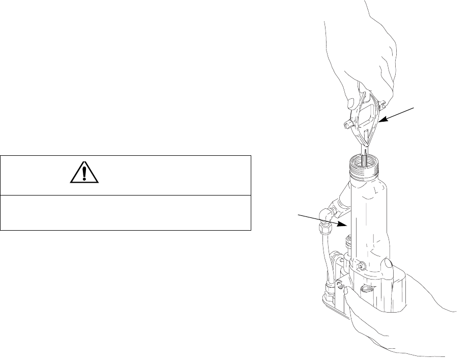
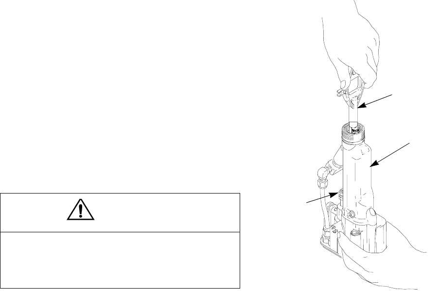
Test Electrode Resistance
1. Insert a conductive rod (B) into the gun barrel
(removed for the power supply test) and against the
metal contact (C) in the front of the barrel.
2. Measure the resistance between the conductive rod
(B) and the electrode (7). The resistance should be
20-30 megohms. See F
IGURE
17.
3. If in range, refer to Electrical Troubleshooting on
page 31 for other possible causes of poor perfor-
mance, or contact your Graco distributor.
4. Remove the electrode (7), page 35. Measure the
resistance between the contact (E) and the elec-
trode wire (F). The resistance should be 20-30 meg-
ohms. If out of range, replace the electrode. See
F
IGURE
18.
5. Make sure the metal contact (C) in the barrel, the
nozzle contact ring (4a, F
IGURE
19), and the elec-
trode contacts (E) are clean and undamaged.
Fig. 17. Test Electrode Resistance
Fig. 18. Electrode
Fig. 19. Nozzle Conductive O-Ring
ti1499a
B
7
C
ti1548a
F7E
ti1513a
4a

Troubleshooting
309297L 29
Troubleshooting
Check all possible remedies in the Troubleshooting
Chart before disassembling the gun.
Spray Pattern Troubleshooting
Some spray pattern problems are caused by the improper balance between air and fluid.
WARNING
Electric Shock Hazard
Installing and servicing this equipment
requires access to parts which may cause
an electric shock or other serious injury if
the work is not performed properly. Do not install or
repair this equipment unless you are trained and
qualified.
WARNING
Pressurized Equipment Hazard
To reduce the risk of an injury, follow the
Pressure Relief Procedure on page 17
whenever you are instructed to relieve the
pressure.
Problem Cause Solution
Fluttering or spitting spray. No fluid. Refill supply.
Loose, dirty, damaged nozzle/seat. Clean or replace nozzle, page 34.
Air in fluid supply. Check fluid source. Refill.
Improper spray pattern. Damaged nozzle or air cap. Replace, page 34.
Fluid buildup on air cap or nozzle. Clean. See page 24.
Fan air pressure too high. Decrease.
Fluid too thin. Increase viscosity.
Fluid pressure too low. Increase.
Fan air pressure too low. Increase.
Fluid too thick. Reduce viscosity.
Too much fluid. Decrease flow.
Streaks. Did not apply 50% overlap. Overlap strokes 50%.
Dirty or damaged air cap. Clean or replace, page 34.

Troubleshooting
30 309297L
Gun Operation Troubleshooting
Problem Cause Solution
Excessive spray fog. Atomizing air pressure too high. Decrease air pressure as low as pos-
sible.
Fluid too thin. Increase viscosity.
“Orange Peel” finish. Atomizing air pressure too low. Increase air pressure; use lowest air
pressure necessary.
Poorly mixed or filtered fluid. Remix or refilter fluid.
Fluid too thick. Reduce viscosity.
Fluid leaks from the fluid packing
area
Worn packings or rod. Replace packings or rod; see pages
36 or 37.
Air leaks from the air cap Worn piston stem o-rings (34e, 34f). Replace; see page 38.
Fluid leakage from the front of the
gun
Worn or damaged packing rod (8). Replace; see page 36
Worn fluid seat. Replace fluid nozzle (4) and/or elec-
trode needle (7); see pages 34 to 35.
Loose fluid nozzle (4). Tighten; see page 34.
Damaged nozzle o-ring (4b). Replace; see page 34.
Gun does not spray Low fluid supply. Add fluid if necessary.
Damaged air cap (3). Replace; see page 34.
Dirty or clogged fluid nozzle (4). Clean; see page 34.
Damaged fluid nozzle (4). Replace; see page 34.
Piston (34) not actuating. Check cylinder air. Check piston
u-cup (34d); see page 38.
Actuator arm (29) is out of position. Check actuator arm and nuts. See
page 39.
Dirty air cap Misaligned air cap (3) and fluid noz-
zle (4).
Clean fluid buildup off air cap and
fluid nozzle seat; see page 24.
Damaged nozzle orifice. Replace nozzle (4); see page 34.
Fluid is coming on before the air. Check actuator arm and nuts. See
page 39.
Air leaks from manifold Manifold is not tight. Tighten manifold screws (106).
Fluid leaks at the quick-disconnect. Manifold is not tight. Tighten manifold screws (106).
Fluid hose o-rings are worn or miss-
ing.
Inspect or replace o-rings.

Troubleshooting
309297L 31
Electrical Troubleshooting
Problem Cause Solution
Poor wrap. Turbine air is not turned on. Turn on.
Booth exhaust velocity is too high. Reduce velocity to within code limits.
Atomizing air pressure too high. Decrease.
Fluid pressure too high. Decrease.
Incorrect distance from gun to part. Should be 8-12 in. (200-300 mm).
Poorly grounded parts. Resistance must be 1 megohm or
less. Clean workpiece hangers.
Faulty gun resistance. See Test Gun Resistance on page
26.
Low fluid resistivity. Check fluid resistivity, page 15.
Fluid leaks from the packing (8d) and
causes a short.
Clean the packing rod cavity.
Replace the packing rod. See page
37.
Faulty turbine alternator. Be sure the plug is in place on the
back of the turbine alternator hous-
ing. Remove and test the turbine
alternator. See page 43.
The KV switch is stuck on low. Check the switch actuation; replace if
needed.
No power. Replace power supply. See page 42.
No voltage or low voltage reading on
the gun ES display module
Damaged fiber optic cable or connec-
tion.
Check; replace damaged parts.
Turbine air is not turned on. Turn on.
Poor wrap. See causes and solutions under Poor
Wrap, above.
Operator gets mild shock. Operator not grounded or is near
ungrounded object.
See Grounding on page 13.
Gun not grounded. See Check Electrical Grounding on
page 14 and Test Gun Resistance
on page 26.
Operator gets shock from workpiece. Workpiece not grounded. Resistance must be 1 megohm or
less. Clean workpiece hangers.
Repair
32 309297L
Repair
Prepare the Gun for Service
•Check all possible remedies in Troubleshooting
before disassembling the gun.
•Use a vise with padded jaws to prevent damage to
plastic parts.
•Lubricate the power supply o-ring (12a), some pack-
ing rod parts (8), and certain fluid fittings with Part
No. 116553 Dielectric Grease, as specified in the
text.
•Lightly lubricate o-rings and seals with non-silicone
grease. Order Part No. 111265 Lubricant. Do not
over-lubricate.
•Only use genuine Graco parts. Do not mix or use
parts from other PRO Gun models.
1. Flush and clean the gun, page 22.
2. Relieve the pressure, page 17.
3. Remove the gun from the manifold, page 33.
4. Remove the gun from the worksite. Repair area
must be clean.
WARNING
Electric Shock Hazard
Installing and repairing this equipment
requires access to parts that may cause
electric shock or other serious injury if the
work is not performed properly. Do not install or ser-
vice this equipment unless you are trained and quali-
fied.
WARNING
Pressurized Equipment Hazard
To reduce the risk of injury, follow the Pres-
sure Relief Procedure on page 17 before
checking or servicing any part of the system
and whenever you are instructed to relieve the pres-
sure.
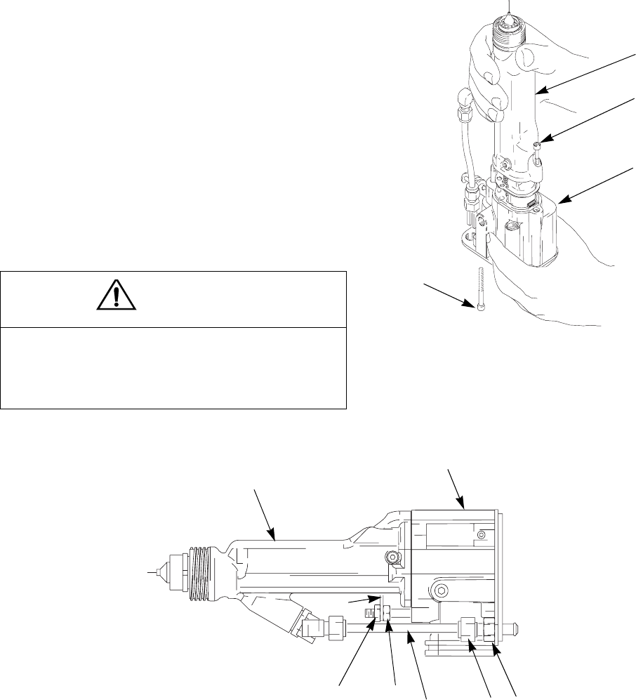
Repair
309297L 33
Remove the Gun from the
Manifold
1. Loosen the bottom gun screw (31) until the gun sits
loosely in the mounting bracket slot (A). See F
IGURE
20.
2. Holding the gun firmly in hand, loosen the three
screws (106) from the back of the manifold.
3. Remove the gun from the manifold and take it to the
service area.
Fig. 20. Remove Gun from Manifold
Install the Gun on the
Manifold
1. Make sure the gasket (112) and spring (105) are in
place on the manifold. See F
IGURE
20. Inspect the
parts for damage and replace them as needed.
2. Secure the gun to the manifold by tightening the
three screws (106).
3. Secure the gun to the mounting bracket (102) by
tightening the bottom screw (31).
CAUTION
The piston return spring (105) is compressed
between the manifold and the gun body when they
are assembled. To avoid sudden movement of the
gun, loosen the bottom gun screw (31) before loos-
ening the three manifold screws (106). This allows
the gun to move forward gradually as the manifold
screws are loosened. Hold the gun firmly in hand
while loosening the manifold screws.
TI1559A
106
105
112
102
A
Repair
34 309297L
Air Cap/Nozzle Replacement
1. Prepare gun for service, page 32.
2. Remove the retaining ring (1) and air cap (3). See
F
IGURE
21.
3. Point gun up while removing the fluid nozzle (4)
assembly with the multi-tool (40).
Fig. 21. Air Cap/Nozzle Replacement
Use non-silicone grease, Part No. 111265, on the small
o-ring (4b). Do not over-lubricate. Do not lubricate the
contact ring (4a).
4. Lightly lubricate the o-ring (4b). Install it and the
contact ring (4a) on the nozzle (4).
Make sure the electrode needle (7) is finger- tight (page
35).
5. Install the fluid nozzle (4) with the multi-tool (40).
Tighten until the fluid nozzle seats in the gun barrel
(1/8 to 1/4 turn past hand-tight).
6. Carefully install the air cap (3). Be sure to insert the
electrode (7) through the center hole of the air cap.
Rotate the air cap to the desired position.
7. Make sure the u-cup (1a) is in place on the retaining
ring (1). The lips must face forward. Tighten the
retaining ring until the air cap is held firmly in place;
you should not be able to rotate the air cap horns by
hand.
8. Test gun resistance, page 26.
9. Install the gun onto the manifold and bracket. See
page 33.
CAUTION
Hold the front end of the gun up and trigger the gun
while removing the nozzle to help drain the gun and
prevent any paint or solvent left in the gun from enter-
ing the air passages.
TI1572A
1, 3
3
4
4a
4b
1
40
4
7
1a
WARNING
Fire, Explosion, and Electric Shock Hazard
The nozzle contact ring (4a) is a conductive
contact ring, not a sealing o-ring. To reduce
the risk of sparking or electric shock, do not
remove the nozzle contact ring (4a) except
to replace it and never operate the gun
without the contact ring in place. Do not
replace the contact ring with anything but a
genuine Graco part.
Repair
309297L 35
Electrode Replacement
1. Prepare the gun for service, page 32.
2. Remove the air cap and nozzle, page 34. Remove
the gun shroud (2).
3. Unscrew the electrode (7) with the multi-tool (40).
Hold the packing rod end (8h) to prevent it from
turning, F
IGURE
22.
4. Apply low-strength (purple) Loctite
®
or equivalent
thread sealant to the electrode and packing rod
threads. Install the electrode finger-tight. Do not
overtighten.
5. Install the fluid nozzle, page 34.
6. Test gun resistance, page 26.
7. Install the gun shroud (2) and air cap, page 34.
8. Install the gun onto the manifold and bracket. See
page 33.
Fig. 22. Electrode Replacement
CAUTION
To avoid damaging the plastic threads, be very care-
ful when installing the electrode.
TI1565A
40
8h
Repair
36 309297L
Fluid Packing Removal
You may replace the packing rod as an assembly, as
described below, or as individual parts (see page 37).
The assembly is pre-adjusted at the factory.
1. Prepare the gun for service, page 32.
2. Remove the air cap, page 34. Remove the gun
shroud (2).
3. Remove the jam nut (28) and actuator arm (29).
See page 38.
The fluid nozzle (4) must be in place when removing or
installing the jam nut and actuator arm.
4. Remove the fluid nozzle (4) and electrode (7). See
pages 34 and 35.
5. Remove the packing rod (8), using the multi-tool
(40).
6. Check all parts for wear or damage and replace if
necessary.
Before installing the packing rod, clean the internal sur-
face of the barrel (9) with a soft cloth or brush. Check for
marks from high voltage arcing. If marks are present,
replace the barrel.
Fig. 23. Fluid Packing Removal
CAUTION
Clean all parts in non-conductive solvent compatible
with the fluid being used, such as xylol or mineral
spirits. Use of conductive solvents can cause the gun
to malfunction.
TI1566A
40
28
9
Repair
309297L 37
Packing Rod Repair
You may replace the packing rod as individual parts, as
described below, or as an assembly (see page 36). The
assembly is pre-adjusted at the factory.
Before installing the fluid packing rod into the gun barrel,
make sure the internal surfaces of the barrel are clean.
Remove any residue with a soft brush or cloth. Check
the inside of the barrel for marks from high voltage arc-
ing. If marks are present, replace the barrel.
To
assemble the individual parts:
1. Place the packing nut (8e) and seal (8b) on the fluid
rod (8h). Flats on the packing nut must face the
back of the fluid rod. The seal o-ring must face away
from the packing nut. See F
IGURE
24.
2. Fill the inner cavity of the spacer (8g) with dielectric
grease. Place the spacer on the fluid rod (8h) in the
direction shown. Generously apply dielectric grease
to the outside of the spacer.
3. Place the rod packing (8d), packing spreader (8c),
and housing (8f) on the packing rod (8h).
4. Lightly tighten the packing nut (8e). The packing nut
is properly tightened when there is 3 lb (13.3 N) of
drag force when sliding the packing housing (8f)
assembly along the rod. Tighten or loosen the pack-
ing nut as needed.
5. Install the o-ring (8a) on the outside of housing (8f).
Lubricate the o-ring with non-silicone grease, Part
No. 111265. Do not over-lubricate.
6. Install the spring (25) against the nut (E) as shown.
7. Install the packing rod assembly (8) into the gun
barrel. Using the multi-tool (40), tighten the assem-
bly until just snug.
8. Install the electrode, page 35 and nozzle, page 34.
9. Install and adjust the actuator arm (29) and jam nut
(28). See page 39.
10. Test gun resistance, page 26.
11. Install the gun shroud (2) and air cap, page 34.
12. Install the gun onto the manifold and bracket. See
page 33.
Fig. 24. Packing Rod
TI1489A
8a
8b
8c
8d
8e
8f
8g
8h
E
25
Repair
38 309297L
Piston Repair
1. Prepare the gun for service, page 32.
2. Remove the air cap, page 34. Remove the gun
shroud (2).
3. Remove the jam nut (28), actuator arm (29), and
adjustment nut (30). See F
IGURE
25.
The fluid nozzle (4) must be in place when removing or
installing the jam nut and actuator arm.
Fig. 25. Actuator Arm
4. Push on the piston rod (34b) to push the piston out
the back of the gun.
5. Inspect the o-rings (34e, 34f, 34g) and u-cup pack-
ing (34d) for damage. See Table 5 and F
IGURE
26.
6. Lubricate the o-rings (34e, 34f, 34g) and u-cup
packing (34d) with non-silicone grease, Part No.
111265. Do not over-lubricate.
7. Align the two stems (34c) with the holes in the gun
body and press the piston assembly into the back of
the gun until it bottoms.
8. Install and adjust the actuator arm, page 39.
Fig. 26. Piston O-Rings
TI1709A
28 29 30 34b
Table 5: Piston O-Rings
Description Function
Shaft O-Ring
(34g)
Seals cylinder air along the piston rod
(34b). Replace if air leaks along rod.
Front O-Ring
(34e)
Air shutoff seal. Replace if air leaks from
air cap when gun is de-triggered.
Back O-Ring
(34f)
Separates cylinder air from fan and
atomizing air.
U-Cup (34d) Replace if air leaks from small vent hole
at back of manifold when gun is trig-
gered.
TI1575A
TI1576A
34a
34d
34c
34f
34e
34g
34b
34e
34g
34f
34d
Atomizing Air Side
Fan Air Side
Repair
309297L 39
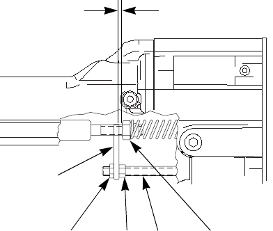
Adjust the Actuator Arm
The fluid nozzle (4) must be in place when removing or
installing the jam nut and actuator arm.
1. Install the adjustment nut (30), actuator arm (29),
and jam nut (28) onto the piston rod (34b). Note that
the jam nut (28) has a slightly larger hex and a thin-
ner profile than the adjustment nut (30). See F
IGURE
25 on page 38.
2. Position the parts so there is a 0.125 in. (3 mm) gap
between the actuator arm (29) and the fluid packing
rod nut (E), which allows the atomizing air to actuate
before the fluid. See F
IGURE
27.
3. Tighten the adjustment nut (30) against the actuator
arm (29). Check that the 0.125 in. (3 mm) gap has
been maintained. In addition, there should be 3-4
mm of electrode needle travel when the gun is trig-
gered. Adjust the jam nut position to obtain these
dimensions.
4. Test gun resistance, page 26.
5. Install the gun shroud (2) and air cap (3), page 34.
6. Install the gun onto the manifold and bracket. See
page 33.
Fig. 27. Actuator Arm Adjustment
TI1567A
28
29
30 34b E
0.125 in. (3 mm) gap
Repair
40 309297L
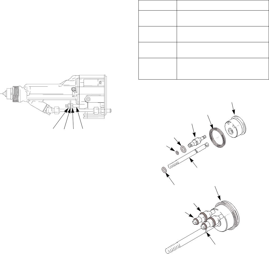
Barrel Removal
1. Prepare the gun for service, page 32.
2. Remove the air cap, page 34. Remove the gun
shroud (2).
3. Carefully loosen the fluid fitting nut (20). Pull the
tube (19) out of the fitting (23). Make sure both fer-
rules (21, 22) and the nut stay with the tube.
4. Remove the jam nut (28) and actuator arm (29).
See page 38.
5. Loosen the three screws (10, 33). See F
IGURE
28.
6. Hold the gun body (32) with one hand and pull the
barrel (9) straight off the body. See F
IGURE
28.
Fig. 28. Barrel Removal
Fig. 29. Disconnect Fluid Tube
CAUTION
To avoid damaging the power supply (12), pull the
gun barrel (9) straight away from the gun body (32). If
necessary, gently move the gun barrel from side to
side to free it from the gun body.
TI1563A
10
32
9
33
TI1709A
28
29
30
19
32
9
20 23

Repair
309297L 41
Barrel Installation
1. Be sure the gasket (11) and grounding spring (51)
are in place. Make sure the air holes are aligned
properly. Replace if damaged. See F
IGURE
30.
2. Place the barrel (9) over the power supply (12) and
onto the gun body (32).
3. Tighten the three screws (10, 33) oppositely and
evenly (about a half turn past snug).
4. Assemble the fluid tube (19) into the fluid fitting (23).
Ensure that the ferrules (21, 22) are in place.
Tighten the nut (20).
5. Install and adjust the actuator arm (29) and jam nut
(28). See page 39.
6. Test gun resistance, page 26.
7. Install the gun shroud (2) and air cap, page 34.
8. Install the gun onto the manifold and bracket. See
page 33.
Fig. 30. Barrel Installation
CAUTION
Do not over-tighten the screws (10, 33).
TI1569A
9
11
10
12
32
51 28
29
19
20
23
33

Repair
42 309297L
Power Supply Removal and
Replacement
•Inspect the gun body power supply cavity for dirt or
moisture. Clean with a clean, dry rag.
•Do not expose gasket (11) to solvents.
1. Prepare gun for service, page 32.
2. Remove the barrel (9), page 40.
3. Grasp the power supply (12) with your hand. With a
gentle side to side motion, free the power sup-
ply/alternator assembly from the gun body (32),
then carefully pull it straight out. Disconnect the flex-
ible circuit (39) from the socket at the top of the
body (32). See F
IGURE
31.
4. Disconnect the 3-wire connector (GG) from the
power supply. Slide the alternator up and off the
power supply. Inspect the power supply and alterna-
tor for damage. Disconnect the 6-pin flexible circuit
(39) from the power supply.
5. Check the power supply resistance, page 27.
Replace if necessary.
Before installing the power supply, make sure the
o-rings (12a, 13a), spring (12b), and pads (13e) are in
place.
6. Connect the 6-pin flexible circuit (39) to the power
supply.
7. Connect the 3-wire connector (GG). Slide the alter-
nator (13) down onto the power supply (12).
8. Lubricate the alternator o-ring (13a) with non-sili-
cone grease, Part No. 111265. Do not over-lubri-
cate.
9. Lubricate the power supply o-ring (12a) with dielec-
tric grease.
10. Insert the power supply/alternator assembly in the
gun body (32). Make sure the ground strips make
contact with the body. Connect the flexible circuit
(39) to the socket at the top of the body. Push the
6-pin connector into the socket to ensure it is prop-
erly connected.
11. Install the barrel (9), page 41.
12. Test gun resistance, page 26.
CAUTION
Be careful when handling the power supply (12) to
avoid damaging it.
Repair
309297L 43
Fig. 31. Power Supply
Turbine Alternator Removal
and Replacement
Replace turbine alternator bearings after 2000 hours of
operation. Order Part No. 223688 Bearing Kit.
1. Prepare gun for service, page 32.
2. Remove the power supply/alternator assembly,
page 42.
3. Disconnect the alternator from the power supply,
page 42.
4. Measure resistance between the two outer termi-
nals of the 3-wire connector (GG); it should be
2.5-3.5 ohms. If outside this range, replace the alter-
nator coil.
5. Follow the bearing replacement procedure in the
bearing kit manual 308034.
6. Install the alternator on the power supply, page 42.
7. Install the power supply/alternator assembly, page
42.
TI1568A
13
12a
12b
11
13a
GG
12
13e
32
39

Repair
44 309297L
Notes
Parts
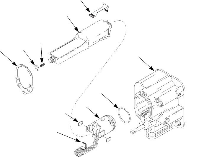
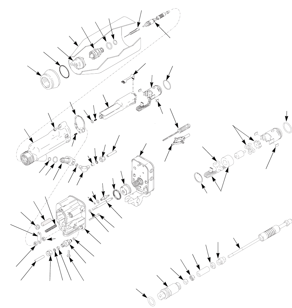
309297L 45
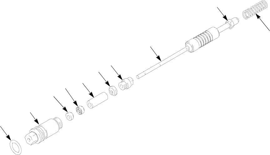
Parts
Part No. 244589 PRO Auto Xs Electrostatic Gun, Series B, for standard coatings
ti1601a
TI1481a
TI1558A
7
18
16
12
19
15
34a
35
9
4a 4b
10
12a
12b
32
2
34d
1
3
4
8
11
13
13e
13a
20
22
21
17
14 34c
34f
34e
34g
34b
30
27
26
29
28
24
31
23
25
19 (Ref) 20 21
22
13a
13b
13b
13c
Ref. No. 13: Alternator Detail
13d
13e
8a
8b
8c
8d
8e
8f
8g
8h
Ref. No. 8: Packing Rod Detail
39
1a
40
41
33
51
Parts
46 309297L
Part No. 244589 PRO Auto Xs Electrostatic Gun, Series B, for standard coatings
Ref.
No. Part No. Description Qty
1 244950 RING, retaining, air cap; includes
1a
1
1a*† 198307 . U-CUP 1
2 245312 SHROUD 1
3 24A438 AIR CAP 1
4 197266 NOZZLE; 1.5 mm orifice; includes
4a and 4b
1
4a 111261 . O-RING, conductive 1
4b 111507 . O-RING; fluoroelastomer 1
5 198486 CONNECTOR, tube, fiber optic;
pictured on page 51 (unassem-
bled)
1
7 276697 NEEDLE, electrode 1
8 244521 ROD, packing; includes 8a-8h 1
8a* 111316 . O-RING; fluoroelastomer 1
8b* 116905 . SEAL 1
8c* 178409 . SPREADER, packing; uhmwpe 1
8d* 178763 . PACKING, rod; acetal 1
8e 197641 . NUT, packing 1
8f 185495 . HOUSING, packing 1
8g* 186069 . SPACER, packing; acetal 1
8h 244696 . ROD, packing 1
9 244394 BARREL, gun 1
10 197518 SCREW; socket-hd; 10-24 x 3/4
in. (19 mm)
1
11*† 197517 GASKET, barrel 1
12 244541 POWER SUPPLY, 85 kV; includes
12a-12b
1
12a*† 103337 . O-RING; fluoroelastomer 1
12b 197624 . SPRING, compression 1
13 244555 TURBINE, alternator; includes
13a-13e
1
13a*† 110073 . O-RING; fluoroelastomer 1
13b 223688 . BEARING KIT; includes front
and rear bearings and fan
1
13c 244577 . COIL 1
13d 111745 . RING, retaining 1
13e 198821 . PAD, pressure 2
14* 111316 O-RING 1
15* 102982 O-RING 1
16 189757 FITTING, fluid 1
17 112642 SPACER 1
18 111370 CONNECTOR, elbow; includes
items 20, 21, 22
1
19 198043 TUBE, fluid 1
20 112644 NUT 1
21* 111285 FERRULE, back 1
22* 111286 FERRULE, front 1
23 189549 FITTING, fluid, quick-disconnect 1
24* 111450 O-RING 1
25 185111 SPRING, compression 1
26 189367 CAP, exhaust 1
27 185122 MUFFLER 1
28 101324 NUT, jam, hex 1
29 197919 ARM, actuator 1
30 102025 NUT, hex 1
31 112689 SCREW, button-hd; 1/4-20 x 3/4
in. (19 mm)
1
32 245662 BODY, gun 1
Ref.
No. Part No. Description Qty
Parts
309297L 47
* Recommended spare parts. Keep on hand to reduce
downtime.
† Included in repair kit 15D592.
Replacement Warning labels, signs, tags, and cards are
available at no cost.
33 116575 SCREW, cap, socket-hd; 10-24; 3
in. (76 mm)
2
34 244702 PISTON; includes 34a-34g 1
34a 197920 . PISTON 1
34b 189754 . ROD, piston 1
34c 189355 . STEM, piston 2
34d*† 189752 . PACKING, u-cup 1
34e*† 111504 . O-RING 2
34f*† 112319 . O-RING 2
34g*† 111508 . O-RING 1
35 244586 MANIFOLD; see separate parts
list on page 51
1
39 245265 CIRCUIT, flexible 1
40 276741 MULTI-TOOL 1
Ref.
No. Part No. Description Qty
41 107460 WRENCH, ball end; 4 mm 1
42 179791 TAG, warning (not shown);
replacement available at no cost
1
43 180060 SIGN, warning (not shown);
replacement available at no cost
1
44 239945 COVER, gun; box of 10 (not
shown)
1
51 197624 SPRING, grounding 1
Ref.
No. Part No. Description Qty
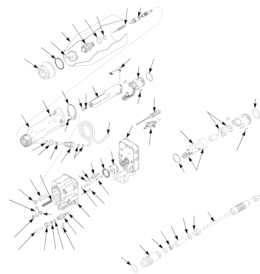
Parts
48 309297L
Part No. 244590 PRO Auto Xs Electrostatic Gun, Series B, for high conductivity coatings
ti1601a
TI1586A
7
19 (Ref)
12
19
34a
35
9
4a 4b
10
12a 12b
32
2
34d
1
3
4
8
11
13
13e
13a
19c
19d
19b
34c
34f
34e
34g
34b
30
27
26
29
28
24
31
23
25
19 (Ref) 20 21
22
8a
8b
8c
8d
8e
8f
8g
8h
Ref. No. 8: Packing Rod Detail
19a
39
1a
40
41
33
TI1481a
13a
13b
13b
13c
Ref. No. 13: Alternator Detail
13d
13e
51
Parts
309297L 49
Part No. 244590 PRO Auto Xs Electrostatic Gun, Series B, for high conductivity coatings
Ref.
No. Part No. Description Qty
1 244950 RING, retaining, air cap; includes
1a
1
1a*† 198307 . U-CUP 1
2 245312 SHROUD 1
3 24A438 AIR CAP 1
4 197266 NOZZLE; 1.5 mm orifice; includes
4a and 4b
1
4a 111261 . O-RING, conductive 1
4b 111507 . O-RING; fluoroelastomer 1
5 198486 CONNECTOR, tube, fiber optic;
pictured on page 51 (unassem-
bled)
1
7 276697 NEEDLE, electrode 1
8 244521 ROD, packing; includes 8a-8h 1
8a* 111316 . O-RING; fluoroelastomer 1
8b* 116905 . SEAL 1
8c* 178763 . SPREADER, packing; uhmwpe 1
8d* 178409 . PACKING, rod; acetal 1
8e 197641 . NUT, packing 1
8f 185495 . HOUSING, packing 1
8g* 186069 . SPACER, packing; acetal 1
8h 244696 . ROD, packing 1
9 244394 BARREL, gun 1
10 197518 SCREW; socket-hd; 10-24 x 3/4
in. (19 mm)
1
11*† 197517 GASKET, barrel 1
12 244541 POWER SUPPLY, 85 kV; includes
12a-12b
1
12a*† 103337 . O-RING; fluoroelastomer 1
12b 197624 . SPRING, compression 1
13 244555 TURBINE, alternator; includes
13a-13e
1
13a*† 110073 . O-RING; fluoroelastomer 1
13b 223688 . BEARING KIT; includes front
and rear bearings and fan
1
13c 244577 . COIL 1
13d 111745 . RING, retaining 1
13e 198821 . PAD, pressure 2
19 237297 TUBE, fluid; coiled; includes
19a-19d
1
19a* 102982 . O-RING 1
19b* 111450 . O-RING 1
19c* 103337 . O-RING 2
19d 186818 . FITTING 1
20 112644 NUT 1
21* 111285 FERRULE, back 1
22* 111286 FERRULE, front 1
23 189549 FITTING, fluid, quick-disconnect 1
24* 111450 O-RING 1
25 185111 SPRING, compression 1
26 189367 CAP, exhaust 1
27 185122 MUFFLER 1
28 101324 NUT, jam, hex 1
29 197919 ARM, actuator 1
30 102025 NUT, hex 1
31 112689 SCREW, button-hd; 1/4-20 x 3/4
in. (19 mm)
1
32 245662 BODY, gun 1
33 116575 SCREW, cap, socket-hd; 10-24; 3
in. (76 mm)
2
Continued on page 50.
Ref.
No. Part No. Description Qty
Parts
50 309297L
* Recommended spare parts. Keep on hand to reduce
downtime.
† Included in repair kit 15D592.
Replacement Warning labels, signs, tags, and cards are
available at no cost.
34 244702 PISTON; includes 34a-34g 1
34a 197920 . PISTON 1
34b 189754 . ROD, piston 1
34c 189355 . STEM, piston 2
34d*† 189752 . PACKING, u-cup 1
34e*† 111504 . O-RING 2
34f*† 112319 . O-RING 2
34g*† 111508 . O-RING 1
35 244586 MANIFOLD; see separate parts
list on page 51
1
39 245265 CIRCUIT, flexible 1
40 276741 MULTI-TOOL 1
Ref.
No. Part No. Description Qty
41 107460 WRENCH, ball end; 4 mm 1
42 179791 TAG, warning (not shown);
replacement available at no cost
1
43 180060 SIGN, warning (not shown);
replacement available at no cost
1
44 239945 COVER, gun; box of 10 (not
shown)
1
51 197624 SPRING, grounding 1
Ref.
No. Part No. Description Qty
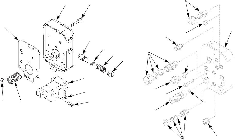
Parts
309297L 51
Part No. 244586 Manifold, Series A
† Included in repair kit 15D592.
TI1582A
TI1578A
101
101 (Ref)
102
103
104
105
106 (Ref)
107
106
111
110
118
119 114
112
117
109
113
116
116a
120
108
115
5 (see pages 46 or 49)
Ref.
No. Part No. Description Qty
101 198216 MANIFOLD 1
102 189581 BRACKET, reciprocator 1
103 110465 SCREW, set 2
104 112689 SCREW, button-hd 2
105 112640 SPRING, compression 1
106 197518 SCREW; socket-hd; 10-24 x 3/4
in. (19 mm)
3
107 111157 FITTING, tube, exhaust 1
108 186845 FITTING, turbine, air 1
109 110078 FITTING, tube, air 2
110 112646 PLUG 1
111 189551 FITTING, quick-disconnect, fluid 1
112† 197925 GASKET, manifold 1
113 108290 SCREW, machine 2
114 189365 CAP, kV, HI/LO 2
115 198764 RESTRICTOR 1
116 244772 PISTON; includes 116a 2
116a† 112085 . O-RING (1 per piston) 2
117 114263 FITTING, tube, air 3
118 111450 O-RING 1
119 116621 SPRING, compression 2
120 112645 PLUG 1
Ref.
No. Part No. Description Qty
Accessories
52 309297L
Accessories
Air Line Accessories
AirFlex
™
Flexible Grounded Air Hose
100 psi (7 bar, 0.7 MPa) Maximum Working Pressure
0.315 in. (8 mm) ID; 1/4 npsm(f) x 1/4 npsm(f) left-hand
thread
244963 6 ft (1.8 m)
244964 15 ft (4.6 m)
244965 25 ft (7.6 m)
244966 36 ft (11 m)
244967 50 ft (15 m)
244968 75 ft (23 m)
244969 100 ft (30.5 m)
Standard Grounded Air Hose (Grey)
100 psi (7 bar, 0.7 MPa) Maximum Working Pressure
0.315 in. (8 mm) ID; 1/4 npsm(f) x 1/4 npsm(f) left-hand
thread
223068 6 ft (1.8 m)
223069 15 ft (4.6 m)
223070 25 ft (7.6 m)
223071 36 ft (11 m)
223072 50 ft (15 m)
223073 75 ft (23 m)
223074 100 ft (30.5 m)
Bleed-Type Master Air Valve
300 psi (21 bar, 2.1 MPa) Maximum Working Pressure
Relieves air trapped in the air line between this valve
and the pump air motor when closed.
107141 3/4 npt
Air Line Shutoff Valve
150 psi (10 bar, 1.0 MPa) Maximum Working Pressure
For turning air to gun on or off.
224754 1/4 npsm(m) x 1/4 npsm(f) left-hand thread.
Fluid Line Accessories
Fluid Hose
225 psi (14 bar, 1.4 MPa) Maximum Working Pressure
FM Approved; nylon; 3/8 npsm(fbe)
215637 1/4 in. (6 mm) ID x 25 ft (7.6 m)
215638 1/4 in. (6 mm) ID x 50 ft (15.2 m)
Fluid Shutoff/Drain Valve
500 psi (35 bar, 3.5 MPa) Maximum Working Pressure
For turning fluid on or off to the gun and for relieving
fluid line pressure at the pump.
208630 1/2 npt(m) x 3/8 npt(f); carbon steel and
PTFE; for non-corrosive fluids
Drain Valve
300 psi (21 bar, 2.1 MPa) Maximum Working Pressure
236853 Mounts directly to gun manifold for faster
flushing and color changes. Must be used
with 233676 Fluid Recirculation Kit.
Fluid Recirculation Kit
233676 Converts standard gun to a recirculating
gun. Requires 236853 Drain Valve.
Gun Mounted Fluid Regulator
100 psi (7 bar, 0.7 MPa) Maximum Working Pressure
236854 Air-piloted fluid regulator mounts directly to
gun manifold for precise fluid control.
Accessories
309297L 53
Miscellaneous Accessories
Ground Wire and Clamp
222011 For grounding pump and other components
and equipment in the spray area.
12 gauge, 25 ft (7.6 m).
Megohmmeter
241079 500 Volt output; 0.01-2000 megohms.
Not for use in hazardous areas.
Paint Resistance Meter
722886 Use with 722860 Paint Probe to measure
resistance of paint.
Not for use in hazardous areas.
Paint Probe
722860 Use with 722886 Paint Resistance Meter to
measure resistance of paint.
Not for use in hazardous areas.
Safety Warning Signs
180060 English Warning Sign. FM Approved. Avail-
able at no charge from Graco.
ES Display Module
224117 Receives fiber optic transmission from the
PRO Auto Xs gun and displays the gun’s
output voltage and current. Mounts in a
standard 19 in. DIN rack. See 308265.
Fiber Optic Y Cables
See item T in F
IGURE
3 on page 9. For use with 224117
Display Module only. Connect gun manifold and display
module, or bulkhead connector and display module. See
308265.
224682 25 ft (7.6 m)
224684 50 ft (15 m)
224686 100 ft (30.5 m)
Fiber Optic Cables
See item V in F
IGURE
3 on page 9. Connect gun mani-
fold and remote voltage display, bulkhead connector
and remote display, or bulkhead connector and gun
manifold. See 308265.
224672 25 ft (7.6 m)
224674 50 ft (15 m)
224676 100 ft (30.5 m)
Power Supply
235301 Supplies low voltage DC power to 224117
Display Module. See 308265.
Remote Voltage Display
189762 Battery-operated meter displays actual
spraying voltage. remote mount outside
hazardous area. Connects to gun via fiber
optic cable. See 308265.
Remote Voltage Display Kits
Include 189762 Remote Voltage Display and fiber optic
cable.
236917 25 ft (7.6 m)
236919 50 ft (15 m)
236921 100 ft (30.5 m)
Bulkhead Connector
189870 For connecting two fiber optic cables.
Accessories
54 309297L
Gun Accessories
Round Pattern Kits
Consists of fluid tip, diffuser and air cap.
245217 4-6 in. (102-152 mm) diameter
245219 8-10 in. (203-254 mm) diameter
Dielectric Grease
116553 1 oz (28 g) tube of dielectric grease for the
power supply o-ring (12a), some packing
rod parts (8), and certain fluid fittings.
Gun Valve Lubricant
111265 4 oz (113 g) tube of sanitary (non-silicone)
lubricant for fluid seals and wear areas.
Alternator Bearing Kit
223688 To repair the turbine alternator.
Cleaning Brush
105749 For cleaning air cap and fluid nozzle.
HC Conversion Kit
245324 Converts PRO Auto Xs standard coating
gun (Part No. 244589) to high conductivity
gun (244590). The kit is for use with fluids
with low resistivity values. See page 16.
Technical Data
309297L 55
Technical Data
Loctite® is a registered trademark of the Loctite Corporation.
Category Data
Maximum Working Fluid Pressure 100 psi (0.7 MPa, 7 bar)
Maximum Working Air Pressure 100 psi (0.7 MPa, 7 bar)
Minimum Air Pressure at Gun Inlet 40 psi (0.28 MPa, 2.8 bar)
Maximum Fluid Operating Temperature 120°F (48°C)
Paint Resistivity Range 3 megohm/cm to infinity
Short Circuit Current Output 125 microamperes
Voltage Output 40-85 kV
Sound Power (measured per ISO Standard 9216) at 40 psi (0.28 MPa, 2.8 bar): 90.4 dB(A)
at 100 psi (0.7 MPa, 7 bar): 105.4 dB(A)
Sound Pressure (measured 1 m from gun) at 40 psi (0.28 MPa, 2.8 bar): 87 dB(A)
at 100 psi (0.7 MPa, 7 bar): 99 dB(A)
Turbine air inlet fitting, left-hand thread 1/4 npsm(m)
Atomizing air inlet fitting 3/8 in. OD nylon tube
Fan air inlet fitting 3/8 in. OD nylon tube
Cylinder air inlet fitting 5/32 in. OD nylon tube
Hi/Lo voltage selector air inlet fittings 5/32 in. OD nylon tube
Fluid inlet fitting 1/4-18 npsm(m)
Gun Weight 3.52 lb (1.6 kg)
Gun Length 12.25 in. (31.1 cm)
Wetted Parts Stainless Steel; Nylon, Acetal, Ultra-High Molecular
Weight Polyethylene, Fluoroelastomer, PEEK, Tungsten
Wire, Polyethylene
All written and visual data contained in this document reflects the latest product information available at the time of publication.
Graco reserves the right to make changes at any time without notice.
Original instructions. This manual contains English. MM 309297
Graco Headquarters: Minneapolis
International Offices: Belgium, China, Japan, Korea
GRACO INC. AND SUBSIDIARIES • P.O. BOX 1441 • MINNEAPOLIS MN 55440-1441 • USA
Copyright 2002, Graco Inc. is registered to ISO 9001
www.graco.com
Rev L, 12/2014
Graco Standard Warranty
Graco warrants all equipment manufactured by Graco and bearing its name to be free from defects in material and workmanship on the date of
sale to the original purchaser for use. With the exception of any special, extended, or limited warranty published by Graco, Graco will, for a period
of twelve months or two thousand hours of operation from the date of sale, repair or replace any part of the equipment determined by Graco to be
defective. However, any deficiency in the gun barrel, gun body, manifold, mounting bracket, internal power supply, and alternator (excluding
turbine bearings) will be repaired or replaced for thirty-six months or six thousand hours of operation from the date of sale. This warranty applies
only when the equipment is installed, operated and maintained in accordance with Graco's written recommendations.
This warranty does not cover, and Graco shall not be liable for general wear and tear, or any malfunction, damage or wear caused by faulty
installation, misapplication, abrasion, corrosion, inadequate or improper maintenance, negligence, accident, tampering, or substitution of
non-Graco component parts. Nor shall Graco be liable for malfunction, damage or wear caused by the incompatibility of Graco equipment with
structures, accessories, equipment or materials not supplied by Graco, or the improper design, manufacture, installation, operation or
maintenance of structures, accessories, equipment or materials not supplied by Graco.
This warranty is conditioned upon the prepaid return of the equipment claimed to be defective to an authorized Graco distributor for verification of
the claimed defect. If the claimed defect is verified, Graco will repair or replace free of charge any defective parts. The equipment will be returned
to the original purchaser transportation prepaid. If inspection of the equipment does not disclose any defect in material or workmanship, repairs
will be made at a reasonable charge, which charges may include the costs of parts, labor, and transportation.
THIS WARRANTY IS EXCLUSIVE, AND IS IN LIEU OF ANY OTHER WARRANTIES, EXPRESS OR IMPLIED, INCLUDING BUT NOT LIMITED
TO WARRANTY OF MERCHANTABILITY OR WARRANTY OF FITNESS FOR A PARTICULAR PURPOSE.
Graco's sole obligation and buyer's sole remedy for any breach of warranty shall be as set forth above. The buyer agrees that no other remedy
(including, but not limited to, incidental or consequential damages for lost profits, lost sales, injury to person or property, or any other incidental or
consequential loss) shall be available. Any action for breach of warranty must be brought within two (2) years of the date of sale.
Graco makes no warranty, and disclaims all implied warranties of merchantability and fitness for a particular purpose in connection with
accessories, equipment, materials or components sold but not manufactured by Graco. These items sold, but not manufactured by Graco (such as
electric motors, switches, hose, etc.), are subject to the warranty, if any, of their manufacturer. Graco will provide purchaser with reasonable
assistance in making any claim for breach of these warranties.
In no event will Graco be liable for indirect, incidental, special or consequential damages resulting from Graco supplying equipment hereunder, or
the furnishing, performance, or use of any products or other goods sold hereto, whether due to a breach of contract, breach of warranty, the
negligence of Graco, or otherwise.
FOR GRACO CANADA CUSTOMERS
The parties acknowledge that they have required that the present document, as well as all documents, notices and legal proceedings entered into,
given or instituted pursuant hereto or relating directly or indirectly hereto, be drawn up in English. Les parties reconnaissent avoir convenu que la
rédaction du présente document sera en Anglais, ainsi que tous documents, avis et procédures judiciaires exécutés, donnés ou intentés à la suite
de ou en rapport, directement ou indirectement, avec les procedures concernées.
Graco Information
For the latest information about Graco products, visit www.graco.com.
For patent information, see www.graco.com/patents.
TO PLACE AN ORDER, contact your Graco distributor or call to identify the nearest distributor.
Phone: 612-623-6921 or Toll Free: 1-800-328-0211 Fax: 612-378-3505
