Graco 309412F Gmax 7900 Users Manual Repair Instructions; English
309412F 309412EN-F
2015-04-02
: Graco Graco-309412F-Gmax-7900-Users-Manual-686186 graco-309412f-gmax-7900-users-manual-686186 graco pdf
Open the PDF directly: View PDF ![]() .
.
Page Count: 24
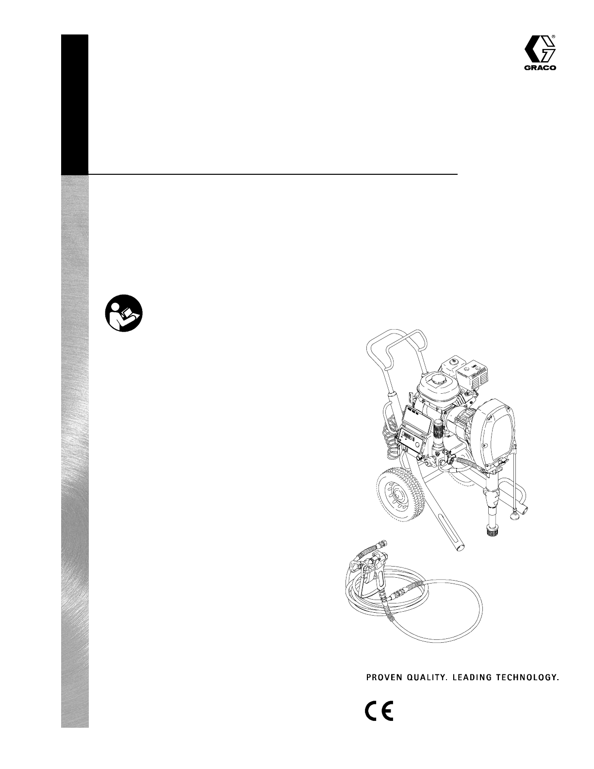
Repair Instructions
GRACO INC. P.O. BOX 1441 MINNEAPOLIS, MN 55440- 1441
Copyright 2001, Graco Inc. is registered to I.S. EN ISO 9001
GMaxR7900
Airless Paint Sprayer
3300 psi (227bar, 22.7 MPa) Maximum Working Pressure
See page 2 for models numbers.
Related Manuals
Operation 309408...............................
Displacement Pump 309277......................
Spray Gun 309639..............................
Spray Tip 309640................................
PC Board 309459...............................
Drain Valve Kit 308961...........................
Clutch Replacement Kit 309890...................
309412F
ti1833a
Important Safety Instructions
Read all warnings and instructions in this manual.
Save these instructions.

3094122
Models
Model Series Description
233718 ALo--Boy
233719 AHi--Boy
233720 ALo--Boy with RACRX tip, gun and hose
233721 AHi--Boy with RAC X tip, gun and hose
Table of Contents
Warnings and Cautions 3.........................
Maintenance 4...................................
Troubleshooting 5................................
Repair
Rollers 8......................................
Drive Housing 9................................
Cam Follower Bearings 10......................
Engine 11.....................................
Pressure Control 13............................
Displacement Pump 15.........................
Parts
Pinion Assembly 17............................
Sprayers 18...................................
Pressure Control 21............................
Tip, Gun, Hose 22..............................
Dimensions 23...................................
Technical Data 23................................
Graco Warranty 24...............................
Graco Phone Number 24..........................
309412 3
Warnings and Cautions
Warning Symbol
WARNING
This symbol alerts you to the possibility of serious
injury or death if you do not follow the instructions.
Caution Symbol
CAUTION
This symbol alerts you to the possibility of damage to
or destruction of equipment if you do not follow the
instructions.
Fluid injection and high pressure hazard: High pressure spray or
leaks can inject fluid into the body.
To help prevent injection, always:
DEngage trigger safety latch when not spraying.
DKeep clear of nozzle and leaks.
DNever spray without a tip guard.
DDo PRESSURE RELIEF if you stop spraying or begin servicing
sprayer.
DDo not use components rated less than sprayer Maximum
Working Pressure.
DNever allow children to use this unit.
If high pressure fluid pierces your skin, the injury might look like
“just a cut”, but it is a serious wound! Get immediate medical atten-
tion.
Fire and explosion: Solvent and paint fumes can ignite or
explode.
To help prevent a fire and explosion:
DUse only in an extremely well ventilated area.
DEliminate all ignition sources; such as pilot lights, cigarettes and
plastic drop cloths (static arc hazard). Do not plug or unplug
power cords or turn lights on or off in spray area.
DGround Sprayer, object being sprayed, paint and solvent pails.
DHold gun firmly to side of grounded pail when triggering into pail.
DUse only conductive airless paint hose.
DDo not use 1,1,1--trichloroethane, methylene chloride, other
halogenated hydrocarbon solvents or fluids containing such
solvents in pressurized aluminum equipment. Such use could
result in a chemical reaction, with the possibility of explosion.
DDo not fill fuel tank while engine is running or hot.
DDo not flush with gasoline.
WARNING
3094124
Maintenance
WARNING
INJECTION HAZARD
The system pressure must be manually
relieved to prevent the system from
starting or spraying accidentally. Fluid
under high pressure can be injected through the
skin and cause serious injury. To reduce the risk of
an injury from injection, splashing fluid, or moving
parts, follow the Pressure Relief Procedure
whenever you:
Dareinstructedtorelievethepressure,
Dstop spraying,
Dcheck or service any of the system equipment,
Dor install or clean the spray tip.
Pressure Relief Procedure
1. Lock gun trigger safety.
2. Turn engine ON/OFF switch to OFF.
3. Move pressure control switch to OFF and turn
pressure control knob fully counterclockwise.
4. Unlock trigger safety. Hold metal part of gun firmly
to side of grounded metal pail, and trigger gun to
relieve pressure.
5. Lock gun trigger safety.
6. Open pressure drain valve. Leave valve open until
ready to spray again.
If you suspect that the spray tip or hose is completely
clogged, or that pressure has not been fully relieved
after following the steps above, VERY SLOWLY
loosen tip guard retaining nut or hose end coupling to
relieve pressure gradually, then loosen completely.
Now clear tip or hose.
C
A
UTION
For detailed engine maintenance and specifications,
refer to separate Honda Engines Owner’s Manual,
supplied.
DAILY: Check engine oil level and fill as necessary.
DAILY: Check hose for wear and damage.
DAILY: Check gun safety for proper operation.
DAILY: Check pressure drain valve for proper opera-
tion.
DAILY: Check and fill the gas tank.
AFTER THE FIRST 20 HOURS OF OPERATION:
Drain engine oil and refill with clean oil. Reference
Honda Engines Owner’s Manual for correct oil viscos-
ity.
WEEKLY: Remove air filter cover and clean element.
Replace element, if necessary. If operating in an
unusually dusty environment: check filter daily and
replace, if necessary.
Replacement elements can be purchased from your
local HONDA dealer.
WEEKLY: Check level of TSL in displacement pump
packing nut. Fill nut, if necessary. Keep TSL in nut to
help prevent fluid buildup on piston rod and premature
wear of packings.
AFTER EACH 100 HOURS OF OPERATION:
Change engine oil. Reference Honda Engines Owner’s
Manual for correct oil viscosity.
SPARK PLUG: Use only BPR6ES (NGK) or
W20EPR--U (NIPPONDENSO) plug. Gap plug to
0.028 to 0.031 in. (0.7 to 0.8 mm). Use spark plug
wrench when installing and removing plug.
309412 5
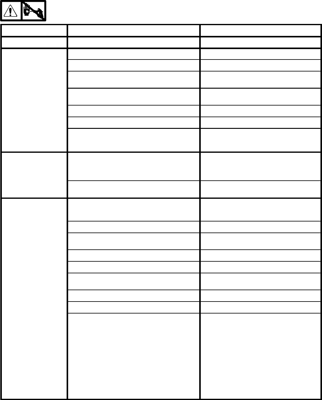
Troubleshooting
Relieve pressure;page 4.
PROBLEM CAUSE SOLUTION
E=XX is displayed Fault condition exists Determine fault correction from table, page 14.
Engine won’t start Engine switch is OFF Turn engine switch ON
Engine is out of gas Refill gas tank. Honda Engines Owner’s Manual.
Engine oil level is low Try to start engine. Replenish oil, if necessary.
Honda Engines Owner’s Manual.
Spark plug cable is disconnected or damaged Connect spark plug cable or replace spark
plug
Cold engine Use choke
Fuel shutoff lever is OFF Move lever to ON position
Oil is seeping into combustion chamber Remove spark plug. Pull starter 3 to 4 times.
Clean or replace spark plug. Start engine.
Keep sprayer upright to avoid oil seepage.
False tripping of Watch-
Dog system. EMPTY is
displayed. Pump does
not run.
Operating conditions out of WatchDog parameters Turn pressure down. Contact Graco Technical
Assistance to adjust WatchDog parameters.
Operate without WatchDog active; Manual
309408.
Low pump output. See Troubleshooting Table, Pump Outlet Low,
page 6.
Engine operates, but
displacement pump
does not operate
Error code displayed? Determine fault correction from table, page 14.
Pump switch is OFF TurnpumpswitchON.
Pressure setting is too low Turn pressure adjusting knob clockwise to
increase pressure.
Fluid filter (318) is dirty Clean filter. Page 20.
Tip or tip filter is clogged Clean tip or tip filter. Manual 309091.
Displacement pump piston rod is stuck due to dried
paint
Repair pump. Manual 309277.
Connecting rod is worn or damaged Replace connecting rod. Page 15.
Drive housing is worn or damaged Replace drive housing. Page 9.
Electrical power is not energizing clutch field Check wiring connections. Page 11.
Reference pressure control repair. Page 13.
Reference wiring diagram. Page 21.
With pump switch ON and pressure turned to
MAXIMUM, use a test light to check for power
between clutch test points on control board.
Remove 7--pin connector from control board
and measure resistance across clutch coil. At
70_F, the resistance must be between 1.7
±0.2Ω; if not, replace pinion housing.
Have pressure control checked by authorized
Graco dealer.

3094126
Troubleshooting
PROBLEM CAUSE SOLUTION
Clutch is worn, damaged, or incorrectly positioned Replace clutch. Manual 309890.
Pinion assembly is worn or damaged Repair or replace pinion assembly. Manual
309890.
Pump output is low. Strainer (89) is clogged Clean strainer. Sprayer 233716 strainer is for
use in paint only.
Piston ball (206) is not seating Service piston ball. Manual 309277.
Piston packings are worn or damaged Replace packings. Manual 309277.
O-ring (227) in displacement pump is worn or dam-
aged
Replace o-ring. Manual 309277.
Intake valve ball is not seating properly Clean intake valve. Manual 309277.
Intake valve ball is packed with material Clean intake valve. Manual 309277. Do not
leave 233716 sprayer under pressure for more
than 5 minutes when spraying texture and not
actively spraying.
Engine speed is too low Increase throttle setting. Manual 309408.
Clutch is worn or damaged Replace clutch. Manual 309890.
Pressure setting is too low Increase pressure. Manual 309408.
Fluid filter (318), tip filter or tip is clogged or dirty Clean filter. Manual 309408 or 309091.
Large pressure drop in hose with heavy
materials
Use larger diameter hose and/or reduce overall
length of hose. Use of more than 100 ft of 1/4
in. hose significantly reduces performance of
sprayer. Use 3/8 in. hose for optimum perfor-
mance (50 ft minimum).
Excessive paint leakage into
throat packing nut
Throat packing nut is loose Remove throat packing nut spacer. Tighten
throat packing nut just enough to stop leakage.
Throat packings are worn or damaged Replace packings. Manual 309277.
Displacement rod is worn or damaged Replace rod. Manual 309277.
Fluid is spitting from gun Air in pump or hose Check and tighten all fluid connections. Re--
prime pump. Manual 309408.
Tip is partially clogged Clear tip. Manual 309091.
Fluid supply is low or empty Refill fluid supply. Prime pump. Manual
309408. Check fluid supply often to prevent
running pump dry.
Pump is difficult to prime Air in pump or hose Check and tighten all fluid connections.
Reduce engine speed and cycle pump as
slowly as possible during priming.
Intake valve is leaking Clean intake valve. Be sure ball seat is not
nicked or worn and that ball seats well. Reas-
semble valve.
Pump packings are worn Replace pump packings. Manual 309277.
Paint is too thick Thin the paint according to the supplier’s
recommendations

309412 7
Troubleshooting
PROBLEM CAUSE SOLUTION
Engine speed is too high Decrease throttle setting before priming pump.
Manual 309408.
Clutch squeaks each time
clutch engages
Clutch surfaces are not matched to each other
when new and may cause noise
Clutch surfaces need to wear into each other.
Noise will dissipate after a day of run time.
High engine speed at no
l
o
a
d
Misadjusted throttle setting Reset throttle to 3700 engine rpm at no load
l
oa
d
Worn engine governor Replace or service engine governor
Gallon counter not working Bad sensor, broken or disconnected wire Check connections. Replace sensor or wire.
No display, sprayer operates Display damaged or has bad connection Check connections. Replace display.
Clutch squeaks each time
clutch engages
Clutch surfaces are not matched to each other
when new and may cause noise
Clutch surfaces need to wear into each other.
Noise will dissipate after a day of run time
Engine stalls Engine speed is to slow DIncrease throttle setting
DAdjust engine speed at no load to 3750 --
3850 rpm
Fluid filter is clogged Relieve pressure and clean filter
Too much pump friction (new pump) Reduce pressure to 3000 psi until pump wears
in
Spark plug wire is loose Reconnect wire
3094128
Rollers
Removal
1. Relieve pressure;page 4.
2. Fig. 1. Remove six cap screws (56) lock washers
(87), clip (35), and cover assembly (13).
Fig. 1
ti1860a
56
87
108
109
71
77 59
13
87
35
Note: A screw driver may be needed to pry off cover
assembly.
3. Remove dowel pins (108) and rollers (109)
Installation
1. Install rollers (109) and dowel pins (108)
2. Install cover assembly (13) with six lock washers
(87), clip (35), and cap screws (56).
309412 9
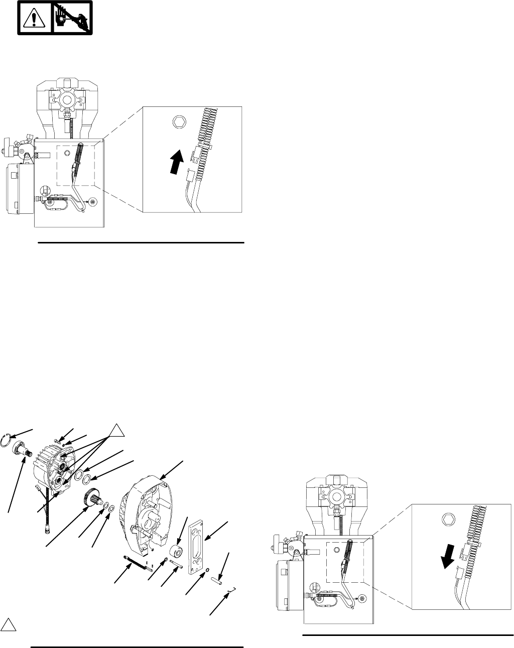
Drive Housing
Removal
1. Relieve pressure;page 4.
2. Fig. 2. Disconnect gallon counting sensor.
Fig. 2
ti1835a
3. Fig. 1. Remove six cap screws (56) lock washers
(87) and cover assembly (13).
4. Fig. 3. Remove two screws (59) and washers (87).
5. Remove four cap screws (56) lock washers (87)
from drive housing (71).
6. Lightly tap around drive housing (71) to loosen
drive housing. Pull drive housing straight off pinion
housing. Be prepared to support gear cluster
(102), which may also come out.
9046C
71
87 59
87
56
71h
71g
102 104 105
B
1
1Apply remaining grease to these areas
Fig. 3
21
71b
71c
71d
101
71a
8d
8e
Installation
1. Liberally apply bearing grease (supplied with
replacement gear cluster) to gear cluster (102),
washers (104) and (105) and to areas called out
by note 1. Use full 0.68 pint (0.32 liter) of grease
for GMax 7900.
2. Place bronze colored washer (105) and silver
colored washer (104) onto drive housing (71).
Install gear cluster (102) through washers (105)
and (104).
3. Place bronze colored washer (71g) and silver
colored washer (71h) on shaft protruding from
large shaft of drive housing (71). Align gears and
push new drive housing straight onto pinion hous-
ing and locating pins (B).
4. Install two washers (87) and screws (59).
5. Install four lock washers (87) and cap screws (56)
into drive housing (71).
6. Install cover assembly (13) with six lock washers
(87) and cap screws (56).
7. Fig. 4. Reconnect gallon counting sensor.
Fig. 4 ti1835a
30941210
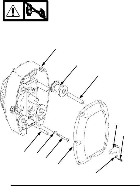
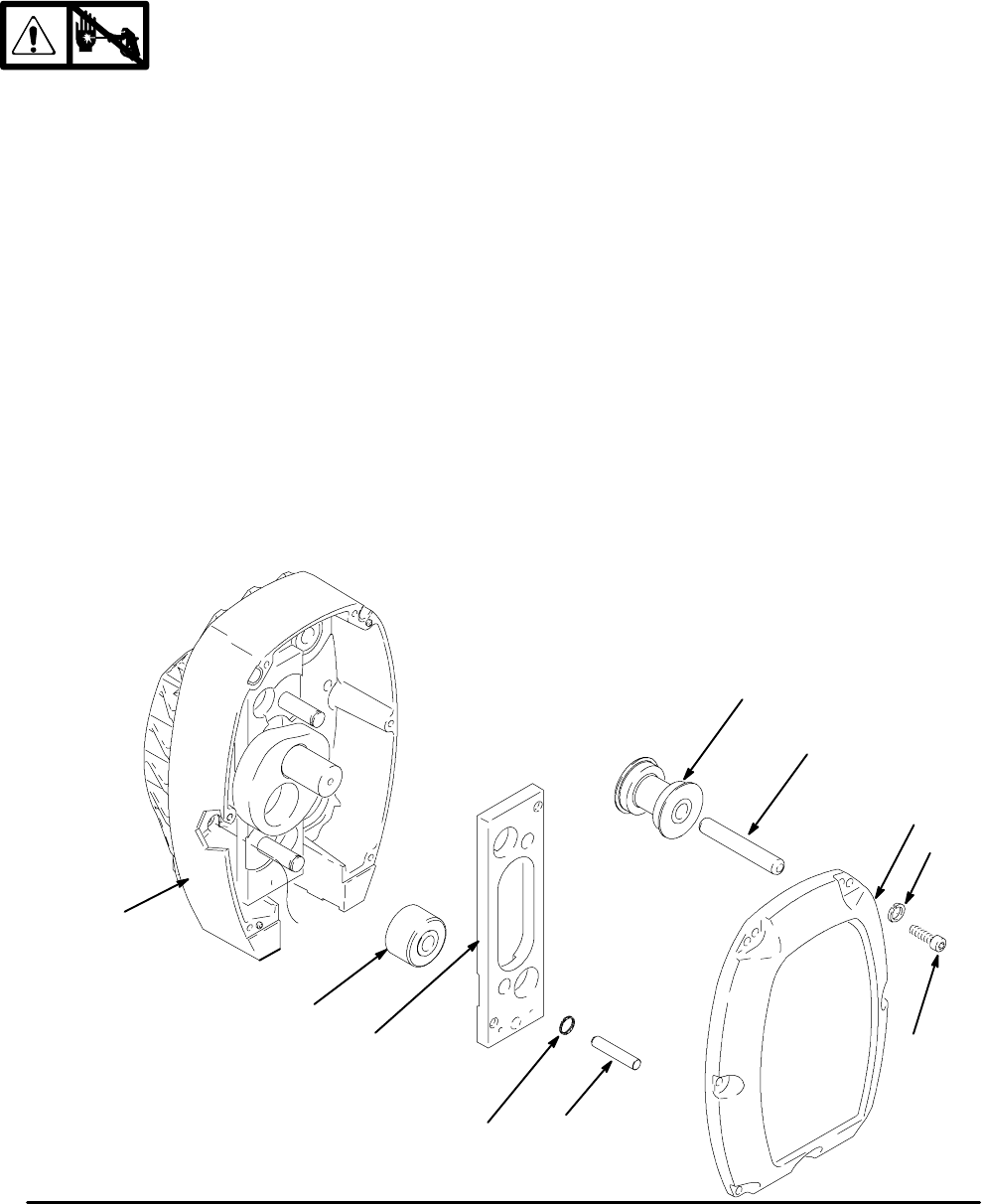
Cam Follower Bearings
Removal
1. Relieve pressure;page 4.
2. Fig. 9. Cycle pump piston rod (222) to lowest
position. Turn engine off.
3. Fig. 5. Remove six cap screws (56), lock washers
(87) and cover assembly (13).
Note: A screw driver may be needed to pry off
cover assembly.
4. Remove four dowel pins (108) and rollers (109).
5. From front, drive out pump pin (77) with a screw
driver.
6. Remove two retainer rings (71d).
7. Remove cam follower plate (71b).
Note: Two 1/2 in. x 13 bolts may be
needed to remove cam follower plates.
8. Remove two cam follower bearings (71c).
Installation
1. Install two cam follower bearings (71c).
2. Install cam follower plate (71b).
3. Install two retainer rings (71d).
4. Drive in pump pin (77) until it engages with pump
pin retaining clip (71a).
5. Install four rollers (109) and dowel
pins (108).
6. Install cover assembly (13) with six lock washers
(87) and cap screws (56).
Fig. 5
77
13
87
109
71c
71
71b
71d
108
56
9046c

309412 11
Engine
Removal
1. Remove Pinion Assembly/Rotor/Field/Pinion/
Clutch, Clamp and Clutch Housing,asin-
structed in manual 309890.
2. Fig. 6. Disconnect all necessary wiring.
3. Fig. 7. Remove two locknuts (7) and screws (6)
from base of engine.
4. Lift engine carefully and place on work bench.
NOTE: All service to the engine must be performed by
an authorized HONDA dealer.
Fig. 6
Green
1
2
To the field
To the engine
7
97
2
1
ti1835
Fig. 7
7
6
8710B
Installation
1. Lift engine carefully and place on cart.
2. Fig. 7. Install two screws (6) in base of engine and
secure with locknuts (7). Torque to 200 in-lb (22.6
NSm).
3. Fig. 6. Connect all necessary wiring.
4. Install Pinion Assembly/Rotor/Field/Pinion/
Clutch, Clamp and Clutch Housing,as
instructed in manual 309890.
30941212
On/Off Switch
Removal
1. Relieve pressure;page 4.
2. Fig. 8. Remove four screws (54) and
display/cover (52).
3. Pull display connector wings (A) open on PC board
and pull display connector out.
4. Disconnect ON/OFF switch connector (B) from PC
board.
5. Press in on two retaining tabs on each side of
ON/OFF switch (51) and remove switch.
Installation
1. Install new ON/OFF switch (51) so tabs of switch
snap into place on inside of pressure control
housing.
2. Connect ON/OFF switch connector (B) to PC
board.
3. Push display connector into PC board close dis-
play connector wings (A) on PC board.
4. Install display/cover (52) with four screws (54).
Fig. 8
52
54
ti1841a
A
51
302
122
ED
61a
61s
Z
Y
B
141
147
55
50
145
29
61p
61q
74 310
310
139
122
51
309412 13
Pressure Control
Control Board
Removal
1. Relieve pressure;page 4.
2. Fig.8. Remove four screws (54) and
display/cover (52). Pull display connector wings
(A) open on PC board and pull display connector
out.
3. Remove 2 screws (139).
4. Fig. 15. Disconnect at control board (302):
DLead (D) from potentiometer.
DLead (E) from transducer.
DLead (B) from On/Off Switch connector.
5. Fig. 8. Remove five screws (122) from control
board and ground wire screw (122).
6. Remove connector (Y) at backside of pressure
control. Remove jam nut (Z) and control board
(302).
Installation
When installing replacement control board, follow
instructions with control board to set model type.
1. Fig, 8. Install control board (302) and jam nut (Z).
Install connector (Y) at backside of pressure
control.
2. Install ground wire and control board (302) with
six screws (122).
3. Fig. 15. Connect to control board (302):
DConnect ON/OFF switch connector (B).
DLead (E) to transducer.
DLead (D) to potentiometer.
4. Fig. 8. Push display connector into PC board close
display connector wings (A) on PC board. Install
display/cover (52) with four screws (54).
Pressure Control Transducer
Removal
1. Relieve pressure;page 4.
2. Fig. 8. Remove four screws (54) and
cover (52).
3. Disconnect lead (E) from control board (302).
4. Remove two screws (141) and guard (147). Care-
fully pull transducer connector through rubber
grommet (145).
5. Remove pressure control transducer (61q) and
packing o-ring (61p) from filter housing (61e).
Installation
1. Fig. 8. Install packing o-ring (61p) and pressure
control transducer (61q) in filter
housing (61e). Torque to 30--35 ft-lb.
2. Carefully feed transducer connector through
rubber grommet (145). Install guard (147) with two
screws (141).
3. Connect lead (E) to motor control board (302).
4. Install cover (52) with four screws (54).
Pressure Adjust Potentiometer
Removal
1. Relieve pressure;page 4.
2. Fig. 8. Remove four screws (54) and
cover (52) and two screws (139).
3. Disconnect lead (D) from control board (302).
4. Loosen set screws on potentiometer knob (50) and
remove knob, shaft nut, lockwasher (310) and
pressure adjust potentiometer (310).
5. Remove spacer (74) from potentiometer (310).
Installation
1. Install spacer (74) on potentiometer (310).
2. Fig. 8. Install pressure adjust potentiometer (310),
shaft nut, lockwasher (310) and potentiometer
knob (50).
a. Turn potentiometer shaft (310) clockwise to
internal stop. Assemble potentiometer knob
(50) to strike pin on plate (29).
b. After adjustment of step a., tighten both set
screws in knob 1/4 to 3/8 turn after contact
with shaft.
3. Connect lead (D) to control board (302).
4. Install plate (29) with two screws (139).
5. Install cover (52) with four screws (54).
psi
bar
MPa
30941214
Pressure Control Repair
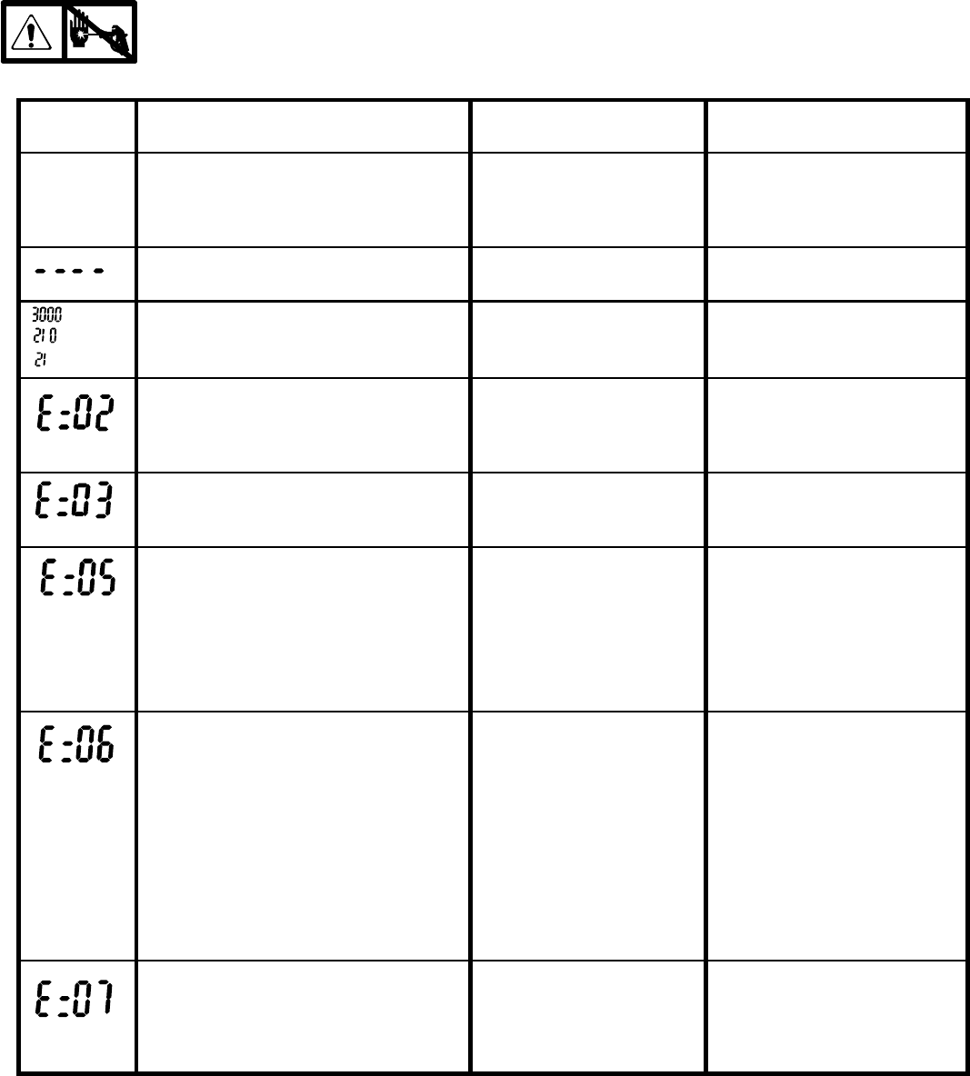
Digital Display Messages
Relieve pressure before repair;page 4. No display does not mean that sprayer is not pressurized.
DISPLAY SPRAYER
OPERATION
INDICATION ACTION
No Display Sprayer may be pressurized. Loss of power or display
not connected
Check power source. Relieve
pressure before repair or dis-
assembly. Verify display is
connected.
Sprayer may be pressurized. Pressure less than
200 psi (14 bar, 1.4 MPa)
Increase pressure as needed
Sprayer is pressurized. Power is ap-
plied. (Pressure varies with tip size and
pressure control setting.)
Normal operation Spray
Sprayer stops. Engine is running. Exceeded pressure limit Remove any filter clogs or
flow obstructions. Make sure
gun trigger is locked open if
using AutoClean valve.
Sprayer stops. Engine is running. Pressure transducer faulty,
bad connection or broken
wire.
Check transducer connections
and wire. Replace transducer
or control board, if necessary.
Sprayer stops. Engine is running. High clutch current 1. Check clutch 7--pin bulk-
head connector. Clean
contacts.
2. 1.7 ±0.2Ωacross clutch
field at 70_F
3. Replace clutch field as-
sembly
Sprayer stops. Engine is running.
Display alternates E=06.
High clutch temperature 1. If clutch is new, let spray-
er cool down and then re-
start
2. Inspect clutch. Replace
clutch if there is excessive
wear.
3. Remove pump pin, sepa-
rate pinion housing from
clutch housing. Rotate
rotor clockwise to check
for excessive drag.
Sprayer stops. Engine is running. Pressure greater than
2000 psi (138 bar, 14 MPa)
while in Flush Timer Mode
Chase paint from lines before
running in flush timer mode.
Make sure spray gun is trig-
gered and prime valve is open
when using AutoClean
After a fault, follow these steps to restart sprayer:
1. Correct fault condition
2. Turn sprayer OFF
3. Turn sprayer ON
309412 15
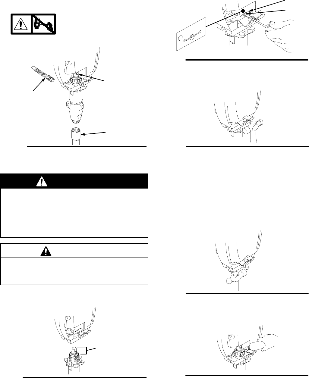
Displacement Pump
Removal
See manual 309277 for pump repair instructions.
1. Flush pump.
2. Fig. 9. Cycle pump with piston rod (222) in lowest
position.
3. Relieve pressure;page 4.
4. Fig. 9. Remove suction tube (30) and hose (33).
9024B
Fig. 9
222
33
30 9024C
5. Fig. 10. Use screwdriver to push out pump
pin (101).
Fig. 10
101
71a
Detail A 9019B
6. Fig. 11. Loosen locknut by hitting firmly with a
20 oz (maximum) hammer. Unscrew pump.
9022A
Fig. 11
Repair
Installation
WARNING
If pin works loose, parts could break off due to
force of pumping action. Parts could project
through the air and result in serious injury or prop-
erty damage. Make sure pin (101) and retaining
clip (71a) are properly installed. See Detail A. Fig.
10.
C
A
UTION
If the pump locknut loosens during operation, the
threads of the bearing housing will be damaged.
Make sure locknut is properly tightened.
1. Fig. 12. Pull piston rod out 1.0 in. Screw in pump
until holes in housing plates and piston rod align.
Fig. 12
1.0 in.
9020A
2. Fig. 10. See Detail A. Push pin (101) into hole
until retaining clip (71a) snaps over pin.
Fig. 13. Screw jam nut down onto pump until nut
stops. Screw pump up into pump plate until it stops.
Back off pump one full turn and align pump outlet to
back. Tighten jam nut by hand, then tap 1/8 to 1/4 turn
with a 20 oz (maximum) hammer to approximately 75
±5ft--lb(102N¡m).
9021A
Fig. 13
Fig. 14. Fill packing nut with Graco TSL until fluid flows
onto the top of seal.
Fig. 14 9023A
30941216
Displacement Pump
Pump Pin Clip
Removal
1. Remove pump (85).
2. Remove two bolts (107), washers (79), pump
bracket (110), pail hook (90) and shield (113).
3. Fig. 10. Remove clip (71a).
Installation
1. Fig. 10. Install clip (71a).
2. Install shield (113), pail hook (90) and pump brack-
et (110) with two washers (79) and bolts (107).
Torque bolts to 40 ft-lb (54 NSm).
3. Install pump (85).
309412 17
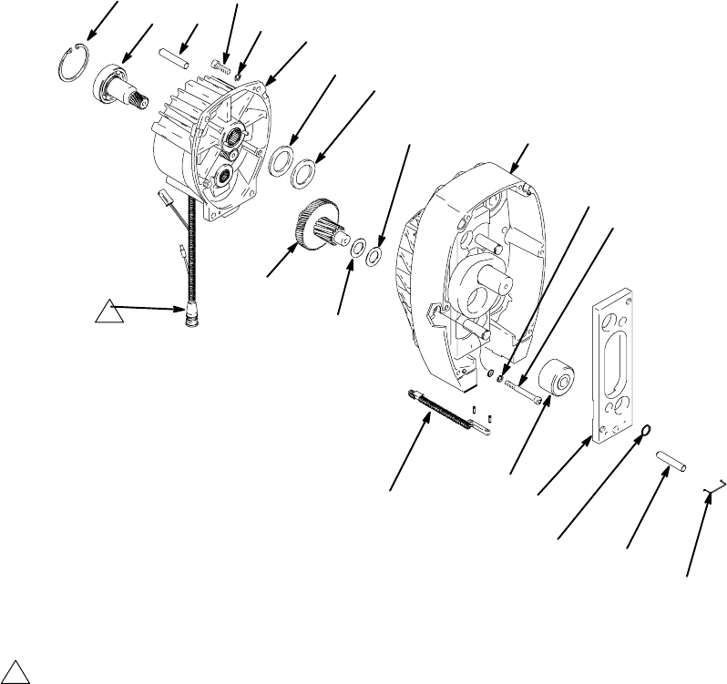
Parts List & Drawing -- Pinion Assembly
Ref No. 8 and 71
Ref No. 8: Pinion Housing Assembly 245400 Ref No. 71: Drive Housing Assembly 245444
Ref
No. Part No. Description Qty
Ref
No. Part No. Description Qty
8a 245266 PINION HOUSING, COIL 1
8b 105489 PIN 2
8d 241114 PINION SHAFT
8e 112770 RETAINING RING, large
71 DRIVE HOUSING 1
71a 194060 RETAINING CLIP, pump pin 1
71b 193656 CAM FOLLOWER PLATE 1
71c 114691 CAM FOLLOWER BEARING 2
71d 114828 RETAINER CLIP 2
71g 114697 WASHER 1
71h 114698 WASHER 1
101 195523 PIN 1
56 (Ref)
87 (Ref)
71
71h71g
102 (Ref)
8a
104 (Ref)
87 (Ref)
59 (Ref)
1
1Pinion housing/coil assembly (8a) includes clutch field and all bearings, pins and o-rings
101
105 (Ref)
8d
8e
71a
71d
71c
71b
9046C
21 (Ref)
8b
30941218
34
45
97 7
DETAIL A
BOTTOM VIEW
ti1831a
119
140
104
102
21
84
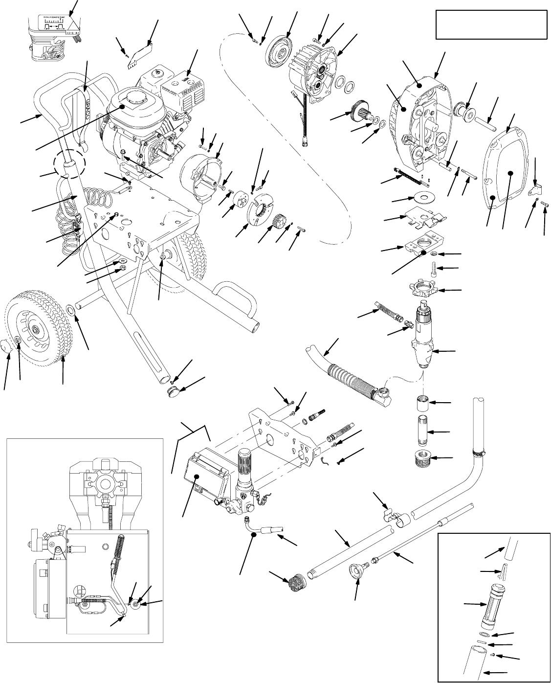
Parts Drawing -- Sprayers
103
85
107
79
110
113
77
68
13
76 87 56
108
109
*71
65,
66
105
8
87
56
1b
42
88
98
REF 49
81
49
92
16
27
31
32
32
4
64
28
94
41
124 123
132
9
100
44
42
23
1a
3
36, 86
42
26
24
42
70
57
DETAIL A
Ref 28
7
6
60
35
59
87
38
39
92
43
10
5
128
Ref 119
96
27
37 139
139
44
95
34 69
See page 20 for parts
11
142
40
67
33
*See Pinion Assembly Parts
List for more information.
309412 19
Parts List
Models 233718, 233719
Ref.
No. Part No. Description Qty.
Ref.
No. Part No. Description Qty.
1 241113 CLUTCH, ASSEMBLY
includes 1a, 1b, 23, 42, 44, 88, 1
1a ARMATURE, clutch 1
1b ROTOR 1
3 193680 COLLAR, shaft 1
4 114530 ENGINE, gas, 5.5 HP, Honda 1
5 183350 WASHER 2
6 110837 SCREW, flange, hex 2
7 110838 NUT, lock 2
8 245400 PINION ASSEMBLY; Parts page 17 1
9 193682 PLUG, tube 2
10 191084 SLEEVE, cart 2
11 114271 STRAP, retaining 1
13 241536 COVER, assembly 1
16 241920 DEFLECTOR, threaded 1
21 116806 SWITCH, reed w/conn 1
24 193531 CLUTCH HOUSING 1
26 183401 KEY, parallel 1
27 246331 HOSE, drain, Lo--Boy 1
244240 HOSE, drain, Hi--Boy 1
28 245164 FRAME, cart GMAX 7900 1
31 113084 RIVET, blind 2
32 192014 PLATE, indicator 1
33 113802 SCREW 1
34 108851 WASHER 2
35 197124 CLIP 1
36 108842 SCREW 4
37 198904 SCREW, #8 2
38 114967 COUPLING, Hi--Boy only 1
39 198122 TUBE, Hi--Boy only 1
40 114678 GROMMET 1
41 104811 CAP, hub 2
42 105510 WASHER, lock, spring (hi-clr) 15
43 112827 BUTTON, snap 2
44 108803 SCREW, hex, socket head 6
45 114687 CLIP 1
49 245249 TUBE, suction, 30 gal (assembly) 1
56 101864 SCREW, cap sch 10
57 196670 LABEL, crtl box cover 1
59 114693 SCREW, cap, socket hd 2
60 290228 LABEL, caution 1
64Y194126 LABEL, warning 1
65Y194127 LABEL, warning 1
66Y194317 LABEL, danger, English 1
67Y195119 LABEL, warning tag 1
68Y195519 LABEL, caution 1
69Y192840 LABEL, warning 1
70 100644 SCREW, cap, sch 5
71 245444 DRIVE HOUSING; Parts page 17 1
76 198653 LABEL, identification 1
77 195523 PIN, PUMP 1
79 100018 WASHER, lock, spring 2
81 196723 CLIP, spring, Lo--Boy only 1
84 193394 NUT, retaining 1
85 246257 DISPLACEMENT PUMP;
Manual 309277 1
86 100214 WASHER, lock 4
87 104008 WASHER, lock, spring 12
88 101682 SCREW, cap, sch 4
92 189920 STRAINER 1
94 237686 CLAMP, grounding assy 1
95 112798 SCREW, thread form, hex hd 1
96 108795 SCREW, mach, pnh 4
97 240997 CONDUCTOR, ground 4
98 162485 FITTING, nipple, adapter 3
100 114984 SCREW, tapping, phil pan hd 2
102 241539 GEAR, combination 1
103 241540 REPAIR KIT, HOOK, PAIL
(includes item 113) 1
104 114699 WASHER, thrust 1
105 114672 WASHER, thrust 1
107 110343 SCREW, cap, sch. 2
108 114695 PIN, dowel 4
109 241322 ROLLER, assembly 4
110 194118 BRACKET, pump 1
113 195377 SHIELD, paint 1
119 245245 HANDLE, cart 1
123 198720 WHEEL, semi-pneumatic 12 in. 2
124 198723 AXLE, clip 2
128 108068 PIN, spring straight 2
132 116891 WASHER 2
139 112774 SCREW, machine 1
140 198847 HOSE, coupled 1
141 109575 SCREW, threadforming 2
YReplacement Danger and Warning labels, tags, and cards
are available at no cost.
30941220
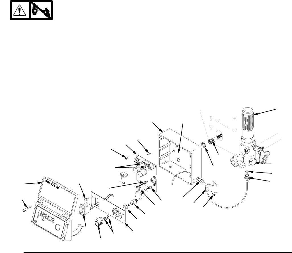
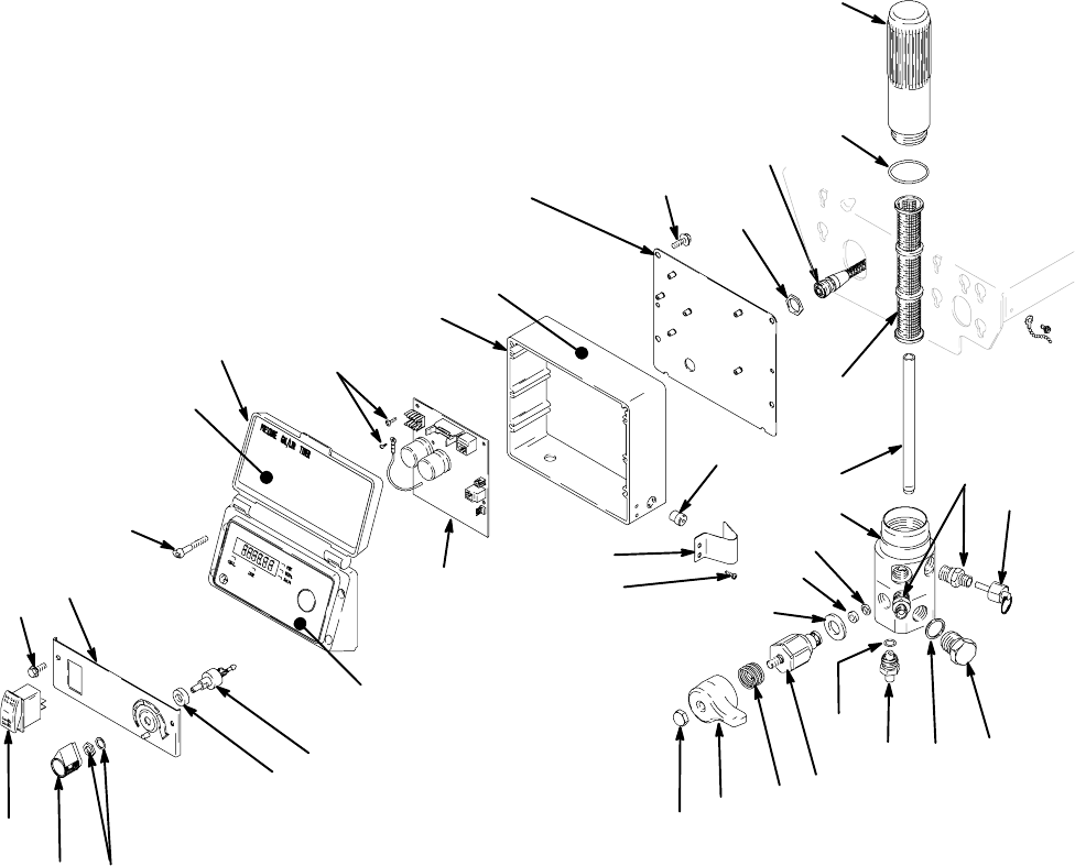
Parts Drawing -- Sprayer
61n 61m 61k
310
74
55
147
141
122
302
51
29
310
50
51
302a
61d
61e
145
61c
61b
61a
Ref 70
150
54
61j
61p
61f
139
139
52
61h
61g
61s
61q
22
61r
143
151
ti1838a
152
309412 21
Parts List -- Sprayer
REF
NO. PART NO. DESCRIPTION QTY
REF
NO. PART NO. DESCRIPTION QTY
22 162485 ADAPTER 2
29 198553 PANEL, control 1
50 116167 KNOB, potentiometer 1
51 116752 SWITCH, rocker, (spst) 1
52 245393 DIGITAL DISPLAY 1
Includes 54, 57, 151, 152
53 198534 PLATE, control 1
54 116252 SCREW, #8 taptite, phil 4
55 198548 HOUSING, control 1
FILTER, fluid 1
61 245396 KIT, repair, filter 1
(includes 61a--61s)
61a 196675 BOWL, filter 1
61b 104361 O-RING 1
61c 244067 STRAINER, mesh, 60 1
61d 196786 TUBE, diffuser 1
61e 245401 KIT, repair, filter base 1
61f 193710 SEAL, valve 1
61g 193709 SEAT, valve 1
61h 114797 GASKET 1
61j 245103* VALVE 1
61k 114708 SPRING, compression 1
61m 194102 HANDLE, valve 1
61n 114688 NUT, cap, hex hd 1
61p 111457 O-RING 1
61q 243222 TRANSDUCER, pressure control 1
includes 61p
61r 197055 GASKET, plug 1
61s 196781 PLUG, AutoClean 1
74 198650 SPACER, shaft 1
122 114331 SCREW, pnhd 6--32 6
133 109575 SCREW, threadformer 2
139 112774 SCREW, mach 4
143 245475 PLUG, packless 1
145 114296 BUSHING, step 1
147 198994 GUARD, transducer 1
150Y189246 LABEL, warning 1
151 198884 LABEL, instruction, GMax 1
152 198648 LABEL, GMax, LCD 1
302 245394 BOARD, PC 1
Includes 302a
302a NUT, nylon 1
310 241443 POTENTIOMETER, pressure control 1
* Drain valve replacement kit 245103 includes 61f, 61g, 61h,
61k, 61m, and 61n.
YReplacement Danger and Warning labels, tags, and cards
are available at no cost.
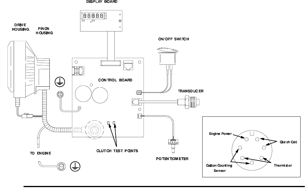
Fig. 15
Pressure Control Wiring Diagram
VIEW A VIEW A
ti1834a
71 8
52
51
61q
310
97
302
30941222
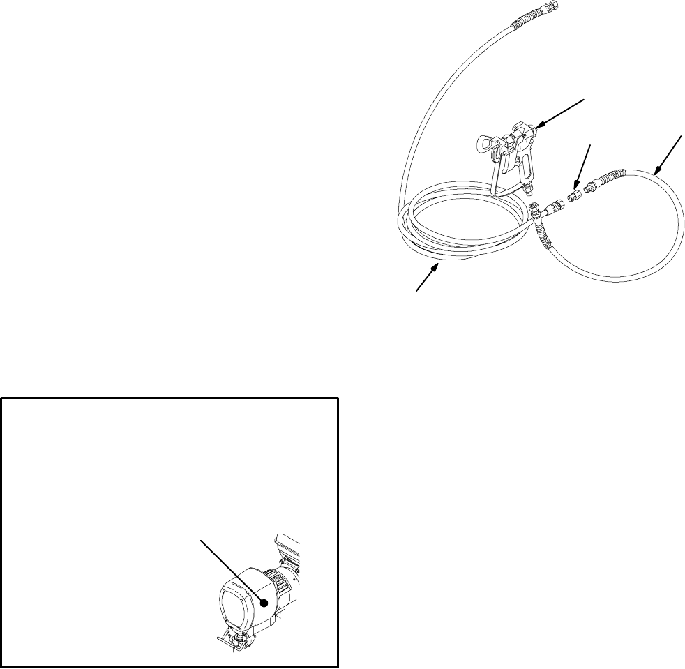
Parts List/Drawing -- Sprayers with RAC 5
Tip, Gun & Hose
Models 233720, 233721
Includes items 201 to 204
Ref
No. Part No. Description Qty
201 233719 Hi-Boy Sprayer 1
See parts list on page 19
233718 Lo-Boy Sprayer 1
See parts list on page 19
202 240797 HOSE, grounded, nylon; 3/8 in. ID; 1
cpld 3/8 npsm(fbe); 50 foot (15 m);
spring guards both ends
3300 psi (227 bar, 27.7 MPa)
203 238358 HOSE, grounded, nylon; 3/16 in. ID;
cpld 1/4 npsm(m) x 1/4 npsm(f) swivel;
3 foot (0.9 m); spring guards both ends 1
204 246220 CONTRACTOR SPRAY GUN
Includes RAC X 517--size SwitchTipt
and HandTitetGuard
See 309639 for parts 1
205 159841 ADAPTER 1
204
203
202 0160
205
Accessories
French 194931
Spanish 194932
German 194933
Greek 194934
Korean 194935
English 194125
Apply other
language here
03497A
DANGER LABELS
An English language DANGER label is on your
sprayer. If you have painters who do not read En-
glish, order one of the following labels to apply to
your sprayer. The drawing shows the best place-
ment of these labels for good visibility.
Order the labels from your Graco distributor.
Displacement Pump Repair Kits
Packing repair kits.
GMax 7900 240916
309412 23
Technical Data
Honda GX160 Engine
Power Rating @ 3700 rpm
ANSI 5.5 Horsepower.......................
DIN 6270B/DIN 6271
NA 2.9 Kw -- 4.0 Ps......................
NB 3.6 Kw -- 4.9 Ps......................
Maximum working pressure 3300 psi...............
(227 bar, 22.7 MPa)
Noise Level
Sound power 105 dBa.........................
per ISO 3744
Sound pressure 96 dBa........................
measured at 3.1 feet (1 m)
Cycles/gallon (liter) 69 (18)........................
Maximum delivery rating 2.1 gpm (7.9 liter/min)......
Maximum tip size 1 gun with 0. 046 in. tip..........
2 guns with 0.033 in. tip
3 guns with 0. 026 in. tip
4 guns with 0. 022 in. tip
Inlet paint strainer 16 mesh (1190 micron)...........
stainless steel screen, reusable
Outlet paint filter 60 mesh (250 micron).............
stainless steel screen, reusable
Pump inlet size 3/4 in. npt (m)......................
Fluid outlet size 3/8 npsm from fluid filter............
Wetted parts zinc-plated carbon steel,..............
PTFE, Nylon, UHMW polyethylene,
Vitonr,Delrinr, leather, aluminum, tungsten carbide,
nickel and zinc-plated carbon steel, stainless steel,
chrome plating, PEEK
NOTE: Delrinr,PTFE,Vitonrare trademarks of the DuPont
Company.
Dimensions
Model 233718, 233720
Lo-Boy Cart without hose or gun
Weight (dry, without packaging) 180 lb (82.1 kg).....
Height 41 in. (104.1 cm)..........................
Length 39 in. (99.1 cm)...........................
Width 22 in. (55.9 cm)............................
Model 233719, 233721
Hi-Boy without hose or gun
Weight (dry, without packaging) 175 lb (79.4 kg).....
Height 41 in. (104.1 cm)..........................
Length 39 in. (99.1 cm)...........................
Width 22 in. (55.9 cm)............................

30941224
Graco Standard Warranty
Graco warrants all equipment manufactured by Graco and bearing its nameto be free from defects inmaterial andworkmanship onthe
date of sale by an authorized Graco distributor to the original purchaser for use. With the exception of any special,extended, or limited
warranty published by Graco, Graco will, for a period of twelve months from the date of sale, repair or replace any part of the equipment
determined by Graco to be defective. This warranty applies only when the equipment is installed, operated and maintained in accor-
dance with Graco’s written recommendations.
This warranty does not cover, and Graco shall not be liable for general wear and tear, or any malfunction, damage or wear caused by
faulty installation, misapplication, abrasion, corrosion, inadequate or improper maintenance, negligence, accident, tampering, or sub-
stitution of non--Graco component parts. Nor shall Graco be liable for malfunction, damage or wear caused by the incompatibility of
Graco equipment with structures, accessories, equipment or materials not supplied by Graco, or the improper design, manufacture,
installation, operation or maintenance of structures, accessories, equipment or materials not supplied by Graco.
This warranty is conditioned upon the prepaid return of the equipment claimed to be defective to an authorized Graco distributor for
verification of the claimed defect. If the claimed defect is verified, Graco will repair or replace free of charge any defective parts. The
equipmentwill be returned to the original purchaser transportation prepaid. Ifinspection of the equipmentdoes notdisclose any defect
in material or workmanship, repairs will be made at a reasonable charge, which charges may include the costs of parts, labor, and
transportation.
THIS WARRANTY IS EXCLUSIVE, AND IS IN LIEU OF ANY OTHER WARRANTIES, EXPRESS OR IMPLIED, INCLUDING BUT
NOT LIMITED TO WARRANTY OF MERCHANTABILITY OR WARRANTY OF FITNESS FOR A PARTICULAR PURPOSE.
Graco’s sole obligation and buyer’s sole remedy for any breach of warranty shall be as set forth above. The buyer agrees that no other
remedy (including, but not limited to, incidental or consequential damages forlost profits, lost sales, injury to person or property, or any
other incidental or consequential loss) shall be available. Any action for breach of warranty must be brought within two (2)years of the
date of sale.
Graco makes no warranty, and disclaims all implied warranties of merchantability and fitness for a particular purpose in connection
with accessories, equipment, materials or components sold but not manufactured by Graco. These items sold, but not manufactured
by Graco (such as electric motors, switches, hose, etc.), are subject to the warranty, if any, of their manufacturer. Graco will provide
purchaser with reasonable assistance in making any claim for breach of these warranties.
In no event will Graco be liable for indirect, incidental, special or consequential damages resulting from Graco supplying equipment
hereunder, or the furnishing, performance, or use of any products or other goods sold hereto, whether due to a breach of contract,
breach of warranty, the negligence of Graco, or otherwise.
FOR GRACO CANADA CUSTOMERS
The parties acknowledge that they have required that the present document, as well as all documents, notices and legal proceedings
entered into, given or instituted pursuant hereto or relating directly or indirectly hereto, be drawn up in English. Les parties reconnais-
sent avoir convenu que la rédaction du présente document sera en Anglais, ainsi que tous documents, avis et procédures judiciaires
exécutés, donnés ou intentés à la suite de ou en rapport, directement ou indirectement, avec les procedures concernées.
ADDITIONAL WARRANTY COVERAGE
Graco does provide extended warranty and wear warranty for products described in the “Graco Contractor Equipment Warranty
Program”.
Graco Phone Number
TO PLACE AN ORDER, contact your Graco distributor, or call 1--800--690--2894 to identify your closest distributor.
All written and visual data contained in this document reflects the latest product information available at the time of publication.
Graco reserves the right to make changes at any time without notice.
MM 309412
Graco Headquarters: Minneapolis
International Offices: Belgium, China, Japan, Korea
GRACO INC. P.O. BOX 1441 MINNEAPOLIS, MN 55440--1441
www.graco.com
PRINTED IN USA 309412E 1/2002 Rev. 08/2009
