Graco 309868D 3 1 Mini Fire Ball 225 Oil Pump Users Manual
309868D to the manual e6f5d76d-ab2d-4184-89a4-1c72db72aaaa
2015-04-02
: Graco Graco-309868D-3-1-Mini-Fire-Ball-225-Oil-Pump-Users-Manual-686374 graco-309868d-3-1-mini-fire-ball-225-oil-pump-users-manual-686374 graco pdf
Open the PDF directly: View PDF ![]() .
.
Page Count: 18

For non-corrosive and non-abrasive oils and lubricants only. For professional use only.
Not for use in explosive atmospheres.
.
Model No. 246775, Series B, Universal
Model No. 248097, Series B, Variable Length
540 psi (3.7 MPa, 37 bar) Maximum Working Pressure
180 psi (1.24 MPa, 12.4 bar) Maximum Air Input Pressure
Contents
Warnings . . . . . . . . . . . . . . . . . . . . . . . . . . . . . . . . . 2
Installation . . . . . . . . . . . . . . . . . . . . . . . . . . . . . . . . 4
Operation . . . . . . . . . . . . . . . . . . . . . . . . . . . . . . . . . 6
Troubleshooting . . . . . . . . . . . . . . . . . . . . . . . . . . . 7
Air Motor and Throat Service . . . . . . . . . . . . . . . . . 8
Displacement Pump Service . . . . . . . . . . . . . . . . 12
Parts . . . . . . . . . . . . . . . . . . . . . . . . . . . . . . . . . . . . 14
Technical Data . . . . . . . . . . . . . . . . . . . . . . . . . . . . 16
Performance Chart . . . . . . . . . . . . . . . . . . . . . . . . 16
Dimensional Drawings . . . . . . . . . . . . . . . . . . . . . 17
Mounting Hole Layout . . . . . . . . . . . . . . . . . . . . . . 17
Graco Standard Warranty . . . . . . . . . . . . . . . . . . . 18
Graco Information . . . . . . . . . . . . . . . . . . . . . . . . . 18
Important Safety Instructions
Read all warnings and instructions in this
manual. Save these instructions.
Instructions-Parts
3:1 Mini Fire-Ball®
225 Oil Pump
ti4062b
309868D
ENG
Warnings
2309868D
Warnings
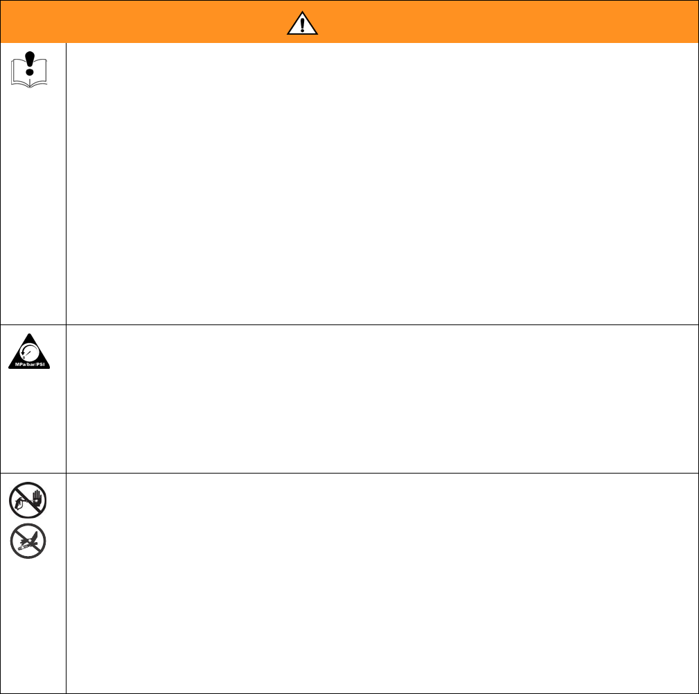
The following warnings are for the setup, use, grounding, maintenance, and repair of this equipment. The exclama-
tion point symbol alerts you to a general warning and the hazard symbol refers to procedure-specific risk. Refer back
to these warnings. Additional, product-specific warnings may be found throughout the body of this manual where
applicable.
WARNING
Equipment Misuse Hazard
Misuse can cause death or serious injury.
• Do not exceed the maximum working pressure or temperature rating of the lowest rated system
component. See Technical Data in all equipment manuals.
• Use fluids and solvents that are compatible with equipment wetted parts. See Technical Data in
all equipment manuals. Read fluid and solvent manufacturer’s warnings.
• Check equipment daily. Repair or replace worn or damaged parts immediately.
• Do not alter or modify equipment.
• Use equipment only for its intended purpose. Call your Graco distributor for information.
• For professional use only.
• Route hoses and cables away from traffic areas, sharp edges, moving parts, and hot surfaces.
• Do not use hoses to pull equipment.
• Comply with all applicable safety regulations.
PRESSURIZED EQUIPMENT HAZARD
Fluid from the gun/dispense valve, leaks, or ruptured components can splash in the eyes or on skin
and cause serious injury.
• Follow Pressure Relief Procedure in this manual, when you stop spraying and before cleaning,
checking, or servicing equipment.
• Tighten all fluid connections before operating the equipment.
• Check hoses, tubes, and couplings daily. Replace worn or damaged parts immediately.
SKIN INJECTION HAZARD
High-pressure fluid from gun, hose leaks, or ruptured components will pierce skin. This may look like
just a cut, but it is a serious injury that can result in amputation. Get immediate surgical treatment.
• Do not point gun at anyone or at any part of the body.
• Do not put your hand over the spray tip.
• Do not stop or deflect leaks with your hand, body, glove, or rag.
• Do not spray without tip guard and trigger guard installed.
• Engage trigger lock when not spraying.
• Follow Pressure Relief Procedure in this manual, when you stop spraying and before cleaning,
checking, or servicing equipment.
Warnings
309868D 3
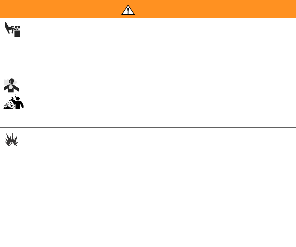
MOVING PARTS HAZARD
Moving parts can pinch or amputate fingers and other body parts.
• Keep clear of moving parts.
• Do not operate equipment with protective guards or covers removed.
• Pressurized equipment can start without warning. Before checking, moving, or servicing equip-
ment, follow the Pressure Relief Procedure in this manual. Disconnect power or air supply.
TOXIC FLUID OR FUMES HAZARD
Toxic fluids or fumes can cause serious injury or death if splashed in the eyes or on skin, inhaled, or
swallowed.
• Read MSDS’s to know the specific hazards of the fluids you are using.
• Store hazardous fluid in approved containers, and dispose of it according to applicable guide-
lines.
FIRE AND EXPLOSION HAZARD
Flammable fumes, such as solvent and paint fumes, in work area can ignite or explode. To help pre-
vent fire and explosion:
• Use equipment only in well ventilated area.
• Eliminate all ignition sources; such as pilot lights, cigarettes, portable electric lamps, and plastic
drop cloths (potential static arc).
• Keep work area free of debris, including solvent, rags and gasoline.
• Do not plug or unplug power cords or turn lights on or off when flammable fumes are present.
• Ground equipment and conductive objects. See Grounding instructions.
• Use only grounded hoses.
• Hold gun firmly to side of grounded pail when triggering into pail.
• If there is static sparking or you feel a shock, stop operation immediately. Do not use equip-
ment until you identify and correct the problem.
WARNING
Installation
4309868D
Installation
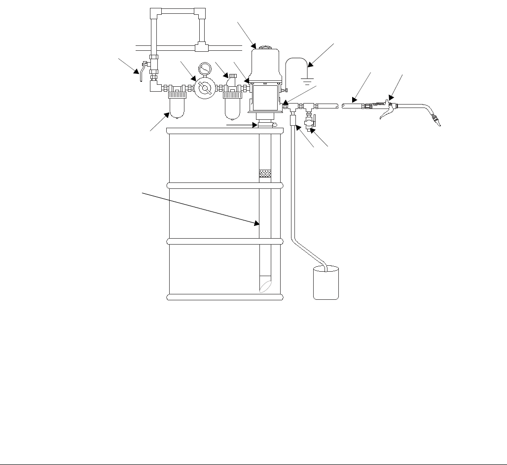
The typical stationary installation shown in FIG. 1 is only
a guide for selecting and installing a pump. It is not an
actual system design. Contact your Graco distributor for
assistance in designing a system to meet your needs.
.
A
B
C
D
E
F
G
H
L
J
K
M
Key
ABleed-type master air valve
BAir line filter
CAir regulator and gauge
DAir inlet
EGround wire
FPump
GDrain valve
HDispensing valve
JFluid hose
KThermal relief kit (235998)
LAir line lubricator
MBung adapter
NFluid outlet
PExtension tube
N
P
FIG. 1
Installation
309868D 5
Mounting the Pump
• Select a location that allows the operator easy
access to the pump and air controls, sufficient room
to change supply containers, and a secure
mounting platform.
• If you are mounting the pump directly on the supply
container, be sure it is positioned so the pump’s
intake tube is no more than 1 in. (25 mm) from the
bottom of the container. Mount the pump to the
cover or other suitable mounting device.
Grounding
Proper grounding is essential to maintaining a safe
system.
To reduce the risk of static sparking, ground the pump.
Check local electrical codes for detailed grounding
instructions for your area and equipment type. Be sure
the following equipment is properly grounded:
• Pump: See FIG. 2.
•Air and fluid hoses: Use only electrically conductive
hoses.
•Air compressor: Follow manufacturer’s
recommendations.
•Dispensing valve: Obtain grounding through con-
nection to a properly grounded fluid hose and pump.
•Fluid supply container: Follow your local code.
•Object being lubricated: Follow your local code.
•Any pails used when flushing: Use only metal,
grounded pails when flushing. Make firm
metal-to-metal contact between a metal part of the
dispensing valve and the pail. Use the lowest possi-
ble pressure.
To maintain grounding continuity when flushing or reliev-
ing pressure, always hold a metal part of the valve firmly
to the side of a grounded metal pail, then trigger the
valve.
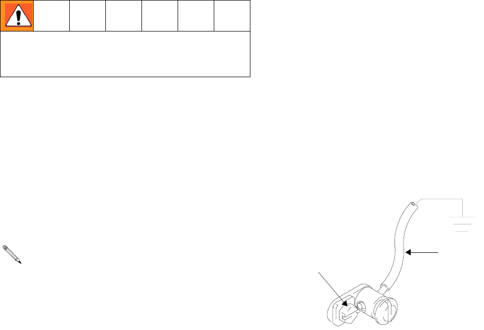
To ground the pump, remove the ground screw (Z) and
insert through the eye of the ring terminal at end of
ground wire, (Y). Fasten the ground screw back onto the
pump and tighten securely. Connect the other end of the
ground wire to a true earth ground. See FIG. 2. To order
a ground wire and clamp order Part No. 222011.
FIG. 2
Mount the pump securely so that it cannot move dur-
ing operation. Failure to do so could result in per-
sonal injury or equipment damage.
To prevent damage to the pump, remove sedi-
ment from the bottom of the container before
installing a pump in an existing container.
Y
Z
TI1052

Operation
6309868D
Operation
See FIG. 1 to identify references shown in parentheses,
i.e., (A).
Pressure Relief Procedure
1. Close the pump air regulator (C) and the bleed-type
master air valve (A), required in your system.
2. Hold a metal part of the dispensing valve (H) firmly
to a grounded metal waste container, and trigger the
valve to relieve fluid pressure.
Starting and Adjusting the Pump
1. With the air regulator (C) closed, open the
bleed-type master air valve (A).
2. Open the dispensing valve (H) into a grounded
metal waste container, making firm metal-to-metal
contact between the container and valve.
3. Open the pump air regulator (C) slowly, just until the
pump is running. When the pump is primed and all
air has been pushed out of the lines, close the dis-
pensing valve (H).
NOTE: When the pump is primed, and with sufficient air
supplied, the pump starts when the dispensing valve (H)
is opened, and shuts off when it is closed.
4. Adjust the air regulator (C) until you get sufficient
flow from dispensing valve (H). Always run the
pump at the lowest pressure necessary to get the
desired results. Do not exceed the maximum work-
ing pressure of any component in the system.
5. If your pump accelerates quickly or is running too
fast, stop it immediately and check the fluid supply. If
the supply container is empty and air has been
pumped into the lines, prime the pump and lines
with fluid, or flush it and leave it filled with a compat-
ible solvent. Be sure to eliminate all air from the fluid
lines.
6. Read and follow the instructions supplied with each
component in your system.
7. If the pump will be unattended for any period of
time, if there is an air supply interruption, or at the
end of the work shift, shut off the system and always
relieve the pressure.
This equipment stays pressurized until pressure is
manually relieved. Read PRESSURIZED EQUIP-
MENT HAZARD warnings on page 2.
Maximum working pressure of all components in the
system may not be the same. To reduce risk of over-
pressurizing any component, be sure you know the
maximum working pressure of each component.
Never exceed the maximum working pressure of the
lowest rated component in the system. Overpressur-
izing any component can result in rupture, fire, explo-
sion, property damage, and serious injury.
To determine the fluid output pressure using the air
regulator reading, multiply the ratio of the pump by
the air pressure shown on the regulator gauge. For
example:
3:1 ratio x 100 psi air = 300 psi fluid output
Limit the air pressure to the pump so that no air line
or fluid line component is overpressurized.
CAUTION
Never allow the pump to run dry of the fluid being
pumped. A dry pump will quickly accelerate to a high
speed, possibly causing pump damage. It may also get
very hot.
Troubleshooting
309868D 7
Troubleshooting
Check all other possible problems and solutions
before disassembling the pump. Before you trouble-
shoot problems using the table below, relieve the
pressure and disconnect the pump fluid line. If the
pump starts when the air is turned on again, the
fluid line, dispensing valve, etc., is clogged.
Problem Cause Solution
Pump fails to operate Inadequate air supply pressure or
restricted air lines
Increase air supply; clear
Closed or clogged dispensing valve Open; clear
Clogged fluid lines, hoses, valve, etc. Clear
Damaged air motor Service air motor
Exhausted fluid supply Refill and reprime or flush
Continuous air exhaust Worn or damaged air motor gasket,
packing, seal, etc.
Service air motor
Erratic pump operation Exhausted fluid supply Refill and reprime or flush
Pump operates, but output low
on down stroke
Held open or worn intake valve or pis-
ton packings
Clear; service
Pump operates, but output low
on up stroke
Held open or worn piston ball or piston
packings
Clear; service
Pump operates, but output low
on both strokes
Inadequate air supply pressure or
restricted air lines
Increase air supply; clear
Closed or clogged valves Open; clean
Exhausted fluid supply Refill and reprime or flush
Clogged fluid lines, hoses, valves, etc. Clear
Air Motor and Throat Service
8309868D
Air Motor and Throat Service
Before You Start
• Be sure you have all necessary parts on hand.
Pump Repair Kit 246918 includes repair parts for
the pump and air motor. Use all the parts in the kit
for the best results. Parts included in the kit are
marked with one asterisk, for example (17*), in the
text and drawings. See Parts, page 14.
• Two accessory tools should be used: Padded
Pliers, 248198, are used to grip the trip rod without
damaging its surface. Gauge, 15E796, is used to
ensure the proper clearance between the poppets
and seat of the transfer valve.
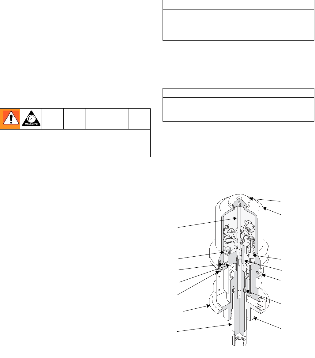
Disassembly
1. Flush the pump, and relieve the pressure.
2. Disconnect the ground wire from the grounding
screw (28a), disconnect the hoses, remove the
pump from its mounting, and clamp the air motor
base in a vise horizontally by closing the vice jaws
on the flange.
3. Use a strap wrench on the fluid cylinder (105) to
screw it out of the air motor base (28). See Parts,
page 14.
4. Pull the displacement rod (29) down as far as it will
go. See FIG. 3.
5. Using wrenches on the flats of the displacement
rod (29) and on the flats of the fluid piston (107),
unscrew the fluid piston from the displacement rod.
Remove the ball (100) from the end of the displace-
ment rod, and remove the packing o–ring (102*)
from the fluid piston. See Parts, page 14.
6. Clamp the air motor upright in the vice by closing
the vice jaws below the flange.
7. Unscrew the cylinder cap nut (39) from the top of
the air motor cylinder (35).
8. Pull up on the cylinder cap nut (39) to expose the
trip rod, grasp the trip rod with padded pliers (Part
No. 248198), and unscrew the cylinder cap nut from
the trip rod.
9. Remove the six screws (9) holding the air motor
cylinder (35) to the air motor base (28), and care-
fully pull the cylinder straight up off of the
piston (34).
10. Pull the air motor piston/displacement rod assembly
(29, 34) clear of the air motor base (28) by pulling up
on the air motor piston.
11. Remove the o–rings (13*, 103*) and u–cup
packing (16*) from the air motor base (28). Use nee-
dle–nose pliers to remove the u–cup packing from
the bottom of the air motor base.
To reduce the risk of serious injury whenever you are
instructed to relieve pressure, always follow the
Pressure Relief Procedure on page 6.
CAUTION
Do not damage the plated surface of the trip rod (40).
Damaging the surface of the trip rod can result in
erratic air motor operation. Use the special padded
pliers to grasp the rod.
CAUTION
To avoid damaging the cylinder wall, lift the cylinder
straight up off of the piston. Never tilt the cylinder
while you are removing it.
FIG. 3
39
35
32*
34
28a
16*
28
40
18*
19
13*
9
flange
29
05725B
Air Motor and Throat Service
309868D 9
12. Remove the o–ring (18*) from the air motor
piston (34).
13. Clamp the displacement rod upright in the vice by
closing the vice jaws on the flats of the displace-
ment rod.
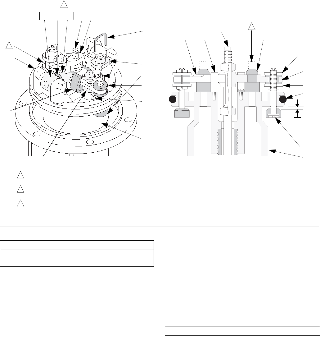
14. Use a screwdriver to push down on the trip rod
yoke (23) to snap the toggle assemblies (L) down.
See FIG. 4.
15. Remove the lockwires (25*) from the adjusting
nuts (24*) of the transfer valves. Screw the top nuts
off. Screw the valve poppet (32*) stems out of the
grommets (17*) and bottom nuts (24*). Take the
valve poppets off of the stems, and squeeze them
firmly to check for cracks.
16. Grip the toggle arms (38) with pliers. Compress the
springs (20) and swing the toggle assembly (L) up
and away from the piston lugs (M), and remove the
assembly. Check that the valve actuator (27) is sup-
ported by the spring clips (26), but slides easily into
them. See Fig. 4.
17. Remove the trip rod yoke (23), actuator (27), and
trip rod (40). Check the exhaust valve poppets (31*)
for cracks.
Clean and Service
1. Clean all the parts carefully in a compatible solvent
and inspect for wear or damage. Use all the repair
kit parts during reassembly, and replace other parts
as necessary.
2. Check the polished surfaces of the air motor
piston (34), displacement rod (29), and cylinder
wall (35) for scratches or wear. A scored rod will
cause premature packing wear and leaking.
3. Lubricate all parts with a light weight, water-resis-
tant grease.
Reassembly
1. Clamp the displacement rod (29) upright in the vice
by closing the vice jaws on the flats of the displace-
ment rod.
2. Pull the new exhaust valve poppets (31*) into the
valve actuator (27), and clip off the top parts of the
poppets (shown with dotted lines in the Cutaway
View in Fig. 4).
3. Install the new grommets (17*) in the actuator (27),
place the inlet valve poppets (32*) in the piston, and
thread the bottom valve nuts (24*) onto the stems of
the inlet valve poppets until there are a few threads
left before the threads run out.
4. Grease heavily and place the trip rod (40) in the air
motor piston (34), place the actuator (27) in the
yoke (23), and place the well–greased actuator/yoke
assembly in the piston, with the trip rod going
through the center holes of the actuator and yoke
and the stems of the inlet valve poppets (32*) going
through the grommets (17*).
5. Thread the top valve nuts (24*) onto the stems of
the inlet valve poppets (32*) until one thread of the
inlet valve poppets is exposed above the valve nuts.
6. Install the toggle pins (36) in the yoke (23), place the
toggle arm (38) ends of the toggle assembly (L)
onto the toggle pins, and snap the pivot pin (37)
ends of the toggle assembly into the piston lugs (M).
7. Measuring with the gauge (Part No.15E796), create
0.105 in. (2.7 mm) of clearance between the inlet
valve poppets (32*) and the piston seat when the
inlet valve is open. See the Cutaway View in Fig. 4.
8. Tighten the bottom valve nuts (24*) by hand. The
grommets (17*) should be slightly compressed.
To reduce the risk of pinching or amputating your fin-
gers, always keep fingers clear of the toggle
assemblies (L).
To remove the exhaust valve poppets (31*), stretch
them out and cut the end off with a sharp knife.
If you thread the valve nuts too far down onto the
poppets, they will run off the threaded part of the
poppets.
Adjust the distance between the inlet valve poppets
and the piston seat by turning the top valve
nuts (24*).
Air Motor and Throat Service
10 309868D
9. Align the holes in the valve nuts (24*) and the slots
on the stems of the inlet valve poppets (32*). Drop
the lock wires (25*) through the holes in the valve
nuts and into the slots in the stems of the inlet valve
poppets. Pull the lock wires down tightly, and bend
the ends with pliers so that they cannot be pulled
back out of the holes.
10. Take the assembly out of the vice so that you can
move it around for steps 11 and 12.
11. Grease and install the new o–rings (13*, 18*, 103*).
12. Install the new u–cup packing (16*) through the bot-
tom of the air motor base, with the lips facing toward
the bottom of the pump.
13. Slide the displacement rod (29) down through the
packings, and lower the air motor piston (34) into
the air motor base (28).
14. Clamp the air motor upright in the vice by closing
the vice jaws below the flange.
15. Carefully lower the air motor cylinder (35) straight
down onto the piston assembly (34). Tighten the six
screws (9) holding the air motor cylinder to the air
motor base (28).
FIG. 4
0.105 in.
(2.7 mm)
Turn wires up.
Push toggles (L) in and then up.
Cut off tops of poppets as indicated by dotted lines.
1
2
3
32*
24*
25*
23
40
38
20
37
M
17*
27
24*
34
17*
26 40
31*
24*
18*
32*
34
L
24*
1
2
3
Cutaway View
04118 04119
26
31*
CAUTION
Never re-use the old lock wires. They will get brittle
and break easily from too much bending.
CAUTION
To avoid damaging the cylinder wall, lower the cylinder
straight down onto the piston. Never tilt the cylinder as
it is being lowered.
Air Motor and Throat Service
309868D 11
16. Pull the trip rod (40) so it is sticking up out of the air
motor cylinder (35).
17. Grip the trip rod (40) with padded pliers, screw the
cylinder cap nut (39) onto the trip rod, push the cyl-
inder cap nut down, and screw it into the top of the
cylinder.
18. Place the piston ball (100) in the displacement
rod (29).
19. Clean the threads of the fluid piston (107), apply
Loctite® to the threads, install the new packing
o–ring (102*) on the fluid piston, and thread the fluid
piston onto the displacement rod (29).
20. Clamp the flats of the fluid piston (107) in a vice,
and torque the displacement rod (29) to the piston
to 40 to 60 ft–lb (54 to 81 N•m).
21. Clamp the air motor base (28) in a vise horizontally
by closing the vice jaws on the flange.
22. Use a strap wrench to screw the displacement
pump cylinder (105) to the air motor base (28), and
torque to 40 to 60 ft–lb (54 to 81 N•m).
23. Before remounting the pump, connect an air hose
and run the air motor slowly, starting with just
enough air pressure to make the air motor run, and
make sure that it operates smoothly.
24. Reconnect the ground wire before you resume regu-
lar pump operation.
You may have to hold the unit upside down to
shake the trip rod loose.
CAUTION
Do not damage the plated surface of the trip rod (40).
Damaging the surface of the trip rod can result in
erratic air motor operation. Use the special padded
pliers to grasp the rod.
Never operate the pump with the warning plate (47)
or the identification plate (46) removed. These plates
protect your fingers from getting pinched or ampu-
tated by moving parts in the air motor.

Displacement Pump Service
12 309868D
Displacement Pump Service
Be sure you have all necessary parts on hand. Pump
Repair Kit 246918 includes repair parts for the pump
and air motor. Use all of the parts in the kit for the best
results. Parts included in the kit are marked with one
asterisk, for example (13*), in the text and drawings. See
Parts, page 14.
1. Flush the pump and relieve the pressure.
2. Disconnect the hoses, remove the pump from its
mounting, and clamp the air motor base in a vise
horizontally by closing the vice jaws on the flange.
3. Unscrew the intake valve housing (106) from the
fluid cylinder (105). Disassemble the intake valve
(see Parts, page 14). Clean and inspect the parts
for wear or damage, and replace parts as needed.
Be sure to check the o-ring (104*). Unless further
intake valve service is needed, reassemble and
reinstall, using liquid sealant on the male threads.
4. Use a strap wrench on the fluid cylinder (105) to
screw it out of the air motor base (28). Carefully
inspect the smooth inner surface of the cylinder for
scoring or irregular surfaces. Such damage causes
premature packing wear and leaking, so replace the
part if it is damaged.
5. Using wrenches on the flats of the displacement
rod (29) and on the flats of the fluid piston (107),
unscrew the fluid piston from the displacement rod.
6. Take the piston ball (100) out of the displacement
rod (29), and take the packing o-ring (102*) off of
the fluid piston (107).
7. Clean and inspect the parts. Use all the repair kit
parts during reassembly, and replace other parts as
necessary.
8. Place the piston ball (100) in the displacement
rod (29).
9. Install the new packing o-ring (102*) on the fluid
piston (107).
10. Clamp the flats of the fluid piston (107) in a vice and
torque the displacement rod (29) to the piston to
40 to 60 ft-lb (54 to 81 N•m).
11. Clamp the air motor base (28) in a vise horizontally
by closing the vice jaws on the flange.
12. Use a strap wrench to screw the fluid cylinder (105)
to the air motor base (28), and torque to
40 to 60 ft-lb (54 to 81 N•m).
13. If you disconnected the ground wire, reconnect it
before you resume regular pump operation.
To reduce the risk of serious injury whenever you are
instructed to relieve pressure, always follow the
Pressure Relief Procedure on page 6.

Displacement Pump Service
309868D 13
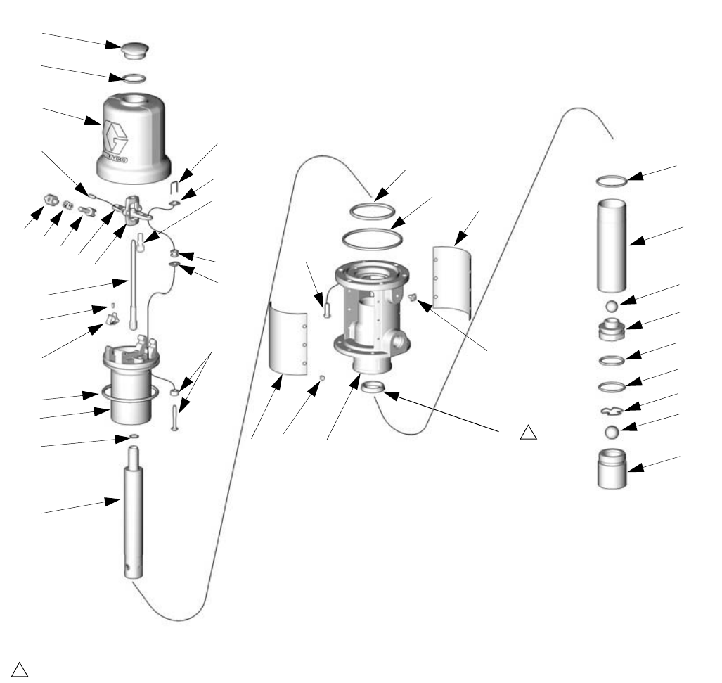
Parts
14 309868D
Parts
39
15
35
25*
24*
17*
24*
32*
105
29
34
18*
26
10
40
23
38
20
37
36 13*
19 46
28a
9
47 728 16*
103*
100
107
102*
104*
27
31*
30
108
101
106
1
1Lips face down.
Air Motor
Pump
TI4016b
Parts
309868D 15
Model No. 246775, Series B, Universal
Model No. 248097, Series B, Variable Length
Air Motor Pump
*Included in Pump Repair Kit 246918.
** Use gap adjustment tool 15E796 (also included in
Repair Kit 246918) to ensure correct gap setting for
poppets.
Ref.
No. Part No. Description Qty.
7 100078 SCREW, thread forming, hex head
8-32 x 3/8 in. 12
9 101578 CAPSCREW, hex head,
8-32 x 3/8 in. 6
10 118718 SCREW, machine 2
13* 113347 O-RING, buna-N 1
15 156698 O-RING, buna-N 1
16* 118106 PACKING, u-cup 1
17* 118107 GROMMET, lower valve 2
18* 118108 PACKING, o-ring 1
19 118109 PACKING, square 1
20 118111 SPRING, compression, helical 1
23 15C245 YOKE, rod, trip 1
24* 15C246 NUT, valve 4
25* 15C247 WIRE, lock 2
26 15C248 CLIP, spring 2
27 15C249 ACTUATOR, valve 1
28 253580 BASE, motor, air (includes 28a) 1
28a 116343 SCREW, grounding 1
29 15C252 ROD, displacement, mp 1
30 15C266 GASKET, copper 1
31* 15C267 POPPET, valve, exhaust 2
32* 248211 POPPET, valve, inlet** 2
34 15W205 PISTON, motor, air 2-1/4” 1
35 15C274 CYLINDER, motor, air 1
36 15C275 PIN, toggle 2
37 15C276 PIN, pivot 2
38 15C277 ARM, toggle 2
39 15C278 NUT, cap, cylinder 1
40 15C279 ROD, trip 1
46 246782 PLATE, muffler, serial number 1
47 246783 PLATE, muffler, warning 1
Ref.
No. Part No. Description Qty.
100 100400 BALL, piston, metallic, 3/4 in. 1
101 100279 BALL, metallic, 7/8 in. 1
102* 107227 O-RING, buna-N 1
103* 107306 O-RING, fluoroelastomer 1
104* 157195 O-RING, buna-N 1
105 15C499 CYLINDER, fluid 1
106 15C500 HOUSING, valve, intake 1
107 15C501 PISTON, fluid 1
108 15C533 RETAINER, ball 1
109 15C502 TUBE, extension, variable length,
Model 248097 only, (not shown) 1
110 222308 ADAPTER, bung, Model 248097
only, (not shown) 1
Technical Data
16 309868D
Technical Data
(Data measured with 10 weight oil at 70°F (21°C)
Fluid to air ratio......................................................... 3:1
Cycles/gallon (cycles/liter) ............................ 43.5 (11.4)
Fluid flow @80 cpm (gpm/lpm)....................... 1.84 (7.0)
Pumping distance guideline.......... up to 250 ft. (76.2 m)
Maximum fluid pressure ........ 540 psi (3.7 MPa, 37 bar)
Air motor effective diameter.............. 2.25 in. (57.2 mm)
Air operating range ............... 40-180 psi (0.28-1.2 MPa,
2.8-12 bar)
Approx. air consumption and fluid flow @100 psi air and
80 cpm .....8.5 scfm @2.1 gpm (.241 m3/min @7.9 lpm)
Dry suction lift (feet of water) ..................................... 23
Wetted materials ........... steel, polyurethane, aluminum,
buna-N, Rulon®
Air inlet port size .........................................3/8 in. npt(f)
Fluid inlet port size......................................1.5 in. npt(f)
Fluid outlet port size....................................1/2 in. npt(f)
Sound pressure (measured 1 meter from unit)..77.8 dB
Sound pressure (ISO 9614-2)............................85.6 dB
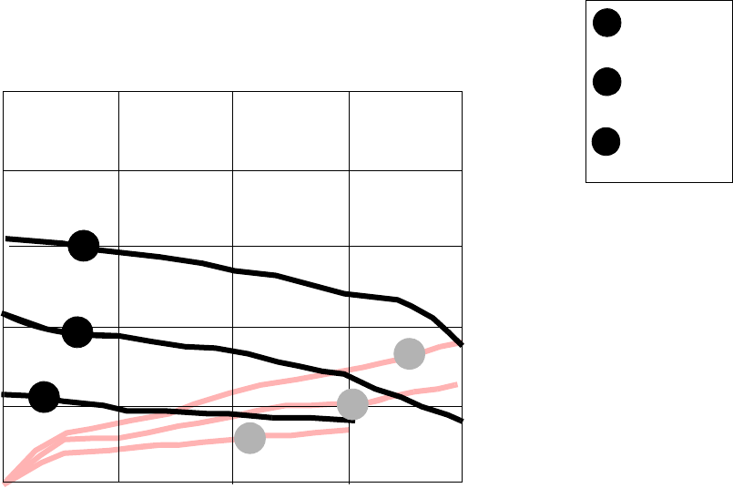
Performance Chart
A
B
C
A
B
C
AIR CONSUMPTION
FLUID OUTLET PRESSURE
TEST FLUID: No 10 Weight Oil
psi
(bar)
500
(31.4)
400
(21)
300
(10.4)
200
(5.2)
0
gpm
(lpm)
0134
40
(0.3)
24
(0.23)
16
(0.17)
8
(0.12)
0
(0.08)
scfm
(m3 / min)
100
(5.2)
2
43.5
32
(0.23)
A
B
C
=
100 psi
(6.9 bar)
=
70 psi
(4.8 bar)
=
40 psi
(2.8 bar)
Inlet Air Pressures:
Flow Rate
cycles/min
87 130.5 174
Dimensional Drawings
309868D 17
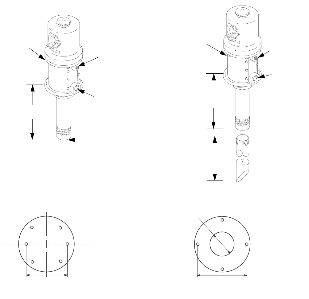
Dimensional Drawings
4.250 in. (10.8 cm) bolt circle
0.281 in. (7.1 mm) diameter clearance holes
Mounting Hole Layout
4.250 in. (10.8 cm) bolt circle
0.266 in. (6.7 mm) diameter clearance holes
Pump Base
Order gasket 15R881 for sealed tank/drum mounting.
2.518 in.
(6.4 cm) dia.
grounding
screw
1/2 in. npt(f)
fluid outlet
3/8 in. npt(f)
air inlet
8.9 in.
(20 cm)
40.68 in. (103.33
cm) drop tube is
cut to length
Model 246775
Universal
Overall Length: 18.9 in. (48 cm)
1/2 in. npt(f)
fluid outlet
3/8 in. npt(f)
air inlet
8.9 in.
(20 cm)
Grounding
screw
05750
1-1/2 in. npt
Model 248097
Variable length
Overall Length: 59.2 in. (150.4 cm)

All written and visual data contained in this document reflects the latest product information available at the time of publication.
Graco reserves the right to make changes at any time without notice.
Original instructions. This manual contains English. MM 309868
Graco Headquarters: Minneapolis
International Offices: Belgium, China, Japan, Korea
GRACO INC. P.O. BOX 1441 MINNEAPOLIS, MN 55440-1441
Copyright 2004, Graco Inc. is registered to ISO 9001
www.graco.com
Revised 03/2010
Graco Standard Warranty
Graco warrants all equipment referenced in this document which is manufactured by Graco and bearing its name to be free from defects in
material and workmanship on the date of sale to the original purchaser. With the exception of any special, extended, or limited warranty published
by Graco, Graco will, for a period of twelve months from the date of sale, repair or replace any part of the equipment determined by Graco to be
defective. This warranty applies only when the equipment is installed, operated and maintained in accordance with Graco’s written
recommendations.
This warranty does not cover, and Graco shall not be liable for general wear and tear, or any malfunction, damage or wear caused by faulty
installation, misapplication, abrasion, corrosion, inadequate or improper maintenance, negligence, accident, tampering, or substitution of
non-Graco component parts. Nor shall Graco be liable for malfunction, damage or wear caused by the incompatibility of Graco equipment with
structures, accessories, equipment or materials not supplied by Graco, or the improper design, manufacture, installation, operation or
maintenance of structures, accessories, equipment or materials not supplied by Graco.
This warranty is conditioned upon the prepaid return of the equipment claimed to be defective to an authorized Graco distributor for verification of
the claimed defect. If the claimed defect is verified, Graco will repair or replace free of charge any defective parts. The equipment will be returned
to the original purchaser transportation prepaid. If inspection of the equipment does not disclose any defect in material or workmanship, repairs will
be made at a reasonable charge, which charges may include the costs of parts, labor, and transportation.
THIS WARRANTY IS EXCLUSIVE, AND IS IN LIEU OF ANY OTHER WARRANTIES, EXPRESS OR IMPLIED, INCLUDING BUT NOT LIMITED
TO WARRANTY OF MERCHANTABILITY OR WARRANTY OF FITNESS FOR A PARTICULAR PURPOSE.
Graco’s sole obligation and buyer’s sole remedy for any breach of warranty shall be as set forth above. The buyer agrees that no other remedy
(including, but not limited to, incidental or consequential damages for lost profits, lost sales, injury to person or property, or any other incidental or
consequential loss) shall be available. Any action for breach of warranty must be brought within two (2) years of the date of sale.
GRACO MAKES NO WARRANTY, AND DISCLAIMS ALL IMPLIED WARRANTIES OF MERCHANTABILITY AND FITNESS FOR A
PARTICULAR PURPOSE, IN CONNECTION WITH ACCESSORIES, EQUIPMENT, MATERIALS OR COMPONENTS SOLD BUT NOT
MANUFACTURED BY GRACO. These items sold, but not manufactured by Graco (such as electric motors, switches, hose, etc.), are subject to
the warranty, if any, of their manufacturer. Graco will provide purchaser with reasonable assistance in making any claim for breach of these
warranties.
In no event will Graco be liable for indirect, incidental, special or consequential damages resulting from Graco supplying equipment hereunder, or
the furnishing, performance, or use of any products or other goods sold hereto, whether due to a breach of contract, breach of warranty, the
negligence of Graco, or otherwise.
FOR GRACO CANADA CUSTOMERS
The Parties acknowledge that they have required that the present document, as well as all documents, notices and legal proceedings entered into,
given or instituted pursuant hereto or relating directly or indirectly hereto, be drawn up in English. Les parties reconnaissent avoir convenu que la
rédaction du présente document sera en Anglais, ainsi que tous documents, avis et procédures judiciaires exécutés, donnés ou intentés, à la suite
de ou en rapport, directement ou indirectement, avec les procédures concernées.
Graco Information
For the latest information about Graco products, visit www.graco.com.
TO PLACE AN ORDER, contact your Graco distributor or call to identify the nearest distributor.
Phone: 612-623-6928 or Toll Free: 1-800-533-9655, Fax: 612-378-3590
