Graco 312359J Xm Plural Component Sprayers Users Manual Sprayers, Operation, English
2015-04-02
: Graco Graco-312359J-Xm-Plural-Component-Sprayers-Users-Manual-686268 graco-312359j-xm-plural-component-sprayers-users-manual-686268 graco pdf
Open the PDF directly: View PDF ![]() .
.
Page Count: 86
- Related Manuals
- Warnings
- Models
- Overview
- Location
- Proper Lifting of Sprayer
- Initial System Setup
- Component Identification
- Setup
- Basic Operation
- Prime
- Recirculate
- Spray
- Adjust B Machine Outlet Restriction
- Pressure Relief Procedure
- Flush Mixed Material
- Park Fluid Pump Rods
- Shutdown Entire System
- System Verification
- Empty and Flush Entire System (new sprayer or end of job)
- Download Data from USB
- Maintenance
- Alarms
- Accessories and Kits
- Appendix A
- Appendix B
- Appendix C
- Dimensions
- Pump Performance Charts
- Technical Data
- Graco Standard Warranty
- Graco Information
Operation
XM™ Plural-Component
Sprayers 312359J
For spraying two-component epoxy and urethane protective coatings in hazardous and
non-hazardous locations.
For professional use only.
Important Safety Instructions
Read all warnings and instructions in this
manual. Save these instructions.
See page 7 for model information and agency approvals.
See page 84 for maximum working pressure.
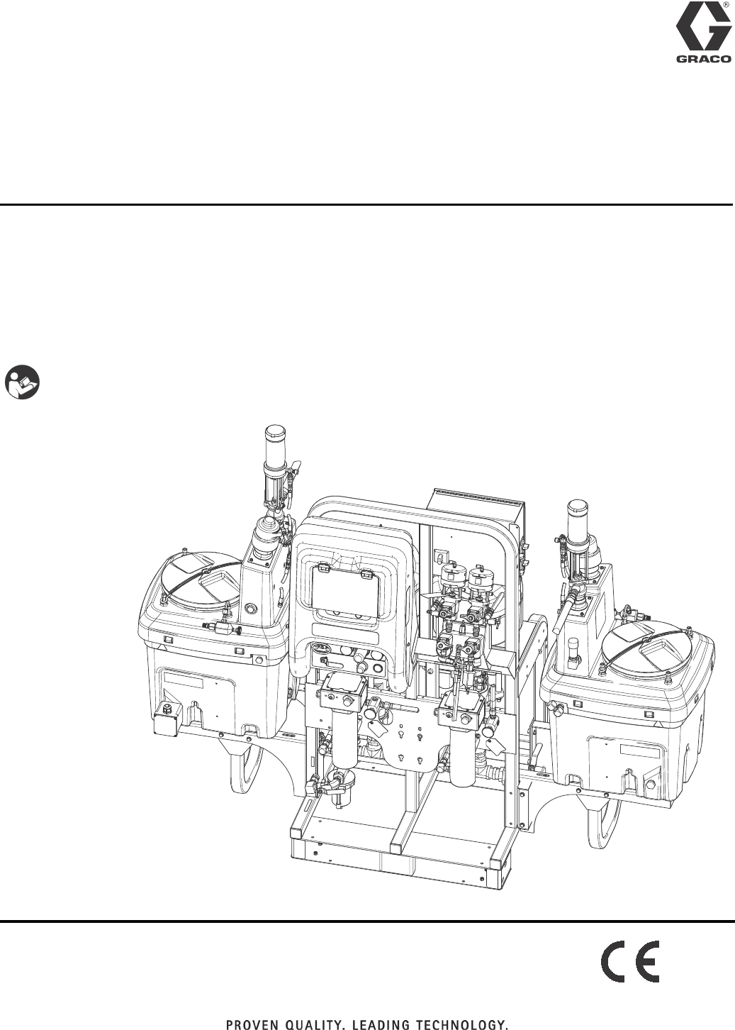
ti21272a
EN
2312359J
Contents
Related Manuals . . . . . . . . . . . . . . . . . . . . . . . . . . . 3
Warnings . . . . . . . . . . . . . . . . . . . . . . . . . . . . . . . . . 4
Models . . . . . . . . . . . . . . . . . . . . . . . . . . . . . . . . . . . 7
Overview . . . . . . . . . . . . . . . . . . . . . . . . . . . . . . . . . . 9
Usage . . . . . . . . . . . . . . . . . . . . . . . . . . . . . . . . . 9
Isocyanate Hazard . . . . . . . . . . . . . . . . . . . . . . . 9
Material Self-Ignition . . . . . . . . . . . . . . . . . . . . . . 9
Moisture Sensitivity of Isocyanates . . . . . . . . . . . 9
Components A and B . . . . . . . . . . . . . . . . . . . . 10
Changing Materials . . . . . . . . . . . . . . . . . . . . . . 10
Location . . . . . . . . . . . . . . . . . . . . . . . . . . . . . . . . . 11
Grounding . . . . . . . . . . . . . . . . . . . . . . . . . . . . . 11
Proper Lifting of Sprayer . . . . . . . . . . . . . . . . . . . 11
Initial System Setup . . . . . . . . . . . . . . . . . . . . . . . 12
Component Identification . . . . . . . . . . . . . . . . . . . 13
Typical Setup: 20 Gallon Hoppers with Recirculation
(Front View) . . . . . . . . . . . . . . . . . . . . . . . . 13
Typical Setup: 20 Gallon Hoppers with Recirculation
(Back View) . . . . . . . . . . . . . . . . . . . . . . . . . 14
Fluid Control Assembly . . . . . . . . . . . . . . . . . . . 15
Junction Box/Heater Controls . . . . . . . . . . . . . . 16
Air Controls . . . . . . . . . . . . . . . . . . . . . . . . . . . . 16
User Interface . . . . . . . . . . . . . . . . . . . . . . . . . . 17
Setup . . . . . . . . . . . . . . . . . . . . . . . . . . . . . . . . . . . . 19
Connect Power Cord . . . . . . . . . . . . . . . . . . . . . 19
Configure to Supply Power . . . . . . . . . . . . . . . . 20
Wire Sprayers with Explosion-Proof Heaters . . 21
Connect Air Supply . . . . . . . . . . . . . . . . . . . . . . 21
Connect Fluid Hose Assembly . . . . . . . . . . . . . 22
Adjust Packing Nuts . . . . . . . . . . . . . . . . . . . . . 22
Basic Operation . . . . . . . . . . . . . . . . . . . . . . . . . . . 23
Power On (Alternator Power Supplied Systems) 23
Power On (Wall Power Supplied Systems) . . . . 23
Adjust Ratio and Setup . . . . . . . . . . . . . . . . . . . 23
Final Setup . . . . . . . . . . . . . . . . . . . . . . . . . . . . 23
View Alarms . . . . . . . . . . . . . . . . . . . . . . . . . . . 23
Set System Settings (Optional) . . . . . . . . . . . . . 24
Set Maintenance Parameters (Optional) . . . . . . 25
Set Sprayer Limits (Optional) . . . . . . . . . . . . . . 26
Prime . . . . . . . . . . . . . . . . . . . . . . . . . . . . . . . . . . . . 27
Prime A and B Fluids . . . . . . . . . . . . . . . . . . . . 27
Prime Solvent Flush Pump . . . . . . . . . . . . . . . . 29
Recirculate . . . . . . . . . . . . . . . . . . . . . . . . . . . . . . . 30
Without Heat . . . . . . . . . . . . . . . . . . . . . . . . . . . 30
With Heat . . . . . . . . . . . . . . . . . . . . . . . . . . . . . 31
Heat Fluid . . . . . . . . . . . . . . . . . . . . . . . . . . . . . 31
Spray . . . . . . . . . . . . . . . . . . . . . . . . . . . . . . . . . . . . 32
Adjust B Machine Outlet Restriction . . . . . . . . . . 33
Pressure Relief Procedure . . . . . . . . . . . . . . . . . . 34
Flush Mixed Material . . . . . . . . . . . . . . . . . . . . . . . 36
Park Fluid Pump Rods . . . . . . . . . . . . . . . . . . . . . . 38
Shutdown Entire System . . . . . . . . . . . . . . . . . . . . 39
System Verification . . . . . . . . . . . . . . . . . . . . . . . . 40
Mix and Integration Tests . . . . . . . . . . . . . . . . . . 40
Pump and Metering Test . . . . . . . . . . . . . . . . . . 40
Batch Ratio Dispense Test . . . . . . . . . . . . . . . . 43
Down Stream Valve Leak Test . . . . . . . . . . . . . . 44
XM Setup and Troubleshooting Guide . . . . . . . . 45
Empty and Flush Entire System
(new sprayer or end of job) . . . . . . . . . . . . . . 46
Download Data from USB . . . . . . . . . . . . . . . . . . . 48
USB Logs . . . . . . . . . . . . . . . . . . . . . . . . . . . . . 48
Download Setup . . . . . . . . . . . . . . . . . . . . . . . . 48
Download Procedure . . . . . . . . . . . . . . . . . . . . . 48
Maintenance . . . . . . . . . . . . . . . . . . . . . . . . . . . . . . 50
Filters . . . . . . . . . . . . . . . . . . . . . . . . . . . . . . . . . 50
Seals . . . . . . . . . . . . . . . . . . . . . . . . . . . . . . . . . 50
Cleaning Procedure . . . . . . . . . . . . . . . . . . . . . . 50
Alarms . . . . . . . . . . . . . . . . . . . . . . . . . . . . . . . . . . . 51
View Alarms . . . . . . . . . . . . . . . . . . . . . . . . . . . . 51
Diagnose Alarms . . . . . . . . . . . . . . . . . . . . . . . . 51
Clear Alarms . . . . . . . . . . . . . . . . . . . . . . . . . . . 51
Alarm Codes and Troubleshooting . . . . . . . . . . 52
LED Diagnostic Information . . . . . . . . . . . . . . . . 58
Accessories and Kits . . . . . . . . . . . . . . . . . . . . . . . 59
Appendix A . . . . . . . . . . . . . . . . . . . . . . . . . . . . . . . 61
User Interface Display . . . . . . . . . . . . . . . . . . . . 61
Setup Mode Screens . . . . . . . . . . . . . . . . . . . . . 62
Operator Command Functions Screens . . . . . . 69
Auto Display Screens . . . . . . . . . . . . . . . . . . . . 75
Appendix B . . . . . . . . . . . . . . . . . . . . . . . . . . . . . . . 77
Metering Diagrams . . . . . . . . . . . . . . . . . . . . . . 77
Appendix C . . . . . . . . . . . . . . . . . . . . . . . . . . . . . . . 79
Power Cord Guidelines . . . . . . . . . . . . . . . . . . . 79
Dimensions . . . . . . . . . . . . . . . . . . . . . . . . . . . . . . . 80
System Dimensions without Hoppers . . . . . . . . 80
System Dimensions with Hoppers . . . . . . . . . . . 81
System Dimensions with Hoppers . . . . . . . . . . . 82
Pump Performance Charts . . . . . . . . . . . . . . . . . . 83
Technical Data . . . . . . . . . . . . . . . . . . . . . . . . . . . . 84
Graco Standard Warranty . . . . . . . . . . . . . . . . . . . 86
Graco Information . . . . . . . . . . . . . . . . . . . . . . . . . 86

Related Manuals
312359J 3
Related Manuals
Manuals are available at www.graco.com.
Component Manuals in U.S. English:
Manual Description
313289 XM Plural-Component Sprayers
Repair-Parts
313292 XM Plural-Component OEM Sprayers
Instructions-Parts
311762 Xtreme® Displacement Pumps
Instructions-Parts
311238 NXT™ Air Motor Instructions-Parts
312747 Double Wall Hopper Kit
Instructions-Parts
309524 Viscon® HP Heater Instructions-Parts
312145 XTR™ 5 and XTR™ 7 Spray Guns
Instructions-Parts
312769 Feed Pump and Agitator Kits
Instructions-Parts
312794 Merkur® Pump Assembly
Instructions-Parts
406699 7-Gallon Hopper Installation Kit
Instructions-Parts
406739 Desiccant Kit Instructions-Parts
406690 Caster Kit Instructions-Parts
406691 Hose Rack Kit Instructions-Parts
313258 Electric Heated Hose Power Supply Kit
Instructions-Parts
313259 Hopper or Hose Heat Circulation Kit
Instructions-Parts
312770 Lower Strainer and Valve Kit
Instructions-Parts
312749 XM Mix Manifold Kit
Instructions-Parts
313293 Alternator Conversion Kits
Instructions-Parts
313342 Dosing Valve Repair Kit
Instructions-Parts
313343 High Flow Severe Duty Shutoff Check
Valve Repair Kit Instructions-Parts
Warnings
4312359J
Warnings
The following warnings are for the setup, use, grounding, maintenance, and repair of this equipment. The exclama-
tion point symbol alerts you to a general warning and the hazard symbol refers to procedure-specific risk. Refer back
to these warnings. Additional, product-specific warnings may be found throughout the body of this manual where
applicable.
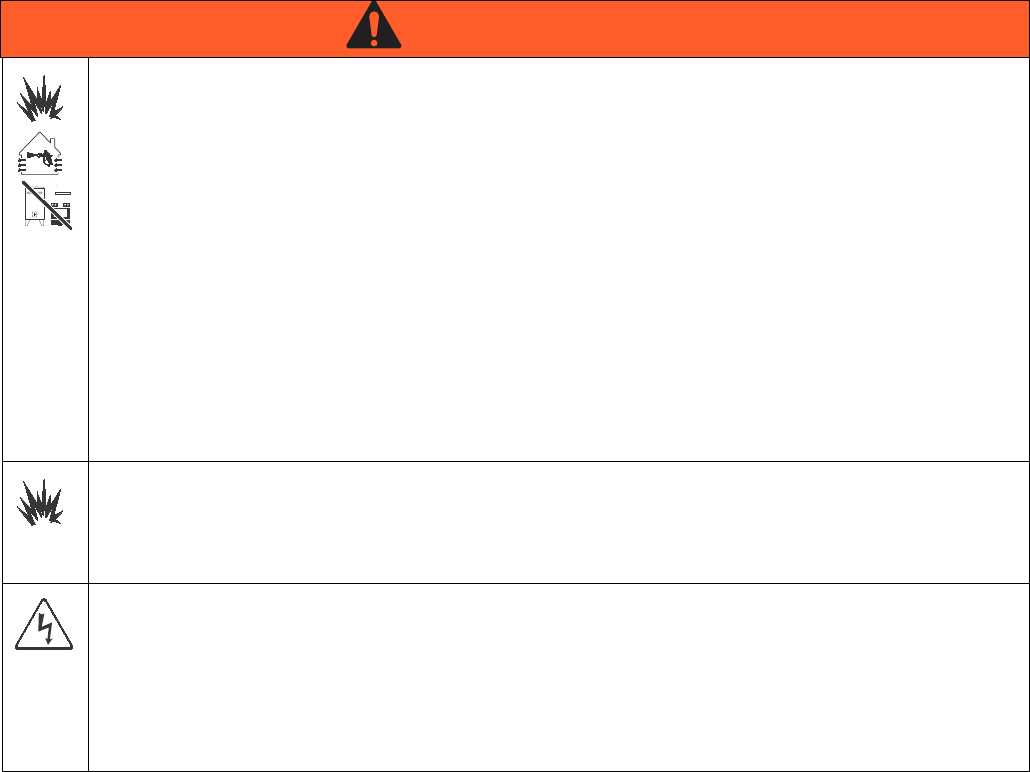
WARNINGWARNINGWARNING
WARNING
FIRE AND EXPLOSION HAZARD
Flammable fumes, such as solvent and paint fumes, in work area can ignite or explode. To help prevent
fire and explosion:
• Use equipment only in well ventilated area.
• Eliminate all ignition sources; such as pilot lights, cigarettes, portable electric lamps, and plastic drop
cloths (potential static arc).
• Keep work area free of debris, including solvent, rags and gasoline.
• Do not plug or unplug power cords, or turn power or light switches on or off when flammable fumes
are present.
• Ground all equipment in the work area. See Grounding instructions.
• Use only grounded hoses.
• Hold gun firmly to side of grounded pail when triggering into pail.
• If there is static sparking or you feel a shock, stop operation immediately. Do not use equipment
until you identify and correct the problem.
• Keep a working fire extinguisher in the work area.
• Do not connect USB device in explosive atmospheres.
SPECIAL CONDITIONS FOR SAFE USE
• To prevent the risk of electrostatic sparking, the equipment’s non-metallic parts must be cleaned with
only a damp cloth.
• Refer to the Viscon HP Heater manual for special conditions for safe use.
ELECTRIC SHOCK HAZARD
Improper grounding, setup, or usage of the system can cause electric shock.
• Turn off and disconnect power at main switch before disconnecting any cables and before servicing
equipment.
• Connect only to grounded power source.
• All electrical wiring must be done by a qualified electrician and comply with all local codes and
regulations.
Warnings
312359J 5
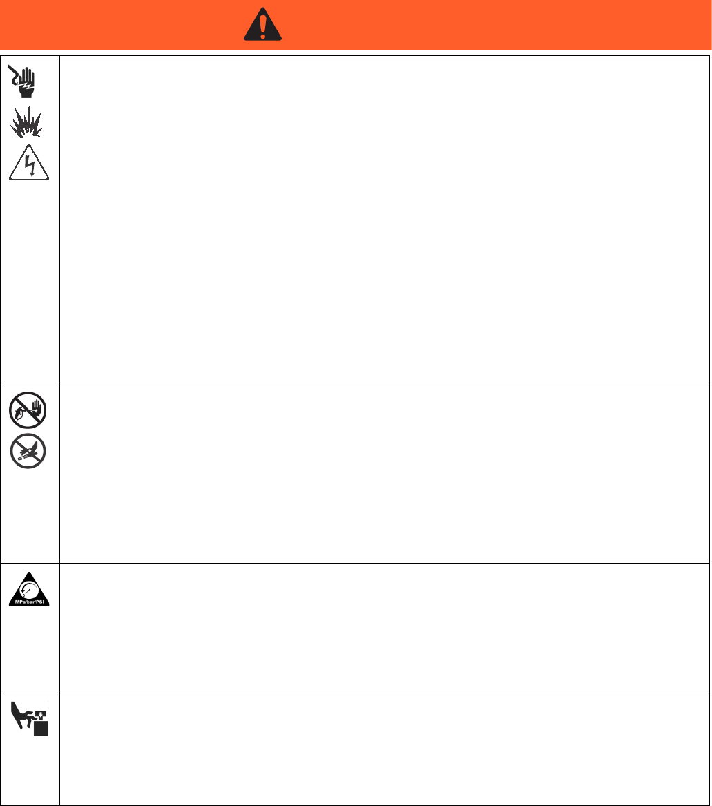
INTRINSIC SAFETY
Intrinsically safe equipment that is installed improperly or connected to non-intrinsically safe equipment
will create a hazardous condition and can cause fire, explosion, or electric shock. Follow local regula-
tions and the following safety requirements.
• Only models with model number XM_D_ _ or XM_E_ _, and packaged models with part numbers
ending in 00-13, 17-23, 27-29, 31, utilizing the air-driven alternator are approved for installation in a
Hazardous (explosive atmosphere) Location - see Approvals:, page 8. Only the models stated
above meet all local safety fire codes including NFPA 33, NEC 500 and 516, and OSHA 1910.107.
To help prevent fire and explosion:
• Do not install equipment approved only for a non-hazardous location in a hazardous location.
See model ID label for intrinsic safety rating of your model.
• Do not substitute system components as this may impair intrinsic safety.
• Equipment that comes in contact with the intrinsically safe terminals must be rated for Intrinsic
Safety. This includes DC voltage meters, ohmmeters, cables, and connections. Remove the unit
from the hazardous area when troubleshooting.
• Do not connect, download, or remove USB device unless unit is removed from the hazardous (explo-
sive atmosphere) location.
• If explosion-proof heaters are used, ensure wiring, wiring connections, switches, and electrical distri-
bution panel all meet flame-proof (explosion-proof) requirements.
SKIN INJECTION HAZARD
High-pressure fluid from gun, hose leaks, or ruptured components will pierce skin. This may look like just
a cut, but it is a serious injury that can result in amputation. Get immediate surgical treatment.
• Do not point gun at anyone or at any part of the body.
• Do not put your hand over the spray tip.
• Do not stop or deflect leaks with your hand, body, glove, or rag.
• Do not spray without tip guard and trigger guard installed.
• Engage trigger lock when not spraying.
•Follow Pressure Relief Procedure in this manual, when you stop spraying and before cleaning,
checking, or servicing equipment.
PRESSURIZED EQUIPMENT HAZARD
Fluid from the gun/dispense valve, leaks, or ruptured components can splash in the eyes or on skin and
cause serious injury.
•Follow Pressure Relief Procedure in this manual, when you stop spraying and before cleaning,
checking, or servicing equipment.
• Tighten all fluid connections before operating the equipment.
• Check hoses, tubes, and couplings daily. Replace worn or damaged parts immediately.
MOVING PARTS HAZARD
Moving parts can pinch or amputate fingers and other body parts.
• Keep clear of moving parts.
• Do not operate equipment with protective guards or covers removed.
• Pressurized equipment can start without warning. Before checking, moving, or servicing equipment,
follow the Pressure Relief Procedure in this manual. Disconnect power or air supply.
WARNING
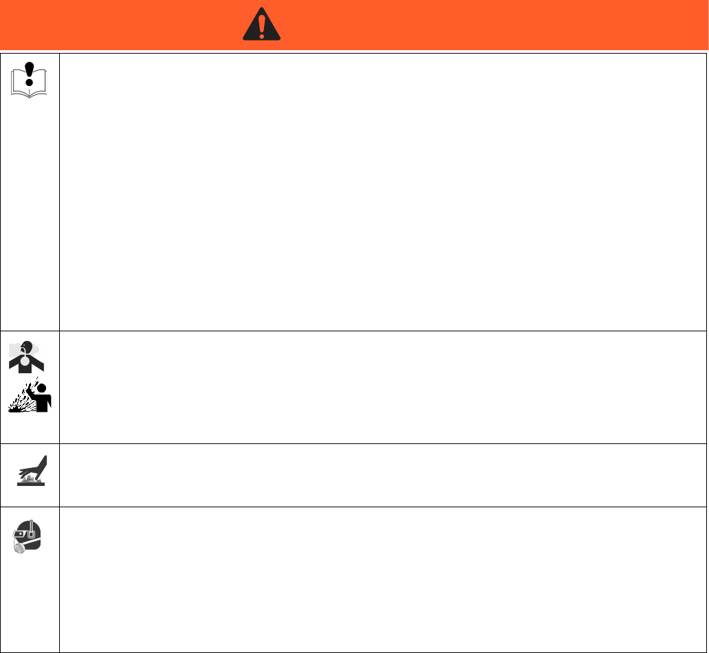
Warnings
6312359J
EQUIPMENT MISUSE HAZARD
Misuse can cause death or serious injury.
• Do not operate the unit when fatigued or under the influence of drugs or alcohol.
• Do not exceed the maximum working pressure or temperature rating of the lowest rated system
component. See Technical Data in all equipment manuals.
• Use fluids and solvents that are compatible with equipment wetted parts. See Technical Data in all
equipment manuals. Read fluid and solvent manufacturer’s warnings. For complete information
about your material, request MSDS forms from distributor or retailer.
• Check equipment daily. Repair or replace worn or damaged parts immediately with genuine manu-
facturer’s replacement parts only.
• Do not alter or modify equipment.
• Use equipment only for its intended purpose. Call your distributor for information.
• Route hoses and cables away from traffic areas, sharp edges, moving parts, and hot surfaces.
• Do not kink or over bend hoses or use hoses to pull equipment.
• Keep children and animals away from work area.
• Comply with all applicable safety regulations.
TOXIC FLUID OR FUMES HAZARD
Toxic fluids or fumes can cause serious injury or death if splashed in the eyes or on skin, inhaled, or
swallowed.
• Read MSDS’s to know the specific hazards of the fluids you are using.
• Store hazardous fluid in approved containers, and dispose of it according to applicable guidelines.
• Always wear impervious gloves when spraying or cleaning equipment.
BURN HAZARD
Equipment surfaces and fluid that’s heated can become very hot during operation. To avoid severe
burns, do not touch hot fluid or equipment. Wait until equipment/fluid has cooled completely.
PERSONAL PROTECTIVE EQUIPMENT
You must wear appropriate protective equipment when operating, servicing, or when in the operating
area of the equipment to help protect you from serious injury, including eye injury, inhalation of toxic
fumes, burns, and hearing loss. This equipment includes but is not limited to:
• Protective eyewear
• Clothing and respirator as recommended by the fluid and solvent manufacturer
•Gloves
• Hearing protection
WARNING
Models
312359J 7
Models
Check the identification plate (ID) for the 6-digit part number of the sprayer. Use the following matrix to define the
construction of the sprayer, based on the six digits. For example, Part XM1A00 represents an XM Plural-Component
sprayer (XM); 5200 psi pump set with pump filters (1); wall power supply, no heaters, no junction box, and is not
approved for hazardous areas (A); with no additional kits (00).
NOTE:
Some configurations in the following matrix cannot be built. Consult with distributor or Graco representative.
To order replacement parts, see Parts section the XM Plural-Component Sprayer Repair-Parts manual 313289. The
digits in the matrix do not correspond to the Ref. Nos. in the Parts drawings and lists.
Location Category Key:
NE Not for use in explosive atmospheres.
EH For use in explosive atmospheres and hazardous
locations.
XM sprayers are not approved for use in hazardous
locations unless the base model, all accessories, all
kits, and all wiring meet local, state, and national
codes.
XM 1 A 00
First and
Second
Digits Third Digit Fourth Digit
Fifth and
Sixth
Digits
System Choice
(See Table 1 for lower models) Kit Choice
Additional
Kit
Pump Set
(hose/gun)
Pump
Filters
Remote
Manifold
Control
Box
Fluid
Heaters
Junction
Box
Location
Category
Approvals
(see page 8
for approvals)
See Table
2 for
selections
XM
(plural com-
ponent
sprayer
mounted
on a frame)
15200 psi
✔
A
Wall Power
Supply NE
CE, FM,
FMc
25200 psi B
Wall Power
Supply
✔✔
NE CE, FM,
FMc
36300 psi
✔
C
Wall Power
Supply
✔NE CE, FM,
FMc
46300 psi D
IS/
Alternator EH
CE, FM,
FMc, Ex
55200 psi
✔✔
E
IS/
Alternator
✔
EH
CE, FM,
FMc, Ex
65200 psi ✔
76300 psi ✔✔
86300 psi ✔
Models
8312359J
Approvals:
See appropriate column on page 7.
NOTE:
See Accessories and Kits, page 59, for more information.
See Related Manuals, page 3, for kit manual numbers.
XM _ A_ _
XM _ B_ _
XM _ C_ _
XM _ D_ _
XM _ E_ _
Code
System Pressure
(MPa, bar)
Pump
Filters
A Lower
(see manual 311762)
B Lower
(see manual 311762)
1 or 5 5200 psi (35, 350) ✔L250C4 L220C4
2 or 6 5200 psi (35, 350) L250C3 L220C3
3 or 7 6300 psi (49, 490) ✔L180C4 L145C4
4 or 8 6300 psi (49, 490) L180C3 L145C3
Intrinsically safe for Class I, Div 1, Group D, T2
Class I, Division 1, Group D, T2
Ta = 0°C to 54°C
FM09ATEX0015X
II 2 G
Ex d ia px IIA T2 Tamb = 0ºC to 54ºC
See Special Conditions for Safe Use in Warnings, page 4.
Table 1: Lower Models and Corresponding Identification Codes
Table 2: Additional Kits - Identification Code/Part No. Index
20 Gal.
Hopper
Kit
Hopper
Heater
Kit 240V
Hopper
Fluid
Inlet Kit
Hopper
Universal
Mount
Kit
Twistork
Agitator
Kit
T2 Pump
Feed Kit
(on
hopper)
5:1 Pump
Feed Kit
(on
hopper)
7 Gal.
Hopper
(Green)
and
Bracket
Kit
7 Gal.
Hopper
(Blue)
and
Bracket
Kit
Drum
Feed Kit
(Dual T2
and
Agitator)
Drum
Feed Kit
(Dual 5:1
and
Agitator)
Heated
Hopper/
Hose
Circulation
Kit
00
11 1111 1
13 11111
14 11111 1
15 11 11 1 1
16 11 11 11
17 1111 1 1
19 11111 1
21 2222
23 2222
24 22222
25 22 22 2
26 22 22 2
27 2222 1
29 2222 1
30 2
31 2
32 11
Overview
312359J 9
Overview
Usage
XM plural-component sprayers can mix and spray most
two-component epoxy and urethane protective coatings.
When using quick-setting materials (less than 10 minute
pot life) a remote mix manifold must be used.
XM plural-component sprayers are operated via the user
interface, air controls, and fluid controls.
Isocyanate Hazard
Material Self-Ignition
Moisture Sensitivity of
Isocyanates
Isocyanates (ISO) are catalysts used in two component
urethane coatings. ISO will react with moisture (such as
humidity) to form small, hard, abrasive crystals, which
become suspended in the fluid. Eventually a film will
form on the surface and the ISO will begin to gel,
increasing in viscosity. If used, this partially cured ISO
will reduce performance and the life of all wetted parts.
NOTE:
The amount of film formation and rate of crystallization
varies depending on the blend of ISO, the humidity, and
the temperature.
To prevent exposing ISO to moisture:
• Always use a sealed container with a desiccant
dryer in the vent, or a nitrogen atmosphere. Never
store ISO in an open container.
• Use moisture-proof hoses specifically designed for
ISO, such as those supplied with your system.
• Never use reclaimed solvents, which may contain
moisture. Always keep solvent containers closed
when not in use.
• Never use solvent on one side if it has been contam-
inated from the other side.
• Always park pumps when you shutdown.
• Always lubricate threaded parts with Part 217374
ISO pump oil or grease when reassembling.
XM sprayers are not approved for use in hazardous
locations unless the base model, all accessories, all
kits, and all wiring meet local, state, and national
codes. See Models, page 7, to determine the appro-
priate location for your particular sprayer model.
Spraying materials containing isocyanates creates
potentially harmful mists, vapors, and atomized partic-
ulates.
Read material manufacturer’s warnings and material
MSDS to know specific hazards and precautions
related to isocyanates.
Prevent inhalation of isocyanate mists, vapors, and
atomized particulates by providing sufficient ventila-
tion in the work area. If sufficient ventilation is not
available, a supplied-air respirator is required for
everyone in the work area.
To prevent contact with isocyanates, appropriate per-
sonal protective equipment, including chemically
impermeable gloves, boots, aprons, and goggles, is
also required for everyone in the work area.
Some materials may become self-igniting if applied
too thick. Read material manufacturer’s warnings and
material MSDS.

Overview
10 312359J
Components A and B
IMPORTANT!
Material suppliers can vary in how they refer to plural
component materials.
Be aware that in this manual:
Component A refers to resin or major volume.
Component B refers to the hardener or minor volume.
NOTE:
This equipment doses the B component into the A com-
ponent flow. An integration hose must always be used
after the mix manifold and before the static mixer.
NOTE:
Follow these recommendations for setup:
• use at least a 3/8 in. (10 mm) x 25 ft. (7 m) hose as
the integration hose.
• install a 24-element static mix tube after the integra-
tion hose.
Keep Components A and B Separate
Changing Materials
• When changing materials, flush the equipment mul-
tiple times to ensure it is thoroughly clean.
• Always clean the fluid inlet strainers and outlet filter
after flushing, Flush Mixed Material, page 36.
• Check with your material manufacturer for chemical
compatibility.
• Epoxies often have amines on the B (hardener)
side. Polyureas often have amines on the A (resin)
side.
NOTE:
If the amine will switch between the two sides, see
Flush Mixed Material, page 36.
NOTICE
To prevent cross-contamination of the equipment’s wet-
ted parts, never interchange component A (resin) and
component B (hardener) parts.
Location
312359J 11
Location
Grounding
Connect the XM sprayer ground wire clamp (FG) to a
true earth ground. If wall power is used to power con-
trols or heaters, ground electrical connection properly
according to local codes.
Proper Lifting of Sprayer
Lift Using a Forklift
Power must be off. Sprayer can be raised and moved
using a forklift. Carefully lift the sprayer; make sure it
balances evenly.
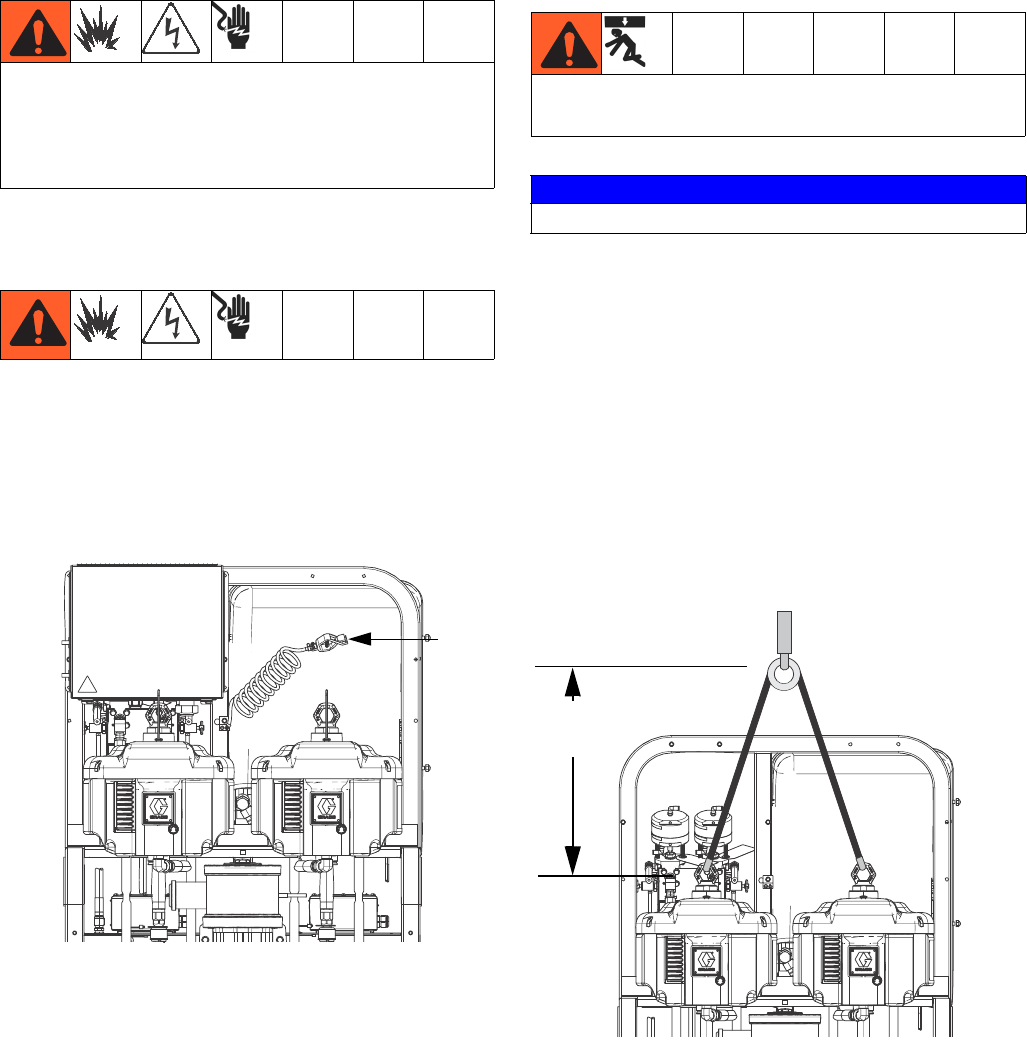
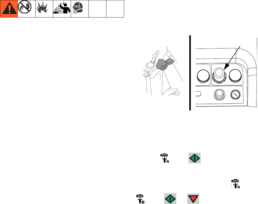
Lift Using a Hoist
Sprayer can also be lifted and moved using a hoist. Con-
nect a bridle swing, hooking an end to each of the air
motor lift rings. Hook the center ring to a hoist. See the
following figure. Carefully lift the sprayer; make sure it
balances evenly.
XM sprayers are not approved for use in hazardous
locations unless the base model, all accessories, all
kits, and all wiring meet local, state, and national
codes. See ModelsModels, page 7, to determine the
appropriate location for your particular sprayer model.
FG
ti21273a
Follow instructions to avoid serious injury or damage
to equipment. Never lift with the hopper(s) filled.
NOTICE
Drain all fluid prior to lifting sprayer.
2.0 ft. (0.61 m)
minimum
ti21274a
Initial System Setup
12 312359J
Initial System Setup
Complete the following steps in the order they are listed,
as they apply to your specific system, for initial system
setup.
1. Check your shipment for accuracy. Ensure you have
received everything you ordered. See Component
Identification, page 13, to familiarize yourself with
typical system components.
2. Mount caster kit, if ordered. See manual 406690 for
instructions.
3. Mount hopper brackets, if ordered. See manual
312747 for instructions.
4. Loosely mount hoppers, if ordered, on brackets. See
manual 312747 for instructions.
5. Connect bottom hopper outlet if using a gravity feed
pump. See manual 312747 for instructions.
6. Tighten hopper mounting bolts. See manual 312747
for instructions.
7. Mount and connect agitator(s) and feed pump(s), if
ordered. See manual 312769 for instructions.
8. Mount and connect hopper immersion heater kit, if
ordered. See manual 312747 for instructions.
9. Connect recirculation hose, restrictor valve (includ-
ing knob and nipple), and recirculation tube. Place
in hopper or drum. See manual 312747 for instruc-
tions.
10. Replace USB label (front of control panel) with cor-
rect language version, if needed.
11. Replace Alarms Codes label (under fluid control
valves) with correct language version, if needed.
12. Install hopper/hose heated circulation kit, if ordered.
See manual 313259 for instructions.
13. For non-hazardous location sprayers, connect
power cord (not supplied). See Connect Power
Cord, page 19, for instructions.
14. For non-hazardous location sprayers, connect junc-
tion box wiring for immersion or recirculation heat-
ers. See manual 312747 for immersion heater
instructions. See manual 309524 for recirculation
heater instructions.
15. For hazardous location sprayers, connect explo-
sion-proof heaters. See Wire Sprayers with Explo-
sion-Proof Heaters, page 21, and manual 309524
for instructions and recommendations.
16. Connect air supply line. See Connect Air Supply,
page 21, for instructions and recommendations.
17. Connect fluid hose assembly, including whip hose
and gun. See Connect Fluid Hose Assembly,
page 22, for instructions. Also connect remote mix
manifold, if ordered. See manual 312749 for instruc-
tions.
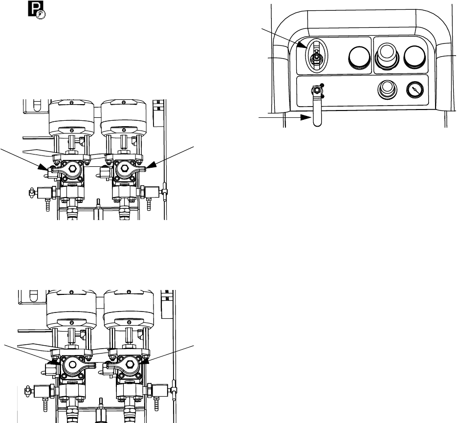
Component Identification
312359J 13
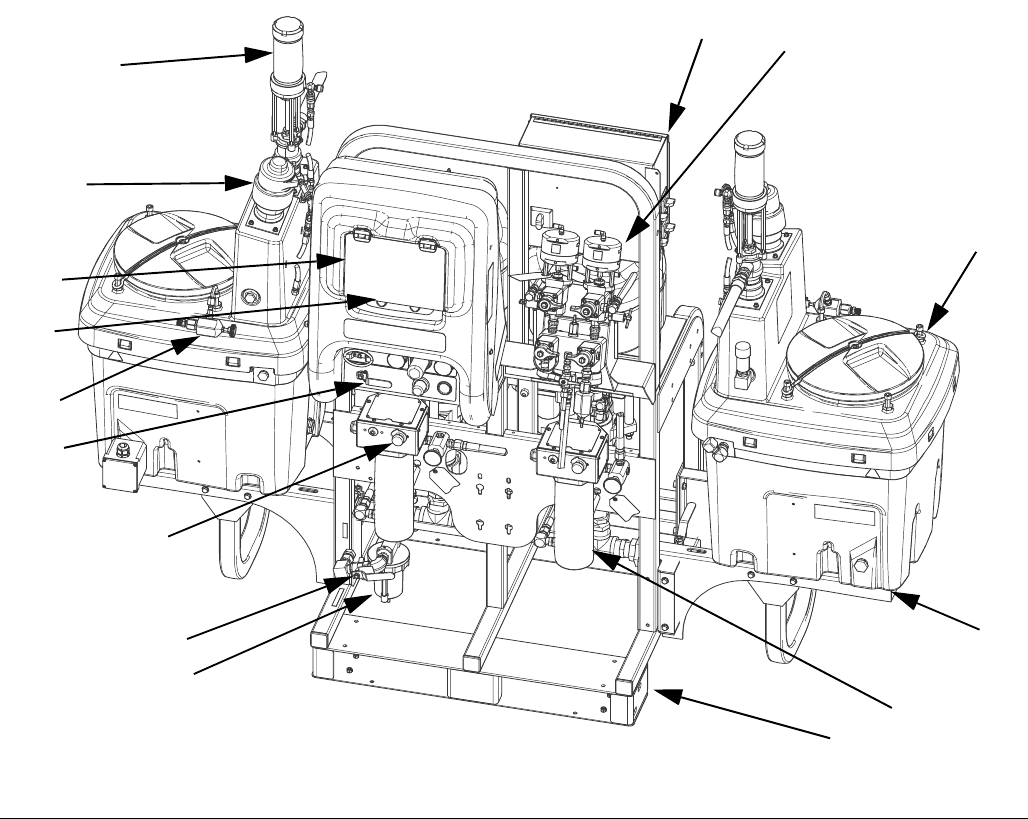
Component Identification
Typical Setup: 20 Gallon Hoppers with Recirculation (Front View)
AFrame
B Fluid Control Assembly (see Fluid Control Assembly,
page 15)
C 20 Gallon Hopper Assembly (see manual 312747)
D 20 Gallon Hopper Bracket (see manual 312747)
E Main Air Valve
F GCA Control Display (see User Interface Display, page
18)
G Pump Control On and Off Buttons
H Air Filter
J Air Controls
K Viscon HP Fluid Heater
L Junction Box/Heater Controls (see Junction Box/Heater
Controls, page 16)
M Inline Fluid Heater Control
N Air Powered Agitator
P Pressure Feed Pump
R Recirculation Control Valve
FIG. 1: Typical Setup: 20 Gallon Hoppers with Recirculation (Front View)
A
K
D
C
B
L
E
F
G
J
H
M
P
N
R
ti21272a
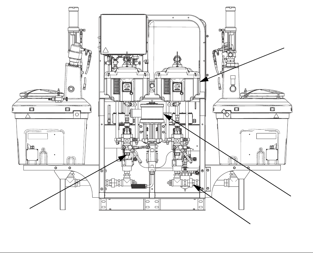
Component Identification
14 312359J
Typical Setup: 20 Gallon Hoppers with Recirculation (Back View)
S Air Motor
T High Pressure Fluid Pump
U Solvent Flush Pump (Merkur® Pump)
V Fluid Inlet Assembly
FIG. 2: Typical Setup: 20 Gallon Hoppers with Recirculation (Back View)
V
U
S
T
Component Identification
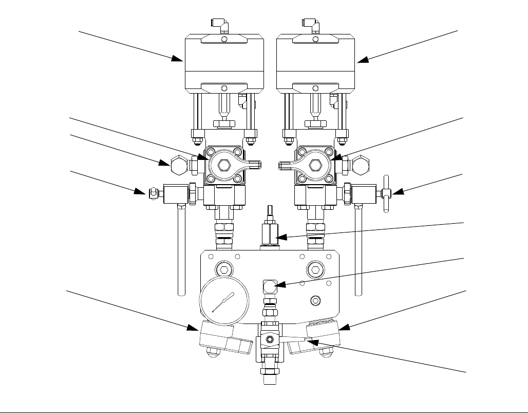
312359J 15
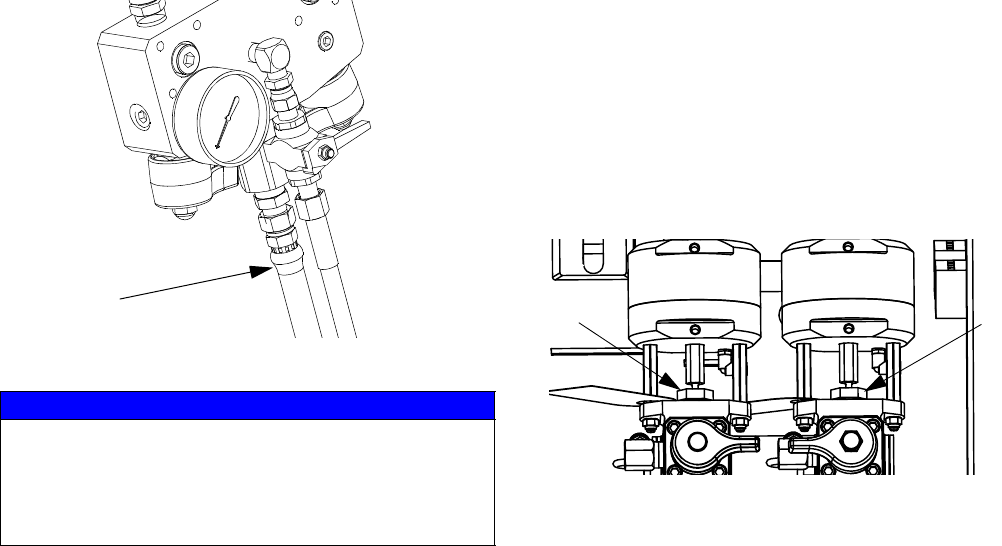
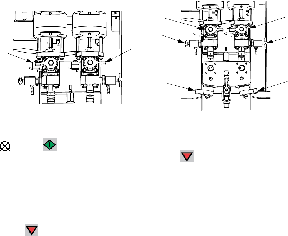
Fluid Control Assembly
AA Dosing Valve A
AB Dosing Valve B
AC Recirculation Valve A
AD Recirculation Valve B
AE Sampling Valve A
AF Sampling Valve B
AG Restriction Valve
AH Mix Manifold Shutoff / Check Valve A
AJ Mix Manifold Shutoff / Check Valve B
AK Solvent Shutoff Valve
AL Pressure Sensor
AM Solvent Check Valve
FIG. 3: Fluid Control Assembly
AB
AD
AF
AG
AJ
AK
AA
AC
AE
AH
AL
r_XM1A00_312359_313289_18A
AM
Component Identification
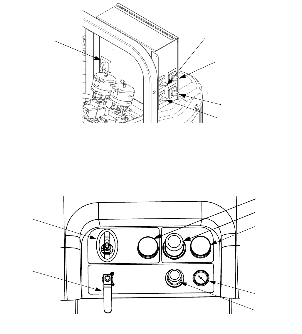
16 312359J
Junction Box/Heater Controls
BA Main Power Disconnect Switch
BB Fluid Heater A Control
BC Fluid Heater B Control
BD Hopper Heater A Control
BE Hopper Heater B Control
Air Controls
CA Main Pump and Air On/Off Control
CB Solvent Pump Air On/Off Control
CC Inlet Air Pressure Gauge
CD Main Pump Air Regulator
CE Main Pump Air Regulator Gauge
CF Solvent Pump Air Gauge
CG Solvent Pump Air Regulator
FIG. 4: Junction Box/Heater Controls
BB
BC
BD
BE
BA
FIG. 5: Air Controls
CA
CB
CC
CD
CE
CG
CF
r_XM1A00_312359_313289_14A
Component Identification
312359J 17
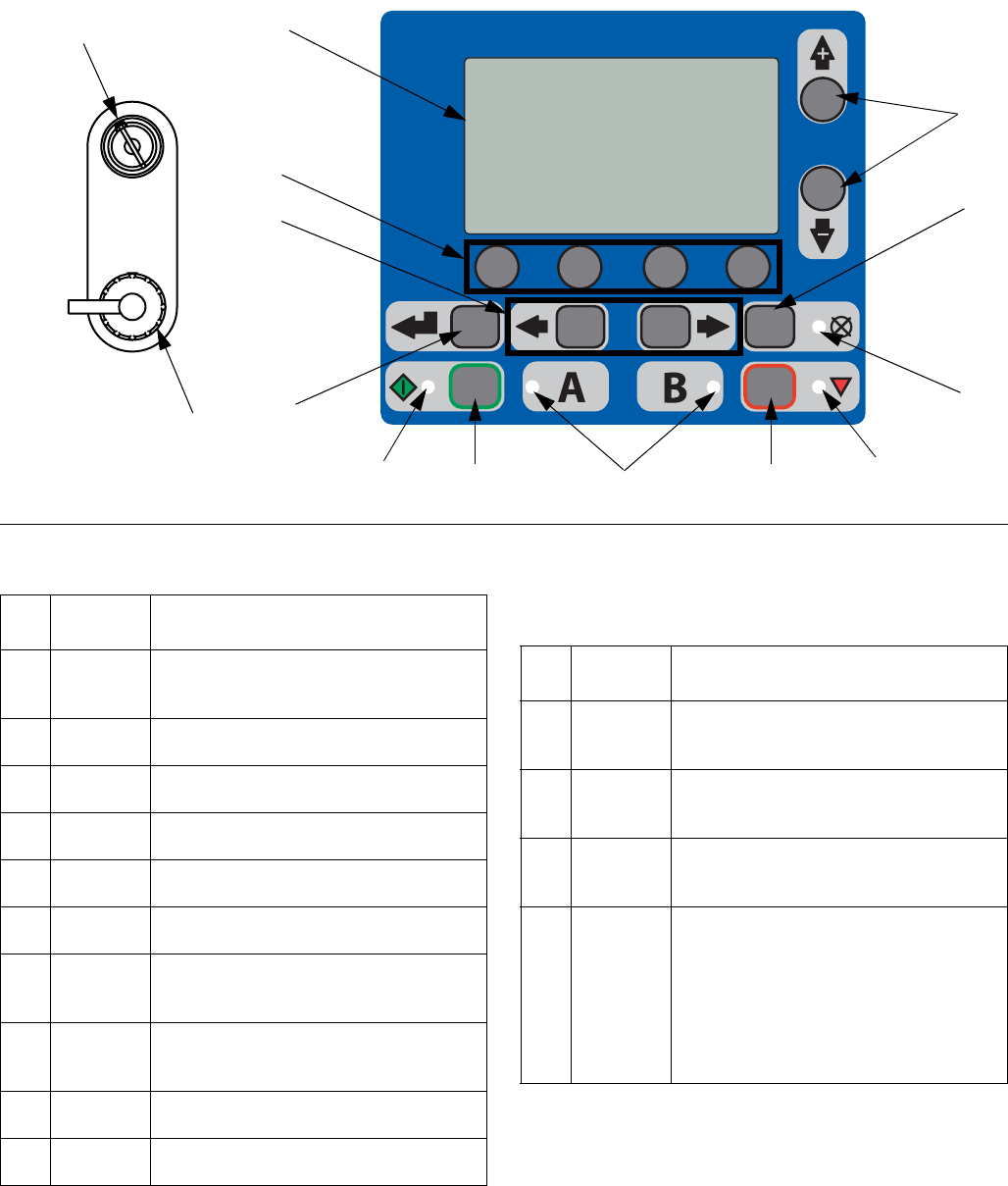
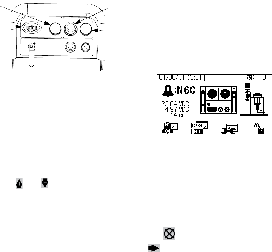
User Interface
Buttons LEDs
There are four types of LEDs on the display.
FIG. 6: User Interface
DA
DB
DD
DE
DF
DG
DH
DK
DP
DN
DM DC
ti13365a
DR
DJ
Call
out Button Function
DA Display
Screen
Use to view Ratio, Mode Selection, Error
Conditions, Totalizers, System Informa-
tion.
DB Start Initiates Active Run Mode function cur-
rently selected in Run Screen.
DC Stop Terminates Active Run Mode function
currently selected.
DD Enter Press to open drop-down fields, selection
options, and save values.
DE Alarm
Reset
Resets alarms and advisories.
DF Left/Right Move between screens in run or setup
modes.
DG Function Activates mode or action represented by
the icon above each of the four buttons in
the LCD.
DH Up/Down Move between selection boxes,
drop-down fields, and selectable values
within Setup screens.
DJ Setup Key
Lock
Change ratio or enter Setup mode.
DR USB Port Connection for data download. Use only
in non-hazardous locations.
Call
out LED Function
DK Blue Dosing valve active
• on - dosing valve is active
• off - dosing valve is not active
DM Green Spray mode active
• spray mode is on (active)
• spray mode is off (inactive)
DN Red Alarm
• on - alarm is present
• off - no alarm
DP Yellow Warning
• on - is active.
• off - no warning indicated. Ratio
and setup fields are not change-
able.
• flashing - key is present and
turned. Ratio and setup fields
are changeable.
Component Identification
18 312359J
User Interface Display
NOTE:
For details regarding the user interface display see User
Interface Display, page 61.
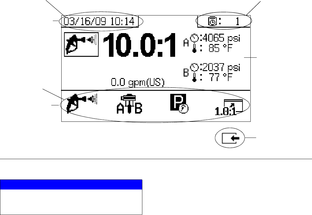
Main Display Screen Components
The following figure calls out the navigational, status, and general informational components of each display screen.
FIG. 7: Main Display Screen Components (shown with all display features enabled)
NOTICE
To prevent damage to soft key buttons, do not press
the buttons with sharp objects such as pens, plastic
cards, or fingernails.
Current Date and Time
Navigate to screens
within same group
Go back one screen
Current Status Bar
Navigational Bar
Function Display
Remaining Potlife Time
Setup
312359J 19
Setup
Connect Power Cord
(For sprayers with heater junction boxes.
Non-hazardous location sprayers only.)
Graco does not supply heater junction box power cords.
Use the following chart to determine which power cord
your specific model requires.
NOTE:
Sprayers without heaters for non-hazardous locations
include a U.S. style NEMA 5-15 power cord and an
IEC-320 power cord. (European and Australian adapters
are also included.) These power cords are rated for
90-240 Vac, 47-63 Hz. See the XM Plural-Component
Sprayers Repair-Parts manual or the XM Plural-Compo-
nent OEM Sprayers Instructions-Parts manual for part
numbers.
NOTE:
Disregard terminal numbers on disconnect switch
blocks. Wire to positions shown.
1. Open junction box cover.
2. Connect electrical cord as follows.
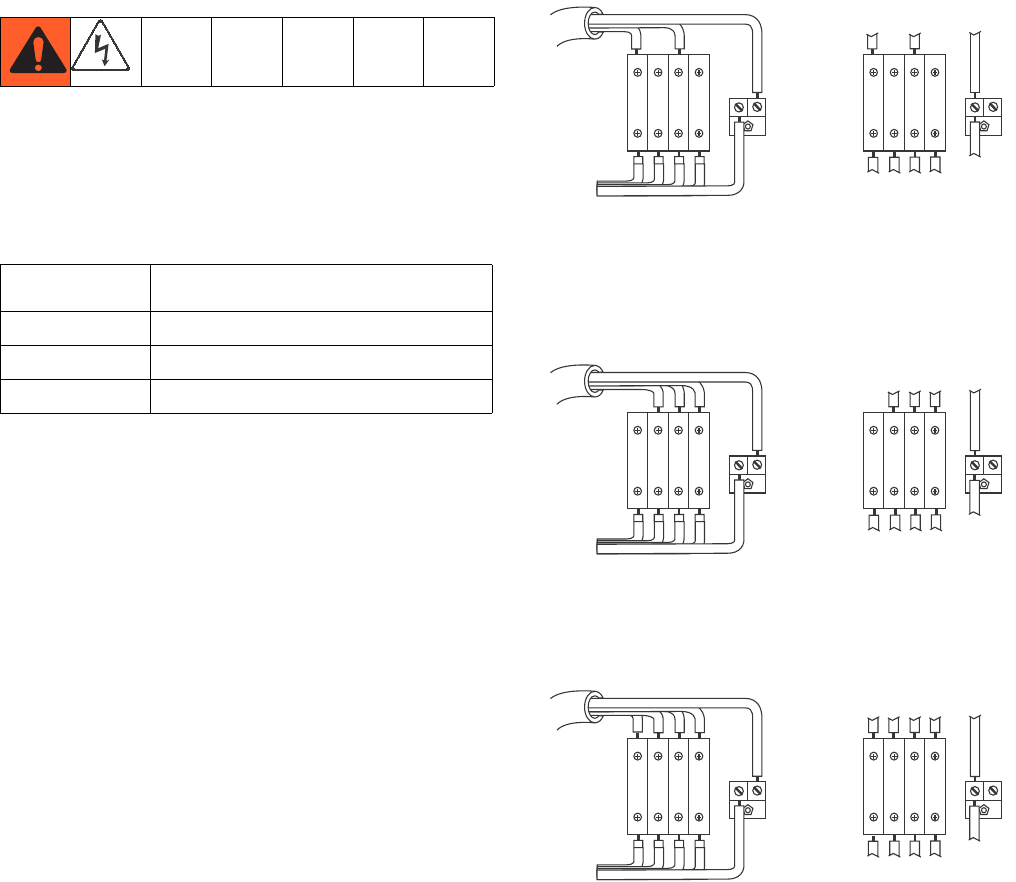
230V, 1 Phase: Use a screwdriver to connect two power
leads to the top terminals N and L2 positions. Connect
green to ground (GND).
230V, 3 Phase Delta: Use a screwdriver to connect
three power leads to top terminals L1, L2, and L3. Con-
nect green to ground (GND).
380V, 3 Phase WYE: Use a screwdriver to connect three
power leads to the top terminals L1, L2, and L3. Connect
neutral to N. Connect green to ground (GND).
Power Cord Requirements
Voltage Cord Specification AWG (mm2)
240V, 1 PH 4 (21.2) 2 wire + ground
240V, 3 PH 6 (13.3) 3 wire + ground
380V, 3 PH 6 (13.3) 4 wire + ground
7L4
1L1
L1 L2 PE
GRND
L1 L2 L3N 123N
NL1 L2 L3
G
ti8611a
1L1
L1 L2 L3 PE
GRND
L1 L2 L3N 123N
NL1 L2 L3
G
ti8612a
7L4
1L1
N
L1N L2 L3 PE
GRND
L1 L2 L3 123N
NL1 L2 L3
G
ti8613a
Setup
20 312359J
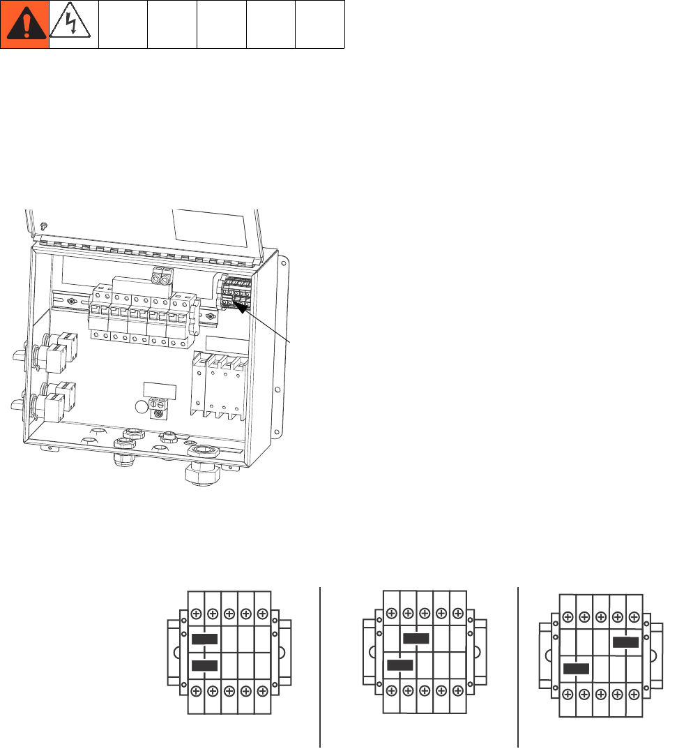
Configure to Supply Power
(Non-hazardous location sprayers only.)
NOTE:
Disregard terminal numbers on disconnect switch
blocks. Wire to positions shown.
1. Locate power jumpers.
2. Use a flat-blade screwdriver to move red jumpers
from storage positions to positions for your power as
shown below. Push jumpers firmly into new position.
NOTE:
For 230V, 1 Phase and 230V, 3 Phase Installations,
change jumper positions as shown below. Machine is
shipped with jumpers in the fail-safe 380 3Ø position.
3. Close junction box cover.
ti18664a
Power
Jumpers
L3 L2 L1 N
230V 1ø
L3 L2 L1 N
230V 3ø Delta
L3 L2 L1 N
380V 3ø WYE
TB2
Terminal Blocks
Position red jumpers
as shown
(as shipped)
Setup
312359J 21
Wire Sprayers with
Explosion-Proof Heaters
(Hazardous location sprayers only)
Improperly installed or connected equipment will create
a hazardous condition and cause fire, explosion, or elec-
tric shock. Follow local regulations.
When explosion-proof heaters are used, ensure wiring,
wiring connections, switches, and electrical distribution
panel all meet flame-proof (explosion-proof) require-
ments.
Refer to Viscon HP heater manual 309524 for electrical
connection instructions and guidelines in hazardous
locations.
Connect Air Supply
Connect air supply line to 3/4 npt(f) air filter inlet.
NOTE:
Use a 3/4 in. (19.1 mm) ID minimum air hose.
NOTE:
Air supply requirement: 150 psi (1.0 MPa, 10.3 bar)
maximum; 50 psi (0.35 MPa, 3.5 bar) minimum (while
running).
Flow volume required: 70 scfm (1.96 m3/min) minimum;
250 scfm (7.0 m3/min) maximum. Available fluid pres-
sure and flow rate are directly related to available air vol-
ume. See Pump Performance Charts, page 83.
General flow volume guidelines:
• 70 scfm (1.96 m3/min) per gpm (lpm) while
spraying
• 10 scfm (0.28 m3/min) added per agitator
• 10 scfm (0.28 m3/min) added per drum feed
pump
NOTE:
If your sprayer is for use in hazardous areas, the control
box is powered by an air-driven alternator.
NOTE:
Dosing valves are operated by air. The sprayer will not
operate correctly if the inlet air gauge drops below 50
psi (0.35 MPa, 3.5 bar) while spraying.
If your sprayer is rated for hazardous areas, and you
have explosion-proof heaters, you must have a quali-
fied electrician connect heater wiring. Ensure wiring
and installation comply with local electrical codes for
hazardous areas.
E
Setup
22 312359J
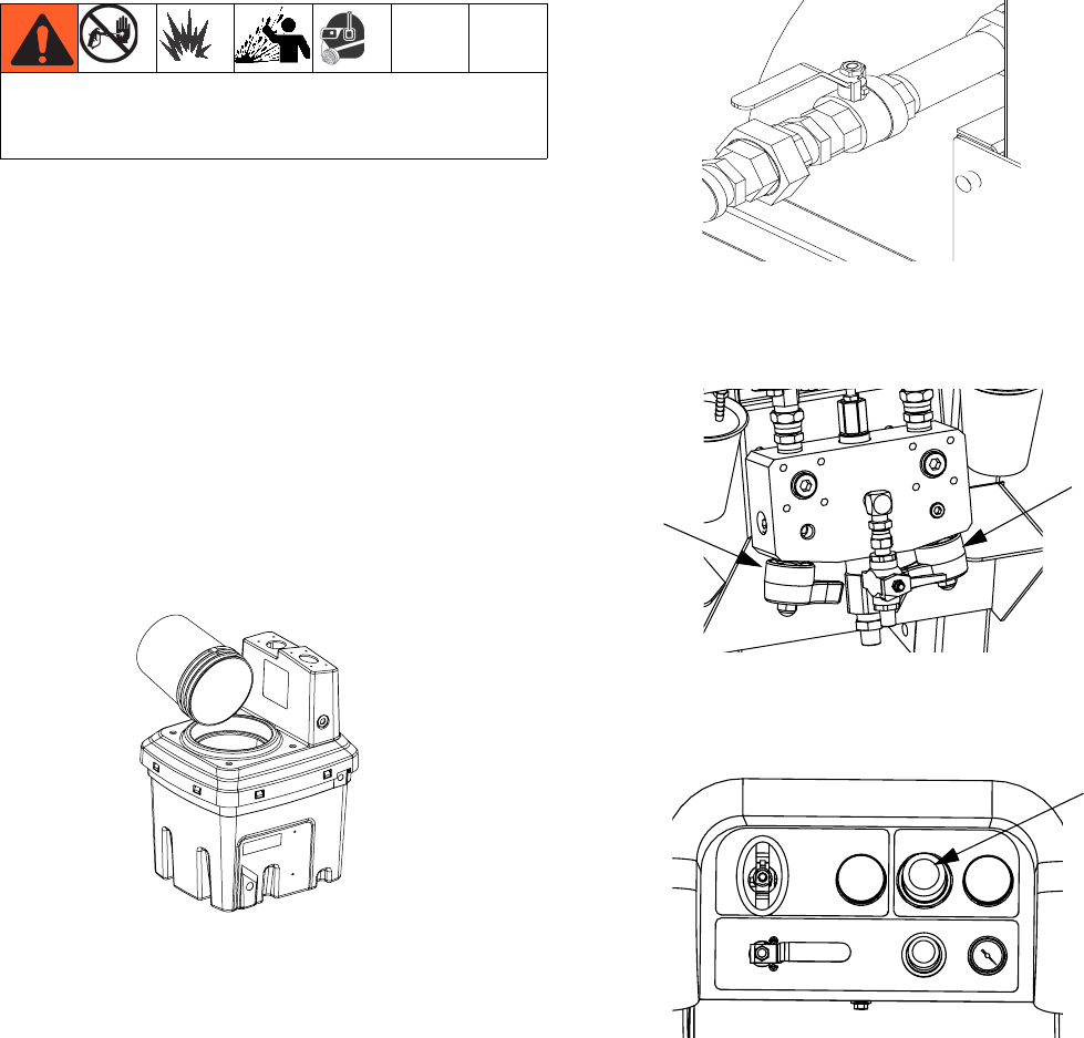
Connect Fluid Hose Assembly
1. Connect fluid hose to fluid manifold outlet. Do not
install gun spray tip yet.
2. Tighten all fittings.
Adjust Packing Nuts
1. Fill A and B pump packing nuts with throat seal liq-
uid (TSL™) and torque to 50 ft-lbs (67.5 N•m). Fol-
low instructions in Xtreme Lowers manual 311762.
NOTE:
After the first day of use re-torque packing nuts.
2. Fill metering valves A and B packing nuts with throat
seal liquid (TSL) and tighten 1/4 turn after nut con-
tacts packings; about 145-155 in-lbs (16-18 N•m).
NOTE:
For pump and meter valves, check packing nut tightness
after first hour of operation and again after 24 hours.
Then check as needed, or when TSL discolors or seeps
over packing nut. Also check tightness whenever
sprayer is transported. Tighten packing nuts only when
all fluid pressure is relieved.
NOTICE
Do not assemble static mixer directly to the fluid man-
ifold. Install static mixer after first 25 ft. (7.5 m) of inte-
grator hose to ensure material doses are completely
integrated. Spraying poorly integrated material could
require rework of parts sprayed.
Fluid
Integrator
Hose
r_XM1A00_312359_313289_20A
TSL TSL
Basic Operation
312359J 23
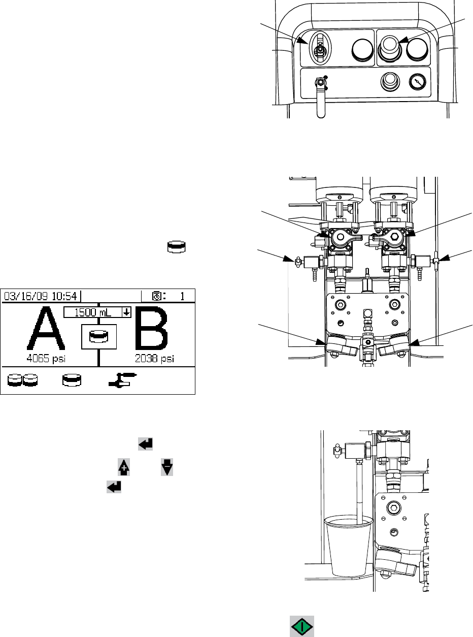
Basic Operation
Power On (Alternator Power
Supplied Systems)
1. Set main pump air regulator (CD) to minimum set-
ting.
2. Open main air valve (E) and main pump and air
valve (CA) to start air-powered alternator.
Main air pressure is displayed on gauge (CC). Fluid
Control screen will display after five seconds.
Power On (Wall Power Supplied
Systems)
Turn on main power disconnect. Fluid Control screen
will display after five seconds.
Adjust Ratio and Setup
1. Turn key to right (setup position). Yellow LED will
flash and the Home Setup screen will display.
2. Press and to change ratio.
3. When desired ratio is displayed, turn key to left. Yel-
low LED will turn off.
4. Change optional setup selections to desired param-
eters, as described in Set System Settings
(Optional), page 24.
Final Setup
Perform the following steps if shutting down during
setup.
1. Relieve system pressure. See Pressure Relief Pro-
cedure, page 34.
2. Flush and prime system. See Prime (page 27),
Flush Mixed Material (page 36) and Park Fluid
Pump Rods (page 38).
3. Check ratio accuracy. Run Pump and Metering
Test (page 40) and Batch Ratio Dispense Test
(page 43) to check ratio accuracy.
View Alarms
When an alarm occurs the alarm information screen
automatically displays. It shows the current alarm code
along with a bell icon. It also shows the alarm location
with top and side views of the sprayer
There are two levels of error codes: alarms and adviso-
ries. A bell icon indicates an alarm. A solid bell icon with
an exclamation point and three audible alerts indicate a
alarm. And an outlined hollow bell icon and a single
audible alert indicate an advisory.
Diagnose Alarms
See Alarm Codes and Troubleshooting, page 52, for
causes and solutions to each alarm code.
Clear Alarms
Press to clear alarms and advisories. Press
to return the run (fluid control) screen.
For more information on alarms and alarm codes, see
Alarms, page 51.
CD
CE
CC
CA
Basic Operation
24 312359J
Set System Settings (Optional)
NOTE:
For details regarding the user interface display screens
see User Interface Display, page 61.
To set user interface parameters and USB parameters,
press from the Home Setup screen.
Set User Interface Parameters
Press from the potlife/hose length screen to
move to the user interface parameters screen.
The following user interface parameters are configu-
rable:
• date format
• date (factory set)
• time (factory set)
• units of measurement for:
• fluid flow rate
•pressure
• temperature
• hose length
To change the date format, press to select the field.
Press to open the drop down field. Press
and to select the preferred format. Press
again to save that date format. Follow this procedure to
change the units of measurement formats as well.
To change the date and time, press to select the
field. Press to make the field selectable. Press
and to scroll through each digit. Press
and to move to the next digit in the field.
Press to save the change.
Set USB Parameters
Press from the user interface parameters
screen to move to the USB parameters screen.
To set the sprayer number, configure the number of
hours downloaded to external USB flash drive, and how
often the data will record: press and to move
through each field. Press to make a field select-
able. Press and to scroll through each digit.
Press and to move to the next digit in
each field. Press to save the change.
Basic Operation
312359J 25
Set Maintenance Parameters
(Optional)
NOTE:
Prior to configuring system settings, see Enable Setup
Screens, page 66, to ensure screens shown in this sec-
tion are viewable and configurable. If they are not, follow
instructions in Enable Setup Screens to enable them.
NOTE:
For details regarding the user interface display screens
see User Interface Display, page 61.
To set maintenance parameters for pumps and valves,
including maintenance schedules, press from
the Home Setup screen.
Use the first screen to set maintenance setpoint
amounts for pumps and dosing valves. Use the second
screen to set the maintenance schedule for changing
the incoming air filter.
Set Maintenance Setpoints
To set maintenance setpoint values, press and
to move through each field, and press to
make a field selectable. Press to scroll through
each setpoint digit. Press and to scroll
through the optional values. Continue this process until
the desired setpoint is reached. Press to save
that setpoint.
Set Maintenance Schedule
To set the number of days between changing the incom-
ing air filter that will result in a reminder advisory, press
to move to the Maintenance Setup 2 screen.
Press to make the field selectable. Press
to scroll through each digit, and press and to
scroll through the optional values. Press to save
the number of days value.
Basic Operation
26 312359J
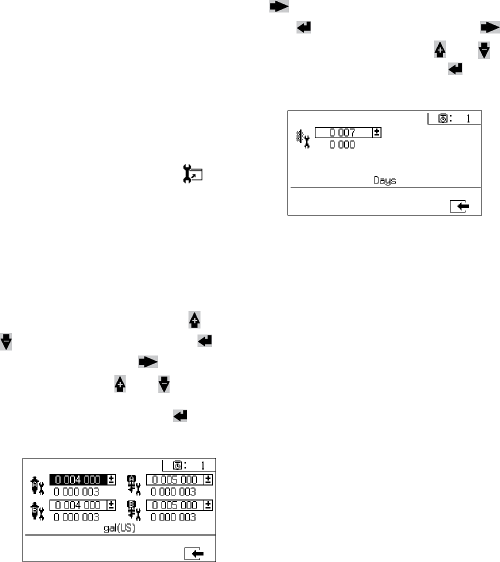
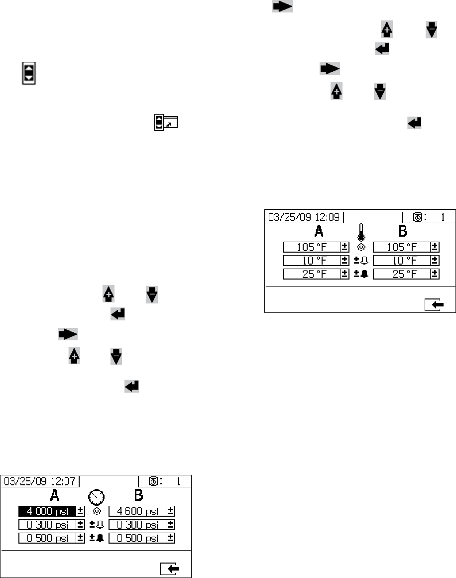
Set Sprayer Limits (Optional)
NOTE:
For details regarding the limits setup screens, see User
Limits Setup Screens, page 68.
To set and adjust pump pressure limits and temperature
limits:
1. Select in the Enable Setup 2 screen. See
Enable Setup Screens, page 66, for instructions.
2. From the Home Setup screen press to jump
to the limits screens.
3. Follow the instructions in Set Pressure Limits and
Set Temperature Limits.
Set Pressure Limits
Use the following instructions to set pressure limits for
each pump that if met will issue an advisory and/or
warning.
To set pressure limits, press and to move
through each field, and press to make a field
selectable. Press to scroll through each pres-
sure digit, and press and to scroll through the
optional values. Continue this process until you reach
the desired pressure limit. Press to save.
NOTE:
The B pump pressure always runs 10-20% higher than
the A pump pressure.
Set Temperature Limits
Use the following instructions to set temperature limits
that if met will issue an advisory and/or warning.
Press to move to the temperature limits screen.
To set temperature limits, press and to move
through each field, and press to make a field
selectable. Press to scroll through each tempera-
ture digit, and press and to scroll through the
optional values. Continue this process until you reach
your desired temperature limit. Press to save the
value.
NOTE:
The allowable range for the temperature setpoint is 34° -
160°F (1° - 71°C).
Prime
312359J 27
Prime
Prime A and B Fluids
NOTE:
Do not install gun spray tip yet. To avoid splashing, use
the lowest pressure possible to prime.
1. Condition materials prior to adding to hoppers.
Ensure resin materials are thoroughly agitated,
homogenous, and pourable prior to adding to hop-
per. Stir hardeners back into suspension prior to
adding material to hopper.
2. Fill A and B reservoirs with proper materials. Fill A
side with major volume of material; fill B side with
minor volume of material.
3. Move recirculation lines to empty containers.
4. Open ball valves into pumps.
5. Turn mix manifold valves (AH, AJ) clockwise to
close them.
6. Turn on air supply. Set main pump air regulator (CD)
to 20 psi (138 kPa 1.38 bar).
7. Use manual pump run mode.
Wear gloves when using flush solvents and/or if fluid
temperature exceeds 110° F (43° C).
20 Gallon Hopper Shown
AJ
AH
CD
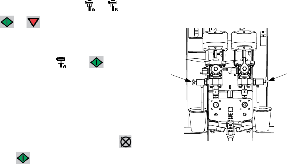
Prime
28 312359J
NOTE:
When run independently set to or . Press
and as needed to prime. Monitor containers
to avoid overflow.
8. Select Pump A . Press . Slowly turn
main pump air regulator (CD) clockwise to increase
air pressure until pump A starts. Dispense into pail
until clean fluid comes out of A. Close recirculation
valve.
NOTE:
When priming or flushing pumps, it is normal to get cav-
itation or pump runaway alarms. Clear alarms , and
press again as necessary. These alarms prevent
excessive pump speeds, which will damage pump pack-
ings.
9. Move recirculation line back to reservoir.
10. Repeat for B side.
11. Dispense a small amount of each material through
both sampling valves (AE, AF).
NOTE:
Open sampling valves slowly to avoid splashing.
12. Close both sampling valves (AE, AF).
NOTE:
If a remote mix manifold is used, disconnect hoses at
mix manifold and prime with material. Reconnect hoses.
AFAE
Prime
312359J 29
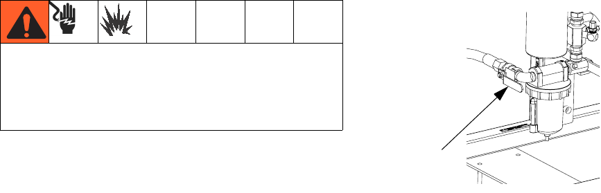
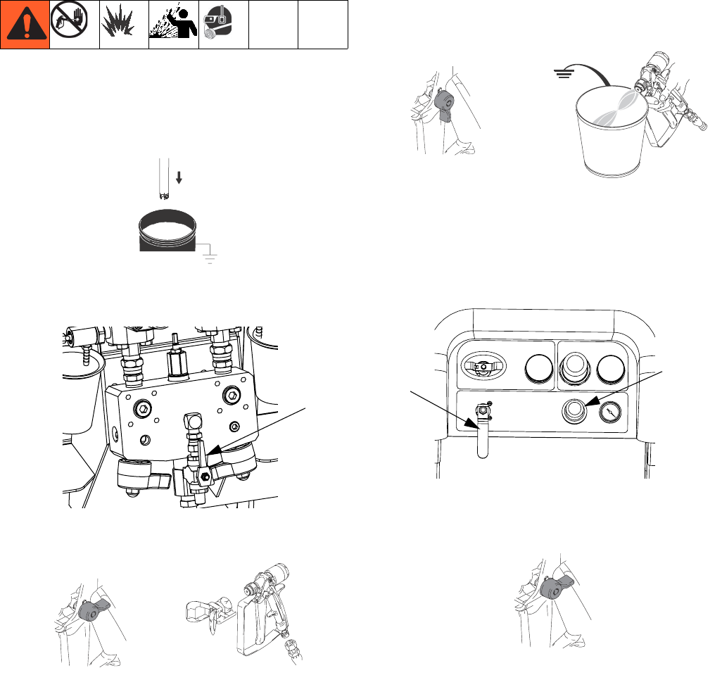
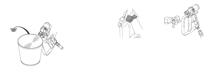
Prime Solvent Flush Pump
1. Connect flush pail ground wire to a metal pail of sol-
vent.
2. Place siphon tube in the pail of solvent.
3. Open solvent flush valve (AK) on mix manifold.
4. Ensure trigger lock is engaged. Remove spray tip.
5. Disengage trigger lock and trigger gun into a
grounded pail. Use a pail lid with a hole to dispense
through. Seal around hole and gun with a rag to pre-
vent splash back. Be careful to keep fingers away
from front of gun.
6. Open solvent pump air valve (CB). Pull out and
slowly turn solvent pump air regulator (CG) clock-
wise to prime solvent pump and push air out of mix
hose and gun. Trigger gun until all air is purged.
7. Close solvent pump air valve (CB) and trigger gun to
relieve pressure. Engage gun trigger lock.
AK
4)!
TI1948a
TI1949a
TI1950a TI1953a
CG
CB
TI1949a
Recirculate
30 312359J
Recirculate
Without Heat
If using a system that does not require heat, recircula-
tion is still required prior to spraying. Recirculation
ensures that any settled fillers are mixed in, the pump
lines are fully primed, and the pump check valves are
operating smoothly.
1. Follow Prime, page 27.
2. Close mix manifold valves (AH, AJ).
3. Ensure recirculation hoses are in the correct hop-
pers.
4. Open recirculation valves (AC, AD).
.
5. Select pumps to recirculate by pressing to
scroll through: , , or .
6. Turn on the main air shutoff valve (CA). Use system
air regulator (CD) to slowly increase the air pressure
to the pumps until they start running slowly.
7. If the pumps are running too quickly, close the
restrictor on each fluid line.
AH
AJ
AD
AC
CD
CA
Recirculate
312359J 31
8. Run the pumps until the material has reached the
desired temperature. See Heat Fluid, page 31.
9. Once desired temperature is reached, press .
10. Turn off the main air shutoff valve (CA).
11. Close recirculation valves (AC, AD).
12. See Spray, page 32.
NOTE:
If you circulate the A side pump at pressures greater
than 3000 psi (21 MPa, 210 bar), an advisory is issued
and the yellow LED on the display illuminates. This is a
reminder to select Spray mode prior to spraying and to
circulate at a lower pressure to avoid excessive pump
wear.
If you circulate the A side pump above 5200 psi (35.4
MPa, 354 bar), an alarm shuts the pump down to pre-
vent accidentally spraying material while still in circula-
tion mode.
With Heat
Using recirculation mode when heating the material is
required. Note the temperature at the top of the heater
(outgoing or back to hopper). When the thermometer
and display reach operating temperature, the material is
ready to spray.
Heat Fluid
To heat fluid evenly throughout the system:
1. Circulate fluid at approximately 1 gpm (10-20
cycles/min.) to raise temperature of hoppers to
80-90° F (27-32° C).
2. Decrease circulation rate to approximately 0.25 gpm
(5 cycles/min.) to increase the heater outlet temper-
ature to match the spray temperature.
NOTE:
Circulating fluid too quickly without decreasing the circu-
lation rate will increase only the hopper temperature.
Similarly, circulating fluid too slowly will increase only
the heater outlet temperature.
NOTE:
Agitate, recirculate, and heat material only as necessary
to avoid mixing air into the fluid.
CA
AC AD
Spray
32 312359J
Spray
NOTE:
After the first day of spraying follow Pressure Relief
Procedure, page 34, and then tighten throat seals on
both pumps and dosing valves.
1. If heaters are used, use heater junction box to turn
them on. To adjust heater temperature, refer to the
Viscon HP manual for instructions, and the Heat
Fluid section, page 31.
.
2. Close recirculation valves and mix manifold flush
valve. Open mix manifold valves A (blue) and B
(green).
.
3. Adjust pump air regulator to 30 psi (0.21 MPa, 2.1
bar).
4. Select . Press .
5. Disengage trigger lock and trigger gun into a
grounded metal pail. Use a metal pail lid with a hole
to dispense through to avoid splashing. Dispense
flush solvent out of mix hose until a well mixed coat-
ing flows from the gun.
6. Engage trigger lock. Install tip on gun.
7. Adjust air regulator (CD) to the necessary spraying
pressure and apply coating to a test panel. Look at
ratio screen to ensure it is reading the correct ratio.
Also, look at bar graph to ensure mix manifold
restriction adjustment is within optimal range. Refer
to Batch Ratio Dispense Test, page 43 and Adjust
B Machine Outlet Restriction, page 33.
8. Follow Flush Mix Manifold, page 36, or Park Fluid
Pump Rods, page 38, when you are finished spray-
ing or before potlife expires.
NOTE:
Mixed material potlife or working time decreases with
increased temperature. Pot life in hose is much shorter
than dry time of coating.
Wear gloves when using flush solvents and/or if fluid
temperature exceeds 110° F (43° C).
Fluid Heater A
Fluid Heater B
ti21275a
Hardener
Circulate
Resin
Circulate
Resin
Valve
(Blue)
Hardener
Valve
(Green)
TI1950a TI1953a
TI1949a
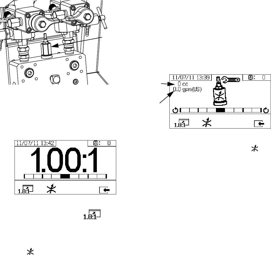
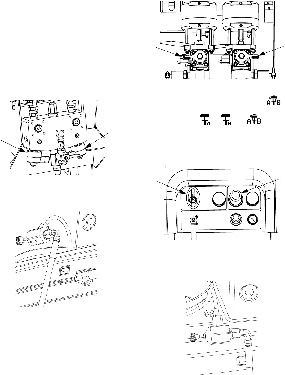
Adjust B Machine Outlet Restriction
312359J 33
Adjust B Machine Outlet
Restriction
Adjust the restriction stem on mix manifold, or on restric-
tor valve if mix manifold is remote, to optimize the B side
dosing control window. The goal is to create a near con-
stant flow on the A side and frequent dosing or a near
constant flow on the B side.
1. With material at normal spray temperature and tip
installed on spray gun, trigger gun for at least 10
seconds.
2. Navigate to Ratio Mode screen. See Ratio Mode,
page 71. Check bar graph.
The ratio bar graph is shown when is pressed.
This screen is used to show the accuracy of the spray
ratio. The bar should be in the center three segments
when the restrictor is adjusted.
3. Press to go to the restrictor adjustment screen.
NOTE:
• For remote mix manifolds, set the machine restrictor
first. Then close the remote mix manifold restrictor
to approximately the same setting, or until the
restrictor screen starts to move to the left.
• It is normal for the bar to move on the graph while
spraying. If the adjustment is too far off, you will
receive an alarm. If the ratio will not hold, you will
receive alarm R4B or R1B. See Alarm Codes and
Troubleshooting, page 52.
• If the bar swings back and fourth and you are using
feed pumps, the feed pressure may be too high.
Keep feed pressure under 250 psi (1.75 MPa, 17.5
bar). High pressure pumps receive a pressure boost
that is twice the pressure feed on the upstroke only.
High feed pressures can cause pressure swings
between A and B. The system will compensate, but
the bar graph will the show the swing.
The restrictor adjust bar graph is shown when is
pressed. This screen is used to adjust the restrictor.
• At maximum fluid flow, the bar should be in the cen-
ter.
• At flows less than maximum, the bar should be on
the right side.
• The bar should never be on the left.
• Configure the system at maximum fluid flow. Then
turn the restrictor clockwise if the bar graph is on the
right and counter-clockwise if the bar graph is on the
left.
NOTE: A pump dosing size, shown on the upper left cor-
ner, will be minimum when the restrictor is adjusted cor-
rectly. Once the restrictor is set for a given ratio and
material, it should be locked in place and left alone.
Mix Manifold
Restriction
Stem
Resin
dosing
size
Combined
flow rate
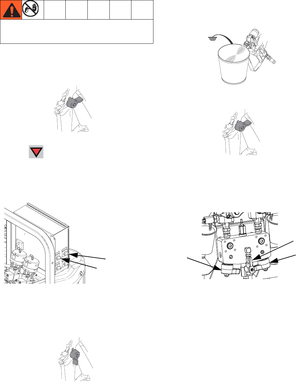
Pressure Relief Procedure
34 312359J
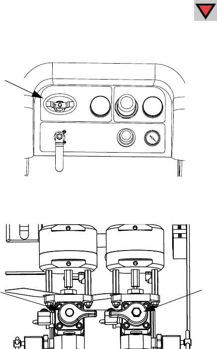
Pressure Relief Procedure
Relieve A and B Fluid Pressure
1. Engage trigger lock.
2. Press .
3. If fluid heaters are used, shut them off using the
controls on the heater control box or the heater
power junction box.
.
4. Shut off feed pumps, if used.
5. Remove spray tip and clean.
6. Disengage trigger lock.
7. Hold a metal part of the gun firmly to a grounded
metal pail with a splash guard in place. Trigger gun
to relieve pressure in material hoses.
8. Engage trigger lock.
Relieve Pump Fluid Pressure and Flush Mix
Hose
9. Close mix manifold valves (AH, AJ), then open sol-
vent flush valve (AK) on mix manifold.
Follow Flush Mixed Material when you stop spraying
or dispensing; and before cleaning, checking, servic-
ing, or transporting equipment.
TI1949a
Fluid Heater A
Fluid Heater B
ti21275a
TI1950a
TI1953a
TI1949a
AK
AJ
AH
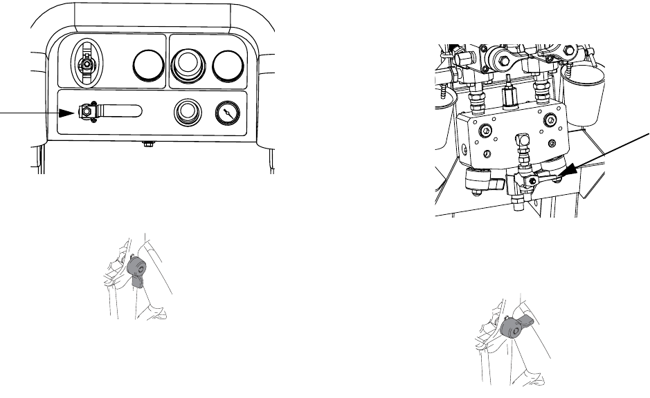
Pressure Relief Procedure
312359J 35
10. Open solvent pump air control valve (CB). Use low-
est pressure needed to flush material out of hose.
11. Disengage trigger lock.
12. Hold a metal part of the gun firmly to a grounded
metal pail with a splash guard in place. Trigger gun
to flush mixed material out of line with clean solvent.
13. Shut off solvent pump air control valve (CB).
14. Disengage trigger lock.
15. Close solvent flush valve (AK) on mix manifold.
16. Release any residual gun pressure and engage trig-
ger lock.
CB
TI1950a
AK
TI1949a
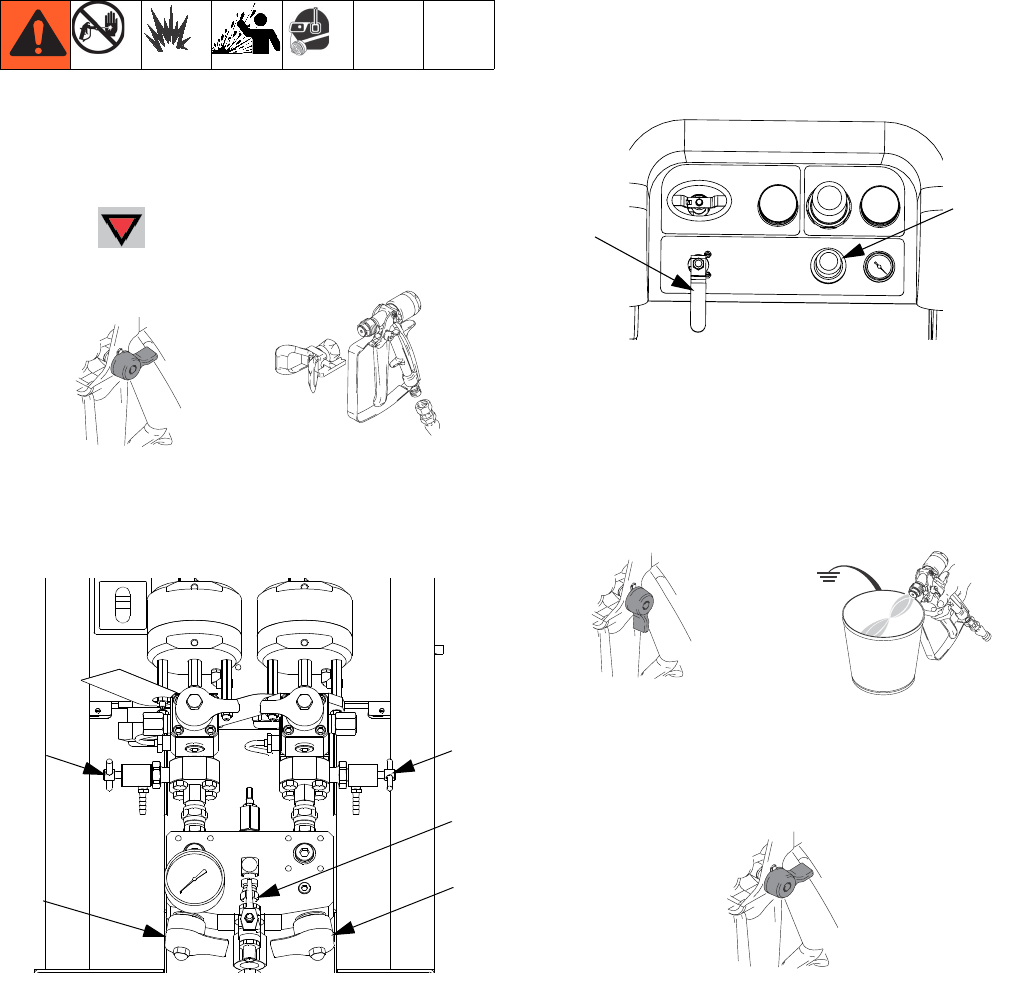
Flush Mixed Material
36 312359J
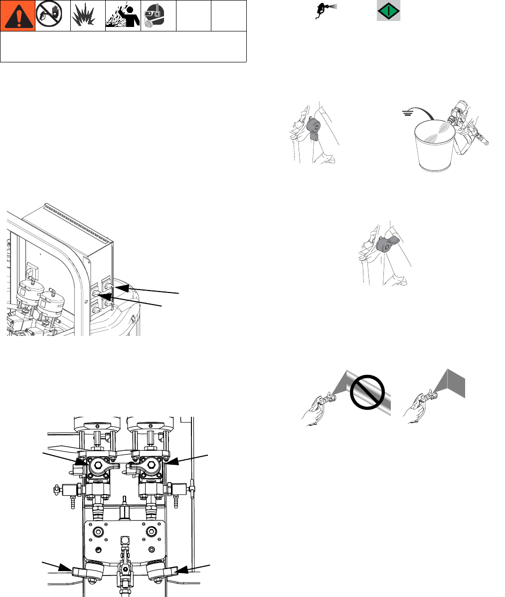
Flush Mixed Material
Flush Mix Manifold
Use Solvent Pump
1. Press to turn off system. Engage trigger lock.
Remove spray tip.
2. Ensure sampling valves (AE, AF) and mix manifold
valves (AH, AJ) are closed.
3. Open solvent shutoff valve (AK) at mix manifold.
4. Open solvent pump air valve (CB). Pull out and
slowly turn solvent pump air regulator (CG) clock-
wise to increase air pressure. Use lowest possible
pressure.
.
5. Disengage trigger lock and trigger gun into a
grounded pail. Use a pail lid with a hole to dispense
through. Seal around hole and gun with a rag to pre-
vent splash back. Be careful to keep fingers away
from front of gun. Flush out mixed material until
clean solvent dispenses.
6. Engage trigger lock.
4)!
TI1949a TI1948a
AE AF
AJ
AH
AK
CG
CB
TI1950a TI1953a
TI1949a
Flush Mixed Material
312359J 37
7. Close solvent pump air valve (CB) and solvent shut-
off valve (AK) at mix manifold. Trigger spray gun to
relieve pressure.
8. Follow Pressure Relief Procedure, page 34.
9. Engage trigger lock.
10. Disassemble and clean spray tip with solvent by
hand. Reinstall on gun.
AK
TI1949a
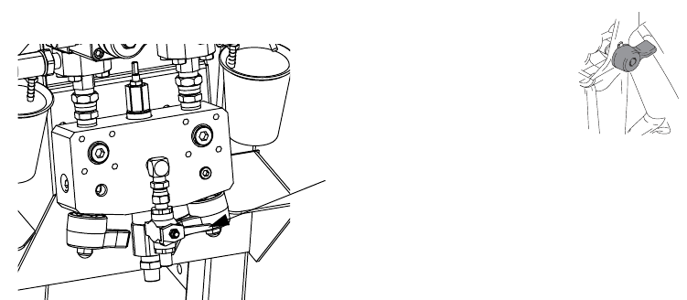
Park Fluid Pump Rods
38 312359J
Park Fluid Pump Rods
1. Relieve pressure. See Pressure Relief Procedure,
page 34.
2. Press .
3. Turn recirculation valves (AC, AD) counter clockwise
to open them. Each pump will run through recircula-
tion until they reach the bottom stroke, and then
stop.
4. When each blue pump LED turns off, close the cor-
responding circulation valve.
5. Shut off main pump air valve (CA) and air supply to
entire system.
ADAC
ADAC
CA
CB
Shutdown Entire System
312359J 39
Shutdown Entire System
Follow this procedure prior to servicing equipment or
shutdown.
1. Follow Flush Mixed Material, page 36. Use a metal
pail lid with a splash guard to avoid splashing.
2. Engage trigger lock, turn off air regulator, and close
main air shutoff valve. Remove spray tip.
3. For overnight shutdown:
•Follow Park Fluid Pump Rods on page 38.
• Cap fluid outlets to keep solvent in the lines.
• Fill pump A and B packing nuts with throat seal
liquid (TSL).
TI1953a
4)!
TI1949a TI1948a
System Verification
40 312359J
System Verification
Graco recommends running the following tests daily.
Mix and Integration Tests
Use the following tests to check for proper mix and inte-
gration.
Butterfly Test
At low pressure, normal flow rate, and without a spray tip
installed, dispense a 1/2 in. (12.7 mm) bead of material
onto foil until multiple changeovers of each pump have
occurred. Fold the sheet of foil over the fluid then peel it
back and look for unmixed material (appears mar-
ble-like).
Curing Test
Spray a single continuous pattern on foil at typical pres-
sure setting, flow rate, and tip size until multiple change-
overs of each pump have occurred. Trigger and
de-trigger at typical intervals for the application. Do not
overlap or cross over your spray pattern.
Check curing at various time intervals, listed on the
material data sheet. For example, check for dry to touch
by running your finger along the test pattern’s entire
length at the time listed on the data sheet.
NOTE:
Spots that take longer to cure indicate insufficient inte-
gration.
Appearance Test
Spray material onto metal substrate. Look for variations
in color, gloss, or texture that may indicate improperly
catalyzed material.
Pump and Metering Test
This test checks the following four items and should be
run every time a new job is started, or if there is a sus-
pected problem.
• Verifies that the pumps installed match the pumps
selected on the Setup screen by dispensing exactly
750 ml of each material.
• Verifies that each pump holds fluid against the pump
inlet valve by stalling on the down stroke.
• Verifies that each pump holds fluid against the pump
piston valve and packings by stalling on the
upstroke.
• Verifies that each metering valve holds fluid, and
that there are no external leaks between the pump
and metering valve.
• Verifies that the recirculation valves (AC, AD) are
closed and do not leak.
This test will dispense 750 ml of component A, and then
750 ml of component B. Dispense into separate cups so
the fluid can be returned to the supply tanks.
NOTE:
During each dispense the flow will stop once to stall the
upstroke, once to stall the downstroke, and then it will
finish the dispense. Do not close the sampling valve until
the third flow stops and the blue pump light (DK) goes
out.
1. Enter Test mode in the run (fluid control) screen.
See Test Screens on page 71. Select to
run pump test.
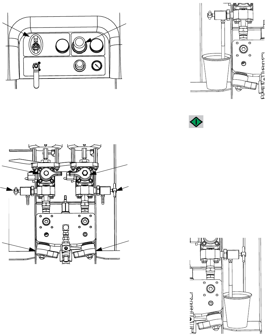
System Verification
312359J 41
2. Set main pump air regulator (CD) pressure to zero.
Open main pump and air valve (CA). Adjust main
pump air regulator (CD) pressure to 50 psi (0.35
MPa, 3.5 bar).
3. Dispense fluid A:
a. Close recirculation valves (AC, AD), mix mani-
fold valves (AH, AJ), and both sampling valves
(AE, AF).
.
b. Place a clean 1 quart (1000 cc) container under
sampling valve A (AE).
c. Press . Pump A light (DK) comes on.
d. Slowly open and adjust sampling valve A (AE)
to achieve desired flow. Pump stops automati-
cally; twice during test and again when dis-
pense completes. Pump A light (DK) turns off,
Pump B light (DK) turns on.
4. Close sampling valve A (AE).
5. Dispense fluid B as follows:
a. Place a clean 1 quart (1000 cc) container under
sampling valve B (AF).
CD
CA
AD
AF
AJ
AC
AE
AH
System Verification
42 312359J
b. Slowly open and adjust sampling valve B to
achieve desired flow. Pump stops automatically;
twice during test and again when dispense
completes. Pump B light (DK) turns off.
c. Close sampling valve B (AF).
6. Compare fluid amounts in containers; they should
be equal at 750 ml (25.3 fl. oz.) each. Repeat test if
fluids are not equal. If problem persists, see Alarm
Codes and Troubleshooting, page 52
.
7. Return fluid used in test to corresponding fluid sup-
ply container.
Confirm Pump Test
The Confirm Pump Test screen displays when the pump
test completes without error. This screen displays the
target volume of material dispensed into each beaker
from each pump.
System Verification
312359J 43
Batch Ratio Dispense Test
NOTE:
This test dispenses a calculated volume of each fluid
based on ratio. The two fluids combined equal the batch
size selected.
Follow this procedure to dispense a batch (into one con-
tainer) for touch-up work or to verify a ratio setting (use
separate containers for fluids A and B).
Dispense into a container with graduations no greater
than 5% of each component. If the ratio is known by
weight, use a scale for greatest accuracy.
1. Enter Test mode in the run (fluid control) screen.
See Test Screens on page 71. Select to run
batch dispense test.
2. Adjust dispense amounts from 500 ml to 2000 ml (in
250 ml increments) by pressing to open the
drop-down box. Then press and to select
the desired value. Press to select that value.
3. Set main pump air regulator (CD) pressure to zero.
Open main pump and air valve (CA). Adjust main
pump air regulator (CD) pressure to 50 psi (0.35
MPa, 3.5 bar).
4. Close recirculation valves (AC, AD), mix manifold
valves (AH, AJ), and sampling valves (AE, AF).
.
5. Place a clean container under sampling valve A
(AE).
6. Press . Pump A light comes on.
CD
CA
AE AF
AJ
AH
AD
AC
System Verification
44 312359J
7. Dispense fluid A. Slowly open and adjust sampling
valve A (AE) to achieve desired flow. The pump
stops automatically when dispense completes.
Pump A light (DK) turns off, Pump B light (DK) turns
on.
8. Close sampling valve A (AE).
9. Dispense fluid B as follows:
a. Batch dispense: move container under sam-
pling valve B (AF).
Ratio check: place clean container under sam-
pling valve B (AF).
b. Slowly open and adjust sampling valve B (AF)
to achieve desired flow. The pump stops auto-
matically when dispense completes. Pump B
light (DK) turns off.
c. Close sampling valve B (AF).
10. Batch dispense: stir material until mixed.
Ratio check: compare A and B fluid dispensed.
Confirm Batch Dispense Test
The Confirm Batch Dispense Test screen displays when
the batch dispense test completes without error. This
screen displays the selected ratio between the pumps
and the volume of material dispensed from each pump.
The gray at the bottom of the beaker represents the vol-
ume of material dispensed by pump A and the black at
the top of the beaker represents the volume of material
dispensed by pump B.
Down Stream Valve Leak Test
This test confirms or troubleshoots leaks in components
located down stream of the dosing valves. Use this test
to detect closed or worn valves, and to detect leaks in
circulation valves installed at a remote mix manifold.
1. Close both mix manifold valves downstream of the
dosing valves.
2. Close recirculation valves (AC, AD).
3. Enter Test mode in the run (fluid control) screen.
See Test Screens on page 71. Select to run
down stream valve leak test.
4. Select . Press . Ensure dosing valves
(AA, AB) are open by verifying blue LEDs are illumi-
nated for both dosing valves.
5. If test is successful, both pumps will stall against the
down stream valves when the dosing valves (AA,
AB) are open. If any movement is detected in the
pumps after stalling, an alarm is issued indicating
which side has a leak.
System Verification
312359J 45
XM Setup and Troubleshooting Guide
The following setup information will help ensure the system is setup properly. See the XM repair-parts manual for trouble-
shooting and repair instructions.
Grounding
• Ground system to a true earth ground.
• Ensure incoming power is grounded.
Air Supply
• Use at least a 3/4 in. (19mm) ID air hose, no longer
than 50 feet (15m).
• Ensure the first gauge (supply) stays above 80 psi
(0.55 MPa, 5.5bar) while spraying.
• Ensure that the pump spray pressure regulator is set to
at least 35 psi (2.4 bar) for spraying.
• Ensure that the solenoid air filter/regulator behind the
air panel is set to at least 80-85 psi.
• Check that the air filter element in the solenoid air fil-
ter/regulator behind the air panel is clean.
Calibration
• Adjust the B side fluid restrictor so that the calibration
bar graph averages center to right middle. This means
that the “B” dosing valve is open 25% to 75% of the
time.
• Ensure dosing valve needle packing nuts are not
adjusted too tight. They should be snug when there is
no fluid pressure on the valve.
• If feed pumps are used, don’t use more than 250psi
(17 bar). Excess pressure adds double the amount of
pressure on only the upstroke of the XM metering
pump.
Motor Icing
Air motors accumulate ice in the exhaust valving and muf-
fler under hot and humid conditions or under cold ambient
conditions. It can cause pressure loss or motor stalling.
• The ‘B’ fluid pressure should always be 15% to 30%
higher than ‘A’ pressure.
•A larger pressure difference indicates ‘A’ motor icing.
• A smaller or negative pressure difference indicates ‘B’
motor icing.
• Ensure that the NXT motor De-Ice bleed valves are
open to bleed warm air across the ice.
• Ensure that the motor is left active when not spraying
to keep the internal bleed air working. Leave the motor
active in Spray mode or Manual mode to keep the
bleed air on.
Restrictions or Lost Pressure
• Always use filter screens in the XM pump lowers. Filter
style pumps come with 60 mesh screens. Optional 30
mesh elements are also supplied.
• Always use a gun filter. 60 mesh is provided in the gun.
Check that the static mixer is clean.
• Early mix manifolds (2009) had a 40 mesh screen on
the B side. The screen could plug with materials that
have filled ‘B’ side fluids.
Remote Mix Manifold Applications
Ensure remote mix manifold outlet kit is installed. See XM
Repair parts manual. The kit includes outlet check valves
which isolate the pump pressure sensors from the outlet
hoses, and includes a ‘B’ side restrictor valve for the
machine outlet.
NOTE: Early remote manifold machines didn’t include
the ‘B’ restrictor valve from the factory.
• Ensure that the ‘A’ and ‘B’ outlet hose sizes volume
balanced close to the mix ratio. Unbalanced hose sizes
can cause off ratio slugs at the mix manifold during
pressure and/or flow transitions. See XM Mix Manifold
Kits manual.
• If a minimum of integration and mix hose is used,
ensure that “Fast Dosing” is selected in the setup
screens
Software Version
• Ensure all modules in the system use software from
same token. Different software versions may not be
compatible.
• The latest software version for each system can be
found at Tech Support at www.graco.com.
Empty and Flush Entire System (new sprayer or end of job)
46 312359J
Empty and Flush Entire System
(new sprayer or end of job)
NOTE:
• If the system includes heaters and heated hose,
turn them off and allow to cool before flushing. Do
not turn on heaters until fluid lines are clear of sol-
vent.
• Cover fluid container and use the lowest possible
pressure when flushing to avoid splashing.
• Before color change or shutdown for storage, flush
at a higher flow rate and for a longer time.
• To flush only the fluid manifold, see Flush Mixed
Material, page 36.
Guidelines
Flush new systems if coating materials will be contami-
nated by 10W oil.
Flush system when any of the following situations occur.
Flushing will help prevent materials from clogging the
line between hoppers and pump inlets.
• anytime sprayer will not be used for more than
one week
• if materials used will settle
• if using thixotropic resins that require agitation
Procedure
1. Follow Prime, page 27 and Flush Mixed Material,
page 36, as required. Engage trigger lock. Turn
main pump air regulator (CD) fully counter-clock-
wise to shut off.
2. Move circulation return lines to separate fluid con-
tainers to pump remaining fluid out of system.
3. Increase main pump air regulator (CD) pressure to
20 psi (138 kPa, 1.38 bar).
4. Select . Press .
NOTE:
When running pumps independently set to or
. Press and as needed to clean.
NOTE:
If sprayer does not start with static pressure, increase
air pressure by 10 psi (69 kPa, 0.7 bar) increments. To
avoid splashing, do not exceed 35 psi (241 kPa, 2.4
bar).
CD
Empty and Flush Entire System (new sprayer or end of job)
312359J 47
5. Open recirculation valves (AC, AD) for respective
pump dispense side. Run pumps until the A and B
reservoirs are empty. Salvage the material in sepa-
rate, clean containers.
NOTE:
When priming or flushing the pumps, it is normal to get
cavitation or pump runaway alarms. Clear the alarms
, and press again as necessary. These
alarms prevent excessive pump speeds that can dam-
age pump packings.
6. Wipe reservoirs clean, then add solvent to each.
Move circulation lines to waste containers.
7. Repeat Step 4 to flush through each side until clean
solvent exits recirculation hose.
8. Press . Move recirculation hoses back to reser-
voirs. Continue recirculating until system is thor-
oughly flushed.
9. Close recirculation valves (AC, AD) and open mix
manifold valves (AH, AJ). Dispense fresh solvent
through mix manifold valves and out gun.
10. Close mix manifold valves (AH, AJ).
11. Slowly open sampling valves (AE, AF) to flush sol-
vent through until clean. Close sampling valves.
Press .
12. Follow Park Fluid Pump Rods, page 38.
13. Remove pump fluid filters, if installed, and soak in
solvent. Clean and replace filter cap. Clean filter
o-rings and leave out to dry. Do not leave o-rings in
solvent.
14. Close main air valve (E).
NOTE:
Fill A and B pump packing nuts with TSL. Also, always
leave some type of fluid, such as solvent or oil, in the
system to prevent scale build up. This build up can flake
off later. Do not use water.
AC AD
AD
AF
AJ
AC
AE
AH
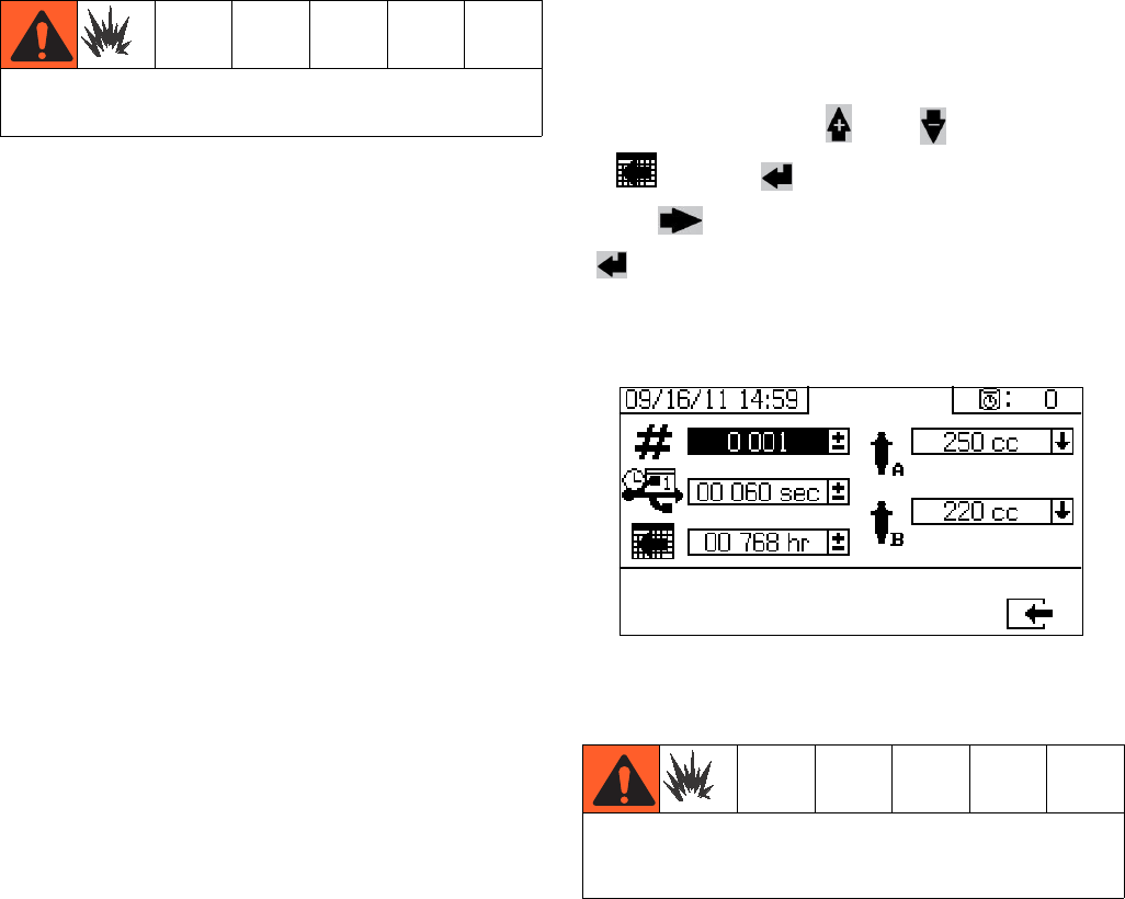
Download Data from USB
48 312359J
Download Data from USB
USB Logs
Spray Log 1
(Default log for download.) The spray log records key
data while the system is in spray mode. It records A and
B temperature, A and B pressure, A and B flow, A and B
batch totals, ratios, restrictor adjustments, alarm codes,
and commands.
By default, the spray log records data every 60 seconds.
This 60 second interval will record about 32 days of data
if spraying 8 hours per day, 7 days per week. To change
the default, see Download Setup, page 48. This log
can hold up to 18000 lines of data.
NOTE:
Once the spray log is full, new data automatically over-
writes old data.
NOTE:
After data in the spray log is downloaded it remains in
the USB module until it is overwritten.
Alarm Log 2
The alarm log records all alarm codes generated over a
two year period. This log should be used for trouble-
shooting purposes and cannot be deleted. This log can
hold up to 73000 lines of data.
Data Log 3
The data log records (every 120 seconds) all data that
occurs during spray mode over a two year period. This
log should be used for troubleshooting purposes and
cannot be deleted. This log can hold up to 84000 lines
of data.
NOTE:
The 120 second recording period cannot be adjusted.
Download Setup
Navigate to the System Setup screen. Change the num-
ber of hours of recorded data to download (default is
768 hours), by pressing and to move
to . Press to make the field selectable.
Press to scroll through each digit. Press
to save the new digit. Follow the same procedure
to change the time interval at which data will record
(default is 60 seconds). Exit the System Setup screen.
Download Procedure
1. Insert USB flash drive into USB port (DR). Use only
Graco-recommended USB flash drives; see Rec-
ommended USB Flash Drives, page 75.
NOTE:
Inserting the USB flash drive while the sprayer is run-
ning will stop sprayer operation.
Do not connect USB device in explosive atmospheres.
Remove sprayer from hazardous location or remove
the hazard before inserting, downloading, or removing
USB flash drive.
Download Data from USB
312359J 49
2. The USB download screen automatically displays,
and the selected log(s) automatically downloads.
The USB symbol flashes to indicate download is in
process.
NOTE:
To cancel download, press while in process. Wait
for USB icon to stop flashing, and then remove USB
flash drive.
3. The USB icon stops flashing when download com-
pletes. The box below displays , which indi-
cates the download was successful
4. Remove USB flash drive from USB port (DR).
5. Insert USB flash drive into USB port of computer.
6. The USB flash drive window automatically opens. If
it does not, open USB flash drive from within Win-
dows® Explorer.
7. Open Graco folder.
8. Open sprayer folder. If downloading data from more
than one sprayer, there will be more than one
sprayer folder. Each sprayer folder is labeled with
the corresponding USB serial number.
9. Open DOWNLOAD folder.
10. Open folder labeled with the highest number. The
highest number indicates the most recent data
download.
11. Open log file. Log files open in Microsoft® Excel® by
default. However, they can also be opened in any
text editor or Microsoft® Word.
NOTE:
All USB logs are saved in Unicode (UTF-16) format. If
opening the log file in Microsoft Word, select Unicode
encoding.
Never leave USB flash drive in USB port (DR).

Maintenance
50 312359J
Maintenance
Filters
Once a week check, clean, and replace (if needed) the
following filters. Be sure to follow the Flush Mixed Mate-
rial, page 36, prior to performing filter maintenance.
• Both pump filters; see manual 311762 for instruc-
tions.
• Main air inlet manifold filter; see manual 313289,
Replace Air Filter Element section, for instructions.
• Air regulator filter (5 micron) on air control assem-
bly; see manual 313289, Replace Air Filter Element
section, for instructions.
• B side mix manifold strainer (as required); see man-
ual 312749.
Seals
Once a week, check and tighten throat seals on both
pumps and dosing valves. Be sure to follow the Flush
Mixed Material, page 36, prior to tightening seals.
Cleaning Procedure
1. Ensure all equipment is grounded. See Grounding,
page 11.
2. Ensure the area where the sprayer will be cleaned is
well ventilated; and remove all ignition sources.
3. Turn off all heaters and allow equipment to cool.
4. Flush mixed material. See Flush Mixed Material,
page 36.
5. Relieve pressure. See Pressure Relief Procedure,
page 34.
6. Shutdown sprayer and turn off all power. See Shut-
down Entire System, page 39.
7. Clean external surfaces only using a rag soaked in
solvent that is compatible with the spray material
and the surfaces being cleaned.
8. Allow enough time for solvent to dry before using
sprayer.
Alarms
312359J 51
Alarms
View Alarms
When an alarm occurs the alarm information screen
automatically displays. It shows the current alarm code
along with a bell icon. It also shows the alarm location
with top and side views of the sprayer.
There are two levels of alarms: warnings and advisories.
A bell icon indicates an alarm. A solid bell icon with an
exclamation point and three audible alerts indicate a
warning. And an outlined hollow bell icon and a single
audible alert indicate an advisory.
Advisories are notifications that require attention but not
immediately. Alarms require immediate correction;
therefore, sprayer operation automatically stops.
This screen also shows diagnostic information. There
are three lines of data on the left side. The top line
shows the power supply or alternator power supply. This
should be between 23-25 Volts for power supply sys-
tems and 10-14 Volts for alternator systems. The middle
line shows the sensor voltage. This should be between
4.9-5.1 Volts.
The center of the screen shows linear sensor vertical
bar graphs and reed switch information. The A side
information is on the left and the B side information is on
the right. Linear sensor position is displayed on the bar
graph that goes up and down when the pump moves.
This bar graph should move from top to bottom to match
each pump stroke.
The state of the two reed switches in each air motor are
shown with the arrow above each vertical bar graph.
Diagnose Alarms
See Alarm Codes and Troubleshooting for causes
and solutions to each alarm code.
Clear Alarms
Press to clear alarms and advisories. From the
alarm information screen, press to return to the
run (fluid control) screen.
Icon Function
Moving up
Moving down
Top changeover
Bottom changeover
One reed switch signal is missing
Blank: No reed switch signal

Alarms
52 312359J
Alarm Codes and Troubleshooting
NOTE: See XM Plural-Component Sprayers Repair-Parts manuals for non-alarm based troubleshooting.
Alarm
Code Alarm Problem When Active Cause Solution
General Performance Alarms
R4B Ratio High B (Overdose B),
system delivering too much B
component.
Spray B Dosing valve not closing. Perform Pump Test to test for
leakage. See Pump and Meter-
ing Test, page 40.
Loosen valve packing nut. See
manual 313289.
Check air signal at valve top
Repair valve or air solenoid.
See manual 313289.
No B restriction at mix manifold. Increase B Restriction by turn-
ing B restrictor stem clockwise.
See Adjust B Machine Outlet
Restriction, page 33.
Pump filter plugged on A side. Clean filter. See manual
311762.
Use alternate 30 mesh screen.
See manual 311762 for part
number.
Inlet air dropping below 80 psi
(0.55 MPa, 5.5 bar) while spray-
ing. B dosing valve not closing
correctly.
Check air filters. See manual
313289.
Use larger air hose.
Use larger compressor.
Use smaller gun tips or less
guns to reduce flow rate.
Solenoid air regulator set below
80 psi (0.55 MPa, 5.5 bar)
Adjust air regulator.
R1B Ratio Low B (under dose B);
system delivering not enough
B component.
Spray B dosing valve will not open. Check for air signal to valve.
B mix manifold valve closed. Open green mix manifold valve.
Pump filter plugged on B side. Use alternate 30 mesh screen.
See manual 311762 for part
number.
Clean B pump outlet filter. See
manual 311762.
REC System detected five R4B
(ratio high B) or five R1B
(ratio low B) alarms within five
minutes. Sprayer shuts down
for five minutes to resolve
problem.
Spray See R4B or R1B alarm causes. See R4B or R1B alarm solu-
tions. Flush mixed material if
necessary, and purge off-ratio
mixed material in hose.
FHA
FHB
System detects pump move-
ment (fluid flow) when there
should not be.
Spray Recirculation valve or dosing
valve open or leaking for more
than five seconds.
Close or repair recirculation
valve, and run Pump Test. See
Pump and Metering Test,
page 40. See manual 313289 if
needed.

Alarms
312359J 53
R2D Dosing sizes are not opti-
mized.
Spray Dosing valve is operating near
high or low timing limits.
Adjust mix manifold B restrictor
stem clockwise or counter
clockwise as indicated by bar
graph on restrictor screen. See
Adjust B Machine Outlet
Restriction, page 33.
P4A
P4B
Pressure high. Always Fluid pressure is above maxi-
mum.
Decrease main air regulator.
DAA
DAB
Pump runaway, above 80
cpm for 10 sec.
Always No material in pump or lines; no
fluid restriction.
Refill material in tank or hoses;
install fluid tip.
DDA
DDB
Pump cavitation; dives more
than 1/2 of stroke.
Spray No fluid or valve closed. Refill supply and open inlet
valve.
Material is too cold or thick. Increase material temperature
to reduce viscosity. See Heat
Fluid, page 31. Shear material
with agitation to reduce viscos-
ity.
Pump inlet check valve not
closing.
Clear debris from check valve.
Or replace ball, seat, and seal.
Feed pump not providing mate-
rial.
Check feed pump (if used).
Inlet strainer plugged (if used). Check and clean strainer. See
manual 313289.
P1A
P1B
Pressure low. Spray, Pump
Test, Leak Test
Fluid pressure is below 1000
psi (7 MPa, 70 bar).
Increase main air regulator.
P4R Pressure high. Recirculation Pressure is above maximum
advisory limit of 3000 psi (21
MPa, 210 bar) on A side.
Decrease pump air regulator
pressure.
P5R Pressure high. Recirculation Pressure is above maximum
warning limit of 5200 psi (35.9
MPa, 359 bar) on A side.
Decrease pump air regulator
pressure.
P9A A pump pressure is abnor-
mally low compared to B
pump pressure.
Spray A air motor is icing up causing
restriction and lower fluid pres-
sure.
Open the air motor de-ice bleed
air controls. Allow ice to melt.
Dry compressed air. Heat com-
pressed air.
Use a smaller tip.
A pump is binding. Repair lower. See manual
313289.
A motor is hanging up. Repair air motor. See manual
313289.
P9B B pump pressure is abnor-
mally low compared to A
pump pressure.
Spray B air motor is icing up causing
restriction and lower fluid pres-
sure.
Open the air motor de-ice bleed
air controls. Allow ice to melt.
Dry compressed air. Heat com-
pressed air.
Use a smaller tip.
B pump is binding. Repair lower. See manual
313289.
Alarm
Code Alarm Problem When Active Cause Solution

Alarms
54 312359J
B3A Dosing size A advisory Spray The fluid dosing size is greater
than 35 cc when fast dosing is
turned off.
Adjust the B side fluid restric-
tion. See Adjust B Machine
Outlet Restriction, page 33.
The fluid dosing size is greater
than 20 cc when fast dosing is
turned on.
Decrease the air motor velocity
with a smaller tip.
B4A Dosing size A alarm Spray The fluid dosing size is greater
than 45 cc when fast dosing is
turned off.
Adjust the B side fluid restric-
tion. See Adjust B Machine
Outlet Restriction, page 33.
The fluid dosing size is greater
than 30 cc when fast dosing is
turned on.
Decrease the air motor velocity
with a smaller tip.
Pump Test (Daily Check Recommended)
DFA
DFB
Pump did not stall against
fluid pressure on up stroke
only.
Pump Test Pump piston check valve, pis-
ton packings, or dosing valve
are not holding fluid pressure.
Flush pump. See XM Setup
and Troubleshooting Guide,
page 45. Recheck. Remove,
clean, and repair lower. See
manual 313289.
DGA
DGB
Pump did not stall against
fluid pressure on down stroke
only.
Pump Test Pump inlet check or dose valve
is fouled, or damaged.
Remove inlet housing & clean
and inspect. See manual
313289.
DEA
DEB
Pump does not move in 10
minutes.
Park or Pump
Te s t
Recirculation valves were not
opened to allow flow.
Open recirculation valves.
General System Component Alarms
DJA
DJB
Pump motor linear sensor
has no signal.
Always No linear sensor signal from
motor.
Swap A and B sensors.
Replace sensor if problem fol-
lows sensor. See manual
313289.
Linear sensor plugged in while
power is on.
Power sprayer off and back on.
Do not plug in linear sensor
while power is on.
Bad connection inside fluid con-
trol module.
Replace fluid control module.
See manual 313289.
Pump motor linear sensor is
out of range.
Always Linear sensor is beyond range. Replace sensor or sensor mag-
net. See manual 313289.
Sprayer is not properly
grounded.
See Grounding, page 11.
DKA
DKB
Pump motor reed switch fail-
ure; missing signals from one
or both switches.
Always Bad motor cable connections,
or bad reed switch.
Swap A and B motor cables.
Replace cable if problem per-
sists. Otherwise replace reed
sensor assembly. See manual
313289.
Reed switch cable is plugged in
while power is on.
Power sprayer off and back on.
Do not plug in reed switch cable
while power is on.
Bad connection inside fluid con-
trol module.
Replace fluid control module.
See manual 313289.
P6A
P6B
Pressure sensor failure; no
signal.
Always Pressure sensor or cable is bad
on the side indicated.
Replace sensor and cable
assembly. See manual 313289.
Alarm
Code Alarm Problem When Active Cause Solution

Alarms
312359J 55
V1M Voltage low control. Always Voltage dropping below 9 Vdc
from power supply.
Change air filter in control filter
regulator. See manual 313289.
Check the pressure setting is
18 psi (0.13 MPa, 1.3 bar) on
turbine air regulator.
Check voltage on information
screen.
Turbine not spinning with air on. Replace air turbine cartridge.
See manual 313289.
N6C Display has no signal. Always No display communication sig-
nal.
Check cable connections.
Replace display.
See manual 313289.
Machine powered down in
spray mode.
Press stop button before turning
off power.
DLA A air motor reed switch signal
missing advisory.
Always Reed switch does not see the
air motor magnet.
Replace air motor reed switch
magnet.
Reed switches are bad. Replace air motor reed switch.
Prevent air motor icing. See
advisory P9A and P9B.
Air motor is icing up.
DLB B air motor reed switch signal
missing advisory.
Always Reed switch does not see the
air motor magnet.
Replace air motor reed switch
magnet.
Reed switches are bad. Replace air motor reed switch.
Prevent air motor icing. See
advisory P9A and P9B.
Air motor is icing up.
DMA A air motor linear sensor
jump advisory.
Always System ran out of fluid. Add fluid to the system.
Linear sensor is bad. Replace linear sensor.
DMB B air motor linear sensor
jump advisory.
Always System ran out of fluid. Add fluid to the system.
Linear sensor is bad. Replace linear sensor.
Optional User-Settable Maintenance Warnings
*MAA
*MAB
Maintain pump. Always, if enabled Pump usage exceeds user-set
limit. Maintenance due.
Service pump. See manual
313289.
*MEA
*MEB
Maintain dosing valve. Always, if enabled Dosing valve usage exceeds
user-set limit. Maintenance
due.
Service dosing valve. See man-
ual 313289.
*MG0 Maintain air filter. Always, if enabled Air filter exceeds user-set limit.
Maintenance due.
Service main air filter and con-
trol filter regulator.See manual
313289.
*P5A
*P5B
Pressure exceeded alarm
limits.
Spray Pressure exceeded high or low
alarm limits for more than 15
seconds.
Adjust pump pressure regulator,
change tips, or adjust target set
point.
Alarm
Code Alarm Problem When Active Cause Solution

Alarms
56 312359J
Optional User-Settable Spray Limits
*T5A
T5B
Temperature exceeded alarm
limits.
Spray Fluid temperature exceeded
high or low alarm limits for more
than four minutes.
If fluid temperature is too low,
return to circulation mode to
increase fluid temperature.
Adjust heater set point if
needed. See Heat Fluid, page
31.
If fluid temperature is too high,
lower heater set point, and
return circulation mode to cool.
See Heat Fluid, page 31.
Adjust temperature target set-
point. See Heat Fluid, page 31.
*P2A
P2B
Pressure exceeded advisory
limits.
Spray Pressure exceeded high or low
advisory limits for more than 15
seconds.
Same as P5A or P5B above.
*T2A
T2B
Temperature exceeded advi-
sory limits.
Spray Fluid temperature exceeded
high or low limits for more than
four minutes.
Same as T5A or T5B above.
*N4D Pot life timer expired. Mixed
fluid will cure in hoses, mixer,
and gun.
Spray Have not sprayed enough vol-
ume to keep fresh mixed fluid in
the integration hose, mixer,
whip hose, and spray gun.
Spray fluid, or flush. Resets
when you leave spray mode.
See Spray, page 32, or Flush
Mixed Material, page 36.
Alarm
Code Alarm Problem When Active Cause Solution

Alarms
312359J 57
Possible Alarms by Mode
The following table outlines the alarms that you may receive while operating the system. The alarms are categorized
according to each mode.
Mode Control Logic Alarms
Spray Dosing valves close for startup test; green light blinks. --
If fluid pressure is under 1000 psi (7 MPa, 70 bar), STOP. P1A
If pumps move (indicating internal leakage), STOP. FHA, FHB
If fluid pressure is more than 103% of allowed maximum, air motor shuts
off until fluid pressure drops.
None
If is pressure more than 110% of allowed maximum, STOP. P4B
Dosing valve A opens, and dosing valve B cycles to maintain ratio. --
A and B blue lights illuminate when dosing valves are operating. --
If there is not enough B component to hold ratio, dosing valve A closes
momentarily.
R2D
If A or B component is more than 5% off ratio setpoint, STOP. R1B, R4B
If A dose size is too large, STOP. B4A
A and B dosing valves close momentarily at each pump changeover. --
Park Both dosing valves open; A and B blue lights turn on. --
User opens circulation valves or sprays gun. When pump reaches bot-
tom stroke the blue light turns off.
--
If park does not complete in 10 minutes, turn off air to both motors. DEA, DEB
Circulation A and/or B dosing valves close and motor air turns on. --
If fluid pressure exceeds 3000 psi (21.0 MPa, 210 bar) on the A pump,
receive yellow light advisory.
P4A
If fluid pressure exceeds 5600 psi (39.2 MPa, 392 bar) on the A pump,
STOP.
P4A
If no movement in 10 minutes, turn off air to both motors. DEA, DEB
Pump Test Both dosing valves close; green light blinks. --
If fluid pressure is under 1000 psi (7.0 MPa, 70 bar), STOP. P1A, P1B
If pumps move (indicating leakage) STOP. FHA, FHB
Turn on A blue light, open A dosing valve, user opens sampling valve. --
Close A dosing valve on upstroke; check for no movement. DFA
Close A dose valve on down stroke; check for no movement. DGA
Open A dose valve and dispense total of 750 ml material, close valve,
turn off blue light.
--
Repeat for B side. DFB, DGB, DHB
If both pumps pass pump test, display shows two beakers of 750ml each. --
Batch Dispense Test User selects total volume desired. --
Open A dosing valve, turn on blue light, user opens sampling valve, turn
off blue light when complete.
--
Open B dosing valve, turn on blue light, user opens sampling valve, turn
off blue light when complete.
--
Display shows volume of A and B components at end of batch dispense
test.
--
Valve Test If fluid pressure is not 1000 psi (7 MPa, 70 bar), STOP. P1A
Check for no movement of pumps (stall within 10 seconds). FHA, FHB
Alarms
58 312359J
Alarm Code Key
Use the following table as a quick guide to determine alarm codes.
LED Diagnostic Information
The following LED signals, diagnosis, and solutions are the same for the display module, fluid control module, and
USB module. LEDs are located next to the module power cable.
What Alert Where
B Dose 1 Low A Material A
F Flow 2 Deviation B Material B
N Time 3 Deviation High C Controller
P Pressure 4 High D Dosing/Pot life
R Ratio 5 Limit warning M Power or Air supply
T Temperature 6 Sensor or connection failure R Recirculation
V Voltage 9 Unbalanced
D Pump A Pump runaway
D Pump diving/cavitation
E Pump time-out
F Pump failed to stall up
G Pump failed to stall down
H Pump failed to stall
J Linear sensor failure
K Directional switch failure
M Linear sensor jump
M Maintenance due A Pump
E Dosing valve
GFilter
Module Status LED Signal Diagnosis Solution
Green on System is powered up and power
supply voltage is greater than 11
Vdc.
-
Yellow Internal communication in progress -
Red solid Hardware failure Replace display module, fluid control
module, or USB module.
Red flashing fast Uploading software -
Red flashing slow Token error Remove token and upload software
token again.

Accessories and Kits
312359J 59
Accessories and Kits
20-Gallon Hopper Kit, 255963
One complete double-wall 20-gallon hopper. See man-
ual 312747 for more information.
Hopper Heater Kit (240V), 256257
For heating fluid in a 20-gallon hopper. See manual
312747 for more information.
Universal Hopper Fluid Inlet Kit, 256170
For connecting any of the four lower models included
with XM sprayer to a 20-gallon hopper. See manual
312747 for more information.
Universal Hopper Mounting Kit, 256259
For mounting a 20-gallon hopper to the side or back of
an XM sprayer. See manual 312747 for more informa-
tion.
Twistork® Agitator Kit, 256274
For mixing viscous materials held within a 20-gallon
hopper. See manual 312769 for more information.
T2 Feed Pump Kit, 256275
For supplying viscous material from a 20-gallon hopper
to an XM sprayer. See manual 312769 for more informa-
tion.
5:1 Feed Pump Kit, 256276
For supplying viscous materials from a 20-gallon hopper
to an XM sprayer. See manual 312769 for more informa-
tion.
7-Gallon Hopper and Bracket Kit,
256260 (Green)
24N011 (Blue)
One 7-gallon hopper and mounting brackets. Mounts to
the side or back of an XM sprayer. See manual 406699
for more information.
2:1 Drum Feed Kit, 256232
One T2 pump feed kit and one Twistork agitator kit for
mixing and supplying viscous materials from a with
55-gallon drum to an XM sprayer. See manual 312769
for more information.
5:1 Drum Feed Kit, 256255
One 5:1 pump feed kit and one Twistork agitator kit for
mixing and supplying viscous materials from a with
55-gallon drum to an XM sprayer. See manual 312769
for more information.
Hopper/Hose Heat Circulation Kit, 256273
For circulating heated water through 20-gallon hoppers,
heated hose, and Viscon HP heater. See manual
313259 for more information.
Not all accessories and kits are approved for use in
hazardous locations. Refer to the specific accessory
and kit manuals for approval details.
Accessories and Kits
60 312359J
Desiccant Dryer Kit, 256512
For use with 20-gallon hoppers. See manual 406739 for
more information.
Caster Kit, 256262
For mounting casters on XM sprayer frame. See manual
406690 for more information.
Hose Rack Kit, 256263
For mounting to side, front, or back of XM sprayer frame.
See manual 406691 for more information.
Lower Strainer and Valve Kit, 256653
For straining material from a feed pump to an XM
sprayer fluid inlet. See manual 312770 for more informa-
tion.
Electric Heated Hose Power Supply Kit,
256876
For monitoring and controlling fluid temperature in
low-voltage heated hoses. See manual 313258 for more
information.
5000 psi Two-Component Main Heated
Hose Set Kit
Electric heated hose set for adding additional sections.
Xtreme Pump Wetcup Wrench, 15T258
Xtreme Pump Filter Wrench, 16G819
10:1 Drum Feed Kit, 256433
For supplying highly viscous material from a 55-gallon
drum to an XM sprayer. See manual 312769 for more
information.
Shutoff/Check Valve Kit, 255278
For replacing shutoff valve or check valve. See manual
313343 for more information.
Alternator Conversion Kit, 256991
For converting an XM sprayer from wall power supply to
intrinsically safe alternator power supply. See manual
313293 for more information.
Mix Manifold Kit, 255684
See manual 312749 for more information.
Remote Mix Manifold and Carriage Kit,
256980
For converting to a remote mix manifold kit with a pro-
tective guard. See manual 312749 for more information.
Restrictor Valve Kit, 24F284
For B dosing outlet on remote mix manifold machines.
Use to convert early XM machines without the valve on
the B outlet.
Restrictor Valve Wrench, 126786
For adjusting restrictor valve. See page 33.
Part Description
248907 Heated hose set; 1/4 in. ID x 3/8 in. ID;
50 ft.
248908 Heated hose set; 3/8 in. ID x 3/8 in. ID;
50 ft.
Appendix A
312359J 61
Appendix A
User Interface Display
The user interface display is divided into three main
functions: Setup, Command, and Automatic.
Setup Functions (key “ON”)
The setup functions enable users to:
• set desired mix ratio;
• configure system settings;
• set potlife parameters;
• enable/disable functions, displays, and display
components;
• set which USB logs to download;
• schedule maintenance parameters for alarms
and advisories;
• and set pressure and temperature limits.
NOTE:
All setup functions, except for mix ratio, must be enabled
from the Enable Setup screens before users can change
or set configurations. See Enable Setup Screens, page
66, for instructions.
Command Functions (key “OFF” or removed)
The command functions enable users to:
• run pumps, including flush, circulate, and prime
procedures;
• park pumps so pump rods are down when not in
use;
• mix and spray;
•view mix ratio;
• run pump tests;
• run batch dispense ratio tests;
• run valve leak checks;
• view dispense totals;
• view alarms;
• diagnose alarms;
• and clear alarms.
Automatic Display Functions
The automatic display functions enable users to:
• issue potlife timer alarms
• and download USB logs.
Appendix A
62 312359J
Setup Mode Screens
Setup mode screens are divided into five major sections: home, limits, maintenance, enable, and system. The follow-
ing figure demonstrates the flow of the Setup mode screens beginning with the Home screen.
Limits Setup
Maintenance Setup
Enable Setup
System Setup
Home Version Control
Temperature Limits
Maintenance Setup 1 Maintenance Setup 2
Enable Setup 2
Enable Setup 1
System/USB/Pump Config.
Date/Time/Units
Potlife/Hose Length
Pressure Limits
(shown with factory default settings)
Appendix A
312359J 63
Home Setup Screens
Home
Home is the first screen that displays in Setup mode. It
shows the current pump ratio, and enables users to
change the mix ratio and access the following screens:
system setup, enable/disable functions, maintenance
setup, and limits. Refer to the following table for more
details.
.
Version Control
This screen displays the versions and/or status of the
system components. Refer to the following table for
details. To access this screen, press from the
Home Setup screen.
Icon Function
Increase or decrease mix ratio. Press
and to change the mix ratio.
Press to jump to system setup screens.
Press to jump to functional enable/disable
setup screens.
Press to jump to maintenance setup
screens.
Press to jump to pressure and temperature
limits setup screens.
Icon Function
Display module version (Vs)
Fluid control module version (Vs)
USB version (Vs)
USB Configuration (Vc)
ATotal amount dispensed by pump A
BTotal amount dispensed by pump B
A+B Total amount dispensed by pumps A and B
Number of hours system has been running
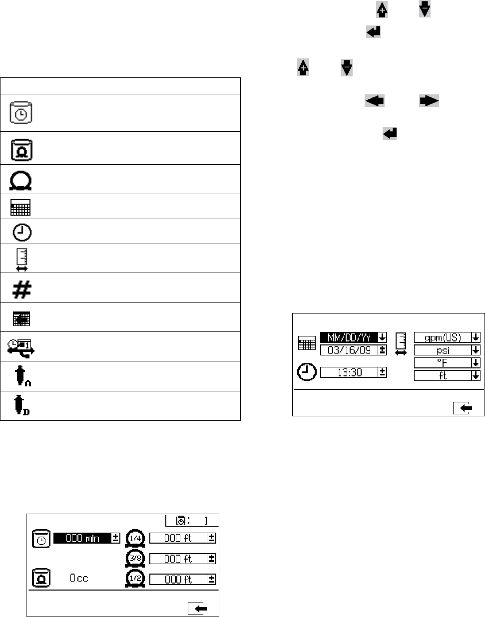
Appendix A
64 312359J
System Setup Screens
System Setup enables users to configure system set-
tings for fluid control and operator interaction. Refer to
the following table for details.
NOTE:
System settings must be enabled from the Enable Setup
screens before users can change or set configurations.
See Enable Setup Screens, page 66, for instructions.
Potlife/Hose Length
This screen enables users to set the potlife timer and
enter the hose inside diameter and length of each mixed
material hose specific to the system. The potlife time
displays in the upper right corner.
Set Potlife/Hose Length
To set the potlife timer and enter the mixed material
hose dimensions, press and to move through
each field, and press to make a field selectable.
Press and to select preferred units of mea-
surement for the potlife timer and length of each mixed
material hose. Press and to move to the
next digit in each field. Once the measurement unit in
the field is correct, press to save that measure-
ment.
When the fluid flow stops the displayed time counts
down in one minute intervals. The timer automatically
resets when the calculated mixed fluid volume is dis-
pensed.
Date/Time/Units
This screen enables users to set day, time, and units
that will be displayed on each screen.
Icon Function
Set number of minutes before mixed mate-
rial will set in hose. Resets after material
volume set by user is passed through hose.
Indicates total hose volume. Always dis-
played in cc units.
Set length of hose after mix manifold. Used
to indicated total hose volume.
Set calendar date and format.
Set time.
Set units of measurement desired for dis-
play, such as fluid and temperature.
Set sprayer number if using more than one
sprayer.
Set number of hours of recorded data to
record to USB data logs.
Set how often data will record to USB spray
logs.
Select resin pump size for A side.
Select hardener pump size for B side.
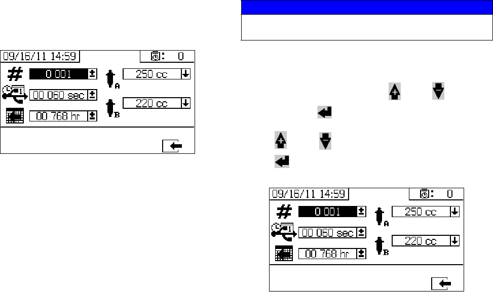
Appendix A
312359J 65
System Number and USB Settings
This screen enables users to set the sprayer number if
using more than one sprayer. It also enables users to
configure the number of hours downloaded to external
USB flash drive and how often the data will record. See
Set System Settings (Optional), page 24, for instruc-
tions.
Pump Configuration
Users can change the pump size that is specific to the
system if the pump box is selected on Enable Setup 1,
page 66.
Set Pump Sizes
To change the pump size, press and to select
the field. Press to open the drop down field.
Press and to select the preferred pump size.
Press again to save the change.
NOTICE
Changing the pump size settings may cause the system
to spray off ratio.
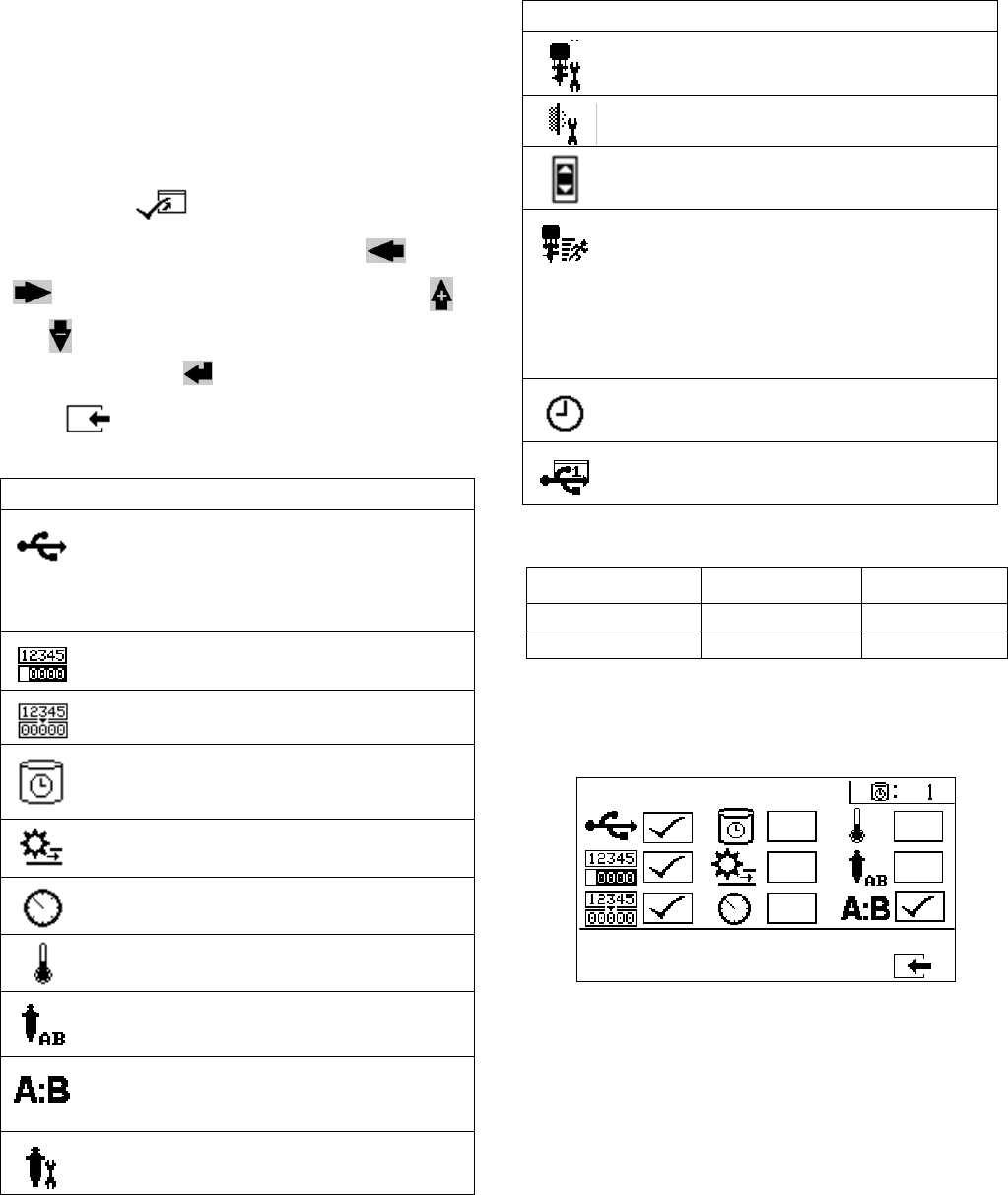
Appendix A
66 312359J
Enable Setup Screens
Enable Setup allows users to enable and disable func-
tionalities, screens, and USB download log files.
Checked boxes indicate the function, screen, or log file
is active. Refer to the following table for details.
To enable and disable functionalities, screen, and USB
log files, press from the Home Setup screen.
Once in the Enable Setup screen, press and
to scroll through each subscreen. Press
and to scroll through each field within the sub-
screens, and press to enable or disable each.
Press to return to the Home Setup screen
Fast Dosing Function
Enable Setup 1
(Shown with factory default settings.)
Icon Function
USB data download function. Disable this
function to prevent operators from chang-
ing USB settings.
NOTE: Even if this function is disabled,
selected USB logs will still be downloaded.
Enable or disable totalizer screens.
Enable or disable batch totalizer clear func-
tion.
Display potlife timer on all screens.
Enable or disable potlife timer setup
screen.
Display flow rates on run screens
Display A and B pressures on run screens.
Display A and B temperatures on run
screens.
Enable or disable ability to change pump
size in system setup screens.
Enable or disable ratio screen. If enabled,
ratio screen will automatically display after
sprayer runs for 10 seconds.
Enable or disable pump maintenance setup
screens.
Icon Function
Enable or disable dosing valve mainte-
nance setup screen.
Enable or disable incoming air filter mainte-
nance setup screen.
Enable or disable limits (pressure and tem-
perature) screens.
Fast dosing function. Enable function to
minimize B side dose size and increase
dosing rate. See table below.
Use this function with short integration
hose. The system will attempt to hold the
dosing sizes below the advisory level.
Display time on all screens.
Enable or disable USB log files (1-3) to
download.
Fast Dosing Advisory B3A Alarm B4A
on 20 cc 30 cc
off 35 cc 45 cc
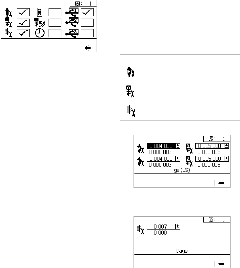
Appendix A
312359J 67
Enable Setup 2
(Shown with factory default settings.)
Maintenance Setup Screens
The maintenance setup 1 screen enables users to set
maintenance setpoint amounts for pumps and dosing
valves. The maintenance setup 2 screen enables users
to schedule the number of days between changing the
main incoming air filter before a reminder advisory will
sound.
The number displayed below each selectable field indi-
cates the amount of material dispensed, counting up to
the setpoint requiring maintenance.
Maintenance Setup 1
Maintenance Setup 2
Icon Function
Set amount of material moved through
pump that will result in a maintenance
warning.
Set amount of material moved through dos-
ing valve that will result in a maintenance
warning.
Set number of days between changing the
main incoming air filter before a reminder
advisory is issued.
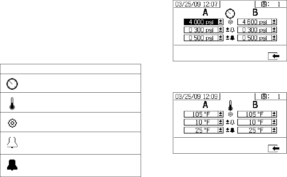
Appendix A
68 312359J
User Limits Setup Screens
User Limits Setup enables users to set and adjust pres-
sure and temperature limits for both pumps, including
limits that will issue advisories and alarms. Refer to the
following table for details.
NOTE:
The allowable range for the temperature setpoint is 34° -
160°F (1° - 71°C). If the temperature or pressure set-
point is zero, pressure limits and alarms are disabled.
Process Pressure Limits (for spray mode)
Process Temperature Limits (for spray mode)
Icon Function
Set and adjust pressure limits for both
pumps.
Set and adjust high and low temperature
limits for both pumps.
Set target pressure or temperature.
Set and adjust limits that if exceeded will
issue an advisory. Used with pressure and
temperature limits.
Set and adjust limits that if exceeded will
issue a alarm. Used with pressure and
temperature limits.
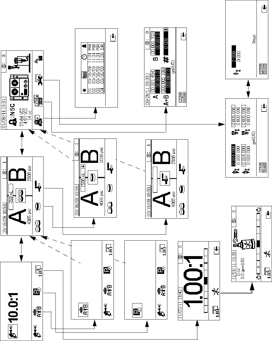
Appendix A
312359J 69
Operator Command Functions Screens
Command mode screens are divided into three major sections: run (fluid control), test, and alarm control. The follow-
ing figure demonstrates the flow of the Command mode screens beginning with the run (fluid control) screens.
Run (Fluid Control) Screens Test Screens Alarm Control Screens
Alarm Information
Alarm Log
Totalizer
Maintenance 2
Maintenance 1
Valve Test
Batch Test
Pump Test
Spray Mode
Ratio Screen
Park Mode
Pump Mode
Restrictor Screen
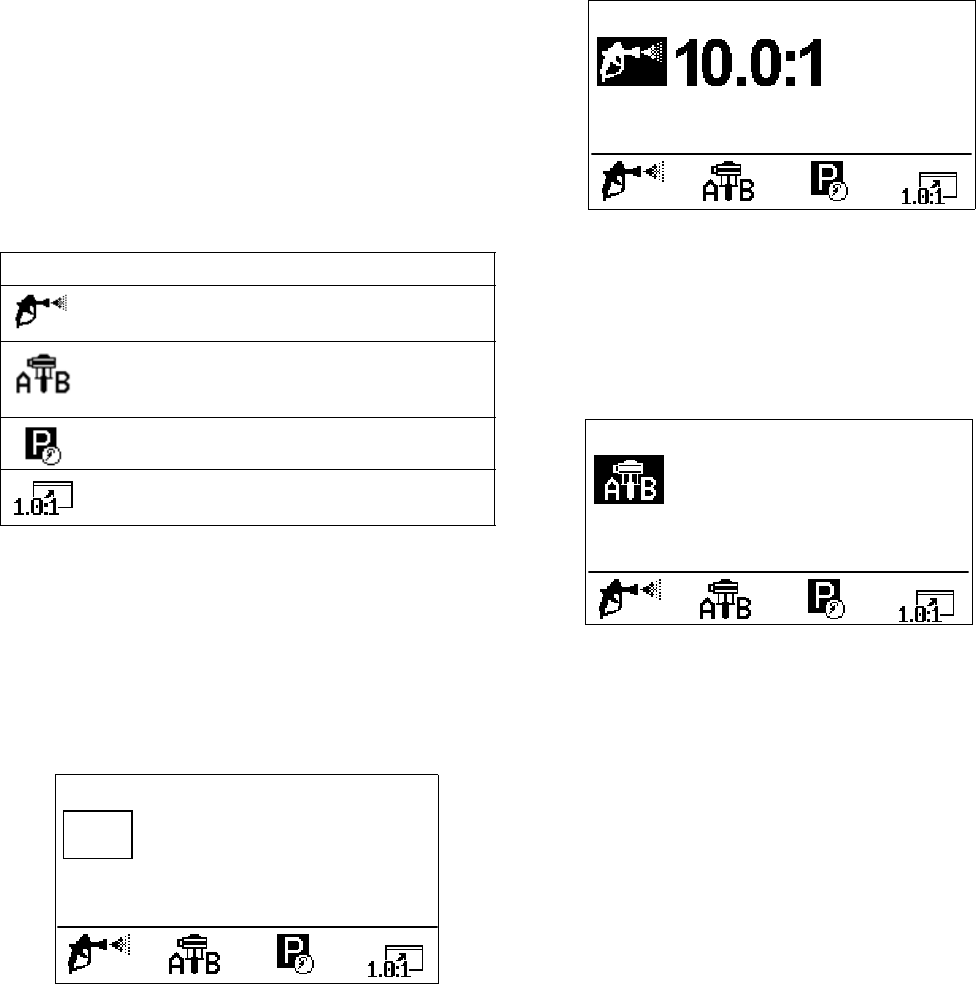
Appendix A
70 312359J
Run (Fluid Control) Screens
Run (fluid control) is the first screen displayed at power
on. It enables users to spray material, and operate and
park pumps. Run consists of two screens: power
on/enter and ratio mode.
The power on/enter screen cycles through power on
mode, spray mode, and pump mode. It always displays
the current ratio setpoint, and may also display: pres-
sure, temperature and flow rate if these functions are
selected.
The ratio screen displays the current ratio and monitors
the B side restriction adjustment.
Power On/Enter Mode
Power On/Enter Mode is the default screen when users
enter Fluid Control.
NOTE:
This screen remains blank until a mode is selected.
Spray Mode
Users must be in this mode to spray or proportion mate-
rial. Press the button below the spray icon to enter this
mode.
Pump Mode
Users must be in this mode to operate pumps for prim-
ing or flushing. Press the button below the pump icon to
enter this mode. Continue pressing the pump icon but-
ton to cycle through pump A, pump B, and both pumps.
Icon Function
Spray: proportion and spray material.
Run pumps: operate both pumps or oper-
ate each pump independent from the other
(priming, flushing).
Park Pumps: runs pump to bottom of the
stroke.
Ratio: jump to ratio screen.
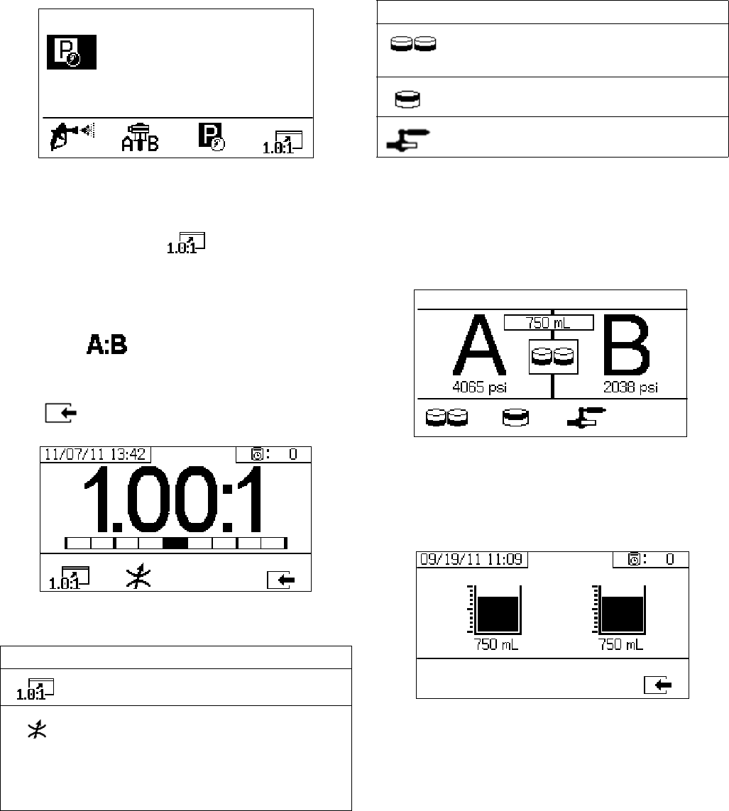
Appendix A
312359J 71
Park Mode
Users must be in this mode to park fluid rod pumps at
the bottom of the stroke. Press the button below the
park icon to enter this mode.
Ratio Mode
Displays the current ratio or the restrictor screen. To
access this screen, press The bar graph indi-
cates whether the B restriction adjustment should be
turned clockwise or counter clockwise. See Adjust B
Machine Outlet Restriction, page 33.
NOTE: If the field is enabled on the Enable
Setup screen, the Spray Mode screen will be replaced
by the bar graph screen after 10 seconds of spray time.
Press to return to the Spray Mode screen.
Restrictor Screen
Test Screens
Test screens enable users to run batch dispense tests,
pump tests, and down stream valve leak tests.
Pump Test
This screen enables users to dispense a fixed 750 ml
volume of material from each pump. When the pump is
active it flashes in black on the screen. When the pump
completes dispensing it displays gray on the screen.
Confirm Pump Test
This screen displays when the pump test completes
without error. This screen displays the target volume of
material dispensed into each beaker from each pump.
Icon Function
Display Ratio: show the accuracy of the
fluid mix ratio.
Display Restrictor Adjust: Adjust the restric-
tor to optimize the mix ratio.
• At the maximum fluid flow, the bar
should be in the center.
• At less than maximum flow, the bar
should be on the right side.
Icon Function
Pump Test: dispenses 750cc of each A and
B; verifies pump selection, operation, and
metering.
Batch Dispense: dispenses proportioned
amounts of A and B with a selectable total.
Down Stream Valve Leak Test: test if valves
after the dosing valves hold pressure.
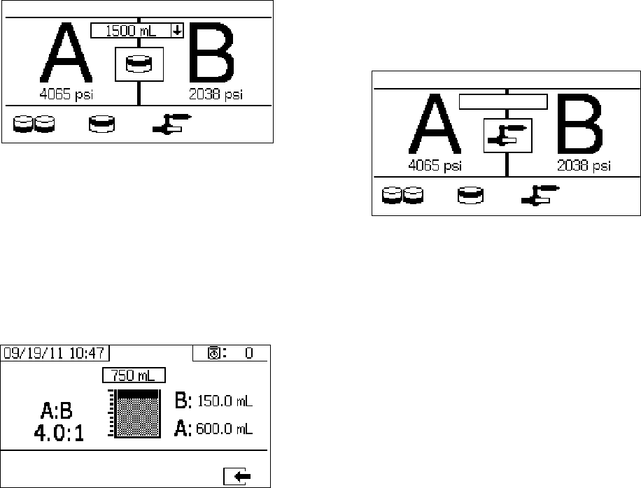
Appendix A
72 312359J
Batch Dispense Test
This screen enables users to dispense a selected total
volume of material on ratio. For example, 1000 ml at 4:1
= 800 ml of A + 200 ml of B. The total batch volume can
be selected from the drop down menu.
When the pump is active it flashes in black on the
screen. When the pump completes dispensing it dis-
plays in gray on the screen
Confirm Batch Dispense Test
This screen displays when the batch dispense test com-
pletes without error. This screen displays the selected
ratio between the pumps and the volume of material dis-
pensed from each pump. The gray at the bottom of the
beaker represents the volume of material dispensed by
pump A. The black at the top of the beaker represents
the volume of material dispensed by pump B.
Down Stream Valve Leak Test
This screen enables users to test for closed or worn
valves down stream of the A and B dosing control
valves. It can be used to test the mix manifold shut-
off/check valves or any remote circulation valves.
While running the test, if there is continuous pump
movement on the A or B side, an error will be issued.
The error indicates a leak in the valve.
There is no confirmation screen for this test. However, if
the down stream valve leak test fails, an warning is
issued to indicate the cause of the failure.
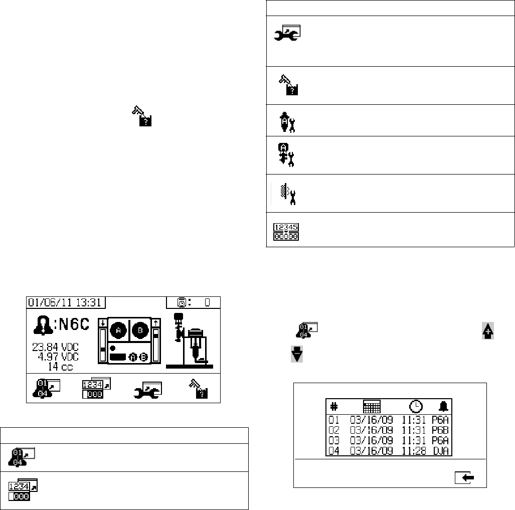
Appendix A
312359J 73
Alarm Control Screens
The Alarm control screens enable users to view alarm
diagnostic information, alarm logs, and pump batch and
grand totals. These screens also enable users to view
maintenance information for pump and check valves,
including the maintenance schedule.
NOTE:
If the potlife timer is enabled, displays.
Alarm
The Alarm screen displays the specific alarm code.
There are two levels of error codes: alarms and adviso-
ries. A solid bell icon with an exclamation point and
three audible alerts indicate a alarm. And an outlined
hollow bell icon and a single audible alert indicate an
advisory.
Additionally, this screen displays the location of the error
with the top view and side view of the system. Refer to
the following table and subsections for more details. Alarm Log
View details regarding alarms received, including the
date, time, and alarm code for the last 16 alarms. Up to
four pages of alarms are available.
Press to access the alarm log. The press
and to scroll through each page of alarms.
Icon Function
Go to Alarm log. Use up and down arrows
to scroll through list of the past 16 errors.
Go to totalizer screen. Allows users to view
the grand and batch totals for each pump
and both pumps combined.
Icon Function
Go to maintenance screen. Allows user to
view maintenance information but not make
changes.See Maintenance Setup 2, page
67.
Flush confirm. Use when the potlife timer is
enabled. Press button to confirm flush
before a potlife advisory is issued.
Amount of material moved through pump
that will result in a maintenance warning.
Amount of material moved through dosing
valve that will result in a maintenance warn-
ing.
Number of days between maintenance
cycles that will result in a reminder advi-
sory.
Clear batch totalizers or maintenance
counters.
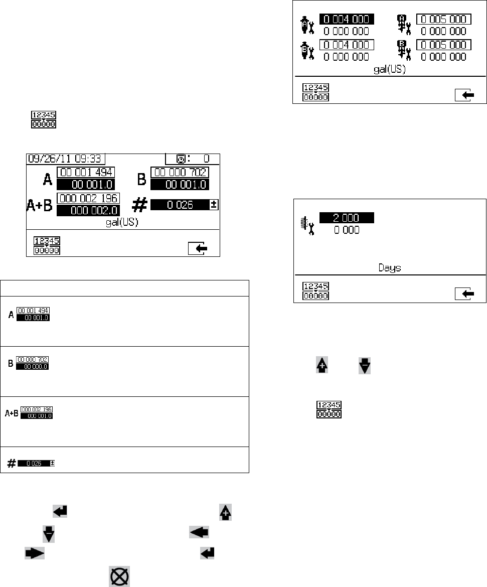
Appendix A
74 312359J
Totalizers and Job Number
View the grand and batch totals for each pump and both
pumps combined. The units of measurement are dis-
played on the bottom of the screen and displayed in the
units of measurement selected during setup.
Grand total is the amount of material the system has
dispensed during its lifetime. Batch total is the amount of
material dispensed since the last user reset.
A job number can be entered to identify the batch total.
Clear Batch Totalizer
To clear the batch totalizer values for A, B, and A+B,
press to set all values to zero.
Change Job Number
1. Press to highlight the first digit. Press
and to change the number and and
to move to the next digit. Press to
save the number or to cancel.
Maintenance 1 Screen
View setpoints for the amount of material that needs to
move through both pumps and dosing valves that will
result in a maintenance warning.
Maintenance 2 Screen
View number of days between changing the main
incoming air filter before a reminder advisory is issued.
Reset Maintenance Counter
1. Press and to scroll through and select the
maintenance field to reset.
2. Press to reset the maintenance counter to
zero.
Icon Function
Displays batch total and grand total for
pump A. The grand total is displayed at
the top, and the batch total is displayed at
the bottom.
Displays batch total and grand total for
pump B. The grand total is displayed at
the top, and the batch total is displayed at
the bottom.
Displays batch total and grand total for
both pumps combined. The grand total is
displayed at the top, and the batch total is
displayed at the bottom.
Displays job number for each spray
period.
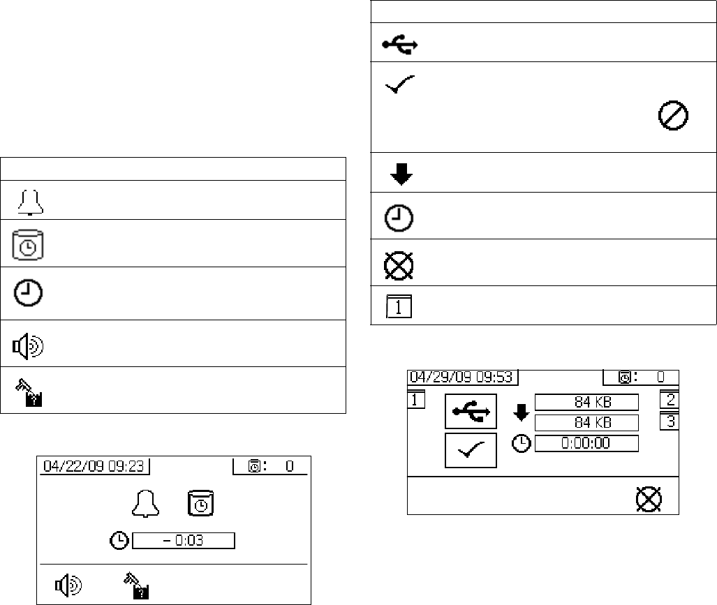
Appendix A
312359J 75
Auto Display Screens
Potlife Screen
The potlife screen automatically displays when a potlife
advisory occurs. The screen automatically closes when
the advisory end or the user presses the flush confirm
button. Refer to the following table for more details.
USB Screen
The USB screen automatically displays and the selected
log(s) automatically starts downloading when the USB
flash drive is inserted into the control box.
NOTE:
Inserting the USB flash drive while the sprayer is run-
ning automatically stops sprayer operation. Removing
the USB flash drive automatically closes the USB
screen.
The log selected for current download is displayed in the
single box next to the USB icon. The other available logs
are displayed in the boxes on the right side of the
screen. Refer to the following table for more details.
Recommended USB Flash Drives
It is recommended that users use the USB flash drive
(16A004) included with the XM sprayer for data down-
load. However, the following USB flash drives can also
be used, but are not available through Graco.
•Crucial Gizmo!
™ 4GB USB flash drive (model
JDO4GB-730) or 8GB USB flash drive (model
7DOD8GB-730)
• Transcend JetFlash® V30 4GB USB flash drive
(model TS4GJFV30)
• Transcend JetFlash® 300 4GB USB flash drive
(model TS4GJF300)
• Corsair Flash Voyager® 8GB USB flash drive
(model CMFUSB2.0-8GB)
Icon Function
Advisory has been issued.
Potlife timer is enabled.
Time after potlife expires. Starts at 0.00
and counts down in negative one minute
intervals.
Press to mute advisory buzzer.
Press to confirm that mixed hose has been
flushed. Resets potlife timer.
Icon Function
Flashes while data download is in process.
Check mark appears after download com-
pletes. Indicates download was successful.
If download was not successful,
appears.
Displays total memory to download and
remaining memory left to download.
Displays time remaining for log download to
complete.
Press to cancel download. If download is
cancelled, remove USB flash drive.
Indicates which log(s) is being down-
loaded.
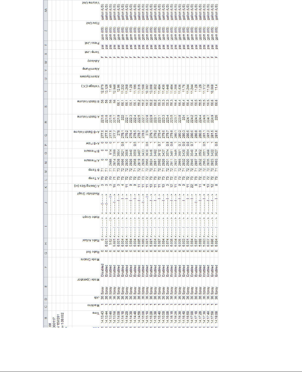
Appendix A
76 312359J
FIG. 8: Example Spray Log
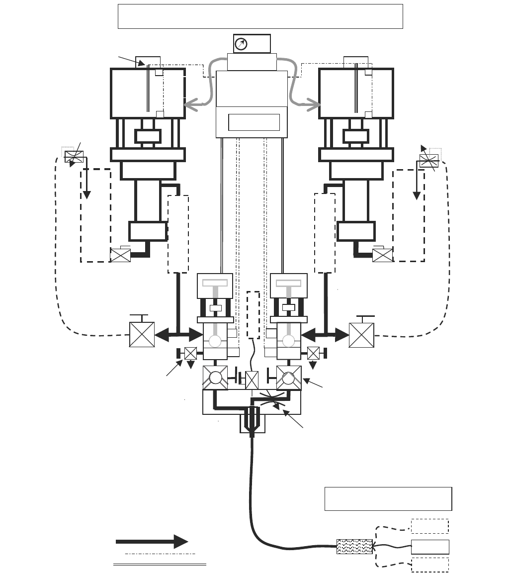
Appendix B
312359J 77
Appendix B
Metering Diagrams
Metering Diagram without Remote Mix Manifold
N
XT
6500
Air
Motor
250 HF or
180 HP
A
N
XT
6500
Air
Motor
220 HF or
145 HP
B
psi
Sample
& Test
Valves
Control
Valves
Mix Manifold
Shut-off &
Check Valves
Mix
Manifold
Integration
Hose
3/8 x 25 ft
minimum
XM Metering Diagram
Air
Re
g
Circulation
Shut/Check
Controls
Linear
Transducers
Reed
S
witches
Double
Motor Pilots
Fluid Line
Control cable
Air Signal
rtd
rtd
Recirculation
Back P ssure re
Control
Settable ‘B’
Balancing
Restriction
H
O
P
P
E
R
H
O
P
P
E
R
H
E
A
T
E
R
H
E
A
T
E
R
Gravity Feed
Or
Pump Feed
psi
F
L
U
S
H
Whi
p
Hose
N
ote: Additional guns may only be added
after the integration hose and mixer
Mixers S
p
ra
y
Gun
S
p
ra
y
Gun 2
S
p
ra
y
Gun 3
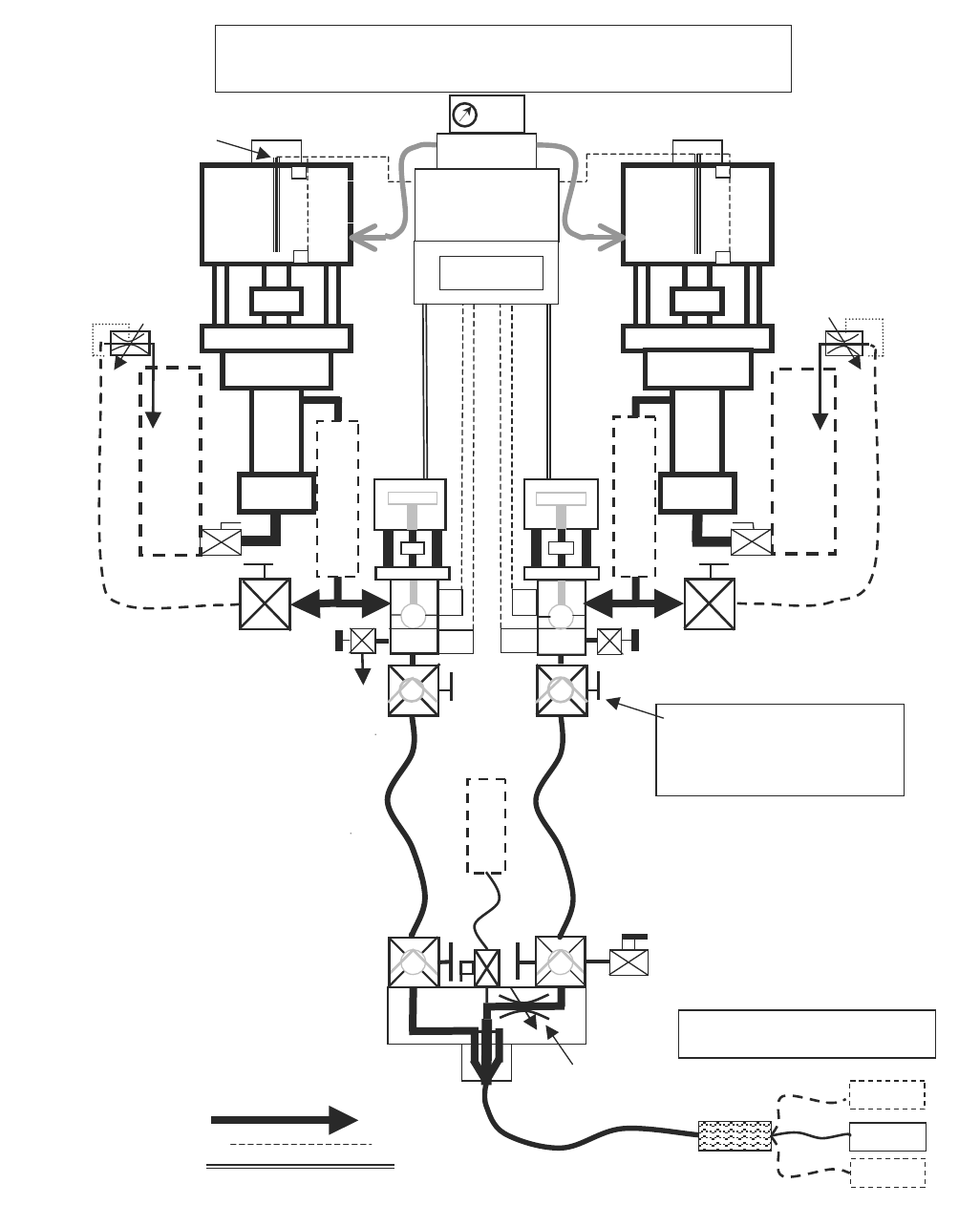
Appendix B
78 312359J
Metering Diagram with Remote Mix Manifold
N
XT
6500
Air
Motor
A
N
XT
6500
Air
Motor
B
psi
Sample
& Test
Valves
Control
Valves
Mix Manifiold
XM Metering Diagram with
Remote Mix Manifold
Circulation On / Off
Controls
Linear
Transducers
Reed
S
witches
Fluid Line
Control cable
Air Signal
rtd
rtd
Recirculation
Back Pr ssure e
Control
Settable ‘B’
Balancing
Restriction
H
O
P
P
E
R
H
O
P
P
E
R
psi
Gravity Feed
or Pump Feed
H
E
A
T
E
R
H
E
A
T
E
R
These hose isolation check valves must
be added when mix manifold is remote.
This insures that pressure transducers
read pump output and cavitation, and
not
j
ust dam
p
ened hose
p
ressure.
Remote
Shut-off &
Check Valves
Mixers S
p
ra
y
Gun
S
p
ra
y
Gun 2
S
p
ra
y
Gun 3
N
ote: Additional guns may only be added
after the integration hose and mixer
Integration Hose
3/8 x 25 ft minimum
F
L
U
S
H
Shut-off &
Hose Isolation
Check Valves
Double
Motor Pilot
Air
Re
g
250 HF or
180 HP
220 HF or
145 HP

Appendix C
312359J 79
Appendix C
Power Cord Guidelines
Use the guidelines listed in the following table to determine the power cord needed for your specific system.
◆ Wired by user if ordered. Cord size determined by user.
❄Full load amperes with all components operating at maximum capabilities. Fuse requirements for various flow
rates and heater temperature settings may be less.
XM_A (00, 11, 13,
21, 23, 30-32)
XM_A (14-19,
24-29) XM_B (all) XM_C (all)
XM_D (00, 11, 13,
21, 23, 30-32)
XM_D (17, 19, 27,
29) XM_E (all)
Power Supply wall wall wall; junction box wall alternator alternator alternator
Viscon HP Fluid
Heaters
N/A N/A 2 heaters 2 heaters N/A N/A 2 heaters
Configuration Options:
Controls 1 A, 120 Vac 1 A, 120/240 Vac 1 A, 240 Vac 1 A, 240 Vac N/A N/A N/A
Viscon HP (2)
N/A N/A 32 A at
240 Vac,
1 PH
32 A at
240 Vac,
1 PH
N/A N/A 32 A at 240 V,
1 PH (wired by
user with
explosion proof
methods)
Hopper
Immersion
Heaters (2)
N/A 13 A at 240 V,
1 PH
13 A at 240 V,
1 PH
13 A at 240 V,
1 PH
N/A N/A N/A
Viscon HP
with Heat
Circulation (1)
N/A
16 A at 240 V,
1 PH◆
or
15 A at 240 V,
1 PH◆
16 A at 240 V,
1 PH
or
15 A at 240 V,
1 PH
16 A at 240 V,
1 PH ◆
or
15 A at 240 V,
1 PH ◆
N/A 16 A at 240 V,
1 PH (wired by
user with
explosion proof
methods)
16 A at 240 V,
1 PH (wired by
user with
explosion proof
methods)
Electric Hose
Control (1)
N/A N/A N/A N/A
❄ Full Load Peak
Amperes at 240 V,
1 Phase
1 A 30 A 62 A 62 A 0 A
(air only)
16 A 48 A
Cord Specification AWG (mm2) at:
240 V, 1 PH
N/A ◆
4 (21.2)
2 wire + ground
◆N/A N/A N/A
240 V, 3 PH 6 (13.3)
3 wire + ground
380 V, 3 PH 6 (13.3)
4 wire + ground
Table 3: Power Cord Guidelines
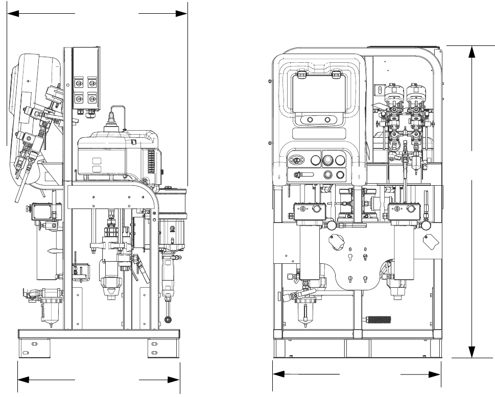
Dimensions
80 312359J
Dimensions
System Dimensions without Hoppers
70.0 in.
(1788.0 mm)
38.0 in.
(965.2 mm)
36.0 in.
(914.4 mm)
39.5 in.
(1003.3 mm)
ti21282a
Dimensions
312359J 81
System Dimensions with Hoppers
72.5 in.
(1841.5 mm)
43.1 in.
(1094.7 mm)
98.6 in.
(2504.4 mm)
Two 20-Gallon Hoppers
Side Mounted
Two 20-Gallon Hoppers
Rear Mounted
(Top View)
54.0 in.
(1371.6 mm) 49.7 in.
(1262.4 mm)
62.8 in.
(1595.1 mm)
38.4 in.
(975.4 mm) 56.2 in.
(1427.5 mm)
ti21283a
Dimensions
82 312359J
System Dimensions with Hoppers
One 20-Gallon Hopper and One 7-Gallon Hopper
70.0 in.
(1788.0 mm)
33.4 in.
(848.4 mm)
79.1 in.
(2009.1 mm)
43.1 in.
(1094.7 mm)
72.5 in.
(1841.5 mm)
33.4 in.
(848.4 mm)
59.7 in.
(1516.4 mm)
70.0 in.
(1788.0 mm)
Two 7-Gallon Hoppers
ti21284a
Pump Performance Charts
312359J 83
Pump Performance Charts
Calculate Fluid Outlet Pressure
To calculate fluid outlet pressure (MPa/bar/psi) at a specific
fluid flow (lpm/gpm) and operating air pressure (MPa/bar/psi),
use the following instructions and pump data charts.
1. Locate desired flow along bottom of chart.
2. Follow vertical line up to intersection with selected fluid
outlet pressure curve. Follow left to scale to read fluid out-
let pressure.
Calculate Pump Air Consumption
To calculate pump air consumption (m3/min or scfm) at a spe-
cific fluid flow (lpm/gpm) and air pressure (MPa/bar/psi), use
the following instructions and pump data charts.
1. Locate desired flow along bottom of chart.
2. Follow vertical line up to intersection with selected air con-
sumption curve. Follow right to scale to read air consump-
tion.
NOTE: Ratio setpoint has no significant effect on curves in either performance chart.
Air consumption includes turbine alternator; it does not include feed pumps or agitators.
XM50 Fluid Performance and Air Consumption
1000
140
100
3000
5000
180
7000
60
20
1.0 2.0 3.0
0.0
Fluid Pressure in psi (MPa, bar)
Air Consumption in SCFM (m3/min)
Fluid Flow in gpm (lpm)
(3.8) (7.6) (11.4)
(7.0, 70)
(5.0)
(3.9)
(2.8)
(1.7)
(0.6)
(49.0, 490)
(35.0, 350)
(21.0, 210)
XM70 Fluid Performance and Air Consumption
1000
140
100
3000
5000
180
7000
60
20
1.0 2.0 3.0
0.0
Fluid Pressure in psi (MPa, bar)
Fluid Flow in gpm (lpm)
(3.8) (7.6) (11.4)
(7.0, 70)
(5.0)
(3.9)
(2.8)
(1.7)
(0.6)
(49.0, 490)
(35.0, 350)
(21.0, 210)
A
A
AA
B
B
B
B
KEY:
A = 100 psi (0.7 MPa, 7 bar)
B = 70 psi (0.48 MPa, 4.8 bar)
KEY:
A = 90 psi (0.62 MPa, 6.2 bar)
B = 70 psi (0.48 MPa, 4.8 bar)
Air Consumption in SCFM (m3/min)
Technical Data
84 312359J
Technical Data
* Minimum flow rate is dependent on material being sprayed and mixing capability. Test your material specific to flow rate.
Mixed ratio range. . . . . . . . . . . . . . . . . . . . . . . . . . . . . . . . . . 1:1-10:1 (in 0.1 increments)
Ratio tolerance range (before alarm). . . . . . . . . . . . . . . . . . . +/- 5%
Flow rates
Minimum . . . . . . . . . . . . . . . . . . . . . . . . . . . . . . . . . . . . .
Maximum . . . . . . . . . . . . . . . . . . . . . . . . . . . . . . . . . . . .
1 qt./min. (0.95 liter/min.)*
3 gal./min/ (11.4 liter/min.)
Fluid viscosity range . . . . . . . . . . . . . . . . . . . . . . . . . . . . . . . 200-20,000 cps (heavier viscosities can be mixed using heat,
circulation, and/or pressure feeding)
Fluid filtration . . . . . . . . . . . . . . . . . . . . . . . . . . . . . . . . . . . . . 60 mesh, (238 micron) standard on pump outlets (filter
assembly not included on some models); alternative 30
mesh screens included
Air inlet . . . . . . . . . . . . . . . . . . . . . . . . . . . . . . . . . . . . . . . . . 3/4 npt(f)
Fluid inlets without feed kits. . . . . . . . . . . . . . . . . . . . . . . . . . 1 1/4 npt(m)
Maximum fluid working pressure of mixed material
50:1. . . . . . . . . . . . . . . . . . . . . . . . . . . . . . . . . . . . . . . . .
70:1. . . . . . . . . . . . . . . . . . . . . . . . . . . . . . . . . . . . . . . . .
5200 psi (35.8 MPa, 358 bar)
6300 psi (43.5 MPa, 435 bar)
Maximum fluid temperature . . . . . . . . . . . . . . . . . . . . . . . . . 160° F (71° C)
Air supply pressure range . . . . . . . . . . . . . . . . . . . . . . . . . . . 50-150 psi (0.35-1.0 MPa, 3.5-10.3 bar)
Maximum pump air set pressure
50:1. . . . . . . . . . . . . . . . . . . . . . . . . . . . . . . . . . . . . . . . .
70:1. . . . . . . . . . . . . . . . . . . . . . . . . . . . . . . . . . . . . . . . .
100 psi (0.70 MPa, 7.0 bar)
90 psi (0.62 MPa, 6.2 bar)
Maximum pump inlet fluid feed pressure. . . . . . . . . . . . . . . . 250 psi (1.7 MPa, 17 bar)
Maximum air consumption at 100 psi (0.7 MPa, 7.0 bar)
in scfm (m3/min.) . . . . . . . . . . . . . . . . . . . . . . . . . . . . . . . . . . 70 scfm per gpm (1.96 m3/min. per lpm)
Air filtration. . . . . . . . . . . . . . . . . . . . . . . . . . . . . . . . . . . . . . . 40 micron main filter, 5 micron control air filter; see Pump
Performance Charts, page 83
Ambient temperature range
Operating . . . . . . . . . . . . . . . . . . . . . . . . . . . . . . . . . . . .
Storage . . . . . . . . . . . . . . . . . . . . . . . . . . . . . . . . . . . . . .
32-130° F (0-54° C)
30-160° F (-1-71° C)
Environmental conditions rating . . . . . . . . . . . . . . . . . . . . . . Indoor/outdoor use
Altitude up to 4000 m
Maximum relative humidity to 99% up to 130° F (54° C)
Pollution degree (11)
Installation category (2)
Sound pressure . . . . . . . . . . . . . . . . . . . . . . . . . . . . . . . . . . . 86 dBA at 100 psi (0.7 MPa, 7 bar)
Sound power . . . . . . . . . . . . . . . . . . . . . . . . . . . . . . . . . . . . . 98 dBA at 100 psi (0.7 MPa, 7 bar)
Wetted parts
Suction tubes . . . . . . . . . . . . . . . . . . . . . . . . . . . . . . . . .
Flush pump. . . . . . . . . . . . . . . . . . . . . . . . . . . . . . . . . . .
Hoses . . . . . . . . . . . . . . . . . . . . . . . . . . . . . . . . . . . . . . .
Pumps (A and B) . . . . . . . . . . . . . . . . . . . . . . . . . . . . . .
Metering valves. . . . . . . . . . . . . . . . . . . . . . . . . . . . . . . .
Manifold . . . . . . . . . . . . . . . . . . . . . . . . . . . . . . . . . . . . .
Mixer . . . . . . . . . . . . . . . . . . . . . . . . . . . . . . . . . . . . . . . .
Spray gun . . . . . . . . . . . . . . . . . . . . . . . . . . . . . . . . . . . .
aluminum
carbide, PTFE, stainless steel, UHMWPE
nylon
carbon steel, alloy steel, 303, 440, 17-ph grades stainless
steel, zinc and nickel plating, ductile iron, tungsten carbide,
PTFE
carbon steel, nickel plating, carbide, polyethylene, leather
carbon steel, nickel plating, carbide, 302 stainless steel,
PTFE, UHMWPE
stainless steel housing with acetal elements
Refer to spray gun manual
Dimensions . . . . . . . . . . . . . . . . . . . . . . . . . . . . . . . . . . . . . . See Dimensions, page 80
Weight . . . . . . . . . . . . . . . . . . . . . . . . . . . . . . . . . . . . . . . . . . Base sprayer (XM1A00 and XM5A00 models)
742 lbs (336.87 kg)
(Add component weights to base sprayer weight for your
specific model weight.)

Technical Data
312359J 85

All written and visual data contained in this document reflects the latest product information available at the time of publication.
Graco reserves the right to make changes at any time without notice.
For patent information, see www.graco.com/patents.
Original instructions. This manual contains English. MM 312359
Graco Headquarters: Minneapolis
International Offices: Belgium, China, Japan, Korea
GRACO INC. AND SUBSIDIARIES • P.O. BOX 1441 • MINNEAPOLIS MN 55440-1441 • USA
Copyright 2009, Graco Inc. All Graco manufacturing locations are registered to ISO 9001.
www.graco.com
Revised March 2013
Graco Standard Warranty
Graco warrants all equipment referenced in this document which is manufactured by Graco and bearing its name to be free from defects in
material and workmanship on the date of sale to the original purchaser for use. With the exception of any special, extended, or limited warranty
published by Graco, Graco will, for a period of twelve months from the date of sale, repair or replace any part of the equipment determined by
Graco to be defective. This warranty applies only when the equipment is installed, operated and maintained in accordance with Graco’s written
recommendations.
This warranty does not cover, and Graco shall not be liable for general wear and tear, or any malfunction, damage or wear caused by faulty
installation, misapplication, abrasion, corrosion, inadequate or improper maintenance, negligence, accident, tampering, or substitution of
non-Graco component parts. Nor shall Graco be liable for malfunction, damage or wear caused by the incompatibility of Graco equipment with
structures, accessories, equipment or materials not supplied by Graco, or the improper design, manufacture, installation, operation or
maintenance of structures, accessories, equipment or materials not supplied by Graco.
This warranty is conditioned upon the prepaid return of the equipment claimed to be defective to an authorized Graco distributor for verification of
the claimed defect. If the claimed defect is verified, Graco will repair or replace free of charge any defective parts. The equipment will be returned
to the original purchaser transportation prepaid. If inspection of the equipment does not disclose any defect in material or workmanship, repairs will
be made at a reasonable charge, which charges may include the costs of parts, labor, and transportation.
THIS WARRANTY IS EXCLUSIVE, AND IS IN LIEU OF ANY OTHER WARRANTIES, EXPRESS OR IMPLIED, INCLUDING BUT NOT LIMITED
TO WARRANTY OF MERCHANTABILITY OR WARRANTY OF FITNESS FOR A PARTICULAR PURPOSE.
Graco’s sole obligation and buyer’s sole remedy for any breach of warranty shall be as set forth above. The buyer agrees that no other remedy
(including, but not limited to, incidental or consequential damages for lost profits, lost sales, injury to person or property, or any other incidental or
consequential loss) shall be available. Any action for breach of warranty must be brought within two (2) years of the date of sale.
GRACO MAKES NO WARRANTY, AND DISCLAIMS ALL IMPLIED WARRANTIES OF MERCHANTABILITY AND FITNESS FOR A
PARTICULAR PURPOSE, IN CONNECTION WITH ACCESSORIES, EQUIPMENT, MATERIALS OR COMPONENTS SOLD BUT NOT
MANUFACTURED BY GRACO. These items sold, but not manufactured by Graco (such as electric motors, switches, hose, etc.), are subject to
the warranty, if any, of their manufacturer. Graco will provide purchaser with reasonable assistance in making any claim for breach of these
warranties.
In no event will Graco be liable for indirect, incidental, special or consequential damages resulting from Graco supplying equipment hereunder, or
the furnishing, performance, or use of any products or other goods sold hereto, whether due to a breach of contract, breach of warranty, the
negligence of Graco, or otherwise.
FOR GRACO CANADA CUSTOMERS
The Parties acknowledge that they have required that the present document, as well as all documents, notices and legal proceedings entered into,
given or instituted pursuant hereto or relating directly or indirectly hereto, be drawn up in English. Les parties reconnaissent avoir convenu que la
rédaction du présente document sera en Anglais, ainsi que tous documents, avis et procédures judiciaires exécutés, donnés ou intentés, à la suite
de ou en rapport, directement ou indirectement, avec les procédures concernées.
Graco Information
For the latest information about Graco products, visit www.graco.com.
TO PLACE AN ORDER, contact your Graco distributor or call to identify the nearest distributor.
Phone: 612-623-6921 or Toll Free: 1-800-328-0211 Fax: 612-378-3505
