Graco 312759R Pr70 And Pr70V With Advanced Display Module Users Manual Module, Operation Maintenance, English
312759R to the manual 1566a05f-b941-456c-af63-0d5de07824da
2015-04-02
: Graco Graco-312759R-Pr70-And-Pr70V-With-Advanced-Display-Module-Users-Manual-685887 graco-312759r-pr70-and-pr70v-with-advanced-display-module-users-manual-685887 graco pdf
Open the PDF directly: View PDF ![]() .
.
Page Count: 82
- Related Manuals
- Product Configurator
- Warnings
- Component Identification
- Screen Navigation Diagram
- Grounding
- Installation
- Startup
- Setup
- Setup Screens
- Edit Settings
- Piston Position Calibration
- Prime the Dispense Head
- Phasing Adjustment
- Adjust Dispense Valve Snuff Back
- Adjust Open Dispense Valve (ODV) Timing
- Calibrate Dispense Weight Ratio (PR70v only)
- Shot Calibration
- Flow Meter Calibration
- Dispense Verification
- External Control Interface Setup
- Operation
- USB Data
- Pressure Relief Procedure
- Shutdown
- Maintenance
- Troubleshooting
- Kits
- Dimensions
- Technical Data
- Graco Standard Warranty
- Graco Information
312759R
EN
Operation - Maintenance
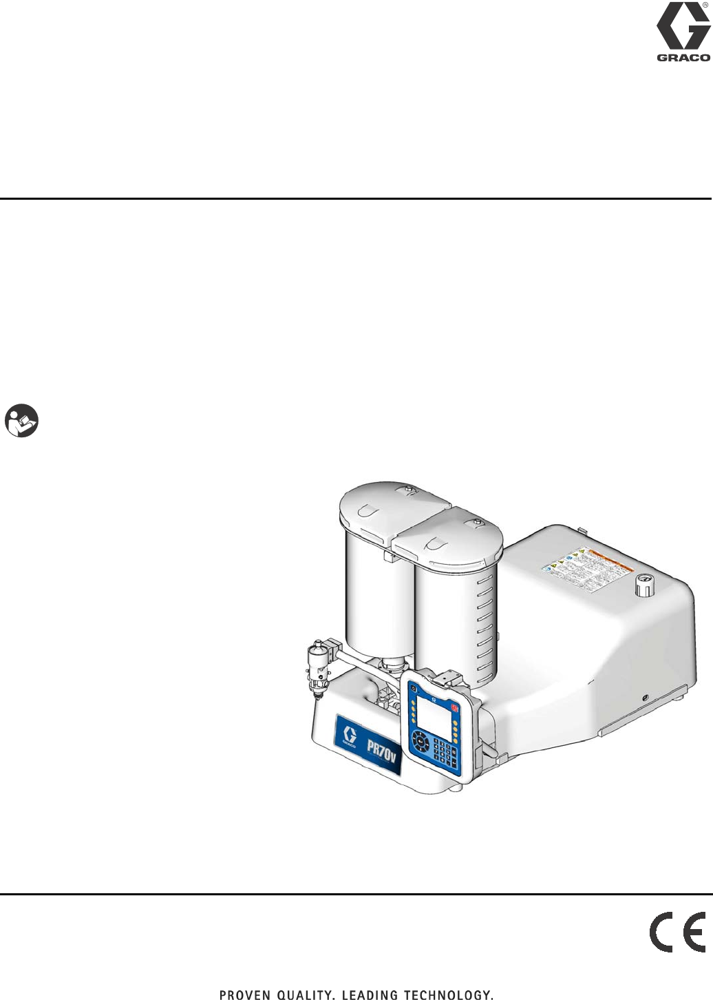
PR70™ and PR70v™
with Advanced Display Module
Fixed or variable ratio systems. For accurate metering, mixing, and dispensing of
two-component materials. For professional use only.
Not approved for use in European explosive atmosphere locations.
3000 psi (21 MPa, 207 bar) Maximum Working Pressure
100 psi (0.7 MPa, 7 bar) Maximum Air Inlet Pressure
Important Safety Instructions
Read all warnings and instructions in all sup-
plied manuals. Save these instructions.
PR70v Shown with Advanced Display Module
ti12385b
2312759R
Contents
Related Manuals . . . . . . . . . . . . . . . . . . . . . . . . . . . 3
Product Configurator . . . . . . . . . . . . . . . . . . . . . . . 4
Warnings . . . . . . . . . . . . . . . . . . . . . . . . . . . . . . . . 11
Component Identification . . . . . . . . . . . . . . . . . . . 13
Advanced Display Module (ADM) . . . . . . . . . . . 15
Screen Navigation Diagram . . . . . . . . . . . . . . . . . 16
Grounding . . . . . . . . . . . . . . . . . . . . . . . . . . . . . . . 17
Installation . . . . . . . . . . . . . . . . . . . . . . . . . . . . . . . 17
Machine Installation . . . . . . . . . . . . . . . . . . . . . 17
Tank Refill Kit 256577 Installation . . . . . . . . . . . 19
Startup . . . . . . . . . . . . . . . . . . . . . . . . . . . . . . . . . . 21
Setup . . . . . . . . . . . . . . . . . . . . . . . . . . . . . . . . . . . . 22
Setup Screens . . . . . . . . . . . . . . . . . . . . . . . . . 22
Edit Settings . . . . . . . . . . . . . . . . . . . . . . . . . . . 37
Piston Position Calibration . . . . . . . . . . . . . . . . 37
Prime the Dispense Head . . . . . . . . . . . . . . . . . 39
Phasing Adjustment . . . . . . . . . . . . . . . . . . . . . 40
Adjust Dispense Valve Snuff Back . . . . . . . . . . 42
Adjust Open Dispense Valve (ODV) Timing . . . 43
Calibrate Dispense Weight Ratio (PR70v only) 44
Shot Calibration . . . . . . . . . . . . . . . . . . . . . . . . . 47
Flow Meter Calibration . . . . . . . . . . . . . . . . . . . 48
Dispense Verification . . . . . . . . . . . . . . . . . . . . . 48
External Control Interface Setup . . . . . . . . . . . . 49
Operation . . . . . . . . . . . . . . . . . . . . . . . . . . . . . . . . 53
Operation Screens . . . . . . . . . . . . . . . . . . . . . . 53
Auto-Refill . . . . . . . . . . . . . . . . . . . . . . . . . . . . . 62
Temperature Control . . . . . . . . . . . . . . . . . . . . . 63
Purge Timer . . . . . . . . . . . . . . . . . . . . . . . . . . . 63
USB Data . . . . . . . . . . . . . . . . . . . . . . . . . . . . . . . . 64
USB Logs . . . . . . . . . . . . . . . . . . . . . . . . . . . . . 64
Download Procedure . . . . . . . . . . . . . . . . . . . . . 64
Pressure Relief
Procedure . . . . . . . . . . . . . . . . . . . . . . . . . . . . . 65
Shutdown . . . . . . . . . . . . . . . . . . . . . . . . . . . . . . . . 65
Maintenance . . . . . . . . . . . . . . . . . . . . . . . . . . . . . . 66
Schedule . . . . . . . . . . . . . . . . . . . . . . . . . . . . . . 66
Clean the Pump Shafts . . . . . . . . . . . . . . . . . . . 66
Disassemble and Clean the Dispense Head . . . 66
Flush Pneumatic Air Motor 82/0216/11 . . . . . . . 67
Lubricate Pneumatic Air Motor . . . . . . . . . . . . . 67
Lubricate Gear Box of Pneumatic Air Motor
01/0368-1/11 . . . . . . . . . . . . . . . . . . . . . . . . 67
Install Upgrade Token . . . . . . . . . . . . . . . . . . . . 68
Troubleshooting . . . . . . . . . . . . . . . . . . . . . . . . . . . 69
Error Codes . . . . . . . . . . . . . . . . . . . . . . . . . . . 71
Kits . . . . . . . . . . . . . . . . . . . . . . . . . . . . . . . . . . . . . 76
Dimensions . . . . . . . . . . . . . . . . . . . . . . . . . . . . . . . 78
Machine with On-Board Tanks . . . . . . . . . . . . . . 78
Machine with Off-Board Tanks . . . . . . . . . . . . . . 79
Technical Data . . . . . . . . . . . . . . . . . . . . . . . . . . . . 80
Graco Standard Warranty . . . . . . . . . . . . . . . . . . . 82
Graco Information . . . . . . . . . . . . . . . . . . . . . . . . . 82

Related Manuals
312759R 3
Related Manuals
PR70 and PR70v Operation and Parts Manuals
Part Description
3A0429 PR70 with Standard Display Module Operation and
Maintenance Manual
312759 PR70 and PR70v with Advanced Display Module
Operation and Maintenance Manual
312760 PR70 and PR70v Repair and Parts Manual
312394 PR70 and PR70v Feed Systems Manual
312761 PR70v Integrated Heat Instructions - Parts Manual
MD2 Dispense Valve Manual
Part Description
312185 MD2 Dispense Valve Instructions and Parts Manual
Product Configurator
4312759R
Product Configurator
An example of the product configurator would be the following configurator code.
The following part number fields apply for the PR70 and PR70v part numbering configurator fields. Shaded items
listed in the configurator table below are “Super Standard” items that are typically stocked and provide the best deliv-
ery dates.
PR7F------------------
Code: A B-C D-E F G-H I-J K L M N O P Q R S T U V
Air Motor
High Volume Side Piston
Low Volume Side Piston
Controls
High Volume Side Hose
Low Volume Side Hose
Dispense Valve
Mixer
Applicator Mounting
Power Cord
Flow Monitoring
High Volume Side Tank
High Volume Side Tank Cover
Low Volume Side Tank
Low Volume Side Tank Cover
Tank Level Sensors
Heat Zone Controller
Off-Board Tank Stand
PR7F-J-A5-A5-E-A6-A6-3-1-2-A-N-3-N-H-N-6-N-N
Code: A B-C D-E F G-H I-J K L M N O P Q R S T U V
Air Motor
High Volume Side Piston
Low Volume Side Piston
Controls
High Volume Side Hose
Low Volume Side Hose
Dispense Valve
Mixer
Applicator Mounting
Power Cord
Flow Monitoring
High Volume Side Tank
High Volume Side Tank Cover
Low Volume Side Tank
Low Volume Side Tank Cover
Tank Level Sensors
Heat Zone Controller
Off-Board Tank Stand
Code A Part Air Motor
A LC0262 PR70 with 3.0 in. (4.56 mm) Air Motor
B LC0264 PR70 with 4.5 in. (10.26 mm) Air Motor
C LC0263 PR70 with 3.0 in. (4.56 mm) Air Motor
and Hydracheck
D LC0265 PR70 with 4.5 in. (10.26 mm) Air Motor
and Hydracheck
F LC0242 PR70v with 3.0 in. (4.56 mm) Air Motor
G LC0244 PR70v with 4.5 in. (10.26 mm) Air
Motor
H LC0243 PR70v with 3.0 in. (4.56 mm) Air Motor
and Hydracheck
J LC0245 PR70v with 4.5 in. (10.26 mm) Air
Motor and Hydracheck
Code B Part
High Volume Side Piston and
Metering Tube Material
A LC1___ Nylon Piston, Stainless Steel Metering
Tube (last three digits of part number
is the mm2 piston size)
B LC2___ UHMWPE Piston, Stainless Steel
Metering Tube (last three digits of part
number is the mm2 piston size)
C LC3___ UHMWPE Piston, Ceramic Metering
Tube (last three digits of part number
is the mm2 piston size)
Code C Part High Volume Piston Size (mm2)
180, Available in Nylon Only
2 100, Available in Nylon Only
3120, Available in Nylon Only

Product Configurator
312759R 5
4 140, Available in Nylon Only
5160
6 180
7 200
8 220
9240
A 260
B 280
C 300
F320
G 360
H 400
J 440
L480
M 520
R 560
S 600
T640
U 720
W 800
X 880
Y960
Z Custom High Volume side, consult fac-
tory (stainless steel only)
Code D Part
Low Volume Side Piston and
Metering Tube Material
A LC1___ Nylon Piston, Stainless Steel Metering
Tube (last three digits of part number
is the mm2 piston size)
B LC2___ UHMWPE Piston, Stainless Steel
Metering Tube (last three digits of part
number is the mm2 piston size)
C LC3___ UHMWPE Piston, Ceramic Metering
Tube (last three digits of part number
is the mm2 piston size)
Code E Part Low Volume Side Piston Size (mm2)
180, Available in Nylon Only
2 100, Available in Nylon Only
3120, Available in Nylon Only
4 140, Available in Nylon Only
5160
6 180
7 200
8 220
9240
A 260
B 280
C 300
F320
G 360
H 400
J440
L480
M520
R560
S600
T640
U720
W800
X880
Y960
Z Custom Low Volume side, consult fac-
tory (stainless steel only)
Code F Part Controls
B LC0272 Standard Display Module with 1 Fluid
Control Module
D LC0274 Advanced Display Module with 1 Fluid
Control Module
E LC0275 Advanced Display Module with 2 Fluid
Control Modules
Codes
G-H,
I-J Part
High Volume Hose /
Low Volume Hose
A1 LC0801 3/16 in. (4.8 mm) - 2.5 ft (0.6 m)
A2 LC0802 3/16 in. (4.8 mm) - 10 ft (3.0 m)
A3 LC0803 3/16 in. (4.8 mm) - 15 ft (4.6 m)
A4 LC0804 1/4 in. (6.5 mm) - 2.5 ft (0.6 m)
A5 LC0805 1/4 in. (6.5 mm) - 10 ft (3.0 m)
A6 LC0806 1/4 in. (6.5 mm) - 15 ft (4.6 m)
A7 LC0807 3/8 in. (9.5 mm) - 2.5 ft (0.6 m)
A8 LC0808 3/8 in. (9.5 mm) - 10 ft (3.0 m)
A9 LC0809 3/8 in. (9.5 mm) - 15 ft (4.6 m)
AA LC0810 1/2 in. (13 mm) - 2.5 ft (0.6 m)
AB LC0811 1/2 in. (13 mm) - 10 ft (3.0 m)
AC LC0812 1/2 in. (13 mm) - 15 ft (4.6 m)
AG LC0813 3/4 in. (19 mm) - 10 ft (3.0 m)
AH LC0814 3/4 in. (19 mm) - 15 ft (4.6 m)
B4 LC0881 Heated, 1/4 in. (6.5 mm) - 2.5 ft (0.6 m)
B5 LC0882 Heated, 1/4 in. (6.5 mm) - 10 ft (3.0 m)
B6 LC0883 Heated, 1/4 in. (6.5 mm) - 15 ft (4.6 m)
B7 LC0884 Heated, 3/8 in. (9.5 mm) - 2.5 ft (0.6 m)
B8 LC0885 Heated, 3/8 in. (9.5 mm) - 10 ft (3.0 m)
B9 LC0886 Heated, 3/8 in. (9.5 mm) - 15 ft (4.6 m)
BA LC0887 Heated, 1/2 in. (13 mm) - 2.5 ft (0.6 m)
BB LC0888 Heated, 1/2 in. (13 mm) - 10 ft (3.0 m)
BC LC0889 Heated, 1/2 in. (13 mm) - 15 ft (4.6 m)
BG LC0890 Heated, 3/4 in. (19 mm) - 10 ft (3.0 m)
BH LC0891 Heated, 3/4 in. (19 mm) - 15 ft (4.6 m)
C1 LC0161 Recirculating, On-Board Tanks,
3/16 in. (4.8 mm) - 2.5 ft (0.6 m)
C2 LC0162 Recirculating, On-Board Tanks,
3/16 in. (4.8 mm) - 10 ft (3.0 m)

Product Configurator
6312759R
C3 LC0163 Recirculating, On-Board Tanks,
3/16 in. (4.8 mm) - 15 ft (4.6 m)
C4 LC0164 Recirculating, On-Board Tanks,
1/4 in. (6.5 mm) - 2.5 ft (0.6 m)
C5 LC0165 Recirculating, On-Board Tanks,
1/4 in. (6.5 mm) - 10 ft (3.0 m)
C6 LC0166 Recirculating, On-Board Tanks,
1/4 in. (6.5 mm) - 15 ft (4.6 m)
C7 LC0167 Recirculating, On-Board Tanks,
3/8 in. (9.5 mm) - 2.5 ft (0.6 m)
C8 LC0168 Recirculating, On-Board Tanks,
3/8 in. (9.5 mm) - 10 ft (3.0 m)
C9 LC0169 Recirculating, On-Board Tanks,
3/8 in. (9.5 mm) - 15 ft (4.6 m)
CA LC0170 Recirculating, On-Board Tanks,
1/2 in. (13 mm) - 2.5 ft (0.6 m)
CB LC0171 Recirculating, On-Board Tanks,
1/2 in. (13 mm) - 10 ft (3.0 m)
CC LC0172 Recirculating, On-Board Tanks,
1/2 in. (13 mm) - 15 ft (4.6 m)
CD LC0173 Recirculating, On-Board Tanks,
3/4 in. (19 mm) - 10 ft (3.0 m)
CE LC0174 Recirculating, On-Board Tanks,
3/4 in. (19 mm) - 15 ft (4.6 m)
D1 LC0175 Recirculating, Off-Board Tanks,
3/16 in. (4.8 mm) - 2.5 ft (0.6 m)
D2 LC0176 Recirculating, Off-Board Tanks,
3/16 in. (4.8 mm) - 10 ft (3.0 m)
D3 LC0177 Recirculating, Off-Board Tanks,
3/16 in. (4.8 mm) - 15 ft (4.6 m)
D4 LC0178 Recirculating, Off-Board Tanks,
1/4 in. (6.5 mm) - 2.5 ft (0.6 m)
D5 LC0179 Recirculating, Off-Board Tanks,
1/4 in. (6.5 mm) - 10 ft (3.0 m)
D6 LC0180 Recirculating, Off-Board Tanks,
1/4 in. (6.5 mm) - 15 ft (4.6 m)
D7 LC0181 Recirculating, Off-Board Tanks,
3/8 in. (9.5 mm) - 2.5 ft (0.6 m)
D8 LC0182 Recirculating, Off-Board Tanks,
3/8 in. (9.5 mm) - 10 ft (3.0 m)
D9 LC0183 Recirculating, Off-Board Tanks,
3/8 in. (9.5 mm) - 15 ft (4.6 m)
DA LC0184 Recirculating, Off-Board Tanks,
1/2 in. (13 mm) - 2.5 ft (0.6 m)
DB LC0185 Recirculating, Off-Board Tanks,
1/2 in. (13 mm) - 10 ft (3.0 m)
DC LC0186 Recirculating, Off-Board Tanks,
1/2 in. (13 mm) - 15 ft (4.6 m)
DD LC0187 Recirculating, Off-Board Tanks,
3/4 in. (19 mm) - 10 ft (3.0 m)
DE LC0188 Recirculating, Off-Board Tanks,
3/4 in. (19 mm) - 15 ft (4.6 m)
E1 LC0190 Recirculating, Heated, On-Board
Tanks, 1/4 in. (6.5 mm) - 2.5 ft (0.6 m)
E2 LC0191 Recirculating, Heated, On-Board
Tanks, 1/4 in. (6.5 mm) - 10 ft (3.0 m)
E3 LC0192 Recirculating, Heated, On-Board
Tanks, 1/4 in. (6.5 mm) - 15 ft (4.6 m)
E4 LC0193 Recirculating, Heated, On-Board
Tanks, 3/8 in. (9.5 mm) - 2.5 ft (0.6 m)
E5 LC0194 Recirculating, Heated, On-Board
Tanks, 3/8 in. (9.5 mm) - 10 ft (3.0 m)
E6 LC0195 Recirculating, Heated, On-Board
Tanks, 3/8 in. (9.5 mm) - 15 ft (4.6 m)
E7 LC0196 Recirculating, Heated, On-Board
Tanks, 1/2 in. (13 mm) - 2.5 ft (0.6 m)
E8 LC0197 Recirculating, Heated, On-Board
Tanks, 1/2 in. (13 mm) - 10 ft (3.0 m)
E9 LC0198 Recirculating, Heated, On-Board
Tanks, 1/2 in. (13 mm) - 15 ft (4.6 m)
EA LC0199 Recirculating, Heated, On-Board
Tanks, 3/4 in. (19 mm) - 10 ft (3.0 m)
EB LC0200 Recirculating, Heated, On-Board
Tanks, 3/4 in. (19 mm) - 15 ft (4.6 m)
F1 LC0201 Recirculating, Heated, Off-Board
Tanks, 1/4 in. (6.5 mm) - 2.5 ft (0.6 m)
F2 LC0202 Recirculating, Heated, Off-Board
Tanks, 1/4 in. (6.5 mm) - 10 ft (3.0 m)
F3 LC0203 Recirculating, Heated, Off-Board
Tanks, 1/4 in. (6.5 mm) - 15 ft (4.6 m)
F4 LC0204 Recirculating, Heated, Off-Board
Tanks, 3/8 in. (9.5 mm) - 2.5 ft (0.6 m)
F5 LC0205 Recirculating, Heated, Off-Board
Tanks, 3/8 in. (9.5 mm) - 10 ft (3.0 m)
F6 LC0206 Recirculating, Heated, Off-Board
Tanks, 3/8 in. (9.5 mm) - 15 ft (4.6 m)
F7 LC0207 Recirculating, Heated, Off-Board
Tanks, 1/2 in. (13 mm) - 2.5 ft (0.6 m)
F8 LC0208 Recirculating, Heated, Off-Board
Tanks, 1/2 in. (13 mm) - 10 ft (3.0 m)
F9 LC0209 Recirculating, Heated, Off-Board
Tanks, 1/2 in. (13 mm) - 15 ft (4.6 m)
FA LC0210 Recirculating, Heated, Off-Board
Tanks, 3/4 in. (19 mm) - 10 ft (3.0 m)
FB LC0211 Recirculating, Heated, Off-Board
Tanks, 3/4 in. (19 mm) - 15 ft (4.6 m)
GA LC0400 High Pressure, 3/8 in. (9.5 mm) - 2.5 ft
(0.6 m)
GB LC0401 High Pressure, 3/8 in. (9.5 mm) - 10 ft
(3.0 m)
GC LC0402 High Pressure, 3/8 in. (9.5 mm) - 15 ft
(4.6 m)
GD LC0403 High Pressure, 1/2 in. (13 mm) - 2.5 ft
(0.6 m)
GE LC0404 High Pressure, 1/2 in. (13 mm) - 10 ft
(3.0 m)
GF LC0405 High Pressure, 1/2 in. (13 mm) - 15 ft
(4.6 m)

Product Configurator
312759R 7
GH LC0406 High Pressure, 3/4 in. (19 mm) - 10 ft
(3.0 m)
GJ LC0407 High Pressure, 3/4 in. (19 mm) - 15 ft
(4.6 m)
GK LC0432 High Pressure, Recirculating,
On-Board Tanks,
3/8 in. (9.5 mm) - 2.5 ft (0.6 m)
GL LC0433 High Pressure, Recirculating,
On-Board Tanks,
3/8 in. (9.5 mm) - 10 ft (3.0 m)
GM LC0434 High Pressure, Recirculating,
On-Board Tanks,
3/8 in. (9.5 mm) - 15 ft (4.6 m)
GQ LC0435 High Pressure, Recirculating,
On-Board Tanks,
1/2 in. (13 mm) - 2.5 ft (0.6 m)
GR LC0436 High Pressure, Recirculating,
On-Board Tanks,
1/2 in. (13 mm) - 10 ft (3.0 m)
GS LC0437 High Pressure, Recirculating,
On-Board Tanks,
1/2 in. (13 mm) - 15 ft (4.6 m)
GT LC0438 High Pressure, Recirculating,
On-Board Tanks,
3/4 in. (19 mm) - 10 ft (3.0 m)
GU LC0439 High Pressure, Recirculating,
On-Board Tanks,
3/4 in. (19 mm) - 15 ft (4.6 m)
GW LC0440 High Pressure, Recirculating,
On-Board Tanks,
3/8 in. (9.5 mm) - 2.5 ft (0.6 m)
GX LC0441 High Pressure, Recirculating,
On-Board Tanks,
3/8 in. (9.5 mm) - 10 ft (3.0 m)
GY LC0442 High Pressure, Recirculating,
On-Board Tanks,
3/8 in. (9.5 mm) - 15 ft (4.6 m)
G1 LC0443 High Pressure, Recirculating,
On-Board Tanks,
1/2 in. (13 mm) - 2.5 ft (0.6 m)
G2 LC0444 High Pressure, Recirculating,
On-Board Tanks,
1/2 in. (13 mm) - 10 ft (3.0 m)
G3 LC0445 High Pressure, Recirculating,
On-Board Tanks,
1/2 in. (13 mm) - 15 ft (4.6 m)
G4 LC0446 High Pressure, Recirculating,
On-Board Tanks,
3/4 in. (19 mm) - 10 ft (3.0 m)
G5 LC0447 High Pressure, Recirculating,
On-Board Tanks,
3/4 in. (19 mm) - 15 ft (4.6 m)
HA LC0472 High Pressure, Heated, 3/8 in. (9.5
mm) - 2.5 ft (0.6 m)
HB LC0473 High Pressure, Heated, 3/8 in. (9.5
mm) - 10 ft (3.0 m)
HC LC0474 High Pressure, Heated, 3/8 in. (9.5
mm) - 15 ft (4.6 m)
HF LC0475 High Pressure, Heated, 1/2 in. (13
mm) - 2.5 ft (0.6 m)
HG LC0476 High Pressure, Heated, 1/2 in. (13
mm) - 10 ft (3.0 m)
HJ LC0477 High Pressure, Heated, 1/2 in. (13
mm) - 15 ft (4.6 m)
HL LC0478 High Pressure, Heated, 3/4 in. (19
mm) - 10 ft (3.0 m)
HM LC0479 High Pressure, Heated, 3/4 in. (19
mm) - 15 ft (4.6 m)
HQ LC0480 High Pressure, Heated, 3/8 in. (9.5
mm) - 2.5 ft (0.6 m)
HR LC0481 High Pressure, Heated, 3/8 in. (9.5
mm) - 10 ft (3.0 m)
HS LC0482 High Pressure, Heated, 3/8 in. (9.5
mm) - 15 ft (4.6 m)
HT LC0483 High Pressure, Heated, 1/2 in. (13
mm) - 2.5 ft (0.6 m)
HU LC0484 High Pressure, Heated, 1/2 in. (13
mm) - 10 ft (3.0 m)
HX LC0485 High Pressure, Heated, 1/2 in. (13
mm) - 15 ft (4.6 m)
HY LC0486 High Pressure, Heated, 3/4 in. (19
mm) - 10 ft (3.0 m)
H2 LC0487 High Pressure, Heated, 3/4 in. (19
mm) - 15 ft (4.6 m)
NN --- Not required
Code K Part Dispense Valve
NN/ANone
2 255179 MD2, Valve Only with 1:1 Nose
3 255181 MD2, Valve Only with 10:1 Nose
4 LC0120 MD2, Handheld with 1:1 Nose
5 LC0122 MD2, Handheld with 10:1 Nose
6 LC0121 MD2, Lever with 1:1 Nose
7 LC0123 MD2, Lever with 10:1 Nose
Code L Part Mixer Type
NN/ANone
1 LC0063 3/16 in. (4.8 mm) x 32
2 LC0057 1/4 in. (6.4 mm) x 24
3 LC0058 3/8 in. (9.5 mm) x 24
4 LC0059 3/8 in. (9.5 mm) x 36
5 LC0060 3/8 in. (9.5 mm) Combo
6 LC0062 1/4 in. (6.4 mm) x 24 Luer Lock
7 LC0061 3/16 in. (4.8 mm) x 32 Luer Lock
8 LC0295 1/2 in. (12.7 mm) x 24
9 LC0296 1/2 in. (12.7 mm) x 36

Product Configurator
8312759R
Code M Part Applicator Mounting
N LC0294 None, Customer Mount Controls and
Applicator
1 LC0292 Mast Mount, Controls & MD2 Applica-
tor Machine Mounted
2 LC0293 Mast Mount, Controls Only
3 256439 Tank Stand Mount, Controls & MD2
Applicator Machine Mounted
4 256438 Tank Stand Mount, Controls Only
Code N Part Power Cord Option
1 121055 120VAC North American Cord Set
2 121054 10A, 250V US Cord Set
3 121056 10A, 250V Continental europe
4 121057 10A, 250V U.K./Ireland
5 121058 10A, 250V Israel
6 124864 10A, 250V Australia
7 124861 10A, 250V Italy
8 124863 10A, 250V Switzerland
9 124862 10A, 250V Denmark
A 121060 10A, 250V India
B N/A Heat Controller Option
Code O Part Flow Monitoring
N LC0041 None
1 257433 Pressure Transducer
2 LC0302 Two 0.5 gpm Flow Meters, No Pres-
sure Transducers
3 LC0305 Two 1.0 gpm Flow Meters, No Pres-
sure Transducers
4 LC0303 One 1.0 gpm Flow Meter, One
0.5 gpm Flow Meter, No Pressure
Transducers
5 LC0307 Two 2.0 gpm Flow Meters, No Pres-
sure Transducers
6 LC0306 One 2.0 gpm Flow Meter, One
1.0 gpm Flow Meter, No Pressure
Transducers
7 LC0304 One 2.0 gpm Flow Meter, One 0.5 gpm
Flow Meter, No Pressure Transducers
A LC0312 Two 0.5 gpm Flow Meters, With Pres-
sure Transducers
B LC0315 Two 1.0 gpm Flow Meters, With Pres-
sure Transducers
C LC0313 One 1.0 gpm Flow Meter, One
0.5 gpm Flow Meter, With Pressure
Transducers
D LC0317 Two 2.0 gpm Flow Meters, With Pres-
sure Transducers
E LC0316 One 2.0 gpm Flow Meter, One
1.0 gpm Flow Meter, With Pressure
Transducers
F LC0314 One 2.0 gpm Flow Meter, One 0.5 gpm
Flow Meter, With Pressure Transduc-
ers
Code P Part High Volume Side Tank
NN/ANone
1 256896 No Tanks, 1 1/2 in. npt flange
2 255241 8 L, Twin Polyethylene Tanks and Lids
3 255250 8 L, Twin Polyethylene Tanks and Lids,
One 120V Agitator
4 255251 8 L, Twin Polyethylene Tanks and Lids,
Two 120V Agitators
5 255281 8 L, Twin Polyethylene Tanks and Lids,
with Shut-Off Valves
6 255282 8 L, Twin Polyethylene Tanks and Lids,
One 120V Agitator, with Shut-Off
Valves
7 255283 8 L, Twin Polyethylene Tanks and Lids,
Two 120V Agitators, with Shut-Off
Valves
8 LC0235★7.5 L, Stainless Steel, High Level Sen-
sors
9 LC0236★7.5 L, Stainless Steel, High Level Sen-
sors, with Shut-Off Valve
A LC0013★3 L, Stainless Steel
B LC0012★7.5 L, Stainless Steel
C 255285★3 L, Stainless Steel, with Shut-Off
Valve
D LC0156 8 L, Twin Polyethylene Tanks and Lids,
One Pneumatic Agitator
E LC0157 8 L, Twin Polyethylene Tanks and Lids,
Two Pneumatic Agitator
F 255284★7.5 L, Stainless Steel, with Shut-Off
Valve
G LC0254★7.5 L, Stainless Steel, 240V Heat
H LC0255★7.5 L, Stainless Steel, 240V Heat,
with Shut-Off Valve
J LC0054 30 L, Stainless Steel
K LC0158 8 L, Twin Polyethylene Tanks and Lids,
One Pneumatic Agitator, with Shut-Off
Valves
L LC0259 30 L, Stainless Steel, 240V Heat
M LC0055 60 L, Stainless Steel
P LC0159 8 L, Twin Polyethylene Tanks and Lids,
Two Pneumatic Agitators, with
Shut-Off Valves
R LC0260 60 L, Stainless Steel, 240V Heat
S LC0126 8 L, Twin Polyethylene Tanks and Lids,
One 240V Agitator
T LC0127 8 L, Twin Polyethylene Tanks and Lids,
Two 240V Agitators
U LC0128 8 L, Twin Polyethylene Tanks and Lids,
One 240V Agitator, with Shut-Off
Valves
V LC0238★7.5 L, Stainless Steel, High Level Sen-
sors, 240V Heat, with Shut-Off Valve

Product Configurator
312759R 9
W LC0129 8 L, Twin Polyethylene Tanks and Lids,
Two 240V Agitators, with Shut-Off
Valves
X LC0160 Accumulator, Fluoroelastomer
Y LC0297 Accumulator, EP
Z LC0237★7.5 L, Stainless Steel, High Level Sen-
sors, 240V Heat
--- ★When ordering tanks for spare or
replacement parts, refer to Parts sec-
tion of the PR70 and PR70v Feed Sys-
tems manual.
Code Q Part High Volume Side Tank Cover
N N/A None
1 LC0018 On-Board Dust Cover
2 LC0019 On-Board Clamp Down
3 LC0020 On-Board Vacuum De-gas
4 LC0021 On-Board Agitate 120VAC 50/60 Hz
5 LC0022 On-Board Agitate 240VAC 50/60 Hz
6 LC0023 On-Board Agitate 120 VAC 50/60 Hz
and De-gas
7 LC0024 On-Board Agitate 240 VAC 50/60 Hz
and De-gas
8 LC0025 On-Board 120VAC 50/60 Hz, De-gas
and Fill-Port
9 LC0026 On-Board 240 VAC 50/60 Hz, De-gas
and Fill-Port
A LC0142 Off-Board Clamp Down - 30L
B LC0101 Off-Board Clamp Down - 60L
C LC0043 Off-Board Vacuum De-gas - 30L
F LC0102 Off-Board Vacuum De-gas - 60L
G LC0047 Off-Board Electric Agitator - 30L
H LC0048 Off-Board Electric Agitator - 60L
K LC0147 Off-Board Vacuum De-gas, Pneu-
matic Agitator, Fill Port, Slinger - 60 L
M LC0051 Off-Board Vacuum De-gas, Electric
Agitator, Fill Port, Slinger - 30 L
R LC0052 Off-Board Vacuum De-gas, Electric
Agitator, Fill Port, Slinger - 60 L
S LC0130 On-Board, Pneumatic Agitate
T LC0131 On-Board, Pneumatic Agitate, De-gas
U LC0132 On-Board, Pneumatic Agitate, De-gas,
Fill Port
V LC0142 Off-Board Pneumatic Agitator - 30 L
W LC0143 Off-Board Pneumatic Agitator - 60 L
Z LC0146 Off-Board Vacuum De-gas, Pneu-
matic Agitator, Fill Port, Slinger - 30 L
Code R Part Low Volume Side Tank
N N/A None
1 256896 No Tanks, 1 1/2 in. npt flange
8 LC0235★7.5 L, Stainless Steel, High Level Sen-
sors
9 LC0236★7.5 L, Stainless Steel, High Level Sen-
sors,
with Shut-Off Valve
A LC0013★3 L, Stainless Steel
B LC0012★7.5 L, Stainless Steel
C 255285★3 L, Stainless Steel, with Shut-Off
Valve
F 255284★7.5 L, Stainless Steel, with Shut-Off
Valve
G LC0254★7.5 L, Stainless Steel, 240V Heat
H LC0255★7.5 L, Stainless Steel, 240V Heat,
with Shut-Off Valve
J LC0054 30 L, Stainless Steel
L LC0259 30 L, Stainless Steel, 240V Heat
M LC0055 60 L, Stainless Steel
R LC0260 60 L, Stainless Steel, 240V Heat
V LC0238★7.5 L, Stainless Steel, High Level Sen-
sors,
240V Heat, with Shut-Off Valve
X LC0160 Accumulator, Fluoroelastomer
Y LC0297 Accumulator, EP
Z LC0237★7.5 L, Stainless Steel, High Level Sen-
sors,
240V Heat
--- ★When ordering tanks for spare or
replacement parts, refer to Parts sec-
tion of the PR70 and PR70v Feed Sys-
tems manual.
Code S Part Low Volume Side Tank Covers
NN/ANone
1 LC0018 On-Board Dust Cover
2 LC0019 On-Board Clamp Down
3 LC0020 On-Board Vacuum De-gas
4 LC0021 On-Board Agitate 120VAC 50/60 Hz
5 LC0022 On-Board Agitate 240VAC 50/60 Hz
6 LC0023 On-Board Agitate 120 VAC 50/60 Hz
and De-gas
7 LC0024 On-Board Agitate 240 VAC 50/60 Hz
and De-gas
8 LC0025 On-Board 120VAC 50/60 Hz, De-gas
and Fill-Port
9 LC0026 On-Board 240 VAC 50/60 Hz, De-gas
and Fill-Port
A LC0142 Off-Board Clamp Down - 30L
B LC0101 Off-Board Clamp Down - 60L
C LC0043 Off-Board Vacuum De-gas - 30L
F LC0102 Off-Board Vacuum De-gas - 60L
G LC0047 Off-Board Electric Agitator - 30L
H LC0048 Off-Board Electric Agitator - 60L
K LC0147 Off-Board Vacuum De-gas, Pneu-
matic Agitator, Fill Port, Slinger - 60 L
M LC0051 Off-Board Vacuum De-gas, Electric
Agitator, Fill Port, Slinger - 30 L
Product Configurator
10 312759R
R LC0052 Off-Board Vacuum De-gas, Electric
Agitator, Fill Port, Slinger - 60 L
S LC0130 On-Board, Pneumatic Agitate
T LC0131 On-Board, Pneumatic Agitate, De-gas
U LC0132 On-Board, Pneumatic Agitate, De-gas,
Fill Port
V LC0142 Off-Board Pneumatic Agitator - 30 L
W LC0143 Off-Board Pneumatic Agitator - 60 L
Z LC0146 Off-Board Vacuum De-gas, Pneu-
matic Agitator, Fill Port, Slinger - 30 L
Code T Part Tank Level Sensors
N N/A None
2 LC0278 Polyethylene Tanks - Low Level Sen-
sors Only
3 LC0279 Two 7.5 L Stainless Steel Tanks - Low
Level Sensors Only
4 LC0282 Two 30 L or 60 L Stainless Steel Tanks
- Low Level Sensors Only
5 LC0281 7.5 L Stainless Steel - Low Level Sen-
sors Only, and 30 L or 60 L Stainless
Steel - Low Level Sensors Only
6 LC0280 Accumulator Sensors, and 7.5 L Low
Level Sensors
7 LC0283 Accumulator Sensors, and 30 L or
60 L Low Level Sensors
9 LC0284 Two 7.5 L Stainless Steel Tanks - High
and Low Level Sensors with Refill
Logic
A LC0287 Two 30 L or 60 L Stainless Steel Tanks
- High and Low Level Sensors with
Refill Logic
B LC0286 7.5 L Stainless Steel - Low Level Sen-
sors, and
30 L or 60 L Stainless Steel - High and
Low Level Sensors with Refill Logic
C LC0289 7.5 L Stainless Steel - High and Low
Level Sensors with Refill Logic, and
30 L or 60 L Stainless Steel - High and
Low Level Sensors with Refill Logic
D LC0285 Accumulator Sensors, and 7.5 L High
and Low Level Sensors
E LC0288 Accumulator Sensors, and 30 L or
60 L High and Low Level Sensors
G N/A Two Sets of Accumulator Sensors
Code U Part Heat Zone Controller
NN/ANone
C LC0250 1 Tank or 1 Hose
D LC0251 2 Tanks, 1 Tank and 1 Hose, or 2
Hoses
E LC0252 2 Tanks and 1 Hose, or 1 Tank and 2
Hoses
F LC0253 2 Tanks and 2 Hoses
Code V Part Off-Board Tank Stands
NN/ANone
2 LC0103 PR70 Tank Stand
3 LC0247 PR70v Tank Stand
Warnings
312759R 11
Warnings
The following warnings are for the setup, use, grounding, maintenance, and repair of this equipment. The exclama-
tion point symbol alerts you to a general warning and the hazard symbol refers to procedure-specific risk. Refer back
to these warnings. Additional, product-specific warnings may be found throughout the body of this manual where
applicable.
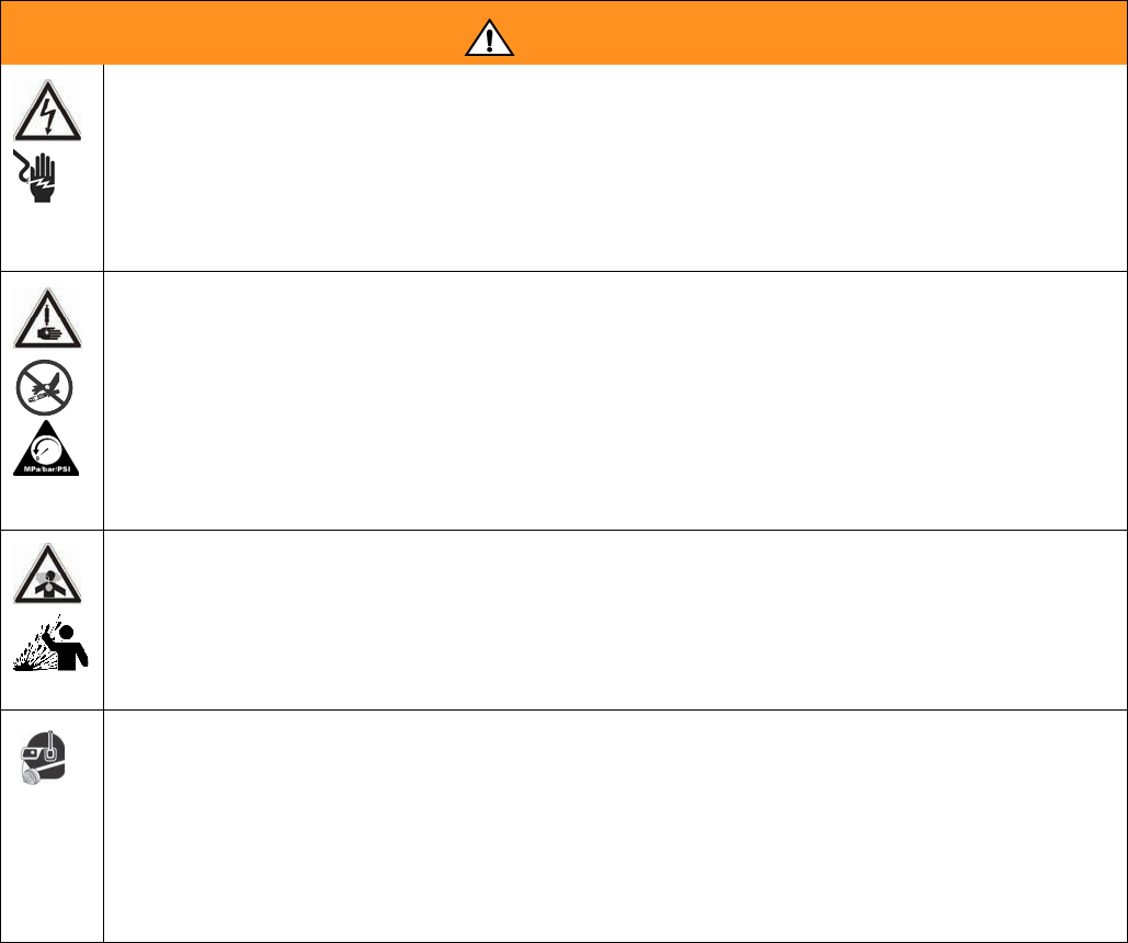
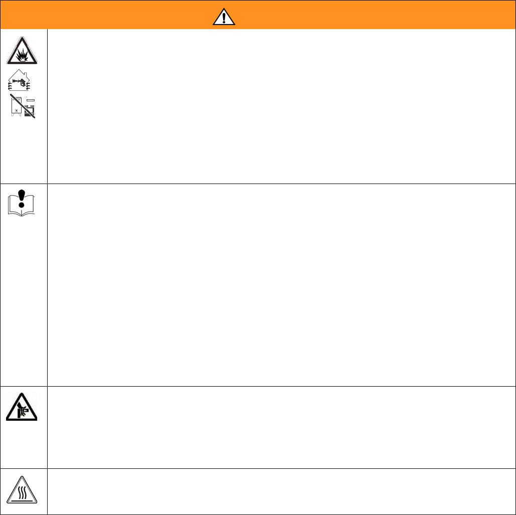
WARNING
ELECTRIC SHOCK HAZARD
Improper grounding, setup, or usage of the system can cause electric shock.
• Turn off and disconnect power cord before servicing equipment.
• Use only grounded electrical outlets.
• Use only 3-wire extension cords.
• Ensure ground prongs are intact on power and extension cords.
• Do not expose to rain. Store indoors.
SKIN INJECTION HAZARD
High-pressure fluid from dispense valve, hose leaks, or ruptured components will pierce skin. This may
look like just a cut, but it is a serious injury that can result in amputation. Get immediate surgical
treatment.
• Do not point dispense valve at anyone or at any part of the body.
• Do not put your hand over the end of the dispense nozzle.
• Do not stop or deflect leaks with your hand, body, glove, or rag.
• Follow Pressure Relief Procedure in this manual, when you stop spraying and before cleaning,
checking, or servicing equipment.
TOXIC FLUID OR FUMES HAZARD
Toxic fluids or fumes can cause serious injury or death if splashed in the eyes or on skin, inhaled, or
swallowed.
• Read MSDS’s to know the specific hazards of the fluids you are using.
• Store hazardous fluid in approved containers, and dispose of it according to applicable guidelines.
• Always wear impervious gloves when spraying or cleaning equipment.
PERSONAL PROTECTIVE EQUIPMENT
You must wear appropriate protective equipment when operating, servicing, or when in the operating
area of the equipment to help protect you from serious injury, including eye injury, inhalation of toxic
fumes, burns, and hearing loss. This equipment includes but is not limited to:
• Protective eyewear
• Clothing and respirator as recommended by the fluid and solvent manufacturer
•Gloves
• Hearing protection
Warnings
12 312759R
FIRE AND EXPLOSION HAZARD
Flammable fumes, such as solvent and paint fumes, in work area can ignite or explode. To help prevent
fire and explosion:
• Use equipment only in well ventilated area.
• Eliminate all ignition sources; such as pilot lights, cigarettes, portable electric lamps, and plastic
drop cloths (potential static arc).
• Keep work area free of debris, including solvent, rags and gasoline.
• Do not plug or unplug power cords or turn lights on or off when flammable fumes are present.
• Ground all equipment in the work area. See Grounding instructions.
• If there is static sparking or you feel a shock, stop operation immediately. Do not use equipment
until you identify and correct the problem.
• Keep a working fire extinguisher in the work area.
EQUIPMENT MISUSE HAZARD
Misuse can cause death or serious injury.
• Do not operate the unit when fatigued or under the influence of drugs or alcohol.
• Do not exceed the maximum working pressure or temperature rating of the lowest rated system
component. See Technical Data in all equipment manuals.
• Use fluids and solvents that are compatible with equipment wetted parts. See Technical Data in all
equipment manuals. Read fluid and solvent manufacturer’s warnings. For complete information
about your material, request MSDS forms from distributor or retailer.
• Check equipment daily. Repair or replace worn or damaged parts immediately with genuine manu-
facturer’s replacement parts only.
• Do not alter or modify equipment.
• Use equipment only for its intended purpose. Call your distributor for information.
• Route hoses and cables away from traffic areas, sharp edges, moving parts, and hot surfaces.
• Do not kink or over bend hoses or use hoses to pull equipment.
• Keep children and animals away from work area.
• Comply with all applicable safety regulations.
MOVING PARTS HAZARD
Moving parts can pinch or amputate fingers and other body parts.
• Keep clear of moving parts.
• Do not operate equipment with protective guards or covers removed.
• Pressurized equipment can start without warning. Before checking, moving, or servicing equipment,
follow the Pressure Relief Procedure in this manual. Disconnect power or air supply.
BURN HAZARD
Equipment surfaces and fluid that’s heated can become very hot during operation. To avoid severe
burns, do not touch hot fluid or equipment. Wait until equipment/fluid has cooled completely.
WARNING
Component Identification
312759R 13
Component Identification
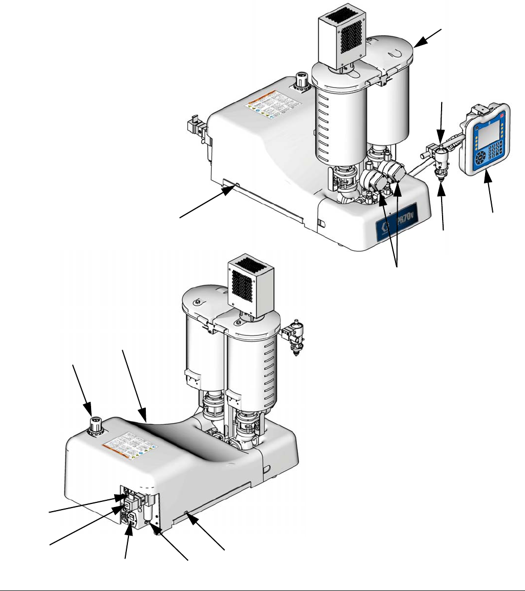
FIG. 1:PR70v with On-Board Tanks and Other Options
101
Key:
101 Tanks
102 Dispense Head
103 Snuff Back Adjustment Knob
104 Advanced Display Module
105 System Air Pressure Regulator
106 System Air Pressure Relief
Switch
107 Power Switch
108 Water Separator
109 Air Inlet
110 Shield Locking Screws
111 Machine Shield
112 Agitator
119 Flow Meters
102
104
105
106
107 108
109
103
ti13389b
ti13388b
110
110
111
119
Component Identification
14 312759R
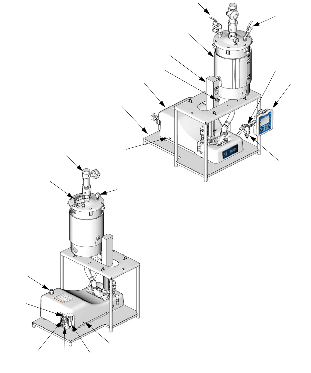
FIG. 2: PR70v with Off-Board Tank, Accumulator, and Other Options
101
Key:
101 Tanks
102 Dispense Head
103 Snuff Back Adjustment Knob
104 Advanced Display Module
105 System Air Pressure Regulator
106 System Air Pressure Relief Switch
107 Power Switch
108 Water Separator
109 Air Inlet
110 Shield Locking Screws
111 Machine Shield
112 Agitator
113 De-gas Valve Tree
114 Tank Air Pressure Gauge
115 Tank Stand
116 Refill Port
117 Accumulator
118 Accumulator Air Pressure Regulator
103
104
117
111
115
112
114
113
105
109 107 108
102
ti12388b
ti12387b
116
113
106
110
110
118
Component Identification
312759R 15
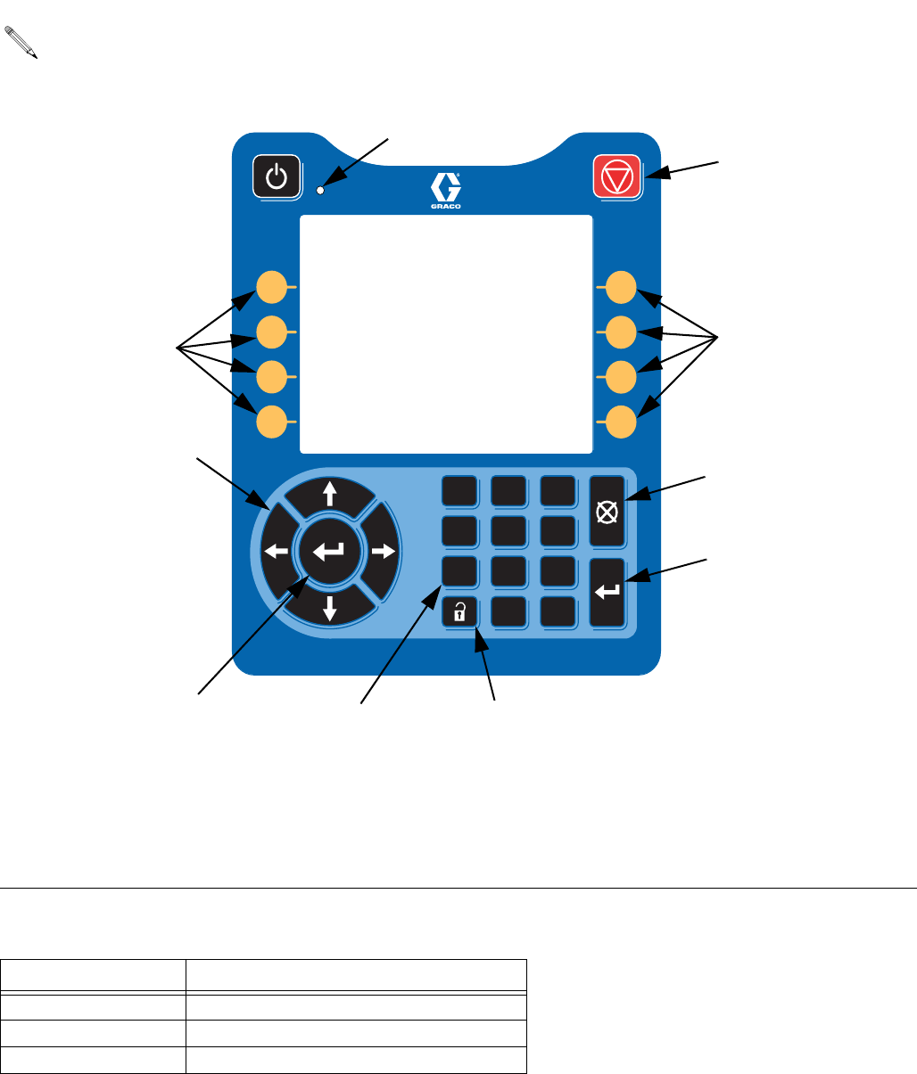
Advanced Display Module (ADM)
Module Status LED Diagnostics
If an invalid key is pressed, the Advanced Display
Module will sound three quick beeps to notify the
user.
FIG. 3
1 2 3
4 5 6
7 8 9
0 .
AB
AC AC
AD
AE
AF
AG
AG AH
Key:
AB Machine Disable Mode Key
AC Soft Keys
AD Directional Keypad
AE Numeric Keypad
AF Abort/Cancel Key
AG Enter Key
AH Alternate Setup/Operation Screens
AJ Module Status LED
AJ
State Description
Solid Green System enabled, valid mode selected
Flashing Yellow System disabled (setup screens)
Solid Yellow System disabled (operation screens)
Screen Navigation Diagram
16 312759R
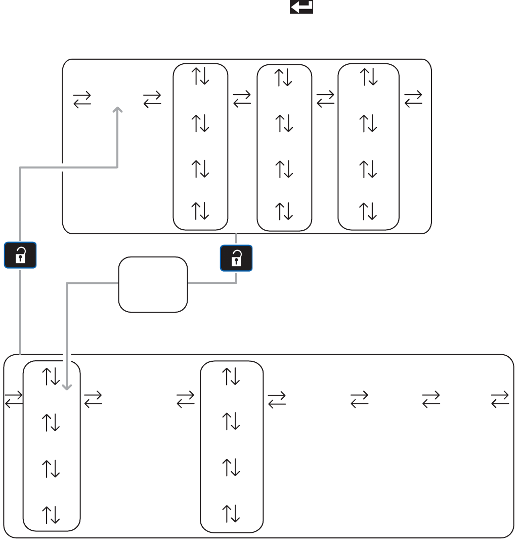
Screen Navigation Diagram
The black arrows in the diagram denote which arrow on
the directional keypad to press to move to the respective
screen.
If the password is enabled, the password will need to be
entered to access the Setup screens. Use the numeric
keypad to enter the password then press the Enter but-
ton ( ).
Home Data #1 Events #1
Data #2
Errors #1
Errors #2 Events #2
Data #... Errors #... Events #...
CalibrationEdit #1 Advanced System
Edit #2
Options #1
Options #2
Edit #... Options #...
Manual
Operation Screens
Setup Screens
Password
Entry
(if enabled)
Grounding
312759R 17
Grounding
This product must be grounded. In the event of an elec-
trical short circuit, grounding reduces the risk of electric
shock by providing an escape wire for the electric cur-
rent. This product is equipped with a cord having a
grounding wire with an appropriate grounding plug. The
plug must be plugged into an outlet that is properly
installed and grounded in accordance with all local
codes and ordinances.
Improper installation of the grounding plug is able to
result in a risk of electric shock. When repair or replace-
ment of the cord or plug is required, do not connect the
grounding wire to either flat blade terminal. The wire
with insulation having an outer surface that is green with
or without yellow stripes is the grounding wire. Do not
modify the plug provided; if it does not fit the outlet, have
the proper outlet installed by a qualified electrician. Only
connect the product to an outlet having the same config-
uration as the plug. Do not use an adapter with this
product.
Installation
Machine Installation
Locate Machine
1. Locate a bench top or open floor area to mechani-
cally mount the machine. Ensure the location has
access to compressed air and AC power and is well
ventilated.
2. Place the machine on the designated location. Allow
the machine to rest on the rubber feet provided.
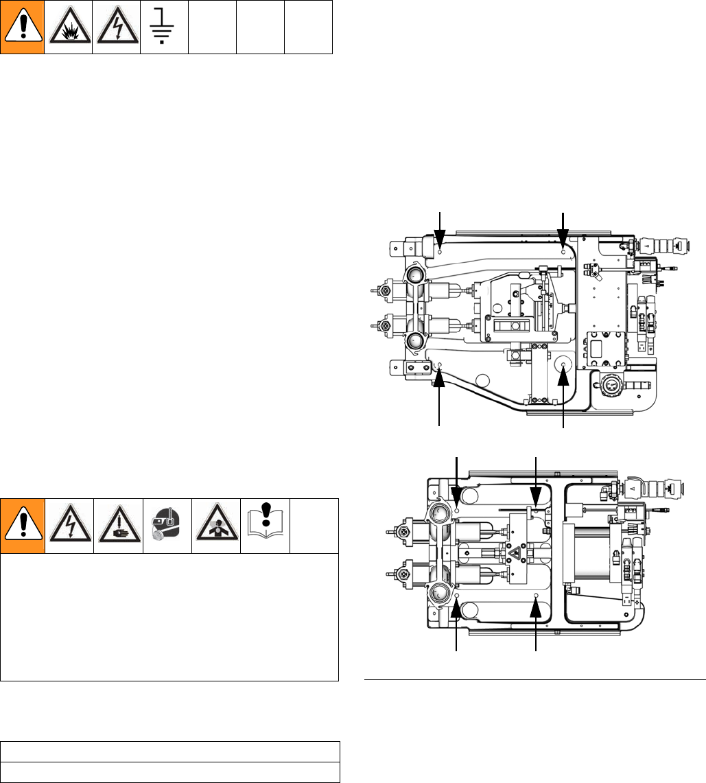
Mount Machine, if Needed
3. Remove the shield locking screws (110) on both
sides then remove the protective shield.
4. Attach the frame to the selected location by install-
ing fasteners (not provided with unit) through the
four mounting holes. See FIG. 4.
Connect Pressurized Air Input
5. Connect a compressed airline to the air inlet (109)
in the back of the machine.
Avoid contact with electrical inter-connects when
connecting electric power to the machine. Avoid con-
tact with Krytox on the pump shaft, PE tank lid, and
PE tank lid gasket. Contact with Krytox causes
flu-like symptoms. Read all manufacturer’s warning
and material MSDS to know the specific hazards of
the material used.
CAUTION
Do not lift the machine by the tanks.
FIG. 4: Mounting Holes
Variable Ratio
Fixed Ratio
ti12713a
ti12712a
Installation
18 312759R
Electrical Requirements
6. Using the power cord provided, connect AC power
(100-240V, 50/60 Hz, single-phase) to the machine.
Ground System
The equipment must be grounded. Grounding reduces
the risk of static and electric shock by providing an
escape wire for the electrical current due to static build
up or in the event of a short circuit.
7. The machine is grounded through the power cord.
• Be sure that the plug is plugged into an outlet that is
properly installed and grounded in accordance with
all local codes and ordinances.
• Only connect the product to an outlet having the
same configuration as the plug.
Flush the System
8. The machine is tested at the factory with mineral oil.
Flush the machine before first use.
Improper wiring may cause electric shock or other
serious injury if work is not performed properly. Have
a qualified electrician perform any electrical work. Be
sure your installation complies with all National, State
and Local safety and fire codes.
Installation
312759R 19
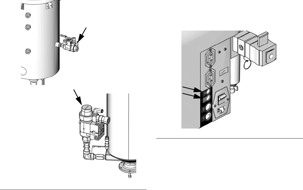
Tank Refill Kit 256577
Installation
The tank refill kit is shipped uninstalled. The tank refill kit
can be installed on the lid of the tank or on the side of
the tank. See FIG. 5 and FIG. 7.
Install the tank refill kit in the tank lid if using heat or agi-
tation or if a slinger blade is installed in the tank. Install
the tank refill kit in the side of the tank if using thicker
materials. Pouring thick materials into the tank from the
lid can result in air added to the material. For all other
applications, install the tank refill kit in either location.
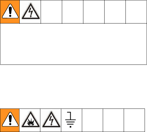
Tank Refill Kit Lid Installation
1. Use PTFE tape and the fittings supplied to install
the refill kit. See FIG. 5.
2. For tank refill kits installed on the A side tank,
plug the tank refill kit power cord into the “A” con-
nector located at the back of the machine. See FIG.
6.
For tank refill kits installed on the B side tank,
plug the tank refill kit power cord into the “B” con-
nector located at the back of the machine. See FIG.
6.
FIG. 5: Tank Lid Installation
ti13386a
ti13387a
30 L or 60 L Tanks
7.5 L Tanks
FIG. 6: Tank Refill Kit Power Source
ti12583a
Installation
20 312759R
Tank Refill Kit Side Installation
1. Use PTFE tape and the fittings supplied to install
the refill kit as shown in FIG. 7.
2. For tank refill kits installed on the A side tank,
plug the tank refill kit power cord into the “A” con-
nector located at the back of the machine. See FIG.
8.
For tank refill kits installed on the B side tank,
plug the tank refill kit power cord into the “B” con-
nector located at the back of the machine. See FIG.
8.
FIG. 7: Side Installation
ti13385a
ti12591b
7.5 L Tanks
30 L or 60 L Tanks
FIG. 8: Tank Refill Kit Power Source
ti12583a
Startup
312759R 21
Startup
1. Locate power switch (107) at rear of machine and
turn power on. The display module will automatically
turn on and begin to load.
2. Slide the system air pressure relief switch (106) up.
It is the yellow tab at the left, rear of the machine.
The hole in the tab should not be showing.
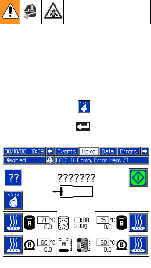
3. If the machine is in Disabled Mode, press the Select
Operating Mode button ( ) repeatedly to exit
Disabled mode and to select a new operating mode.
Press the Enter button ( ) to accept the new
operating mode.
FIG. 9: Disabled Mode
Setup
22 312759R
Setup
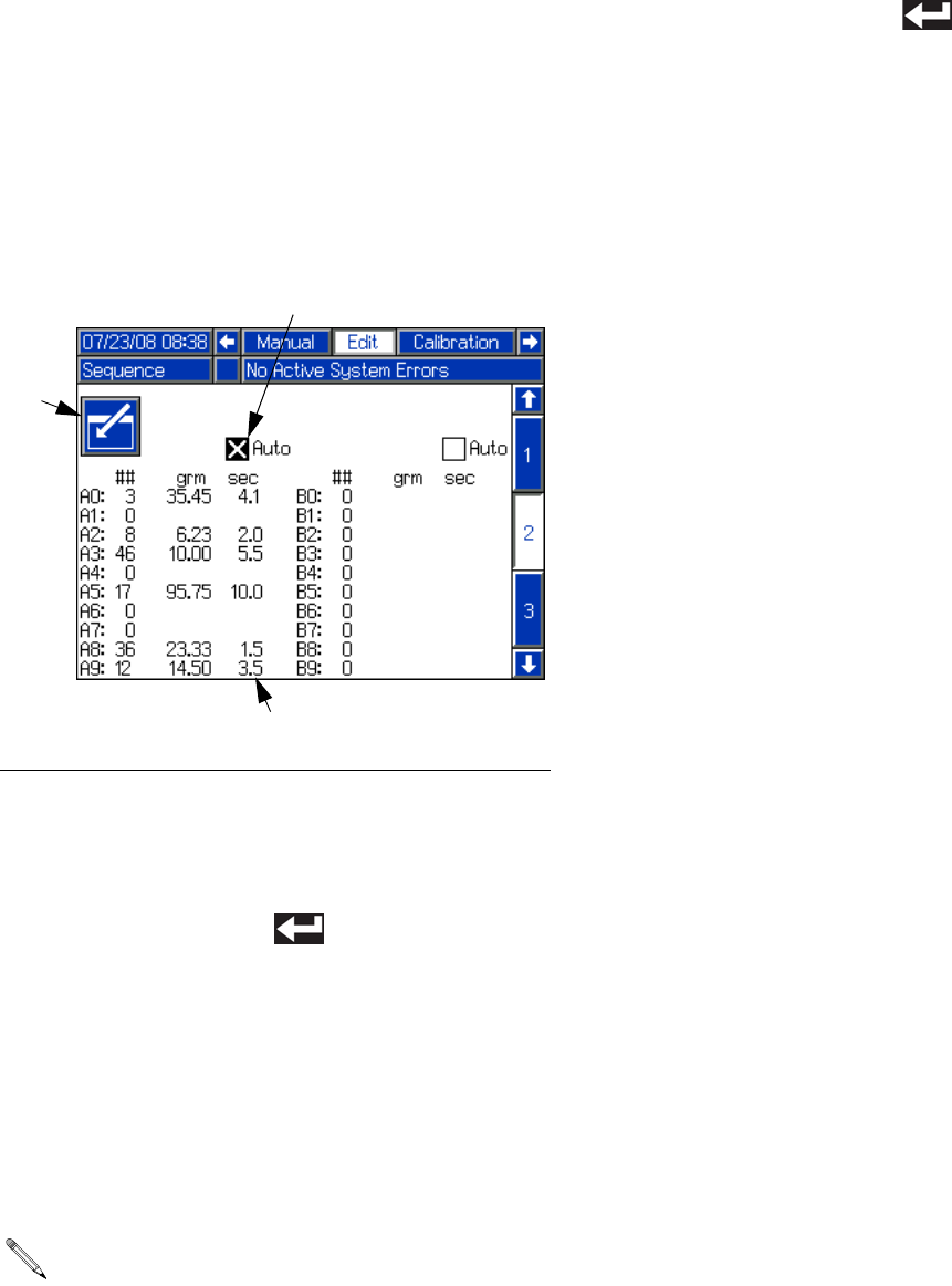
Setup Screens
Edit Screens
Enter/Exit Screen Button
Many screens use the Enter/Exit Screen button (GA).
When scrolling through screens using the arrow keys,
the information in each screen can be seen but not
changed. To change the information in a screen that has
the Enter/Exit Screen button (GA), first press the
Enter/Exit Screen button to enter the screen. Once in
the screen, use the arrow keys to navigate and use the
arrow keys, number keys, and enter key as applicable to
change the values.
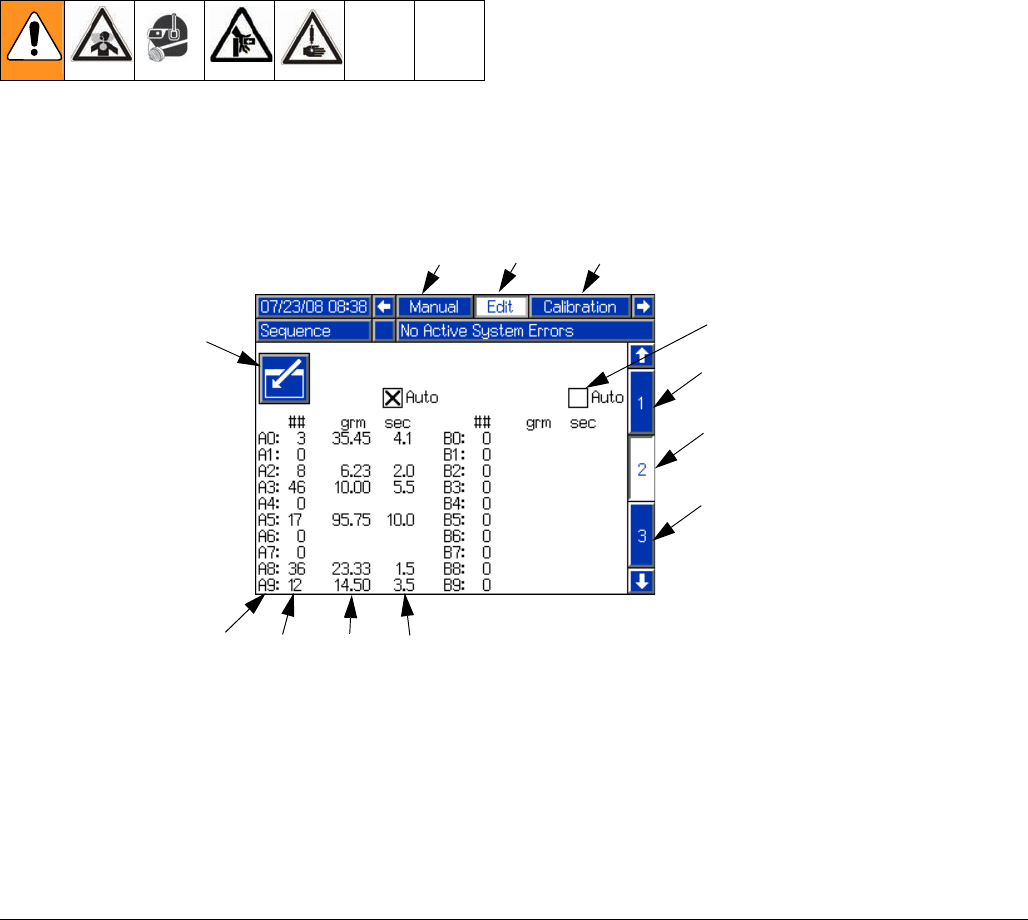
FIG. 10
GA
Key:
GA Enter/Exit Screen button
GB Active Screen Name
GC Shot Number (Edit Screen #1) or
Sequence Position (Edit Screens
#2-#5)
GD Shot Number (Edit Screens #2-#5
only)
GE Shot Size
GF Delay Between Shots (Edit Screens
#2-#5 only)
GG Enable/Disable Auto Sequencing
Mode (Edit Screens #2-#5 only)
GH Adjacent Screen Names
GJ Active Screen Number
GK Adjacent Screen Numbers
GJ
GC GEGD GF
GG
Edit Screen #2 Shown
GK
GK
GB GH
GH
Setup
312759R 23
Overview
There are five Edit screens. Edit Screen #1 is the Shot
Editing screen and Edit Screens #2-#5 are Sequence
Editing screens. Edit Screen #1 shows Shot #1 through
Shot #50. Each shot has a defined shot size that is mea-
sured in grams.
Edit Screens #2-#5 show Sequence A through
Sequence G. Each sequence has ten positions; shown
as A0 to A9 in FIG. 10. Each of the ten positions in the
sequence uses one of the Shot Numbers (GD) defined
in Edit Screen #1. The third column in FIG. 10 shows the
shot sizes (GE) for the selected Shot Numbers.
When operating in Sequence mode and a shot in the
sequence is finished, the machine will automatically
select the next position in the sequence that uses a Shot
Number with a non-zero shot size.
When operating in Sequence mode, there is an option to
allow the machine to automatically perform all of the
shots in the sequence with a preset delay between
shots. The delay between Shots (GF) is shown in the
fourth column. This process is called Auto-Sequencing.
Edit Shot Size
To edit the defined shot size (GE) for a certain shot
number using Edit Screen #1, use the following proce-
dure.
1. Navigate to the Edit Screen #1. See Screen Navi-
gation Diagram, page 16.
2. Press the Enter/Exit Screen button (GA) to enter the
screen.
3. Use the arrow keys to navigate to the shot size for
the Shot Number to be changed.
4. Use the numeric keypad to enter the desired shot
size in grams.
5. Press the Enter button ( ) to accept the shot
size and exit editing mode.
6. Press the Enter/Exit Screen button (GA) to exit the
screen.
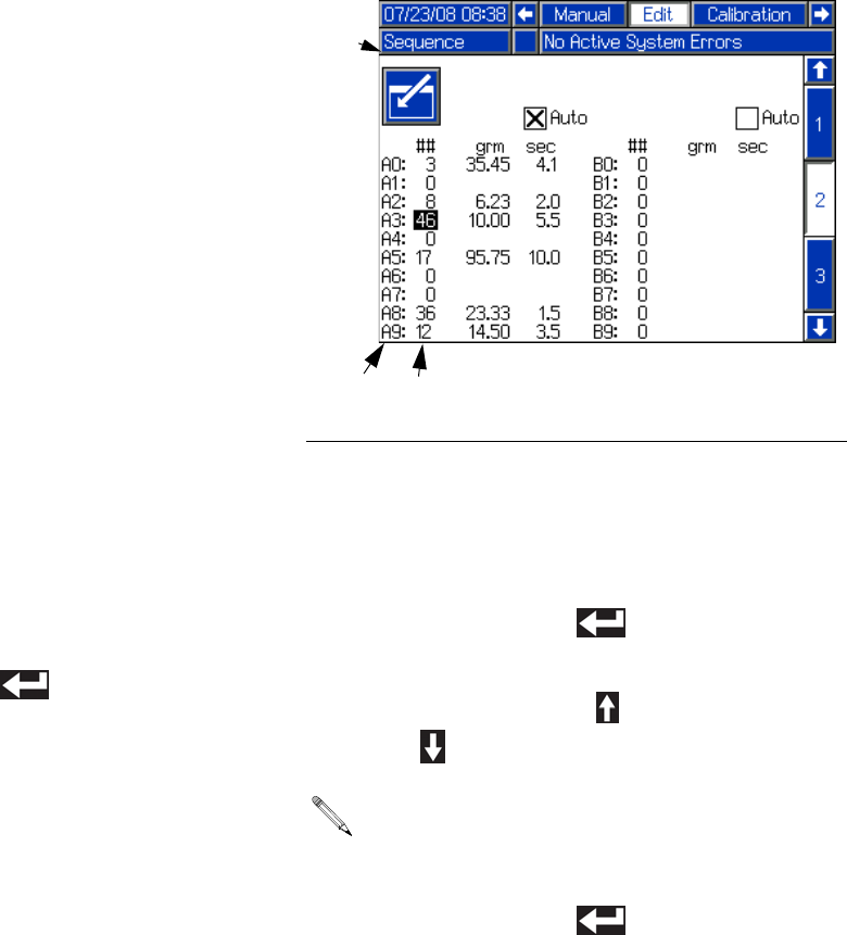
Edit Shot Sequence
To change which Shot Numbers (GD) from Edit Screen
#1 are used in a sequence, use the following procedure.
1. Navigate to the Edit Screen that contains the
Sequence to be changed. See the list below, then
see Screen Navigation Diagram, page 16.
• Sequences A and B are on Edit Screen #2
• Sequences C and D are on Edit Screen #3
• Sequences E and F are on Edit Screen #4
• Sequence G is on Edit Screen #5
2. Press the Enter/Exit Screen button (GA) to enter the
screen.
3. Each Sequence Position (GC) uses a Shot
Number (GD). Use the arrow keys to navigate to the
Shot Number for the sequence position to be
changed.
4. Press the Enter button ( ) to enter editing
mode.
5. Use the Up Arrow button ( ) or the Down Arrow
button ( ) to change the Shot Number.
6. Press the Enter button ( ) to accept the Shot
Number and exit editing mode.
FIG. 11: Edit Shot Number in Sequence
Only Shot Numbers with non-zero shot sizes will be
available for selection.
GA
GC GD
Setup
24 312759R
7. Press the Enter/Exit Screen button (GA) to exit the
screen.
Edit Auto-Sequencing
To edit whether the machine automatically performs all
shots in a sequence, use the following procedure.
1. Navigate to the Edit Screen that contains the
Sequence to be changed. See Screen Navigation
Diagram, page 16.
2. Press the Enter/Exit Screen button (GA) to enter the
screen.
3. Use the arrow keys to navigate to the Enable/Dis-
able Auto Sequencing Mode (GG) box for the
sequence position to be changed.
4. Press the Enter button ( ) to add or remove the
“X” from the box.
5. Navigate away from the Enable/Disable Auto
Sequencing Mode (GG) box to accept the change.
6. If Auto-Sequencing is enabled, the delay between
shots can be changed.
a. Navigate to the delay between shots (GF) for
the Sequence Position to be changed.
b. Use the numeric keypad to enter the desired
delay time in seconds.
c. Press the Enter button ( ) to accept the
delay and exit editing mode.
7. Press the Enter/Exit Screen button (GA) to exit the
screen.
FIG. 12: Turn Auto-Sequencing On/Off
The delay shown in a given Sequence Position row
is the delay prior to beginning the next shot in the
sequence.
GA
GG
GF
Setup
312759R 25
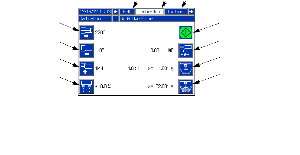
Calibration Screen
See Piston Position Calibration on page 37, Phasing
Adjustment on page 40, Adjust Open Dispense
Valve (ODV) Timing on page 43, and Shot Calibration
on page 47 for Calibration Screen use.
FIG. 13
FA
Key:
FA Start/Stop Shot
FB Update Piston Extended Position
FC Update Piston Retracted Position
FD Update Piston Engaged Position
FE Piston Phasing
FF Adjust Open Dispense Valve Timing
FG Initiate Small Calibration Shot
FH Initiate Large Calibration Shot
FJ Active Screen Name
FK Adjacent Screen Names
FB
FC
FD
FE
FF
FG
FH
FJ FK
FK
Setup
26 312759R
Options Screens
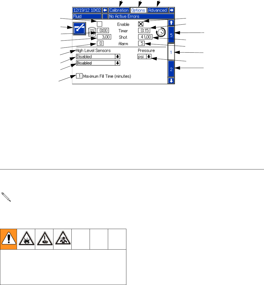
Fluid Options, Screen #1
Recirculation and Purge Timers The Purge Timer and Recirculation Timer behave in a
similar way, with a certain shot size (HD, HH) being exe-
cuted after the timer delay (HC, HG) has elapsed. The
difference is that the purge timer operates with the dis-
pense valve open so a purge shot is executed. The
recirculation timer operates with the dispense valve
closed so when the shot is executed no material is dis-
pensed.
Both timers feature an adjustable alarm to warn the user
that the piston drive block is to begin moving. The alarm
setting is the number of seconds before the shot is to be
executed.
FIG. 14
Key:
HA Enter/Exit Screen
HB Purge Timer Enable/Disable
HC Purge Timer Delay
HD Purge Timer Shot Size
HE Purge Timer Alarm (seconds)
HF Recirculation Timer Enable/Disable
HG Recirculation Timer Delay
HH Recirculation Timer Shot Size
HJ Recirculation Timer Alarm (seconds)
HK Low Level Sensors Enable/Disable
(For FCMB Systems)
HL Tank A High Level Sensor Options
HM Tank B High Level Sensor Options
HN Maximum Fill Time
HR Active Screen Name
HS Adjacent Screen Names
HT Active Screen Number
HU Adjacent Screen Numbers
HV Pressure Units of Measure Selection
HA
HB
HD
HE
HL
HM
HN
HK
HC
HF
HG
HH
HJ
HU
HT
HU
HR HS
HS
HV
To use Recirculation mode, 3-way ball valves must
be installed at the dispense head. Fluid lines must
be installed going from the ball valves back to the
tank.
When Recirculation mode is enabled, both recircula-
tion ball valves must be turned to return material
back to the tank. Only turning one valve may result in
a pressure imbalance exceeding the machine’s maxi-
mum working pressure.

Setup
312759R 27
Level Sensors
The Low Level Sensors can be enabled or disabled. Dis-
abling the low level sensors disables low level alarms. If
the Low Level Sensors are disabled, the tank icons on
the Home screen will be grayed out.
With High Level Sensors installed, auto-Refill can be
used. The High Level Sensors have multiple Auto-Refill
modes ranging in function.
• High Level Auto-Refill refills the tank when mate-
rial is below the high level sensor. This mode is rec-
ommended for applications with temperature
control.
• Empty Auto-Refill refills the tank when a low level
condition is seen.
• Manual Auto-Refill requires the user to initiate tank
refill.
• Monitor High Level mode simply displays the cur-
rent fluid level on the Home screen. This selection
should be chosen only if low level sensors are
installed for the respective tank.
•Accumulator mode refills the accumulators auto-
matically when a low level condition is seen.
Maximum Fill Time
The Maximum Fill Time (HN) function allows the user to
specify a maximum amount of time for refilling the tank.
If after the input amount of time the tanks are not full, an
alarm will be displayed.
Enable/Disable Timers and Low Level Sensors
1. Press the Enter/Exit Screen button (HA).
2. Use the arrow keys to navigate to the item to be
changed.
3. Press the Enter button ( ) to enable or disable
the selected item.
Edit Numeric Values
1. Press the Enter/Exit Screen button (GA) to enter the
screen.
2. Use the arrow keys to navigate to the item to be
changed.
3. Use the numeric keypad to enter the new value.
4. Press the Enter button ( ) to accept the new
value.
5. Press the Enter/Exit Screen button (GA) to enter the
screen.
Edit High Level Sensor Drop-Down Boxes
1. Press the Enter/Exit Screen button (GA) to enter the
screen.
2. Use the arrow keys to navigate to the item to be
changed.
3. Press the Enter button ( ) to open the
drop-down menu.
4. Use the up and down arrow keys to select the new
value.
5. Press the Enter button ( ) to accept the new
value.
6. Press the Enter/Exit Screen button (GA) to enter the
screen.
See the Feed Systems manual referenced at the
beginning of this manual for Vacuum Auto-Fill pro-
cedure.
Setup
28 312759R
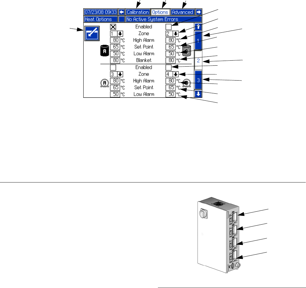
Heat Options, Screen #2
The Heat Options Setup Screen includes options for the
tank and hose heaters. Each tank and hose heater can
be enabled and disabled and each have their own set-
tings.
Zone Numbers
Each tank and hose heater is assigned to a specific
“zone” number. The zone number refers to the zone
number on the Integrated Heat Assembly. Each zone
number has a label above it. See FIG. 16.
The zone number specified for each option on the Heat
Options Setup Screen needs to match how the system
is connected. For instance, if tank A is connected to
zone #1, then zone #1 needs to be selected for tank A
heat.
Temperature Settings
Each tank and hose heater has a high and low tempera-
ture alarm and a temperature setpoint. The tanks also
have a blanket heater temperature setpoint.
An alarm will sound when the material temperature is
outside of the range given by the high and low tempera-
ture setpoints. also, dispensing may be disabled
depending on the selections made in the System
Options Setup Screen, see page 30.
FIG. 15
JA
Key:
JA Enter/Exit Screen
JB Enable/Disable Tank Heater Zone
JC Zone Number Used for Tank Heat Control
JD Tank Heat High Temperature Alarm
JE Tank Heat Temperature Setpoint
JF Tank Heat Low Temperature Alarm
JG Tank Heat Blanket Temperature Setpoint
JH Enable/Disable Hose Heater Zone
JJ Zone Number Used for Hose Heater Control
JK Hose Heater High Temperature Alarm
JL Hose Heater Temperature Setpoint
JM Hose Heater Low Temperature Alarm
JN Active Screen Name
JP Adjacent Screen Names
JR Active Screen Number
JS Adjacent Screen Numbers
JB
JC
JD
JE
JF
JH
JJ
JK
JL
JM
JG
JN JP
JP
JS
JR
JS
FIG. 16: Integrated Heat Assembly, Zone Numbers
Zone #3
Zone #2
Zone #1
ti12593a
Zone #4
Assembly
LC0253 Shown

Setup
312759R 29
Enable/Disable Heat Options
All heat options can be enabled or disabled. All options
that are installed should be enabled and all that are not
installed should be disabled. All enabled heat options
can be turned on and off from the Home Screen, see
page 53. To enable or disable heat options, perform the
following procedure.
1. Press the Enter/Exit Screen button (JA).
2. Use the arrow keys to navigate to the item to be
changed.
3. Press the Enter button ( ) to enable or disable
the selected item.
4. Navigate away from the Enable/Disable field to
accept the change.
Change Zone Number
To change a zone number, the applicable tank or hose
heater must be disabled.
1. Press the Enter/Exit Screen button (JA).
2. Disable all heat options that will have their zone
number changed.
3. Change zone number for all heat options just dis-
abled.
a. Use the arrow keys to navigate to the Heat
Option Zone field (JC, JJ).
b. Press the Enter button ( ) to enter editing
mode.
c. Use the Up Arrow button ( ) or the Down
Arrow button ( ) to change the item value.
d. Press the Enter button ( ) to exit editing
mode.
Edit Temperature Settings
1. Press the Enter/Exit Screen button (JA) to enter the
screen.
2. Use the arrow keys to navigate to the item to be
changed.
3. Use the numeric keypad to enter the desired tem-
perature in the displayed units (Celsius or Fahren-
heit).
4. Press the Enter button ( ) to accept the new
value and exit editing mode.
5. Press the Enter/Exit Screen button (JA) to exit the
screen.
No two zones may have the same zone number
assigned at any point. To change a heat option
zone number to a zone number already assigned to
another heat option, the existing assignment must
first be changed to either another zone number
or “--”.
Setup
30 312759R
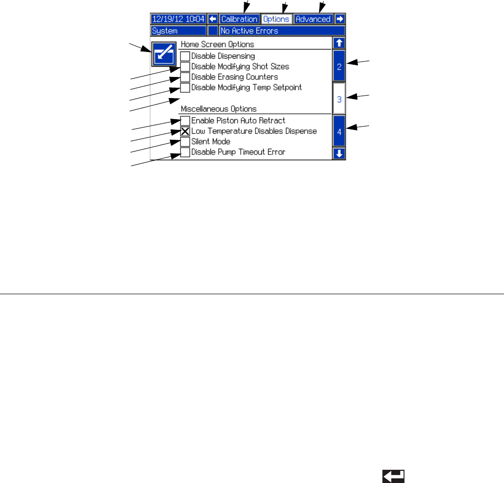
System Options, Screen #3
Primary Run Screen Options
These options disable certain functions on the Home
Screen. Some of the functions can be performed using
the setup screens. When using these options, it is rec-
ommended that the Setup screens are protected by a
password; see Advanced Setup Screen, page 34.
• Disable Dispensing disables dispensing from the
Home screen.
• Disable Modifying Shot Sizes disables editing
shot size definitions from the Home screen.
• Disable Erasing Counters disables erasing shot
counters on the Data screen.
• Disable Changing Temperature Setpoint disables
changing the temperature setpoint from the Home
screen.
Miscellaneous Options
• Enable Piston Auto Retract enables the piston to
automatically retract after every shot when in Oper-
ator (Manual) mode. Normally the piston only
retracts after it completes the entire stroke.
• Low Temperature Disables Dispense disables
dispensing if the material temperature is below the
low temperature setpoint.
• Silent Mode disables all audible alerts.
Enable/Disable Options
1. Press the Enter/Exit Screen button (LA) to enter the
screen.
2. Use the arrow keys to navigate to the item to be
changed.
3. Press the Enter button ( ) to enable or disable
the selected item.
4. Navigate away from the Enable/Disable field to
accept the change.
5. Press the Enter/Exit Screen button (LA) to exit the
screen.
FIG. 17
LA
Key:
LA Enter/Exit Screen
LB Disable Dispensing Option
LC Disable Modifying Shot Sizes Option
LD Disable Erasing Counters Option
LE Disable Changing Temperature Setpoint
Option
LF Enable Piston Auto-Retract Option
LG Low Temperature Disables Dispense
Option
LH Silent Mode Option
LJ Active Screen Name
LK Adjacent Screen Names
LL Active Screen Number
LM Adjacent Screen Numbers
LN Disables Pump Stationary During
Dispense Timeout Error
LB
LC
LD
LE
LF
LG
LH
LJ
LK LK
LM
LL
LM
LN
Setup
312759R 31
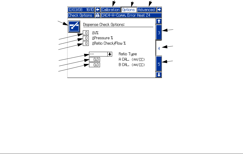
Dispense Check Options, Screen #4
Change in Velocity, Change in Pressure, Change in
Ratio or Volume
NOTE: The machine must have pressure transducers
installed for Change in Pressure to be available. The
machine must have flow meters installed for Change in
Ratio or Volume to be available. The Change in Velocity
function is available on all machines. If a non-zero value
is entered for an unavailable function, an error will be
displayed.
During machine calibration the machine measures and
obtains base values for piston speed, fluid pressure, and
fluid ratio or volume. The machine also records when
the pressure rises for each side, to get a base value for
phasing.
NOTE: The pressure transducers are designed to work
with the hoses available in the PR70 configurator. If they
are used with other hoses, unexpected alarms may
occur.
When any of these three dispense check features are
enabled by entering a value other than zero, the
machine will compare the value seen during each dis-
pense to the values measured during calibration. If the
values are farther than the input percentage from the
calibration values, an error is shown after the dispense.
See Error Codes on page 71. This warning signals the
user of a less than optimal dispense or possible
machine malfunction.
The available input values for Change in Velocity and
Change in Pressure are 0 (off), 20, 40, or 60 percent.
The acceptable input value for Change in Ratio or Vol-
ume are 0 (off), or 1 through 10 percent. If an invalid
number is entered, it will automatically be rounded to the
nearest valid entry.
FIG. 18
Key:
PA Enter/Exit Screen
PB Change in Velocity
PC Change in Pressure
PD Change in Ratio or Volume
PE Ratio Type (Volume or Weight)
PF A Side Flow Meter Calibration Factor
PG B Side Flow Meter Calibration Factor
PH Active Screen Name
PJ Adjacent Screen Names
PK Active Screen Number
PL Adjacent Screen Numbers
PJ PJ
PH
PA
PB
PC
PD
PE
PF
PG
PL
PK
PL
Setup
32 312759R
Ratio Type
Fluid ratio can be monitored as either weight-ratio or vol-
ume-ratio. If the ratio type selected is “Volume”, the cali-
bration factor for each installed flow meter must be
entered in the calibration factor fields (PF, PG). The cal-
ibration factor is found on the flow meter data sheet
shipped with the machine.
After each shot, the ratio for that shot will be shown on
the Home screen. If weight-ratio is selected, the ratio will
be shown to the left of the piston position graphic. If vol-
ume-ratio is selected, the ratio will be shown to right of
the piston position graphic.
Setup
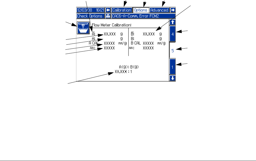
312759R 33
Flow Meter Calibration, Screen #5
Proper calibration of the flow meters ensures that ratio
and weight monitoring perform optimally. Flow meter
calibration is only necessary if the ratio type selected on
Options Screen #4 is “Volume”. After the flow meter cali-
bration factors are entered in Options Screen #4, the
machine will accurately measure volume and the mate-
rial weight dispensed counters will start tracking dis-
penses.
See Flow Meter Calibration on page 48.
FIG. 19
Key:
RA Enter/Exit Screen
RB Average Calibration Weight
RC Material Weight Entry
RD Cycles per Gram
RE Total Cycles
RF A Side Information
RG B Side Information
RH A to B Weight Ratio
RJ Active Screen Name
RK Adjacent Screen Names
RL Active Screen Number
RM Adjacent Screen Numbers
RK RK
RARA
RB
RC
RD
RE
RF
RG
RM
RM
RH
RJ
RL
Setup
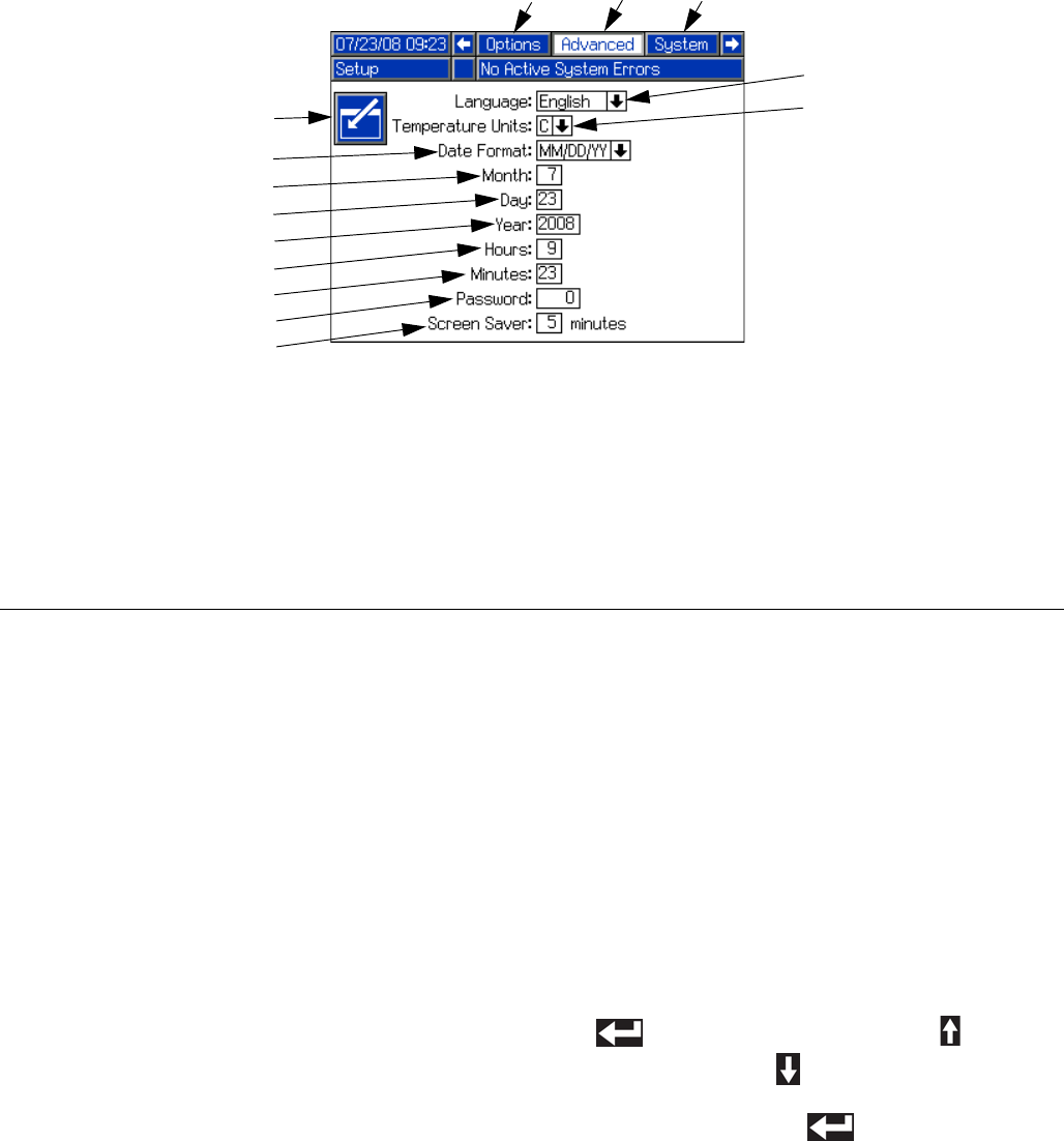
34 312759R
Advanced Setup Screen
Password
If a password other than “0” is entered, the password is
automatically enabled. The password protects entry into
the setup screens. With the password enabled, the
restricted user may still be able to change shot sizes,
erase counters, or modify temperatures depending on
the options enabled on the System Options Setup
Screen. To prohibit the restricted user from changing
these settings, enable the appropriate options; see Sys-
tem Options, Screen #3 on page 30.
Screen Saver
The screen saver turns off the screen backlighting after
the given number of minutes. To disable the screen
saver, press any button.
Languages
The language selection feature will change the lan-
guage of all text on the display module. Available lan-
guages are English, Spanish, French, German,
Chinese, Japanese, Korean, Russian, and Italian.
Date Formats
There are three available formats: MM/DD/YY,
DD/MM/YY, and YY/MM/DD.
Edit Settings
1. Press the Enter/Exit Screen button (KL) to enter the
screen.
2. Use the arrow keys to navigate to the item to be
changed.
3. For numeric entries, use the numeric keypad to
enter the new value.
For non-numeric settings, press the Enter button
( ) then use the Up Arrow button ( ) and the
Down Arrow button ( ) to change the selection.
4. Press the Enter button ( ) to accept the new
value or selection and exit editing mode.
FIG. 20
Key:
KA Language Selection
KB Temperature Units Selection
KC Date Format
KD Month
KE Day
KF Four Digit Year
KG Hours (24 Hour Clock)
KH Minutes
KJ Numeric Password
(four digits allowed)
KK Screen Saver
KL Enter/Exit Screen
KM Active Screen Name
KN Adjacent Screen Names
KA
KB
KC
KD
KE
KF
KG
KH
KJ
KL
KK
KM KN
KN
Setup
312759R 35
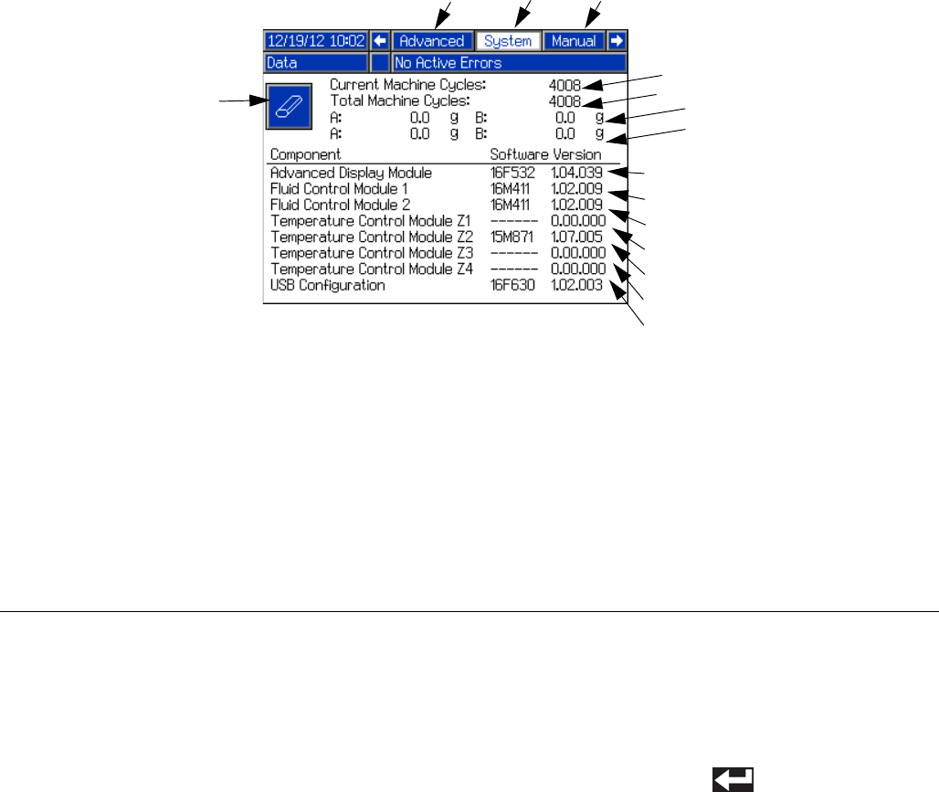
System Data Screen
Software Version
Software version will read “0.00.000” if component can-
not be seen by the ADM. This is the result of the compo-
nent not being installed or a communication error.
Machine Cycles
A machine cycle is one full extension and retraction of
the machine piston. The Current Machine Cycles Coun-
ter is resettable and the Total Machine Cycles Counter is
the number of cycles since the ADM was installed.
Reprogramming the ADM will not reset the Total
Machine Cycles counter.
Reset Current Machine Cycles Counter
1. Press the Enter/Exit Screen button (MA) to enter the
screen. The Current Machine Cycles count will be
highlighted.
2. Press the Enter button ( ) to reset the Current
Machine Cycles counter.
3. Press the Enter/Exit Screen button (MA) to exit the
screen.
FIG. 21
Key:
MA Enter/Exit Screen
MB Current Machine Cycles Counter
MC Total Machine Cycles Counter
MD Advanced Display Module Software
Version
ME Fluid Control Module #1 Software
Version
MF Fluid Control Module #2 Software
Version
MG Temperature Control Module -
Zone #1 Software Version
MH Temperature Control Module -
Zone #2 Software Version
MJ Temperature Control Module -
Zone #3 Software Version
MK Temperature Control Module -
Zone #4 Software Version
ML Active Screen Name
MM Adjacent Screen Names
MN Resettable material weight counter
MP Non-resettable material weight
counter
MA
MB
MC
MD
ME
MF
MG
MH
MJ
MK
ML MM
MM
MN
MP
Setup
36 312759R
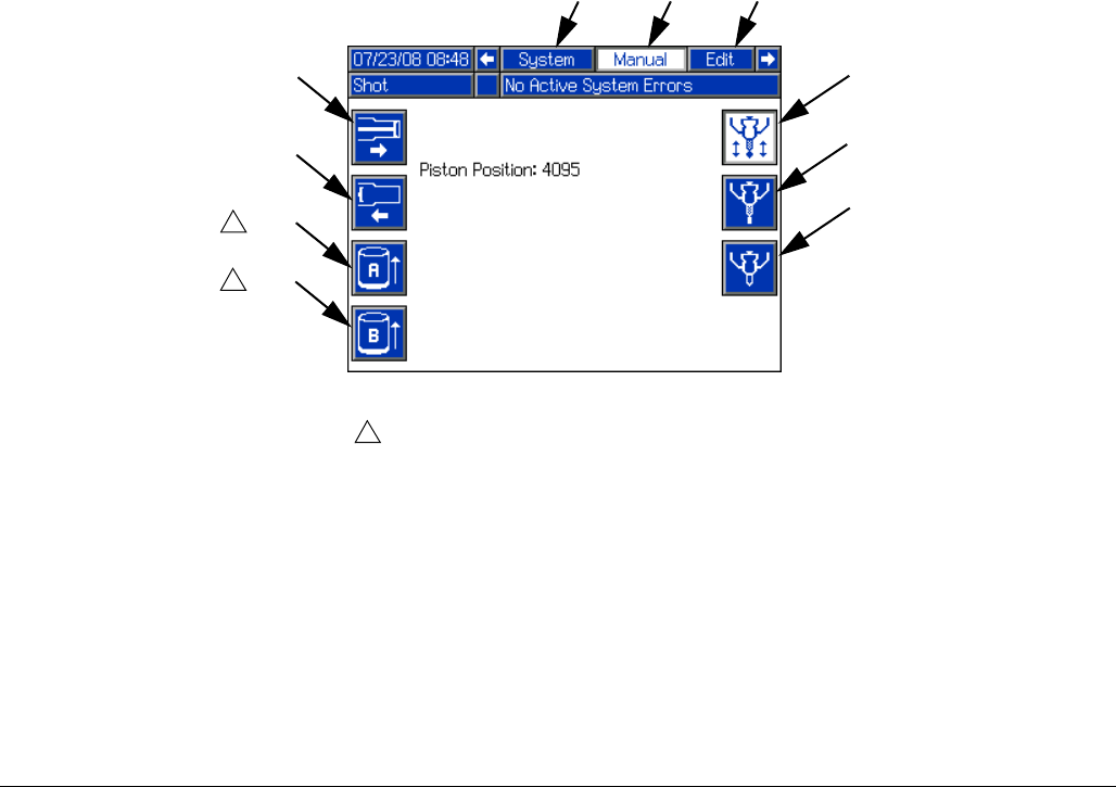
Manual Screen
The Manual screen overrides control of some machine
actions. This can be useful in troubleshooting. To per-
form any of the available machine actions shown on the
Manual screen, press the appropriate button.
FIG. 22
EG
Key:
EA Extend Piston Command
EB Retract Piston Command
EC Tank A Refill Valve Command Open
ED Tank B Refill Valve Command Open
EE Dispense Valve Command Close
EF Dispense Valve Command Open
EG Revert to Automatic Dispense Valve Operation
EH Active Screen Name
EJ Adjacent Screen Names
EA
EB
EC
ED
EF
EE
1
Valve will open for approximately two seconds.
1
1
EHEJ EJ
Setup
312759R 37
Edit Settings
• Edit Display Settings:
See Advanced Setup Screen, page 34.
• Edit Shots and Sequences:
See Edit Screens, page 22.
• Edit Recirculation and Purge Timers:
See Fluid Options, Screen #1, page 26.
• Edit Level Sensor Settings:
See Fluid Options, Screen #1, page 26.
• Edit Temperature Control Settings:
See Heat Options, Screen #2, page 28.
• Edit System Options:
See System Options, Screen #3, page 30.
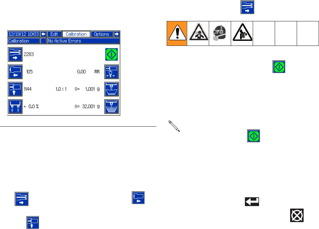
Piston Position Calibration
The position sensor assigns a numeric value to the loca-
tion of the piston. Higher numbers indicate the piston is
extended and lower numbers indicate the piston is
retracted.
The Piston Position Calibration procedure teaches the
machine the location of the most extended piston posi-
tion ( ), the most retracted piston position ( ),
and the position where the piston engages the pump
cylinder ( ).
Perform the Piston Position Calibration procedure when
first setting up the machine. Also perform this procedure
if the linear position sensor, piston, or any electronic
component has been replaced.
Prepare Machine for Calibration
1. Ensure that both piston shafts are screwed all the
way into the drive block.
2. Ensure there is a sufficient amount of material in the
tanks.
3. Navigate to the Calibration screen. See Screen
Navigation Diagram, page 16.
4. Place a waste container under the dispense valve to
capture any dispensed material.
5. Ensure system air pressure relief switch (106) is in
the up position and the system air pressure
regulator (105) shows air pressure in the system.
Extended Piston Position
6. With air pressure applied to the machine, press the
Extend Piston button ( ).
7. Press the Start/Stop Shot button ( ). The piston
will fully extend and a number 3600-3900 should be
displayed. If a number significantly different from
3600-3900 is displayed, ensure the air cylinder air
line connections are not switched and that the linear
position sensor is installed correctly.
8. Press the Enter button ( ) to accept the new
value or press the Abort/Cancel button ( ) to
keep the previous value.
FIG. 23: Calibration Screen If the piston does not extend after pressing the
Start/Stop Shot button ( ) the air pressure may
need to be increased. Use system air pressure
regulator (105) to increase the air pressure in incre-
ments of 10 psi until the piston activates. Material
will be dispensed when adequate pressure is
achieved.
Setup
38 312759R
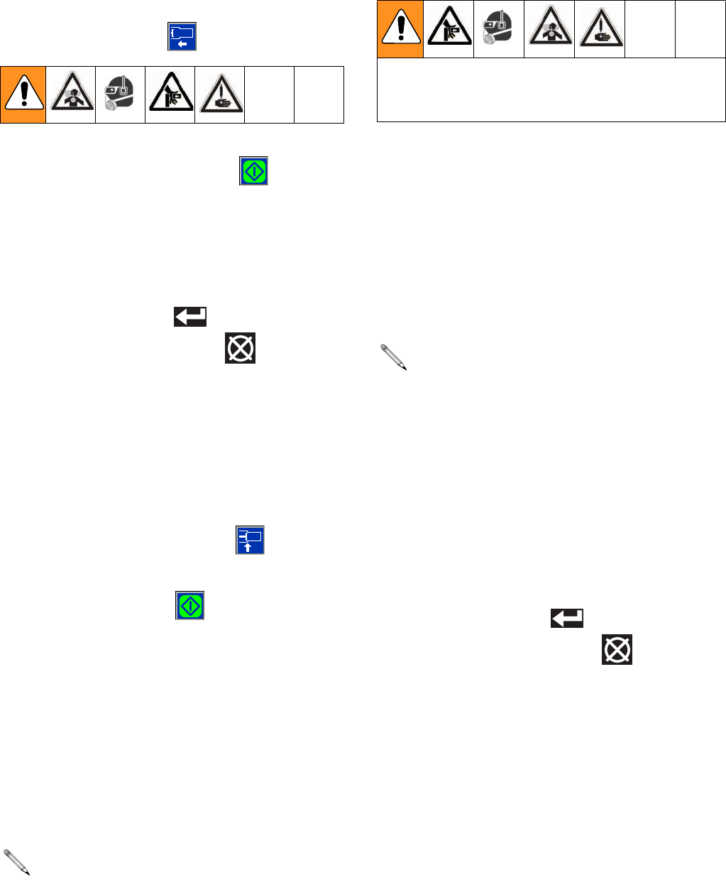
Retracted Piston Position
9. With air pressure applied to the machine, press the
Retract Piston button ( ).
10. Press the Start/Stop Shot button ( ). The piston
will fully retract and a number from 1250 to 1600 will
be displayed next to the Retract Piston button. If a
number outside of this range is displayed, ensure
the air cylinder air line connections are not switched
and that the linear position sensor is properly
installed.
11. Press the Enter button ( ) to accept the value or
press the Abort/Cancel button ( ) to keep the
previous value.
Engaged Piston Position
12. Use air pressure regulator to decrease air pressure
in the system to zero.
13. Place a clean waste container under the dispense
valve.
14. Press the Engage Piston button ( ).
15. With no air pressure in the system, press the
Start/Stop Shot button ( ).
16. Move the piston drive block until it just begins to
engage the cylinder using one of the following meth-
ods. No material should be dispensed.
Use Air Pressure to Move Piston Drive Block
a. Use the air pressure regulator to slowly
increase air pressure in the system until the pis-
ton drive block begins to extend and encounters
the cylinder entrance. A number from 2000 to
2400 will be displayed.
Manually Move the Piston Drive Block
a. Press down the system air pressure relief
switch (106).
b. Remove machine cover.
c. With no air pressure in the system manually
push the piston drive block until the piston
engages the cylinder and resists movement. A
number from 2000 to 2400 will be displayed.
d. Lift the system air pressure relief switch (106) to
enable system pressure.
17. Ensure there is no material in the waste container
under dispense valve. The piston block moved too
far and caused material to be dispensed if there is
material in the waste container. Go back to step 12
if the piston moved too far.
18. Press the Enter button ( ) to accept the value or
press the Abort/Cancel button ( ) to keep the
previous value.
Prepare Machine for Operation
19. Adjust the system air pressure regulator (105) to
increase air pressure to standard operating pres-
sure for your application.
20. Navigate to the Home screen. See Screen Naviga-
tion Diagram, page 16.
If a number outside of this range is displayed,
ensure the air cylinder air line connections are not
switched and that the linear position sensor is prop-
erly installed.
In the steps below, ensure pressure is off or piston
may activate and pinch fingers against machine
block.
If a number outside of this range is displayed,
ensure the air cylinder air line connections are not
switched and that the linear position sensor is prop-
erly installed.
Setup
312759R 39
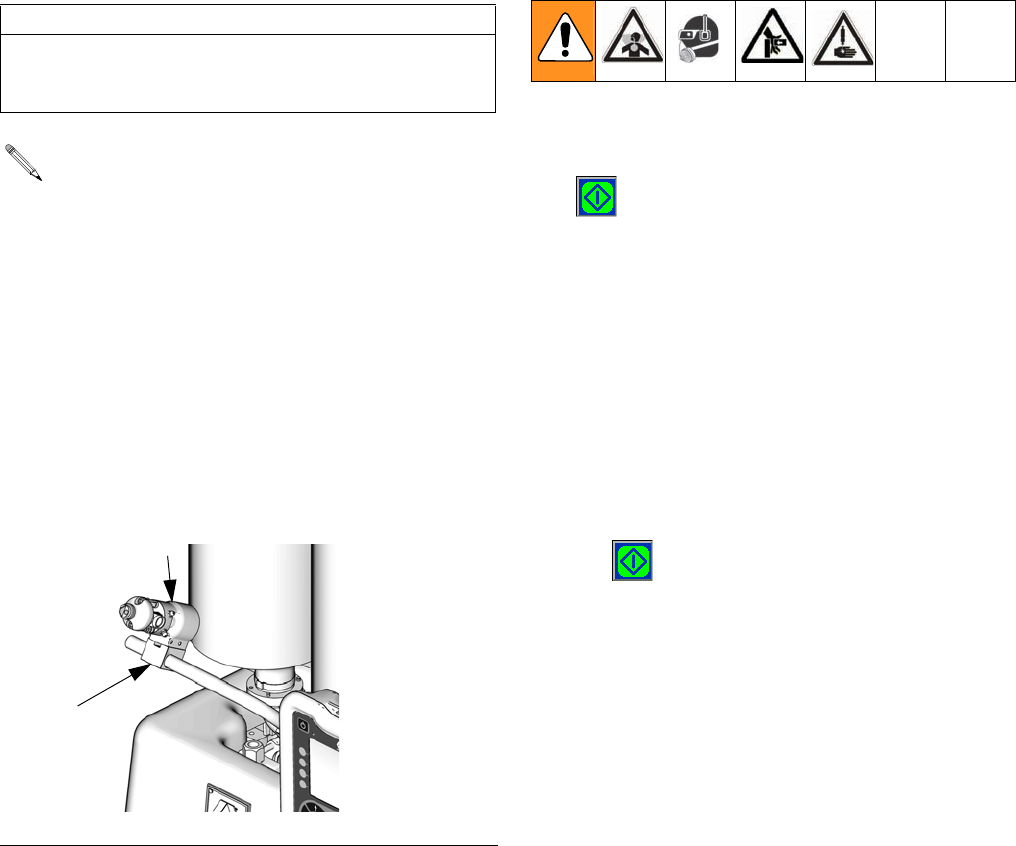
Prime the Dispense Head
1. Remove static mixer from the dispense head (102) if
installed.
2. Turn snuff-back adjustment knob (103) fully clock-
wise. This will prevent the dispense valve from clos-
ing between priming shots.
3. Use a 4 mm hex key to loosen the screws (102a)
holding the dispense head in place.
4. Rotate dispense head (102) so the tip is above the
fluid input hoses.
5. Use a 4 mm hex key to tighten screws (102a) hold-
ing dispense head in place.
6. Route the fluid hoses connected to the dispense
head so they are always below the dispense head.
This ensures any air in the hoses will travel to the
dispense head.
7. Navigate to the Home Screen. See Screen Naviga-
tion Diagram, page 16.
8. Select a large size shot.
9. Hold a waste container at the end of the dispense
head (102) and press the Start/Stop Shot button
( ) or the footswitch.
10. Repeat the previous step until no air comes out of
the dispense valve.
11. If phasing adjustments and ratio checking are not
required, use the following procedure to attach the
static mixer.
a. Attach the static mixer with the dispense head
pointed up.
b. Hold waste container at end of dispense
head (102) and press the Start/Stop Shot button
( ) or the footswitch.
c. Repeat the previous steps until static mixer has
been purged of air.
12. Use a 4 mm hex key to loosen screws (102a) hold-
ing dispense head in place.
13. Rotate dispense head back to normal dispensing
position.
14. Use a 4 mm hex key to tighten the screws (102a)
holding the dispense head in place.
15. Adjust snuff back to proper setting for operation.
See Adjust Dispense Valve Snuff Back on
page 42.
CAUTION
If the dispense head is not primed, chemical cross-
over may occur resulting in cured material in the dis-
pense head, hoses, and/or pumps.
See FIG. 24.
FIG. 24: Prime Dispense Head
102
ti12391a
102a
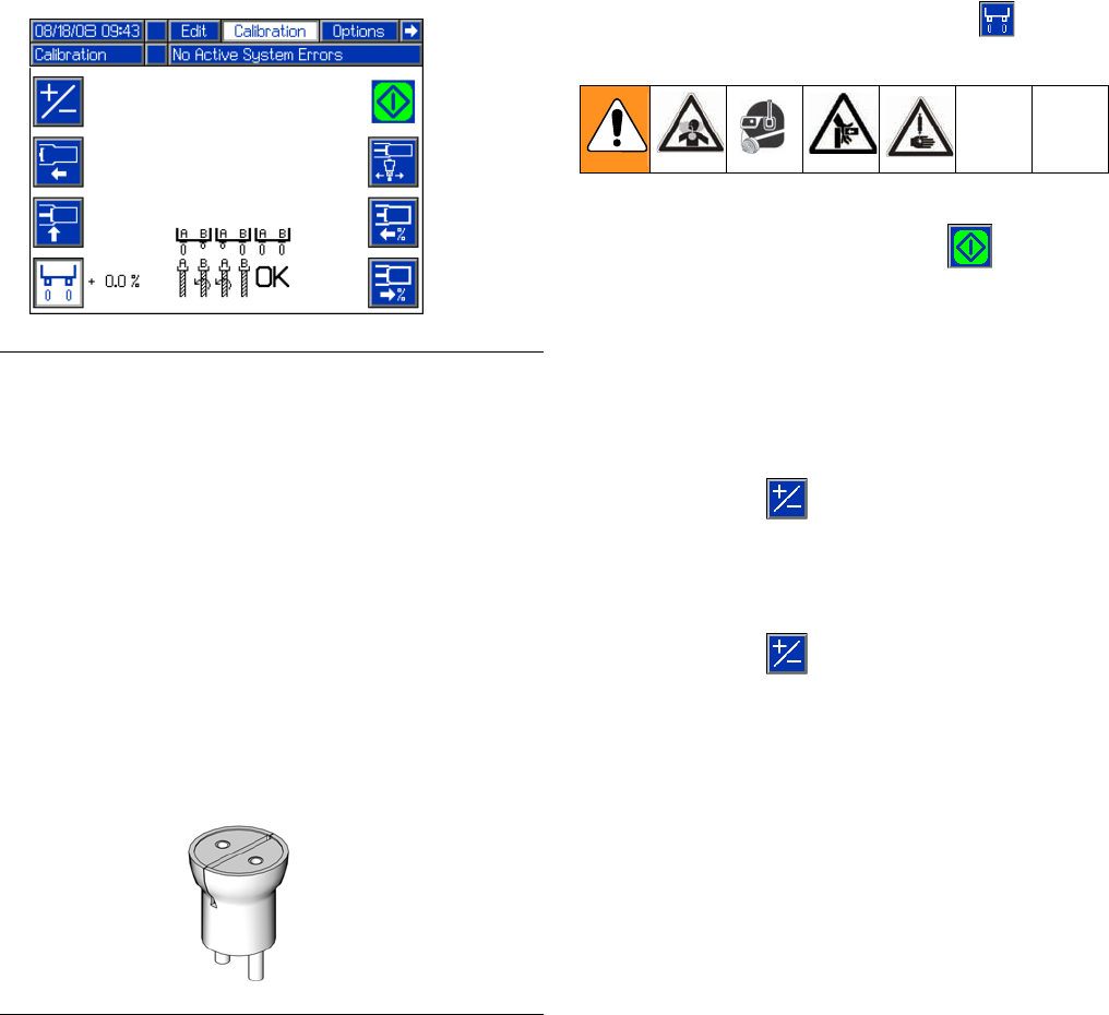
Setup
40 312759R
Phasing Adjustment
When the machine executes a shot, materials from
Tank A and Tank B enter the static mixer where they are
mixed and then dispensed. In order for the materials to
mix at the desired ratio, both materials must enter the
static mixer at the same time. The timing of the materials
entering the static mixer is dependent on the adjustment
of the phase adjustment screw for each piston.
Prepare Machine
1. Place a waste container under the dispense valve to
catch dispensed material.
2. Remove static mixer from dispense valve.
3. Install ratio check nozzle onto dispense valve.
4. If necessary, place a stand under ratio check nozzle
to support waste container close to nozzle.
5. Navigate to the Calibration screen. See Screen
Navigation Diagram, page 16.
Adjust Dispense Quantity
6. Press the Enter/Exit Phasing button ( ) to enter
phasing mode.
7. Press the Start/Stop Shot button ( ) or the foot-
switch to dispense a very small amount of material.
8. Adjust the displayed percentage if more than a cou-
ple drops of either material was dispensed or if no
material was dispensed from both sides.
• If too much material was dispensed, decrease
the phasing percentage. If necessary, use the
+/- button ( ) to switch the percentage from
positive to negative.
• If no material was dispensed, increase the dis-
played percentage. If necessary, use the
+/- button ( ) to switch the percentage from
negative to positive.
FIG. 25: Phasing
FIG. 26: Ratio Check Nozzle
ti12392a
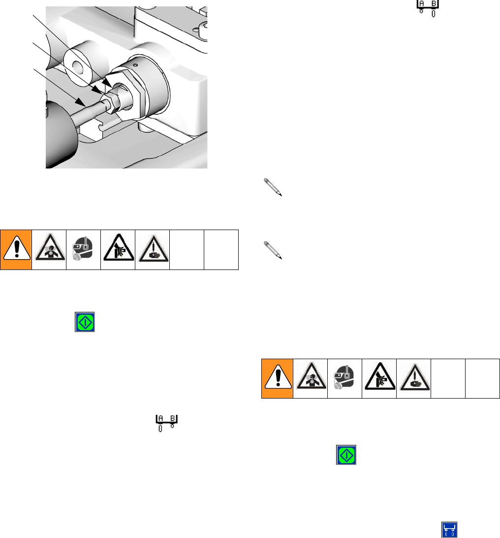
Setup
312759R 41
Adjust Phasing
9. Watch the dispense valve carefully to observe which
material is dispensed first. Press the Start/Stop
Shot button ( ) or the footswitch to dispense
material.
10. If the materials do not exit the dispense valve at the
same time adjust the piston Phase Adjustment
Screw (303) as follows.
• If the A side material exits the dispense nozzle
before the B side material ( ):
a. Use two 13 mm wrenches to break loose
the locking nut (302) from the phase adjust-
ment screw (303) on the B material side.
b. Hold the phase adjustment screw (303) sta-
tionary with a 13 mm wrench.
c. Use a 7 mm wrench to turn the piston
shaft (301) counterclockwise 1/4 turn or
less to move the B piston forward.
• If the B side material exits the dispense nozzle
before the A side material ( ):
a. Use two 13 mm wrenches to break loose
the locking nut (302) from the phase adjust-
ment screw (303) on the A material side.
b. Hold the phase adjustment screw (303) sta-
tionary with a 13 mm wrench.
c. Use a 7 mm wrench to turn the piston
shaft (301) counterclockwise 1/4 turn or
less to move the A piston forward.
11. Hold piston shaft (301) and phase adjustment
screw (303) in place with a 7 mm and 13 mm
wrench and tighten locking nut (302) against phase
adjustment screw with a 13 mm wrench.
12. Watch the dispense valve carefully to observe which
material is dispensed first. Press the Start/Stop
Shot button ( ) or the foot switch to dispense
material. If one material exits the dispense nozzle
before the other, go back to step 10.
Exit Calibration Mode
13. Press the Enter/Exit Phasing button ( ).
14. Navigate to the Home screen. See Screen Naviga-
tion Diagram, page 16.
301
302
303
Key:
301 Piston Shaft
302 Locking Nut
303 Phase Adjustment Screw
ti12389a
It is highly recommended that all of the phasing
adjustment be done to one side or the other; not
both.
Ensure the piston shaft and phase adjustment
screw do not rotate while tightening the locking
nut (302) in the following step.

Setup
42 312759R
Adjust Dispense Valve Snuff
Back
At the end of a shot, a small amount of material is drawn
back into the static mixer to prevent extra material from
being dispensed. If too much snuff back occurs air will
enter the static mixer and can travel up into the dispense
valve. If too little snuff back occurs the materials may
drip out of the static mixer and affect dispense quantity.
It is most efficient to adjust the snuff back while material
is dispensing but it can also be adjusted when there is
no air pressure in the system.
1. Navigate to the Home screen. See Screen Naviga-
tion Diagram, page 16.
2. Select a small size shot.
3. If a static mixer is not in place, install one then prime
the machine. See Prime the Dispense Head,
page 39.
4. Place a waste container under static mixer.
5. Press the Start/Stop Shot button ( ).
6. Inspect the tip of the static mixer for dripping mate-
rial or for air bubble traveling up the mixer.
7. Perform another shot and while dispensing adjust
the snuff-back adjustment knob (103) as follows.
• If an air bubble is moving up the mixer, turn
knob clockwise to decrease snuff back.
• If material is hanging from tip of mixer, turn knob
counterclockwise to increase snuff back.
8. Repeat step 7 until snuff back is adjusted as
desired.
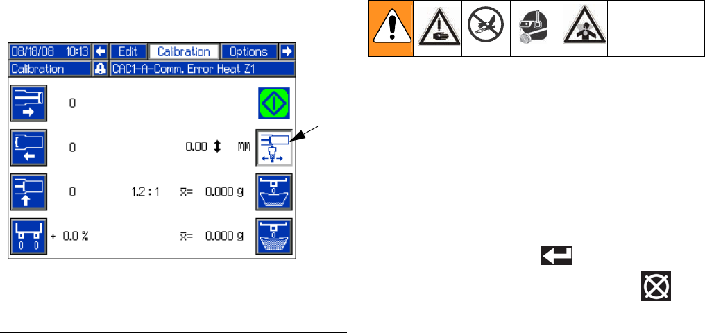
Setup
312759R 43
Adjust Open Dispense
Valve (ODV) Timing
When a shot is performed, the dispense valve needs to
open at a precise time for material to be dispensed
properly. If the dispense valve opens too early, material
may drain from the static mixer before the shot starts. If
the dispense valve opens too late, pressure may build in
the machine before the dispense valve opens causing
material to forcefully spray out of the mixer.
The Open Dispense Valve Timing should also be
adjusted for material viscosity. Thicker materials should
have the dispense valve open earlier and thinner materi-
als should have the dispense valve open later.
A positive value for Open Dispense Valve Timing indi-
cates the dispense valve will open after the piston is
engaged in the cylinder. A negative value indicates the
dispense valve will open before the piston is engaged in
the cylinder.
If a high positive number is entered for ODV timing, such
as 6.0 mm, the dispense valve may not open resulting in
the fluid stalling against the dispense valve. The fluid in
the hose lines will remain under pressure until the piston
is manually retracted using the Manual screen, see
Manual Screen on page 36.
1. Navigate to the Calibration screen. See Screen
Navigation Diagram, page 16.
2. Press the Adjust Open Dispense Valve Timing
button (FF).
3. Use the numeric keypad to enter a value for the
ODV Timing. Use the +/- key to switch from positive
to negative and negative to positive.
4. Press the Enter button ( ) to accept the new
value or press the Abort/Cancel button ( ) to
keep the previous value.
FIG. 27
Key:
FF Adjust Open Dispense Valve Timing
FF
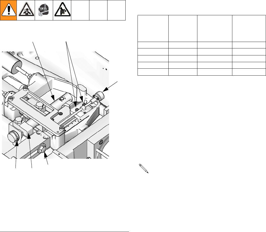
Setup
44 312759R
Calibrate Dispense Weight Ratio
(PR70v only)
The PR70v base unit can dispense volume ratios in the
range of 1:1 to 24:1. The range of A to B cylinder size
ratios is 1:1 to 12:1. The mechanical ratio arm multiplies
the constant cylinder size ratio by a range of 1:1 to 2:1
depending on the ratio arm adjustment.
Prepare Machine for Dispense Weight Ratio
Calibration
1. Verify the piston position is calibrated. See Piston
Position Calibration, page 37.
2. Verify the dispense head is properly primed. See
Prime the Dispense Head, page 39.
3. Verify the machine is properly phased. See Phas-
ing Adjustment, page 40.
4. Find the desired ratio arm setting from 1:1 to 2:1.
a. Divide the side A piston size by the side B pis-
ton size to get the piston volume ratio. For
example, if the A piston size is 960 mm2 and the
B piston size is 480 mm2 then 960 / 480 = 2.
b. Divide the desired dispensing volume ratio by
the piston volume ratio to get the desired ratio
arm setting. For example if the desired dispens-
ing volume ratio is 2.38:1 and the piston volume
ratio is 2:1 then 2.38 / 2 = 1.19.
FIG. 28: Ratio Adjustment
201
203
204
Key:
201 Ratio Adjustment Knob
202 Ratio Beam
203 Socket Head Cap Screws
204 Hex Head Cap Screw
205 Ratio Beam Guide
206 Ratio Beam Snap Ring
202
ti12390a
205
206
A Tube
Piston Size
(mm2)
B Tube
Piston Size
(mm2)
Minimum
Ratio by
Volume
(1:1 Position)
Maximum
Ratio by
Volume
(2:1 Position)
960 960 1:1 2:1
960 480 2:1 4:1
960 320 3:1 6:1
960 240 4:1 8:1
960 80 12:1 24:1
For this step, the desired volume ratio must be
known. Using the desired weight ratio will cause
calculation errors.
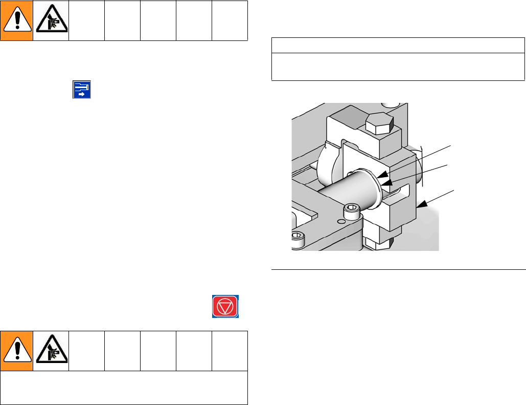
Setup
312759R 45
5. Change the mechanical ratio adjustment to the
desired setting (1.19 in the example) as follows.
a. Ensure the machine pistons are in the retracted
position.
b. Ensure the purge timer is off and the machine is
not in recirculation mode.
c. Use system air pressure regulator (105) to
decrease air pressure in the system to zero.
d. Navigate to the Manual screen. See Screen
Navigation Diagram, page 16.
e. Press the Extend Piston Command
button ( ).
f. Use the system air pressure regulator (105) to
slowly increase the air pressure until the ratio
beam (202) is parallel to the pump body.
g. Use system air pressure regulator (105) to
return the air pressure in the system to zero.
h. Press down the system air pressure relief
switch (106).
i. Close the shop ball valve supplying air to the
system.
j. Press the Machine Disable Mode key ( ).
k. Loosen the socket head cap screw (203) on the
adjustment clevis. See FIG. 28.
l. Loosen the hex head cap screws (204) on the
ratio adjustment pivot.
m. Turn the ratio adjustment knob (201) clockwise
to increase the ratio and counterclockwise to
decrease the ratio until the mechanical ratio arm
is set to the desired setting (1.19 in the exam-
ple).
n. Tighten the hex head cap screws (204) on the
ratio adjustment pivot.
o. Slide the ratio beam guide (205) so there is
approximately a 0.5 mm gap between the ratio
beam guide (205) and the snap ring (206)
shown in FIG. 29.
p. Tighten the socket head cap screw (203) on the
adjustment clevis.
q. Open the shop ball valve supplying air to the
system.
r. Lift up the system air pressure relief
switch (106).
s. Use system air pressure regulator (105) to
return to the standard operating air pressure for
your application.
Be sure the previous steps relieving system pres-
sure were completed before moving to the next step.
CAUTION
Damage to the ratio mechanism will result if the
proper clearance is not present.
FIG. 29: Ratio Beam Snap Ring
206
ti12630a
205
0.5 mm gap
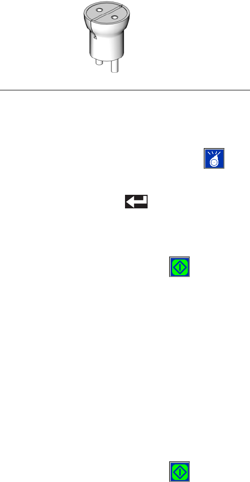
Setup
46 312759R
6. Navigate to the Home screen. See Screen Naviga-
tion Diagram, page 16.
7. Phase the machine. See Phasing Adjustment,
page 40.
Perform Weight Ratio Check Shot
8. Install ratio check nozzle onto dispense valve.
9. Place a waste container under the dispense valve to
capture any dispensed material.
10. Press the Select Operating Mode button ( )
repeatedly until Shot Mode is selected.
11. Press the Enter button ( ) to accept the new
operating mode.
12. Select a shot.
13. Press the Start/Stop Shot button ( ) or the
foot-switch to dispense material.
14. Discard the shot.
15. Label one scale as “A” and a second scale as “B”.
16. Label one new container as “A” and a second new
container as “B”.
17. Place container “A” on scale “A” and tare the scale.
Place container “B” on scale “B” and tare the scale.
18. Place container “A” under the A material output of
the ratio check nozzle. Place container “B” under
the B material output of the ratio check nozzle.
19. Press the Start/Stop Shot button ( ) or the
foot-switch to dispense material.
20. Place container “A” on scale “A” and note the
weight. Place container “B” on scale “B” and note
the weight.
21. Divide the weight of container “A” by the weight of
container “B” to get the weight ratio of the dispensed
materials.
22. Repeat steps 16 through 21 at least two more times
for an overall total of at least three ratio check shots,
or repeat as needed.
23. If the average A to B ratio of the dispensed materials
is too high or two low, adjust the mechanical ratio
arm as required by repeating steps 5 through 22
until the dispensing ratio is correct.
• If the A to B ratio is too high, turn the ratio
adjustment knob (201) counterclockwise to
adjust the mechanical ratio arm towards the 1:1
position.
• If the A to B ratio is too low, turn the ratio adjust-
ment knob (201) clockwise to adjust the
mechanical ratio arm towards the 2:1 position.
Secure Dispensing Ratio
24. Once the ratio check shots confirm the A to B dis-
pensing ratio is correct, tighten all screws holding
the ratio beam (202) in place.
a. Tighten the socket head cap screws (203) hold-
ing the ratio beam (202) in place to 140 in-lb
(15.8 N•m).
b. Tighten the hex head cap screw (204) holding
the ratio beam guide (205) in place to 350 in-lb
(39.5 N•m).
Prepare Machine for Operation
25. Remove ratio check nozzle and install static mixer or
night cap as necessary.
FIG. 30: Ratio Check Nozzle
ti12392a

Setup
312759R 47
Shot Calibration
To dispense accurate quantities of material, a few small
and large calibration shots must be performed. Once the
weights are entered, the machine will calculate an aver-
age weight for the small and large calibration shots.
Prepare for Calibration
1. Verify the piston position is calibrated. See Piston
Position Calibration, page 37.
2. Verify the dispense head is properly primed. See
Prime the Dispense Head, page 39.
3. Verify the machine is properly phased. See Phas-
ing Adjustment, page 40.
4. Verify the dispensing ratio is adjusted as needed.
See Calibrate Dispense Weight Ratio (PR70v
only), page 44.
5. Retrieve multiple waste containers.
6. Locate a weigh scale near the machine.
7. Install a static mixer.
8. Prime the dispense head. See Prime the Dispense
Head, page 39.
9. Clean the surface below static mixer of any debris or
materials that might cling to the waste container and
affect weight measurements.
10. Navigate to the Calibration screen. See Screen
Navigation Diagram, page 16.
Perform Small Calibration Shots
11. Press Small Calibration Shot button ( ) to enter
calibration mode.
12. Use the numeric keypad to enter the ratio arm set-
ting. Valid entries are 1.0 to 2.0 in 0.1 increments.
13. Press the Enter button ( ) to accept the value.
14. Weigh one clean waste container and tare the scale.
15. Place container under static mixer.
16. Press the Start/Stop Shot button ( ) or the foot-
switch to dispense material.
17. Weigh container.
18. Enter weight in grams using numeric keypad.
19. Press the Enter button ( ) to accept the number
or press the “0” button on the numeric keypad
repeatedly to clear out the entry then re-enter.
20. Repeat steps 14 through 19 as needed. Graco rec-
ommends repeating steps 14 through 19 at least
four more times. The machine will automatically cal-
culate the average weight of the calibration shots.
21. Press Small Calibration Shot button ( ) to exit
calibration mode.
Perform Large Calibration Shots
22. Press Large Calibration Shot button ( ) to enter
calibration mode.
23. Weigh one clean waste container and tare the scale.
24. Place container under static mixer.
25. Press the Start/Stop Shot button ( ) or the foot-
switch to dispense material.
26. Weigh container.
27. Enter weight in grams using numeric keypad.
28. Press the Enter button ( ) to accept the number
or press the “0” button on the numeric keypad
repeatedly to clear out the entry then re-enter.
29. Repeat steps 23 through 27 as needed. Graco rec-
ommends repeating steps 23 through 27 at least
four more times. The machine will automatically cal-
culate the average weight of the calibration shots.
30. Press the Large Calibration Shot button ( ) to
exit calibration mode.
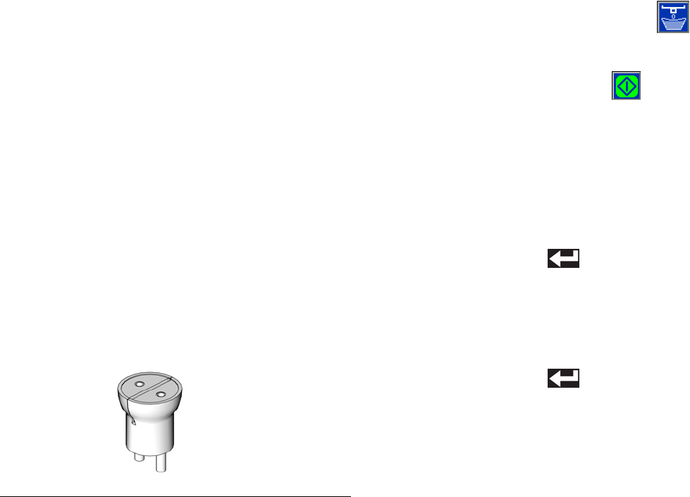
Setup
48 312759R
Flow Meter Calibration
Prepare for Calibration
1. Verify the piston position is calibrated. See Piston
Position Calibration, page 37.
2. Verify the dispense head is properly primed. See
Prime the Dispense Head, page 39.
3. Verify the machine is properly phased. See Phas-
ing Adjustment, page 40.
4. Verify the dispensing ratio is adjusted as needed.
See Calibrate Dispense Weight Ratio (PR70v
only), page 44.
5. Retrieve multiple waste containers.
6. Locate a weigh scale near the machine.
7. Clean the surface below static mixer of any debris or
materials that might cling to the waste container and
affect weight measurements.
8. Install ratio check nozzle onto dispense valve.
9. Prime the dispense head. See Prime the Dispense
Head, page 39.
10. Navigate to the Flow Meter Calibration screen. See
Screen Navigation Diagram, page 16.
Perform Flow Meter Calibration Shot
11. Place a waste container under the dispense valve to
capture any dispensed material.
12. Label one scale as “A” and a second scale as “B”.
13. Label one new container as “A” and a second new
container as “B”.
14. Place container “A” on scale “A” and tare the scale.
Place container “B” on scale “B” and tare the scale.
15. Place container “A” under the A material output of
the ratio check nozzle. Place container “B” under
the B material output of the ratio check nozzle.
16. Press the Flow Meter Calibration button ( ) to
enter calibration mode.
17. Press the Start/Stop Shot button ( ) or the
foot-switch to dispense material.
18. Place container “A” on scale “A” and note the
weight. Place container “B” on scale “B” and note
the weight.
19. Enter the A material weight in grams using numeric
keypad.
20. Press the Enter button ( ) to accept the number
or press the “0” button on the numeric keypad
repeatedly to clear out the entry then re-enter.
21. Enter the B material weight in grams using numeric
keypad.
22. Press the Enter button ( ) to accept the number
or press the “0” button on the numeric keypad
repeatedly to clear out the entry then re-enter.
23. Repeat the previous steps as desired for additional
accuracy. The display module will automatically cal-
culate an average weight for each material.
Dispense Verification
See Dispense Check Options, Screen #4, page 31.
FIG. 31: Ratio Check Nozzle
ti12392a

Setup
312759R 49
External Control Interface Setup
The external control interface allows an external
machine to control the PR70. The external machine can
use Connector #1 to send dispense request and abort
commands. Also, Connector #1 indicates to the external
machine whether the PR70 is ready to dispense.
Connector #2 is used to select a shot number. See FIG.
33 for connector location on the PR70.
Ready-Output Status Line
The Ready-Output status line (“READY-OUTPUT” in
FIG. 32, Connector #1, Pin #2) is a signal provided to the
external control. The line indicates whether a shot or
dispense request will be accepted by the machine. The
output of the Ready-Output status line is a “high”
+24 VDC signal when the system is ready to dispense.
The output is a “low” +15 VDC signal when the system
is not ready to dispense. See FIG. 34 on page 52 for a
sample timing diagram.
The following conditions will make the machine not
ready to accept a dispense request.
• Dispensing in progress.
• User is programming the display module.
• Active error code that has not been acknowledged.
• Auto-Sequencing in progress.
FIG. 32: External Control Interface Electrical Diagram
Connector #2
Connector #1
4
5
1
3
2
4
5
1
3
2
Customer Supplied
Dry Contact/Relay
Customer Supplied
Dry Contact/Relay
SHOT SEL - BIT 0
SHOT SEL - BIT 3
SHOT SEL - BIT 2
COMMON
SHOT SEL - BIT 1
SHOT REQUEST - INPUT
FAULT OUTPUT
INTERRUPT - CAN - REQ - INPUT
COMMON
READY - OUTPUT
Brown
Gray
Black
Blue
White
Brown
+24 VDC
+24 VDC
Gray
Black
Blue
White
NOTE: Connector #1 is for use with all systems.
NOTE: View shown is looking at pins on end of cable.
NOTE: Connector #2 is for use with systems with an Advanced
Display Module only.
NOTE: View shown is looking at pins on end of cable.
FIG. 33: External Control Connectors
Connector #1
Connector #2
ti12583a

Setup
50 312759R
Fault-Output Status Line
The Fault-Output status line (“FAULT-OUTPUT” in FIG.
32, Connector #1, Pin #5) indicates whether there is an
active error. Active errors typically stop system opera-
tion. After using the display module to acknowledge the
error, normal operation will be allowed.
The output of the Fault-Output status line is a “high”
+24 VDC signal when an active error exists. The output
is a “low” +15 VDC signal when there is not an active
error. See FIG. 34 on page 52 for a sample timing dia-
gram.
Dispense Request Line
The Dispense Request line (“Shot Request” in FIG. 32,
Connector #1, Pin #1) is used to request a shot. The
Dispense Request line operates the same as the
machine foot switch and the Start/Stop Shot
button ( ). When not in Operator mode and with a
“high” Ready-Output signal, generate a short active Dis-
pense Request signal to request a shot to begin. During
dispensing, generate a short active signal in the Dis-
pense Request line to abort the shot.
To generate an active Dispense Request signal, the
external control will need to ground the Dispense
Request line to the Return line (Connector #1, Pin #3)
for 0.175 seconds to create a “low” signal. Remove the
line from the Return line to end the active signal. See
FIG. 34 on page 52 for a sample timing diagram.
If the active signal is generated when the system is in
programming mode or generating an error code, the
shot request will be ignored.
If the active signal is sent during execution of a pause
when in Auto-Sequencing, the machine will abort the
pause timer and begin dispensing the next shot in the
sequence.
If the active signal is sent during execution of a shot in a
sequence, the machine will abort the shot and will incre-
ment to the next shot in the sequence after the pistons
fully retract. If the sequence is in auto-sequencing, the
sequence pause timer will then begin.
If Operator (Manual) mode is selected, the machine will
dispense while the active signal is sent. When the active
signal stops, the machine will stop dispensing. If the pis-
ton Auto-Retract option is enabled on the System
Options screen, the piston will retract when the machine
stops dispensing. See FIG. 17 on page 30. If the Piston
Auto-Retract is disabled, the machine will stop dispens-
ing and stall the pumps against the dispense valve. If
the pump is more than 80% into the metering tube, it will
automatically retract regardless of whether Piston
Aut-Retract is enabled.
Interrupt - Cancel Line
The Interrupt - Cancel line (“INTERRUPT - CAN - REQ -
INPUT” in FIG. 32, Connector #1, Pin #4) is used to
abort a shot or reset a sequence. If an active signal is
sent during a sequence, any active dispensing will be
aborted and the sequence position will be reset to the
first non-zero shot in the sequence.
To generate an active Interrupt - Cancel signal, the
external control will need to ground the Interrupt - Can-
cel line to the Return line (Connector #1, Pin #3) for
0.175 seconds to create a “low” signal. Remove the line
from the Return line to end the active signal.
For system software versions 1.06.007 or later, if the
Interrupt - Cancel line is held “low” the machine will be
disabled and will not dispense.

Setup
312759R 51
Shot Number Selection Lines
The external control interface has four lines used to
select a shot number (“SHOT - SEL - BIT” lines in FIG.
32, Connector #2, Pins #1, 2, 4, 5). The default for each
line is a “high” +24 VDC output. To select a shot, the
external control will need to ground a certain combina-
tion of lines to the Return line (Connector #2, Pin #3) for
at least 0.100 seconds to create a “low” signal for each
line. Each combination refers to one shot number from
Shot #1 to Shot #15. If all lines are “high” the shot
selected on the display module is used. See the follow-
ing table. See FIG. 34 on page 52 for a sample timing
diagram.
For system software versions 1.06.007 or later, the Shot
Number Selection lines cannot be used to select invalid
or undefined shot numbers. Attempting to select an
invalid or undefined shot number will be rejected.
Shot
Number
Selected
SHOT -
SEL -
BIT0
(Conn. #2,
Pin #1)
SHOT -
SEL -
BIT1
(Conn. #2,
Pin #2)
SHOT -
SEL -
BIT2
(Conn. #2,
Pin #4)
SHOT -
SEL -
BIT3
(Conn. #2,
Pin #5)
None /
Display
Module
selec-
tion.
High High High High
1Low High High High
2High
Low High High
3Low Low High High
4 High High Low High
5Low High Low High
6High
Low Low High
7Low Low Low High
8 High High High Low
9Low High High Low
10 High Low High Low
11 Low Low High Low
12 High High Low Low
13 Low High Low Low
14 High Low Low Low
15 Low Low Low Low
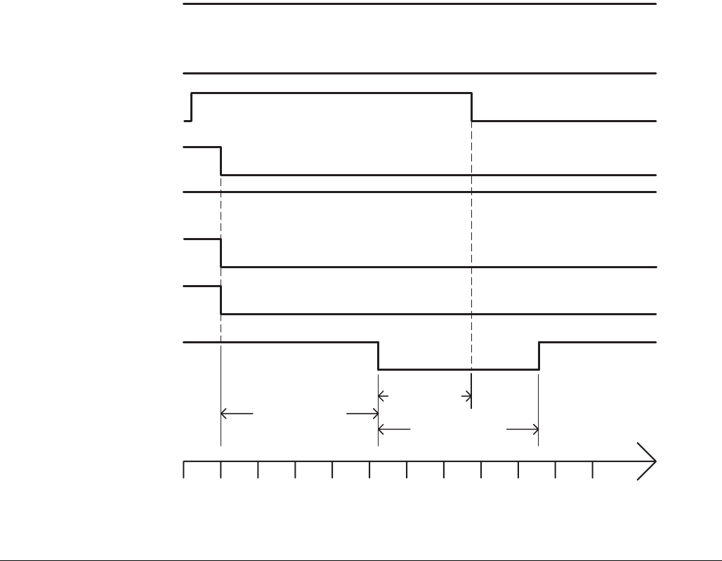
Setup
52 312759R
External Control Interface Timing
The following timing diagram illustrates changing the
shot number to Shot #13 then dispensing that shot.
FIG. 34: External Control Timing Diagram
Ready-Out Status
SHOT-SEL-BITO
SHOT-SEL-BIT2
SHOT-SEL-BIT3
Shot Request
SHOT-SEL-BIT1
Fault-Out Status
100 mS
170 mS
170 mS
0 40 80 120 160 200 240 280 320 360 400 440
TIME (milliseconds)
Interrupt - Cancel
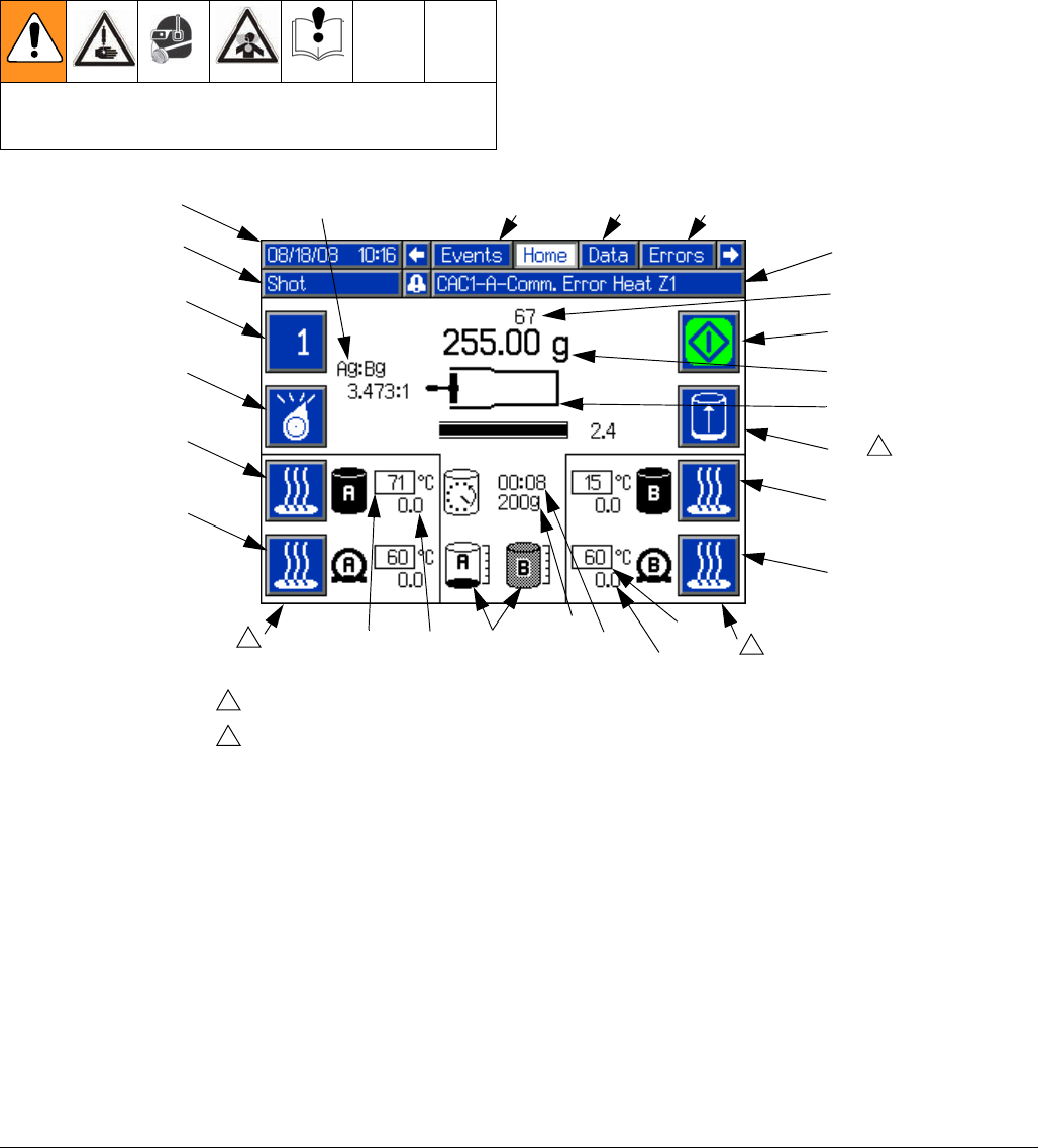
Operation
312759R 53
Operation
Operation Screens
Home screen
Read all manufacturer’s warning and material MSDS
to know the specific hazards of the materials used.
FIG. 35
BA
Key:
BA Active Shot/Sequence
BB Select Operating Mode
BC Side A Blanket Heater On/Off
BD Side A Hose Heater On/Off
BE Side B Blanket Heater On/Off
BF Side B Hose Heater On/Off
BG Start/Stop Shot
BJ Date and Time
BK Operating Mode Name
BL Alarm Status
BM Shot/Sequence Count
BN Active Shot Weight
BP Pump Position
BR Tank Fluid Temperature Setpoint
BS Tank Fluid Temperature
BT Hose Heater Temperature Setpoint
BT1 Hose Heater Temperature
BU Tank Fluid Level Status
BV Purge Timer Delay Status
BW Purge Timer Shot Size
BX Initiate Manual Auto-Refill
BY Active Screen Name
BZ Adjacent Screen Names
B1 A to B Weight Ratio for Previous
Dispense
BK BL
BU
Temperature status will only be displayed if heaters are installed and enabled.
Only visible if Auto-Refill is installed and the High Level Sensors option on the
Fluid Options Screen is set to an option other than Disabled. See Fluid Options,
Screen #1, page 26.
1
2
BJ
BB
BC
BD
BG
BE
BF
BP
BN
BM
11
BW
BV BT
BS
BR
BX 2
BY BZ
BZ
BT1
B1
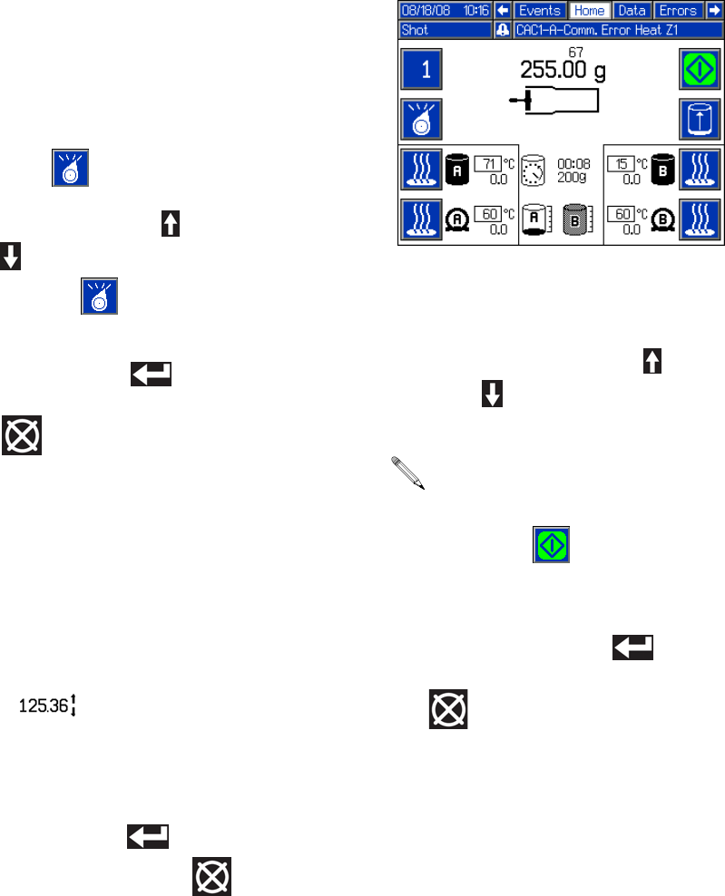
Operation
54 312759R
Change Operating Mode
The available operating modes are Shot, Sequence,
Operator (Manual), Recirculation, and Disabled mode.
The active operating mode name will be shown on the
Home screen under the date and time. See FIG. 35 on
page 53.
1. From the Home screen, press the Select Operating
Mode button ( ).
2. Press the Up Arrow button ( ) or the Down Arrow
button ( ), or repeatedly press the Select Operat-
ing Mode button ( ) to scan through the operat-
ing modes.
3. Press the Enter button ( ) to accept the
selected operating mode or press the Abort/Cancel
button ( ) to keep the current mode.
Change Active Shot Size Definition from
Home Screen
1. Select Shot or Sequence Mode. See Change Oper-
ating Mode, page 54.
2. Select the shot to change.
3. Press and hold the Shot/Sequence button (BA) for
four seconds. Arrows will be displayed next to the
shot size ( ) indicating that the value may be
changed.
4. Use the numeric keypad or the arrow buttons to
change the shot size.
5. Press the Enter button ( ) to accept the value or
press the Abort/Cancel button ( ) to keep the
previous value.
Shot Mode Operation
Change Active Shot
1. Press the Active Shot/Sequence button (BA).
2. Press the Up Arrow button ( ) or the Down Arrow
button ( ) or use the numeric keypad to enter the
shot number.
3. Press the Enter button ( ) to accept the new
Shot Number or press the Abort/Cancel button
( ) to keep the previous Shot Number.
When typing in the shot number using the numeric
keypad, a shot with a zero quantity may be entered.
The machine will give an error when the Start/Stop
Shot button ( ) is pressed if a zero-quantity
shot is selected.
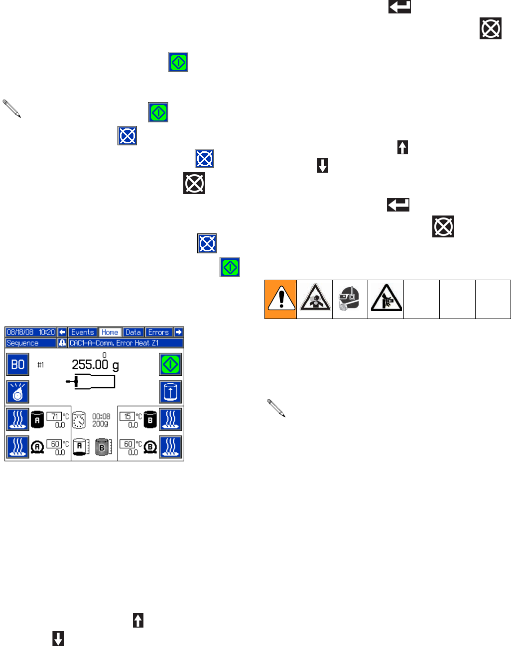
Operation
312759R 55
Perform a Shot
1. Select Shot Mode. See Change Operating Mode,
page 54.
2. Press the Start/Stop Shot button ( ) to start a
shot.
Sequence Mode Operation
To change the setup of a sequence navigate to Edit
Screens #2-#5. See Screen Navigation Diagram,
page 16.
Change Active Sequence
1. Select Sequence Mode. See Change Operating
Mode, page 54.
2. Press and hold the Active Shot/Sequence
button (BA) for three seconds.
3. Use the Up Arrow button ( ) and the Down Arrow
button ( ) to select the desired sequence. Only
non-zero sequences will be available for selection.
4. Press the Enter button ( ) to accept the new
sequence or press the Abort/Cancel button ( )
to keep the previous sequence.
Change Active Position in Sequence
1. Select Sequence Mode. See Change Operating
Mode, page 54.
2. Press the Active Shot/Sequence button (BA).
3. Use the Up Arrow button ( ) and the Down Arrow
button ( ) to select the desired position in the
sequence.
4. Press the Enter button ( ) to accept the number
or press the Abort/Cancel button ( ) to keep the
current number.
Perform a Sequence
1. Select Sequence Mode. See Change Operating
Mode, page 54.
2. Select the desired sequence.
The Start/Stop Shot button ( ) changes to the
Abort/Cancel button ( ) during the shot. Press
the Abort/Cancel button on the screen ( ) or the
Abort/Cancel button on the keypad ( ) to can-
cel the shot if necessary.
When the shot is complete or if the shot is aborted,
the Abort/Cancel button on the screen ( )
changes back to the Start/Stop Shot button ( ).
If Auto-Sequencing is enabled on the Edit Screens
for the Active Sequence, the machine will automati-
cally perform all shots in that sequence when the
Start/Stop button is pressed. See Edit Screens,
page 22.
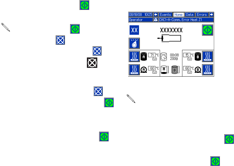
Operation
56 312759R
3. Press the Start/Stop Shot button ( ) to start a
shot.
4. If Auto-Sequencing is not enabled for the Active
Sequence the next shot in the sequence will be
selected. Press the Start/Stop Shot button ( ) to
start the shot.
5. Repeat step 4 until the sequence has been com-
pleted.
Operator (Manual) Mode Operation
Dispense
1. Select Operator (Manual) mode. See Change
Operating Mode, page 54.
2. Press and hold the Start/Stop Shot button ( ) to
begin dispensing.
3. Release the Start/Stop Shot button ( ) to stop
dispensing.
The Start/Stop Shot button ( ) changes to the
Abort/Cancel button ( ) during the shot. Press
the Abort/Cancel button on the screen ( ) or the
Abort/Cancel button on the keypad ( ) to can-
cel the shot if necessary.
When the shot is complete or if the shot is aborted,
the Abort/Cancel button on the screen ( )
changes back to the Start/Stop Shot button ( ).
Operator (Manual) Mode does not use the pre-
defined shots or sequences.
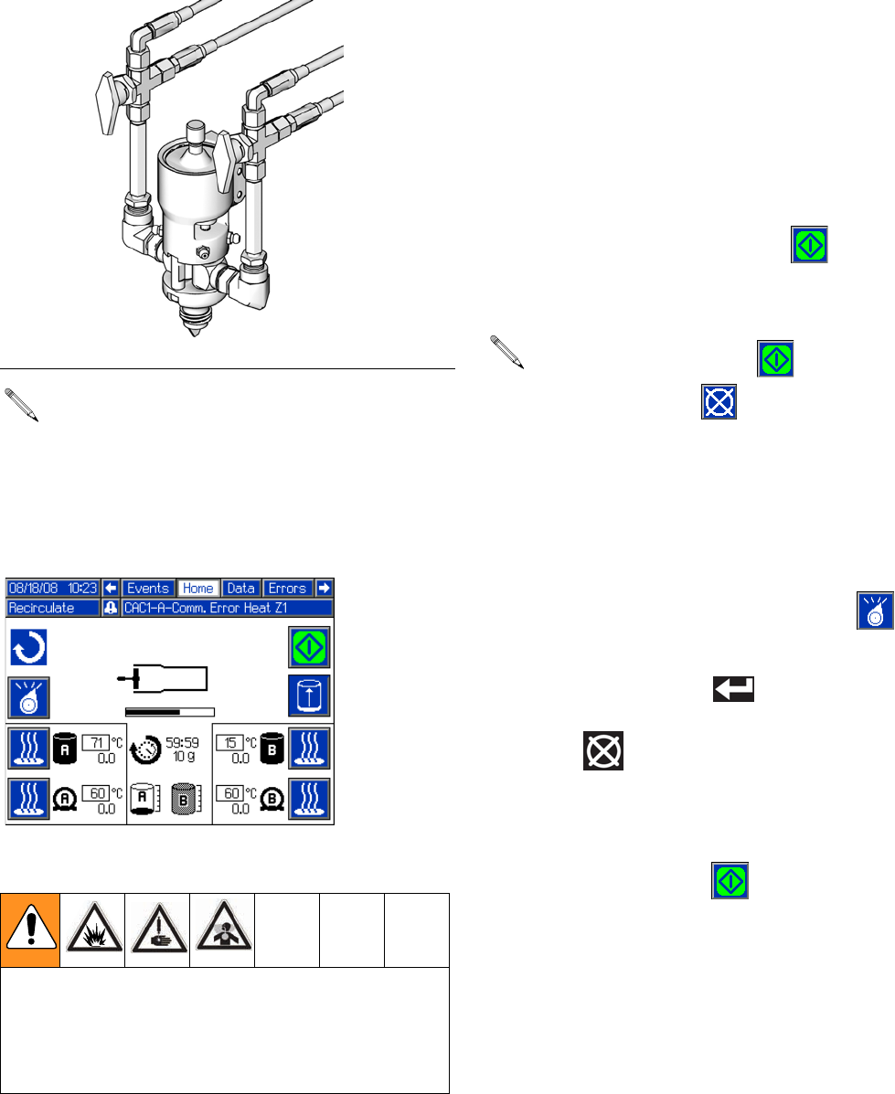
Operation
312759R 57
Recirculation Mode Operation
Recirculate Materials
1. Turn both 3-way ball valves at the dispense valve so
materials will flow back to tank.
2. Ensure system air pressure is at the standard oper-
ating setting.
3. Navigate to the Fluid Options Setup Screen. See
Screen Navigation Diagram on page 16.
4. Configure the shot size, timer duration, and alarm
point, then enable the Recirculation Timer. See
Fluid Options, Screen #1 on page 26.
5. Navigate to the Home screen. See Screen Naviga-
tion Diagram on page 16.
6. Press the Start/Stop Shot button ( ) to begin the
recirculation cycle and take the first recirculation
shot.
Stop Recirculation, If Necessary
7. Press the Select Operating Mode button ( )
repeatedly to scan through operating modes.
8. Press the Enter button ( ) to accept the
selected operating mode or press the Abort/Cancel
button ( ) to keep the current mode.
9. If changing modes is cancelled, the machine will
remain in recirculation mode but the recirculation
cycle is stopped. To restart recirculation, press the
Start/Stop Shot button ( ).
10. When Recirculation mode is stopped, turn the 3-way
ball valves at the dispense valve so materials will
flow out of the dispense head.
FIG. 36: Recirculation Valves
Recirculation mode requires that one 3-way ball
valve is installed for each material line. The ball
valve must be installed at the dispense head and
have fluid lines going from the ball valve back to the
tank. See FIG. 36.
In Recirculation mode, the dispense valve is always
closed.
When Recirculation mode is enabled, both recircula-
tion ball valves must be turned to return material
back to the tank. Only turning one valve may result in
a pressure imbalance exceeding the machine’s maxi-
mum working pressure.
ti12392a
The Start/Stop Shot button ( ) changes to the
Abort/Cancel button ( ) while the recirculation
shot is dispensing. Press the Abort button to cancel
that shot. Recirculation mode will remain active and
another recirculation shot will occur at the expira-
tion of the timer.
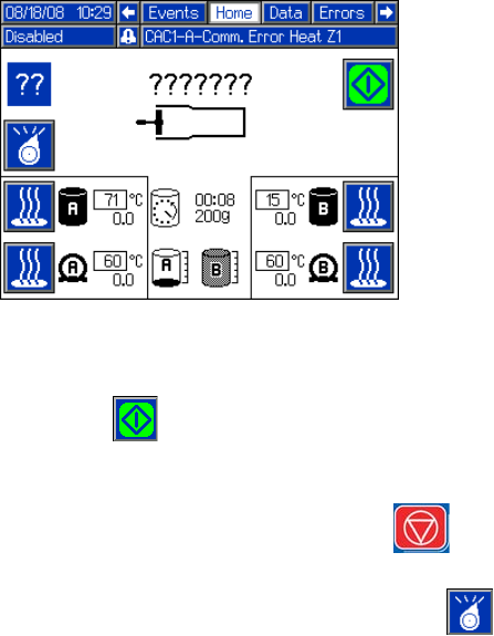
Operation
58 312759R
Disabled Mode Operation
The machine will not dispense in this mode. All outputs
to the solenoid valves are disabled and the Start/Stop
Shot button ( ) is inactive. Heat controls remain
active.
Pressing the Machine Disable Mode key ( ) will
enter Disabled Mode and disable heat. Select Disabled
mode using the Select Operating Mode button ( ) to
enter Disabled Mode without disabling heat.
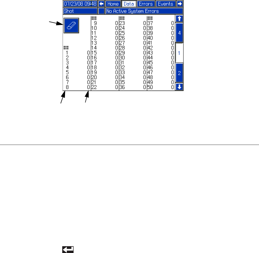
Operation
312759R 59
Data Screens
The data screens show the shot counters for all shots
and shot sequences. Data screen #1 shows the shot
counters for all shots. Data screens #2-#5 show the shot
counters for sequences A through G, with two
sequences shown per screen.
Reset Shot and Sequence Counters
1. Navigate to the correct Data Screen. See Screen
Navigation Diagram on page 16.
2. Press the Enter/Exit Screen button (CC).
3. Use the arrow keys to navigate to the counter to be
reset.
4. Press the Enter button ( ) to erase the selected
counter.
5. Repeat steps 3 and 4 as necessary to erase other
counters on the same screen.
6. Press the Enter/Exit Screen button (CC) to exit the
screen.
FIG. 37
Key:
CA Shot Number Column
CB Shot Counter Column
CC Enter/Exit Screen
CB
CC
CA
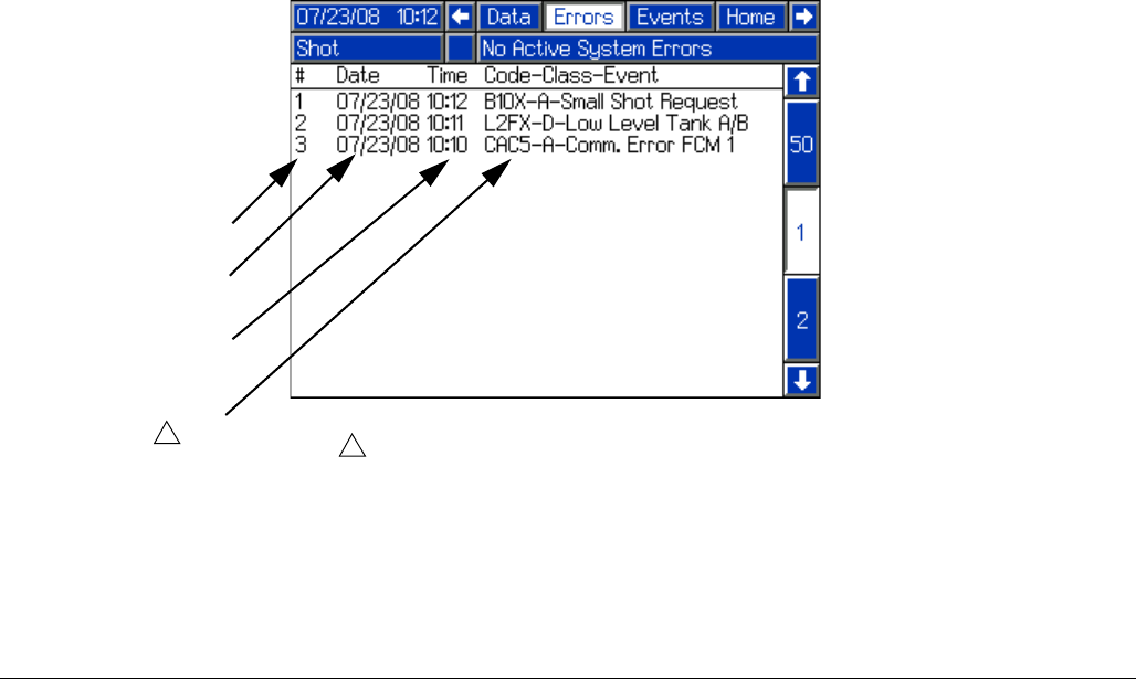
Operation
60 312759R
Error Screens
The Errors Screen tracks all of the errors that have
occurred on the machine. The latest error will appear at
the top of the list with date, time, and code-class-event
information. For more information on the
code-class-event information, see Troubleshooting
section, page 69.
FIG. 38
DA
Key:
DA Error Number
DB Date Error Occurred
DC Time Error Occurred
DD Error Details
DB
DC
DD
See Troubleshooting section, page 69.
1
1
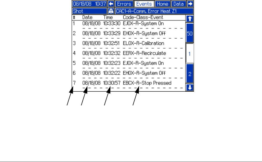
Operation
312759R 61
Events Screen
The Events Screen shows a history of events for the
machine with details of the event including date and
time. The following is a list of events tracked on the
Events Screen.
• System Powered On
• System Powered Off
•Shot
• Purge Shot
• Stop Button Pressed
• System Calibrated
• Recirculation Mode entered
FIG. 39
NA
Key:
NA Event Number
NB Date Event Occurred
NC Time Event Occurred
ND Event Details
NB NC ND
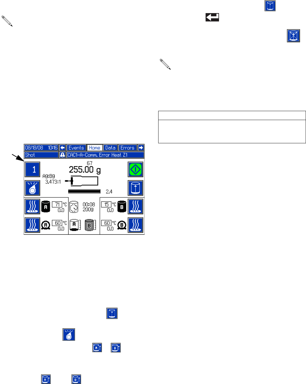
Operation
62 312759R
Auto-Refill
With Level Sensors installed, Auto-Refill can be used.
There are multiple Auto-Refill modes ranging in function.
For details on the different modes, see Fluid Options,
Screen #1 on page 26.
The tank icons on the Home Screen display the status of
each tank.
In all Auto-Refill modes other than Manual Auto-Refill,
the machine automatically performs the appropriate
functions.
Manually Initiate Auto-Refill
This procedure can be used to initiate auto-refill if Man-
ual Auto-Refill, High Level Auto-Refill, Empty Auto-Refill,
or Accumulator mode is enabled. See Fluid Options,
Screen #1 on page 26 for a description of each
Auto-Refill mode.
1. Navigate to the Home Screen. See Screen Naviga-
tion Diagram on page 16.
2. Press the Initiate Auto-Refill button ( ). The
Active Shot/Sequence button (BA) and Select Oper-
ating Mode button ( ) will each change to the
Auto-Refill Tank Select button ( or ) if a valid
Auto-Refill mode is enabled for both tanks.
3. Press the appropriate Auto-Refill Tank Select button
or buttons ( and/or ) to select the tanks to
refill.
4. Press the Initiate Auto-Refill button ( ) or the
Enter button ( ) to confirm.
5. If necessary, press the Abort/Cancel button ( )
to cancel auto-refill.
See Fluid Options, Screen #1 on page 26 for a
description of each Auto-Refill mode.
BA
If an auto-refill is aborted or times out, the software
will not initiate a new auto-refill until a manually initi-
ated auto-refill has completed. To complete a man-
ually initiated auto-refill after an aborted or timed
out auto-refill, restart at step 2.
CAUTION
If an auto-refill is stopped and not restarted as
described in the previous note, the pumps may be run
dry and chemical crossover at the valve may occur.
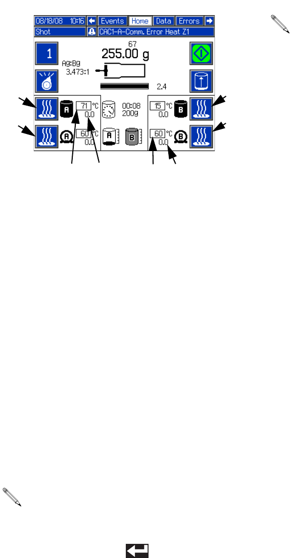
Operation
312759R 63
Temperature Control
The Tank Fluid Temperature Setpoint (BR), Tank Fluid
Temperature (BS), Hose Heater Temperature (BT1),
and Hose Heater Temperature Setpoint (BT) display the
status of the each of the options. To turn the Tank Blan-
ket Heaters or Hose Heaters on or off, press the Tank or
Hose Heater On/Off button (BC, BD, BE, BF). See Heat
Options, Screen #2 on page 28 for more information on
temperature control setup.
Change Heater Temperature Setpoint from Home
Screen
Changing the Heater Temperature Setpoint can be done
from the Setup screens or from the Home Screen. To
change the temperature setpoint for any of the installed
tank or hose heaters from the Home Screen, perform
the following steps.
1. Press and hold the Tank or Hose Heater On/Off
button (BC, BD, BE, BF) for four seconds. The tem-
perature setpoint box will invert colors.
2. Use the numeric keypad to enter the new tempera-
ture setpoint.
3. Press the Enter button ( ) to accept the new
value.
Purge Timer
The Purge Timer automatically issues a shot after the
machine has been idle a set amount of time to clear the
static mixer of partially cured material. After a shot is fin-
ished, the clock counts down from the value set in the
setup screens. The Purge Alarm will sound prior to the
purge shot. When the timer reaches the Purge Alarm
time, the Purge Alarm will sound until the timer reaches
zero or the user issues a shot. When the timer reaches
00:00, the machine will issue a shot equal to the amount
set for the purge timer shot size and that is shown under
the timer. The timer will reset and the process will
repeat.
The maximum allowable set point is 160oF (71oC)
and the minimum is 60oF (15oC).
BC
BD
BE
BF
BT1
BT
BSBR
Purge Timer settings can be changed from the
Fluid Options Setup Screen, see page 26.
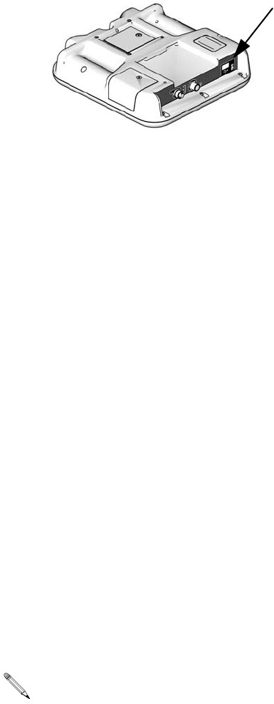
USB Data
64 312759R
USB Data
USB Logs
During operation, PR70 stores system and performance
related information to memory in the form of log files.
PR70 maintains two log files: error logs and event logs.
Follow the Download Procedure on this page to
retrieve log files.
Error Log
The error log file name is 1-ERROR.CSV and is stored
in the DOWNLOAD folder.
The error log maintains a record of the last 1,000 errors.
• Error occurrence date
• Error occurrence time
• Error description
Event Log
The event log file name is 2-EVENT.CSV and is stored
in the DOWNLOAD folder.
The event log maintains a record of the last 10,000
events.
An event entry is stored on the completion of an event.
The following data, when applicable, is stored:
• Event date
• Event time
• Event description
• Shot Weight (grams)
• Dispense duration (seconds)
• Material A temperature
• Material B temperature
• Temperature units
Download Procedure
1. Insert USB flash drive into USB port.
2. The menu bar and USB indicator lights indicate that
the USB is downloading files. Wait for USB activity
to complete.
3. Remove USB flash drive from USB port.
4. Insert USB flash drive into USB port of computer.
5. The USB flash drive window automatically opens. If
it does not, open USB flash drive from within Win-
dows® Explorer.
6. Open Graco folder.
7. Open system folder. If downloading data from ore
than one system, there will be more than one folder.
Each folder is labeled with the corresponding serial
number of the ADM (The serial number is on the
back of the ADM.)
8. Open DOWNLOAD folder.
9. Open the DATA folder labeled with the highest num-
ber. The highest number indicates the most recent
data download.
10. Open log file. Log files open in Microsoft® Excel by
default as long as the program is installed. However,
they can also be opened in any text editor or Micro-
soft® Word.
All USB logs are saved in Unicode (UTF-16) for-
mat. If opening the log file in Microsoft Word, select
Unicode encoding.
ti12902a1
Pressure Relief Procedure
312759R 65
Pressure Relief
Procedure
1. Place a waste container below the dispense valve.
2. Navigate to the Manual screen. See Screen Navi-
gation Diagram on page 16.
3. Press the Open Dispense Valve button on the Man-
ual screen to relieve chemical pressure.
4. Press the Machine Disable Mode button ( ).
5. Press the system air pressure relief switch (106)
down to stop air supply and to vent air pressure in
the machine. It is the yellow tab at the left, rear of
the machine. The hole in the tab should be visible.
6. If necessary, run a lock through the hole to lock the
tab in place. This prevents the system air pressure
from being inadvertently enabled.
Shutdown
If the machine is to remain idle for an extended period of
time, perform the following steps.
1. Place a waste container below the dispense valve.
2. If installed, remove static mixer from the end of the
dispense valve.
3. Place a container below the dispense valve and
activate a small shot to flush mixed material out of
the valve.
4. Relieve pressure. See Pressure Relief Procedure.
5. With a clean rag and cotton swabs, clean the end of
the dispense valve.
6. Install nightcap on the dispense valve.
Maintenance
66 312759R
Maintenance
Schedule
Clean the Pump Shafts
1. Press down air pressure relief switch at left, rear of
machine.
2. Press the Machine Disable Mode key ( ).
3. Push piston block to fully retracted position.
Clean both pump shafts with solvent and lubricate with
mesamoll or silicon oil.
Disassemble and Clean the
Dispense Head
1. Relieve pressure. See Pressure Relief Procedure,
page 65.
2. Remove dispense head from machine.
3. Dismantle the dispense head. See MD2 Dispense
Valve manual referenced at the beginning of this
manual.
4. Clean all parts.
Action Schedule Procedure
Check Water/Air Separator Daily before use 1. Check water/air separator for water.
2. Open valve at base of water/air separator to purge
water.
Check Desiccant Dryer (only
installed if chemical is moisture
sensitive)
Daily before use 1. Check the color of the desiccant
2. Replace as required.
Check Tanks Daily before use 1. Check material levels and refill as necessary.
2. Verify the material reservoirs are vented properly.
Check Dispensing Ratio Daily before use or as
required
See Calibrate Dispense Weight Ratio (PR70v only)
page 44 and Shot Calibration page 47. If ratio accu-
racy is critical to the application, perform ratio check
procedure daily before use.
Clean Pump Shafts Daily after shutdown See Clean the Pump Shafts on this page
Clean Dispense Head Daily See Shutdown on page 65.
Lubricate pneumatic air motor Every 8 hours See Lubricate Pneumatic Air Motor on page 67.
Lubricate pneumatic air motor
01/0368-1/11 gear box
Every 2 days
Every 6 months (or
2500 operating hours)
See Lubricate Gear Box of Pneumatic Air Motor
01/0368-1/11 on page 67.
Flush pneumatic air motor
82/0216/11
As required Flush Pneumatic Air Motor 82/0216/11 on page 67.
Disassemble and Clean Dispense
Head
As required See Disassemble and Clean the Dispense Head on
this page
Upgrade Advanced Display Mod-
ule and Fluid Control Module Soft-
ware
As required See Install Upgrade Token on this page
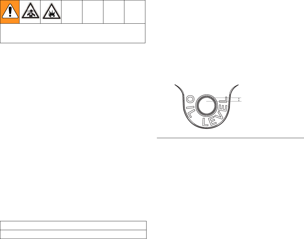
Maintenance
312759R 67
5. Lubricate all parts with a thin coat of mesamoll or
silicon oil.
6. Reassemble dispense head. See manual 312185
for details.
7. Reinstall dispense head on machine.
Flush Pneumatic Air Motor
82/0216/11
If the motor is sluggish or inefficient, flush it with a
non-flammable solvent in a well ventilated area. The rec-
ommended solvent for air motors and lubricated pumps
is Gast® Flushing Solvent (Part No. AH255 or AH255A)
or Inhibisol® Safety Solvent.
1. Disconnect the air line and muffler.
2. Add several teaspoons of solvent or spray the sol-
vent directly into the motor.
3. Rotate the shaft by hand in both directions for a few
minutes.
4. Reconnect the air line, and slowly increase the air
pressure until there is no trace of solvent in the
exhaust air.
5. Re-lubricate the motor with a squirt of light-weight
oil in the chamber.
Lubricate Pneumatic Air Motor
If an air line lubricator is not installed, the air motor must
manually be lubricated every eight hours. Lubricate the
agitator air motor by placing 10-20 drops of SAE #10
light oil in the air inlet of the motor. Run the agitator for
about 30 seconds.
Lubricate Gear Box of
Pneumatic Air Motor
01/0368-1/11
NOTE: This section does not apply to pneumatic air
motors 24J182 or 24J183.
Check Oil Level
Perform the following procedure every two days.
1. Remove oil fill plug and check oil level. The proper
oil level is indicated on the outside of the gear box
housing.
2. If the oil level is low, add 140-weight SAE gear oil or
a high quality worm gear lubricant.
3. Replace fill plug and torque to 20 ft-lb (27 N•m).
NOTE: Gear box oil is easiest to drain immediately fol-
lowing motor operation while oil is still warm.
NOTE: Do not overfill. Overfilling may cause oil to leak
out of vent cap on top of gear box.
Replace Oil
Perform the following procedure after the first 250 hours
of operation. After that, perform every six months or
every 2500 operating hours.
1. Remove gear box and drain oil.
2. Refill gear box with 140-weight SAE gear oil or a
high quality worm gear lubricant.
3. Replace fill plug and torque to 20 ft-lb (27 N•m).
NOTE: Replace gear oil more often if the environment
causes oil to become contaminated during use.
Read all manufacturer’s warning and material MSDS
to know the specific hazards of the materials used.
CAUTION
Not lubricating the air motor will cause motor failure.
FIG. 40
Approx. 1/8 in. gap
(from top of oil level
to top of fill hole)
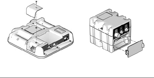
Maintenance
68 312759R
Install Upgrade Token
This procedure applies to the Advanced Display
Module (ADM) and Fluid Control Module (FCM).
1. Disconnect power to the module.
2. Remove token access panel. See FIG. 41.
3. Insert and press firmly token into slot.
NOTE: There is no preferred orientation of the token.
4. Restore power to the module. The red LED will flash
rapidly to signal that software is loading. When the
red LED stops flashing, the software is done load-
ing.
5. Disconnect power to the module.
6. Remove the token.
7. Replace token access panel.
8. Restore power to the module.
9. Repeat for each module that needs to be updated.
10. Verify new software versions on the System Data
Screen screen. See page 35.
FIG. 41: Remove Access Panel
Advanced Display Module
ti12334a
ti12904a1
Fluid Control Module,
Low Power Temperature
Control Module
Troubleshooting
312759R 69
Troubleshooting
Before starting any troubleshooting procedures, perform
the following procedure. See PR70 and PR70v Repair -
Parts manual referenced at the beginning of this manual
for detailed procedures.
1. Relieve pressure. See Pressure Relief Procedure,
page 65.
2. Disconnect AC power from the machine.
3. Allow the machine to cool if the machine has a heat
control option.
Try the recommended solutions in the order given for
each problem to avoid unnecessary repairs. Verify all
circuit breakers, switches, and controls are properly set
and wiring is correct.
Problem Cause Solution
Display Module completely dark No power Verify rear AC Power switch is ON.
Fuse blown Replace machine fuses.
Loose connection Tighten 5-pin cable on Display Mod-
ule.
Bad display module Replace Display Module.
No or incorrect amount of material
dispensed from either side.
Ball valve closed (if installed) Open tank ball valve.
Tank empty Fill tank with material.
Tank clogged Verify no obstruction in the tank.
Air in material Prime the machine until the air is
removed.
Check valve malfunction Remove; clean or replace check
valve.
Piston worn or broken Remove and replace piston if worn.
Piston stalled Input air reduced or removed Reconnect input air line to machine.
Increase air pressure regulator
adjustment.
Mixer blocked Replace static mixer.
Incorporate purge timer or decrease
purge timer delay to prevent mixer
blockage.
Open Dispense Valve (ODV) adjust-
ment too late
Readjust the ODV setting to occur
sooner.
Blocked check valve Remove check valve; clean and
replace.
Air cylinder failure Remove air cylinder and reinstall air
cylinder parts as necessary.
Significant material leaking from
pump rear seal
Pump shaft worn and/or shaft seal
worn
Remove pump shaft assembly, and
reinstall rear pump rebuild kit.

Troubleshooting
70 312759R
Material dispensed not correct weight Specific gravity of one or more of the
two materials has changed since cali-
bration
Recalibrate machine.
Machine air pressure has changed
since calibration.
Readjust air pressure regulator to
value used when machine was cali-
brated, or recalibrate machine.
Not enough material in one or more
tanks
Check tank levels; fill and prime as
necessary.
Mixer has slight obstruction Replace static mixer. Prime machine.
Check valve malfunction Remove check valve; clean or
replace as necessary.
Piston worn or broken Replace piston.
Machine dispensing off ratio One tank is empty Check tank levels. Add material if
necessary.
Tank ball valve closed Open tank ball valve. Prime machine.
Machine out of phase Re-phase machine.
Check valve malfunction Remove check valve; clean or
replace as necessary.
Piston worn or broken Replace piston.
Pumps drawing material back from
valve hose
Check valve stuck open Remove check valve, clean or
replace as necessary.
Problem Cause Solution

Troubleshooting
312759R 71
Error Codes
Code-Class-Event
Shown on Errors Screen Description
System
Behavior Ref
050X-A-Improper System Cal Improper Calibration 5
06CX-A-Invalid Key Token No or Invalid Key Token 4
A401-A-Over Current Z1 Heater Over Current, Zone #1 7
A402-A-Over Current Z2 Heater Over Current, Zone #2 7
A403-A-Over Current Z3 Heater Over Current, Zone #3 7
A404-A-Over Current Z4 Heater Over Current, Zone #4 7
A4C1-A-Fan Over Current Z1 High Relay 2 Current, Zone #1 7
A4C2-A-Fan Over Current Z2 High Relay 2 Current, Zone #2 7
A4C3-A-Fan Over Current Z3 High Relay 2 Current, Zone #3 7
A4C4-A-Fan Over Current Z4 High Relay 2 Current, Zone #4 7
A701-A-Heater Fault Z1 Unexpected Heater Current, Zone #1 7
A702-A-Heater Fault Z2 Unexpected Heater Current, Zone #2 7
A703-A-Heater Fault Z3 Unexpected Heater Current, Zone #3 7
A704-A-Heater Fault Z4 Unexpected Heater Current, Zone #4 7
A7C1-A-Fan Output Fault Z1 Unexpected Relay 2 Current, Zone #1 7
A7C2-A-Fan Output Fault Z2 Unexpected Relay 2 Current, Zone #2 7
A7C3-A-Fan Output Fault Z3 Unexpected Relay 2 Current, Zone #3 7
A7C4-A-Fan Output Fault Z4 Unexpected Relay 2 Current, Zone #4 7
B10X-A-Small Shot Request Less Than Minimum Shot Requested 5
CAC1-A-Comm. Error FCM 1 Communication Error, FCM3 #1 2
CAC1-A-Comm. Error FCM2 Communication Error, FCM3 #2 3
CAC1-A-Comm. Error Heat Z1 Communication Error, Heat Zone #1 1
CAC1-A-Comm. Error Heat Z2 Communication Error, Heat Zone #2 1
CAC1-A-Comm. Error Heat Z3 Communication Error, Heat Zone #3 1
CAC1-A-Comm. Error Heat Z4 Communication Error, Heat Zone #4 1
DEFX-A-Piston Timeout Piston Stroke Timeout 5
DJ0X-D-Linear Sensor Fault Bad Linear Position Sensor 6
F2A-Low Flow A Side Low A Side Fluid Flow, relative to calibra-
tion and user-input allowable variance.
See Dispense Check Options, Screen
#4 on page 31.
6

Troubleshooting
72 312759R
F2B-Low Flow B Side Low B Side Fluid Flow, relative to calibra-
tion and user-input allowable variance.
See Dispense Check Options, Screen
#4 on page 31.
6
F2FX-D-Delta Velocity Minus Delta Velocity Minus 6
F3FX-D-Delta Velocity Plus Delta Velocity Plus 6
F6A-Flow Meter A Problem Flow Meter A Problem, or bad connection
between Fluid Control Module and Flow
Meter A
6
F6B-Flow Meter B Problem Flow Meter B Problem, or bad connection
between Fluid Control Module and Flow
Meter B
6
L2AX-D-Low Level Tank A Low Material Level, Tank A 6
L2BX-D-Low Level Tank B Low Material Level, Tank B 6
L2FX-D-Low Level Tank A/B Low Material Level, Both Tanks 6
L8AX-D-Refill Timeout A Auto Refill Failed, A Side 6
L8AX-D-Refill Timeout B Auto Refill Failed, B Side 6
P2AX-D-Low Pressure A A Side Low Pressure, relative to calibra-
tion and user-input allowable variance.
See Dispense Check Options, Screen
#4 on page 31.
6
P2BX-D-Low Pressure B B Side Low Pressure, relative to calibra-
tion and user-input allowable variance.
See Dispense Check Options, Screen
#4 on page 31.
6
P3AX-D-High Pressure A A Side High Pressure, relative to calibra-
tion and user-input allowable variance.
See Dispense Check Options, Screen
#4 on page 31.
6
P3BX-D-High Pressure B B Side High Pressure, relative to calibra-
tion and user-input allowable variance.
See Dispense Check Options, Screen
#4 on page 31.
6
P6AX-D-Pressure Fault A Problem with A Side Piston Pressure
Transducer or Transducer Connection
6
P6BX-D-Pressure Fault B Problem with B Side Piston Pressure
Transducer or Transducer Connection
6
P6DX-D-Pressure Fault A/B Problem with A and B Side Piston Pres-
sure Transducer or Transducer Connec-
tion
6
Code-Class-Event
Shown on Errors Screen Description
System
Behavior Ref

Troubleshooting
312759R 73
P7DX-D-Out of Phase Machine Out of Phase, relative to calibra-
tion and user-input allowable variance.
See Dispense Check Options, Screen
#4 on page 31.
6
R2-A:B Ratio Low A:B Ratio is low, relative to calibration and
user-input allowable variance. See Dis-
pense Check Options, Screen #4 on
page 31.
6
R3-A:B Ratio High A:B Ratio is high, relative to calibration
and user-input allowable variance. See
Dispense Check Options, Screen #4 on
page 31.
6
T201-D-Low Material Temp Z1 Material Below Temperature, Zone #1 8
T202-D-Low Material Temp Z2 Material Below Temperature, Zone #2 8
T203-D-Low Material Temp Z3 Material Below Temperature, Zone #3 8
T204-D-Low Material Temp Z4 Material Below Temperature, Zone #4 8
T401-A-High Material Temp Z1 Material Over Temperature, Zone #1 7
T402-A-High Material Temp Z2 Material Over Temperature, Zone #2 7
T403-A-High Material Temp Z3 Material Over Temperature, Zone #3 7
T404-A-High Material Temp Z4 Material Over Temperature, Zone #4 7
T4C1-A-Blanket Over Temp Z1 Blanket Over Temperature, Zone #1 7
T4C2-A-Blanket Over Temp Z2 Blanket Over Temperature, Zone #2 7
T4C3-A-Blanket Over Temp Z3 Blanket Over Temperature, Zone #3 7
T4C4-A-Blanket Over Temp Z4 Blanket Over Temperature, Zone #4 7
T601-A-Material RTD Fault Z1 Material RTD Fault, Zone #1 7
T602-A-Material RTD Fault Z2 Material RTD Fault, Zone #2 7
T603-A-Material RTD Fault Z3 Material RTD Fault, Zone #3 7
T604-A-Material RTD Fault Z4 Material RTD Fault, Zone #4 7
T6C1-A-Blanket RTD Fault Z1 Blanket RTD Fault, Zone #1 7
T6C2-A-Blanket RTD Fault Z2 Blanket RTD Fault, Zone #2 7
T6C3-A-Blanket RTD Fault Z3 Blanket RTD Fault, Zone #3 7
T6C4-A-Blanket RTD Fault Z4 Blanket RTD Fault, Zone #4 7
T801-D-No Heat Z1 No Temperature Rise, Zone #1 8
T802-D-No Heat Z2 No Temperature Rise, Zone #2 8
T803-D-No Heat Z3 No Temperature Rise, Zone #3 8
Code-Class-Event
Shown on Errors Screen Description
System
Behavior Ref
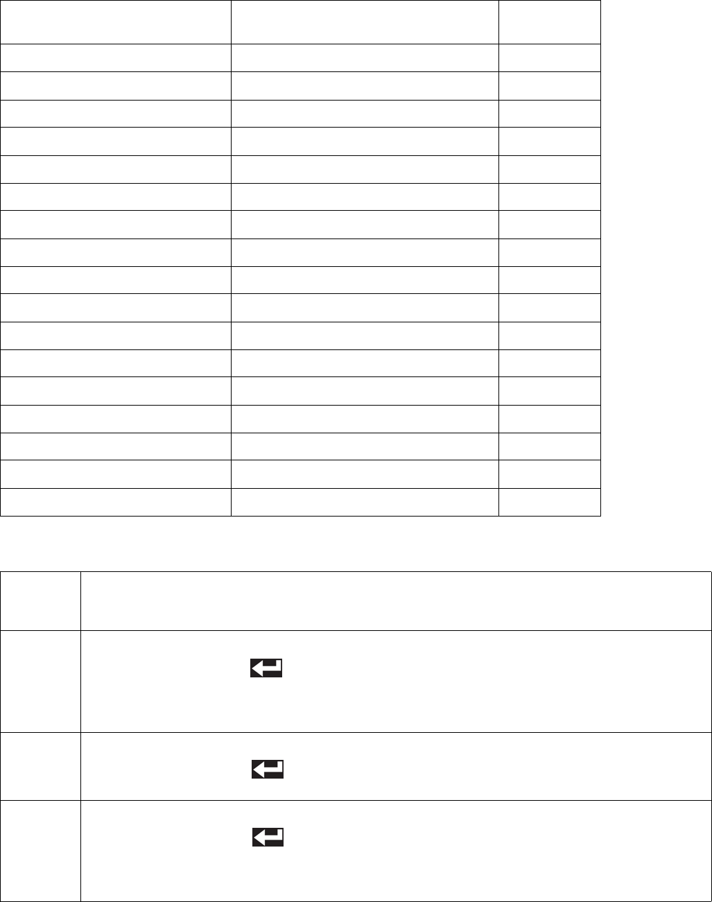
Troubleshooting
74 312759R
System Behavior Descriptions
T804-D-No Heat Z4 No Temperature Rise, Zone #4 8
T901-A-Temp Switch Cutoff Z1 Over Temp Switch Open, Zone #1 7
T902-A-Temp Switch Cutoff Z2 Over Temp Switch Open, Zone #2 7
T903-A-Temp Switch Cutoff Z3 Over Temp Switch Open, Zone #3 7
T904-A-Temp Switch Cutoff Z4 Over Temp Switch Open, Zone #4 7
T9C1-A-Control Shutdown Z1 PCB Over Temperature, Zone #1 7
T9C2-A-Control Shutdown Z2 PCB Over Temperature, Zone #2 7
T9C3-A-Control Shutdown Z3 PCB Over Temperature, Zone #3 7
T9C4-A-Control Shutdown Z4 PCB Over Temperature, Zone #4 7
WM01-A-Current Fault Z1 High Relay 1 Current, Zone #1 7
WM02-A-Current Fault Z2 High Relay 1 Current, Zone #2 7
WM03-A-Current Fault Z3 High Relay 1 Current, Zone #3 7
WM04-A-Current Fault Z4 High Relay 1 Current, Zone #4 7
WMC1-A-Control Fault Z1 Unexpected Relay 1 Current, Zone #1 7
WMC2-A-Control Fault Z2 Unexpected Relay 1 Current, Zone #2 7
WMC3-A-Control Fault Z3 Unexpected Relay 1 Current, Zone #3 7
WMC4-A-Control Fault Z4 Unexpected Relay 1 Current, Zone #4 7
Code-Class-Event
Shown on Errors Screen Description
System
Behavior Ref
System
Behavior
Reference System Behavior Description
1
When this error is generated, a pop-up with the error-code will be shown until it is acknowledged by
pressing the Enter button ( ). The heat control will be turned off, any auto-sequencing in progress
will be stopped, and the foot switch will be disabled until the error-code is acknowledged. When the
error condition is cleared, the heat control may be turned back on from the Home screen. This error
will not disable purge or recirculation operation.
2
When this error is generated, a pop-up with the error-code will be shown until it is acknowledged by
pressing the Enter button ( ). All physical machine operation will be disabled until the error condi-
tion is corrected. The display module can still be used but all machine commands sent will be ignored.
3
When this error is generated, a pop-up with the error-code will be shown until it is acknowledged by
pressing the Enter button ( ). Any auto-sequencing in progress will be stopped and the foot
switch will be disabled until the error-code is acknowledged. This error will not disable purge or recir-
culation operation. All features dependent on Fluid Control Module #2 will be disabled until the error
condition is corrected.

Troubleshooting
312759R 75
4
When this error is generated, a pop-up with the error-code will be shown continuously until the error
condition is corrected. The machine and display module are completely disabled until the error condi-
tion is corrected.
5
When this error is generated, a pop-up with the error-code will be shown. Any auto-sequencing, purge
timer or recirculation timer operation in progress will be stopped and the foot switch will be disabled
until the error-condition is cleared. The error-code pop-up will be shown until the error condition is
cleared. When the error condition is cleared, all options may be turned back on.
6
When this error is generated, a pop-up with the error-code will be shown until it is acknowledged by
pressing the Enter button ( ). Any auto-sequencing in progress will be stopped, and the foot
switch will be disabled until the error-code is acknowledged. Once the error-code pop-up is acknowl-
edged, the machine will return to normal operation The error will be shown in the Errors screen until
the condition is cleared. The error-code pop-up will not reappear unless the error condition is cleared
and then reappears. This error will not disable purge or recirculation operation.
7
When this error is generated, a pop-up with the error-code will be shown until it is acknowledged by
pressing the Enter button ( ). All heat options will be turned off, any auto-sequencing in progress
will be stopped, and the foot switch will be disabled until the error-code is acknowledged. When the
error condition is cleared, the heat control may be turned back on from the Home screen. This error
will not disable purge or recirculation operation.
8
When this error is generated, a pop-up with the error-code will be shown until it is acknowledged by
pressing the Enter button ( ). All heat options will remain on, any auto-sequencing in progress will
be stopped, and the foot switch will be disabled until the error-code is acknowledged. This error will
not disable purge or recirculation operation.
System
Behavior
Reference System Behavior Description

Kits
76 312759R
Kits
Mixer and Shroud Options
MD2 Valve Kits
Machine Rebuild Kits
Tank Accessories
†Item includes only the pump. A vacuum kit must be pur-
chased to install the pump onto the tank.
Kit includes all parts needed to connect a nitrogen tank
to the material tank.
Part Description
LC0063 Mixer, 3/16 in. (6.5 mm) x 32, 10 Mixers
with shroud
LC0057 Mixer, 1/4 in. (6.5 mm) x 24, 10 Mixers
with shroud
LC0058 Mixer, 3/8 in. (9.8 mm) x 24, 10 Mixers
with shroud
LC0059 Mixer, 3/8 in. (9.8 mm) x 36, 10 Mixers
with shroud
LC0060 Mixer, 3/8 in. (9.8 mm) Combo, 10 Mixers
with shroud
LC0061 Mixer, 3/16 in. (4.8 mm) x 32 Luer Lock, 10
Mixers with shroud
LC0062 Mixer, 1/4 in. (6.5 mm) x 24 Luer Lock, 10
Mixers with shroud
LC0077 Mixer, 3/16 in. (4.8 mm) x 32, 50 Mixers
LC0078 Mixer, 1/4 in. (6.5 mm) x 24, 50 Mixers
LC0079 Mixer, 3/8 in. (9.8 mm) x 24, 50 Mixers
LC0080 Mixer, 3/8 in. (9.8 mm) x 36, 50 Mixers
LC0081 Mixer, 3/8 in. (9.8 mm) combo, 50 Mixers
LC0083 Mixer, 1/4 in. (6.5 mm) x 24 Luer Lock, 50
Mixers
LC0082 Mixer, 3/16 in. (4.8 mm) x 32 Luer Lock, 50
Mixers
LC0084 Mixer, 3/16 in. (4.8 mm) x 32, 250 Mixers
LC0085 Mixer, 1/4 in. (6.5 mm) x 24, 250 Mixers
LC0086 Mixer, 3/8 in. (9.8 mm) x 24, 250 Mixers
LC0087 Mixer, 3/8 in. (9.8 mm) x 36, 250 Mixers
LC0088 Mixer, 3/8 in. (9.8 mm) combo, 250 Mixers
LC0089 Mixer, 3/16 in. (4.8 mm) x 32 Luer Lock,
250 Mixers
LC0090 Mixer, 1/4 in. (6.5 mm) x 24 Luer Lock, 250
Mixers
See MD2 Dispense Valve instruction manual refer-
enced at the beginning of this manual for installa-
tion instructions or for more information.
Part Description
255217 MD2, kit rebuild, air cylinder
255218 MD2, kit rebuild, back-end of wet section
(no needle or seat)
255219 MD2, Soft Seat rebuild, needle and nose
255220 MD2, convert Soft Seat nose to Hard Seat
(Hard Seat rebuild), needle and nose
See the PR70 and PR70v Repair - Parts manual
referenced at the beginning of this manual for parts
included in each kit.
Part Description
LC0091 3.0 in. Air Cylinder rebuild kit
LC0092 4.5 in. Air Cylinder rebuild kit
LC0093 Check Valve rebuild kit, Stainless Steel Ball
LC0318 Check Valve rebuild kit, Carbide Ball
LC0094 Rear Pump Seal rebuild kit
Part Description
LC0097 Desiccant Dryer, 3/8 in. NPT with adapter
and cartridge
LC0098 Desiccant Dryer refill cartridge
LC0095 Nitrogen Harness Kit for 30 L and 60 L
tank, 1 tank
LC0096 Nitrogen Harness Kit for 30 L and 60 L
tank, 2 tanks
†LC0099 Vacuum Transfer Pump, 120V, down to 25
To r r
†LC0100 Vacuum Transfer Pump, 240V, down to 25
To r r
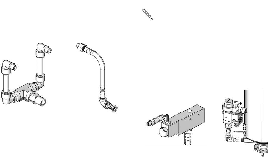
Kits
312759R 77
Vacuum Kits
These vacuum kits contain the parts necessary to
attach a vacuum pump to the tanks.
Refill Kits
Refill Kits 256659 and 256660 are designed to turn on
and off a transfer pump as needed to keep the tanks at
the proper fluid level. Tank Refill Kit 256577 is designed
to open and close a valve to allow fluid to flow into the
tank from an always-on transfer pump. Tank Refill
Kit 256577 includes the parts necessary to install on the
base or lid of a 7.5 L, 30 L, or 60 L tank.
External Control Interface Connection Kit
Part Description
256205 Vacuum Kit, Single On-Board Tank
256206 Vacuum Kit, Two On-Board Tanks
256207 Vacuum Kit, Single Off-Board Tank
256209 Vacuum Kit, Two Off-Board Tanks
Assembly 256206
Shown
Assembly 256207
Shown
On-Board
Vacuum Kits
Off-Board
Vacuum Kits
ti12588a ti12589a
See Tank Refill Kit 256577 Installation on page
19 for installation information.
Part Description
256659 Refill Kit, 1/4 npt, solenoid, 24V
256660 Refill Kit, 1/2 npt, solenoid, 24V
256577 Tank Refill Kit
Part Description
LC0008 Cord, I/O interface and splitter
Assembly 256659
Shown
Assembly 256577 shown
installed on tank for reference
ti12590a
ti12591b
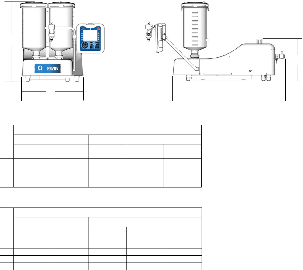
Dimensions
Machine with On-Board Tanks
PR70
PR70v
† Assembly dimensions listed are maximum for all assemblies under the given title.
On-board stainless steel tank dimensions include ball valves and vacuum de-gas in maximum height calculation.
Ref
† Assembly Dimensions, in. (mm)
Polyethylene Tanks Stainless Steel Tanks
No Agitators With Agitators 3 L 7.5 L, No
Agitators
7.5 L, with
Agitators
A 26.4 (670) 38.6 (980) 28.2 (716) 38.2 (970) 39.9 (1013)
B 18.5 (470) 18.5 (470) 15.5 (394) 15.5 (394) 15.5 (394)
C 30.6 (778) 30.6 (778) 30.6 (778) 30.6 (778) 30.6 (778)
D 13.4 (340) 13.4 (340) 13.4 (340) 13.4 (340) 13.4 (340)
Ref
† Assembly Dimensions, in. (mm)
Polyethylene Tanks Stainless Steel Tanks
No Agitators With Agitators 3L, No
Agitators
7.5 L, No
Agitators
7.5 L, with
Agitators
A 30.0 (762) 39.4 (1001) 29.0 (737) 39.0 (991) 40.6 (1031)
B 20.9 (531) 20.9 (531) 20.9 (531) 20.9 (531) 20.9 (531)
C 38.6 (980) 38.6 (980) 38.6 (980) 38.6 (980) 38.6 (980)
D 14.3 (363) 14.3 (363) 14.3 (363) 14.3 (363) 14.3 (363)
B
A
C
D
ti12621b ti12622b
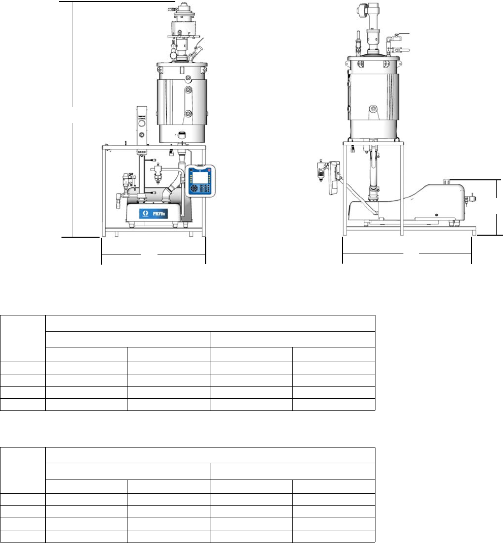
Dimensions
312759R 79
Machine with Off-Board Tanks
PR70
PR70v
† Assembly dimensions listed are maximum for all assemblies under the given title.
C
B
A
D
ti12623c ti12624c
Ref
† Assembly Dimensions, in. (mm)
30 L Tank 60 L Tank
No Agitators With Agitators No Agitators With Agitators
A 75.7 (1923) 83.4 (2118) 64.9 (1648) 89.5 (2273)
B 32.1 (815) 32.1 (815) 32.1 (815) 32.1 (815)
C 29.3 (744) 29.3 (744) 29.3 (744) 29.3 (744)
D 16.0 (406) 16.0 (406) 16.0 (406) 16.0 (406)
Ref
† Assembly Dimensions, in. (mm)
30 L Tank 60 L Tank
No Agitators With Agitators No Agitators With Agitators
A 75.7 (1923) 83.4 (2118) 64.9 (1648) 89.5 (2273)
B 32.1 (815) 32.1 (815) 32.1 (815) 32.1 (815)
C 40.1 (1019) 40.1 (1019) 40.1 (1019) 40.1 (1019)
D 17.0 (432) 17.0 (432) 17.0 (432) 17.0 (432)
Technical Data
Gast® is registered trademark of Gast Manufacturing.
Inhibisol® is a registered trademark of Penetone Corp.
Metering Pump Effective Area . . . . . . . . . . . . . . . . . . . . . 80 to 960 mm2 (0.124 to 1.49 in.2) per side
Small Air Cylinder Effective Area . . . . . . . . . . . . . . . . . . 4560 mm2 (7.07 in.2)
Large Air Cylinder Effective Area . . . . . . . . . . . . . . . . . . 10260 mm2 (15.9 in.2)
Maximum Stroke Length . . . . . . . . . . . . . . . . . . . . . . . . . 38.1 mm (1.50 in.)
Minimum Stroke Length . . . . . . . . . . . . . . . . . . . . . . . . . 5.8 mm (0.23 in.)
Volume per Cycle . . . . . . . . . . . . . . . . . . . . . . . . . . . . . . 2 to 70 cc (0.12 to 4.3 in.3)
Pump Cycles per 1 L (0.26 gal) . . . . . . . . . . . . . . . . . . . . 14.3 to 500 cycles (varies by piston size)
Ratios (fixed) . . . . . . . . . . . . . . . . . . . . . . . . . . . . . . . . . . 1:1 to 12:1 (depending upon cylinders selected)
Maximum Fluid Working Pressure . . . . . . . . . . . . . . . . . 3000 psi (20.7 MPa, 207 bar)
Maximum Air Input Pressure . . . . . . . . . . . . . . . . . . . . . . 100 psi (0.7 MPa, 7 bar)
Maximum Cycle Rate . . . . . . . . . . . . . . . . . . . . . . . . . . . 30 cpm
Maximum Operating Temperature . . . . . . . . . . . . . . . . . . 70°C (160°F), nylon pistons 50°C (120°F) UHMWPE pis-
tons or PE Tanks
Air Inlet Size . . . . . . . . . . . . . . . . . . . . . . . . . . . . . . . . . . 1/4 NPT female
Pump Fluid Outlet Size . . . . . . . . . . . . . . . . . . . . . . . . . . -03, -04, -06, -08 or –12 JIC fittings for 3/16 in. (4.8 mm),
1/4 in. (6.4 mm), 3/8 in. (9.5 mm), 1/2 in. (12.7 mm),
3/4 in. (19.1 mm) hoses
Wetted Parts . . . . . . . . . . . . . . . . . . . . . . . . . . . . . . . . . . 303/304, 17-4 PH, hard chrome, Chromex™, carbide,
Chemical Resistant O-rings, PTFE, nylon, UHMWPE
Weight . . . . . . . . . . . . . . . . . . . . . . . . . . . . . . . . . . . . . . . 55 kg (120 lb) typical with two 7.5 L tanks
150 kg (330 lb) typical with two 60 L tanks
Sound Pressure Level (at typical operator station for
machine mounted Dispense Valve . . . . . . . . . . . . . . . . . 82 dBA
Compressed Air . . . . . . . . . . . . . . . . . . . . . . . . . . . . . . . Less than 10 scfm typical (varies with cycle times)
Electrical Power . . . . . . . . . . . . . . . . . . . . . . . . . . . . . . . . • 100-240 V 50/60Hz, 1 phase for machine – 80 Watts
• 208-240V 50/60Hz, 1 phase for heat – 11 kW max
• 120 or 240 VAC 50/60Hz 1 phase for on-board agita-
tors, 80 Watts
• 240 VAC 50/60Hz 1 phase for off-board agitators,
600 Watts

Technical Data
312759R 81

Graco Standard Warranty
Graco warrants all equipment referenced in this document which is manufactured by Graco and bearing its name to be free from defects in
material and workmanship on the date of sale to the original purchaser for use. With the exception of any special, extended, or limited warranty
published by Graco, Graco will, for a period of twelve months from the date of sale, repair or replace any part of the equipment determined by
Graco to be defective. This warranty applies only when the equipment is installed, operated and maintained in accordance with Graco’s written
recommendations.
This warranty does not cover, and Graco shall not be liable for general wear and tear, or any malfunction, damage or wear caused by faulty
installation, misapplication, abrasion, corrosion, inadequate or improper maintenance, negligence, accident, tampering, or substitution of
non-Graco component parts. Nor shall Graco be liable for malfunction, damage or wear caused by the incompatibility of Graco equipment with
structures, accessories, equipment or materials not supplied by Graco, or the improper design, manufacture, installation, operation or
maintenance of structures, accessories, equipment or materials not supplied by Graco.
This warranty is conditioned upon the prepaid return of the equipment claimed to be defective to an authorized Graco distributor for verification of
the claimed defect. If the claimed defect is verified, Graco will repair or replace free of charge any defective parts. The equipment will be returned
to the original purchaser transportation prepaid. If inspection of the equipment does not disclose any defect in material or workmanship, repairs will
be made at a reasonable charge, which charges may include the costs of parts, labor, and transportation.
THIS WARRANTY IS EXCLUSIVE, AND IS IN LIEU OF ANY OTHER WARRANTIES, EXPRESS OR IMPLIED, INCLUDING BUT NOT LIMITED
TO WARRANTY OF MERCHANTABILITY OR WARRANTY OF FITNESS FOR A PARTICULAR PURPOSE.
Graco’s sole obligation and buyer’s sole remedy for any breach of warranty shall be as set forth above. The buyer agrees that no other remedy
(including, but not limited to, incidental or consequential damages for lost profits, lost sales, injury to person or property, or any other incidental or
consequential loss) shall be available. Any action for breach of warranty must be brought within two (2) years of the date of sale.
GRACO MAKES NO WARRANTY, AND DISCLAIMS ALL IMPLIED WARRANTIES OF MERCHANTABILITY AND FITNESS FOR A
PARTICULAR PURPOSE, IN CONNECTION WITH ACCESSORIES, EQUIPMENT, MATERIALS OR COMPONENTS SOLD BUT NOT
MANUFACTURED BY GRACO. These items sold, but not manufactured by Graco (such as electric motors, switches, hose, etc.), are subject to
the warranty, if any, of their manufacturer. Graco will provide purchaser with reasonable assistance in making any claim for breach of these
warranties.
In no event will Graco be liable for indirect, incidental, special or consequential damages resulting from Graco supplying equipment hereunder, or
the furnishing, performance, or use of any products or other goods sold hereto, whether due to a breach of contract, breach of warranty, the
negligence of Graco, or otherwise.
FOR GRACO CANADA CUSTOMERS
The Parties acknowledge that they have required that the present document, as well as all documents, notices and legal proceedings entered into,
given or instituted pursuant hereto or relating directly or indirectly hereto, be drawn up in English. Les parties reconnaissent avoir convenu que la
rédaction du présente document sera en Anglais, ainsi que tous documents, avis et procédures judiciaires exécutés, donnés ou intentés, à la suite
de ou en rapport, directement ou indirectement, avec les procédures concernées.
Graco Information
For the latest information about Graco products, visit www.graco.com.
TO PLACE AN ORDER, contact your Graco distributor or call to identify the nearest distributor.
Toll Free: 1-800-746-1334 or Fax: 330-966-3006
All written and visual data contained in this document reflects the latest product information available at the time of publication.
Graco reserves the right to make changes at any time without notice.
For patent information, see www.graco.com/patents.
Original instructions. This manual contains English. MM 312759
Graco Headquarters: Minneapolis
International Offices: Belgium, China, Japan, Korea
GRACO INC. AND SUBSIDIARIES • P.O. BOX 1441 • MINNEAPOLIS MN 55440-1441 • USA
Copyright 2008, Graco Inc. All Graco manufacturing locations are registered to ISO 9001.
www.graco.com
Revised February 2014
