Graco 312795E Merkur Bellows Pump Assembly Users Manual 312795E, Assembly, Instructions/Parts, English
312795E to the manual 7f950da0-1fe1-47c5-ada3-6ba4faee4fda
2015-04-02
: Graco Graco-312795E-Merkur-Bellows-Pump-Assembly-Users-Manual-685840 graco-312795e-merkur-bellows-pump-assembly-users-manual-685840 graco pdf
Open the PDF directly: View PDF ![]() .
.
Page Count: 32
312795E
EN
Instructions-Parts
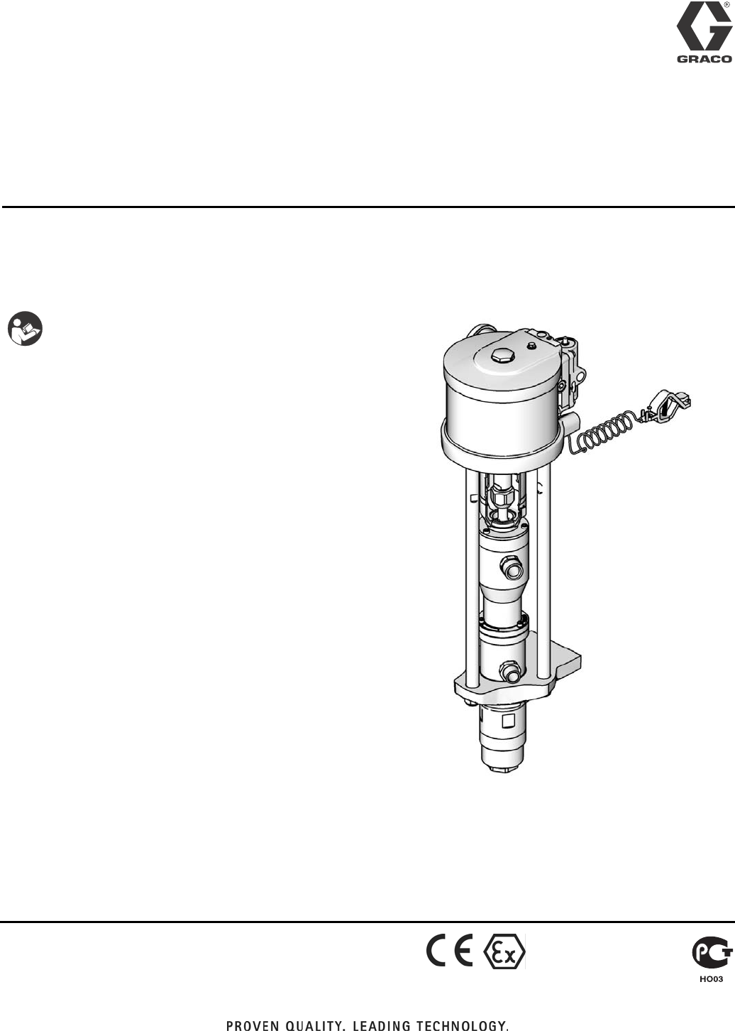
Merkur™ Bellows
Pump Assembly
For pumping isocyanates, UV coatings, and other moisture-sensitive materials. For
professional use only.
See page 7 for model information, including maximum
working pressure.
Important Safety Instructions
Read all warnings and instructions in this
manual. Save these instructions.
ti15361a
II 2 G c IIB T3 (200°C)

Related Manuals
2312795E
Contents
Related Manuals . . . . . . . . . . . . . . . . . . . . . . . . . . . 2
Warnings . . . . . . . . . . . . . . . . . . . . . . . . . . . . . . . . . 3
Important Two-Component Material Information . 5
Isocyanate Conditions . . . . . . . . . . . . . . . . . . . . . 5
Material Self-ignition . . . . . . . . . . . . . . . . . . . . . . 5
Keep Components A and B Separate . . . . . . . . . 5
Moisture Sensitivity of Isocyanates . . . . . . . . . . . 5
Changing Materials . . . . . . . . . . . . . . . . . . . . . . . 5
Models . . . . . . . . . . . . . . . . . . . . . . . . . . . . . . . . . . . 6
Pump Data . . . . . . . . . . . . . . . . . . . . . . . . . . . . . . . . 7
Component Identification . . . . . . . . . . . . . . . . . . . . 8
Installation . . . . . . . . . . . . . . . . . . . . . . . . . . . . . . . 10
General Information . . . . . . . . . . . . . . . . . . . . . 10
Prepare the Operator . . . . . . . . . . . . . . . . . . . . 10
Prepare the Site . . . . . . . . . . . . . . . . . . . . . . . . 11
Grounding . . . . . . . . . . . . . . . . . . . . . . . . . . . . . 12
Mount the Pump . . . . . . . . . . . . . . . . . . . . . . . . 12
Air and Fluid Hoses . . . . . . . . . . . . . . . . . . . . . . 12
Accessories . . . . . . . . . . . . . . . . . . . . . . . . . . . . 13
Operation . . . . . . . . . . . . . . . . . . . . . . . . . . . . . . . . 14
Pressure Relief Procedure . . . . . . . . . . . . . . . . 14
Flush the Pump Before First Use . . . . . . . . . . . 14
Trigger Lock . . . . . . . . . . . . . . . . . . . . . . . . . . . . 14
Prime and Adjust the Pump . . . . . . . . . . . . . . . 15
Shutdown and Care of the Pump . . . . . . . . . . . 15
Maintenance . . . . . . . . . . . . . . . . . . . . . . . . . . . . . . 16
Preventive Maintenance Schedule . . . . . . . . . . 16
Tighten Threaded Connections . . . . . . . . . . . . . 16
Flushing . . . . . . . . . . . . . . . . . . . . . . . . . . . . . . . 16
Troubleshooting . . . . . . . . . . . . . . . . . . . . . . . . . . . 17
Repair . . . . . . . . . . . . . . . . . . . . . . . . . . . . . . . . . . . 18
General Information . . . . . . . . . . . . . . . . . . . . . . 18
Preparation . . . . . . . . . . . . . . . . . . . . . . . . . . . . 18
Disconnect the Pump . . . . . . . . . . . . . . . . . . . . 18
Reconnect the Pump . . . . . . . . . . . . . . . . . . . . . 20
Parts . . . . . . . . . . . . . . . . . . . . . . . . . . . . . . . . . . . . 22
Parts That Vary by Model . . . . . . . . . . . . . . . . . 23
Repair Kits . . . . . . . . . . . . . . . . . . . . . . . . . . . . . . . 24
Wall Mounting Kits . . . . . . . . . . . . . . . . . . . . . . . 24
Cart Mounting Kit 24E879 . . . . . . . . . . . . . . . . . 24
Accessories . . . . . . . . . . . . . . . . . . . . . . . . . . . . 24
Performance Charts . . . . . . . . . . . . . . . . . . . . . . . . 26
Pump Dimensions . . . . . . . . . . . . . . . . . . . . . . . . . 30
Wall Bracket Mounting Dimensions . . . . . . . . . . . 31
Technical Data . . . . . . . . . . . . . . . . . . . . . . . . . . . . 31
Graco Standard Warranty . . . . . . . . . . . . . . . . . . . 32
Related Manuals
Manual Description
312793 Merkur Bellows Displacement Pump
312796 NXT™ Air Motor
312799 Merkur Bellows Spray Packages, AA
and Airless
312798 Merkur Electrostatic Spray Packages
Warnings
312795E 3
Warnings
The following warnings are for the setup, use, grounding, maintenance, and repair of this equipment. The exclama-
tion point symbol alerts you to a general warning and the hazard symbols refer to procedure-specific risks. When
these symbols appear in the body of this manual, refer back to these Warnings. Product-specific hazard symbols and
warnings not covered in this section may appear throughout the body of this manual where applicable.
WARNINGWARNINGWARNING
WARNING
FIRE AND EXPLOSION HAZARD
Flammable fumes, such as solvent and paint fumes, in work area can ignite or explode. To help prevent
fire and explosion:
• Use equipment only in well ventilated area.
• Eliminate all ignition sources; such as pilot lights, cigarettes, portable electric lamps, and plastic drop
cloths (potential static arc).
• Keep work area free of debris, including solvent, rags and gasoline.
• Do not plug or unplug power cords, or turn power or light switches on or off when flammable fumes
are present.
• Ground all equipment in the work area. See Grounding instructions.
• Use only grounded hoses.
• Hold gun firmly to side of grounded pail when triggering into pail.
• If there is static sparking or you feel a shock, stop operation immediately. Do not use equipment
until you identify and correct the problem.
• Keep a working fire extinguisher in the work area.
Static charge may build up on plastic parts during cleaning and could discharge and ignite flammable
vapors. To help prevent fire and explosion:
• Clean plastic parts only in a well ventilated area.
• Do not clean with a dry cloth.
• Do not operate electrostatic guns in equipment work area.
SKIN INJECTION HAZARD
High-pressure fluid from gun, hose leaks, or ruptured components will pierce skin. This may look like just
a cut, but it is a serious injury that can result in amputation. Get immediate surgical treatment.
• Do not spray without tip guard and trigger guard installed.
• Engage trigger lock when not spraying.
• Do not point gun at anyone or at any part of the body.
• Do not put your hand over the spray tip.
• Do not stop or deflect leaks with your hand, body, glove, or rag.
• Follow the Pressure Relief Procedure when you stop spraying and before cleaning, checking, or ser-
vicing equipment.
• Tighten all fluid connections before operating the equipment.
• Check hoses and couplings daily. Replace worn or damaged parts immediately.
Warnings
4312795E
EQUIPMENT MISUSE HAZARD
Misuse can cause death or serious injury.
• Do not operate the unit when fatigued or under the influence of drugs or alcohol.
• Do not exceed the maximum working pressure or temperature rating of the lowest rated system com-
ponent. See Technical Data in all equipment manuals.
• Use fluids and solvents that are compatible with equipment wetted parts. See Technical Data in all
equipment manuals. Read fluid and solvent manufacturer’s warnings. For complete information about
your material, request MSDS from distributor or retailer.
• Do not leave the work area while equipment is energized or under pressure. Turn off all equipment
and follow the Pressure Relief Procedure when equipment is not in use.
• Check equipment daily. Repair or replace worn or damaged parts immediately with genuine manufac-
turer’s replacement parts only.
• Do not alter or modify equipment.
• Use equipment only for its intended purpose. Call your distributor for information.
• Route hoses and cables away from traffic areas, sharp edges, moving parts, and hot surfaces.
• Do not kink or over bend hoses or use hoses to pull equipment.
• Keep children and animals away from work area.
• Comply with all applicable safety regulations.
MOVING PARTS HAZARD
Moving parts can pinch, cut or amputate fingers and other body parts.
• Keep clear of moving parts.
• Do not operate equipment with protective guards or covers removed.
• Pressurized equipment can start without warning. Before checking, moving, or servicing equipment,
follow the Pressure Relief Procedure and disconnect all power sources.
SUCTION HAZARD
Powerful suction could cause serious injury.
• Never place hands near the pump fluid inlet when pump is operating or pressurized.
TOXIC FLUID OR FUMES HAZARD
Toxic fluids or fumes can cause serious injury or death if splashed in the eyes or on skin, inhaled, or swal-
lowed.
• Read MSDSs to know the specific hazards of the fluids you are using.
• Store hazardous fluid in approved containers, and dispose of it according to applicable guidelines.
• Always wear chemically impermeable gloves when spraying, dispensing, or cleaning equipment.
PERSONAL PROTECTIVE EQUIPMENT
You must wear appropriate protective equipment when operating, servicing, or when in the operating area
of the equipment to help protect you from serious injury, including eye injury, hearing loss, inhalation of
toxic fumes, and burns. This equipment includes but is not limited to:
• Protective eyewear, and hearing protection.
• Respirators, protective clothing, and gloves as recommended by the fluid and solvent manufacturer.
WARNINGWARNINGWARNING
WARNING
Important Two-Component Material Information
312795E 5
Important Two-Component Material Information
Isocyanate Conditions
Material Self-ignition
Keep Components A and B
Separate
Moisture Sensitivity of
Isocyanates
Isocyanates (ISO) are catalysts used in two component
coatings. ISO will react with moisture (such as humidity)
to form small, hard, abrasive crystals, which become
suspended in the fluid. Eventually a film will form on the
surface and the ISO will begin to gel, increasing in vis-
cosity. If used, this partially cured ISO will reduce perfor-
mance and the life of all wetted parts.
NOTE: The amount of film formation and rate of crystal-
lization varies depending on the blend of ISO, the
humidity, and the temperature.
To prevent exposing ISO to moisture:
• Always use a sealed container with a desiccant
dryer in the vent, or a nitrogen atmosphere. Never
store ISO in an open container.
• Use moisture-proof hoses specifically designed for
ISO, such as those supplied with your system.
• Never use reclaimed solvents, which may contain
moisture. Always keep solvent containers closed
when not in use.
• Never use solvent on one side if it has been contam-
inated from the other side.
• Always lubricate threaded parts with ISO pump oil
or grease when reassembling.
Changing Materials
• When changing materials, flush the equipment mul-
tiple times to ensure it is thoroughly clean.
• Always clean the fluid inlet strainers after flushing.
• Check with your material manufacturer for chemical
compatibility.
• Most materials use ISO on the A side, but some use
ISO on the B side.
Spraying or dispensing materials containing isocya-
nates creates potentially harmful mists, vapors, and
atomized particulates.
Read material manufacturer’s warnings and material
MSDS to know specific hazards and precautions
related to isocyanates.
Prevent inhalation of isocyanate mists, vapors, and
atomized particulates by providing sufficient ventila-
tion in the work area. If sufficient ventilation is not
available, a supplied-air respirator is required for
everyone in the work area.
To prevent contact with isocyanates, appropriate per-
sonal protective equipment, including chemically
impermeable gloves, boots, aprons, and goggles, is
also required for everyone in the work area.
Some materials may become self-igniting if applied
too thickly. Read material manufacturer’s warnings
and material MSDS.
Cross-contamination can result in cured material in
fluid lines which could cause serious injury or dam-
age equipment. To prevent cross-contamination of
the equipment’s wetted parts, never interchange
component A (isocyanate) and component B (resin)
parts.
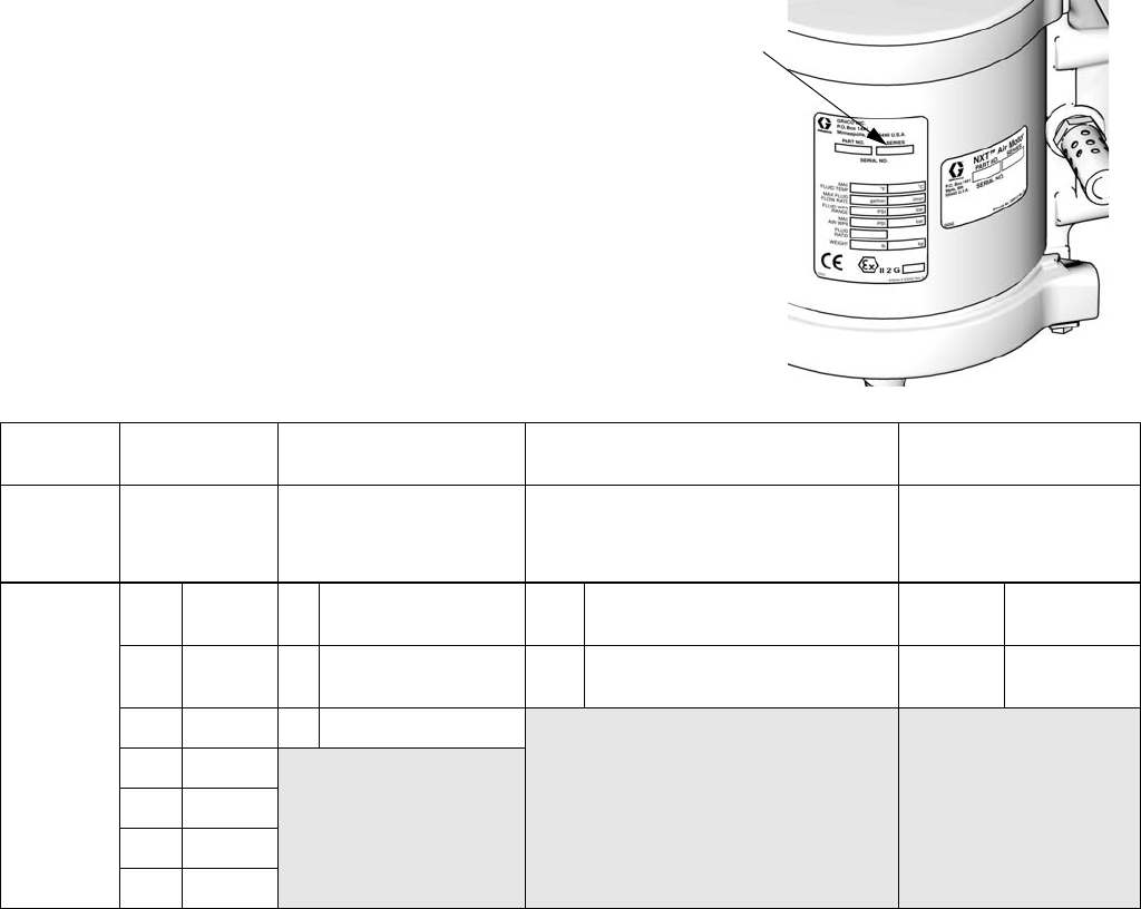
Models
6312795E
Models
Check your pump’s identification marking (ID) for the 6-digit part number.
Use the following matrix to define the construction of your pump, based on
the six digits. For example, pump Part No. B05FA0 represents a 5 to 1
ratio, 150 cc pump, with no DataTrak, a low noise exhaust, and v-packings
To order replacement parts, see Parts section starting on page 22. The
digits in the matrix do not correspond to the reference numbers in the
Parts drawings and lists.
* Cycle refers to combination of one upstroke and one downstroke.
ID
ti12922a
B05 F A 0
First
Digit
Second and
Third Digit
(Ratio)
Fourth Digit
(Displacement Pump
Volume Per Cycle)
Fifth Digit
(Smarts/Exhaust)
Sixth Digit
(Packings)
B
(Bellows
style)
05 5:1 B50 cc ANo DataTrak,
low noise exhaust 0V-packings
12 12:1 D100 cc BDataTrak Compatible,
low noise exhaust 1U-cup
packings
15 15:1 F150 cc
23 23:1
24 24:1
25 25:1
35 35:1

Pump Data
312795E 7
Pump Data
Model, Series
Air
Motor
Displacement
Pump
Maximum Fluid
Working Pressure
psi (MPa, bar)
Flow Rate
at 60 cpm
gpm (lpm) Fluid Inlet
Fluid
Outlet Air Inlet
B05FA0, Series A M04LN0 LB150A
500 (3.4, 34) 2.4 (9.0) 1 in. npt 3/4 in. npt 1/4 in. npt
B05FB0, Series A M04LT0
B05FA1, Series A M04LN0 LB150B
B05FB1, Series A M04LT0
B12DA0, Series A M07LN0 LB100A
1200 (8.3, 83) 1.6 (6.0) 3/4 in. npt 3/8 in. npt 1/2 in. npt
B12DB0, Series A M07LT0
B12DA1, Series A M07LN0 LB100B
B12DB1, Series A M07LT0
B15BA0, Series A M04LN0 LB050A
1500 (10.3, 103) 0.8 (3.0) 3/4 in. npt 3/8 in. npt 1/4 in. npt
B15BB0, Series A M04LT0
B15BA1, Series A M04LN0 LB050B
B15BB1, Series A M04LT0
B15FA0, Series A M12LN0 LB150A
1500 (10.3, 103) 2.4 (9.0) 1 in. npt 3/4 in. npt 1/2 in. npt
B15FB0, Series A M12LT0
B15FA1, Series A M12LN0 LB150B
B15FB1, Series A M12LTO
B23DA0, Series A M12LN0 LB100A
2300 (15.9, 159) 1.6 (6.0) 3/4 in. npt 3/8 in. npt 1/2 in. npt
B23DB0, Series A M12LT0
B23DA1, Series A M12LN0 LB100B
B23DB1, Series A M12LTO
B24FA0, Series A M18LN0 LB150A
2400 (16.5, 165) 2.4 (9.0) 1 in. npt 3/4 in. npt 1/2 in. npt
B24FB0, Series A M18LT0
B24FA1, Series A M18LN0 LB150B
B24FB1, Series A M18LT0
B25BA0, Series A M07LN0 LB050A
2500 (17.2, 172) 0.8 (3.0) 3/4 in. npt 3/8 in. npt 1/2 in. npt
B25BB0, Series A M07LT0
B25BA1, Series A M07LN0 LB050B
B25BB1, Series A M07LT0
B35DA0, Series A M18LN0 LB100A
3500 (24.1, 241) 1.6 (6.0) 3/4 in. npt 3/8 in. npt 1/2 in. npt
B35DB0, Series A M18LT0
B35DA1, Series A M18LN0 LB100B
B35DB1, Series A M18LT0
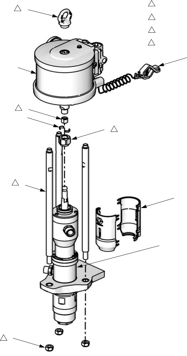
Component Identification
8312795E
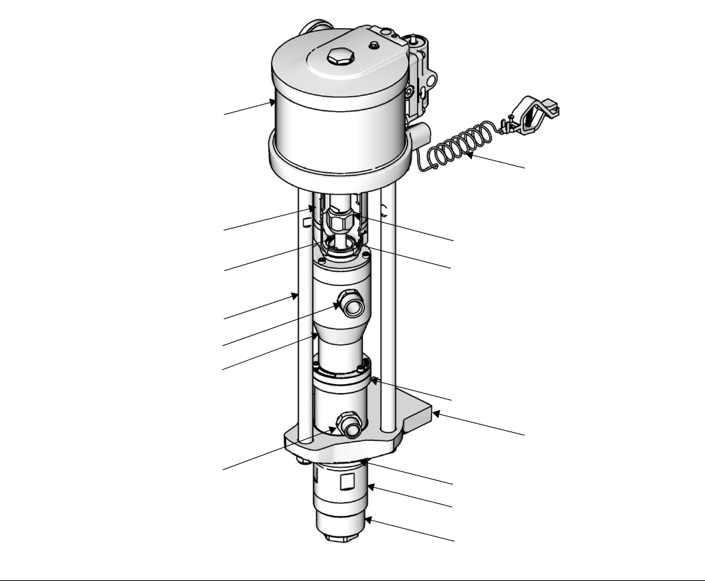
Component Identification
Key:
A Air Motor
B Coupler Shield
C Connecting Rod
D Tie Rod
E Fluid Inlet
F Bellows Chamber
G Fluid Outlet
H Ground Wire
J Coupling Nut
K Coupling Collar
L Packing Nut
M Pump Adapter
NJam Nut
P Cylinder
RFoot Cap
FIG. 1. Component Identification
A
D
E
L
M
F
G
K
C
J
B
H
N
P
Rti15361a

Component Identification
312795E 9
Installation
10 312795E
Installation
General Information
NOTE: Reference numbers and letters in parentheses in
the text refer to the callouts in the figures and the parts
drawing.
NOTE: Always use Genuine Graco Parts and Accesso-
ries, available from your Graco distributor. If you supply
your own accessories, be sure they are adequately
sized and pressure-rated for your system.
FIG. 2 and FIG. 3 are only guides for selecting and
installing system components and accessories. Contact
your Graco distributor for assistance in designing a sys-
tem to suit your particular needs.
Prepare the Operator
All persons who operate the equipment must be trained
in the operation of all system components as well as the
proper handling of all fluids. All operators must thor-
oughly read all instruction manuals, tags, and labels
before operating the equipment.
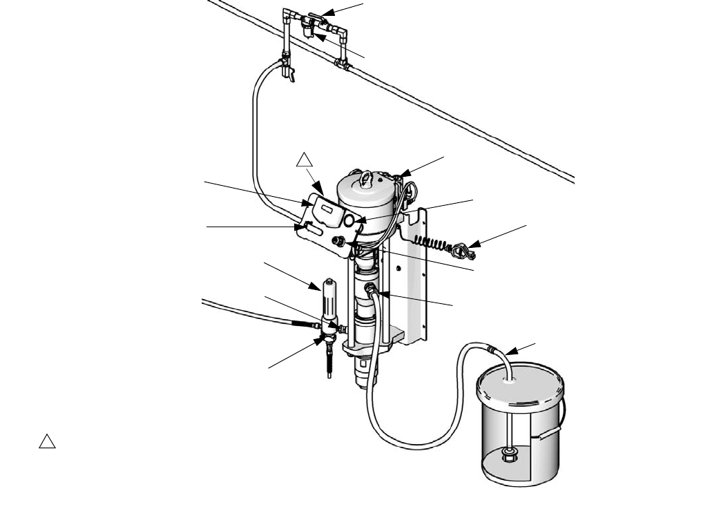
FIG. 2: Typical Wall-Mount Installation
ti15363a
A
B
E
F
G
H
J
S
T
U
P
V
R
1
Use alternate mounting holes (on bracket, not
visible) to mount air controls vertically.
1
Installation
312795E 11
Prepare the Site
Ensure that you have an adequate compressed air
supply.
Bring a compressed air supply line from the air com-
pressor to the pump location. Be sure all air hoses are
properly sized and pressure-rated for your system. Use
only electrically conductive hoses.
Keep the site clear of any obstacles or debris that could
interfere with the operator's movement.
Have a grounded, metal pail available for use when
flushing the system.
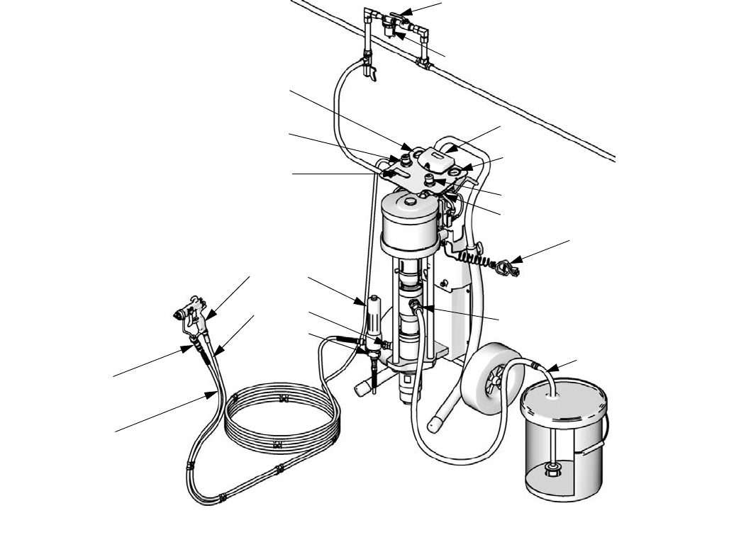
Key:
A Air Shutoff Valve
B Air Filter (optional accessory)
C Gun Air Pressure Gauge
D Gun Air Pressure Regulator
E Bleed Type Master Air Valve
F DataTrak
G Pump Air Pressure Gauge
H Pump Air Pressure Regulator
J Solenoid Release Button
(not visible)
KGun Swivel
L Air-Assisted Spray Gun
M Gun Fluid Supply Hose
N Gun Air Supply Hose
P Fluid Filter
R Pump Fluid Outlet
S Grounding Wire
T Pump Fluid Inlet
U Suction Hose
V Fluid Drain Valve
FIG. 3: Typical Cart-Mount Installation
ti15362a
A
B
C
D
E
F
G
H
J
K
M
L
N
S
T
U
P
V
R
Installation
12 312795E
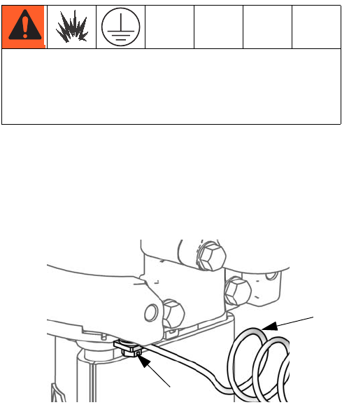
Grounding
Pump: See FIG. 4. Verify that the ground screw (GS) is
attached and tightened securely to the air motor. Con-
nect the other end of the ground wire (S) to a true earth
ground.
Air and fluid hoses: Static electricity may build up
when fluids flow through pumps, hoses, and sprayers. At
least one hose must be electrically conductive, with a
maximum of 500 ft. (150 m) combined hose length to
ensure grounding continuity. Check electrical resistance
of hose. If total resistance to ground exceeds 25 meg-
ohms, replace hose immediately.
Air compressor: follow manufacturer’s recommenda-
tions.
Spray gun / Dispense valve: Ground the spray gun
through connection to a Graco-approved grounded fluid
hose.
Fluid supply container: follow local code.
Object being sprayed: follow local code.
Solvent pails used when flushing: follow local code.
Use only conductive metal pails, placed on a grounded
surface. Do not place the pail on a nonconductive sur-
face, such as paper or cardboard, which interrupts
grounding continuity.
To maintain grounding continuity when flushing or
relieving pressure: hold metal part of the spray
gun/dispense valve firmly to the side of a grounded
metal pail, then trigger the gun/valve.
Mount the Pump
Mount the pump directly to the wall (order Wall Mounting
Kit, page 24) or to a Graco cart (order Cart Mounting Kit
24E879). Pump dimensions are shown on page 30.
Wall-Mounted Pumps
1. Be sure the wall can support the weight of the
pump, bracket, hoses and accessories, as well as
the stress caused during operation.
2. Position the wall bracket about 1.2-1.5 m (4-5 ft)
above the floor. For ease of operation and service,
make sure the pump air inlet, fluid inlet, and fluid
outlet ports are easily accessible.
3. Using the wall bracket as a template, drill 10 mm
(0.4 in.) mounting holes in the wall. Wall mounting
dimensions are shown on page 31.
4. Attach the bracket to the wall. Use 9 mm (3/8 in.)
screws that are long enough to keep the pump from
vibrating during operation.
NOTE: Be sure the pump is level.
Cart-Mounted Pumps
Kit 24E885 is available if you plan to bolt your cart to the
floor. It includes two spacers that keep the legs stable.
Bolts not included.
Air and Fluid Hoses
Be sure all air hoses (N) and fluid hoses (M) are prop-
erly sized and pressure rated for your system. See FIG.
3. Use only electrically conductive fluid hoses.
The equipment must be grounded. Grounding
reduces the risk of static and electric shock by pro-
viding an escape wire for the electrical current due to
static build up or in the event of a short circuit.
FIG. 4. Ground the Pump.
S
GS ti12914a

Installation
312795E 13
Accessories
Install the following accessories in the order shown in
FIG. 2 or FIG. 3, using adapters as necessary.
Air Line
•Bleed-type master air valve (E): required in your
system to relieve air trapped between it and the air
motor and gun when the valve is closed. Do not
block access to the valve.
Be sure the valve is easily accessible from the pump
and located downstream from the air regulator.
•Pump air regulator (H): controls pump speed and
outlet pressure. Locate it close to the pump.
•Air line filter (B): removes harmful dirt and mois-
ture from compressed air supply.
•Air shutoff valve (A): isolates air line accessories
for servicing. Locate upstream from all other air line
accessories.
•Gun air regulator (D): controls air pressure to the
air-assisted spray gun.
Fluid Line
•Fluid filter (P): with a 60 mesh (250 micron) stain-
less steel element to filter particles from the fluid as
it leaves the pump.
•Fluid drain valve (V): required in your system, to
relieve fluid pressure in the hose and gun.
•Gun or valve (L): dispenses the fluid. The gun
shown in FIG. 3 is an air-assisted spray gun for light
to medium viscosity fluids.
•Fluid line swivel (K): for easier gun movement.
•Suction kit (U): enables the pump to draw fluid
from a container.
Trapped air can cause the pump to cycle unexpectedly,
which could result in serious injury from splashing or
moving parts.
Operation
14 312795E
Operation
Pressure Relief Procedure
1. Lock the gun trigger.
2. Close the bleed-type master air valve.
3. Unlock the gun trigger.
4. Hold a metal part of the gun firmly to a grounded
metal pail. Trigger the gun to relieve pressure.
5. Lock the gun trigger.
6. Open all fluid drain valves in the system, having a
waste container ready to catch drainage. Leave
drain valve(s) open until you are ready to spray
again.
7. If you suspect that pressure has not been fully
relieved after following the steps above, check the
following:
a. The spray tip may be completely clogged. Very
slowly loosen the air cap retaining ring to relieve
pressure in the cavity between the ball/seat
shutoff and the plugged tip. Clear the tip orifice.
b. The gun fluid filter or the fluid hose may be com-
pletely clogged. Very slowly loosen the hose
end coupling at the gun and relieve pressure
gradually. Then loosen completely to clear the
obstruction.
c. After following the steps above, if the spray tip
or hose still seems completely clogged, very
slowly loosen the tip guard retaining nut or hose
end coupling and relieve pressure gradually,
then loosen completely. With tip removed, trig-
ger gun into waste container.
Flush the Pump Before First Use
The pump is tested with lightweight oil, which is left in to
protect the pump parts. If the fluid you are using may be
contaminated by the oil, flush it out with a compatible
solvent. See Flushing, page 16.
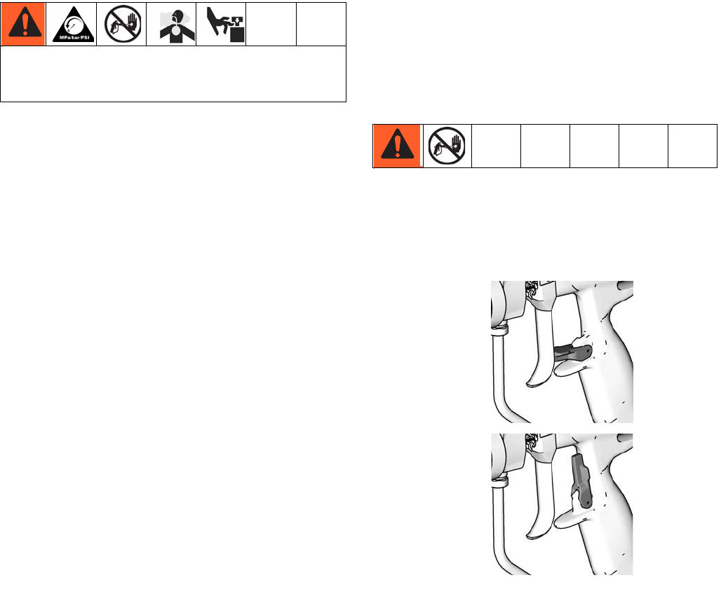
Trigger Lock
Always engage the trigger lock when you stop spraying
to prevent the gun from being triggered accidentally by
hand or if dropped or bumped.
Trapped air can cause the pump to cycle unexpectedly,
which could result in serious injury from splashing or
moving parts.
FIG. 5. Gun Trigger Lock
ti6581b
ti6582b
Gun Trigger
Locked
Gun Trigger
Unlocked
Operation
312795E 15
Prime and Adjust the Pump
1. Lock gun trigger. Remove tip guard and spray tip
from gun. Refer to gun manual.
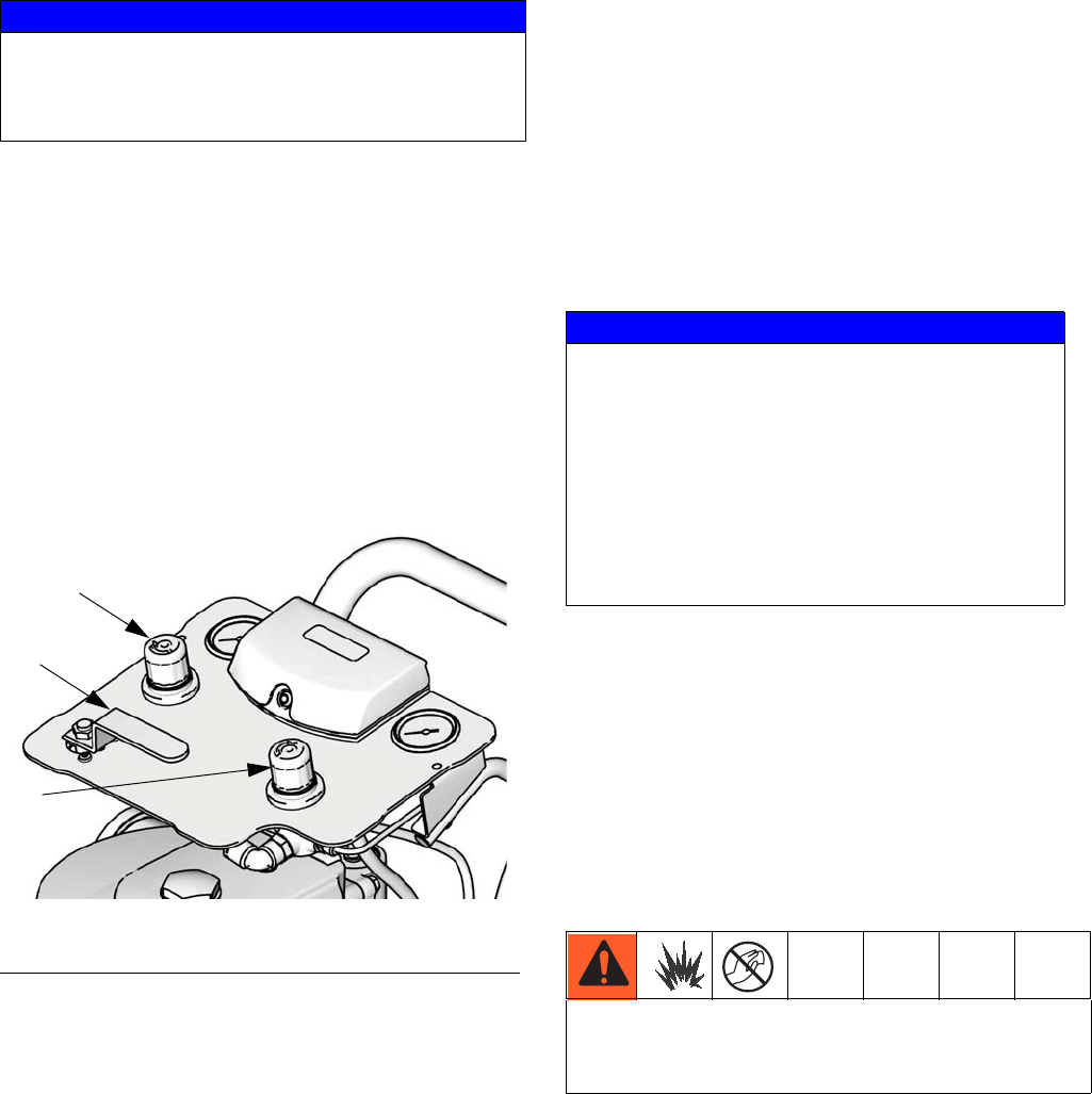
2. Close gun air regulator (D) and pump air regulator
(H) by turning knobs counterclockwise reducing
pressure to zero. Close bleed-type air valve (E).
Also verify that all drain valves are closed.
3. Check that all fittings throughout system are tight-
ened securely.
4. Position pail close to pump. Do not stretch suction
hose tight; let it hang to assist fluid flow into pump.
5. Hold metal part of gun (L) firmly to side of grounded
metal pail, unlock trigger, and hold trigger open.
6. Open bleed-type air valve (E). Slowly open the
pump air regulator (H) until the pump starts.
7. Cycle pump slowly until all air is pushed out and the
pump and hoses are fully primed.
8. Release the gun trigger and engage the trigger lock.
Pump should stall against pressure.
9. In a direct supply system, with the pump and lines
primed, and with adequate air pressure and volume
supplied, the pump will start and stop as the
gun/valve is opened and closed.
10. In a circulating system, the pump runs continuously
and speeds up or slows down as the system
demands until the air supply is shut off.
11. Use the air regulator to control the pump speed and
the fluid pressure. Always use the lowest air pres-
sure necessary to get the desired results. Higher
pressures cause premature tip/nozzle and pump
wear.
Shutdown and Care of the Pump
For a brief shutdown, relieve the pressure, page 14.
For a longer shutdown, or overnight, always flush the
pump, page 16, and relieve the pressure, page 14.
NOTE: If the overflow chamber (optional accessory)
contains fluid, unscrew the bottle (103) and discard. If it
has not been used, the bottle can remain attached to the
cap.
NOTICE
The maximum fluid inlet pressure is 15 psi (0.1 MPa,
1.0 bar). Damage to the bellows may occur if you
exceed this pressure. Do not use another pump or
checking device to supply the bellows pump.
FIG. 6. Air Controls
D
E
H
ti15364a
NOTICE
Never allow the pump to run dry of the fluid being
pumped. A dry pump quickly accelerates to a high
speed, possibly damaging itself. If your pump accel-
erates quickly, or is running too fast, stop it immedi-
ately and check the fluid supply. If the supply
container is empty and air has been pumped into
the lines, refill the container and prime the pump
and the lines with fluid, or flush and leave it filled
with a compatible solvent. Be sure to eliminate all
air from the fluid system.
To avoid the buildup of static charge, do not rub the
plastic bottle with a dry cloth while it is attached to
the pump. Remove the bottle to clean, if needed.

Maintenance
16 312795E
Maintenance
Preventive Maintenance
Schedule
The operating conditions of your particular system
determine how often maintenance is required. Establish
a preventive maintenance schedule by recording when
and what kind of maintenance is needed, and then
determine a regular schedule for checking your system.
Tighten Threaded Connections
Before each use, check all hoses for wear or damage.
Replace as necessary. Check that all threaded connec-
tions are tight and leak-free.
Flushing
Flush the pump:
• Before first use
• When changing colors or fluids
• Before repairing equipment
• Before fluid dries or settles out in a dormant pump
(check the pot life of catalyzed fluids)
• At the end of the day
• Before storing the pump.
Flush at the lowest pressure possible. Flush with a fluid
that is compatible with the fluid you are pumping and
with the wetted parts in your system. Check with your
fluid manufacturer or supplier for recommended flushing
fluids and flushing frequency.
1. Follow Pressure Relief Procedure, page 14.
2. Remove tip guard and spray tip from gun. Refer to
separate gun manual.
3. Place siphon tube in grounded metal pail containing
cleaning fluid.
4. Set pump to lowest possible fluid pressure, and start
pump.
5. Hold a metal part of the gun firmly to a grounded
metal pail.
6. Trigger gun. Flush system until clear solvent flows
from gun.
7. Follow Pressure Relief Procedure, page 14.
8. Clean the tip guard, spray tip, and fluid filter element
separately, then reinstall them.
9. Clean inside and outside of suction tube.
Read all Warnings. Follow all Grounding instruc-
tions. See page 12.
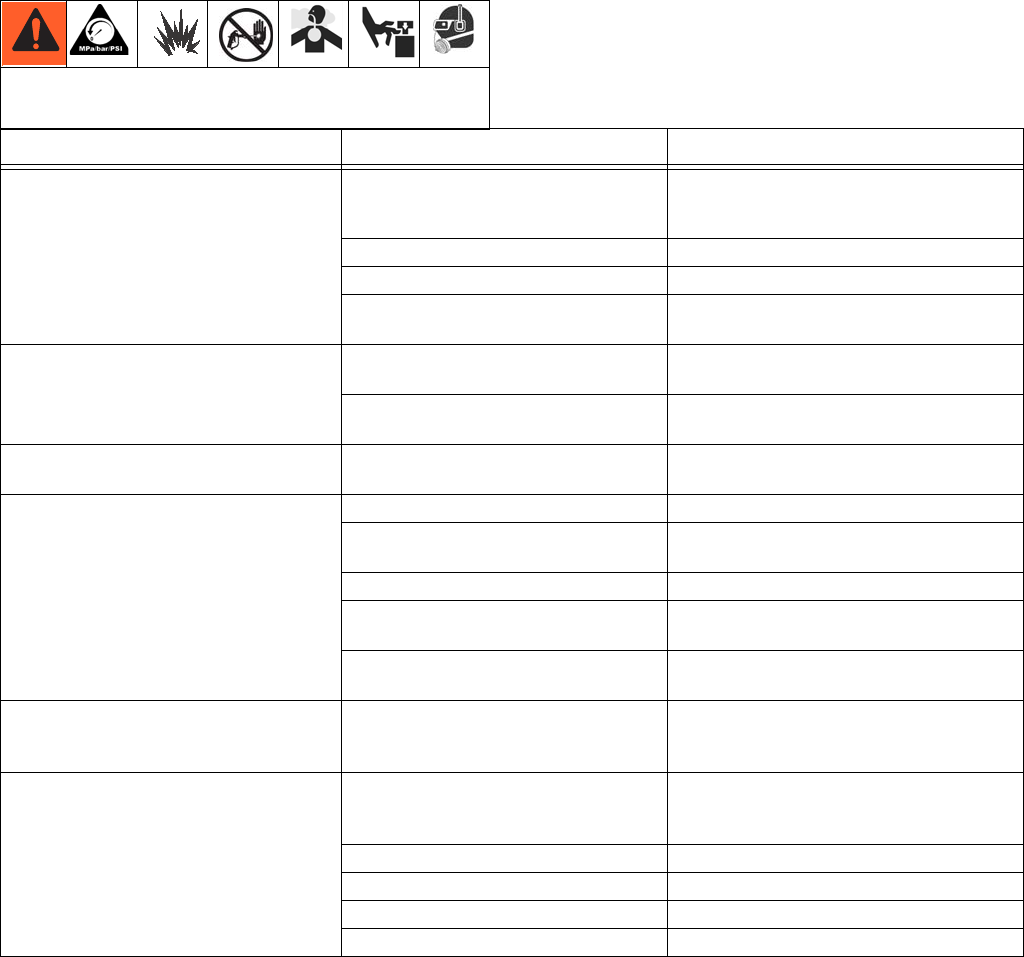
Troubleshooting
312795E 17
Troubleshooting
NOTE: Check all possible problems and causes before
disassembling the pump.
*See Related Manuals, page 2, for manual numbers.
Relieve the pressure, page 14, before checking or
servicing the equipment.
Problem Cause Solution
Pump output low on both strokes. Restricted air supply lines. Clear any obstructions; be sure all shutoff
valves are open; increase pressure, but do
not exceed maximum working pressure.
Exhausted fluid supply. Refill and reprime pump.
Clogged fluid outlet line, valves, etc. Clear.
Worn piston u-cup or v-packings. Replace. See Bellows Displacement Pump
manual.*
Pump output low on only one stroke. Held open or worn ball check valves. Check and repair. See Bellows Displace-
ment Pump manual.*
Worn piston u-cup or v-packings. Replace. See Bellows Displacement Pump
manual.*
No output. Improperly installed ball check valves. Check and repair. See Bellows Displace-
ment Pump manual.*
Pump operates erratically. Exhausted fluid supply. Refill and reprime pump.
Held open or worn ball check valves. Check and repair. See Bellows Displace-
ment Pump manual.*
Clogged suction tube or filter Clear part(s).
Worn piston u-cup or v-packings. Replace. See Bellows Displacement Pump
manual.*
Damaged bellows. Replace. See Bellows Displacement Pump
manual.*
Material visible in the overflow chamber
(if equipped) or weeping from port in
packing nut.
Damaged bellows. Replace. See Bellows Displacement Pump
manual.*
Pump will not operate. Restricted air supply lines. Clear any obstructions; be sure all shut off
valves are open; increase pressure, but do
not exceed maximum working pressure.
Exhausted fluid supply. Refill and reprime pump.
Clogged fluid outlet line, valves, etc. Clear.
Damaged air motor. See NXT Air Motor manual.*
Runaway solenoid has tripped. Retract solenoid. NXT Air Motor manual.*
Repair
18 312795E
Repair
General Information
• Reference numbers and letters in parentheses in
the text refer to the callouts in the figures and the
parts drawing.
• Always use Genuine Graco Parts and Accessories,
available from your Graco distributor. If you supply
your own accessories, be sure they are adequately
sized and pressure rated for your system.
Preparation
1. Flush the pump, if possible, page 16.
2. Stop the pump close to the middle of the stroke.
3. Follow Pressure Relief Procedure, page 14.
4. Disconnect the air and fluid hoses and the ground
wire.
5. Remove the shield.
NOTE: If the overflow chamber (optional accessory)
contains fluid, unscrew the bottle (103) and discard. If it
has not been used, the bottle can remain attached to the
cap.
Disconnect the Pump
NOTE: Follow these instructions to remove the entire
pump from the wall or cart bracket. For wall-mounted
packages, you may prefer to remove the entire pump,
even if only the air motor requires repair.
1. Follow all steps under Preparation, page 18.
2. Loosen the four mounting nuts. Use two people to
lift the entire pump up and out from the mounting
plate. Place it on a work bench.
Disconnect the Displacement Pump
1. Follow all steps under Preparation, page 18.
2. Loosen the screws on the top cap.
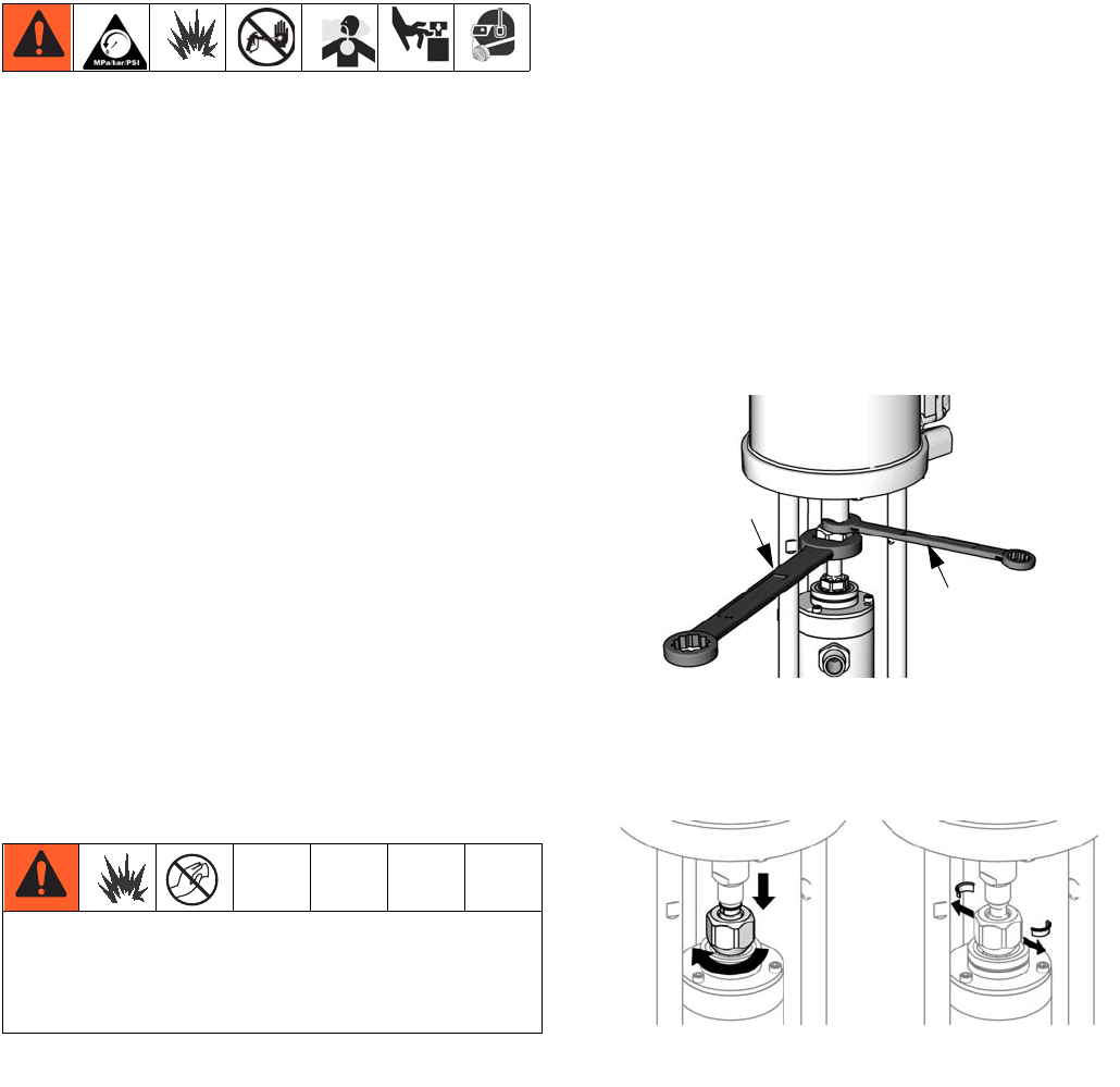
3. Hold the coupling nut (7) with a wrench. Use
another wrench to turn the motor shaft. To avoid
damage to the bellows top cap and the D-shaped
seal, do not turn the coupling nut.
4. Lower the coupling nut (7) and remove the coupling
collars (5).
To avoid the buildup of electrostatic charge, do not
rub the plastic bottle with a dry cloth while it is
attached to the pump. Remove the bottle to clean, if
needed.
FIG. 7. Loosen the coupling nut.
FIG. 8. Remove coupling collars.
hold
turn
ti14531a
ti15365a
Repair
312795E 19
5. Push up the motor shaft. Remove the coupling
nut (7).
6. Use a socket to remove the tie rod nuts (4).
7. Use a socket to remove the bottom two mounting
screws.
8. Carefully remove the displacement pump, with the
pump adapter attached.
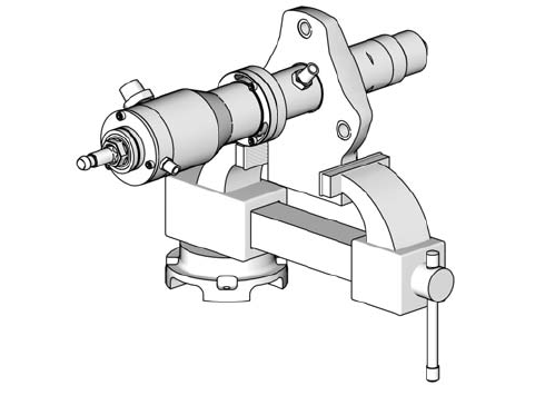
9. Clamp the adapter plate in a vise to service the dis-
placement pump.
10. See your displacement pump manual for service
and parts information.
Disconnect the Air Motor
1. Follow all steps under Preparation, page 18.
2. Loosen the screws on the top cap.
3. Hold the coupling nut (7) with a wrench. Use
another wrench to turn the motor shaft. To avoid
damage to the bellows top cap and the D-shaped
seal, do not turn the coupling nut. See FIG. 7.
4. Lower the coupling nut (7) and remove the coupling
collars (5). See FIG. 8.
5. Push up the motor shaft. Remove the coupling
nut (7).
6. Use a socket to remove the tie rod nuts (4).
7. Use a socket to remove the top two mounting
screws.
8. Lift up on the air motor to remove it. The tie rods (3)
will remain attached.
NOTE: For cart mount pumps, remove the two screws
on the arms and tip back or remove the air control panel
for easier removal of the air motor.
9. Use a socket on the flats of the tie rods (3) to
remove them from the bottom cover of the air motor.
NOTE: See your air motor manual for service and parts
information.
FIG. 9
ti14537a
Repair
20 312795E
Reconnect the Air Motor
1. Screw the tie rods (3) into the bottom cover of the air
motor. Torque to 50-55 ft-lb (68-75 N•m).
2. As needed for the larger air motors, use two people
to reattach. Align the tie rods (3) with the holes in
the pump adapter. Carefully lower the air motor into
place.
3. Attach the tie rod nuts (4) and torque to 50-60 ft-lb
(68-81 N•m).
4. Tighten the mounting screws.
5. Hold the motor shaft up with one hand. With your
other hand, put the coupling nut (7) on the displace-
ment rod.
6. Put the coupling collars (5) into the coupling nut (7)
so large flanges point upward.
7. Gently let the motor shaft drop onto the displace-
ment rod. Torque the coupling nut (7) to 75-80 ft-lb
(138-146 N•m).
8. Connect the air and fluid hoses, the ground wire,
and the shield.
Reconnect the Displacement Pump
1. Align the straight edge of the pump adapter with the
back of the air motor. Slide the pump adapter onto
the tie rods (3).
2. Attach the tie rod nuts (4) and torque to 50-60 ft-lb
(68-81 N•m).
3. Tighten the mounting screws.
4. Hold the motor shaft up with one hand. With your
other hand, put the coupling nut (7) on the displace-
ment rod.
5. Put the coupling collars (5) into the coupling nut (7)
so large flanges point upward.
6. Gently let the motor shaft drop onto the displace-
ment rod. Torque the coupling nut (7) to 75-80 ft-lb
(138-146 N•m).
7. Connect the air and fluid hoses, the ground wire,
and the shield.
Reconnect the Pump
NOTE: If the entire pump has been removed and is now
reassembled, follow these directions:
1. Use two people to lift the pump into place. Slide it in
and down onto the mounting plate.
2. Tighten the mounting screws.
3. Connect the air and fluid hoses, the ground wire,
and the shield.

Repair
312795E 21
Parts
22 312795E
Parts
Torque to 50-55 ft-lb (68-75 N•m).
1
1
2
3
4
7
5
8
Torque to 50-60 ft-lb (68-81 N•m).
2
Torque to 75-80 ft-lb (138-146 N•m).
3
3
2
1
10
2
ti15367a
9
6
4
M04xxx air motors only; counterbore
end faces motor.
4

Parts
312795E 23
Part No./Description
----- Not sold separately.
* Included in Connecting Kit. See page 23 to order the
correct kit for your pump.
▲Replacement Danger and Warning labels, tags, and
cards are available at no cost.
Parts That Vary by Model
Ref.
No. Part No. Description Qty.
1 See Table DISPLACEMENT PUMP, see
manual 312793 for parts
1
2 See Table MOTOR, see manual 312796 for
parts
1
3* 15U691 TIE ROD 3
4* 15U606 NUT, tie rod 3
5* 184128 COLLAR, coupling; see page 23
for package of 10
2
6* See Table ADAPTER, used with air motor
M04xxx
1
7* 15T311 NUT, coupling 1
8* 24A640 SHIELD, coupler Set
of 2
9 238909 WIRE, grounding assembly 1
10 24E992 LIFT RING, with o-ring 1
11▲290079 TAG, warning, grounding, not
shown
1
12▲15W718 LABEL, warning, not shown 1
13▲15W719 LABEL, warning, not shown 1
Model
Displacement
Pump (1)
Motor
(2)
Motor
Piston
Diam.
(in.)
Adapter
(6)
B05FA0 LB150A M04LN0
3.5 15M675
B05FB0 M04LT0
B05FA1 LB150B M04LN0
B05FB1 M04LT0
B12DA0 LB100A M07LN0
4.5
B12DB0 M07LT0
B12DA1 LB100B M07LN0
B12DB1 M07LT0
B15BA0 LB050A M04LN0
3.5 15M675
B15BB0 M04LT0
B15BA1 LB050B M04LN0
B15BB1 M04LT0
B15FA0 LB150A M12LN0
6.0
B15FB0 M12LT0
B15FA1 LB150B M12LN0
B15FB1 M12LT0
B23DA0 LB100A M12LN0
6.0
B23DB0 M12LT0
B23DA1 LB100B M12LN0
B23DB1 M12LT0
B24FA0 LB150A M18LN0
7.5
B24FB0 M18LT0
B24FA1 LB150B M18LN0
B24FB1 M18LT0
B25BA0 LB050A M07LN0
4.5
B25BB0 M07LT0
B25BA1 LB050B M07LN0
B25BB1 M07LT0
B35DA0 LB100A M18LN0
7.5
B35DB0 M18LT0
B35DA1 LB100B M18LN0
B35DB1 M18LT0
Repair Kits
24 312795E
Repair Kits
NOTE: For displacement pump repair kits, see manual 312793. For air motor repair kits, see manual 312796.
Wall Mounting Kits
Includes bracket and hardware.
Cart Mounting Kit 24E879
Includes cart, bracket, and hardware.
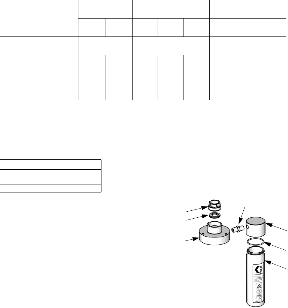
Accessories
Overflow Chamber Kit 24E298
Kit includes overflow cup with cap, seals and necessary
hardware. Parts not sold separately.
Kit Description
LB050A and
LB050B LB100A and LB100B LB150A and LB150B
3.5 in.
motor
4.5 in.
motor
4.5 in.
motor
6.0 in.
motor
7.5 in.
motor
3.5 in.
motor
6.0 in.
motor
7.5 in
motor
Coupling Collars (5)
Package of 10 24A619 24A619 24A619
Connecting Kit
Includes three tie rods (3),
three tie rod nuts (4), air motor
adapter, if needed (6),
coupling nut (7), two coupling
collars (5), and two shields (8)
24A291 24A294 24A294 24A294 24A294 24A291 24A294 24A294
Kit Air Motor on Pump
24A880 M04xxx
24A881 M07xxx
24A882 M12xxx or M18xxx
Ref. Description Qty.
101 LID 1
102 O-RING 1
103 BOTTLE 1
104 FITTING, 2 x 1/4-18 npt 1
105 NUT, retaining 1
106 D-SHAPED SEAL, bellows 1
ti15254a
103
101
106
105
104
102
Top Cap

Repair Kits
312795E 25
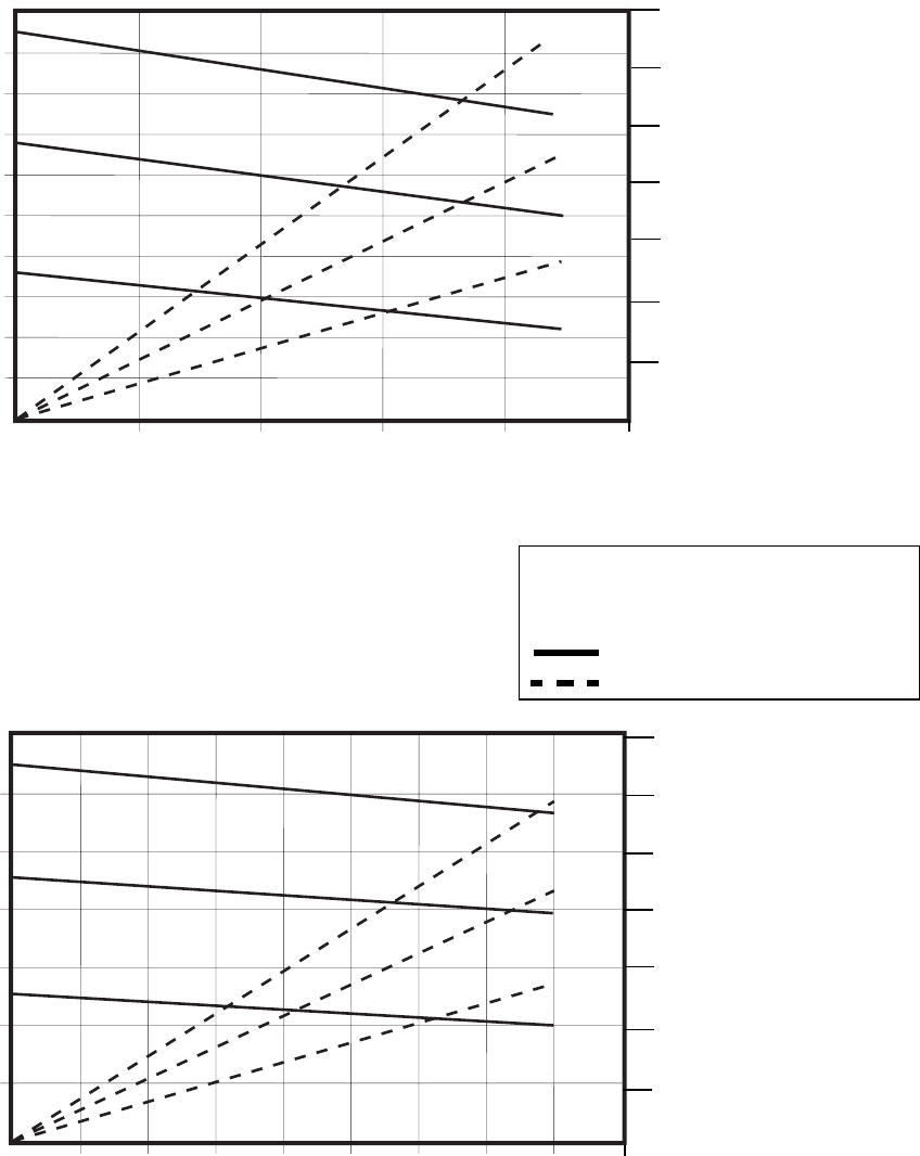
Performance Charts
26 312795E
Performance Charts
Cycles per Minute
0
0
Fluid Flow gpm (lpm) tested in No. 10 weight oil
Fluid Outlet Pressure psi (MPa, bar)
Air Flow scfm (m3/min)
Model B05Fxx
5:1 Ratio, 150cc/cycle
KEY
A
=
100 psi (0.7 MPa, 7 bar)
B
=
70 psi (0.5 MPa, 5 bar)
C
=
40 psi (0.3 MPa, 3 bar)
= fluid flow
= air consumption
100
(0.7, 7)
200
(1.4, 14)
300
(2.1, 21)
400
(2.8, 28)
500
(3.5, 35)
0.5
(1.9)
1.0
(3.8)
1.5
(5.7)
2.5
(9.5)
2.0
(7.6)
A
B
C
A
B
C
14
(0.4
12
(0.34)
10
(0.28)
8
(0.23)
6
(0.17)
4
(0.11)
2
(0.06)
Model B12Dxx
12:1 Ratio, 100cc/cycle
Fluid Outlet Pressure psi (MPa, bar)
Air Flow scfm (m3/min)
0
0
200
(1.4, 14)
600
(4.1, 41)
1000
(6.9, 69)
1400
(9.7, 97) A
B
C
A
B
C
35
(0.99)
30
(0.85)
25
(0.71)
20
(0.57)
15
(0.42)
10
(0.28)
5
(0.14)
Cycles per Minute
Fluid Flow gpm (lpm) tested in No. 10 weight oil
0.2
(0.8)
0.6
(2.3)
1.0
(3.8)
1.4
(5.3)
1.8
(6.8)
13 25 38 51 63
82338536115 30 45
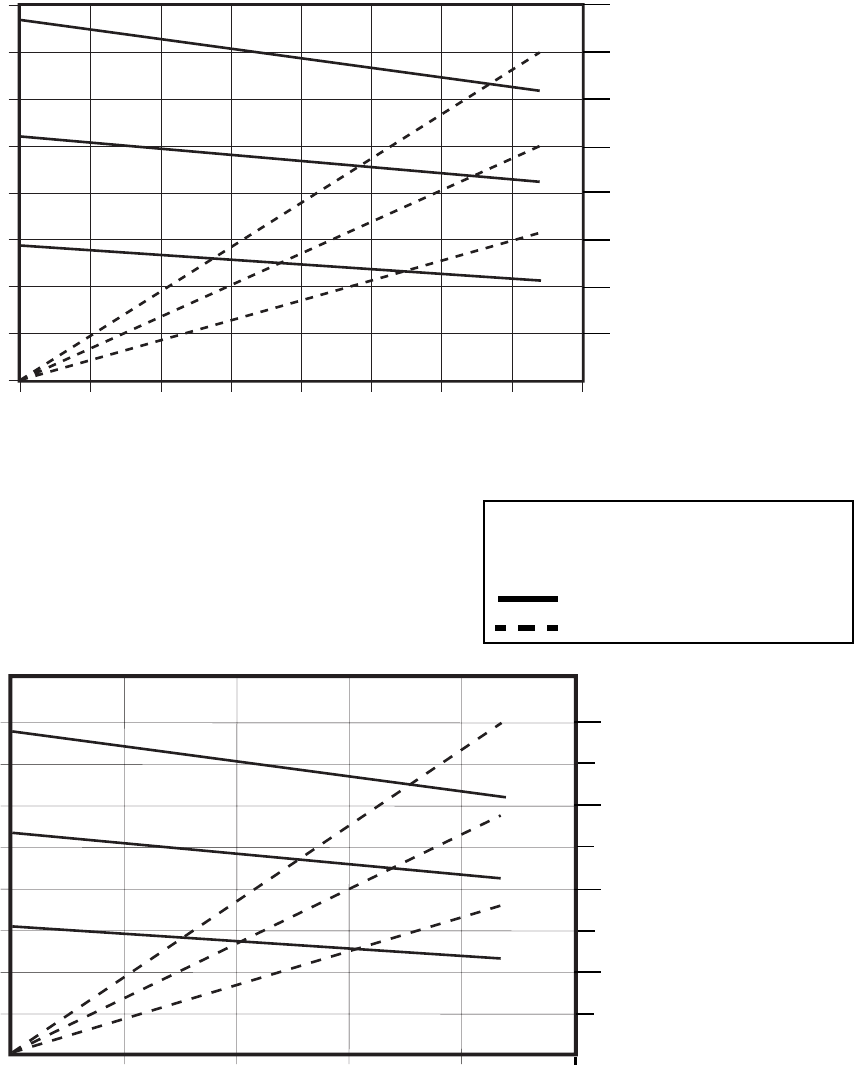
Performance Charts
312795E 27
Cycles per Minute
Fluid Flow gpm (lpm) tested in No. 10 weight oil
Fluid Outlet Pressure psi (MPa, bar)
Air Flow scfm (m3/min)
KEY
A
=
100 psi (0.7 MPa, 7 bar)
B
=
70 psi (0.5 MPa, 5 bar)
C
=
40 psi (0.3 MPa, 3 bar)
= fluid flow
= air consumption
Cycles per Minute
Fluid Flow gpm (lpm) tested in No. 10 weight oil
Fluid Outlet Pressure psi (MPa, bar)
Air Flow scfm (m3/min)
0
0
Model B15Fxx
15:1 Ratio, 150cc/cycle
400
(2.8, 28)
800
(5.5, 55)
1200
(8.3, 83)
1600
(11.0, 110)
0.5
(1.9)
1.0
(3.8)
1.5
(5.7)
2.5
(9.5)
2.0
(7.6)
A
B
C
A
B
C
40
(1.13)
30
(0.85)
20
(0.57)
10
(0.28)
Model B15Bxx
15:1 Ratio, 50cc/cycle
400
(2.8, 28)
800
(5.5, 55)
1200
(8.3, 83)
1600
(11.0, 110) 14 (0.40)
12 (0.34)
10 (0.28)
8 (0.23)
6 (0.17)
4 (0.11)
2 (0.06)
16 (0.45)
0.2
(0.8)
0.4
(1.5)
0.6
(2.3)
0.8
(3.0)
0
0
A
B
C
A
B
C
82338536115 30 45
25 38 51 6313
Performance Charts
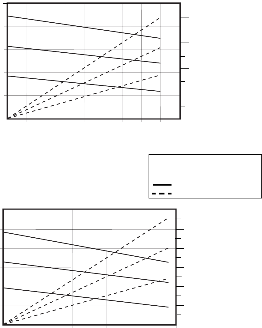
28 312795E
Cycles per Minute
Fluid Flow gpm (lpm) tested in No. 10 weight oil
Fluid Outlet Pressure psi (MPa, bar)
Air Flow scfm (m3/min)
KEY
A
=
100 psi (0.7 MPa, 7 bar)
B
=
70 psi (0.5 MPa, 5 bar)
C
=
40 psi (0.3 MPa, 3 bar)
= fluid flow
= air consumption
Cycles per Minute
Fluid Flow gpm (lpm) tested in No. 10 weight oil
Fluid Outlet Pressure psi (MPa, bar)
Air Flow scfm (m3/min)
0
0
A
B
C
A
B
C
Model B23Dxx
23:1 Ratio, 100 cc/cycle
500
(3.4, 34)
1000
(6.9, 69)
1500
(10.3, 103)
2000
(13.8, 138)
2500
(17.2, 172)
0.2
(0.8)
0.6
(2.3)
1.0
(3.8)
1.4
(5.3)
1.8
(6.8)
40
(1.13)
30
(0.85)
20
(0.57)
10
(0.28)
0
0
Model B24Fxx
24:1 Ratio, 150cc/cycle
0.5
(1.9)
1.0
(3.8)
1.5
(5.7)
2.5
(9.5)
2.0
(7.6)
A
B
C
A
B
C
40
(1.13)
30
(0.85)
20
(0.57)
10
(0.28)
500
(3.4, 34)
1000
(6.9, 69)
1500
(10.3, 103)
2000
(13.8, 138)
2500
(17.2, 172)
3000
(20.7, 207)
50
(1.42)
60
(1.70)
82338536115 30 45
25 38 51 6313
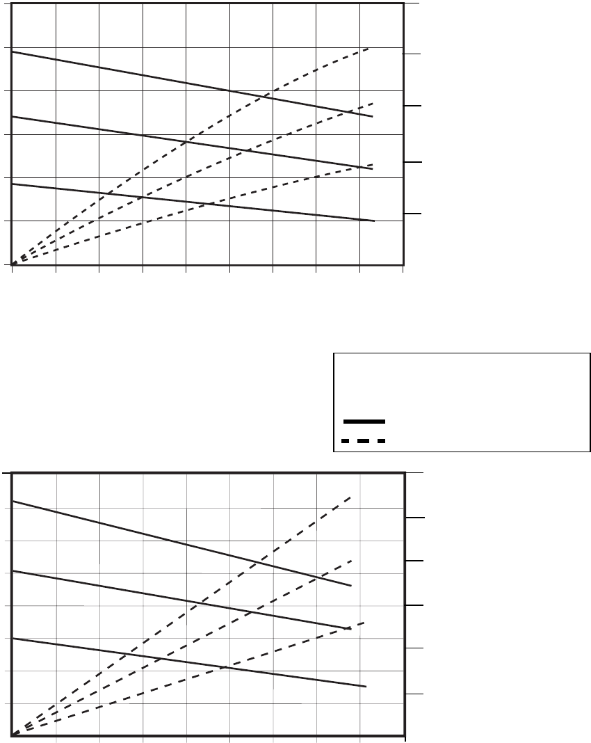
Performance Charts
312795E 29
Cycles per Minute
Fluid Flow gpm (lpm) tested in No. 10 weight oil
Fluid Outlet Pressure psi (MPa, bar)
Air Flow scfm (m3/min)
KEY
A
=
100 psi (0.7 MPa, 7 bar)
B
=
70 psi (0.5 MPa, 5 bar)
C
=
40 psi (0.3 MPa, 3 bar)
= fluid flow
= air consumption
Cycles per Minute
0
0
A
B
C
A
B
C
Fluid Flow gpm (lpm) tested in No. 10 weight oil
Fluid Outlet Pressure psi (MPa, bar)
Air Flow scfm (m3/min)
Model B35Dxx
35:1 Ratio, 100 cc/cycle
1000
(6.9, 69)
2000
(13.8, 138)
3000
(20.7, 207)
4000
(27.6, 276)
0.2
(0.8)
0.6
(2.3)
1.0
(3.8)
1.4
(5.3)
1.8
(6.8)
40
(1.13)
30
(0.85)
20
(0.57)
10
(0.28)
50
(1.42)
60
(1.70)
Model B25Bxx
25:1 Ratio, 50 cc/cycle
500
(3.4, 34)
1000
(6.9, 69)
1500
(10.3, 103)
2000
(13.8, 138)
2500
(17.2, 172)
3000
(20.7, 207)
0
00.2
(0.8)
0.4
(1.5) 0.6
(2.3)
0.8
(3.0)
25
(0.71)
20
(0.57)
15
(0.42)
10
(0.28)
5
(0.14)
A
B
C
A
B
C
82338536115 30 45
823 38 53 6115 30 45
Pump Dimensions
30 312795E
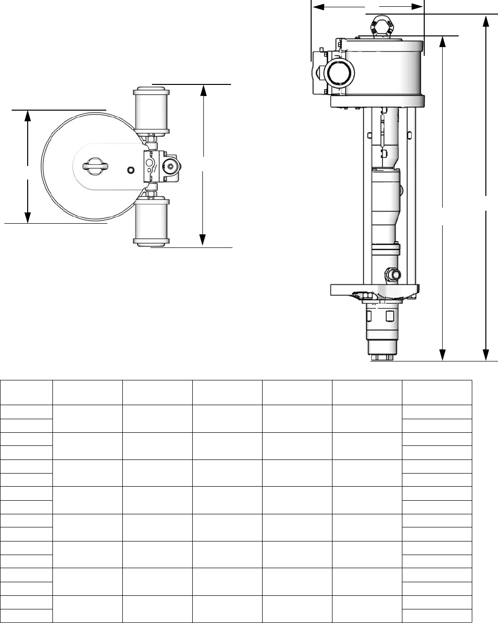
Pump Dimensions
Pump
Model A
in. (mm)
B
in. (mm)
C
in. (mm)
D
in. (mm)
E
in. (mm)
Weight
lb (kg)
B05FAx 33 (838) 6.9 (175) 5.8 (147) 9.7 (246) 35 (888) 65 (29)
B05FBx 66 (30)
B12DAx 33.5 (851) 6.9 (175) 10.8 (274) 9.7 (246) 35 (888) 71 (32)
B12DBx 72 (33)
B15BAx 33 (838) 6.9 (175) 5.8 (147) 9.7 (246) 35 (888) 56 (25)
B15BBx 57 (26)
B15FAx 33.5 (851) 8.6 (218) 11.7 (297) 11.4 (290) 35.6 (904) 82 (37)
B15FBx 83 (38)
B23DAx 33.5 (851) 8.6 (218) 11.7 (297) 11.4 (290) 35.6 (904) 78 (35)
B23DBx 79 (36)
B24FAx 33.5 (851) 10.1 (257) 14.8 (375) 12.9 (328) 35.6 (904) 85 (38)
B24FBx 86 (39)
B25BAx 33 (838) 6.9 (175) 10.8 (274) 9.7 (246) 35 (888) 62 (28)
B25BBx 63 (29)
B35DAx 33.5 (851) 10.1 (257) 14.8 (375) 12.9 (328) 35.6 (904) 81 (36)
B35DAx 82 (37)
C
B
A
D
ti15391a
ti15368a
E
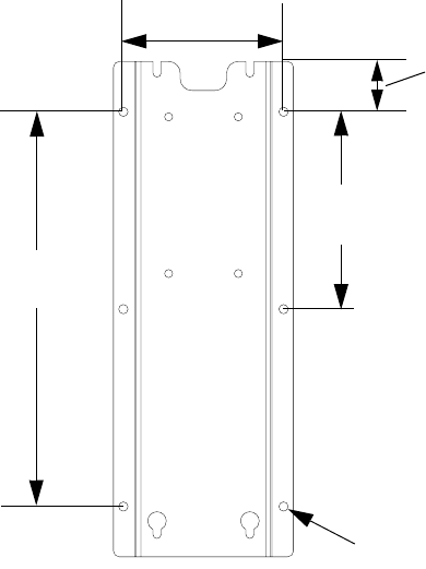
Wall Bracket Mounting Dimensions
312795E 31
Wall Bracket Mounting Dimensions
Technical Data
* See Related Manuals, page 2, for manual number.
8.5 in.
(216 mm)
17.0 in.
(432 mm)
2.167 in.
(55 mm)
6 x 0.400 in.
(10 mm)
6.9 in.
(175 mm)
ti15369a
Maximum fluid working pressure . . . . . . . . . . . . . . . . . See Pump Data, page 7.
Maximum fluid inlet pressure . . . . . . . . . . . . . . . . . . . . 15 psi (0.1 MPa, 1.0 bar)
Maximum air inlet pressure. . . . . . . . . . . . . . . . . . . . . . 100 psi (0.7 MPa, 7 bar)
Minimum air inlet pressure . . . . . . . . . . . . . . . . . . . . . . 10 psi (0.07 MPa, 0.7 bar)
Air consumption . . . . . . . . . . . . . . . . . . . . . . . . . . . . . . See , page 25.
Fluid flow at 60 cycles per minute. . . . . . . . . . . . . . . . . See Pump Data, page 7.
Maximum fluid temperature . . . . . . . . . . . . . . . . . . . . . 160°F (71°C)
Ambient temperature range . . . . . . . . . . . . . . . . . . . . . 35°–120°F (2°–49°C)
Stroke length. . . . . . . . . . . . . . . . . . . . . . . . . . . . . . . . . 2.5 in. (63.5 mm)
Sound data . . . . . . . . . . . . . . . . . . . . . . . . . . . . . . . . . . See Technical Data in NXT Air Motor manual.*
Wetted parts . . . . . . . . . . . . . . . . . . . . . . . . . . . . . . . . . PEEK, PTFE, stainless steel, tungsten carbide,
UHMWPE
All written and visual data contained in this document reflects the latest product information available at the time of publication.
Graco reserves the right to make changes at any time without notice.
Original instructions. This manual contains English. MM 312795
Graco Headquarters: Minneapolis
International Offices: Belgium, China, Japan, Korea
GRACO INC. AND SUBSIDIARIES • P.O. BOX 1441 • MINNEAPOLIS MN 55440-1441 • USA
Copyright 2010, Graco Inc. All Graco manufacturing locations are registered to ISO 9001.
www.graco.com
Revised 7/2011
Graco Standard Warranty
Graco warrants all equipment referenced in this document which is manufactured by Graco and bearing its name to be free from defects in
material and workmanship on the date of sale to the original purchaser for use. With the exception of any special, extended, or limited warranty
published by Graco, Graco will, for a period of twelve months from the date of sale, repair or replace any part of the equipment determined by
Graco to be defective. This warranty applies only when the equipment is installed, operated and maintained in accordance with Graco’s written
recommendations.
This warranty does not cover, and Graco shall not be liable for general wear and tear, or any malfunction, damage or wear caused by faulty
installation, misapplication, abrasion, corrosion, inadequate or improper maintenance, negligence, accident, tampering, or substitution of
non-Graco component parts. Nor shall Graco be liable for malfunction, damage or wear caused by the incompatibility of Graco equipment with
structures, accessories, equipment or materials not supplied by Graco, or the improper design, manufacture, installation, operation or
maintenance of structures, accessories, equipment or materials not supplied by Graco.
This warranty is conditioned upon the prepaid return of the equipment claimed to be defective to an authorized Graco distributor for verification of
the claimed defect. If the claimed defect is verified, Graco will repair or replace free of charge any defective parts. The equipment will be returned
to the original purchaser transportation prepaid. If inspection of the equipment does not disclose any defect in material or workmanship, repairs will
be made at a reasonable charge, which charges may include the costs of parts, labor, and transportation.
THIS WARRANTY IS EXCLUSIVE, AND IS IN LIEU OF ANY OTHER WARRANTIES, EXPRESS OR IMPLIED, INCLUDING BUT NOT LIMITED
TO WARRANTY OF MERCHANTABILITY OR WARRANTY OF FITNESS FOR A PARTICULAR PURPOSE.
Graco’s sole obligation and buyer’s sole remedy for any breach of warranty shall be as set forth above. The buyer agrees that no other remedy
(including, but not limited to, incidental or consequential damages for lost profits, lost sales, injury to person or property, or any other incidental or
consequential loss) shall be available. Any action for breach of warranty must be brought within two (2) years of the date of sale.
GRACO MAKES NO WARRANTY, AND DISCLAIMS ALL IMPLIED WARRANTIES OF MERCHANTABILITY AND FITNESS FOR A
PARTICULAR PURPOSE, IN CONNECTION WITH ACCESSORIES, EQUIPMENT, MATERIALS OR COMPONENTS SOLD BUT NOT
MANUFACTURED BY GRACO. These items sold, but not manufactured by Graco (such as electric motors, switches, hose, etc.), are subject to
the warranty, if any, of their manufacturer. Graco will provide purchaser with reasonable assistance in making any claim for breach of these
warranties.
In no event will Graco be liable for indirect, incidental, special or consequential damages resulting from Graco supplying equipment hereunder, or
the furnishing, performance, or use of any products or other goods sold hereto, whether due to a breach of contract, breach of warranty, the
negligence of Graco, or otherwise.
FOR GRACO CANADA CUSTOMERS
The Parties acknowledge that they have required that the present document, as well as all documents, notices and legal proceedings entered into,
given or instituted pursuant hereto or relating directly or indirectly hereto, be drawn up in English. Les parties reconnaissent avoir convenu que la
rédaction du présente document sera en Anglais, ainsi que tous documents, avis et procédures judiciaires exécutés, donnés ou intentés, à la suite
de ou en rapport, directement ou indirectement, avec les procédures concernées.
Graco Information
For the latest information about Graco products, visit www.graco.com.
TO PLACE AN ORDER, contact your Graco distributor or call to identify the nearest distributor.
Phone: 612-623-6921 or Toll Free: 1-800-328-0211 Fax: 612-378-3505
