Graco 312888D Ar Pour Gun Users Manual Gun, Operartion Parts, English
2015-04-02
: Graco Graco-312888D-Ar-Pour-Gun-Users-Manual-686059 graco-312888d-ar-pour-gun-users-manual-686059 graco pdf
Open the PDF directly: View PDF ![]() .
.
Page Count: 32
- Warnings
- Isocyanate Hazard
- Material Self-ignition
- Moisture Sensitivity of Isocyanates
- Keep Components A and B Separate
- Foam Resins with 245 fa Blowing Agents
- Changing Materials
- Components
- Operation Basics
- Initial Set Up
- Daily Start-Up
- Daily Shutdown
- Pressure Relief Procedure
- Maintenance
- Troubleshooting
- Repair
- Parts
- Electrical Diagram
- Technical Data
- Performance Charts
- Graco Standard Warranty
- Graco Information
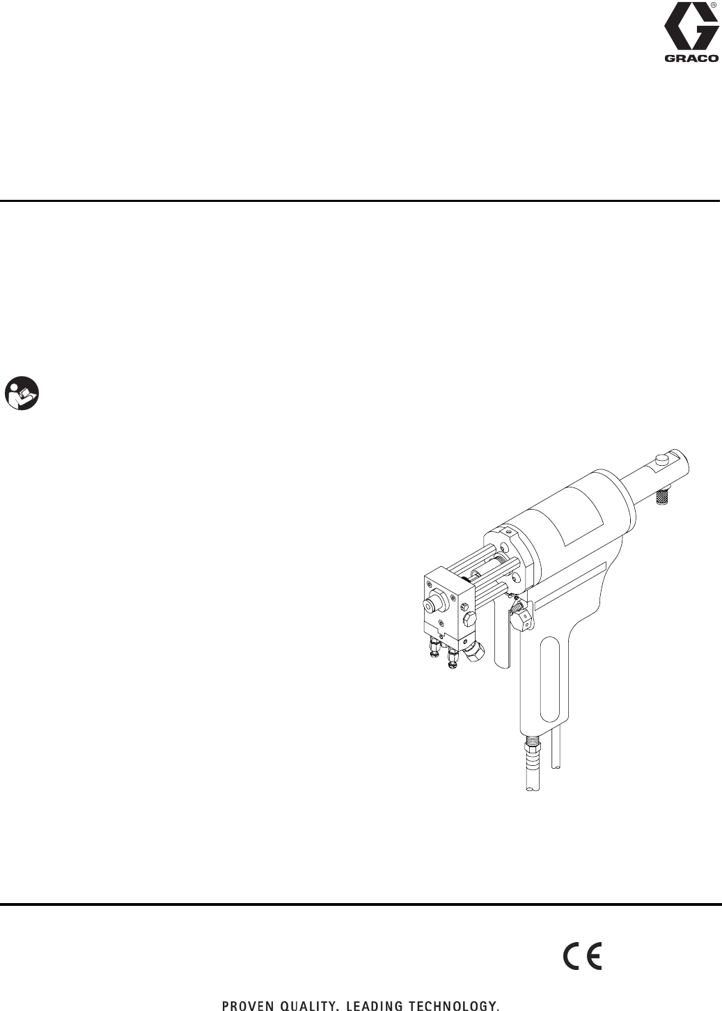
312888D
Operation - Parts
AR Pour Gun
For use with non-flammable polyurethane foams.
Not for use in explosive atmospheres.
Part No. 255828
2000 psi (13.8 MPa, 138 bar) Maximum Working Pressure
Important Safety Instructions
Read all warnings and instructions in this manual.
Save these instructions.
2312888D
Contents
Warnings . . . . . . . . . . . . . . . . . . . . . . . . . . . . . . . . . 3
Isocyanate Hazard . . . . . . . . . . . . . . . . . . . . . . . . . 5
Material Self-ignition . . . . . . . . . . . . . . . . . . . . . . . 5
Moisture Sensitivity of Isocyanates . . . . . . . . . . . . 5
Keep Components A and B Separate . . . . . . . . . . 5
Foam Resins with 245 fa Blowing Agents . . . . . . . 5
Changing Materials . . . . . . . . . . . . . . . . . . . . . . . . . 5
Components . . . . . . . . . . . . . . . . . . . . . . . . . . . . . . 6
Operation Basics . . . . . . . . . . . . . . . . . . . . . . . . . . . 7
Grounding . . . . . . . . . . . . . . . . . . . . . . . . . . . . . . 7
Safety Stop . . . . . . . . . . . . . . . . . . . . . . . . . . . . . 7
Air Hose Connection . . . . . . . . . . . . . . . . . . . . . . 8
Coupling Block . . . . . . . . . . . . . . . . . . . . . . . . . . 8
Initial Set Up . . . . . . . . . . . . . . . . . . . . . . . . . . . . . . 10
Daily Start-Up . . . . . . . . . . . . . . . . . . . . . . . . . . . . . 11
Daily Shutdown . . . . . . . . . . . . . . . . . . . . . . . . . . . 11
Pressure Relief Procedure . . . . . . . . . . . . . . . . . . 12
Maintenance . . . . . . . . . . . . . . . . . . . . . . . . . . . . . . 13
Gun Service Kits . . . . . . . . . . . . . . . . . . . . . . . . 13
Daily Cleaning Procedure,
with Gun Service Kit . . . . . . . . . . . . . . . . . 13
Daily Cleaning Procedure,
without Gun Service Kit . . . . . . . . . . . . . . . 14
Flush Gun . . . . . . . . . . . . . . . . . . . . . . . . . . . . . 14
Trigger Gun While Disconnected . . . . . . . . . . . 14
Troubleshooting . . . . . . . . . . . . . . . . . . . . . . . . . . . 15
Repair . . . . . . . . . . . . . . . . . . . . . . . . . . . . . . . . . . . 16
Pattern Control Tip . . . . . . . . . . . . . . . . . . . . . . 16
Screen Screw and Port Closure Plugs . . . . . . . 16
Valving Rod and Resilient Sleeve . . . . . . . . . . . 17
Coupling Block and Check Valves . . . . . . . . . . . 18
Impingers . . . . . . . . . . . . . . . . . . . . . . . . . . . . . 19
Gun Block . . . . . . . . . . . . . . . . . . . . . . . . . . . . . 20
Pressure Check Valving Rod Resilient Sleeve . 21
Parts . . . . . . . . . . . . . . . . . . . . . . . . . . . . . . . . . . . . 23
AR Pour Gun 255828 . . . . . . . . . . . . . . . . . . . . 23
AR-D Conversion Kit 24A023 . . . . . . . . . . . . . . 29
Electrical Diagram . . . . . . . . . . . . . . . . . . . . . . . . 30
Technical Data . . . . . . . . . . . . . . . . . . . . . . . . . . . 31
Performance Charts . . . . . . . . . . . . . . . . . . . . . . . 31
Graco Standard Warranty . . . . . . . . . . . . . . . . . . . 32
Graco Information . . . . . . . . . . . . . . . . . . . . . . . . . 32
Warnings
312888D 3
Warnings
The following warnings are for the setup, use, grounding, maintenance, and repair of this equipment. The exclama-
tion point symbol alerts you to a general warning and the hazard symbol refers to procedure-specific risk. Refer back
to these warnings. Additional, product-specific warnings may be found throughout the body of this manual where
applicable.
WARNING
TOXIC FLUID OR FUMES HAZARD
Toxic fluids or fumes can cause serious injury or death if splashed in the eyes or on skin, inhaled, or
swallowed.
•
Read MSDS’s to know the specific hazards of the fluids you are using.
•
Store hazardous fluid in approved containers, and dispose of it according to applicable guidelines.
•
Always wear impervious gloves when spraying or cleaning equipment.
PERSONAL PROTECTIVE EQUIPMENT
You must wear appropriate protective equipment when operating, servicing, or when in the operating
area of the equipment to help protect you from serious injury, including eye injury, inhalation of toxic
fumes, burns, and hearing loss. This equipment includes but is not limited to:
•
Protective eyewear
•
Clothing and respirator as recommended by the fluid and solvent manufacturer
•
Gloves
•
Hearing protection
SKIN INJECTION HAZARD
High-pressure fluid from dispense valve, hose leaks, or ruptured components will pierce skin. This may
look like just a cut, but it is a serious injury that can result in amputation. Get immediate surgical
treatment.
•
Do not point dispense valve at anyone or at any part of the body.
•
Do not put your hand over the end of the dispense nozzle.
•
Do not stop or deflect leaks with your hand, body, glove, or rag.
•
Follow Pressure Relief Procedure in this manual, when you stop spraying and before cleaning,
checking, or servicing equipment.
•
Tighten all fluid connections before operating the equipment.
•
Check hoses tubes and couplings daily. Replace worn or damaged parts immediately.
Warnings
4312888D
FIRE AND EXPLOSION HAZARD
Flammable fumes, such as solvent and paint fumes, in work area can ignite or explode. To help prevent
fire and explosion:
•
Use and clean equipment only in well ventilated area.
•
Eliminate all ignition sources; such as pilot lights, cigarettes, portable electric lamps, and plastic drop
cloths (potential static arc).
•
Keep work area free of debris, including solvent, rags and gasoline.
•
Do not plug or unplug power cords or turn lights on or off when flammable fumes are present.
•
Ground equipment, personnel, object being sprayed, and conductive objects in work area. See
Grounding instructions.
•
Use only Graco grounded hoses.
•
Check gun resistance daily.
•
If there is static sparking or you feel a shock, stop operation immediately. Do not use equipment
until you identify and correct the problem.
•
Do not flush with gun electrostatics on. Do not turn on electrostatics until all solvent is removed from
system.
•
Keep a working fire extinguisher in the work area.
EQUIPMENT MISUSE HAZARD
Misuse can cause death or serious injury.
•
Do not operate the unit when fatigued or under the influence of drugs or alcohol.
•
Do not exceed the maximum working pressure or temperature rating of the lowest rated
system component. See Technical Data in all equipment manuals.
•
Use fluids and solvents that are compatible with equipment wetted parts. See Technical
Data in all equipment manuals. Read fluid and solvent manufacturer’s warnings. For com-
plete information about your material, request MSDS forms from distributor or retailer.
•
Check equipment daily. Repair or replace worn or damaged parts immediately with genuine
manufacturer’s replacement parts only.
•
Do not alter or modify equipment.
•
Use equipment only for its intended purpose. Call your distributor for information.
•
Route hoses and cables away from traffic areas, sharp edges, moving parts, and hot sur-
faces.
•
Do not kink or over bend hoses or use hoses to pull equipment.
•
Keep children and animals away from work area.
•
Comply with all applicable safety regulations.
WARNING
Isocyanate Hazard
312888D 5
Isocyanate Hazard
Material Self-ignition
Moisture Sensitivity of
Isocyanates
Isocyanates (ISO) are catalysts used in two component
foam and polyurea coatings. ISO will react with moisture
(such as humidity) to form small, hard, abrasive crystals,
which become suspended in the fluid. Eventually a film
will form on the surface and the ISO will begin to gel,
increasing in viscosity. If used, this partially cured ISO
will reduce performance and the life of all wetted parts.
To prevent exposing ISO to moisture:
•
Always use a sealed container with a desiccant
dryer in the vent, or a nitrogen atmosphere. Never
store ISO in an open container.
•
Keep the ISO lube pump reservoir (if installed) filled
with Graco Throat Seal Liquid (TSL), Part 206995.
The lubricant creates a barrier between the ISO and
the atmosphere.
•
Use moisture-proof hoses specifically designed for
ISO, such as those supplied with your system.
•
Never use reclaimed solvents, which may contain
moisture. Always keep solvent containers closed
when not in use.
•
Never use solvent on one side if it has been contam-
inated from the other side.
•
Always lubricate threaded parts with ISO pump oil
or grease when reassembling.
Keep Components A and
B Separate
Foam Resins with 245 fa
Blowing Agents
New foam blowing agents will froth at temperatures
above 90°F (33°C) when not under pressure, especially
if agitated. To reduce frothing, minimize preheating in a
circulation system.
Changing Materials
•
When changing materials, flush the equipment mul-
tiple times to ensure it is thoroughly clean.
•
Always clean the fluid inlet strainers after flushing.
•
Check with your material manufacturer for chemical
compatibility.
•
Most materials use ISO on the A side, but some use
ISO on the B side.
•
Epoxies often have amines on the B (hardener)
side. Polyureas often have amines on the B (resin)
side.
Spraying materials containing isocyanates creates
potentially harmful mists, vapors, and atomized par-
ticulates.
Read material manufacturer’s warnings and material
MSDS to know specific hazards and precautions
related to isocyanates.
Prevent inhalation of isocyanate mists, vapors, and
atomized particulates by providing sufficient ventila-
tion in the work area. If sufficient ventilation is not
available, a supplied-air respirator is required for
everyone in the work area.
To prevent contact with isocyanates, appropriate per-
sonal protective equipment, including chemically
impermeable gloves, boots, aprons, and goggles, is
also required for everyone in the work area.
Some materials may become self-igniting if applied
too thickly. Read material manufacturer’s warnings
and material MSDS.
The amount of film formation and rate of crystalli-
zation varies depending on the blend of ISO, the
humidity, and the temperature.
CAUTION
To prevent cross-contamination of the equipment’s
wetted parts, never interchange component A (isocy-
anate) and component B (resin) parts.
Components
6312888D
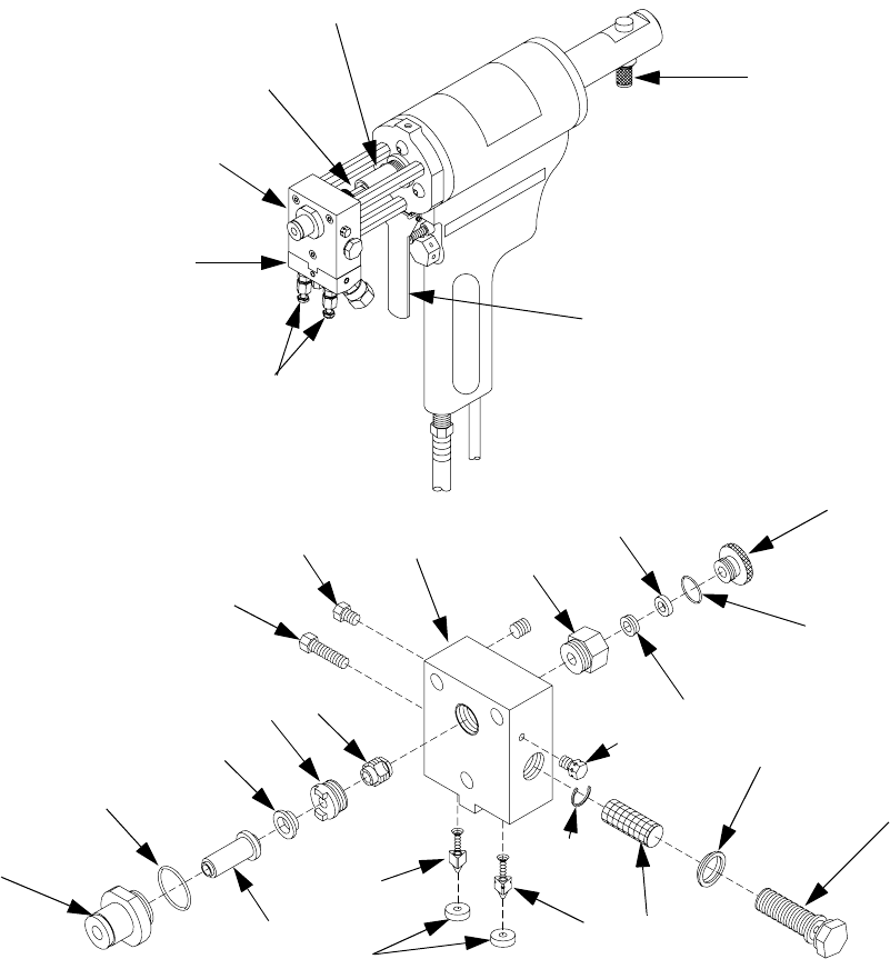
Components
Key:
A Manual Valves
B Gun Block
C Coupling Block
D Trigger
E Valving Rod
F Piston Rod
G Safety Stop
H Pattern Control Tip
J Front Packing
KO-ring
L Front Impinger
M Throat
N Rear Impinger
P Screen Screw Mounting Screw
Q R-Port Closure Screw
R Gun Block
S Resin Seal Retainer
TSpacer
U Resin Seal Screw
VO-ring
WResin Packing
X A-Port Closure Screw
Y Gun Block Screen
Z Gun Block Screen Screw
AA Screen Screw Seal
AB Snap Ring
AC A-Check Valve
AD Coupling Block Gaskets
AE R-Check Valve
Overall View
Gun Block
A
B
C
D
E
F
G
H
K
J
L
MN
P
QRS
T
U
V
W
X
AB
Z
AA
Y
AC
AD
AE
Operation Basics
312888D 7
Operation Basics
Grounding
Check your local electrical code and your proportioner
manual for detailed grounding instructions.
Ground the spray gun through connection to a
Graco-approved grounded fluid supply hose.
Safety Stop
The gun has a two-position safety stop. The SERVICE
(CLOSED) position permits both material inlet ports to
remain closed when gun is triggered.
Engage Safety Stop
To engage safety stop, push in and turn clockwise to
CLOSED (rear detent) position, then release.
Disengage Safety Stop
To disengage safety stop, push in and turn counterclock-
wise to place in OPEN (forward detent) position, then
release.
To prevent accidental gun operation, always discon-
nect air supply before servicing gun or anytime gun is
not in use. Safety Stop
Operation Basics
8312888D
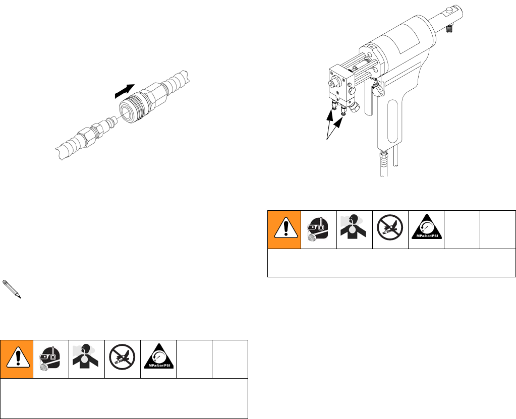
Air Hose Connection
Connect Air Hoses
Pull back sleeve of female fitting, insert male fitting and
slide sleeve forward to secure connection.
Disconnect Air Hoses
Pull back sleeve of female fitting and pull out male fitting.
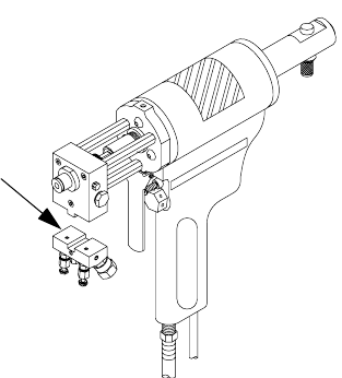
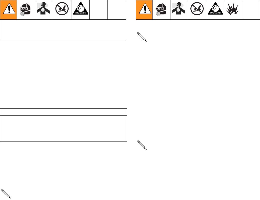
Coupling Block
Chemical hoses are joined to gun block by coupling
block to ease installation and removal of gun.
Manual Valves
1. Open manual valves using 5/16 in. nut driver; turn
manual valves counterclockwise approximately
three full turns. Do not open until it bottoms out.
2. Close manual valves by turning fully clockwise.
Removal and Installation
Remove Coupling Block
1. Set safety stop to SERVICE (CLOSED).
2. Disconnect air hose.
3. Close both manual valves.
4. Remove coupling block mounting screw.
5. Separate coupling block from gun.
6. Wipe mating surfaces of gun block and coupling
block to remove residual chemical.
Triggering gun with manual valves closed may
cause crossover if gun ports contain residual chem-
ical.
To prevent release of pressurized chemicals, never
open manual valves unless coupling block is secured
to gun or exit port is directed into flush pail.
Pull Sleeve
To prevent release of pressurized chemicals, close
both manual valves before removing coupling block.
Manual Valves
Operation Basics
312888D 9
7. Cover exposed openings with grease.
Install Coupling Block
Replace nicked, damaged, or worn coupling block gas-
kets.
1. With gaskets in place, fit coupling block to gun
block.
2. Insert coupling block mounting screw and use
5/16 in. nut driver to tighten to gun block.
Coupling
Block

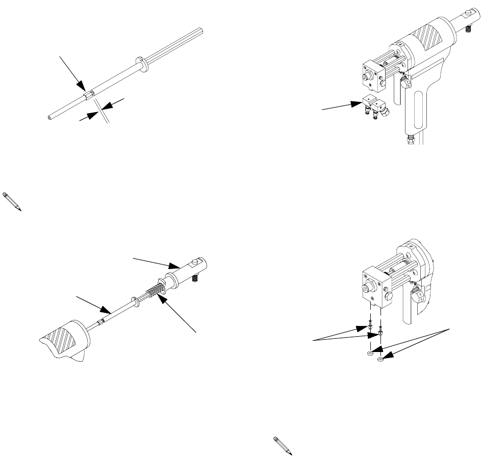
Initial Set Up
10 312888D
Initial Set Up
1. Remove coupling block from gun.
2. Check valving rod clearance in closed position. Rod
should extend approximately 1/32 in. (1 mm)
beyond tip of mixing chamber.
3. Adjust valving rod travel to initial setting. See Valv-
ing Rod and Resilient Sleeve, page 17.
4. Connect air supply hose to gun.
5. Connect A-isocyanate hose (red-taped) to notched
fitting on coupling block. Then connect R-resin hose
(blue-taped) to fitting without notches on coupling
block.
6. Close both manual valves.
7. Pressurize the A and R chemical hoses and check
for leaks. (See Proportioning Unit manual.)
8. Bleed air from chemical hoses:
a. Hold coupling block with exit ports pointed into
disposable container.
b. Open each manual valve to allow trapped air to
escape. Bleed each side until chemical is free of
air.
c. Close both manual valves.
9. Use clean cloth soaked in gun cleaner to wipe clean
coupling block and its mating surfaces.
10. Install coupling block to gun block.
11. Proceed with Daily Start-up procedure or Shutdown
procedure as required.
CAUTION
To avoid accumulation of dirt and other contaminants,
do not apply grease to mating surfaces of coupling
block.
Daily Start-Up
312888D 11
Daily Start-Up
1. Ensure gun is mounted onto gun block.
2. Connect air supply to gun; see Air Hose Connec-
tion, page 8.
3. Connect electrical harness to gun.
4. Trigger gun multiple times to ensure valving rod
moves through its full travel quickly and freely.
5. Open both manual valves; see Manual Valves,
page 8.
6. Test spray on disposable surface and adjust spray
pattern as needed.
Daily Shutdown
1. Set safety stop to OPEN.
2. Close both manual valves.
3. Disconnect air supply from gun.
4. Shutdown proportioning unit as required. See Pro-
portioner manual.
5. Clean as required.
Ensure gun is attached to coupling block and air hose,
and the proportioning unit is at desired temperature
and pressure.
CAUTION
Sluggish valving rod action may result in valving rod
sticking in open position when fluid pressure is
applied. Always have a 5/16 in. nut driver available to
quickly close manual valves on coupling block.
Do not exceed 2000 psi (13.8 MPa, 138 bar) maxi-
mum fluid working pressure even in static de-trig-
gered conditions, or check valve damage may
result.
Follow daily shutdown when gun is out of service
for any length of time. Daily disassembly of gun for
cleaning is not recommended if it has been operat-
ing properly. However, if you remove the gun from
the coupling block, flush and clean thoroughly.
Do not disassemble gun daily for cleaning if it is
operating properly. However, if gun is removed from
coupling block, it must be flushed and cleaned thor-
oughly.
Pressure Relief Procedure
12 312888D
Pressure Relief Procedure
1. Close both manual valves.
2. Set safety stop to OPEN.
3. Trigger gun onto cardboard or into waste container
to relieve pressure.
4. Release gun trigger, set safety stop to SERVICE
(CLOSED), and close manual valves.
Relieve pressure before cleaning or repairing gun.
If fluid in hose and proportioner is still under pressure,
follow Pressure Relief Procedure in your Proportioner
manual.
To relieve pressure in hose after gun is removed, place
fluid manifold over containers, facing away from you.
Very carefully open fluid valves. Under high pressure,
fluid will spray sideways from fluid ports.
Manual Valves
Maintenance
312888D 13
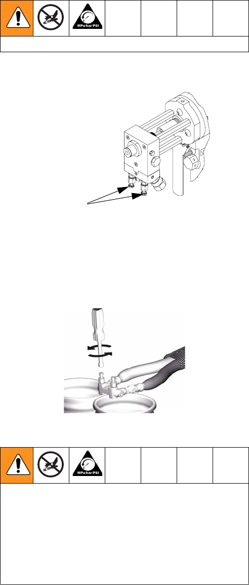
Maintenance
Gun Service Kits
Use either the 1-Quart Gun Service Kit (296980) or
3-Gallon Gun Service Kit (296981) to perform daily
flushing of spray gun without disassembly.
For more information about the 1-Quart Gun Service Kit,
see Manual 311340.
For more information about the 3-Gallon Gun Service
Kit, see Manual 311340.
Daily Cleaning Procedure,
with Gun Service Kit
1. Set safety stop to SERVICE (CLOSED).
2. Close both manual valves.
3. Remove gun from coupling block.
4. Disconnect air and electric.
5. Attach service block of gun service kit to gun, and
then tighten using 5/16 in. nut driver.
6. Pressurize Service Kit container up to 100 psi. Do
not exceed 100 psi (0.7 MPa, 7 bar).
7. Open one manual valve on service block.
8. Connect air to gun. Set safety stop to OPEN.
9. Hold gun against grounded waste container.
10. Trigger gun and 1-Quart Gun Service Kit. Spray into
waste container until there is a fine, unobstructed
mist of gun cleaner.
11. Release trigger and close manual valve on service
block.
12. Repeat steps 7-11 for other side of gun.
13. Remove service block of gun service kit from spray
gun.
14. Set safety to SERVICE (CLOSED).
15. Disconnect air supply.
16. Clean removed component parts.
1-Quart Kit
3-Gallon Kit
To avoid static sparking that may result in fire or explo-
sion, ensure all equipment in cleaning procedure is
grounded. Do not clean on or near foamed or coated
surfaces or any other flammable surfaces or objects.
Do not use metal cleaning devices to clean plastic
components.
Maintenance
14 312888D
Daily Cleaning Procedure,
without Gun Service Kit
If the Gun Service Kit is not available, the iso side com-
ponents must be cleaned daily.
1. Place safety stop in SERVICE (CLOSED) position.
2. Remove pattern control tip.
3. Remove front impinger, packing, and o-ring from
pattern control tip.
4. Using pattern control tip/impinger cleanout tool
(607), clean the inside bore of the pattern control tip
by inserting and spinning.
5. Using cleanout spade (609), clean the front
impinger by sliding through slots. Clean inside bore
of the impinger as necessary.
6. Inspect packing for built-up iso and deformities and
replace as necessary.
7. Inspect o-ring for flat areas and replace as neces-
sary.
8. Remove screen screw then remove screen from
screen screw. Inspect gasket and replace as neces-
sary.
9. Clean screen screw and screen with solvent. If iso
build-up exists on screen screw, clean with brass
wire brush as necessary.
10. Clean gun block with solvent.
11. Remove iso check valve gasket using gasket
removal tool (611).
12. Using check valve removal tool (612), remove iso
check valve.
13. Clean all parts with solvent then blow dry with com-
pressed air and reassemble.
Flush Gun
1. Set safety stop to SERVICE (CLOSED).
2. Close both manual valves.
3. Loosen screen screw and then remove by hand.
4. Use flush can to thoroughly flush screen screw and
screen screw cavity.
5. Service gun by following Troubleshooting proce-
dures, page 15.
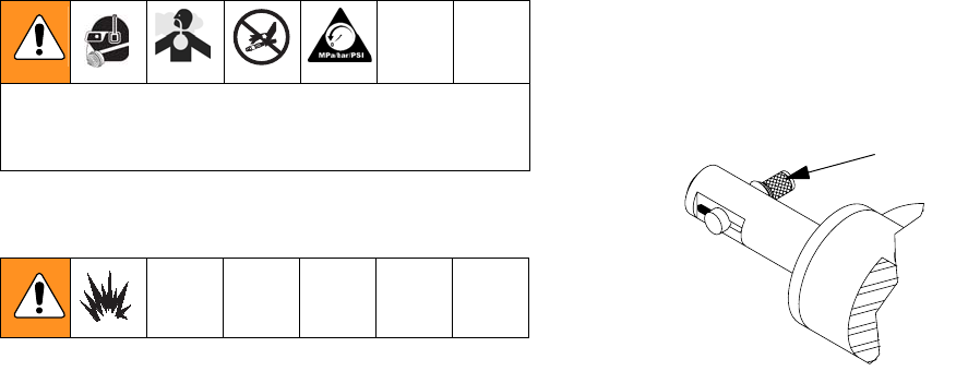
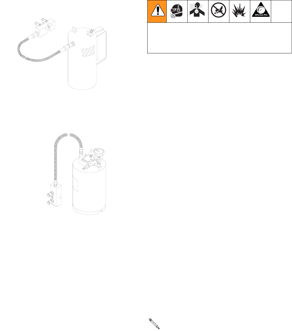
Trigger Gun While Disconnected
During gun maintenance, it may be helpful to trigger the
gun while the electrical harness is disconnected. To do
so, perform the following steps.
1. Connect gun to air supply.
2. Using a small allen key, insert the small end into the
center hole of the exhaust valve cap (217) located
behind the trigger.
3. Pull trigger to depress allen key into muffler and
activate the valving mechanism. The gun should
trigger and the valving rod should pull back.
See AR Gun Tool Kit 253728 on page 28.
To avoid static sparking that may result in fire or explo-
sion, ensure all equipment in flushing procedure is
grounded. Do not flush on or near foamed or coated
surfaces.
217

Troubleshooting
312888D 15
Troubleshooting
Problem Cause Solution
Interruption of flow of one material Running out of material Supply more material to proportioner
Change of color in mixed product
Materials in proportioner are too vis-
cous
Check with material supplier for rec-
ommended temperature range that
should be maintained to control vis-
cosity.
Only one component coming out of
gun
Filter screens are clogged Flush gun. See Flush Gun, page 14.
Poor spray pattern
Materials in proportioner are too vis-
cous
Check with material supplier for rec-
ommended temperature range that
should be maintained to control vis-
cosity.
Impinger slots are clogged See Impingers, page 19, for service
instructions.
Minor weepage around throat in gun
block
Valving rod is worn Perform Pressure Check Valving
Rod Resilient Sleeve procedure;
see page 21.
Valving rod or throat is
damaged
Perform Pressure Check Valving
Rod Resilient Sleeve procedure;
see page 21.
Repair
16 312888D
Repair
Tools Required
•
flush can
•
impinger cleanout brush
•
5/16 in. nut driver
•
utility knife
•
pin vise without cleanout spade
•
gun block component hole cleanout brush
•
check valve removal tool
•
throat wrench
•
pattern control tip front impinger packing seal
cleanout tool
•
gasket removal tool
•
wooden stick
•
pry tool/rear impinger wrench
•
pressure flush kit (optional)
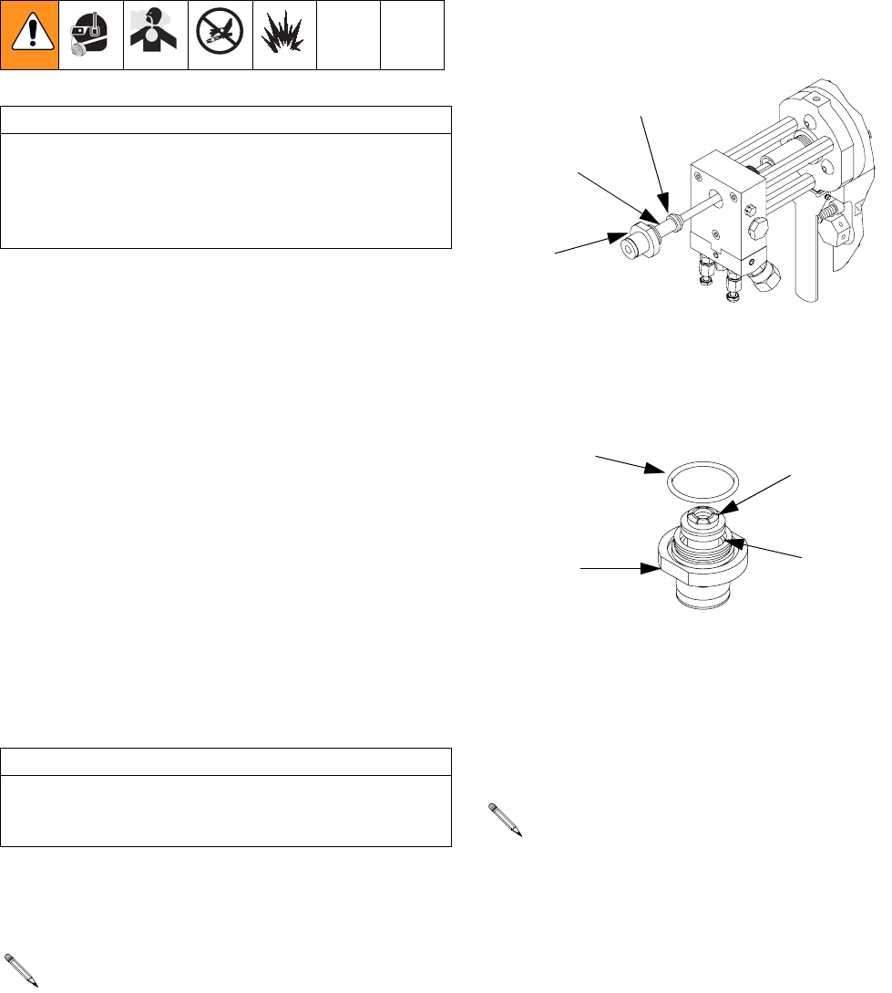
Pattern Control Tip
1. Set safety stop to SERVICE (CLOSED).
2. Loosen pattern control tip with a 10 in. adjustable
wrench. Once loosened, unthread tip by hand.
3. Remove front impinger from front packing. It is not
necessary to remove front packing if no damage to
packing is evident or suspected.
4. Remove pattern control tip o-ring and front packing
from pattern control tip. If packing cannot be
removed by hand, use pliers. However, this will
require replacement of packings.
5. Use pattern control tip cleanout tool to clean inside
walls of tip. Flush tip and clean surrounding external
surface.
6. Set pattern control tip and front impinger and pack-
ing aside.
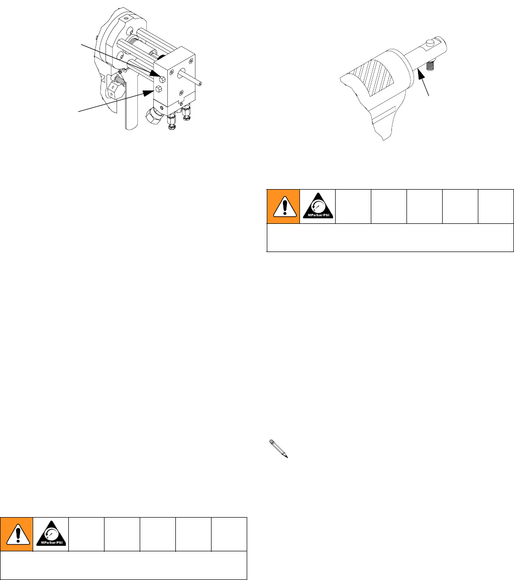
Screen Screw and Port Closure
Plugs
1. Perform Pattern Control Tip steps; see page 16.
2. Use a 5/16 in. nut driver to remove screen screw
mounting screw while holding large hex head of
screen screw with finger or against solid surface.
CAUTION
Shutdown proportioner and allow chemicals to cool
before servicing gun.
Clean A and R components in separate containers to
avoid cross contamination.
CAUTION
Ensure safety stop is set to SERVICE (CLOSED)
while removing pattern control tip. If it is not, the resil-
ient sleeve of the valving rod may be damaged.
If front packing and/or front impinger remain on
valving rod when pattern control tip is removed,
release trigger and carefully slide these parts off
valving rod.
Reassembly instructions are included in
Impingers, page 19.
Front Impinger
Front Packing
Pattern
Control
Tip
O-ring
Front Impinger
Front Packing
Pattern
Control
Tip
Repair
312888D 17
3. Slide screen screw assembly out of gun block. Allow
excess Isocyanate material to drain.
4. Flush assembly and place it in gun cleaner.
5. Remove port closure plugs with nut driver. These
are installed using high-strength sealant, apply heat
to help break free when removing.
6. Clean port closure plugs with gun cleaner and
inspect for damage. Replace if necessary. Apply
sealant (49) to plugs before reinstalling.
7. Remove screen from screen screw. Soak in gun
cleaner or replace if clogged or dirty.
8. Clean screen screw cavity. Clean with clean out
drills and flush with gun cleaner. If more than 20% of
screen is blocked, replace screen.
9. Inspect screen screw seal and closure screw gasket
for damage. Replace if necessary.
10. Reinstall screen screw assembly and tighten mount-
ing screw.
11. Insert port closure plugs.
Valving Rod and Resilient
Sleeve
Disassembly and Cleaning
1. Follow Pressure Relief Procedure, page 12.
2. Remove spring retainer case by grasping handle
firmly and pushing in on retainer case with palm of
hand. Simultaneously rotate case a quarter turn
counterclockwise to remove case from locking col-
lar.
3. Cover open end of air cylinder with hand protected
by a cloth and depress gun trigger.
4. Disconnect airline to gun. Pull back on outer ring of
quick disconnect coupling to disconnect air from
gun.
5. Disconnect electrical harness from gun.
6. Examine resilient sleeve assembly for damage.
Structural damage or wear will show as:
•
scratches or chaffing of outside wall of sleeve;
•
movement or extrusion of sleeve in either
threaded mandrils;
•
reduction in sleeve diameter.
7. If any damage or wear exists, replace both valving
rod resilient sleeve and front packing.
8. Remove valving rod resilient sleeve assembly if it
needs to be replaced.
a. Use a 6 in. adjustable wrench to unthread cou-
pler toward resilient sleeve. If necessary, use a
5/16 in. nut driver to hold valving rod.
b. Once coupler is loose, unthread resilient sleeve
assembly.
Inadvertent actuation of trigger with spring retainer
case removed could cause serious injury.
Port Closure Plug
Screen Screw
Mounting Screw
The following two steps must be accomplished next to
prevent accidental operation of gun.
A uniform depression of equal depth around diame-
ter of sealing point of throat is normal.
Spring Retainer Case
Repair
18 312888D
Reassembly
1. If valving rod resilient sleeve assembly was removed
or is being replaced, use the following steps:
a. Thread coupler onto resilient sleeve assembly
by hand as far as it will go toward sleeve. There
should be approximately 1/16 in. (1.5 mm)
clearance between coupler and valving rod.
b. Use a 6 in. adjustable wrench and a 5/16 in. nut
driver to securely tighten coupler.
2. Align slot on valving rod with pin in cylinder and
push valving rod assembly all the way forward then
rotate 180 degrees.
3. Insert valving rod closure spring into cylinder and
over end of valving rod.
4. Push valving rod retainer case over spring into cylin-
der and rotate clockwise (approximately a quarter
rotation) until retainer case snaps into position.
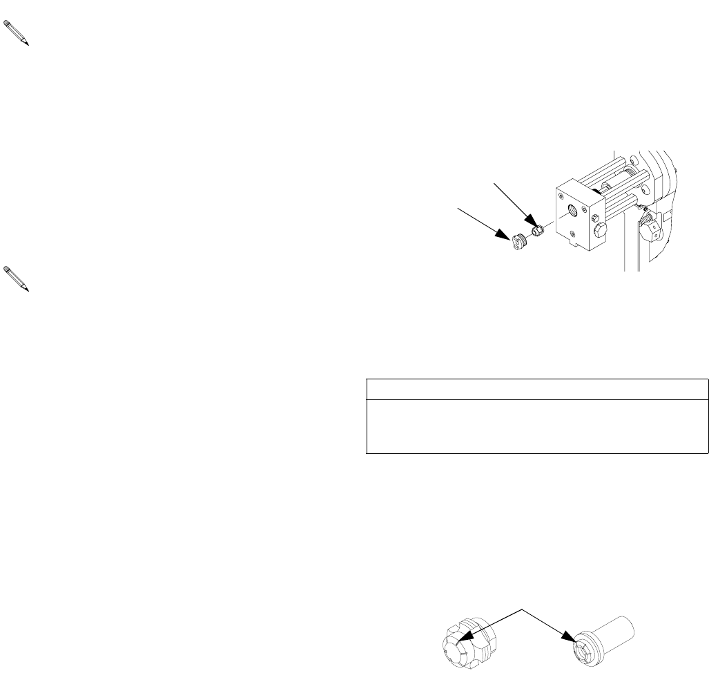
Coupling Block and Check
Valves
Disassembly
1. Follow Pressure Relief Procedure, page 12.
2. Use 5/16 in. nut driver to remove coupling block
mounting screw, and separate gun from coupling
block.
3. Flush both material ports on face of coupling block
to prevent material buildup.
4. Remove check valve gasket. Place end of coupling
block gasket removal tool into notches next to gas-
kets and pry them out.
5. Flush open ports and check valves with gun cleaner.
6. Remove check valves by pressing them inward and
popping them out, or by using the magnet.
There should be some resistance when pushing
valving rod assembly through throat.
Coupler
1/16 in.
Valving Rod Retainer Case
Valving Rod
Closure Spring
Valving Rod Assembly
Iso check valve is notched for identification pur-
poses.
Coupling
Block
Coupling
Block Gaskets
Check
Valves
Repair
312888D 19
7. If material buildup prevents easy removal, use
three-pronged end of check valve removal tool to
grasp check valve and turn free.
8. Place all parts in gun cleaner and flush exposed
ports.
Reassembly
1. Inspect seats on gaskets for nicks. Replace seats if
damaged.
2. Insert check valves (notched valve on left side) and
gaskets into gun block pressing gaskets in place.
3. Place coupling block to gun and use 5/16 in. nut
driver to install coupling block mounting screw.
Impingers
Disassembly and Cleaning
1. Follow Pressure Relief Procedure, page 12.
2. Perform Pattern Control Tip steps; see page 16.
3. Remove rear impinger from throat. Hold throat in
place with throat wrench (604) and use rear
impinger wrench 28576 to loosen impinger from
throat. Continue un-threading by hand.
4. Flush gun block with gun cleaner.
5. Inspect seating surface (area around center hole)
within throat for damage. Use a soft object, such as
a wooden stick or soft brush, to clean surface.
6. Use impinger cleaning brush (608) to clean both
external and internal threads of throat.
7. Use impinger cleaning brush to clean rear and front
impingers. Use cleanout spade to clean each injec-
tion slot of both impingers.
Reassembly
1. Assemble rear impinger into throat. Thread slotted
end of rear impinger into female thread of throat.
Hold throat in place with throat wrench and use rear
impinger wrench to tighten impinger into throat.
Opposite end of check valve removal tool is
designed to clean check valve cavity.
Gaskets are designed for use on either side. Care-
fully check angular seat to ensure sealing point of
check valve.
CAUTION
Never use a sharp or hard metal object for cleaning
impingers or throat. Seating surface of throat is highly
polished to ensure sealing of resilient sleeve.
Throat
Rear Impinger
Rear Impinger Front Impinger
Injection Slots
Repair
20 312888D
2. Thread throat assembly by hand into gun block. Use
throat wrench to tighten.
3. Assemble front impinger and pattern control tip.
Insert front packing into pattern control tip. Place
front impinger over end of front packing. Place pat-
tern control tip o-ring into groove on pattern control
tip.
4. Engage safety stop, see Safety Stop on page 7.
Press and hold trigger then hand-tighten pattern
control tip into gun block.
5. Release trigger to align components then press and
hold trigger. Use 10 in. adjustable wrench to tighten
pattern control tip about 1/8-turn. Release trigger.
Repeat until the pattern control tip is snug on the
gun block.
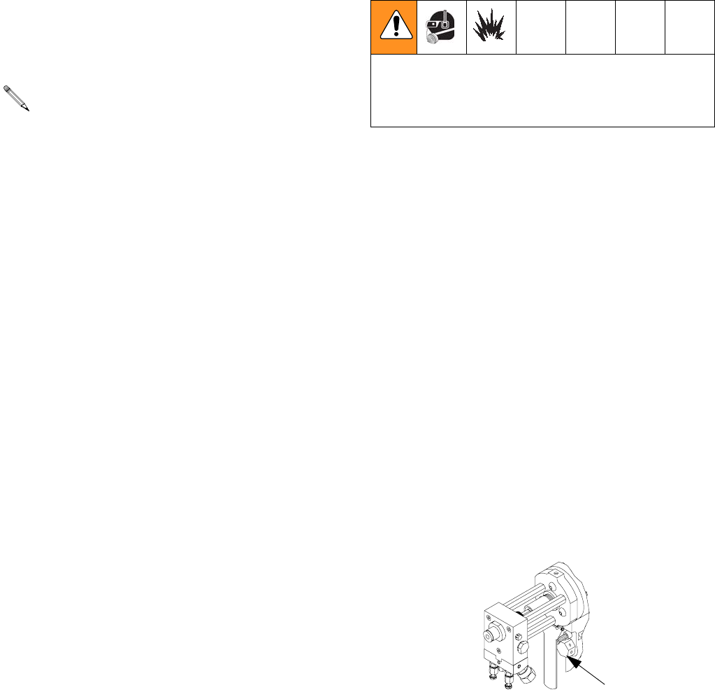
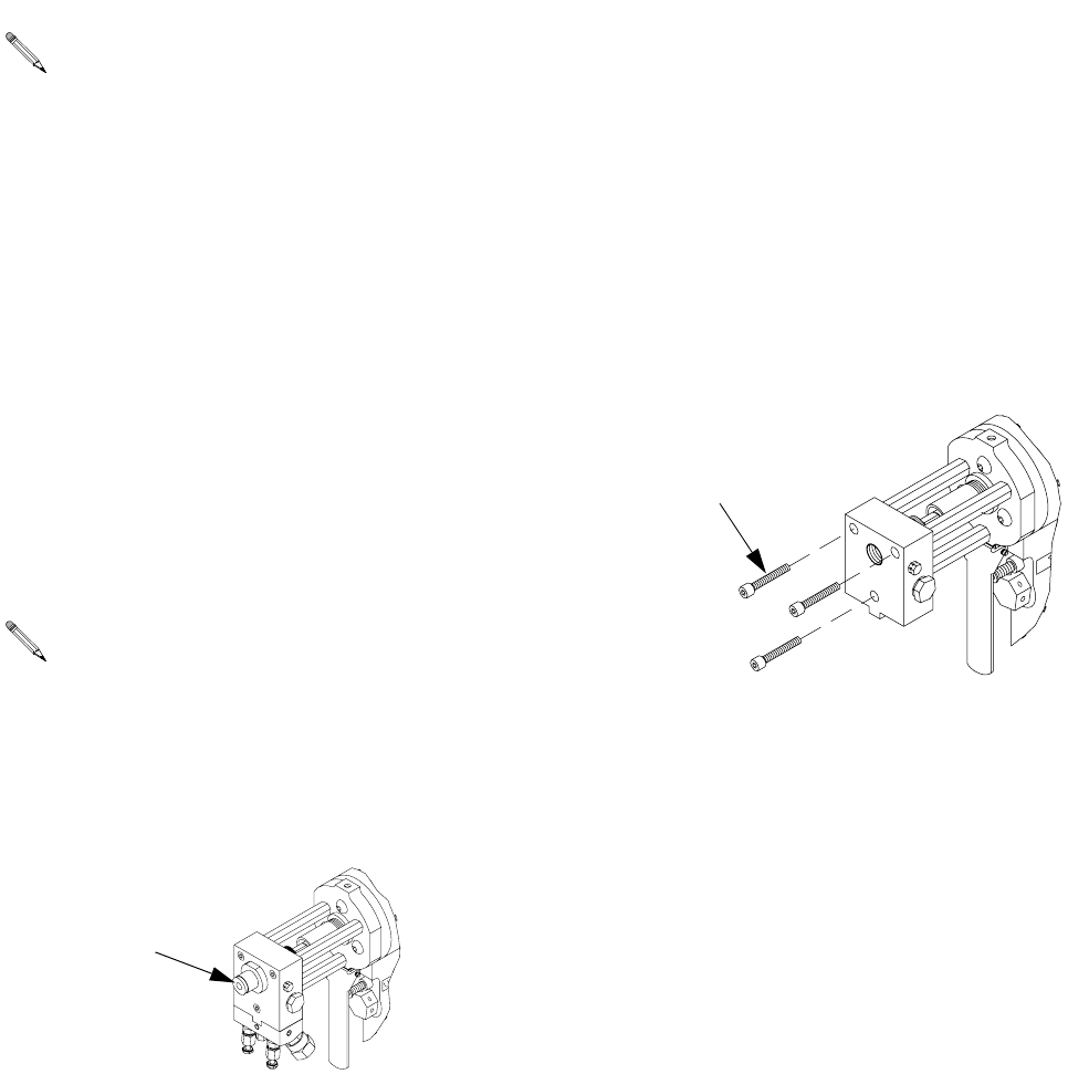
Gun Block
In severe cases of material buildup, it may be necessary
to remove the gun block and soak it in gun cleaner.
1. Follow Pressure Relief Procedure, page 12.
2. Remove the pattern control tip and front impinger;
see Pattern Control Tip, page 16.
3. Remove coupling block and check valves; see Cou-
pling Block and Check Valves, page 18.
4. Remove rear impinger and throat; Impingers, page
19.
5. Remove gun block mounting screws.
6. Remove resin (rear) seal screw and resin seal
o-rings.
Front impinger should contact throat surface about
1/2 to 3/4 turns from actual seating of throat to gun
block surface. This compression creates the inter-
nal seal within front portion of chamber.
If after finishing step 5 the valving rod is not pro-
truding at least 1/64 in. from the end of the pattern
control tip, the pattern control tip will need to be
removed then steps 4 and 5 repeated. The pattern
control tip will need to be tightened in 1/16- or
1/32-turn increments.
Pattern
Control Tip
Mounting Screws
Repair
312888D 21
7. Soak gun block in gun cleaner.
8. Reassemble resin (rear) seal screw and resin seal
o-rings into gun block.
9. Reinstall gun block using gun block mounting
screws.
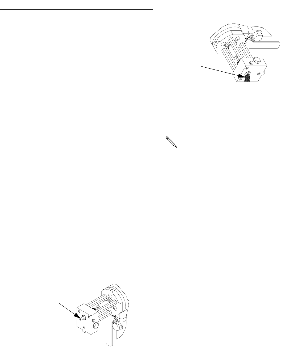
Pressure Check Valving Rod
Resilient Sleeve
Perform this test to check seal created by interference fit
between resilient sleeve and opening in throat.
1. Follow Pressure Relief Procedure, page 12.
2. Remove the pattern control tip and front impinger;
see Pattern Control Tip, page 16.
3. Remove coupling block and check valves; see Cou-
pling Block and Check Valves, page 18.
4. Remove rear impinger and throat; Impingers, page
19.
5. Turn on proportioner, and with only the resin manual
valve open, determine if there are resin leaks at
front (Iso) surface of throat.
6. Set safety stop to SERVICE (CLOSED), and then
pull trigger to determine if weepage occurs in this
position.
7. If weepage is observed in either step, replace valv-
ing rod and/or throat. See Valving Rod and Resil-
ient Sleeve, page 17, to replace valving rod. See
Impingers, page 19, to replace throat.
8. Close resin manual valve.
CAUTION
Do not allow gun block or component parts to soak in
gun cleaner for extended periods of time, such as
overnight, as certain solvents may cause corrosion or
pitting.
Do not soak gun block o-rings in gun cleaner. To clean
o-rings, dip in gun cleaner and immediately wipe dry.
Should be protruding
If throat is not properly seated in gun block, mate-
rial leakage will occur around outer area of throat. If
this occurs, insert throat wrench over resilient
sleeve and tighten throat.
Weepage

Repair
22 312888D
Parts
312888D 23
Parts
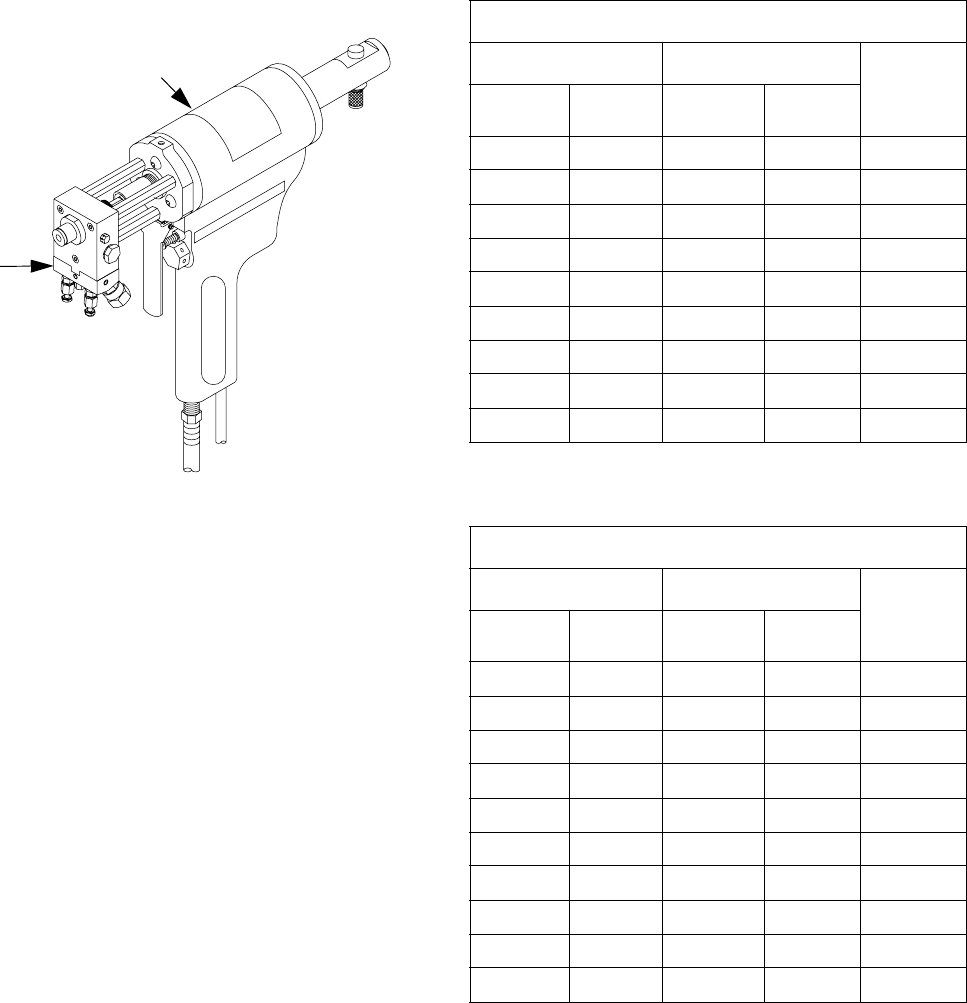
AR Pour Gun 255828 Impinger Options
Table 1: Impinger Options - C Size
Table 2: Impinger Options - D Size
Ref Part Description Qty
BA 255827 GUN, auto AR-C 1
BB 253728 KIT, AR gun tool (not shown) 1
BC 285771 BLOCK, AR coupling 1
BC
BA
Impinger (C Size)
Front Rear Orifice
Area
FactorPart Style Part Style
299974 23-B-1 299990 23-B-1 900
299975 33-B-1 None 33-B-1 1200
299976 33-C-1 299991 33-C-1 1800
299977 34-C-1 299992 34-C-1 2400
299980 46-B-1 299995 46-B-1 3000
299978 36-C-1 299993 36-C-1 3600
None 46-C-1 299996 46-C-1 4500
299982 48-C-1 299997 48-C-1 6000
299983 58-C-1 299999 58-C-1 7200
Impinger (D Size)
Front Rear Orifice
Area
FactorPart Style Part Style
299979 33-C-1 None 33-C-1 1800
None 36-C-1 299994 36-C-1 3600
None 48-C-1 299998 48-C-1 6000
None 58-C-1 261789 58-C-1 7200
299984 59-D-1 None 59-D-1 10800
299985 66-D-1 285750 66-D-1 8400
None 78-D-1 285751 78-D-1 12800
261790 79-D-1 None 79-D-1 14400
299987 90-D-1 285752 90-D-1 18000
299988 94-D-1 None 94-D-1 25200
Parts
24 312888D
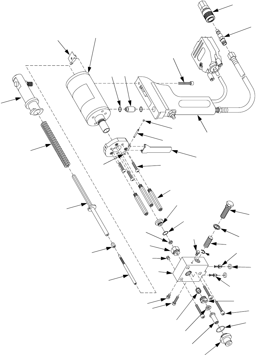
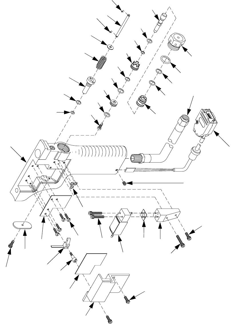
Auto AR-C Gun 255827
1†
6
12
3†
2†
4†
17
14
5
36◆
33◆
37
7
19
29
32
41
31
15
8
13
22
23
40 934 35
18
24
25
21
27
39
19
26
28
11
10
20
44
43
38
Parts
312888D 25
†
Parts included in Kit 296624, available separately.
◆
Parts included in Kit 298357, available separately.
Ref Part Description Qty
1† 296621 SEAL, screw, screen 1
2† 296622 SCREEN, block, gun 1
3† 295595 RING, retaining 1
4† 295175 SCREW, screen, gun block 1
5 296128 GASKET, block, gasket 2
6 295623 VALVE, check, A 1
7 295624 VALVE, check, R 1
8 297307 SCREW, mounting, 1 in. 1
9 295693 PLUG, pipe 1
10 295596 PLUG, coupler 1
11 208536 COUPLER, line, air 1
12 297308 SCREW, closure, A-port 1
13 296129 SCREW, closure, R-port 1
14 299923 BLOCK, gun spacer w/stud 3
15 297150 SCREW, cap, socket head 3
16 299925 HANDLE, gun mounting plate 1
17 299951 TRIGGER, lever 1
18 298354 PIN, mounting 1
19 299475 RETAINER 1
20 299960 CYLINDER, air assy 1
21 299962 ROD, valving 1
22 297312 COLLAR, lock 1
23 296136 SLEEVE 1
24 299966 RETAINER, spring case assy 1
25 297313 SPRING, die, heavy duty 1
26 299969 COUPLING, connecting 1
27 297314 O-RING, fluoroelastomer 2
28 299970 STOP, notched 1
29 111603 PACKING, o-ring 1
31 296137 PACKING, front 1
32 296138 PACKING, throat 1
33 103648 PACKING, o-ring 1
34 298355 SEAL, retainer, 250 1
35 296140 PACKING, R 1
36 298356 SEAL, screw, 250 1
37 298117 SCREW, 1/4-28 x 1 bhcs-nyloc 2
38 299908 SCREW, 1/4-28 x 1 1/4
shcs-nyloc
1
39 256213 HANDLE, auto ar gun 1
40 285795 BLOCK, gun assy 1
41 299973 TIP, 250 pattern control, also
shown on page 24
1
42 IMPINGER, front; see
Impinger Options on page 23
for part numbers
1
43 IMPINGER, rear; see
Impinger Options on page 23
for part numbers
1
49 102969 ADHESIVE, anaerobic 1
Ref Part Description Qty
Parts
26 312888D
Gun Handle Assembly 256213
206
230
213
232
212
211
210
209
208
205
207
205
202
205
216
210
215
214
234
217
233
231
219
228
235
203
201
201
229
224
220
204
221
203
203
222
218
227
226
223
225
230
Parts
312888D 27
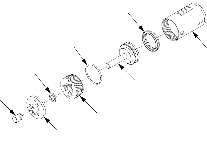
Air Cylinder Assembly 299960
Ref Part Description Qty
201 298116 SCREW, 4-40 x 3/4 shcs 3
202 108195 PACKING, o-ring 1
203 C19950 SCREW, cap, sch 4
204 296066 O-RING, piston, pump 3
205 106555 PACKING, o-ring 3
206 106560 PACKING, o ring 1
207 C20988 PACKING, o-ring 1
208 112085 PACKING, o-ring 1
209 299917 SCREW, 5-40 x 3/8
button-hd cap
1
210 295685 O-RING 2
211 299926 TRIGGER, bushing 1
212 299927 SPRING, 1
213 299928 TRIGGER, actuator pin 1
214 299929 SPOOL 1
215 299930 RING, seal 1
216 299931 ROD, piston 1
217 299932 VALVE, exhaust cap 1
218 299933 INSULATOR, circuit board 1
219 256214 WIRE, gun harness assy 1
220 299936 MANIFOLD, air 1
221 299937 SCREW, 2-56 x 7/16 phms 4
222 299938 COVER 1
223 299939 PLATE, rear cover 1
224 299940 GASKET, pilot valve 1
225 15M966 BOARD, assy 1
226 299135 SWITCH, arm lever 1
227 299020 SCREW, shoulder 1
228 102279 SCREW, set, socket 1
229 299948 VALVE, solenoid valve assy 1
230 299475 RETAINER 2
231 299971 HOSE, 1/4 x 2 in. (mxf) air 1
232 285776 WASHER, packing washer 1
233 295439 LINER, valve, spool 1
234 114375 PACKING, o-ring 1
235 HANDLE 1
Ref Part Description Qty
401
405
402
403
406
404
407
403
Ref Part Description Qty
401 299954 COVER, dust 1
402 297309 SEAL, u-cup, fluoroelastomer 1
403 299956 CYLINDER, air 1
404 299957 PISTON, assy 1
405 299959 CYLINDER, flange assy. 1
406 297310 O-RING, fluoroelastomer 1
407 297311 SEAL, u-cup, fluoroelastomer 1
Parts
28 312888D
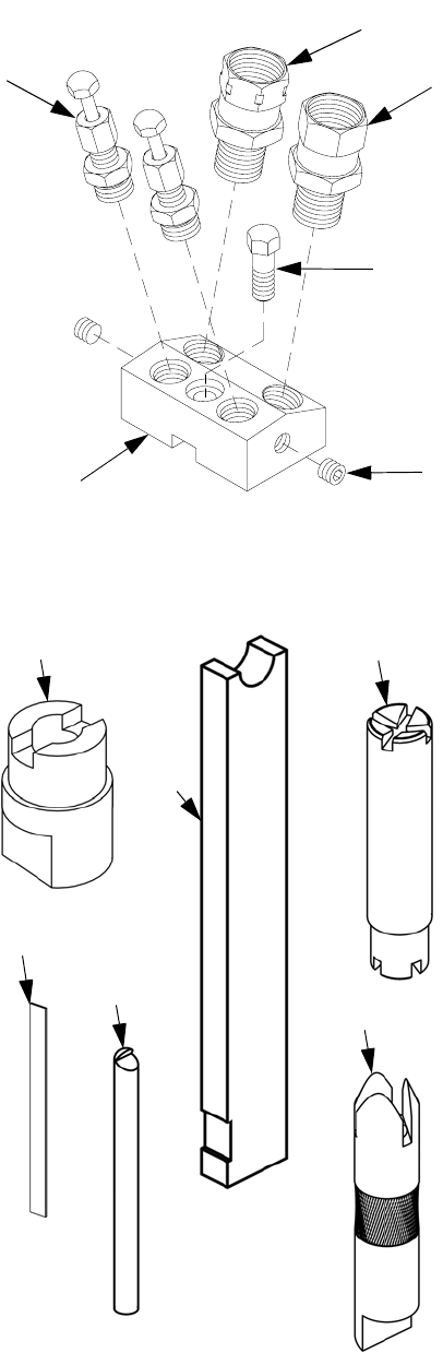
Coupling Block Assembly 285771
AR Gun Tool Kit 253728
501
504 502
503 505
506 Ref Part Description Qty
501 295619 SCREW, mounting 1
502 295693 PLUG, pipe (285771 only) 2
503 VALVE, manual 2
504 BLOCK, coupling 1
505 117506 FITTING, swivel, 1/4 npt x #6
JIC
1
506 117595 FITTING, swivel, 1/4 npt x #5
JIC
1
604 607
611
609
606
612
Ref Part Description Qty
601 117642 TOOL, nut driver 1
602 117661 PIN, vise 1
603 118665 TUBE, grease, 4 oz 1
604 285763 TOOL, throat wrench 1
605 KIT, cleanout drills 1
606 285765 TOOL, 250 rear impinger wrench 1
607 285767 TOOL, 250 pct/imp cleanout 1
608 295898 BRUSH, cleanout, impinger 1
609 295935 KIT, spade, cleanout 1
610 296187 BRUSH, bore, cleanout, gun block 1
611 296191 TOOL, removal, gasket 1
612 297973 TOOL, removal, valve 1

Parts
312888D 29
AR-D Conversion Kit 24A023
See Repair section on page 16 for conversion kit
parts installation.
Ref Part Description Qty
701 299961 CYLINDER, air assy (AR-D) 1
702 297141 SLEEVE, AR-D (375) 1
703 299968 SPRING, die, heavy duty, medium 1
704 285755 SEAL, 375 resin retainer 1
705 285756 SEAL, 375 resin screw 1
706 297143 PACKING 1
707 299989 NOZZLE, 375 throat 1
708 297142 PACKING, front 1
709 299972 TIP, 375 pattern control 1
Electrical Diagram
30 312888D
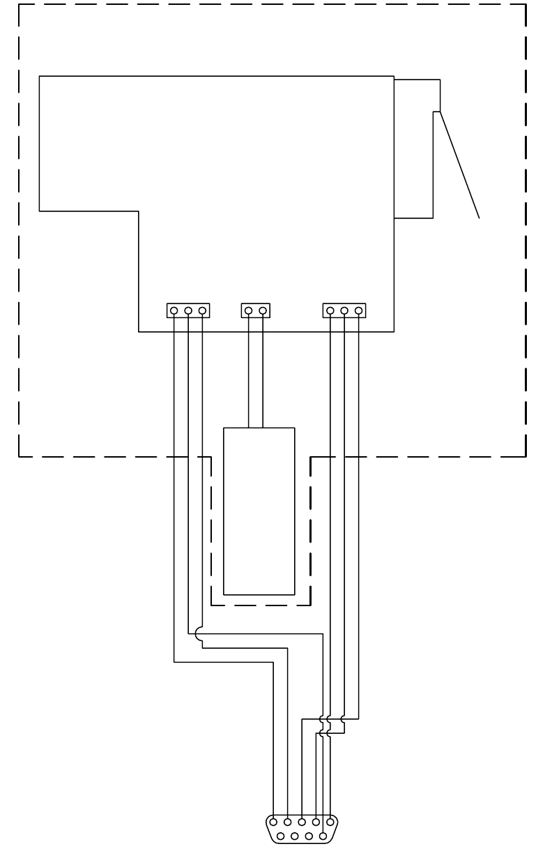
Electrical Diagram
#/),2%452.
#!3%
$)30%.3%#/--!.$
37)4#(2%452.
$)30%.3%!#4)6%
$)30%.3%2%15%34!#4)6%
!2'5.(!.$,%
'5.#)2#5)4"/!2$
3/,%./)$6!,6%
*
*
*
ti12351a
Technical Data
312888D 31
Technical Data
† Flow rate depends on pump sizes, hose diameter, hose length, and impingers
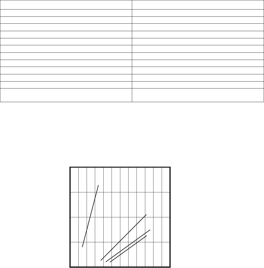
Performance Charts
Category Data
Maximum Fluid Working Pressure 2000 psi (13.8 MPa, 138 bar)
Minimum Air Inlet Pressure 90 psi (0.62 MPa, 6.2 bar)
Maximum Air Inlet Pressure 120 psi (0.84 MPa, 8.4 bar)
Maximum Output (flow rate) † 40 lb/min (18.1 kg/min)
Air Inlet Size 1/4 npt, quick disconnect nipple
A Component (ISO) Inlet Size #5 JIC
R Component (Resin) Inlet Size #6 JIC
Length 12.5 in. (318 mm)
Height 9.5 in. (241 mm)
Width 2.8 in. (71 mm)
Weight 6.7 lbs (3.0 kg)
Wetted Parts Stainless Steel, Zinc Plated Carbon Steel, Black Oxide
Coated Carbon Steel, Tool Steel, 6/6 Nylon, Acetal
Flow Rate in lb/min (kg/min)
Pressure in psi (MPa, bar)
05
(2.3)
25
(11.4)
15
(6.8)
35
(15.9)
45
(20.5)
2000
(13.8, 138)
1500
(10.3, 103)
1000
(6.9, 69)
500
(3.4, 34)
KEY
A = AR-C 23-B-1 impingers
B = AR-C 36-C-1 Impingers
C = AR-C 58-C-1 impingers
D = AR-D 59-D-1 front
impinger and AR-D 58-C-1
rear impinger
55
(25.0)
A
B
C
D
Impingers Performance Chart
Impingers tested with 100-150 centipoise Mesamoll with a specific gravity of
1.055.

All written and visual data contained in this document reflects the latest product information available at the time of publication.
Graco reserves the right to make changes at any time without notice.
This manual contains English. MM 312888
Graco Headquarters: Minneapolis
International Offices: Belgium, China, Japan, Korea
GRACO INC. P.O. BOX 1441 MINNEAPOLIS, MN 55440-1441
Copyright 2008, Graco Inc. is registered to I.S. EN ISO 9001
www.graco.com
Revised 11/2008
Graco Standard Warranty
Graco warrants all equipment referenced in this document which is manufactured by Graco and bearing its name to be free from defects in
material and workmanship on the date of sale to the original purchaser for use. With the exception of any special, extended, or limited warranty
published by Graco, Graco will, for a period of twelve months from the date of sale, repair or replace any part of the equipment determined by
Graco to be defective. This warranty applies only when the equipment is installed, operated and maintained in accordance with Graco’s written
recommendations.
This warranty does not cover, and Graco shall not be liable for general wear and tear, or any malfunction, damage or wear caused by faulty
installation, misapplication, abrasion, corrosion, inadequate or improper maintenance, negligence, accident, tampering, or substitution of
non-Graco component parts. Nor shall Graco be liable for malfunction, damage or wear caused by the incompatibility of Graco equipment with
structures, accessories, equipment or materials not supplied by Graco, or the improper design, manufacture, installation, operation or
maintenance of structures, accessories, equipment or materials not supplied by Graco.
This warranty is conditioned upon the prepaid return of the equipment claimed to be defective to an authorized Graco distributor for verification of
the claimed defect. If the claimed defect is verified, Graco will repair or replace free of charge any defective parts. The equipment will be returned
to the original purchaser transportation prepaid. If inspection of the equipment does not disclose any defect in material or workmanship, repairs will
be made at a reasonable charge, which charges may include the costs of parts, labor, and transportation.
THIS WARRANTY IS EXCLUSIVE, AND IS IN LIEU OF ANY OTHER WARRANTIES, EXPRESS OR IMPLIED, INCLUDING BUT NOT LIMITED
TO WARRANTY OF MERCHANTABILITY OR WARRANTY OF FITNESS FOR A PARTICULAR PURPOSE.
Graco’s sole obligation and buyer’s sole remedy for any breach of warranty shall be as set forth above. The buyer agrees that no other remedy
(including, but not limited to, incidental or consequential damages for lost profits, lost sales, injury to person or property, or any other incidental or
consequential loss) shall be available. Any action for breach of warranty must be brought within two (2) years of the date of sale.
GRACO MAKES NO WARRANTY, AND DISCLAIMS ALL IMPLIED WARRANTIES OF MERCHANTABILITY AND FITNESS FOR A
PARTICULAR PURPOSE, IN CONNECTION WITH ACCESSORIES, EQUIPMENT, MATERIALS OR COMPONENTS SOLD BUT NOT
MANUFACTURED BY GRACO. These items sold, but not manufactured by Graco (such as electric motors, switches, hose, etc.), are subject to
the warranty, if any, of their manufacturer. Graco will provide purchaser with reasonable assistance in making any claim for breach of these
warranties.
In no event will Graco be liable for indirect, incidental, special or consequential damages resulting from Graco supplying equipment hereunder, or
the furnishing, performance, or use of any products or other goods sold hereto, whether due to a breach of contract, breach of warranty, the
negligence of Graco, or otherwise.
FOR GRACO CANADA CUSTOMERS
The Parties acknowledge that they have required that the present document, as well as all documents, notices and legal proceedings entered into,
given or instituted pursuant hereto or relating directly or indirectly hereto, be drawn up in English. Les parties reconnaissent avoir convenu que la
rédaction du présente document sera en Anglais, ainsi que tous documents, avis et procédures judiciaires exécutés, donnés ou intentés, à la suite
de ou en rapport, directement ou indirectement, avec les procédures concernées.
Graco Information
TO PLACE AN ORDER,
contact your Graco distributor or call to identify the nearest distributor.
Phone: 612-623-6921 or Toll Free: 1-800-328-0211 Fax: 612-378-3505
