Graco 313876F Pd44 Metering Valves And Feed Systems Users Manual Systems, Operation Maintenance, English
2015-04-02
: Graco Graco-313876F-Pd44-Metering-Valves-And-Feed-Systems-Users-Manual-686577 graco-313876f-pd44-metering-valves-and-feed-systems-users-manual-686577 graco pdf
Open the PDF directly: View PDF ![]() .
.
Page Count: 44
- Related Manuals
- Models
- Warnings
- Product Configurator
- Accessories
- Isocyanate Conditions
- Material Self-ignition
- Moisture Sensitivity of Isocyanates
- Keep Components A and B Separate
- Foam Resins with 245 fa Blowing Agents
- Changing Materials
- Grounding
- Overview
- Component Identification
- Setup
- Startup
- Adjusting the Shot Size
- Ratio Check
- Operation
- Pressure Relief Procedure
- Shutdown
- Maintenance
- Troubleshooting
- Schematics
- Rebuild
- Electrical Requirements
- Technical Data
- Graco Standard Warranty
- Graco Information
313876F
ENG
Operation - Maintenance
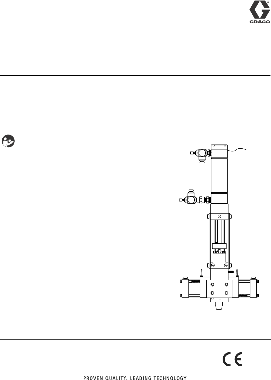
PD44
Metering Valves and Feed Systems
Meter, mix, and dispense system for precise two-component micro-dispensing of sealants
and adhesives.
Not approved for use in European explosive atmosphere locations.
See page 3 for model information, including maximum
working pressure and approvals. See page 6 for prod-
uct configuration information.
Important Safety Instructions
Read all warnings and instructions in this man-
ual. Save these instructions.
Linear Resistive Transducer PD44 Meter-
ing Valve shown, Feed Systems not shown
2313876F
Contents
Related Manuals . . . . . . . . . . . . . . . . . . . . . . . . . . . 3
Models . . . . . . . . . . . . . . . . . . . . . . . . . . . . . . . . . . . 3
Warnings . . . . . . . . . . . . . . . . . . . . . . . . . . . . . . . . . 4
Product Configurator . . . . . . . . . . . . . . . . . . . . . . . 6
Accessories . . . . . . . . . . . . . . . . . . . . . . . . . . . . . . 11
Isocyanate Conditions . . . . . . . . . . . . . . . . . . . . . 13
Material Self-ignition . . . . . . . . . . . . . . . . . . . . . . 13
Moisture Sensitivity of Isocyanates . . . . . . . . . . . 13
Keep Components A and B Separate . . . . . . . . . 13
Foam Resins with 245 fa Blowing Agents . . . . . . 13
Changing Materials . . . . . . . . . . . . . . . . . . . . . . . . 13
Grounding . . . . . . . . . . . . . . . . . . . . . . . . . . . . . . . 14
Overview . . . . . . . . . . . . . . . . . . . . . . . . . . . . . . . . . 14
Component Identification . . . . . . . . . . . . . . . . . . . 15
Typical System Configurations . . . . . . . . . . . . . 15
Typical Feed System Components . . . . . . . . . . 16
Micrometer PD44 Metering Valve . . . . . . . . . . . 18
LRT PD44 Metering Valve . . . . . . . . . . . . . . . . . 19
Motor Driven PD44 Metering Valve . . . . . . . . . . 20
Setup . . . . . . . . . . . . . . . . . . . . . . . . . . . . . . . . . . . . 21
Typical Installation . . . . . . . . . . . . . . . . . . . . . . . 21
Tank Level Sensor Wiring Schematic . . . . . . . . 22
Valve Mounting Diagram . . . . . . . . . . . . . . . . . . 22
Motor Mounting Diagram . . . . . . . . . . . . . . . . . . 23
Custom Drive Mounting Diagram . . . . . . . . . . . 23
Startup . . . . . . . . . . . . . . . . . . . . . . . . . . . . . . . . . . 24
Adjusting the Shot Size . . . . . . . . . . . . . . . . . . . . 25
Micrometer PD44 Only . . . . . . . . . . . . . . . . . . . 25
LRT and Motor Driven PD44 . . . . . . . . . . . . . . . 25
Ratio Check . . . . . . . . . . . . . . . . . . . . . . . . . . . . . . 26
Operation . . . . . . . . . . . . . . . . . . . . . . . . . . . . . . . . 27
Sequence of Operation . . . . . . . . . . . . . . . . . . . 27
Pressure Relief Procedure . . . . . . . . . . . . . . . . . . 28
Shutdown . . . . . . . . . . . . . . . . . . . . . . . . . . . . . . . . 28
Maintenance . . . . . . . . . . . . . . . . . . . . . . . . . . . . . . 28
Troubleshooting . . . . . . . . . . . . . . . . . . . . . . . . . . . 29
Schematics . . . . . . . . . . . . . . . . . . . . . . . . . . . . . . . 29
Rebuild . . . . . . . . . . . . . . . . . . . . . . . . . . . . . . . . . . 30
Wetted Section Disassembly . . . . . . . . . . . . . . 30
Wetted Section Reassembly . . . . . . . . . . . . . . . 32
Spool Valve Rebuild . . . . . . . . . . . . . . . . . . . . . 33
Wetted Section Rebuild . . . . . . . . . . . . . . . . . . . 34
Micrometer Drive Rebuild
(Micrometer PD44 Only) . . . . . . . . . . . . . . . 37
Electrical Requirements . . . . . . . . . . . . . . . . . . . . 39
Technical Data . . . . . . . . . . . . . . . . . . . . . . . . . . . . 42
Graco Ohio Standard Warranty . . . . . . . . . . . . . . 44
Graco Ohio Information . . . . . . . . . . . . . . . . . . . . . 44

Related Manuals
313876F 3
Related Manuals
Manuals are available at www.graco.com
Component manuals in U.S. English.
Models
* If a custom PD44 is ordered, it will not be CE
approved unless otherwise noted.
PD44 Manuals
Part Description
313877 PD44 Control Box Setup - Operation
3A0987 PD44 Parts
Feed System Manuals
306565 Air-Driven, Stainless Steel Agitators
307043 Monark Air Motor
308116 Severe-Duty, UHMWPE/PTFE or PTFE
Packed Stainless Steel Pumps
308167 Low Volume Air Regulators
308168 High Volume Air Regulators
308169 Air Filters, Lubricators and Kits
309306 Air-Operated Husky Diaphragm Pumps
312376 Stainless Steel Agitator Kit
313526 Check-Mate® Pump Packages
3A1452 20 oz Cartridge
Metering Valve
Model
Max Outlet
Fluid Working
Pressure
psi (MPa, bar)
Max Air
Working
Pressure
psi (MPa, bar)
Max Inlet Working Pressure
psi (MPa, bar)
CE
Approved*Metal Sleeves Plastic Sleeves
Linear Resistive
Transducer (LRT)
2000 (14, 138) 100 (0.7, 7) 1200 (8, 83) 400 (2.8, 28) ✔
Micrometer 2000 (14, 138) 100 (0.7, 7) 1200 (8, 83) 400 (2.8, 28) ✔
Motor Driven 2000 (14, 138) 100 (0.7, 7) 1200 (8, 83) 400 (2.8, 28) ✔
Warnings
4313876F
Warnings
The following warnings are for the setup, use, grounding, maintenance, and repair of this equipment. The exclama-
tion point symbol alerts you to a general warning and the hazard symbol refers to procedure-specific risk. Refer back
to these warnings. Additional, product-specific warnings may be found throughout the body of this manual where
applicable.
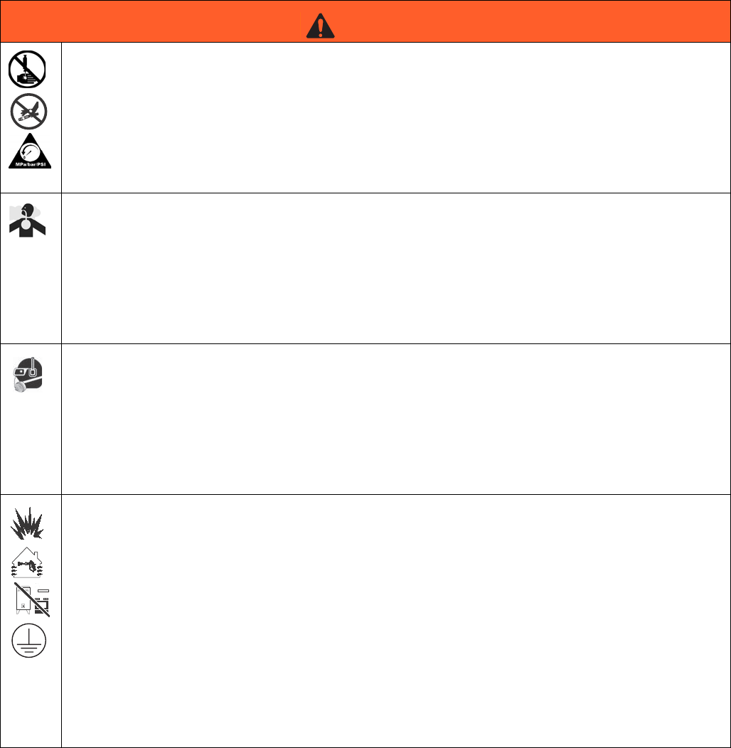
WARNING
SKIN INJECTION HAZARD
High-pressure fluid from gun, hose leaks, or ruptured components will pierce skin. This may look like just
a cut, but it is a serious injury that can result in amputation. Get immediate surgical treatment.
• Do not point gun at anyone or at any part of the body.
• Do not put your hand over the dispense outlet.
• Do not stop or deflect leaks with your hand, body, glove, or rag.
• Follow Pressure Relief Procedure in this manual, when you stop dispensing and before cleaning,
checking, or servicing equipment.
TOXIC FLUID OR FUMES HAZARD
Toxic fluids or fumes can cause serious injury or death if splashed in the eyes or on skin, inhaled, or
swallowed.
• Read MSDS’s to know the specific hazards of the fluids you are using.
• Store hazardous fluid in approved containers, and dispose of it according to applicable guidelines.
• Always wear impervious gloves when spraying or cleaning equipment.
• If this equipment is used with isocyanate material, see additional information on isocyanates in Iso-
cyanate Conditions Section of this manual.
PERSONAL PROTECTIVE EQUIPMENT
You must wear appropriate protective equipment when operating, servicing, or when in the operating
area of the equipment to help protect you from serious injury, including eye injury, inhalation of toxic
fumes, burns, and hearing loss. This equipment includes but is not limited to:
• Protective eyewear
• Clothing and respirator as recommended by the fluid and solvent manufacturer
•Gloves
• Hearing protection
FIRE AND EXPLOSION HAZARD
Flammable fumes, such as solvent and paint fumes, in work area can ignite or explode. To help prevent
fire and explosion:
• Use equipment only in well ventilated area.
• Eliminate all ignition sources; such as pilot lights, cigarettes, portable electric lamps, and plastic drop
cloths (potential static arc).
• Keep work area free of debris, including solvent, rags and gasoline.
• Do not plug or unplug power cords, or turn power or light switches on or off when flammable fumes
are present.
• Ground all equipment in the work area. See Grounding instructions.
• Use only grounded hoses.
• If there is static sparking or you feel a shock, stop operation immediately. Do not use equipment
until you identify and correct the problem.
• Keep a working fire extinguisher in the work area.
Warnings
313876F 5
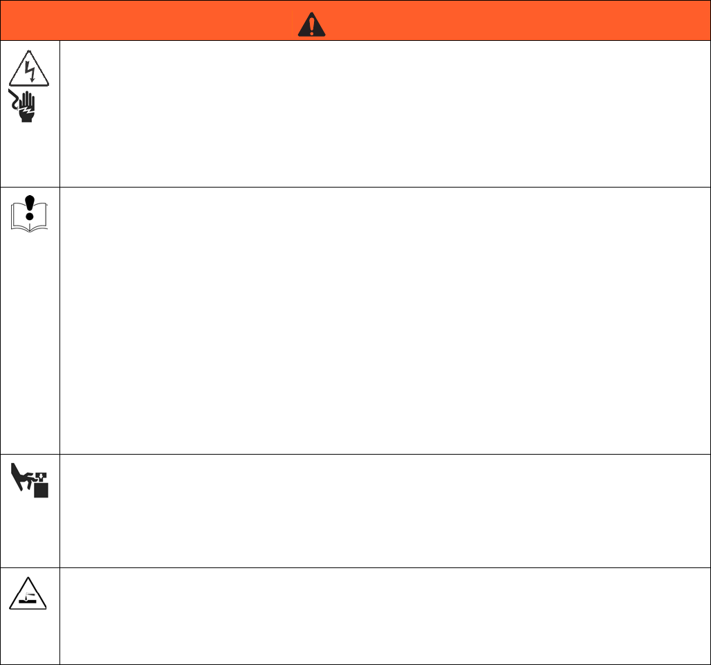
ELECTRIC SHOCK HAZARD
This equipment must be grounded. Improper grounding, setup, or usage of the system can cause elec-
tric shock.
• Turn off and disconnect power cord before servicing equipment.
• Use only grounded electrical outlets.
• Use only 3-wire extension cords.
• Ensure ground prongs are intact on power and extension cords.
• Do not expose to rain. Store indoors.
EQUIPMENT MISUSE HAZARD
Misuse can cause death or serious injury.
• Do not operate the unit when fatigued or under the influence of drugs or alcohol.
• Do not exceed the maximum working pressure or temperature rating of the lowest rated system
component. See Technical Data in all equipment manuals.
• Do not leave the work area while equipment is energized or under pressure. Turn off all equipment
and follow the Pressure Relief Procedure in this manual when equipment is not in use.
• Check equipment daily. Repair or replace worn or damaged parts immediately with genuine manu-
facturer’s replacement parts only.
• Do not alter or modify equipment.
• Use equipment only for its intended purpose. Call your distributor for information.
• Route hoses and cables away from traffic areas, sharp edges, moving parts, and hot surfaces.
• Do not kink or over bend hoses or use hoses to pull equipment.
• Keep children and animals away from work area.
• Comply with all applicable safety regulations.
MOVING PARTS HAZARD
Moving parts can pinch or amputate fingers and other body parts.
• Keep clear of moving parts.
• Do not operate equipment with protective guards or covers removed.
• Pressurized equipment can start without warning. Before checking, moving, or servicing equipment,
follow the Pressure Relief Procedure in this manual. Disconnect power or air supply.
PLASTIC PARTS CLEANING SOLVENT HAZARD
Use only compatible water-based solvents to clean plastic structural or pressure-containing parts. Many
solvents can degrade plastic parts and cause them to fail, which could cause serious injury or property
damage. See Technical Data in this and all other equipment instruction manuals. Read fluid and solvent
manufacturer’s warnings.
WARNING

Product Configurator
6313876F
Product Configurator
This system can be ordered with many different options as shown in the configurator below.
The following table applies to the PD44 configurations and indicates all of the options available for each letter shown
above.
PD44 C-A-BCD-EFG- H - I -J-K-L-M-NO-P-Q-RS-T-U-V-W- X
Configurator Series Level
Base Unit
High Volume Rod Material, Size
Low Volume Rod Material, Size
High Volume Spool
Low Volume Spool
Outlet Nose
Mixer
Controls
Power Cord
High Volume Feed
High Volume Feed Hose
High Volume Feed Options
Low Volume Feed
Low Volume Feed Hose
Low Volume Feed Options
Vacuum Pump(s)
Bench Stand
Seal Lubricant
Code A Part Base Unit
A964000 Micrometer PD44
B964001 Linear Resistive Transducer PD44
C 964002 Motor Driven PD44
Code B Part High Volume Rod Material
NOTE: See code CD for last two digits of part number
A9641__ Hardened Steel
B9642__ Stainless Steel, UHMW
C9643__ Tungsten Carbide, UHMW
Code
CD Part High Volume Rod Size
NOTE: See code B for first four digits of part number
01 ____01 1.25 mm rod diameter
02 ____02 1.38 mm rod diameter
03 ____03 1.50 mm rod diameter
04 ____04 1.63 mm rod diameter
05 ____05 1.75 mm rod diameter
06 ____06 2.00 mm rod diameter
07 ____07 2.13 mm rod diameter
08 ____08 2.25 mm rod diameter
09 ____09 2.38 mm rod diameter
10 ____10 2.50 mm rod diameter
11 ____11 2.63 mm rod diameter
12 ____12 2.75 mm rod diameter
13 ____13 3.00 mm rod diameter
14 ____14 3.13 mm rod diameter
15 ____15 3.25 mm rod diameter
16 ____16 3.38 mm rod diameter
17 ____17 3.50 mm rod diameter
18 ____18 3.63 mm rod diameter
19 ____19 3.75 mm rod diameter
20 ____20 4.00 mm rod diameter
21 ____21 4.25 mm rod diameter
22 ____22 4.50 mm rod diameter
23 ____23 4.63 mm rod diameter
24 ____24 4.75 mm rod diameter
25 ____25 4.88 mm rod diameter
26 ____26 5.00 mm rod diameter
27 ____27 5.13 mm rod diameter
28 ____28 5.25 mm rod diameter
29 ____29 5.50 mm rod diameter
30 ____30 5.75 mm rod diameter
31 ____31 6.00 mm rod diameter
32 ____32 6.13 mm rod diameter
33 ____33 6.25 mm rod diameter
34 ____34 6.38 mm rod diameter
35 ____35 6.50 mm rod diameter
36 ____36 6.63 mm rod diameter
37 ____37 6.75 mm rod diameter
38 ____38 7.00 mm rod diameter
39 ____39 7.25 mm rod diameter
40 ____40 7.50 mm rod diameter
41 ____41 7.63 mm rod diameter
42 ____42 7.75 mm rod diameter
43 ____43 7.88 mm rod diameter
44 ____44 8.00 mm rod diameter

Product Configurator
313876F 7
Code E Part Low Volume Rod Material
NOTE: See code FG for last two digits of part number
A9641__ Hardened Steel
B9642__ Stainless Steel, UHMW
C9643__ Tungsten Carbide, UHMW
Code FG Part Low Volume Rod Size
NOTE: See code E for first four digits of part number
01 ____01 1.25 mm rod diameter
02 ____02 1.38 mm rod diameter
03 ____03 1.50 mm rod diameter
04 ____04 1.63 mm rod diameter
05 ____05 1.75 mm rod diameter
06 ____06 2.00 mm rod diameter
07 ____07 2.13 mm rod diameter
08 ____08 2.25 mm rod diameter
09 ____09 2.38 mm rod diameter
10 ____10 2.50 mm rod diameter
11 ____11 2.63 mm rod diameter
12 ____12 2.75 mm rod diameter
13 ____13 3.00 mm rod diameter
14 ____14 3.13 mm rod diameter
15 ____15 3.25 mm rod diameter
16 ____16 3.38 mm rod diameter
17 ____17 3.50 mm rod diameter
18 ____18 3.63 mm rod diameter
19 ____19 3.75 mm rod diameter
20 ____20 4.00 mm rod diameter
21 ____21 4.25 mm rod diameter
22 ____22 4.50 mm rod diameter
23 ____23 4.63 mm rod diameter
24 ____24 4.75 mm rod diameter
25 ____25 4.88 mm rod diameter
26 ____26 5.00 mm rod diameter
27 ____27 5.13 mm rod diameter
28 ____28 5.25 mm rod diameter
29 ____29 5.50 mm rod diameter
30 ____30 5.75 mm rod diameter
31 ____31 6.00 mm rod diameter
32 ____32 6.13 mm rod diameter
33 ____33 6.25 mm rod diameter
34 ____34 6.38 mm rod diameter
35 ____35 6.50 mm rod diameter
36 ____36 6.63 mm rod diameter
37 ____37 6.75 mm rod diameter
38 ____38 7.00 mm rod diameter
39 ____39 7.25 mm rod diameter
40 ____40 7.50 mm rod diameter
41 ____41 7.63 mm rod diameter
42 ____42 7.75 mm rod diameter
43 ____43 7.88 mm rod diameter
44 ____44 8.00 mm rod diameter
Code H Part High Volume Spool
1964003 High viscosity, HS
2964004 High viscosity, Stainless Steel/UHMWPE
3964005 High viscosity, TC/UHMWPE
4964006 Low viscosity, Stainless Steel
Code I Part Low Volume Spool
1964011 High viscosity, HS
2964012 High viscosity, Stainless Steel/UHMWPE
3964013 High viscosity, TC/UHMWPE
4964014 Low viscosity, Stainless Steel
Code J Part Outlet Nose
1964020 Luer lock, equal ports, no check valves
2964021 Luer lock, equal ports, dual check valves
3964022 Equal ports, 7/8-9, no check valves
4964023 Large and small ports, 7/8-9, no check
valves
5964024 Large and small ports, 7/8-9, single
check valve
6964025 Dual small ports, 7/8-9, no check valves
7964026 Dual small ports, 7/8-9 dual check valves
Code K Part Mixer
1964027 1/8-24 Luer Lock inlet and outlet, 0.5 cc
2964028 3/16-32 bell mouth inlet, luer lock outlet,
2.0 cc
3964029 1/4-24 bell mouth inlet, luer lock outlet,
4.0 cc
4964030 1/4-32 bell mouth inlet, luer lock outlet,
5.5 cc
5964031 1/4-48 bell mouth inlet, luer lock outlet,
8.0 cc
6964032 3/16-32 bell mouth inlet, tapered outlet,
1.5 cc
7964033 1/4-24 bell mouth inlet, tapered outlet,
3.5 cc
8964034 3/16-24 bell mouth inlet, tapered outlet,
1.0 cc

Product Configurator
8313876F
Code L Part Controls
1964035 Pneumatic, micrometer, wire harness
only
2964036 Pneumatic, micrometer, HMI controls, low
level
3964037 Pneumatic, micrometer, HMI controls, low
level, I/O package
4964038 Pneumatic, micrometer, HMI controls, low
level, high level
5964039 Pneumatic, micrometer, HMI controls, low
level, high level, I/O package
6964040 Pneumatic, linear resistive transducer,
wire harness only
7964041 Pneumatic, linear resistive transducer,
HMI controls, low level
8964042 Pneumatic, linear resistive transducer,
HMI controls, low level, I/O package
9964043 Pneumatic, linear resistive transducer,
HMI controls, low level, high level
A964044 Pneumatic, linear resistive transducer,
HMI controls, low level, high level, I/O
package
B964045 Motor driven, I/O, wire harness only
C964046 Stepper motor, HMI control, low level,
high level, I/O package
Code M Part Power Cord
1121055 120 VAC, North American cord set
2121054 250 VAC, 1 phase, no plug
3121056 10 amp, 250 volt, continental Europe
4121057 10 amp, 250 volt, United Kingdom and
Ireland
5121058 10 amp, 250 volt, Israel
6124864 10 amp, 250 volt, Australia
7124861 10 amp, 250 volt, Italy
8124863 10 amp, 250 volt, Switzerland
9124862 10 amp, 250 volt, Denmark
A121060 10 amp, 250 volt, India
N-- None
Code
NO Part High Volume Feed
01 964050 20 oz cartridge feed with mounting post
02 964051 1 gallon pail Ram and transfer pump
03 964052 5 gallon pail cover with diaphragm pump
04 964053 5 gallon pail cover diaphragm pump and
agitator
05 964054 5 gallon pail cover and 5:1 transfer pump
06 964055 5 gallon pail cover, 1:1 pump with dip
tube for moisture sensitive materials
07 964056 5 gallon single post Ram with 11:1 pump,
mild steel
08 964057 5 gallon single post Ram with 11:1 pump,
stainless steel
09 964058 5 gallon tank, support and diaphragm
pump, mild steel
10 964059 5 gallon tank, support, diaphragm pump
and agitator, mild steel
11 964060 5 gallon tank, support, diaphragm pump,
agitator and vacuum fill, mild steel
12 964061 5 gallon tank, support, diaphragm pump,
stainless steel
13 964062 5 gallon tank, support, diaphragm pump,
agitator, stainless steel
14 964063 5 gallon tank, support, diaphragm pump,
agitator, vacuum fill, stainless steel
15 964064 5 gallon tank, support and 5:1 pump, mild
steel
16 964065 5 gallon tank, support, 5:1 pump, agitator,
mild steel
17 964066 5 gallon tank, support, 5:1 pump, agitator,
vacuum fill, mild steel
18 964067 5 gallon tank, support, 5:1 pump, stain-
less steel

Product Configurator
313876F 9
19 964068 5 gallon tank, support, 5:1 pump, agitator,
stainless steel
20 964069 5 gallon tank, support, 5:1 pump, agitator,
vacuum fill, stainless steel
21 964070 10 gallon tank, support, diaphragm
pump, mild steel
22 964071 10 gallon tank, support, diaphragm
pump, agitator, mild steel
23 964072 10 gallon tank, support, diaphragm
pump, agitator, vacuum fill, mild steel
24 964073 10 gallon tank, support, diaphragm
pump, stainless steel
25 964074 10 gallon tank, support, diaphragm
pump, agitator, stainless steel
26 964075 10 gallon tank, support, diaphragm
pump, agitator, vacuum fill, stainless steel
27 964076 10 gallon tank, support, 5:1 pump, mild
steel
28 964077 10 gallon tank, support, 5:1 pump, agita-
tor, mild steel
29 964078 10 gallon tank, support, 5:1 pump, agita-
tor, vacuum fill, mild steel
30 964079 10 gallon tank, support, 5:1 pump, stain-
less steel
31 964080 10 gallon, tank, support, 4:1 pump, agita-
tor, stainless steel
32 964081 10 gallon tank, support, 5:1 pump, agita-
tor, vacuum fill, stainless steel
NN -- None
Code P Part High Volume Feed Hose
1964082 1/2 in. x 8 ft PTFE and stainless steel
hose, stainless steel fittings
3964084 1/2 in. x 10 ft PTFE and stainless steel
hose, stainless steel fittings
5964086 1/2 in. x 15 ft PTFE and stainless steel
hose, stainless steel fittings
N-- None
Code Q Part High Volume Feed
A964088 Dessicant dryers for tank lids
B964089 Nitrogen harness assembly for tank lids
C964090 Low level sensor 11:1 Ram only
N-- None
Code RS Part Low Volume Feed
01 964050 20 oz cartridge feed with mounting post
02 964051 1 gallon pail Ram and transfer pump
03 964052 5 gallon pail cover with diaphragm pump
04 964053 5 gallon pail cover diaphragm pump and
agitator
05 964054 5 gallon pail cover and 5:1 transfer pump
06 964055 5 gallon pail cover, 1:1 pump with dip
tube for moisture sensitive materials
07 964056 5 gallon single post Ram with 11:1 pump,
mild steel
08 964057 5 gallon single post Ram with 11:1 pump,
stainless steel
09 964058 5 gallon tank, support and diaphragm
pump, mild steel
10 964059 5 gallon tank, support, diaphragm pump
and agitator, mild steel
11 964060 5 gallon tank, support, diaphragm pump,
agitator and vacuum fill, mild steel
12 964061 5 gallon tank, support, diaphragm pump,
stainless steel
13 964062 5 gallon tank, support, diaphragm pump,
agitator, stainless steel
14 964063 5 gallon tank, support, diaphragm pump,
agitator, vacuum fill, stainless steel
15 964064 5 gallon tank, support and 5:1 pump, mild
steel
16 964065 5 gallon tank, support, 5:1 pump, agitator,
mild steel
17 964066 5 gallon tank, support, 5:1 pump, agitator,
vacuum fill, mild steel
18 964067 5 gallon tank, support, 5:1 pump, stain-
less steel

Product Configurator
10 313876F
19 964068 5 gallon tank, support, 5:11 pump, agita-
tor, stainless steel
20 964069 5 gallon tank, support, 5:1 pump, agitator,
vacuum fill, stainless steel
21 964070 10 gallon tank, support, diaphragm
pump, mild steel
22 964071 10 gallon tank, support, diaphragm
pump, agitator, mild steel
23 964072 10 gallon tank, support, diaphragm
pump, agitator, vacuum fill, mild steel
24 964073 10 gallon tank, support, diaphragm
pump, stainless steel
25 964074 10 gallon tank, support, diaphragm
pump, agitator, stainless steel
26 964075 10 gallon tank, support, diaphragm
pump, agitator, vacuum fill, stainless steel
27 964076 10 gallon tank, support, 5:1 pump, mild
steel
28 964077 10 gallon tank, support, 5:1 pump, agita-
tor, mild steel
29 964078 10 gallon tank, support, 5:1 pump, agita-
tor, vacuum fill, mild steel
30 964079 10 gallon tank, support, 5:1 pump, stain-
less steel
31 964080 10 gallon, tank, support, 4:1 pump, agita-
tor, stainless steel
32 964081 10 gallon tank, support, 5:1 pump, agita-
tor, vacuum fill, stainless steel
NN -- None
Code T Part Low Volume Feed Hose
1964082 1/2 in. x 8 ft PTFE and stainless steel
hose, stainless steel fittings
3964084 1/2 in. x 10 ft PTFE and stainless steel
hose, stainless steel fittings
5964086 1/2 in. x 15 ft PTFE and stainless steel
hose, stainless steel fittings
7-- None
Code U Part Low Volume Feed
A964088 Dessicant dryers for tank lids
B964089 Nitrogen harness assembly for tank lids
C964090 Low level sensor 11:1 Ram only
N-- None
Code V Part Vacuum Pump(s)
1964091 1-115V, 1 phase, 6.9 cfm, inlet and outlet
filter, 1 in. hose to single tank
2964092 1-115V, 1 phase, 6.9 cfm, inlet and outlet
filter, 1 in. hose to two tanks
3964093 1-230V, 1 phase, 6.9 cfm, inlet and outlet
filter, 1 in. hose to single tank
4964094 1-230V, 1 phase, 6.9 cfm, inlet and outlet
filter, 1 in. hose to two tanks
N-- None
Code W Part Bench Stand
A964095 Adjustable height bench stand
N-- None
Code X Part Seal Lubricant
A964096 Non-silicone seal lubricant
B964097 Silicone seal lubricant

Accessories
313876F 11
Accessories
Mixer Kits with Shroud
Mixer Packs
Part Description
964034 Mixer, Kit, 3/16 in. (4.8mm) x 24, 10
taper tip mixers with shroud
964032 Mixer, Kit, 3/16 in. (4.8mm) x 32, 10
taper tip mixers with shroud
964028 Mixer, Kit, 3/16 in. (4.8mm) x 32, 10
Luer Lock tip mixers with shroud/sleeve
964033 Mixer, Kit, 1/4 in. (6.5mm) x 24, 10
taper tip mixers with shroud
964029 Mixer, Kit, 1/4 in. (6.5mm) x 24, 10 Luer
Lock tip mixers with shroud/sleeve
964030 Mixer, Kit, 1/4 in. (6.5mm) x 32, 10 Luer
Lock tip mixers with shroud/sleeve
964031 Mixer, Kit, 1/4 in. (6.5mm) x 48, 10 Luer
Lock tip mixers with shroud/sleeve
Part Description
964027 Mixer, 1/8 in. (3.2mm) x 24 Luer Lock
inlet/tip, 10 Pack
16D962 Mixer, 1/8 in. (3.2mm) x 24 Luer Lock
inlet/tip, 50 Pack
16D963 Mixer, 1/8 in. (3.2mm) x 24 Luer Lock
inlet/tip, 250 Pack
16D978 Mixer, 3/16 in. (4.8mm) x 24 taper tip,
50 Pack
16D979 Mixer, 3/16 in. (4.8mm) x 24 taper tip,
250 Pack
LC0077 Mixer, 3/16 in. (4.8mm) x 32 taper tip,
50 Pack
LC0084 Mixer, 3/16 in. (4.8mm) x 32 taper tip,
250 Pack
LC0082 Mixer, 3/16 in. (4.8mm) x 32 Luer Lock
tip, 50 Pack
LC0090 Mixer, 3/16 in. (4.8mm) x 32 Luer Lock
tip, 250 Pack
LC0078 Mixer, 1/4 in. (6.5mm) x 24 taper tip
mixer, 50 Pack
LC0085 Mixer, 1/4 in. (6.5mm) x 24 taper tip
mixer, 250 Pack
LC0083 Mixer, 1/4 in. (6.5mm) x 24 Luer Lock
tip, 50 Pack
LC0089 Mixer, 1/4 in. (6.5mm) x 24 Luer Lock
tip, 250 Pack
16D968 Mixer, 1/4 in. (6.5mm) x 32 Luer Lock
tip, 50 Pack
16D969 Mixer, 1/4 in. (6.5mm) x 32 Luer Lock
tip, 250 Pack
16D970 Mixer, 1/4 in. (6.5mm) x 48 Luer Lock
tip, 50 Pack
16D973 Mixer, 1/4 in. (6.5mm) x 48 Luer Lock
tip, 250 Pack
Part Description

Accessories
12 313876F
O-Rings and Seals
Needles
Part Description
24E247 Kit, O-ring, chemical resistant, PD44
24E248 Kit, Seal, Spool, H.V., PD44
24E249 Kit, Seal, Spool, L.V., PD44
16B265 Seal, Posipack, 1.25, ZAP
16B266 Seal, Posipack, 1.38, ZAP
16B267 Seal, Posipack, 1.50, ZAP
16B268 Seal, Posipack, 1.63, ZAP
16B269 Seal, Posipack, 1.75, ZAP
16B270 Seal, Posipack, 2.00, ZAP
16B271 Seal, Posipack, 2.13, ZAP
16B272 Seal, Posipack, 2.25, ZAP
16B273 Seal, Posipack, 2.38, ZAP
16B274 Seal, Posipack, 2.50, ZAP
16B275 Seal, Posipack, 2.63, ZAP
16B276 Seal, Posipack, 2.75, ZAP
16B277 Seal, Posipack, 3.00, ZAP
16B278 Seal, Posipack, 3.13, ZAP
16B279 Seal, Posipack, 3.25, ZAP
16B280 Seal, Posipack, 3.38, ZAP
16B281 Seal, Posipack, 3.50, ZAP
16B282 Seal, Posipack, 3.63, ZAP
16B283 Seal, Posipack, 3.75, ZAP
16B284 Seal, Posipack, 4.00, ZAP
16B285 Seal, Posipack, 4.25, ZAP
16B286 Seal, Posipack, 4.50, ZAP
16B287 Seal, Posipack, 4.63, ZAP
16B288 Seal, Posipack, 4.75, ZAP
16B289 Seal, Posipack, 4.88, ZAP
16B290 Seal, Posipack, 5.00, ZAP
16B291 Seal, Posipack, 5.13, ZAP
16B292 Seal, Posipack, 5.25, ZAP
16B293 Seal, Posipack, 5.50, ZAP
16B294 Seal, Posipack, 5.75, ZAP
16B295 Seal, Posipack, 6.00, ZAP
16B296 Seal, Posipack, 6.13, ZAP
16B297 Seal, Posipack, 6.25, ZAP
16B298 Seal, Posipack, 6.38, ZAP
16B299 Seal, Posipack, 6.50, ZAP
16B300 Seal, Posipack, 6.63, ZAP
16B301 Seal, Posipack, 6.75, ZAP
16B302 Seal, Posipack, 7.00, ZAP
16B303 Seal, Posipack, 7.25, ZAP
16B304 Seal, Posipack, 7.50, ZAP
16B305 Seal, Posipack, 7.63, ZAP
16B306 Seal, Posipack, 7.75, ZAP
16B307 Seal, Posipack, 7.88, ZAP
16B450 Seal, Posipack, 8.00, ZAP
Part Description
Part Description
E4000025-50 Needle, Luer Lock, Sampler Package
(10 each 14 ga x 1/2 in., 16 ga x
1/2 in., 18 ga x 1/2 in., 20 ga x 1/2 in.,
22 ga x 1/2 in.)
E4000001-50 Needle, Luer Lock, 14 Gauge x 1/2 in.,
50 Pack
E4000004-50 Needle, Luer Lock, 15 Gauge x 1/2 in.,
50 Pack
E4000005-50 Needle, Luer Lock, 16 Gauge x 1 in.,
50 Pack
E4000006-50 Needle, Luer Lock, 18 Gauge x 1 in.,
50 Pack
E4000011-50 Needle, Luer Lock, 22 Gauge x 1/2 in.,
50 Pack
E4000014-50 Needle, Luer Lock, 14 Gauge x 1 in.,
50 Pack
E4000024-50 Needle, Luer Lock, 23 Gauge x 1/2 in.,
50 Pack
E4000088-50 Needle, Luer Lock, 16 Gauge x 1/2 in.,
50 Pack
Part Description
Isocyanate Conditions
313876F 13
Isocyanate Conditions
Material Self-ignition
Moisture Sensitivity of
Isocyanates
Isocyanates (ISO) are catalysts used in two component
foam and polyurea coatings. ISO will react with moisture
(such as humidity) to form small, hard, abrasive crystals,
which become suspended in the fluid. Eventually a film
will form on the surface and the ISO will begin to gel,
increasing in viscosity. If used, this partially cured ISO
will reduce performance and the life of all wetted parts.
NOTE: The amount of film formation and rate of crystal-
lization varies depending on the blend of ISO, the
humidity, and the temperature.
To prevent exposing ISO to moisture:
• Always use a sealed container with a desiccant
dryer in the vent, or a nitrogen atmosphere. Never
store ISO in an open container.
• Keep the ISO lube pump reservoir (if installed) filled
with Graco Throat Seal Liquid (TSL), Part 206995.
The lubricant creates a barrier between the ISO and
the atmosphere.
• Use moisture-proof hoses specifically designed for
ISO, such as those supplied with your system.
• Never use reclaimed solvents, which may contain
moisture. Always keep solvent containers closed
when not in use.
• Never use solvent on one side if it has been contam-
inated from the other side.
• Always lubricate threaded parts with ISO pump oil
or grease when reassembling.
Keep Components A and
B Separate
Foam Resins with 245 fa
Blowing Agents
Some foam blowing agents will froth at temperatures
above 90°F (33°C) when not under pressure, especially
if agitated. To reduce frothing, minimize preheating in a
circulation system.
Changing Materials
• When changing materials, flush the equipment mul-
tiple times to ensure it is thoroughly clean.
• Always clean the fluid inlet strainers after flushing.
• Check with your material manufacturer for chemical
compatibility.
• Most materials use ISO on the A side, but some use
ISO on the B side.
• Epoxies often have amines on the B (hardener)
side. Polyureas often have amines on the B (resin)
side.
Spraying or dispensing materials containing isocya-
nates creates potentially harmful mists, vapors, and
atomized particulates.
Read material manufacturer’s warnings and material
MSDS to know specific hazards and precautions
related to isocyanates.
Prevent inhalation of isocyanate mists, vapors, and
atomized particulates by providing sufficient ventila-
tion in the work area. If sufficient ventilation is not
available, a supplied-air respirator is required for
everyone in the work area.
To prevent contact with isocyanates, appropriate per-
sonal protective equipment, including chemically
impermeable gloves, boots, aprons, and goggles, is
also required for everyone in the work area.
Some materials may become self-igniting if applied
too thickly. Read material manufacturer’s warnings
and material MSDS.
NOTICE
To prevent cross-contamination of the equipment’s
wetted parts, never interchange component A (isocy-
anate) and component B (resin) parts.

Grounding
14 313876F
Grounding
This product must be grounded. In the event of an elec-
trical short circuit, grounding reduces the risk of electric
shock by providing an escape wire for the electric cur-
rent.
Metering valve: attach ground wire from grounding lug
to true earth ground. See Component Identification
starting on page 15.
Fluid hoses: use only electrically conductive hoses.
Feed system components: attach ground wire from
grounding lug to true earth ground. See feed system
manual for grounding points. See Related Manuals on
page 3.
Fluid supply container: follow local code.
Solvent pails used when flushing: follow local code.
Use only conductive metal pails, placed on a grounded
surface. Do not place the pail on a nonconductive sur-
face, such as paper or cardboard, which interrupts
grounding continuity.
Overview
This plural component meter, mix, and dispense device
accurately meters liquid and semi-paste materials.
The machine is ideal for a two-component application
requiring very small and precisely mixed shots.
The ratio of the pneumatic cylinder area to pump shaft
area provides the adjustable pressure intensification
needed to move the separate liquids through the mixer
with a flow rate suitable for production requirements.
The complete system is enclosed. Mixing of the two
materials takes place only in the mixer at the final stage
of metering valve operation. See Sequence of Opera-
tion on page 27.
Component Identification
313876F 15
Component Identification
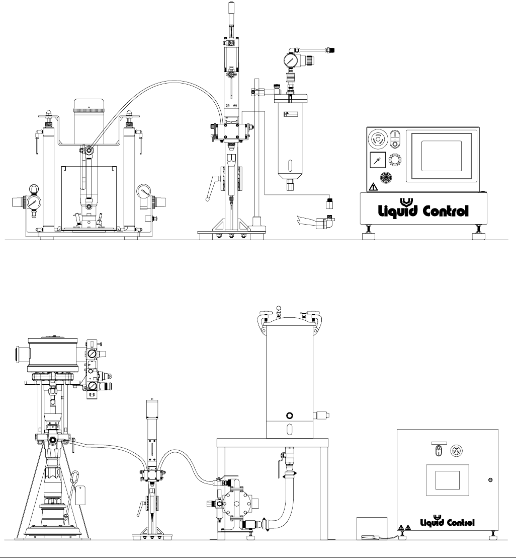
Typical System Configurations
FIG. 1
Liquid Control Corp.
NORTH CANTON, OH 44720 USA
8400 PORT JACKSON AVE. N.W.
NUMBER
SERIAL
NUMBER
MODEL
10 56 9078234
LOCK
PUSH TO
PULL TO
RELEASE
WARNING
removing air pressure and
waring saftey glasses.
Do Not service without
1
A Side Feed
Base Unit
B Side Feed
Controls
CONTROL POWER
Liquid Control Corp.
NORTH CANTON, OH 44720 USA
8400 PORT JACKSON AVE. N.W.
NUMBER
SERIAL
NUMBER
MODEL
A Side Feed
Base Unit
B Side Feed
Controls
Component Identification
16 313876F
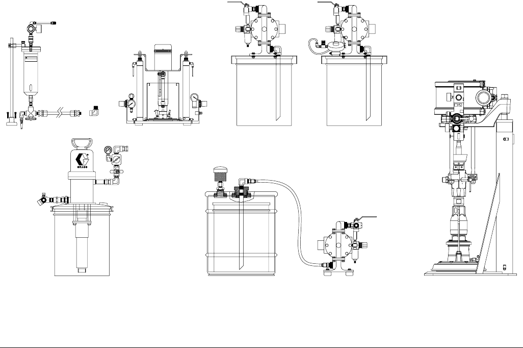
Typical Feed System Components
FIG. 2
DO NOT SERVICE WITHOUT
REMOVING AIR PRESSURE AND
WEARING SAFETY GLASSES.
WARNING
F
200
psi
0
20 oz Cartridge Feed
with Mounting Post
5 Gallon Pail Cover
with Diaphragm Pump
1 Gallon Ram
and Pump
5 Gallon Pail Cover
with Diaphragm
Pump and Agitator
5 Gallon Ram and
11:1 Transfer Pump
5 Gallon Pail Cover
with Diaphragm
Pump
5 Gallon Pail Cover
with 5:1 Transfer
Pump
Component Identification
313876F 17
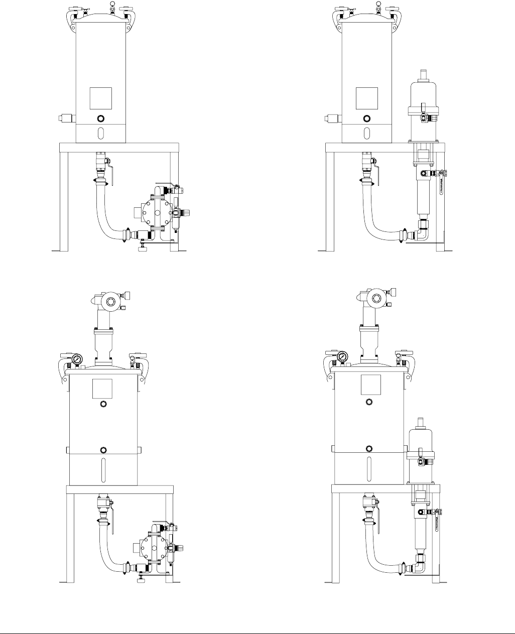
Typical Feed System Components (continued)
FIG. 3
R
0
12
8
4
psi
30
22
19
15
26
R
0
12
8
4
psi
30
22
19
15
26
5 Gallon Tank with Diaphragm Pump and Stand 5 Gallon Tank with 5:1 Pump and Stand
10 Gallon Tank with Diaphragm Pump, Agitator,
Vacuum, and Stand
10 Gallon Tank with 5:1 Pump, Agitator, Vacuum,
and Stand
Component Identification
18 313876F
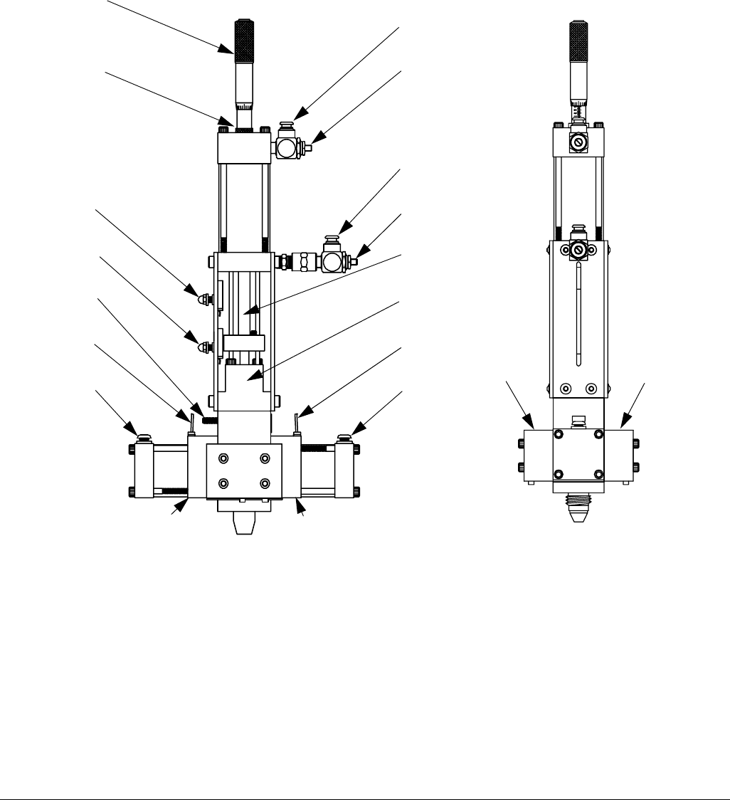
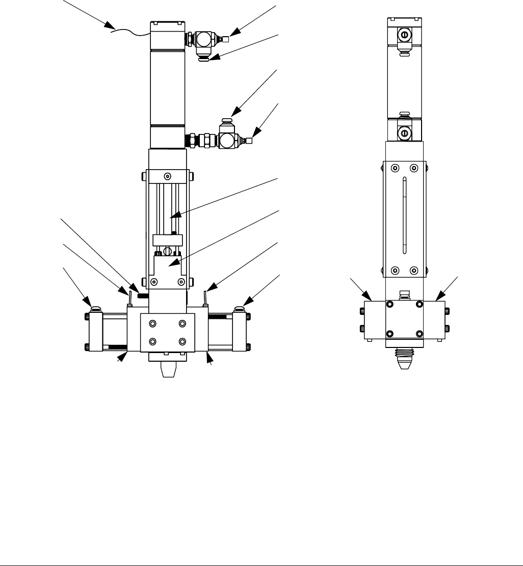
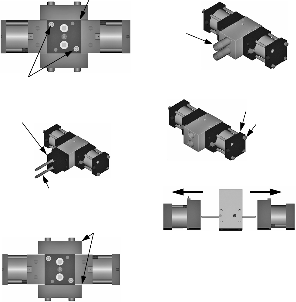
Micrometer PD44 Metering Valve
FIG. 4
Key:
A A Material Inlet
B B Material Inlet
C Grounding Lug
D Spool Assemblies
E Metering Rods
F Oil Cup Retaining Block
G Extend Air Inlet
H Retract Air Inlet
J Dispense Air Inlet
K Reload Air Inlet
L Extend Air Flow Adjustment
Knob
M Retract Air Flow Adjustment
Knob
N Retract Proximity Switch
P Extend Proximity Switch
R Spool Valve Proximity Switch
S Shot Size Locking Ring
T Shot Size Adjuster
T
S
P
C
R
G
H
E
N
R
A B
Side View Front View
KJ
F
DD
M
L
Component Identification
313876F 19
LRT PD44 Metering Valve
FIG. 5
B
A
Side View Front View
Key:
A A Material Inlet
B B Material Inlet
C Grounding Lug
D Spool Assemblies
E Metering Rods
F Oil Cup Retaining Block
G Extend Air Inlet
H Retract Air Inlet
J Dispense Air Inlet
K Reload Air Inlet
L Extend Air Flow Adjustment
Knob
M Retract Air Flow Adjustment
Knob
R Spool Valve Proximity Switch
U Transducer Connection
J
K
R
DD
C
R
E
F
H
M
L
G
U
Component Identification
20 313876F
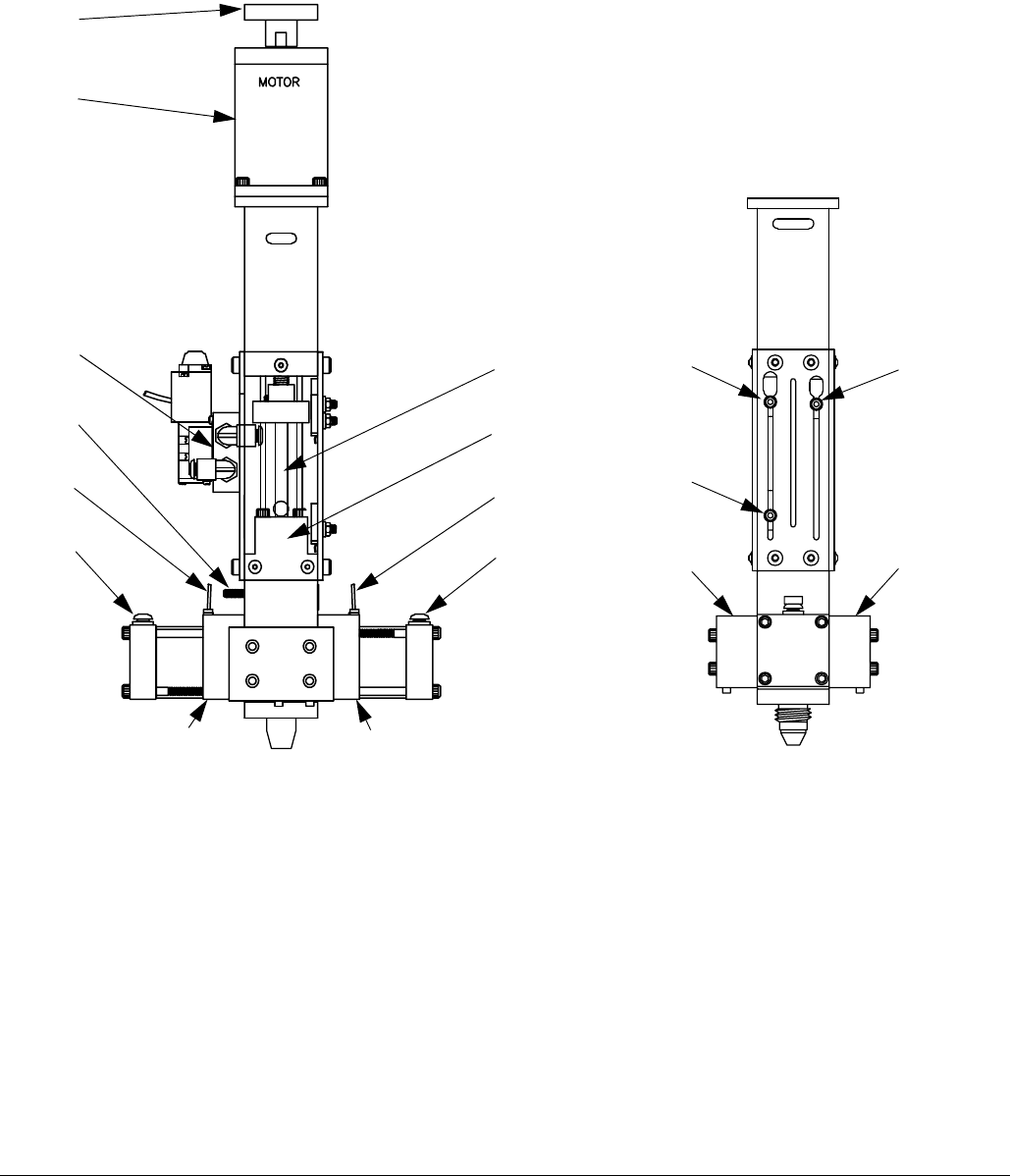
Motor Driven PD44 Metering Valve
FIG. 6
Side View Front View
Key:
A A Material Inlet
B B Material Inlet
C Grounding Lug
D Spool Assemblies
E Metering Rods
F Oil Cup Retaining Block
J Dispense Air Inlet
K Reload Air Inlet
L Extend Air Flow Adjustment
Knob
M Retract Air Flow Adjustment
Knob
N Over-travel Proximity Switch
P Home Proximity Switch
R Spool Valve Proximity Switch
V Optional Motor (provided with
configured controls)
W Over-travel Proximity Switch
X Main Air Inlet (on far side of
valve as shown)
R
E
J
F
C
R
K
DD
B
A
V
W
N
WP
X
Setup
313876F 21
Setup
NOTE: See Typical Installation diagram.
2.
1. Perform Setup procedure for feed system compo-
nents. See feed system manuals. See Related
Manuals on page 3.
2. Place an in-line air pressure regulator, air-water
separator/filter, and shut-off/bleed valve between
the air supply and the control solenoids.
3. Connect each 1/4 in. outside diameter supplied air
line to the corresponding control solenoid. See
Component Identification starting on page 15.
4. On the Motor Driven PD44, if a non-Graco motor is
used, install the motor onto the metering valve. See
Motor Mounting Diagram, page 23.
5. On the Motor Driven PD44, connect the required
electrical power to the metering valve. See Motor
Specifications, page 43.
6. Connect chemical lines from feed system to meter-
ing valve material inlets. See Component Identifi-
cation starting on page 15.
Typical Installation
FIG. 7
Metering Valve
A Side Pump
A Side Material Tank (optional)
A Side Fluid Shut-Off Valve
Air Supply Air Shut-off and Bleed Valve
B Side Pump B Side Fluid Shut-Off Valve
B Side Material Tank
Air Pressure Regulator
User Supplied
Air-Water Separator/Filter
Control Solenoids
Setup
22 313876F
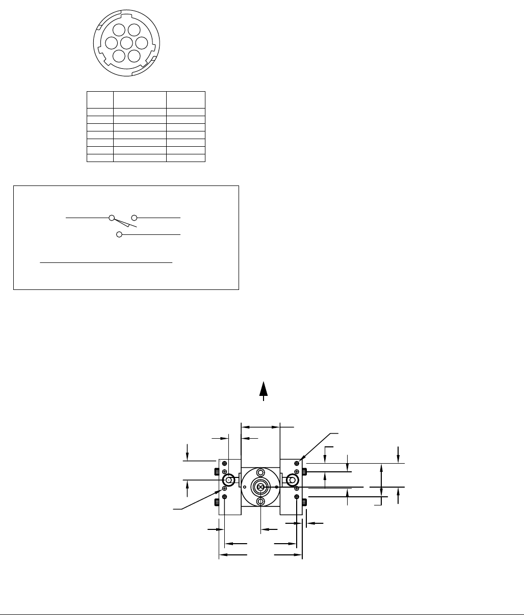
Tank Level Sensor Wiring
Schematic
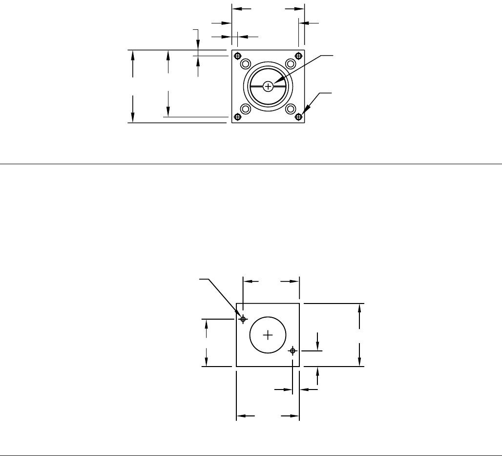
Valve Mounting Diagram
As desired, use the following diagram to mount the
metering valve.
TYPICAL LEVEL SENSOR WIRING
BLU
BLK
7
NUMBER PIN USAGE
4
5
6
2
3
PIN
1
TANK LEVEL
12
345
67
BROWN
BLACK
BLUE
BROWN
BLACK
BLUE
BLUE
24 VDC+ BRN
COM
SIGNAL
HIGH
LOW
LOW
LOW
LOW
HIGH
HIGH
USAGE
JUMPER PIN 6 AND 7
FIG. 8
1.63
3.75
3.25
0.563
4X Ø 0.188
DOWEL PINS
0.862
0.190
1.75
L
1.50
0.75 C
1.06
0.38
4X 10-24 X 0.5 DP
Bottom View
Front of Metering Valve
(Spool Assembly Not Shown)
Setup
313876F 23
Motor Mounting Diagram
If using a non-Graco motor with the Motor Driven PD44,
use the following diagram to install the non-Graco motor
onto the Motor Driven PD44 metering valve. See Motor
Specifications, page 43.
Custom Drive Mounting Diagram
If using a non-Graco lead screw or housing, use the fol-
lowing diagram to ensure that the guide rods will align
properly with the custom housing.
FIG. 9
2.22
2.22 2.039
0.182 2.039
0.182
Ø 0.251
STANDARD
4X 10-32
Top View of Drive Assembly
FIG. 10
Bottom View of Lead Screw Housing
2X #30 (0.129Ø)
FLAT BTTM DRILL X .25 DP
1.75
.44
1.31
.19
1.75
1.56
Startup
24 313876F
Startup
1. Lubricate the metering rod ports in the oil cup
retaining block and fill the spool valve ports with
compatible lubricant. Consult with your material
supplier to select an acceptable lubricant. Regularly
verify that lubricant is present.
2. Perform Ratio Check, page 26.
3. Install mixer and shroud.
4. Pressurize the A and B material feed systems con-
nected to the metering valve to prime the system.
See page 3 for maximum inlet feed pressures.
5. Dispense several full stroke shots until material is
air-free and has good shut-off at the nose.
NOTE: Very viscous, compressible materials may con-
tinue to droll after system is primed. Reduce flow rate as
required to produce air-free dispense.
NOTE: Very thin materials may require tilting the valve
greater than 45 degrees and dispensing shots until
material is air-free. Remove oil from cups before pro-
ceeding.
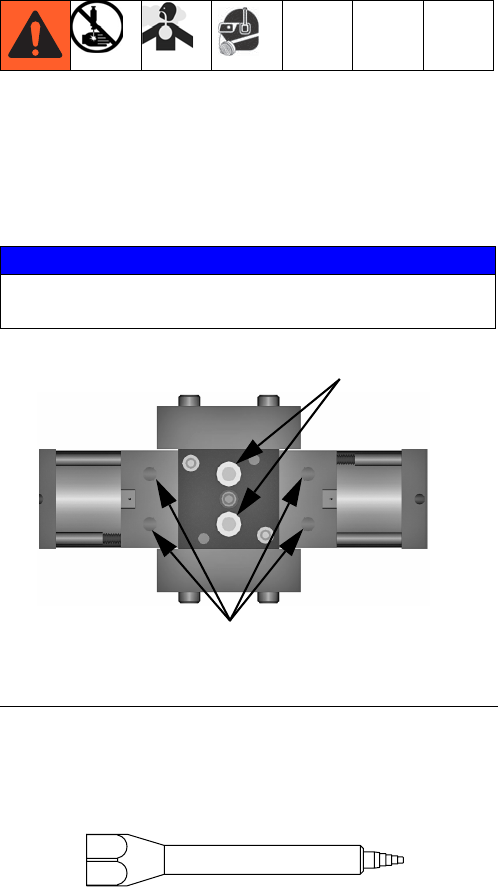
NOTICE
Testing has shown that failure to lubricate the valve
will significantly reduce seal life.
FIG. 11: Top View of Metering Valve with Top Section
Removed
Metering Rod Ports
Spool Valve Ports
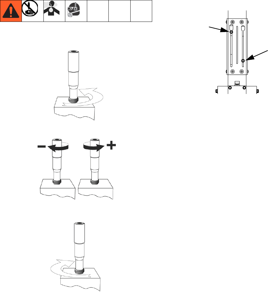
Adjusting the Shot Size
313876F 25
Adjusting the Shot Size
Micrometer PD44 Only
1. Rotate the shot size locking ring counterclockwise to
loosen.
2. Rotate the shot size adjuster to adjust shot size.
3. Rotate the shot size locking ring clockwise to
tighten.
4. Dispense into waste container to test shot size.
5. Repeat until desired shot size is achieved.
6. If LED on the extend proximity switch is not illu-
minated, slide the proximity switch until the LED on
the proximity switch is illuminated.
NOTE: The retract proximity switch (PX-RET) is factory
preset and does not need to be adjusted. If the lower
proximity switch is changed from the factory setting, see
the assembly drawings for more information on readjust-
ment. This switch is marked with a RET tag on the wire.
LRT and Motor Driven PD44
On LRT and Motor Driven PD44s, shot size is controlled
by the PD44 Control Box. See the PD44 Control Box
manual. See Related Manuals on page 3.
Extend
Proximity
Switch
Retract
Proximity
Switch
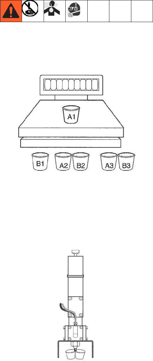
Ratio Check
26 313876F
Ratio Check
Perform ratio check procedure at startup and after
rebuild.
1. Weigh six small cups and label as indicated. Record
weights.
2. Remove mixer.
3. Install the ratio check nozzle.
4. Dispense into a waste container to prime the ratio
check nozzle.
5. Place cups as indicated under ratio check nozzle
and cycle machine once.
6. Repeat until all three sets of cups have been used.
7. Re-weigh all six cups and record weights.
8. Subtract weight of empty cups from weight of filled
cups to get material weights.
9. Complete ratio calculations.
Operation
313876F 27
Operation
The operation of the PD44 metering valve is controlled
by an external source. If a PD44 Control Box was pur-
chased, see the PD44 Control Box manual for operation
instructions. See Related Manuals on page 3.
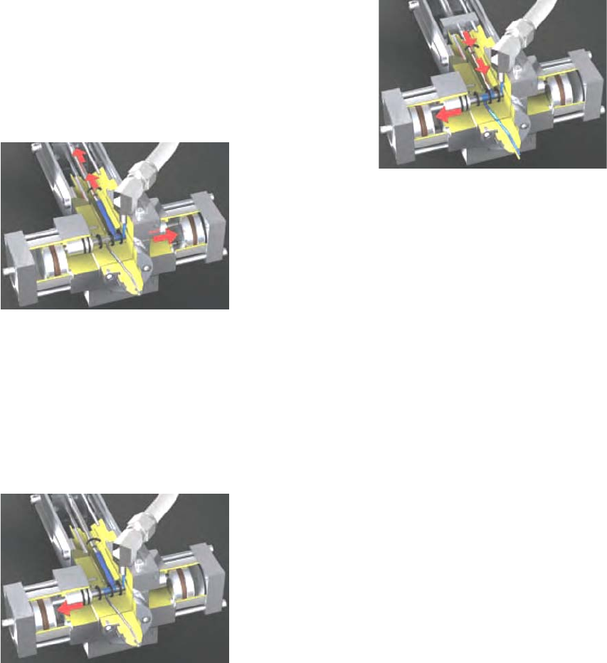
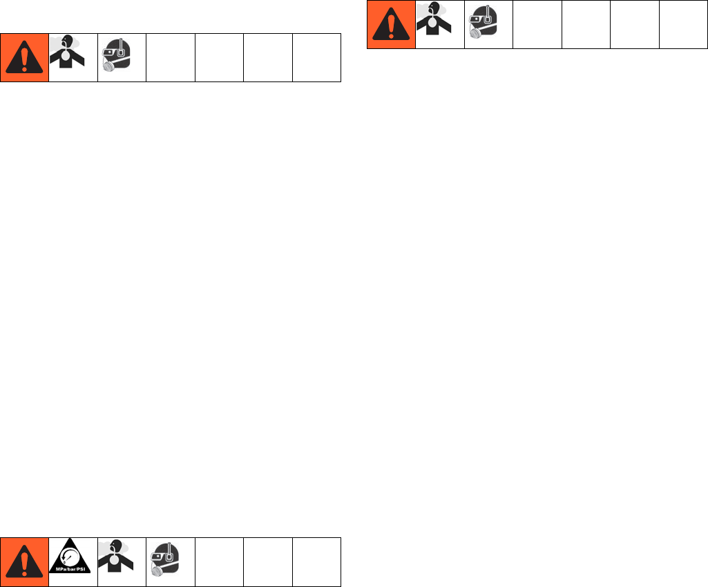
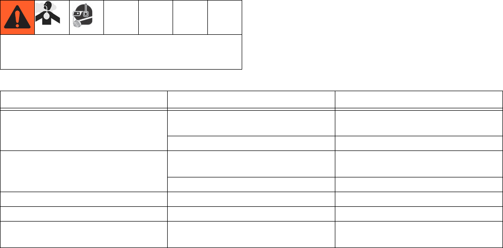
Sequence of Operation
Step 1: Reload
• Spools shift to the right
• Material feed inlets are opened
• Materials are transferred into the metering cham-
bers by a pressurized feed system
• Outlet ports are blocked
• Metering rods are retracted to a precise position
determining the volume of each material
Step 2: Shift
• The balanced spool assemblies shift to the dis-
pense position
• Material path to the mixer inlet is opened
• Material feed inlet ports are blocked
• Metering rods remain in the retracted position
Step 3: Dispense
• Metering rods extend
• A and B materials are simultaneously dispensed
from the metering chamber into the disposable
mixer
• A and B materials are dispensed at the predeter-
mined volume ratio.
Upon completion of the dispense stroke, the metering
rod and spool assemblies shift back to the reload posi-
tion.
Pressure Relief Procedure
28 313876F
Pressure Relief
Procedure
1. Retract the metering rods. See the PD44 Control
Box manual. See Related Manuals on page 3.
2. Close both the A side and B side fluid shut-off
valves.
3. Remove static mixer.
4. Dispense 5 shots. Shots should be at least 75% of
the full stroke.
5. Extend the metering rods into the tubes. If Graco
controls are provided with the system, see the PD44
Controls manual. See Related Manuals on page 3.
6. Close the incoming air shut-off/bleed valve that sup-
plies air to the metering valve.
7. Close the incoming air shut-off/bleed valve that sup-
plies the A feed system. Repeat for the B side feed
system. Refer to feed system manual for pressure
relief procedure. See Related Manuals on page 3.
Shutdown
1. Perform Pressure Relief Procedure.
2. Inspect the metering rods for material buildup.
Clean as necessary.
3. Lubricate the metering rods with compatible lubri-
cant such as mesamoll or silicone oil.
4. Install storage cap on outlet nose.
Maintenance
Perform the following procedures once a shift.
NOTE: If material is leaking, see Troubleshooting on
page 29.
Material Reservoirs
Check material levels and refill as necessary. Ensure
that the material reservoirs are properly vented.
Air Dryer
Check the condition of the desiccant air dryer. Replace
as necessary.
Metering Rod Ports
Lubricate with compatible lubricant such as mesamoll or
silicone oil. See FIG. 11 on page 24.
Spool Valve Ports
Fill with compatible lubricant such as mesamoll or sili-
cone oil. See FIG. 11 on page 24.
Ratio Check
See Ratio Check on page 26.
Troubleshooting
313876F 29
Troubleshooting
Schematics
For standard machines, the schematics will be
included in the PD44 Parts manual. See Related Manu-
als on page 3.
For custom machines, the schematics will be included
in the assembly drawings manual.
Perform Pressure Relief Procedure before perform-
ing any troubleshooting procedure.
Problem Cause Solution
Metering valve stalling and no mate-
rial being dispensed despite ade-
quate input pressure
Blocked mixer Check mixer for cured material,
replace mixer as required
Flow control valve closed Open
Metering valve not discharging nor-
mal or full volume
Low material level in reservoirs Fill material reservoirs and prime the
machine
Air in material tanks Fill reservoirs and prime machine
Material leaks past spool valves Spool valve worn or damaged Replace the spool valve and sleeve
Improper material mixing Mixer not clean or free Remove and replace the mixer
Material leaks around mixer while
dispensing
Cured material in mixer Check mixer for cured material,
replace mixer
Rebuild
30 313876F
Rebuild
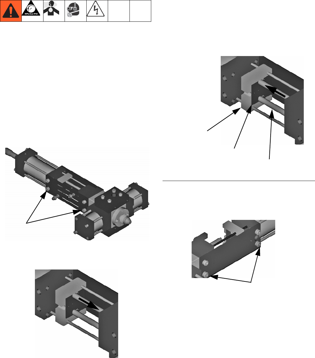
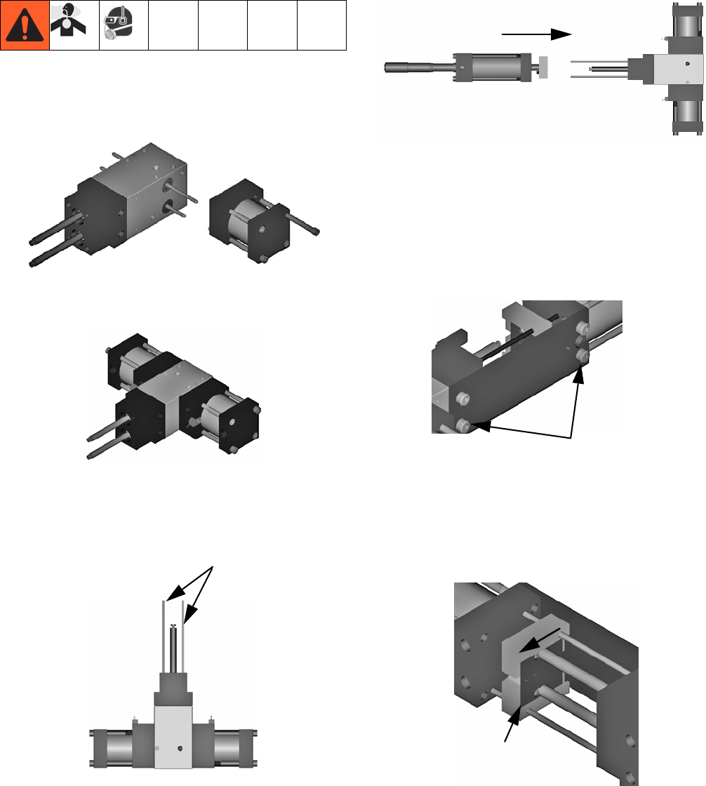
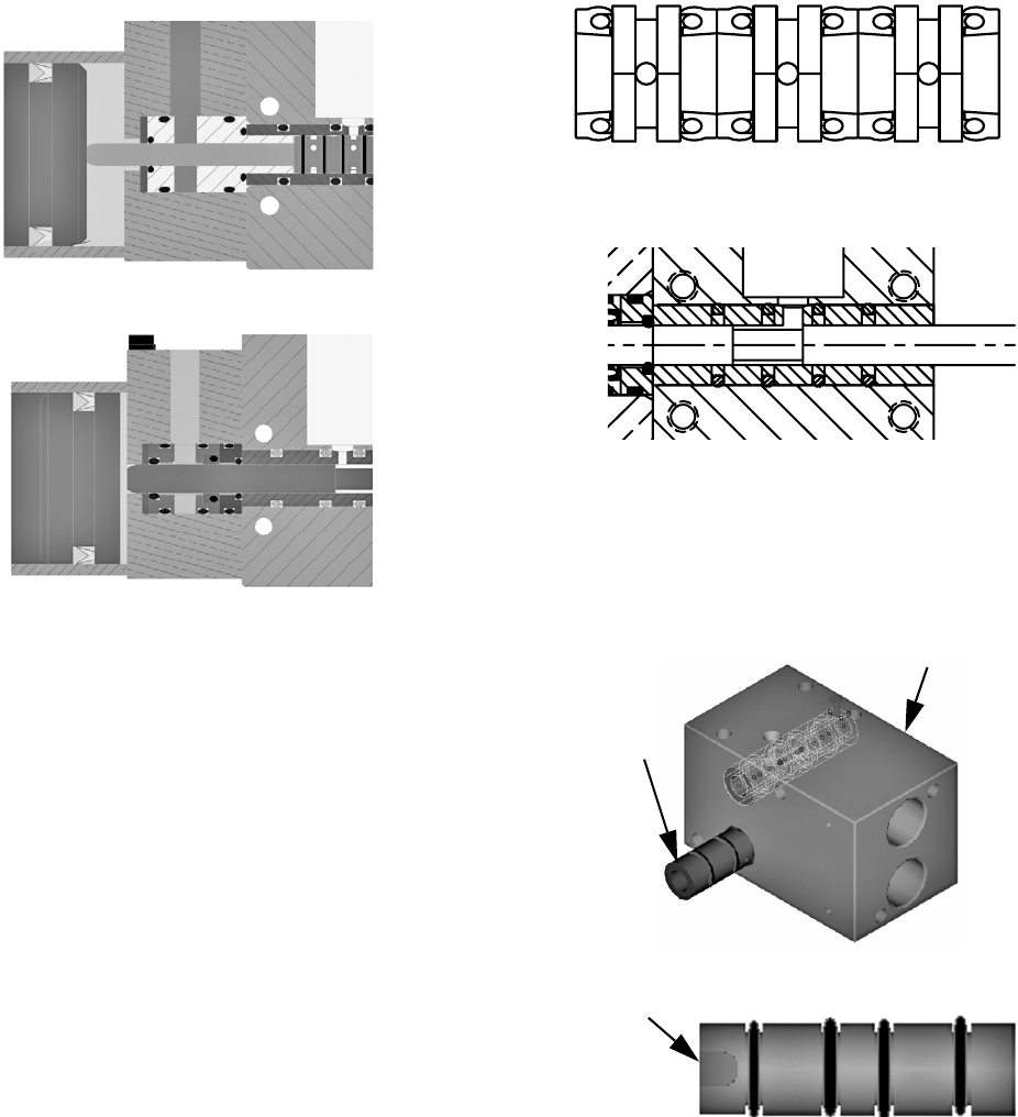
Wetted Section Disassembly
1. Perform Pressure Relief Procedure, page 28.
2. On Motor Driven PD44s, remove electrical power.
3. Mark and disconnect all material feed lines, pneu-
matic lines, and proximity switch wiring. Remove the
metering valve from mounts.
NOTE: On Micrometer and Motor Driven PD44s, the
rear tie plate is the tie plate with the proximity switches.
NOTE: On LRT PD44s, the rear tie plate is the tie plate
on the same side of the metering valve as the main air
inlets.
4. Remove the four cap screws to remove the rear tie
plate.
5. Manually move the connecting block down so that
rods are in the extended position.
6. Loosen set screws on top of the connecting block.
7. Slide the metering rod retaining plate until the larger
hole position is in-line with the metering rod. See
FIG. 12 in the following step.
8. Once the metering rod plate is in position, manually
move connecting block up. Rods will remain in posi-
tion and connecting block is separated from rods.
9. Once the metering rods are disconnected from the
retaining plate, remove the four cap screws from the
front tie plate.
10. Separate the drive cylinder and the valve guides
from the oil cup retaining block.
Cap Screws
FIG. 12
Connecting Block
Metering Rod Retaining Plate
Metering Rod
Cap Screws
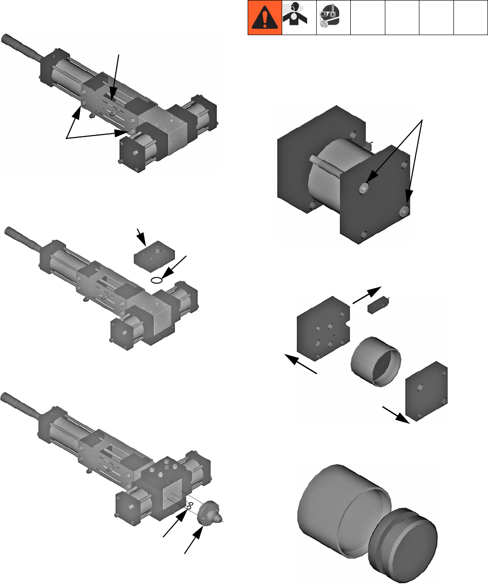
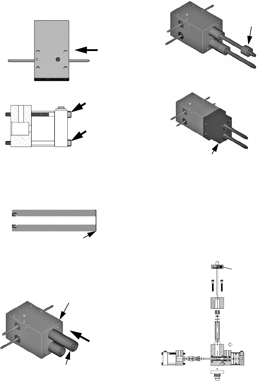
Rebuild
313876F 31
11. Remove the four cap screws located at the top of
the oil cup retaining block.
12. Remove the metering rods and oil cup retaining
block.
13. Remove the eight cap screws attaching the material
inlet blocks. Remove the material inlet blocks.
14. Remove the two metering rods and tubes. Always
keep rods and tubes together as they are a matched
set.
15. Remove the protruding cap screws on the each
spool block.
16. Remove the two pneumatic spools.
Cap Screws
Oil Cup Retaining Block
Metering Rod
Oil Cup Retaining Block
Material Inlet Blocks
Tu b e
Cap Screws
Spool Block
Rebuild
32 313876F
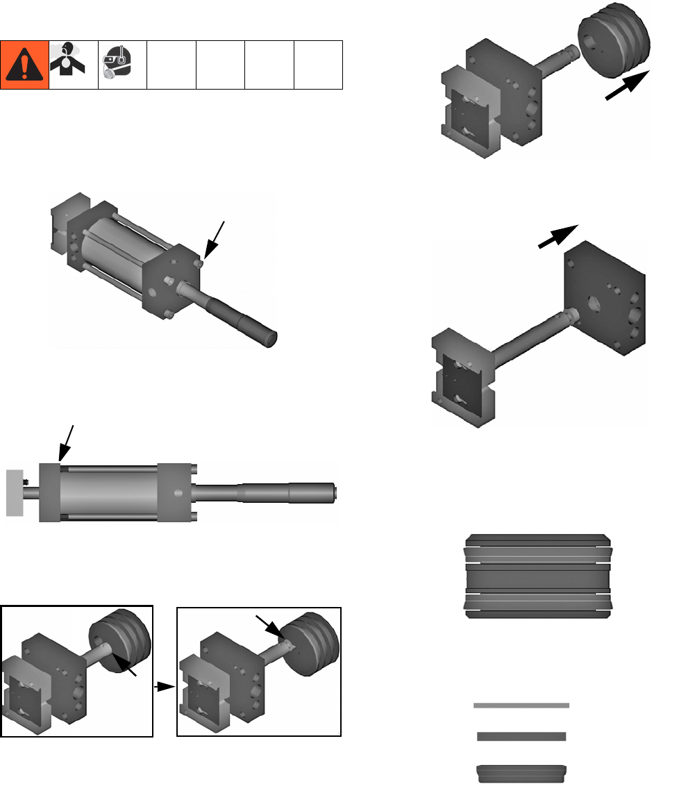
Wetted Section Reassembly
1. Install the pneumatic spool rod drive. Torque fasten-
ers to 67-70 in-lb (7.5-7.9 N•m).
2. Repeat for other side.
3. Install guide rods. Refer to Wetted Section Rebuild
on page 34 for details on spool valve and metering
rod assembly.
4. Install drive assembly to the guides.
5. Attach the front plate to the serial number side of the
metering body.
6. On Micrometer and LRT PD44s, ensure the air
inlet ports are pointed towards the front plate.
7. Install the cap head screws to the back plate.
8. Slide connecting block down until rod heads are
inserted into retaining plate keyway.
9. Slide the metering rod retaining plate to the locked
position.
10. Tighten set screw located on top of connecting block
until it contacts the top of the metering rod head.
Evenly torque the A and B set screws to 4-8 in-lb
(0.45-0.9 N•m).
Guide Rods
Micrometer PD44 shown
Cap Screws
Retaining Plate
Rebuild
313876F 33
11. Manually move connecting block up and down to
insure rods are properly installed.
12. Install the back plate and cap screws.
13. Install material inlet blocks with new o-rings.
14. Install material nose assembly with new o-rings.
15. Attach material line, pneumatic line, and electrical
harness.
16. Perform Startup procedure, page 24.
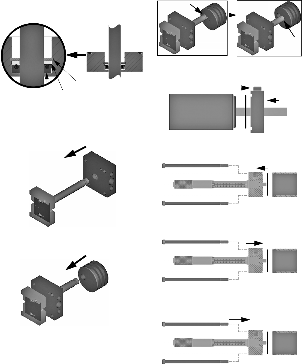
Spool Valve Rebuild
1. Perform Wetted Section Disassembly, page 30.
2. Remove the two cap screws.
3. Disassemble the spool cylinder.
4. Remove the piston from the cylinder.
5. Install new u-cup seal on piston.
Cap Screws
Back Plate
Material Inlet Block
O-Ring
O-Rings
Nose
Cap Screws
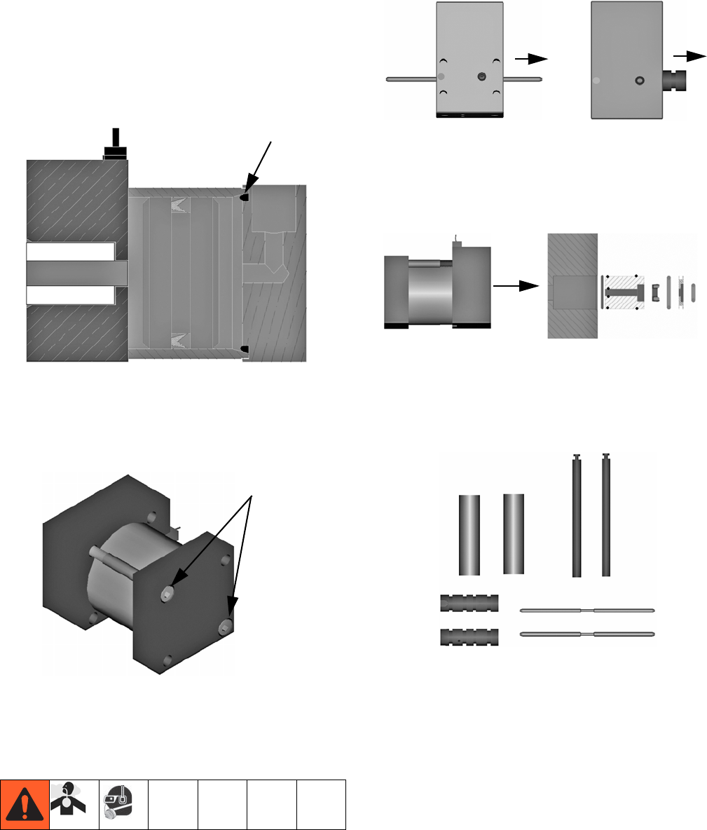
Rebuild
34 313876F
6. Insert new o-ring into spool air cylinder end cap.
7. Install proximity switch.
8. Apply Krytox or compatible lubricant to cylinder.
9. Insert piston into cylinder with the u-cup lip pointed
in the direction of the tapered end of the cylinder.
The “U” points toward the air inlet.
10. Careful not to cut the o-ring, install pneumatic spool
blocks.
11. Install the two cap screws.
12. Repeat for opposite side pneumatic spool rod drive.
Wetted Section Rebuild
1. Perform Wetted Section Disassembly, page 30.
2. Remove spool rods and sleeves from the metering
block.
NOTE: The spool sleeve can be removed by sliding the
sleeve in the direction of the identification marking.
3. Remove the pneumatic drive spool bearing, seals,
and seal retainer for both spools.
4. Inspect the metering rod and sleeve assemblies and
the spool rod and sleeve assemblies for excessive
wear. If there are any scratches on the rod that can
be felt by a fingernail, replace the rod and sleeve
assembly.
5. Clean all wetted components thoroughly with com-
patible solvent.
Air Inlet O-ring
Cap Screws
Rebuild
313876F 35
6. For each pneumatic drive spool block, install new
zap seals and o-rings onto o-ring retainer.
7. Lubricate o-rings and bearing surfaces with Krytox
or compatible lubricant.
8. Re-install the rod bearings, zap seals, and o-rings
retainers into each spool block.
NOTE: Typically, the spring in the zap seal and the
o-rings in the retainers point toward the metering block
which is in the direction of the material.
9. On each spool sleeve, install new zap seal (on low
viscosity spool), and o-rings on the outside of the
sleeves.
10. Lubricate o-rings and bearing surfaces with Krytox
or compatible lubricant.
NOTE: Correct orientation of seals shown.
11. Carefully install the spool sleeves into the metering
block. Make sure the notched edge will align with
the pin in the metering block and not cut the spool
sleeve o-rings.
Low Viscosity Spool
High Viscosity Spool
High Viscosity Spool Sleeve Cutout View
Low Viscosity Spool Sleeve Seals
Spool Sleeve
Metering Block
Spool Sleeve Notch
Rebuild
36 313876F
12. Apply Krytox to spool rod then carefully install the
spool rod into the spool sleeve (inside the metering
block). Make sure not to cut the spool sleeve zap
seals (on low viscosity spools).
13. Torque bolts 67-70 in-lb (7.6-7.9 N•m)
14. Install new zap seal in the metering tube sleeve with
the spring facing down or toward the material pres-
sure side of the sleeve.
NOTE: Seals are individually packaged with part num-
ber and size. Verify rod nominal size matches seal prior
to installation.
15. Install the metering sleeve PTFE seal in the meter-
ing block. Replace the metering sleeve PTFE seal
with a new one every rebuild.
16. Install metering tube sleeve into the metering block.
17. Install the wetcup sleeve onto the metering sleeve.
18. Install the oil cup retaining block. Torque to 77 in-lb
(8.7 N•m).
19. Apply Krytox grease to chamfer of metering rod.
20. Carefully insert metering rod through bearing, seal,
and metering tube. Make sure not to cut the meter-
ing sleeve zap seals.
21. Move connecting block to extended position.
22. Move slide plate to capture the metering rods.
23. Install the set screw until it contacts the top of the
metering rod. Torque set screw to 4-8 in-lb
(0.45-0.90 N•m).
Metering Sleeve PTFE Seal
Metering Tube Sleeve
Metering Block
Wetcup Sleeve
Oil Cup Retaining Block
Front
Set Screw
"A" Side
Rebuild
313876F 37
Micrometer Drive Rebuild
(Micrometer PD44 Only)
1. Perform Wetted Section Disassembly, page 30.
2. Remove the four cap screws located at the top of
the pneumatic drive assembly.
3. Remove the drive top cap.
4. Slide the drive rod into the open slot.
5. Slide the pneumatic drive piston off the drive rod.
6. Slide the air cylinder mounting block off the drive
rod.
7. Install new seals on the drive piston. Make sure the
lip of the seal points toward the pressure side of the
drive. See the following illustration and the assembly
drawings for more information.
8. Remove retaining ring, washer, and posipak seal
from the air cylinder mounting block.
Cap Screws
Drive Top Cap
Retaining Ring
Washer
Posipak Seal
Rebuild
38 313876F
9. Install new posipak seal with the o-ring pointed
towards the drive piston, then install washer and
retaining ring.
10. Apply Krytox or compatible lubricant to drive rod.
11. Careful not to cut the posipak seal, install drive rod
into the block.
12. Install the drive rod into the piston.
13. Slide the drive rod into the closed slot in the piston.
14. Install the cylinder o-ring then, careful not to cut the
piston seal, install the drive rod into the block.
15. Install the upper cylinder o-ring.
16. Install top cap block to cylinder.
17. Install drive housing bolts to the cylinder mounting
block.
Retaining Ring
Washer
Posipak Seal
Electrical Requirements
313876F 39
Electrical Requirements
Electrical requirements for pneumatically driven and
stepper driven control boxes can be found in the PD44
Control Box manual. See Related Manuals, page 3.
PD44 metering valve only: Wiring harness sensors are
24 VDC normally open PNP. See FIG. 13, FIG. 14, or
FIG. 15 as appropriate.
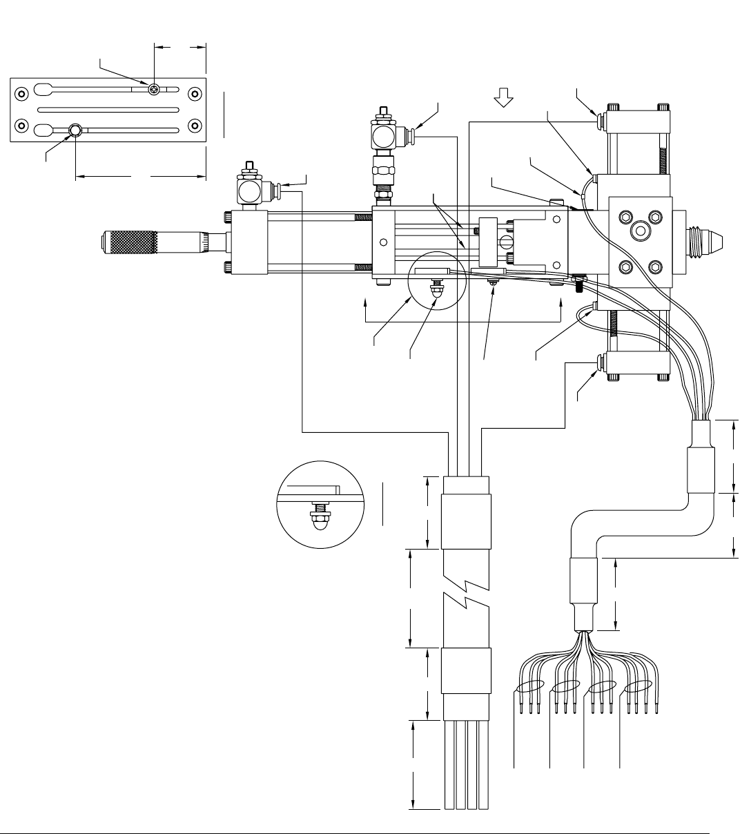
FIG. 13: Micrometer PD44 Metering Valve Electrical Requirements
FRONT
A
VIEW A-A
3-7/8
1-7/16
PX-EXT
PX-RET
USE SENSOR
HARDWARE
PX-OSV
(42.5")
PX-CSV
(39.5")
PX-RET
(41.5")
PX-EXT
(42")
YELLOW
GREEN
BLUE
RED
SEE DETAIL 1
DETAIL 1
RED EXTEND
6
BLUE RETRACT
YELLOW DISPENSE
GREEN RELOAD
22
25
2
230
BRN (24VDC+)
BLK (SIG)
BLU (DC COM)
LABEL PX-EXT
LABEL PX-RET
LABEL PX-CSV
LABEL PX-OSV
BLU (DC COM)
BLK (SIG)
BRN (24VDC+)
BRN (24VDC+)
BLK (SIG)
BLU (DC COM)
BRN (24VDC+)
BLK (SIG)
BLU (DC COM)
A
(48")
SOL-EXT
(45")
SOL-RET
(44")
SOL-OSV
(39")
SOL-CSV
WIRE
LABEL
TYP
GND
SERIAL
LEGEND
METERING
RODS
SEQUENCE OF OPERATION:
1. SPOOLS IN RELOAD POSITION
(SOL-CSV 'ON', PX-CSV 'ON')
2. METERING RODS IN HOME/RELOAD
POSITION (SOL-RET 'ON', PX-EXT 'ON')
3. START SIGNAL INITIATED
4. SPOOL SHIFT DISPENSE
(SOL-CSV 'OFF', SOL-OSV 'ON',
PX-OSV 'ON', PX-CSV 'OFF')
5. METERING RODS DISPENSE
(SOL-RET 'OFF', SOL-EXT 'ON')
6. METERING ROD REACH PX-RET SWITCH.
7. SPOOLS SHIFT RELOAD POSITION
(SOL-OSV 'OFF', SOL-CSV 'ON',
PX-OSV 'OFF', PX-CSV 'ON')
8. METERING RODS RETRACT
(SOL-EXT 'OFF', SOL-RET 'ON'
PX-OSV 'OFF', PX-CSV 'ON',
PX-EXT 'ON', PX-RET 'OFF')
I/O DEFINITION:
PX-EXT METERING RODS AT HOME OR
RELOAD POSITION (ADJUSTABLE).
PX-RET METERING RODS COMPLETED
DISPENSE STROKE (FIXED MOUNT).
PX-CSV SPOOL VALVE IN THE RELOAD
POSITION ALWAYS ON WHEN VALVE
IS NOT DISPENSING.
PX-OSV SPOOL VALVE IN THE DISPENSE
POSITION ON ONLY DURING
DISPENSE STROKE.
SOL-EXT AIR SIGNAL TO DRIVE METERING
RODS DOWN (DISPENSE) RED TUBE.
SOL-RET AIR SIGNAL TO RETRACT METERING
RODS (RELOAD) BLUE TUBE.
SOL-CSV AIR SIGNAL TO CLOSE SPOOL VALVE
(RELOAD POSITION) GREEN TUBE.
SOL-OSV AIR SIGNAL TO OPEN SPOOL VALVE
(DISPENSE READY POSITION) YELLOW TUBE.
Electrical Requirements
40 313876F
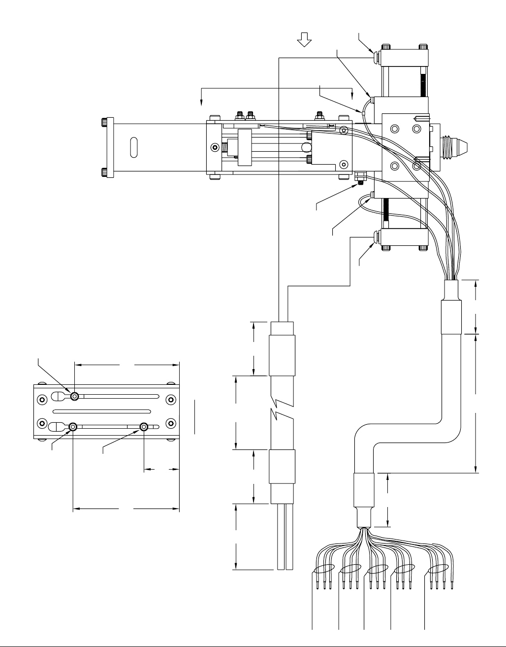
FIG. 14: Motor Driven PD44 Metering Valve Electrical Requirements
GROUND
STUD
PX-CSV
(39.5")
25"
2" 2"
6"
2"
YELLOW DISPENSE
GND
BLU (DC COM)
BLK (SIG)
LABEL PX-HOME
BRN (24VDC+)
BLU (DC COM)
BLK (SIG)
BLU (DC COM)
LABEL PX-OSV
LABEL PX-CSV
BRN (24VDC+)
BLU (DC COM)
BLK (SIG)
BRN (24VDC+)
LABEL PX-UP
LABEL PX-DOWN
BRN (24VDC+)
BLK (SIG)
BLU (DC COM)
BLK (SIG)
BRN (24VDC+)
GREEN RELOAD
30" 2"
GREEN
(39")
3 15/16
1 5/16
PX-DOWN
(45")
USE SENSOR
HARDWARE
PX-UP
(47")
USE SENSOR
HARDWARE
3 7/8
VIEW A-A
TYP
PX-HOME
(47")
USE SENSOR
HARDWARE
WIRE
LABEL
TYP PX-OSV
(42.5")
A
(44")
YELLOW
FRONT
3) PX-UP AND DOWN TO BE USED FOR OVER TRAVELS
2) FOR PX-UP AND PX-DOWN, USE SCREW PROVIDED WITH SENSORS
A
1) SENSORS ARE PNP NORMALLY OPEN
NOTES:
Electrical Requirements
313876F 41
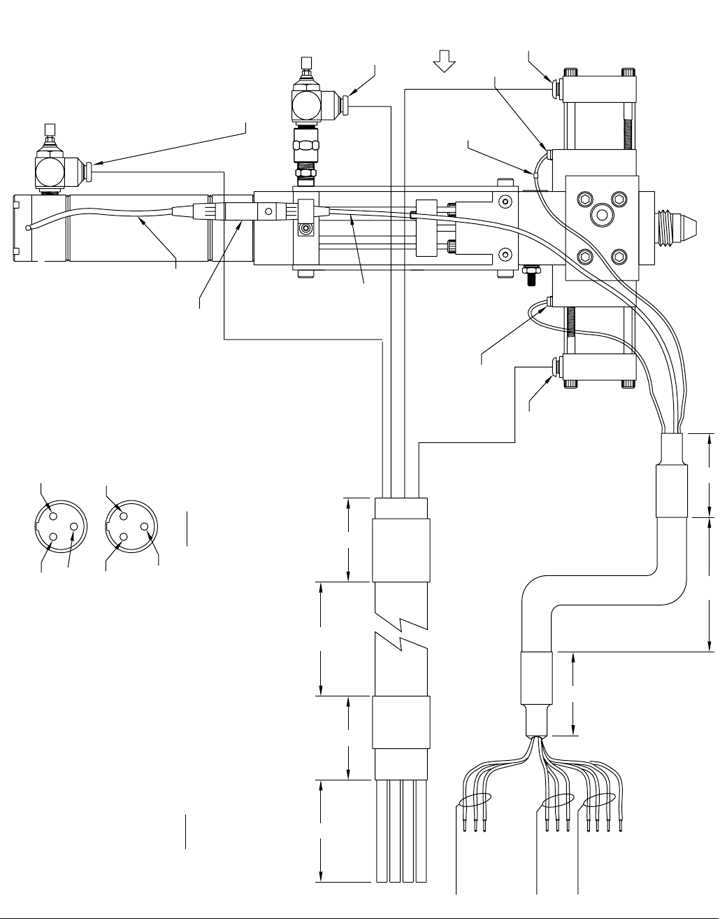
FIG. 15: LRT PD44 Metering Valve Electrical Requirements
FRONT
PX-OSV
(42.5")
PX-CSV
(39.5")
YELLOW
GREEN
BLUE
RED
RED EXTEND
6
BLUE RETRACT
YELLOW DISPENSE
GREEN DISPENSE
22
25
2
230
RED (OUTPUT)
BLK (-10VDC)
WHT (+10VDC)
LABEL LRT
LABEL PX-CSV
LABEL PX-OSV
BRN (24VDC+)
BLK (SIG)
BLU (DC COM)
BRN (24VDC+)
BLK (SIG)
BLU (DC COM)
(48")
(45")
(44")
(39")
WIRE
LABEL
TYP
NOTES:
LRT SIGNAL INPUT: 10 VDC TYPICAL
INPUT IMPEDANCE REQ:
SIGNAL OUTPUT:
THAN FS SIGNAL INPUT
SPEED:
1 MOhm
25 INCHES/SECOND
>0 TO SLIGHTLY LESS
GND
SEE 02/2980-4/25
3 WHT
1 BLK
LOOKING FROM SOLDER SIDE
2 RED
DETAIL 1
FEMALE
2 RED
1 BLK
3 WHT
MALE
PG-7
SEE
DETAIL 1
PG-7
F
M
(48")
Technical Data
42 313876F
Technical Data
NOTE: See feed system manuals for dimensions, weights, and wetted parts lists for those components. Dimensions,
weights, and wetted parts for components not covered in component feed system manuals and for combined assem-
blies are listed below.
* Sound data measured per standard ISO 11202 (1993) & ISO3746 (1995).
Maximum Ambient Temperature . . . . . . . . . . . . . . . . . . . 110°F (43°C)
Maximum Operating Temp . . . . . . . . . . . . . . . . . . . . . . . . 150°F (65°C)
Maximum Outlet Fluid Working Pressure. . . . . . . . . . . . . 2000 psi (14 MPa, 138 bar)
Maximum Air Working Pressure. . . . . . . . . . . . . . . . . . . . 100 psi (0.7 MPa, 7 bar)
Maximum Material Inlet Pressure. . . . . . . . . . . . . . . . . . . Metal Sleeves: 1200 psi (8 MPa, 83 bar)
Plastic Sleeves: 400 psi (2.8 MPa, 28 bar)
Supplied Air Requirements . . . . . . . . . . . . . . . . . . . . . . . 1 to 3 cfm at 80 psi to 100 psi
Ratio Range (depending on metering rods selected). . . . 1:1 to 25:1
Shot Size Range (depending on metering rods selected) 0.005 cc to 5.0 cc
Maximum Cycle Rate (application dependent) . . . . . . . . Micrometer PD44: Up to 60 cycles per minute
LRT PD44: Up to 60 cycles per minute
Motor Driven PD44: Up to 15 cycles per minute (with
standard Graco motor)
Dimensions (H x L x W), height to end of material inlet
block . . . . . . . . . . . . . . . . . . . . . . . . . . . . . . . . . . . . . . . . . Micrometer PD44: 17.5 x 4.13 x 7.57 in.
(445x105x192mm)
LRT PD44: 14.5 x 4.13 x 7.57 in. (368 x 105 x 192 mm)
Motor Driven PD44 (with Graco motor):
17.5 x 4.13 x 7.57 in. (445 x 105 x 192 mm)
Mixer: 4 - 14.75 in. (102 - 375 mm)
Graco-supplied Feed System Assemblies
(depends on selected options):
Smallest: 22.5 x 10 x 4 in. (572 x 254 x 102 mm)
Largest: 60 x 28 x 19 in. (1524 x 711 x 483 mm)
Weight . . . . . . . . . . . . . . . . . . . . . . . . . . . . . . . . . . . . . . . PD44 Metering Valve: 14 - 15 lb (6.35 - 6.80 kg)
Valve stand only: 8 lb (3.6 kg)
Feed Systems: 4 - 175 lb (1.8 - 79.4 kg)
Sound Data*. . . . . . . . . . . . . . . . . . . . . . . . . . . . . . . . . . . PD44 Metering Valve:
76.5 dBA Sound Power Level
92.8 dB Max Sound Pressure
Graco-supplied Feed Systems:
See Related Manuals, page 3.
Wetted Parts . . . . . . . . . . . . . . . . . . . . . . . . . . . . . . . . . . PD44 Metering Valve: Hardened steel, 303/304, 404,
UHMWPE, Tungsten, carbide, fluoroelastomer,
EPDM, PTFE
Graco-supplied Feed System Hoses and Fittings: Mild
steel, 303/304, PTFE, buna, polyethylene, polypropyl-
ene
Graco-supplied Tanks: Polyethylene, 303/304, mild steel
Technical Data
313876F 43
Motor Specifications
If a non-Graco motor is used with the Motor Driven
PD44 Metering Valve, it must meet the following specifi-
cations.
Frame: NEMA 23
Torque at Typical Dispense Speed: 180 oz-in.
(11.25 in-lb) at 10 revolutions per second (1/2 in. rod
travel per second) or less. Above 10 revolutions per sec-
ond, the power declines.
Torque at Maximum Speed: 117 oz-in (7.3 in-lb) at 20
revolutions per second (1 in. of rod travel per second).
Motor Face Pilot Boss: 1.5 in. diameter by 0.0625 in.
projection from motor face flange.
Shaft Size: 0.25 diameter by 0.75 in. projection from
motor face pilot boss to end of shaft.
All written and visual data contained in this document reflects the latest product information available at the time of publication.
Graco reserves the right to make changes at any time without notice.
Original instructions. This manual contains English. MM 313876
Graco Headquarters: Minneapolis
International Offices: Belgium, China, Japan, Korea
GRACO OHIO INC. 8400 PORT JACKSON AVE NW, NORTH CANTON, OH 44720
Copyright 2009, Graco Ohio Inc. is registered to ISO 9001
www.graco.com
Revised 07/2011
Graco Standard Warranty
Graco warrants all equipment referenced in this document which is manufactured by Graco and bearing its name to be free from defects in
material and workmanship on the date of sale to the original purchaser for use. With the exception of any special, extended, or limited warranty
published by Graco, Graco will, for a period of twelve months from the date of sale, repair or replace any part of the equipment determined by
Graco to be defective. This warranty applies only when the equipment is installed, operated and maintained in accordance with Graco’s written
recommendations.
This warranty does not cover, and Graco shall not be liable for general wear and tear, or any malfunction, damage or wear caused by faulty
installation, misapplication, abrasion, corrosion, inadequate or improper maintenance, negligence, accident, tampering, or substitution of
non-Graco component parts. Nor shall Graco be liable for malfunction, damage or wear caused by the incompatibility of Graco equipment with
structures, accessories, equipment or materials not supplied by Graco, or the improper design, manufacture, installation, operation or
maintenance of structures, accessories, equipment or materials not supplied by Graco.
This warranty is conditioned upon the prepaid return of the equipment claimed to be defective to an authorized Graco distributor for verification of
the claimed defect. If the claimed defect is verified, Graco will repair or replace free of charge any defective parts. The equipment will be returned
to the original purchaser transportation prepaid. If inspection of the equipment does not disclose any defect in material or workmanship, repairs will
be made at a reasonable charge, which charges may include the costs of parts, labor, and transportation.
THIS WARRANTY IS EXCLUSIVE, AND IS IN LIEU OF ANY OTHER WARRANTIES, EXPRESS OR IMPLIED, INCLUDING BUT NOT LIMITED
TO WARRANTY OF MERCHANTABILITY OR WARRANTY OF FITNESS FOR A PARTICULAR PURPOSE.
Graco’s sole obligation and buyer’s sole remedy for any breach of warranty shall be as set forth above. The buyer agrees that no other remedy
(including, but not limited to, incidental or consequential damages for lost profits, lost sales, injury to person or property, or any other incidental or
consequential loss) shall be available. Any action for breach of warranty must be brought within two (2) years of the date of sale.
GRACO MAKES NO WARRANTY, AND DISCLAIMS ALL IMPLIED WARRANTIES OF MERCHANTABILITY AND FITNESS FOR A
PARTICULAR PURPOSE, IN CONNECTION WITH ACCESSORIES, EQUIPMENT, MATERIALS OR COMPONENTS SOLD BUT NOT
MANUFACTURED BY GRACO. These items sold, but not manufactured by Graco (such as electric motors, switches, hose, etc.), are subject to
the warranty, if any, of their manufacturer. Graco will provide purchaser with reasonable assistance in making any claim for breach of these
warranties.
In no event will Graco be liable for indirect, incidental, special or consequential damages resulting from Graco supplying equipment hereunder, or
the furnishing, performance, or use of any products or other goods sold hereto, whether due to a breach of contract, breach of warranty, the
negligence of Graco, or otherwise.
FOR GRACO CANADA CUSTOMERS
The Parties acknowledge that they have required that the present document, as well as all documents, notices and legal proceedings entered into,
given or instituted pursuant hereto or relating directly or indirectly hereto, be drawn up in English. Les parties reconnaissent avoir convenu que la
rédaction du présente document sera en Anglais, ainsi que tous documents, avis et procédures judiciaires exécutés, donnés ou intentés, à la suite
de ou en rapport, directement ou indirectement, avec les procédures concernées.
Graco Information
For the latest information about Graco products, visit www.graco.com.
TO PLACE AN ORDER, contact your Graco distributor or call to identify the nearest distributor.
Toll Free: 1-800-746-1334 or Fax: 330-966-3006
