Graco 313998S Hfr Users Manual HFR, Repair Parts, English
2015-04-02
: Graco Graco-313998S-Hfr-Users-Manual-685869 graco-313998s-hfr-users-manual-685869 graco pdf
Open the PDF directly: View PDF ![]() .
.
Page Count: 94
- Related Manuals
- Models
- Product Configurator
- Whip Hose Bundles
- Individual B (Blue) Heated Whip Hose
- Individual A (Red) Heated Whip Hose
- B (Blue) Individual
- A (Red) Individual
- Hose Bundling Accessories
- Applicator
- B (Blue) Applicator Orifice
- Iso A (Red) Applicator Orifice
- AC Power Pack with S-Head/L-Head Hoses, Optional Boom
- Dispense Valve Interface Kit
- Flow Meters
- Pump Feed Kits
- B (Blue) and A (Red) Feed Tanks
- Warnings
- Important Two-Component Material Information
- A (Red) and B (Blue) Components
- Shutdown
- Pressure Relief Procedure
- Flushing
- Repair
- Parts
- Kits
- Logic Drawings
- Technical Data
- Motor Control Module Technical Data
- Graco Standard Warranty
- Graco Information
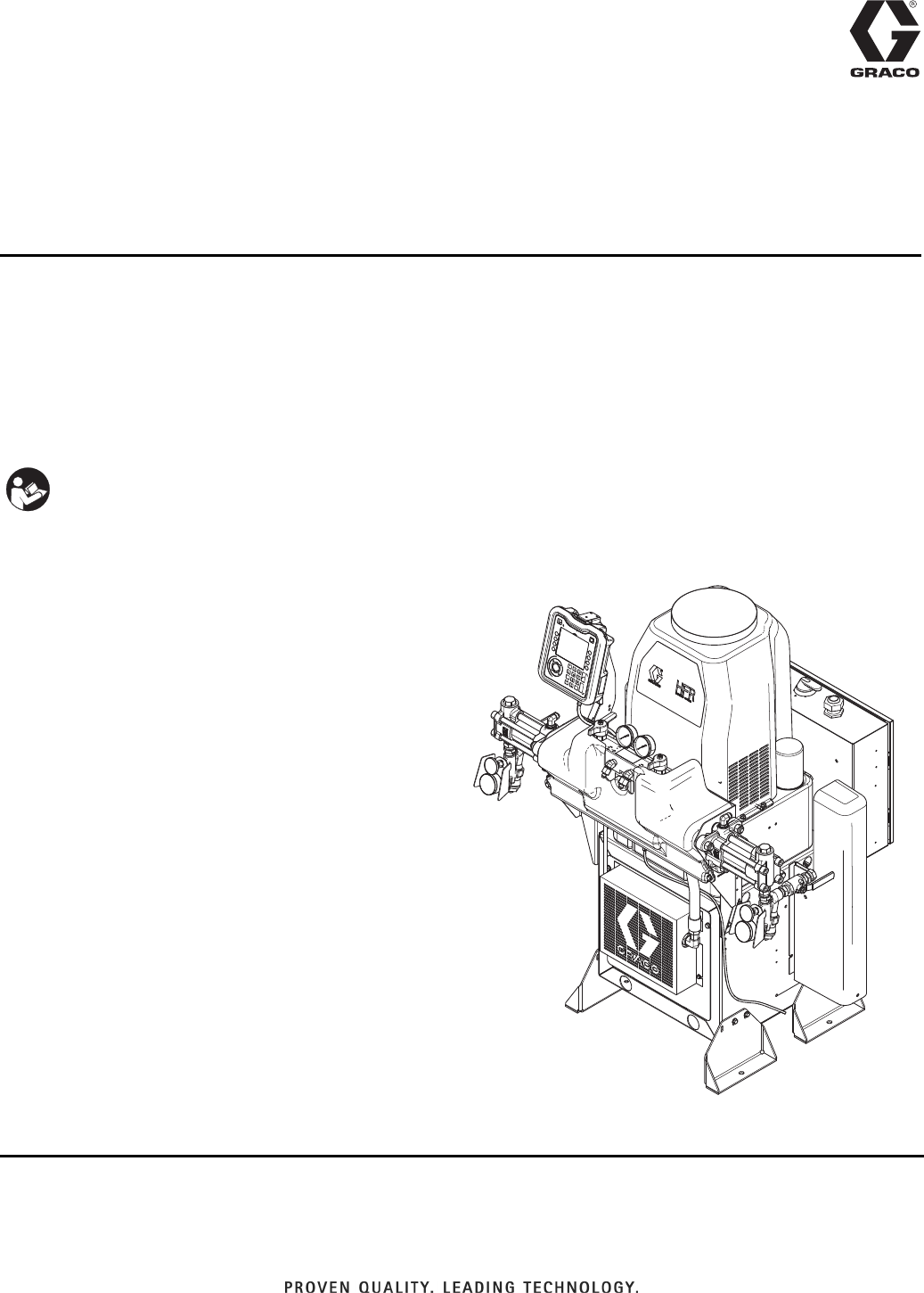
313998S
EN
Repair - Parts
HFR™
Hydraulic, Plural-Component, Fixed-Ratio Proportioner.
For pouring and dispensing sealants and adhesives and polyurethane foam.
For professional use only. Not for use in explosive atmospheres.
See page 4 for model information and maximum
working pressure.
Important Safety Instructions
Read all warnings and instructions in this
manual. Save these instructions.
ti19598a
2 313998S
Contents
Related Manuals ...........................3
Models ...................................4
Product Configurator .......................5
Whip Hose Bundles ......................7
Individual B (Blue) Heated Whip Hose ........7
Individual A (Red) Heated Whip Hose ........7
B (Blue) Individual ........................8
A (Red) Individual ........................9
Hose Bundling Accessories ...............10
Applicator .............................10
B (Blue) Applicator Orifice .................11
Iso A (Red) Applicator Orifice ..............12
AC Power Pack with S-Head/L-Head Hoses,
Optional Boom ......................13
Dispense Valve Interface Kit ...............13
Flow Meters ............................14
Pump Feed Kits .........................14
B (Blue) and A (Red) Feed Tanks ..........15
Warnings ................................17
Important Two-Component Material Information 19
Isocyanate Conditions ....................19
Material Self-ignition .....................19
Keep Components A (Red) and B (Blue) Separate
19
Moisture Sensitivity of Isocyanates ..........20
Foam Resins with 245 fa Blowing Agents .....20
Changing Materials ......................20
A (Red) and B (Blue) Components ............20
Shutdown ................................21
Pressure Relief Procedure .................. 22
Flushing .................................23
Repair ...................................24
Pumpline ..............................24
Hydraulic Power Pack Repair ..............32
Parts ....................................39
Base Machine ..........................39
Base Machine Sub-Assemblies ............47
Power Pack Module Sub-Assemblies ........54
Heater Options .........................57
Heater Sub-Assemblies ..................65
Kits .....................................72
DC Power Pack Pressure Adjustment Kit, 24C067
72
DC Power Pack Hydraulic Pressure Adjustment
Setup .............................73
Logic Drawings ...........................74
230V, 1 Phase, No Heat ..................74
230V, 1 Phase, with Heat .................75
230V, 3 Phase, No Heat ..................77
230V, 3 Phase, with Heat .................78
400V, 3 Phase, No Heat ..................80
400V, 3 Phase, with Heat .................81
A (Red) Heat ...........................83
B (Blue) Heat ...........................85
DC Hydraulic Power Pack .................87
Motor Control Module (MCM) ..............88
Miscellaneous Power ....................90
Technical Data ............................92
Motor Control Module Technical Data .........93
Graco Standard Warranty ...................94
Graco Information .........................94

Related Manuals
313998S 3
Related Manuals
Manuals are available at www.graco.com.
Component manuals in U.S. English:
System Manuals
313997 HFR Setup-Operation
Power Distribution Box Manual
3A0239 Power Distribution Boxes Instruc-
tions-Parts
Pumpline Manuals
3A0019 Z-Series Chemical Pumps Instruc-
tions-Parts
3A0020 HFR Hydraulic Actuator Instruc-
tions-Parts
Feed System Manuals
3A0238 Dispense Head Hydraulic Power
Pack Instructions-Parts
3A0235 Feed Supply Kits
Instructions-Parts
3A0395 Stainless Steel Tank Feed Sys-
tems Instructions-Parts
3A1299 Carbon Steel Tank Feed Systems
Instructions-Parts
309572 Heated Hose, Instructions-Parts
3A0237 Heated Hoses and Applicator Kits,
Instructions-Parts
Dispense Valve Manuals
313872 EP™Gun
313536 GX-16, Operation
312185 MD2 Valve, Instructions-Parts
312752 S-Head Operation-Parts
312753 L-Head Operation-Parts
309550 Fusion®AP Gun
309856 Fusion MP Gun
312666 Fusion CS Gun
Accessory Manuals
3A1149 HFR Discrete Gateway Module
Kits Manual

Models
4 313998S
Models
See Product Configurator on page 5 for detailed prod-
uct configuration information.
* Full load amps with all devices operating at maximum capabilities. Fuse requirements at various flow rates and
mix chamber sizes may be less.
** Values are dependent on installed pump size. Values shown are for largest available pump size.
†210 ft (64 m) maximum heated hose length, including whip hose.
◆Flow rate is independent of frequency 50/60 Hz.
★approved.
‡The maximum fluid working pressure for the base machine without hoses is 3000 psi (20.7 MPa, 207 bar). If
hoses rated at less than 3000 psi are installed, the system maximum fluid working pressure becomes the rating of
the hoses. If 2000 psi hoses were purchased and installed by Graco, the working pressure for the machine is
already setup for the lower 2000 psi (13.8 MPa, 138 bar) working pressure by Graco. If the machine was pur-
chased without hoses and aftermarket hoses rated at or above 3000 psi are to be installed, see Adjust Motor
Control Module Selector Switch on page 34 for the procedure to setup the machine for higher rated hoses. The
change in working pressure is made by changing a rotary switch setting in the Motor Control Module. The mini-
mum pressure rating for hoses is 2000 psi. Do not install hoses with a pressure rating lower than 2000 psi.
✖See 400 V Power Requirements.
400 V Power Requirements
• 400 V systems are intended for International voltage
requirements. Not for voltage requirements in North
America.
• If a 400 volt configuration is operated in North Amer-
ica, a special transformer rated for 400 V (“Y” con-
figuration (4 wire)) may be required.
• North America mostly employs a 3 wire or Delta
configuration. The two configurations are not inter-
changeable.
System
Full Load
Peak Amps
Per Phase*
Voltage
(phase)
System
Watts†
Primary
Heater Watts
(per heater)
Max Flow
Rate◆**
lb/min (kg/min)
Approximate
Output per
Cycle (A+B)**
gal. (liter)
Hydraulic
Pressure
Ratio**
Maximum
Fluid Working
Pressure ‡
psi (MPa, bar)
HFR,
Non-Heated
55 A 230V (1) 12,650
-- 50 (22.7) 0.084 1.9:1 3000
(20.7, 207)
29 A 230V (3) 11,340
55A★✖ 400V (3) 12,650
HFR,
Heated
116 A 230V (1) 26,680
6,000 50 (22.7) 0.084 1.9:1 3000
(20.7, 207)
73 A 230V (3) 28,600
75A★✖ 400V (3) 28,600

Product Configurator
313998S 5
Product Configurator
An example of the product configurator would be the following configurator code.
The following part number fields apply for the HFR part numbering configurator fields.
HFR-A------
Ref.: 1 2 3 4 5 6
Configurator Revision
Base
Voltage
B (Blue) Pump
A (Red) Pump
Primary/Hose Heat
High Volume/Low Volume
Hose Bundle Assembly
HFR - A - 1 - 6 - AM - AM - D - AG
Ref.: 1 2 3 4 5 6
Configurator Revision
Base
Voltage
B (Blue) Pump
A (Red) Pump
Primary/Hose Heat
High Volume/Low Volume
Ref. 1 Part Base Unit
1 HFR Base Unit, Carbon Steel
2 HFR Base Unit, Stainless Steel
Ref. 2 Part Voltage
1 230V, 1 phase;
No Heat
2 230V, 1 phase;
Maximum of Two 6 kW Primary Heater and One
Zone of Hose Heat
3 230V, 3 phase;
No Heat
4 230V, 3 phase;
Maximum of Two 6 kW Primary Heaters and Two
Zones of Hose Heat
5 400V, 3 phase;
No heat
6 400V, 3 phase;
Maximum of Two 6 kW Primary Heaters and Two
Zones of Hose Heat
Ref. 3 Part B (Blue) Pump †
AA L010S1 10 cc Stainless Steel
AB L015S1 15 cc Stainless Steel
AC L020S1 20 cc Stainless Steel
AD L025S1 25 cc Stainless Steel
AE L030S1 30 cc Stainless Steel
AF L040S1 40 cc Stainless Steel
AG L050S1 50 cc Stainless Steel
AH L060S1 60 cc Stainless Steel
AJ L080S1 80 cc Stainless Steel
AK L100S1 100 cc Stainless Steel
AL L120S1 120 cc Stainless Steel
AM L160S1 160 cc Stainless Steel
AN L005S1 5 cc Stainless Steel
AP L086S1 86 cc Stainless Steel
AQ L065S1 65 cc Stainless Steel
Ref. 4 Part A (Red) Pump †
Code, Part, and Description for Ref. 4 are the same as Ref. 3

Product Configurator
6 313998S
† Pump size listed is the combined volume dispensed
in one extending stroke and one retracting stroke.
Ref. 5 Part Primary/Hose Heat
A No Heat
B A (Red) and B (Blue) Primary Heaters
C A (Red) and B (Blue) Primary Heaters, One Zone
of Hose Heat
D A (Red) and B (Blue) Primary Heaters, A (Red)
and B (Blue) Hose Heat
E A (Red) and B (Blue) Hose Heat, Carbon Steel
F A (Red) and B (Blue) Hose Heat, Stainless Steel
G B (Blue) Primary Heaters, B (Blue) Hose Heat
Ref. 6 Part
B (Blue) Applicator Hose or High Volume/
Low Volume Hose Bundle Assembly
NN -- No Hose
AA 24D108 Dual Hose, 2:1, 1/4 x 3/8, 5 ft, Stainless Steel,
3500 psi
AB 24D109 Dual Hose, 2:1, 1/4 x 3/8, 10 ft, Stainless Steel,
3500 psi
AC 24D110 Dual Hose, 2:1, 1/4 x 3/8, 25 ft, Stainless Steel,
3500 psi
AD 24D111 Dual Hose, 2:1, 1/4 x 3/8, 50 ft, Stainless Steel,
3500 psi
AE 24D112 Dual Hose, 1:1, 3/8 x 3/8, 5 ft, Stainless Steel,
3500 psi
AF 24D113 Dual Hose, 1:1, 3/8 x 3/8, 10 ft, Stainless Steel,
3500 psi
AG 24D114 Dual Hose, 1:1, 3/8 x 3/8, 25 ft, Stainless Steel,
3500 psi
AH 24D115 Dual Hose, 1:1, 3/8 x 3/8, 50 ft, Stainless Steel,
3500 psi
BA 24D116 Dual Hose, 2:1, 1/4 x 3/8, 5 ft, Stainless Steel,
3500 psi
BB 24D117 Dual Hose, 2:1, 1/4 x 3/8, 10 ft, Carbon Steel,
3500 psi
BC 24D118 Dual Hose, 2:1, 1/4 x 3/8, 25 ft, Carbon Steel,
3500 psi
BD 24D119 Dual Hose, 2:1, 1/4 x 3/8, 50 ft, Carbon Steel,
3500 psi
BE 24D120 Dual Hose, 1:1, 3/8 x 3/8, 5 ft, Carbon Steel,
3500 psi
BF 24D121 Dual Hose, 1:1, 3/8 x 3/8, 10 ft, Carbon Steel,
3500 psi
BG 24D122 Dual Hose, 1:1, 3/8 x 3/8, 25 ft, Carbon Steel,
3500 psi
BH 24D123 Dual Hose, 1:1, 3/8 x 3/8, 50 ft, Carbon Steel,
3500 psi
CA 24E968 Single Hose, 1:1, 1/4 x 1/4, 10 ft, Carbon Steel,
2000 psi
CB 24E963 Single Hose, 1:1, 1/4 x 1/4, 25 ft, Carbon Steel,
2000 psi
CC 24E964 Single Hose, 1:1, 1/4 x 1/4, 50 ft, Carbon Steel,
2000 psi
CD 24D124 Single Hose, 2:1, 1/4 x 3/8, 25 ft, Carbon Steel,
2000 psi
CE 24D125 Single Hose, 2:1, 1/4 x 3/8, 50 ft, Carbon Steel,
2000 psi
CF 24E969 Single Hose, 1:1, 3/8 x 3/8, 10 ft, Carbon Steel,
2000 psi
CG 24D126 Single Hose, 1:1, 3/8 x 3/8, 25 ft, Carbon Steel,
2000 psi
CH 24D127 Single Hose, 1:1, 3/8 x 3/8, 50 ft, Carbon Steel,
2000 psi
CJ 24E965 Single Hose, 1:1, 1/2 x 1/2, 50 ft, Carbon Steel,
2000 psi
CK 24E966 Single Hose, 1:1, 1/4 x 1/4, 50 ft, Carbon Steel,
3500 psi
CL 24D129 Single Hose, 2:1, 1/4 x 3/8, 50 ft, Carbon Steel,
3500 psi
CM 24D131 Single Hose, 1:1, 3/8 x 3/8, 50 ft, Carbon Steel,
3500 psi
CN 24E967 Single Hose, 1:1, 1/2 x 1/2, 50 ft, Carbon Steel,
3500 psi

Product Configurator
313998S 7
Whip Hose Bundles
Individual B (Blue) Heated Whip
Hose
Individual A (Red) Heated Whip
Hose
Part Description
24H076 10 ft (3 m) long, 1/4 in. (6 mm) ID, Carbon Steel,
Single Zone
24H077 10 ft (3 m) long, 3/8 in. (10 mm) ID, Carbon Steel,
Single Zone
24H078 10 ft (3 m) long, 1/4 in. (6 mm) ID, Carbon Steel,
Dual Zone
24H079 10 ft (3 m) long, 3/8 in. (10 mm) ID, Carbon Steel,
Dual Zone
24H080 10 ft (3 m) long, 1/4 in. (6 mm) ID, Stainless Steel,
Single Zone
24H081 10 ft (3 m) long, 3/8 in. (10 mm) ID, Stainless
Steel, Single Zone
24H082 10 ft (3 m) long, 1/4 in. (6 mm) ID, Stainless Steel,
Dual Zone
24H083 10 ft (3 m) long, 3/8 in. (10 mm) ID, Stainless
Steel, Dual Zone
Part Description
24E950 10 ft (3 m) long, 1/4 in. (6 mm) ID, Carbon Steel,
Single Zone, 3500 psi
24E952 10 ft (3 m) long, 3/8 in. (10 mm) ID, Carbon Steel,
Single Zone, 3500 psi
24H086 10 ft (3 m) long, 1/4 in. (6 mm) ID, Carbon Steel,
Dual Zone, 3500 psi
24H088 10 ft (3 m) long, 3/8 in. (10 mm) ID, Carbon Steel,
Dual Zone, 3500 psi
24H090 10 ft (3 m) long, 1/4 in. (6 mm) ID, Stainless Steel,
Single Zone, 3500 psi
24H092 10 ft (3 m) long, 3/8 in. (10 mm) ID, Stainless
Steel, Single Zone, 3500 psi
24H094 10 ft (3 m) long, 1/4 in. (6 mm) ID, Stainless Steel,
Dual Zone, 3500 psi
24H096 10 ft (3 m) long, 3/8 in. (10 mm) ID, Stainless
Steel, Dual Zone, 3500 psi
24H225 5 ft (1.5 m) long, 1/4 in. (6 mm) ID, Carbon Steel,
Single Zone, 3500 psi
24H227 5 ft (1.5 m) long, 3/8 in. (10 mm) ID, Carbon
Steel, Single Zone, 3500 psi
24H229 5 ft (1.5 m) long, 1/4 in. (6 mm) ID, Carbon Steel,
Dual Zone, 3500 psi
24H231 5 ft (1.5 m) long, 3/8 in. (10 mm) ID, Carbon
Steel, Dual Zone, 3500 psi
24H233 5 ft (1.5 m) long, 1/4 in. (6 mm) ID, Stainless
Steel, Single Zone, 3500 psi
24H235 5 ft (1.5 m) long, 3/8 in. (10 mm) ID, Stainless
Steel, Single Zone, 3500 psi
24H237 5 ft (1.5 m) long, 1/4 in. (6 mm) ID, Stainless
Steel, Dual Zone, 3500 psi
24H239 5 ft (1.5 m) long, 3/8 in. (10 mm) ID, Stainless
Steel, Dual Zone, 3500 psi
Part Description
24E949 10 ft (3 m) long, 1/4 in. (6 mm) ID, Carbon Steel,
Single Zone, 3500 psi
24E951 10 ft (3 m) long, 3/8 in. (10 mm) ID, Carbon Steel,
Single Zone, 3500 psi
24H085 10 ft (3 m) long, 1/4 in. (6 mm) ID, Carbon Steel,
Dual Zone, 3500 psi
24H087 10 ft (3 m) long, 3/8 in. (10 mm) ID, Carbon Steel,
Dual Zone, 3500 psi
24H089 10 ft (3 m) long, 1/4 in. (6 mm) ID, Stainless Steel,
Single Zone, 3500 psi
24H091 10 ft (3 m) long, 3/8 in. (10 mm) ID, Stainless
Steel, Single Zone, 3500 psi
24H093 10 ft (3 m) long, 1/4 in. (6 mm) ID, Stainless Steel,
Dual Zone, 3500 psi
24H095 10 ft (3 m) long, 3/8 in. (10 mm) ID, Stainless
Steel, Dual Zone, 3500 psi
24H224 5 ft (1.5 m) long, 1/4 in. (6 mm) ID, Carbon Steel,
Single Zone, 3500 psi
24H226 5 ft (1.5 m) long, 3/8 in. (10 mm) ID, Carbon
Steel, Single Zone, 3500 psi
24H228 5 ft (1.5 m) long, 1/4 in. (6 mm) ID, Carbon Steel,
Dual Zone, 3500 psi
24H230 5 ft (1.5 m) long, 3/8 in. (10 mm) ID, Carbon
Steel, Dual Zone, 3500 psi
24H232 5 ft (1.5 m) long, 1/4 in. (6 mm) ID, Stainless
Steel, Single Zone, 3500 psi
24H234 5 ft (1.5 m) long, 3/8 in. (10 mm) ID, Stainless
Steel, Single Zone, 3500 psi
24H236 5 ft (1.5 m) long, 1/4 in. (6 mm) ID, Stainless
Steel, Dual Zone, 3500 psi
24H238 5 ft (1.5 m) long, 3/8 in. (10 mm) ID, Stainless
Steel, Dual Zone, 3500 psi

Product Configurator
8 313998S
Hoses
B (Blue) Individual
Part Description
24D111 Dual Hose, 2:1, 1/4 x 3/8, 50 ft, Stainless Steel,
3500 psi
24D115 Dual Hose, 1:1, 3/8 x 3/8, 50 ft, Stainless Steel,
3500 psi
24D119 Dual Hose, 2:1, 1/4 x 3/8, 50 ft, Carbon Steel,
3500 psi
24D123 Dual Hose, 1:1, 3/8 x 3/8, 50 ft, Carbon Steel,
3500 psi
24E964 Single Hose, 1:1, 1/4 x 1/4, 50 ft, Carbon Steel,
2000 psi
24D125 Single Hose, 2:1, 1/4 x 3/8, 50 ft, Carbon Steel,
2000 psi
24D127 Single Hose, 1:1, 3/8 x 3/8, 50 ft, Carbon Steel,
2000 psi
24E965 Single Hose, 1:1, 1/2 x 1/2, 50 ft, Carbon Steel,
2000 psi
24E966 Single Hose, 1:1, 1/4 x 1/4, 50 ft, Carbon Steel,
3500 psi
24D129 Single Hose, 2:1, 1/4 x 3/8, 50 ft, Carbon Steel,
3500 psi
24D131 Single Hose, 1:1, 3/8 x 3/8, 50 ft, Carbon Steel,
3500 psi
24E967 Single Hose, 1:1, 1/2 x 1/2, 50 ft, Carbon Steel,
3500 psi
Part Description
24E902 Heated Hose, 5 ft, 1/4, Carbon Steel, 3500 psi
24E904 Heated Hose, 10 ft, 1/4, Carbon Steel, 3500 psi
24E906 Heated Hose, 25 ft, 1/4, Carbon Steel, 3500 psi
24E908 Heated Hose, 50 ft, 1/4, Carbon Steel, 3500 psi
24E910 Heated Hose, 5 ft, 3/8, Carbon Steel, 3500 psi
24E912 Heated Hose, 10 ft, 3/8, Carbon Steel, 3500 psi
24E914 Heated Hose, 25 ft, 3/8, Carbon Steel, 3500 psi
24E916 Heated Hose, 50 ft, 3/8, Carbon Steel, 3500 psi
24E918 Heated Hose, 5 ft, 1/2, Carbon Steel, 3500 psi
24E920 Heated Hose, 10 ft, 1/2, Carbon Steel, 3500 psi
24E922 Heated Hose, 25 ft, 1/2, Carbon Steel, 3500 psi
24E924 Heated Hose, 50 ft, 1/2, Carbon Steel, 3500 psi
24E926 Heated Hose, 5 ft, 1/4, Stainless Steel, 3500 psi
24E928 Heated Hose, 10 ft, 1/4, Stainless Steel, 3500 psi
24E930 Heated Hose, 25 ft, 1/4, Stainless Steel, 3500 psi
24E932 Heated Hose, 50 ft, 1/4, Stainless Steel, 3500 psi
24E934 Heated Hose, 5 ft, 3/8, Stainless Steel, 3500 psi
24E936 Heated Hose, 10 ft, 3/8, Stainless Steel, 3500 psi
24E938 Heated Hose, 25 ft, 3/8, Stainless Steel, 3500 psi
24E940 Heated Hose, 50 ft, 3/8, Stainless Steel, 3500 psi
24E942 Heated Hose, 5 ft, 1/2, Stainless Steel, 3500 psi
24E944 Heated Hose, 10 ft, 1/2, Stainless Steel, 3500 psi
24E946 Heated Hose, 25 ft, 1/2, Stainless Steel, 3500 psi
24E948 Heated Hose, 50 ft, 1/2, Stainless Steel, 3500 psi
262174 Unheated Hose, 5 ft, 1/4, Carbon Steel, 3500 psi
262176 Unheated Hose, 10 ft, 1/4, Carbon Steel,
3500 psi
262178 Unheated Hose, 25 ft, 1/4, Carbon Steel,
3500 psi
262180 Unheated Hose, 50 ft, 1/4, Carbon Steel,
3500 psi
262182 Unheated Hose, 5 ft, 3/8, Carbon Steel, 3500 psi
262184 Unheated Hose, 10 ft, 3/8, Carbon Steel,
3500 psi
262186 Unheated Hose, 25 ft, 3/8, Carbon Steel,
3500 psi
262188 Unheated Hose, 50 ft, 3/8, Carbon Steel,
3500 psi
262190 Unheated Hose, 5 ft, 1/2, Carbon Steel, 3500 psi
262192 Unheated Hose, 10 ft, 1/2, Carbon Steel,
3500 psi
262194 Unheated Hose, 25 ft, 1/2, Carbon Steel,
3500 psi
262196 Unheated Hose, 50 ft, 1/2, Carbon Steel,
3500 psi
262237 Unheated Hose, 5 ft, 1/4, Stainless Steel,
3500 psi
262239 Unheated Hose, 10 ft, 1/4, Stainless Steel,
3500 psi
262241 Unheated Hose, 25 ft, 1/4, Stainless Steel,
3500 psi
262243 Unheated Hose, 50 ft, 1/4, Stainless Steel,
3500 psi
262245 Unheated Hose, 5 ft, 3/8, Stainless Steel,
3500 psi
262247 Unheated Hose, 10 ft, 3/8, Stainless Steel,
3500 psi
262249 Unheated Hose, 25 ft, 3/8, Stainless Steel,
3500 psi
262251 Unheated Hose, 50 ft, 3/8, Stainless Steel,
3500 psi
262253 Unheated Hose, 5 ft, 3/8, Stainless Steel,
3500 psi
262255 Unheated Hose, 10 ft, 3/8, Stainless Steel,
3500 psi
262257 Unheated Hose, 25 ft, 3/8, Stainless Steel,
3500 psi
262259 Unheated Hose, 50 ft, 3/8, Stainless Steel,
3500 psi

Product Configurator
313998S 9
A (Red) Individual
Part Description
24E901 Heated Hose, 5 ft, 1/4, Carbon Steel, 3500 psi
24E903 Heated Hose, 10 ft, 1/4, Carbon Steel, 3500 psi
24E905 Heated Hose, 25 ft, 1/4, Carbon Steel, 3500 psi
24E907 Heated Hose, 50 ft, 1/4, Carbon Steel, 3500 psi
24E909 Heated Hose, 5 ft, 3/8, Carbon Steel, 3500 psi
24E911 Heated Hose, 10 ft, 3/8, Carbon Steel, 3500 psi
24E913 Heated Hose, 25 ft, 3/8, Carbon Steel, 3500 psi
24E915 Heated Hose, 50 ft, 3/8, Carbon Steel, 3500 psi
24E917 Heated Hose, 5 ft, 1/2, Carbon Steel, 3500 psi
24E919 Heated Hose, 10 ft, 1/2, Carbon Steel, 3500 psi
24E921 Heated Hose, 25 ft, 1/2, Carbon Steel, 3500 psi
24E923 Heated Hose, 50 ft, 1/2, Carbon Steel, 3500 psi
24E925 Heated Hose, 5 ft, 1/4, Stainless Steel, 3500 psi
24E927 Heated Hose, 10 ft, 1/4, Stainless Steel, 3500 psi
24E929 Heated Hose, 25 ft, 1/4, Stainless Steel, 3500 psi
24E931 Heated Hose, 50 ft, 1/4, Stainless Steel, 3500 psi
24E933 Heated Hose, 5 ft, 3/8, Stainless Steel, 3500 psi
24E935 Heated Hose, 10 ft, 3/8, Stainless Steel, 3500 psi
24E937 Heated Hose, 25 ft, 3/8, Stainless Steel, 3500 psi
24E939 Heated Hose, 50 ft, 3/8, Stainless Steel, 3500 psi
24E941 Heated Hose, 5 ft, 1/2, Stainless Steel, 3500 psi
24E943 Heated Hose, 10 ft, 1/2, Stainless Steel, 3500 psi
24E945 Heated Hose, 25 ft, 1/2, Stainless Steel, 3500 psi
24E947 Heated Hose, 50 ft, 1/2, Stainless Steel, 3500 psi
262173 Unheated Hose, 5 ft, 1/4, Carbon Steel, 3500 psi
262175 Unheated Hose, 10 ft, 1/4, Carbon Steel,
3500 psi
262177 Unheated Hose, 25 ft, 1/4, Carbon Steel,
3500 psi
262179 Unheated Hose, 50 ft, 1/4, Carbon Steel,
3500 psi
262181 Unheated Hose, 5 ft, 3/8, Carbon Steel, 3500 psi
262183 Unheated Hose, 10 ft, 3/8, Carbon Steel,
3500 psi
262185 Unheated Hose, 25 ft, 3/8, Carbon Steel,
3500 psi
262187 Unheated Hose, 50 ft, 3/8, Carbon Steel,
3500 psi
262189 Unheated Hose, 5 ft, 1/2, Carbon Steel, 3500 psi
262191 Unheated Hose, 10 ft, 1/2, Carbon Steel,
3500 psi
262193 Unheated Hose, 25 ft, 1/2, Carbon Steel,
3500 psi
262195 Unheated Hose, 50 ft, 1/2, Carbon Steel,
3500 psi
262236 Unheated Hose, 5 ft, 1/4, Stainless Steel,
3500 psi
262238 Unheated Hose, 10 ft, 1/4, Stainless Steel,
3500 psi
262240 Unheated Hose, 25 ft, 1/4, Stainless Steel,
3500 psi
262242 Unheated Hose, 50 ft, 1/4, Stainless Steel,
3500 psi
262244 Unheated Hose, 5 ft, 3/8, Stainless Steel,
3500 psi
262246 Unheated Hose, 10 ft, 3/8, Stainless Steel,
3500 psi
262248 Unheated Hose, 25 ft, 3/8, Stainless Steel,
3500 psi
262250 Unheated Hose, 50 ft, 3/8, Stainless Steel,
3500 psi
262252 Unheated Hose, 5 ft, 1/2, Stainless Steel,
3500 psi
262254 Unheated Hose, 10 ft, 1/2, Stainless Steel,
3500 psi
262256 Unheated Hose, 25 ft, 1/2, Stainless Steel,
3500 psi
262258 Unheated Hose, 50 ft, 1/2, Stainless Steel,
3500 psi

Product Configurator
10 313998S
Hose Bundling Accessories
Applicator
NOTE: When selecting an applicator, if an applicator is
chosen which does not have a signal communicating to
the HFR, then the sizes of the A and B pumps added
together must be greater or equal to 120 cc. For exam-
ple: A (red) pump size = 20 cc, B (blue) pump size = 100
cc, 20 cc + 100 cc = 120 cc. Since the pump sizes com-
bined = 120 cc, an applicator may be selected which
does not have a signal communicating to the HFR.
Part Description
24E953 Air Hose, 5 ft
15B280 Air Hose, 10 ft
15C624 Air Hose, 25 ft
15B295 Air Hose, 50 ft
24E900 Signal Cable, 5 pin, Male/Female, 2.0 meter
24E899 Signal Cable, 5 pin, Male/Female, 4.0 meter
24E898 Signal Cable, 5 pin, Male/Female, 8.5 meter
24E897 Signal Cable, 5 pin, Male/Female, 16.0 meter
24E896 Fluid Temperature Sensor Cable, 4 pin,
Male/Female, 2.0 meter
24E895 Fluid Temperature Sensor Cable, 4 pin,
Male/Female, 3.0 meter
24E894 Fluid Temperature Sensor Cable, 4 pin,
Male/Female, 8.0 meter
24E893 Fluid Temperature Sensor Cable, 4 pin,
Male/Female, 15.7 meter
24E954 Scuff Guard, 1.75 in. (44 mm), 200 ft (61 m) Roll
24E961 Scuff Guard, 1.75 in. (44 mm), 200 ft (61 m) Roll
261821 Wire Connector, 6AWG (4.11 mm)
24E955 Hose Lacing, 1500 ft (457.2 m) Roll
15B679 Hose Safety Label
Part Description
24A084 L-Head 6/10 With Calibration Orifice
24A085 L-Head 10/14 With Calibration Orifice
24A086 L-Head 13/20 With Calibration Orifice
24A090 S-Head 6-625 With Calibration Orifice
24A092 S-Head 6-500 L/S With Calibration Orifice
24A093 S-Head 6-625 L/S With Calibration Orifice
24J187 GX-16, 24:1, Straight, Machine Mount
24K233 GX-16, 24:1, Left, Machine Mount
24K234 GX-16, No Orifice, Left, Machine Mount
24E876 GX-16, No Orifice, Straight, Machine Mount
24E877 GX-16, 24:1, Right, Machine Mount
24E878 GX-16, No Orifice, Right, Machine Mount
CS00RD Fusion CS, 1:1 Only, 0.029
CS01RD Fusion CS, 1:1 Only, 0.042
CS02RD Fusion CS, 1:1 Only, 0.052
246100 Fusion AP, 1:1 Only, 0.029
247007 Fusion MP, 1:1 Only, 0.029
246101 Fusion AP, 1:1 Only, 0.042
247019 Fusion MP, 1:1 Only, 0.047
246102 Fusion AP, 1:1 Only, 0.052
247025 Fusion MP, 1:1 Only, 0.057
24D500 Applicator, MD2, 1:1, Soft, Carbon Steel
24D501 Applicator, MD2, 1:1, Soft, Carbon Steel, Electric
24D502 Applicator, MD2, 1:1, Soft, Carbon Steel, Lever
24D503 Applicator, MD2, 1:1, Soft, Stainless Steel
24D504 Applicator, MD2, 1:1, Soft, Stainless Steel, Elec-
tric
24D505 Applicator, MD2, 1:1, Soft, Stainless Steel, Lever
24D509 Applicator, MD2, 1:1, Hard, Carbon Steel
24D510 Applicator, MD2, 1:1, Hard, Carbon Steel, Electric
24D511 Applicator, MD2, 1:1, Hard, Carbon Steel, Lever
24D512 Applicator, MD2, 1:1, Hard, Carbon Steel, Pneu-
matic
24D513 Applicator, MD2, 1:1, Hard, Stainless Steel
24D514 Applicator, MD2, 1:1, Hard, Stainless Steel, Elec-
tric
24D515 Applicator, MD2, 1:1, Hard, Stainless Steel, Lever
24D516 Applicator, MD2, 1:1, Hard, Stainless Steel,
Pneumatic
24D521 Applicator, MD2, 10:1, Soft, Carbon Steel
24D522 Applicator, MD2, 10:1, Soft, Carbon Steel, Elec-
tric
24D523 Applicator, MD2, 10:1, Soft, Carbon Steel, Lever
24D524 Applicator, MD2, 10:1, Soft, Stainless Steel
24D525 Applicator, MD2, 10:1, Soft, Stainless Steel, Elec-
tric
24D526 Applicator, MD2, 10:1, Soft, Stainless Steel,
Lever
24D530 Applicator, MD2, 10:1, Hard, Carbon Steel
24D531 Applicator, MD2, 10:1, Hard, Carbon Steel, Elec-
tric
24D532 Applicator, MD2, 10:1, Hard, Carbon Steel, Lever
24D533 Applicator, MD2, 10:1, Hard, Carbon Steel, Pneu-
matic
24D534 Applicator, MD2, 10:1, Hard, Stainless Steel
24D535 Applicator, MD2, 10:1, Hard, Stainless Steel,
Electric
24D536 Applicator, MD2, 10:1, Hard, Stainless Steel,
Lever
24D537 Applicator, MD2, 10:1, Hard, Stainless Steel,
Pneumatic
24E505 MD2 Orifice Adapter Kit
257999 EP Pour Gun, Pistol Grip, 1/4 in. Purge Rod
24C932 EP Pour Gun, Machine mount, 1/4 in. Purge Rod

Product Configurator
313998S 11
B (Blue) Applicator Orifice
S-Head and L-Head
GX-16
24C933 EP Pour Gun, Pistol Grip, 3/8 in. Purge Rod
24C934 EP Pour Gun, Machine Mount, 3/8 in. Purge Rod
LC0058 Mixer Kit, (10) 3/8 in. x 24 Element with Shroud
LC0059 Mixer Kit, (10) 3/8 in. x 36 Element with Shroud
LC0060 Mixer Kit, (10) 3/8 in. Combo with Shroud
LC0295 Mixer Kit, (10) 1/2 in. x 24 Element with Shroud
LC0296 Mixer Kit, (10) 1/2 in. x 36 Element with Shroud
LC0079 Mixer Pack, (50) 3/8 in. x 24 Element
LC0080 Mixer Pack, (50) 3/8 in. x 24 Element
LC0081 Mixer Pack, (50) 3/8 in. Combo Element
LC0086 Mixer Pack, (250) 3/8 in. x 24 Element
LC0087 Mixer Pack, (250) 3/8 in. x 36 Element
LC0088 Mixer Pack, (250) 3/8 in. Combo Element
Description Part For Use With Applicator:
Calibrate 24A036 S-Head Only
0.25 24A037 S-Head Only
0.35 24A038 S-Head Only
0.50 24A039 S-Head Only
0.60 24A040 S-Head Only
0.70 24A041 S-Head Only
0.80 24A042 S-Head Only
0.90 24A043 S-Head Only
1.00 24A044 S-Head Only
1.10 24A045 S-Head Only
1.20 24A046 S-Head Only
1.30 24A047 S-Head Only
1.40 24A050 S-Head Only
1.50 24A051 S-Head Only
1.60 24A052 S-Head Only
1.70 24A053 S-Head Only
1.80 24A054 S-Head Only
1.90 24A055 S-Head Only
2.00 24A056 S-Head Only
2.50 24A057 S-Head Only
3.00 24A058 S-Head Only
3.50 24A059 S-Head Only
4.00 24A060 S-Head Only
4.20 24A061 S-Head Only
4.50 24A062 S-Head Only
5.00 24A063 S-Head Only
5.50 24A064 S-Head Only
6.00 24A065 S-Head Only
6.50 24A066 S-Head Only
7.00 24A067 S-Head Only
Calibrate M0934A-4 L-Head Only
0.25 247761 L-Head Only
0.45 247762 L-Head Only
0.5 247763 L-Head Only
0.75 247764 L-Head Only
0.8 247765 L-Head Only
0.85 247766 L-Head Only
1 247767 L-Head Only
1.1 247811 L-Head Only
1.2 247848 L-Head Only
1.25 248858 L-Head Only
1.3 247859 L-Head Only
1.4 247860 L-Head Only
1.5 247861 L-Head Only
1.6 247862 L-Head Only
1.65 247863 L-Head Only
1.7 247864 L-Head Only
1.75 247865 L-Head Only
1.8 247866 L-Head Only
1.9 247867 L-Head Only
2 247868 L-Head Only
2.4 247869 L-Head Only
3.2 247870 L-Head Only
3.6 247871 L-Head Only
4.2 247872 L-Head Only
5 247873 L-Head Only
5.6 247874 L-Head Only
Description Part
257701 0.011 in. Orifice
257702 0.013 in. Orifice
257703 0.016 in. Orifice
257704 0.018 in. Orifice
257705 0.020 in. Orifice
257706 0.022 in. Orifice
257707 0.023 in. Orifice
257708 0.024 in. Orifice
257709 0.025 in. Orifice
257710 0.026 in. Orifice
257711 0.028 in. Orifice
257712 0.029 in. Orifice
257713 0.032 in. Orifice
257714 0.035 in. Orifice
257715 0.036 in. Orifice
257716 0.038 in. Orifice
257717 0.039 in. Orifice
257718 0.040 in. Orifice
257719 0.042 in. Orifice
257720 0.043 in. Orifice
257721 0.044 in. Orifice
257722 0.049 in. Orifice
257723 0.052 in. Orifice
257724 0.061 in. Orifice
24K682 0.085 in. Orifice

Product Configurator
12 313998S
EP™Gun
Iso A (Red) Applicator Orifice
S-Head and L-Head
The A (Red) applicator orifices for the S-Head and
L-Head are the same as the B (Blue) applicator orifices.
See page 11.
GX-16
Description Part For Use With Applicator:
Orifice Kit 24E250 EP 250, 6 Blue, 6 Red
0.51 mm Poly
Orifice
24C751 EP 250 Poly Side Orifice, Std
0.79 mm Poly
Orifice
24C752 EP 250 Poly Side Orifice, Std
1.19 mm Poly
Orifice
24C753 EP 250 Poly Side Orifice, Std
1.52 mm Poly
Orifice
24C754 EP 250 Poly Side Orifice, Std
1.70mm Poly
Orifice
24C755 EP 250 Poly Side Orifice, Std
2.18 mm Poly
Orifice
24C756 EP 250 Poly Side Orifice, Std
0.41 mm Poly
Orifice
24C805 EP 250 Poly Side Orifice
0.61 mm Poly
Orifice
24C806 EP 250 Poly Side Orifice
0.71 mm Poly
Orifice
24C807 EP 250 Poly Side Orifice
0.89 mm Poly
Orifice
24C808 EP 250 Poly Side Orifice
0.99 mm Poly
Orifice
24C809 EP 250 Poly Side Orifice
1.07 mm Poly
Orifice
24C810 EP 250 Poly Side Orifice
1.32 mm Poly
Orifice
24C811 EP 250 Poly Side Orifice
1.40 mm Poly
Orifice
24C812 EP 250 Poly Side Orifice
1.60 mm Poly
Orifice
24C813 EP 250 Poly Side Orifice
1.85 mm Poly
Orifice
24C815 EP 250 Poly Side Orifice
Orifice Kit 24E251 EP 375, 6 Blue, 6 Red
0.51 mm Poly
Orifice
24C761 EP 375 Poly Side Orifice, Std
0.79 mm Poly
Orifice
24C762 EP 375 Poly Side Orifice, Std
1.19 mm Poly
Orifice
24C763 EP 375 Poly Side Orifice, Std
1.52 mm Poly
Orifice
24C764 EP 375 Poly Side Orifice, Std
1.70 mm Poly
Orifice
24C765 EP 375 Poly Side Orifice, Std
2.18 mm Poly
Orifice
24C766 EP 375 Poly Side Orifice, Std
0.41 mm Poly
Orifice
24C794 EP 375 Poly Side Orifice
0.61 mm Poly
Orifice
24C795 EP 375 Poly Side Orifice
0.71 mm Poly
Orifice
24C796 EP 375 Poly Side Orifice
0.89 mm Poly
Orifice
24C797 EP 375 Poly Side Orifice
0.99 mm Poly
Orifice
24C798 EP 375 Poly Side Orifice
1.07 mm Poly
Orifice
24C799 EP 375 Poly Side Orifice
1.32 mm Poly
Orifice
24C800 EP 375 Poly Side Orifice
1.40 mm Poly
Orifice
24C801 EP 375 Poly Side Orifice
1.60 mm Poly
Orifice
24C802 EP 375 Poly Side Orifice
1.85 mm Poly
Orifice
24C804 EP 375 Poly Side Orifice
Description Part
257701 0.011 in. Orifice
257702 0.013 in. Orifice
257703 0.016 in. Orifice
257704 0.018 in. Orifice
257705 0.020 in. Orifice
257706 0.022 in. Orifice
257707 0.023 in. Orifice
257708 0.024 in. Orifice
257709 0.025 in. Orifice
257710 0.026 in. Orifice
257711 0.028 in. Orifice
257712 0.029 in. Orifice
257713 0.032 in. Orifice
257714 0.035 in. Orifice
257715 0.036 in. Orifice
257716 0.038 in. Orifice
257717 0.039 in. Orifice
257718 0.040 in. Orifice
257719 0.042 in. Orifice
257720 0.043 in. Orifice
257721 0.044 in. Orifice
257722 0.049 in. Orifice
257723 0.052 in. Orifice
257724 0.061 in. Orifice
24K682 0.085 in. Orifice

Product Configurator
313998S 13
EP Gun
AC Power Pack with
S-Head/L-Head Hoses, Optional
Boom
Dispense Valve Interface Kit
Description Part For Use With Applicator:
0.51 mm Iso Ori-
fice
24D223 EP 250 Iso Side Orifice, Std
0.79 mm Iso Ori-
fice
24D224 EP 250 Iso Side Orifice, Std
1.19 mm Iso Ori-
fice
24D225 EP 250 Iso Side Orifice, Std
1.52 mm Iso Ori-
fice
24D226 EP 250 Iso Side Orifice, Std
1.70mm Iso Ori-
fice
24D227 EP 250 Iso Side Orifice, Std
2.18 mm Iso Ori-
fice
24D228 EP 250 Iso Side Orifice, Std
0.41 mm Iso Ori-
fice
24D229 EP 250 Iso Side Orifice
0.61 mm Iso Ori-
fice
24D230 EP 250 Iso Side Orifice
0.71 mm Iso Ori-
fice
24D231 EP 250 Iso Side Orifice
0.89 mm Iso Ori-
fice
24D232 EP 250 Iso Side Orifice
0.99 mm Iso Ori-
fice
24D233 EP 250 Iso Side Orifice
1.07 mm Iso Ori-
fice
24D234 EP 250 Iso Side Orifice
1.32 mm Iso Ori-
fice
24D235 EP 250 Iso Side Orifice
1.40 mm Iso Ori-
fice
24D236 EP 250 Iso Side Orifice
1.60 mm Iso Ori-
fice
24D237 EP 250 Iso Side Orifice
1.85 mm Iso Ori-
fice
24D238 EP 250 Iso Side Orifice
0.51 mm Iso Ori-
fice
24D239 EP 375 Iso Side Orifice, Std
0.79 mm Iso Ori-
fice
24D240 EP 375 Iso Side Orifice, Std
1.19 mm Iso Ori-
fice
24D241 EP 375 Iso Side Orifice, Std
1.52 mm Iso Ori-
fice
24D242 EP 375 Iso Side Orifice, Std
1.70 mm Iso Ori-
fice
24D243 EP 375 Iso Side Orifice, Std
2.18 mm Iso Ori-
fice
24D244 EP 375 Iso Side Orifice, Std
0.41 mm Iso Ori-
fice
24D245 EP 375 Iso Side Orifice
0.61 mm Iso Ori-
fice
24D246 EP 375 Iso Side Orifice
0.71 mm Iso Ori-
fice
24D247 EP 375 Iso Side Orifice
0.89 mm Iso Ori-
fice
24D248 EP 375 Iso Side Orifice
0.99 mm Iso Ori-
fice
24D249 EP 375 Iso Side Orifice
1.07 mm Iso Ori-
fice
24D250 EP 375 Iso Side Orifice
1.32 mm Iso Ori-
fice
24D251 EP 375 Iso Side Orifice
1.40 mm Iso Ori-
fice
24D252 EP 375 Iso Side Orifice
1.60 mm Iso Ori-
fice
24D253 EP 375 Iso Side Orifice
1.85 mm Iso Ori-
fice
24D254 EP 375 Iso Side Orifice
Part Description
24D829 230V, Boom, L-Head Hoses
24D830 230V, Boom, S-Head Hoses
24D834 400V, Boom, L-Head Hoses
24D835 400V, Boom, S-Head Hoses
24D831 230V, L-Head Hoses, No Boom
24D832 230V, S-Head Hoses, No Boom
24D836 400V, L-Head Hoses, No Boom
24D837 400V, S-Head Hoses, No Boom
24F297 230V, L-Head Application, No Boom, No Hoses
24J912 230V, S-Head Application, No Boom, No Hoses
24F298 400V, L-Head Application, No Boom, No Hoses
24J913 230V, S-Head Application, No Boom, No Hoses
257798 Power Pack GX-16 Connection Kit
24E347 Hydraulic Power Pack Level Sensor Kit
24C872 Hydraulic Power Pack Pressure Gauge Kit
24E348 Hydraulic Power Pack Temperature Sensor
124217 Power Pack Accumulator Charging kit
Part Description
24C757 MD2 Valve Solenoid, Machine Mount
24D160 MD2 Valve Solenoid, Remote Mount
24D161 Auto-Fusion Solenoid for Fusion Dispense Valve
24C067 Fusion Gun Pressure Adjust Kit

Product Configurator
14 313998S
Flow Meters
Flow Meter Electronics (Necessary)
“A” and “B” Side Flow Meter (One for each side)
Flow Meter Calibration Kit (per applicator)
Pump Feed Kits
Part Description
24J318 Flow Meter Electronics Kit
Part Description
24J319 S3000 Flow Meter Kit
(0.01 to 0.53 gpm, 50 to 2000 cc per min)
(1 to 1000 cps)
24J320 G3000 Flow Meter Kit
(0.02 to 1.0 gpm, 75 to 3800 cc per min)
(20 to 3000 cps)
24J321 G3000HR Flow Meter Kit
(0.01 to 0.5 gpm, 38 to 1900 cc per min)
(20 to 3000 cps)
24J322 HG6000 Flow Meter Kit
(0.013 to 6.0 gpm, 50 to 22,700 cc per min)
(30 to 1,000,000 cps)
24J323 HG6000HR Flow Meter Kit
(0.007 to 2.0 gpm, 25 to 7571 cc per min)
(30 to 1,000,000,cps)
Part Description
24J324 L-Head Flow Meter Calibration Kit
24J325 S-Head Flow Meter Calibration Kit
24J326 P2 Flow Meter Calibration Kit
24J357 GX-16 Flow Meter Calibration Kit
24F227 EP/Fusion Flow Meter Calibration Kit
255247 MD2 1:1 Flow Meter Calibration Kit
255245 MD2 10:1 Flow Meter Calibration Kit
Part Description
246081 2:1 (Air/Fluid) Carbon Steel Complete Supply
Pump Kit
246369 H515 (Air/Fluid) Carbon Steel Complete Supply
Pump Kit
246375 H716 (Air/Fluid) Carbon Steel Complete Supply
Pump Kit
24D328 H1050 (Air/Fluid) Carbon Steel Complete Supply
Pump Kit
257769 High-Flo®(Air/Fluid) Carbon Steel Complete
Supply Pump Kit
24D091 2:1 (Air/Fluid) Stainless Steel Complete Supply
Pump Kit
24D092 H515 (Air/Fluid) Stainless Steel Complete Supply
Pump Kit
24D093 H716 (Air/Fluid) Stainless Steel Complete Supply
Pump Kit
24D094 H1050 (Air/Fluid) Stainless Steel Complete Sup-
ply Pump Kit
24D095 5:1 Monarch 55G Stainless Steel Complete Sup-
ply Pump Kit
24D096 5:1 Monarch 5G Stainless Steel Complete Supply
Pump Kit
257777 High-Flo Stainless Steel Complete Supply Pump
Kit
246366 Husky™515 Pump, Drum with Riser Tube
246367 Husky 716 Pump, Drum with Riser Tube
24D329 Husky 1050 Pump, Drum with Riser Tube
233052 Husky 515 Diaphragm Pump, Drum with Riser
Tube
233057 Husky 716 Diaphragm Pump, Drum with Riser
Tube
24D097 Husky 1050 SS Pump, Drum with Riser Tube
295616 2:1 (Air/Fluid) Stainless Steel Supply Pumps with
Riser Tubes
24D098 5:1 Monarch, 5G, Stainless Steel Supply Pumps
with Riser Tubes
24D099 5:1 Monarch, 55G, Stainless Steel Supply Pumps
with Riser Tubes
246481 Husky 515 Pump with Carbon Steel Fluid Plumb-
ing
246482 Husky 716 Pump with Carbon Steel Fluid Plumb-
ing
24D332 Husky 1050 Pump with Carbon Steel Fluid
Plumbing
246898 2:1 Supply Pump with Carbon Steel Fluid Plumb-
ing
24D100 Husky 515 Pump with Stainless Steel Fluid
Plumbing
24D101 Husky 716 Pump with Stainless Steel Fluid
Plumbing
24D102 Husky 1050 Pump with Stainless Steel Fluid
Plumbing
24D103 2:1 Supply Pump with Stainless Steel Fluid
Plumbing
24D104 5:1 Monarch Pump with Stainless Steel Fluid
Plumbing
24D105 5:1 Monarch Pump with Stainless Steel Fluid
Plumbing
24E396 One 2:1 T-2 Pump, Carbon Steel
24E397 One 2:1 T-2 Pump, Stainless Steel
24E398 One Monarch 5:1 Pump, 5G
24E399 One Monarch 5:1 Pump, 55G
246419 Carbon Steel Riser Tube Assembly
246477 Carbon Steel Return Tube
246483 Air Supply for Feed Pump and Gun

Product Configurator
313998S 15
B (Blue) and A (Red) Feed Tanks
247616 Desiccant Dryer
15C381 Desiccant Dryer Cartridge
233048 Drum Pump Accessory Kit
24D106 Stainless Steel Return Tube Accessory Kit
24D107 Stainless Steel Circulation Accessory
24E379 Carbon Steel Circulation Accessory Kit
244053 26 sq. in., 60 mesh, Stainless Steel Fluid Filter
116178 26 sq. in., 30 mesh, Stainless Steel Fluid Filter
Element
116179 26 sq. in., 60 mesh, Stainless Steel Fluid Filter
Element
116180 26 sq. in., 100 mesh, Stainless Steel Fluid Filter
Element
116181 26 sq. in., 200 mesh, Stainless Steel Fluid Filter
Element
213058 36 sq. in., 60 mesh, Carbon Steel Fluid Filter
108106 36 sq. in., 30 mesh, Carbon Steel Fluid Filter Ele-
ment
108107 36 sq. in., 60 mesh, Carbon Steel Fluid Filter Ele-
ment
108108 36 sq. in., 100 mesh, Carbon Steel Fluid Filter
Element
108109 36 sq. in., 150 mesh, Carbon Steel Fluid Filter
Element
108110 36 sq. in., 200 mesh, Carbon Steel Fluid Filter
Element
Part Description
24D562 38L Tank, No Agitation, Chiller, Desiccant, 2
Level Sensors
24D564 38L Tank, Agitation, Chiller, Desiccant, 2 Level
Sensors
24D565 75L Tank, No Agitation, Chiller, Desiccant, 2
Level Sensors
24C317 75L Tank, Agitation, Chiller, Desiccant, 2 Level
Sensors
24D568 38L Tank, No Agitation, No Level Sensors
24D569 38L Tank, No Agitation, 2 Level Sensors
24D570 38L Tank, Agitation, 2 Level Sensors
24D571 38L Tank, Agitation, Slinger Plate, 2 Level Sen-
sors
24D572 38L Tank, Agitation, Slinger Plate, Heat, Insula-
tion, 2 Level Sensors
24D573 38L Tank, Agitation, Heat, Insulation, 2 Level
Sensors
24D574 75L Tank, No Agitation, No Level Sensors
24D575 75L Tank, No Agitation, 2 Level Sensors
24D576 75L Tank, Agitation, 2 Level Sensors
24D577 75L Tank, Agitation, Slinger Plate, 2 Level Sen-
sors
24D578 75L Tank, Agitation, Slinger Plate, Heat, Insula-
tion, 2 Level Sensors
24D579 75L Tank, Agitation, Heat, Insulation, 2 Level
Sensors
257757 Insulator Blanket for 38L Tank
257758 Insulator Blanket for 75L Tank
257770 Refill Kit For Customer Supplied Feed System
257778 Nitrogen Kit For 1 Tank
257779 Nitrogen Kit For 2 Tanks
257916 Vacuum Pump Kit, 6.9 cfm, 1st, 230V, 1 phase
24D271 3rd Level Sensor Prox Switch Option
LC0097 Desiccant Dryer, 3/8 in. Npt With Adapter And
Cartridge
LC0098 Desiccant Dryer Refill Cartridge
24G952 20gal (75L) Carbon Steel Tank, 2 Level Sensors
24G953 20gal (75L) Carbon Steel Tank, 2 Level Sensors,
Variable Speed Pneumatic Agitator
24G955 20gal (75L) Carbon Steel Tank, 2 Level Sensors,
Variable Speed Electric Agitator
24G956 20gal (75L) Carbon Steel Tank, 2 Level Sensors,
Chiller Control Valve, Heat Exchanger
24G957 20gal (75L) Carbon Steel Tank, 2 Level Sensors,
Variable Speed Pneumatic Agitator, Chiller Con-
trol Valve, Heat Exchanger
24G959 20gal (75L) Carbon Steel Tank, 2 Level Sensors,
Variable Speed Electric Agitator, Chiller Control
Valve, Heat Exchanger
24J209 20gal (75L) Stainless Steel Tank, 3 Level Sen-
sors, Insulated
24J707 20gal (75L) Carbon Steel Tank, 3 Level Sensors,
Insulated
24J243 2gal (7.6L) Stainless Steel Tank

Product Configurator
16 313998S
Additional Accessories
Miscellaneous
Communications Gateway Module (CGM)
The HFR Communication Gateway Module allows the
user to control an HFR through an external control
device such as a PLC. The DGM operates in conjunc-
tion with the existing Advanced Display Module (ADM)
such that both devices can be used to control the
machine. See HFR Communication Gateway Module
manual for more information
Discrete Gateway Module (DGM)
The HFR Discrete Gateway Module allows the user to
control an HFR through multiple external control devices
such as contact blocks or relays. The DGM operates in
conjunction with the existing Advanced Display Module
(ADM) such that both devices can be used to control the
machine. See HFR Communication Gateway Module
manual for more information
Part Description
24C871 Hydraulic Power Pack Hydraulic Tank Fluid Level
Sensor
24C873 Hydraulic Power Pack Manifold Oil Temperature
Sensor
24P090 Mobile Pallet Base with Casters
24F516 IsoGuard Select fluid, 6 quarts
121728 Extension Cable for Advanced Display Module,
4 meter,
255244 Foot Switch with Guard and 4 meter Cable
24F227 EP and Fusion®Gun Ratio Check
24F235 25 ft hose extensions for L-Head applicator;
material, hydraulic, and signal cables
24F236 50 ft hose extensions for L-Head applicator;
material, hydraulic, and signal cables
24F237 25 ft hose extensions for S-Head applicator;
material, hydraulic, and signal cable
24F238 50 ft hose extensions for S-Head applicator;
material, hydraulic, and signal cable
24K206 Nip Sensor Kit
24H019 Air Inlet Filter for Hydraulic Power Pack
Part Description
24J415 CGM Mounting KIt (Required)
CGMDN0 GCA Gateway Module, DeviceNet Fieldbus
CGMEP0 GCA Gateway Module, EtherNet/IP Fieldbus
CGMPB0 GCA Gateway Module, PROFIBUS Fieldbus
CGMPN0 GCA Gateway Module, PROFINET Fieldbus
Part Description
24F843 Single DGM Cube with Board
24F844 Two DGM Cubes with Board
24G830 Single DGM Cube
Warnings
313998S 17
Warnings
The following warnings are for the setup, use, grounding, maintenance, and repair of this equipment. The exclama-
tion point symbol alerts you to a general warning and the hazard symbol refers to procedure-specific risk. Refer back
to these warnings. Additional, product-specific warnings may be found throughout the body of this manual where
applicable.
WARNING
ELECTRIC SHOCK HAZARD
This equipment must be grounded. Improper grounding, setup, or usage of the system can cause elec-
tric shock.
• Turn off and disconnect power at main switch before disconnecting any cables and before servicing
equipment.
• Connect only to grounded power source.
• All electrical wiring must be done by a qualified electrician and comply with all local codes and reg-
ulations.
TOXIC FLUID OR FUMES HAZARD
Toxic fluids or fumes can cause serious injury or death if splashed in the eyes or on skin, inhaled, or
swallowed.
• Read MSDSs to know the specific hazards of the fluids you are using.
• Store hazardous fluid in approved containers, and dispose of it according to applicable guidelines.
• Always wear chemically impermeable gloves when spraying, dispensing, or cleaning equipment.
PERSONAL PROTECTIVE EQUIPMENT
You must wear appropriate protective equipment when operating, servicing, or when in the operating
area of the equipment to help protect you from serious injury, including eye injury, hearing loss, inhala-
tion of toxic fumes, and burns. This equipment includes but is not limited to:
• Protective eyewear, and hearing protection.
• Respirators, protective clothing, and gloves as recommended by the fluid and solvent manufacturer.
+
SKIN INJECTION HAZARD
High-pressure fluid from dispensing device, hose leaks, or ruptured components will pierce skin. This
may look like just a cut, but it is a serious injury that can result in amputation. Get immediate surgical
treatment.
• Do not point dispensing device at anyone or at any part of the body.
• Do not put your hand over the fluid outlet.
• Do not stop or deflect leaks with your hand, body, glove, or rag.
• Follow the Pressure Relief Procedure when you stop dispensing and before cleaning, checking,
or servicing equipment.
• Tighten all fluid connections before operating the equipment.
• Check hoses and couplings daily. Replace worn or damaged parts immediately.

Warnings
18 313998S
FIRE AND EXPLOSION HAZARD
Flammable fumes, such as solvent and paint fumes, in work area can ignite or explode. To help prevent
fire and explosion:
• Use equipment only in well ventilated area.
• Eliminate all ignition sources; such as pilot lights, cigarettes, portable electric lamps, and plastic
drop cloths (potential static arc).
• Keep work area free of debris, including solvent, rags and gasoline.
• Do not plug or unplug power cords, or turn power or light switches on or off when flammable fumes
are present.
• Ground all equipment in the work area. See Grounding instructions.
• Use only grounded hoses.
• Hold gun firmly to side of grounded pail when triggering into pail.
• If there is static sparking or you feel a shock, stop operation immediately. Do not use equipment
until you identify and correct the problem.
• Keep a working fire extinguisher in the work area.
PRESSURIZED EQUIPMENT HAZARD
Fluid from the gun/dispense valve, leaks, or ruptured components can splash in the eyes or on skin and
cause serious injury.
• Follow the Pressure Relief Procedure when you stop spraying and before cleaning, checking, or
servicing equipment.
• Tighten all fluid connections before operating the equipment.
• Check hoses, tubes, and couplings daily. Replace worn or damaged parts immediately.
EQUIPMENT MISUSE HAZARD
Misuse can cause death or serious injury.
• Do not operate the unit when fatigued or under the influence of drugs or alcohol.
• Do not exceed the maximum working pressure or temperature rating of the lowest rated system
component. See Technical Data in all equipment manuals.
• Use fluids and solvents that are compatible with equipment wetted parts. See Technical Data in all
equipment manuals. Read fluid and solvent manufacturer’s warnings. For complete information
about your material, request MSDS from distributor or retailer.
• Do not leave the work area while equipment is energized or under pressure. Turn off all equipment
and follow the Pressure Relief Procedure when equipment is not in use.
• Check equipment daily. Repair or replace worn or damaged parts immediately with genuine manu-
facturer’s replacement parts only.
• Do not alter or modify equipment.
• Use equipment only for its intended purpose. Call your distributor for information.
• Route hoses and cables away from traffic areas, sharp edges, moving parts, and hot surfaces.
• Do not kink or over bend hoses or use hoses to pull equipment.
• Keep children and animals away from work area.
• Comply with all applicable safety regulations.
WARNING
Important Two-Component Material Information
313998S 19
Important Two-Component Material Information
Isocyanate Conditions
Material Self-ignition
Keep Components A (Red) and
B (Blue) Separate
MOVING PARTS HAZARD
Moving parts can pinch, cut or amputate fingers and other body parts.
• Keep clear of moving parts.
• Do not operate equipment with protective guards or covers removed.
• Pressurized equipment can start without warning. Before checking, moving, or servicing equip-
ment, follow the Pressure Relief Procedure and disconnect all power sources.
BURN HAZARD
Equipment surfaces and fluid that’s heated can become very hot during operation. To avoid severe
burns:
• Do not touch hot fluid or equipment.
WARNING
Spraying or dispensing materials containing isocya-
nates creates potentially harmful mists, vapors, and
atomized particulates.
Read material manufacturer’s warnings and material
MSDS to know specific hazards and precautions
related to isocyanates.
Prevent inhalation of isocyanate mists, vapors, and
atomized particulates by providing sufficient ventila-
tion in the work area. If sufficient ventilation is not
available, a supplied-air respirator is required for
everyone in the work area.
To prevent contact with isocyanates, appropriate per-
sonal protective equipment, including chemically
impermeable gloves, boots, aprons, and goggles, is
also required for everyone in the work area.
Some materials may become self-igniting if applied
too thickly. Read material manufacturer’s warnings
and material MSDS.
Cross-contamination can result in cured material in
fluid lines which could cause serious injury or dam-
age equipment. To prevent cross-contamination of
the equipment’s wetted parts, never interchange
component A (Red) and component B (Blue) parts.
A (Red) and B (Blue) Components
20 313998S
Moisture Sensitivity of
Isocyanates
Isocyanates (ISO) are catalysts used in two component
foam and polyurea coatings. ISO will react with moisture
(such as humidity) to form small, hard, abrasive crystals,
which become suspended in the fluid. Eventually a film
will form on the surface and the ISO will begin to gel,
increasing in viscosity. If used, this partially cured ISO
will reduce performance and the life of all wetted parts.
NOTE: The amount of film formation and rate of crystal-
lization varies depending on the blend of ISO, the
humidity, and the temperature.
To prevent exposing ISO to moisture:
• Always use a sealed container with a desiccant
dryer in the vent, or a nitrogen atmosphere. Never
store ISO in an open container.
• Keep the IsoGuard Select cylinder filled with
IsoGuard Select, part 24F516. The lubricant creates
a barrier between the ISO and the atmosphere.
• Use moisture-proof hoses specifically designed for
ISO, such as those supplied with your system.
• Never use reclaimed solvents, which may contain
moisture. Always keep solvent containers closed
when not in use.
• Never use solvent on one side if it has been contam-
inated from the other side.
• Always lubricate threaded parts with ISO pump oil
or grease when reassembling.
Foam Resins with 245 fa
Blowing Agents
Some foam blowing agents will froth at temperatures
above 90°F (33°C) when not under pressure, especially
if agitated. To reduce frothing, minimize preheating in a
circulation system.
Changing Materials
• When changing materials, flush the equipment mul-
tiple times to ensure it is thoroughly clean.
• Always clean the fluid inlet strainers after flushing.
• Check with your material manufacturer for chemical
compatibility.
• Most materials use ISO on the A (Red) side, but
some use ISO on the B (Blue) side. See the follow-
ing section.
A (Red) and B (Blue) Components
IMPORTANT!
Material suppliers can vary in how they refer to plural
component materials.
Be aware that when standing in front of the manifold on
proportioner:
• Component A (Red) is on the left side.
• Component B (Blue) is on the right side.
For all machines:
• The A (Red) side is intended for ISO, hardeners,
and catalysts.
• If one of the materials is moisture-sensitive that
material should always be on the A (Red) side.
• The B (Blue) side is intended for polyols, resins, and
bases.
NOTE: For machines with material volume ratios other
than 1:1, the higher volume side is typically the B (Blue)
side.
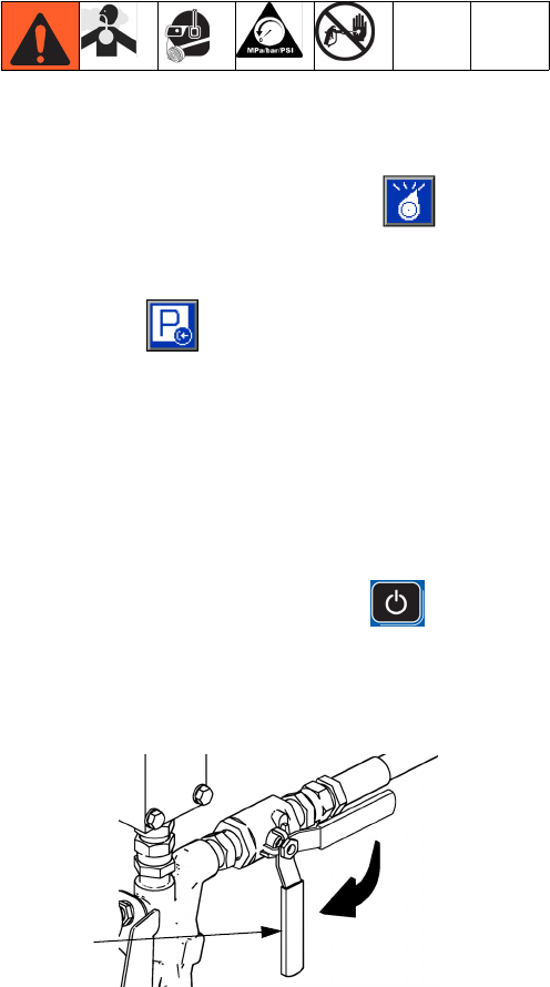
Shutdown
313998S 21
Shutdown
1. Park pumps.
a. From the Home screen, press and select
Standby mode.
b. Press . Material will dispense. Pump will
park automatically. Once pump is parked, pump
will stop moving.
If a dispense gun with a trigger is installed,
pulling the trigger will begin a park operation.
Material will dispense. Continue pulling the trig-
ger until the pump stops moving.
2. Press the power key on the ADM
3. Turn main power switch (MP) to OFF position.
4. Close A (Red) and B (Blue) side fluid supply valves
(FV).
5. Perform Pressure Relief Procedure on page 22.
6. Shut down feed pumps as required. See feed pump
manual.
ti9883a1
FV
Pressure Relief Procedure
22 313998S
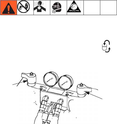
Pressure Relief Procedure
1. Shut off feed pumps and agitator, if used.
2. Turn PRESSURE RELIEF/DISPENSE valves (SA,
SB) to PRESSURE RELIEF/CIRCULATION .
Route fluid to waste containers or supply tanks.
Ensure gauges drop to 0.
3. For models with an EP Gun installed, engage gun
safety lock.
4. Relieve pressure in EP Gun or dispense valve. See
related manual.
ti9879a1
SA
SB
Flushing
313998S 23
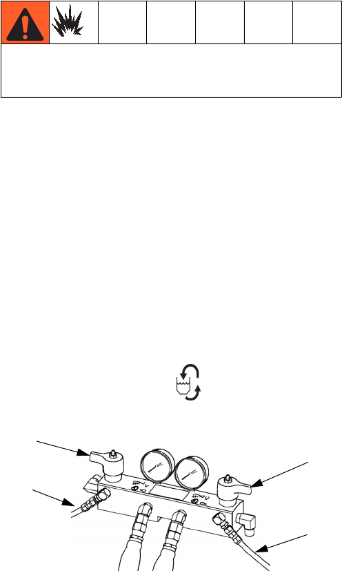
Flushing
• Flush out old fluid with new fluid, or flush out old
fluid with a compatible solvent before introducing
new fluid.
• Use the lowest possible pressure when flushing.
• All fluid components are compatible with common
solvents. Use only moisture-free solvents. See
Technical Data on page 92 for wetted components.
See solvent manufacturers information for material
compatibility.
• To flush feed hoses, pumps, and heaters separately
from heated hoses, set PRESSURE RELIEF/DIS-
PENSE valves (SA, SB) to PRESSURE
RELIEF/CIRCULATION . Flush through bleed
lines (N).
• To flush entire system, circulate through gun fluid
manifold (with manifold removed from gun).
• To prevent moisture from reacting with isocyanate,
always leave the system dry or filled with a mois-
ture-free plasticizer or oil. Do not use water. See
Important Two-Component Material Information
on page 19.
Flush equipment only in a well-ventilated area. Do not
dispense flammable fluids. Do not turn on heaters
while flushing with flammable solvents.
SA
SB
ti9880a1
N
N
Repair
24 313998S
Repair
Pumpline
See Z-Series Chemical Pumps manual, HFR Hydraulic
Driver manuals for more detailed pumpline repair infor-
mation.
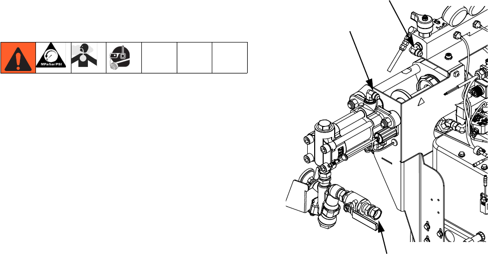
Remove Chemical Pumps
This procedure removes the chemical pumps so that
replacement parts can be installed. See Z-Series Chem-
ical Pumps manual for replacement parts installation
procedure.
1. For models with heat, turn off all heat including
heated hoses and primary heaters.
2. Flush system, see page 23.
3. Perform Shutdown, see page 21.
4. Remove the front pump shroud.
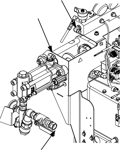
5. Disconnect the chemical pump inlet and outlet fluid
lines. Do not disconnect the fluid manifold inlet line
or the fluid line connections at the heater.
Pump Outlet
Pump Inlet
Fluid Manifold Inlet
24C352_313998_4g1
Repair
313998S 25
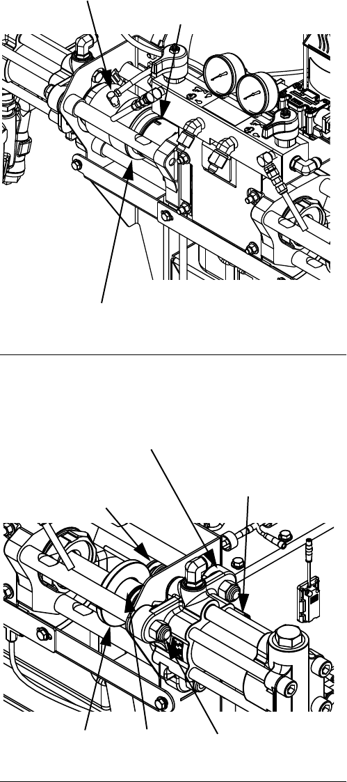
6. Unthread smaller cylinder from hydraulic driver and
slide inside larger cylinder. Use punch slots in lube
cylinder to aid rotation if necessary. See FIG.1.
7. Remove two shoulder bolts from LVDT collar then
remove collar from B side pump shaft. See FIG.2.
8. Remove coupler from the A and B side pump shafts.
See FIG.2.
9. Unscrew LVDT sensor assembly and spool assem-
bly from pump outlet housing. Wipe off spool
assembly. See FIG.2.
10. Remove three nuts securing pump to tie rods. See
FIG.2.
FIG. 1: Lube Cylinder
FIG.2
Lube Cylinder Inlet Fitting (behind cylinder)
Lube Cylinder Outlet Fitting
Punch Slot (same on opposite side)
24C352_313998_2g1
Nuts
LVDT Collar
LVDT Sensor Assembly
(behind pump)
Coupler
LVDT Spool Assembly
Pump Outlet Housing
24C352_313998_2g1
Repair
26 313998S
Install Chemical Pumps
Reconnect or install a different size chemical pump to
achieve desired ratio.
1. Install ISO lube cylinder on A side pump. Apply light
coating of lubricant on o-rings on outside of small
cylinder.
2. Install nuts on tie rods after the pumps have been
installed. Torque to 50-60 ft-lb (68-81 N•m).
3. Install coupler on A and B side pump shafts.
4. Install LVDT Assembly.
a. Apply a very light coat of hydraulic oil on LVDT
sensor tube and install through pump outlet
housing. Install spool assembly.
b. Install LVDT collar on coupler and pump shaft.
Ensure that the split on the LVDT collar does not
ride in the spool assembly.
c. Apply thread sealant to shoulder bolts then
install in LVDT collar. Torque to 40-50 in-lb
(4.5-5.6 N•m).
5. After the IsoGuard Select cylinder has been
installed on the A side pump, apply pipe sealant on
cylinder outlet fitting.
6. Perform Prime IsoGuard Select®Cylinder proce-
dure, see page 26.
7. Reconnect inlet and outlet fluid lines.
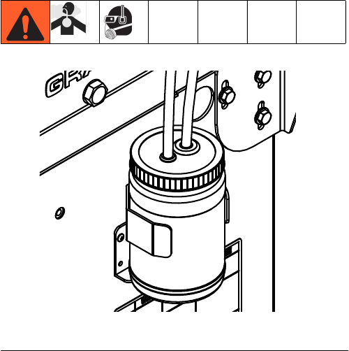
Prime IsoGuard Select®Cylinder
Ensure that the IsoGuard Select cylinder outlet faces
upward for air to exhaust.
1. Install IsoGuard Select cylinder inlet fitting and inlet
tube into bottom of cylinder. The inlet tube is the
tube with a check valve installed in it which points in
the direction of flow towards the IsoGuard Select
cylinder.
2. Install IsoGuard Select cylinder outlet fitting and out-
let tube into top of cylinder. The outlet tube is the
tube with a check valve installed in it which points in
the direction of flow away from the IsoGuard Select
cylinder.
3. Remove check valve from end of outlet tube.
4. Use funnel to pour IsoGuard Select (24F516) into
tube to fill cylinder.
5. With check valve arrow pointing away from the
IsoGuard Select cylinder, install check valve in end
of outlet tube.
6. Install tubes into reservoir and install reservoir into
holder.
FIG. 3: IsoGuard Select System
24C352_313998_8g1
Repair
313998S 27
Remove HFR Hydraulic Driver
This procedure removes the HFR Hydraulic Driver so
replacement parts can be installed. See HFR Hydraulic
Driver manual for replacement parts installation proce-
dure.
1. Perform Remove Chemical Pumps procedure, see
page 24.
2. Disconnect the fluid manifold inlet lines. Do not dis-
connect the fluid line connections at the heater.
3. Remove pump support brackets. Each bracket is
secured with three screws at the base frame and
two screws at the manifold bracket.
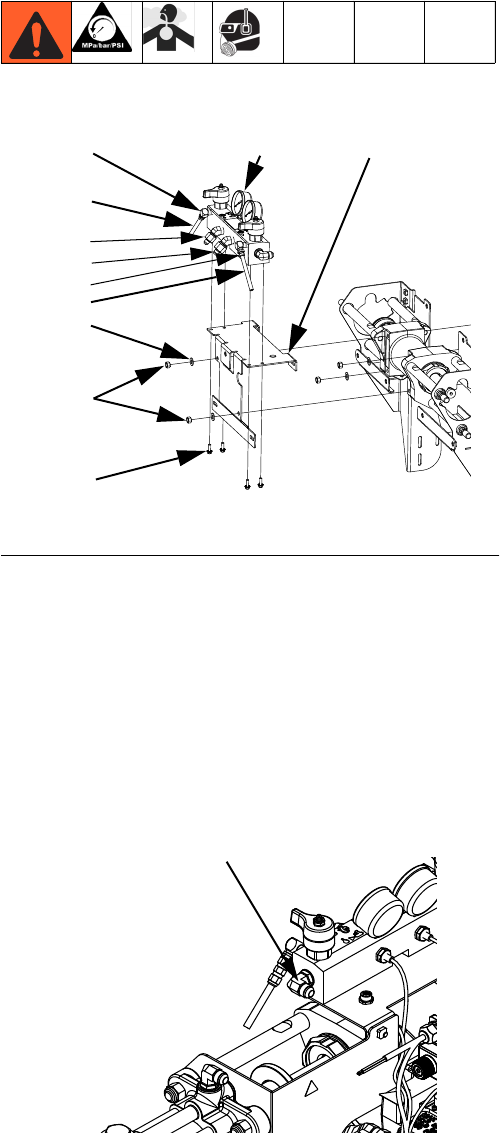
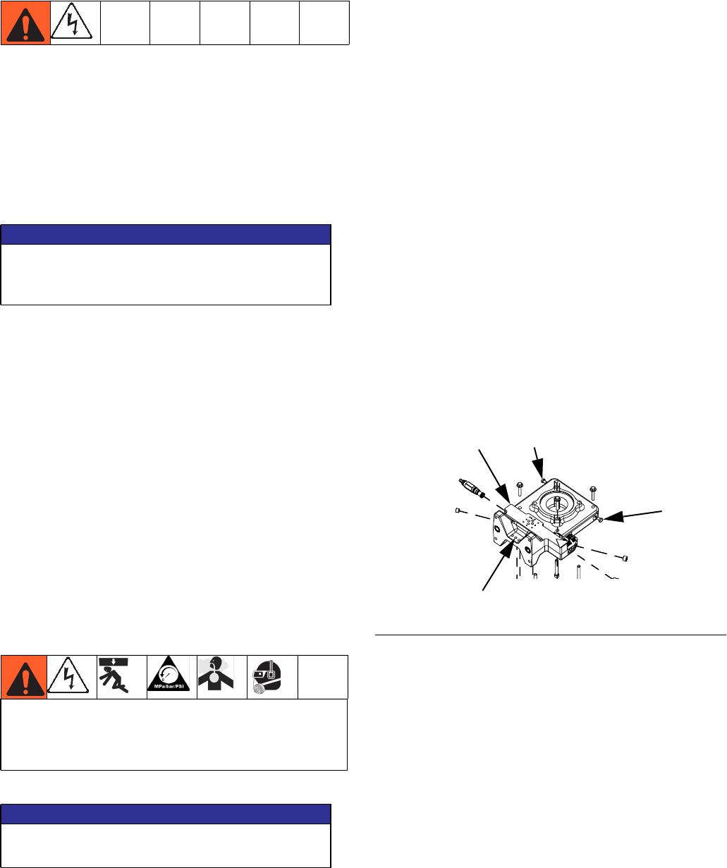
4. See FIG. 4. Remove four nuts (188) securing
hydraulic driver to hydraulic power pack. This will
also loosen manifold plate (104) from hydraulic
driver. Remove manifold plate. Remove hydraulic
driver.
Install HFR Hydraulic Driver
This procedure installs the hydraulic driver after replace-
ment parts have been installed and actuator has been
reassembled. See HFR Hydraulic Driver manual for
replacement parts installation procedure.
1. Hang the hydraulic driver on the studs. Verify o-rings
between driver and hydraulic power pack are
installed and lubricated. Secure the driver with nuts
and washer at bottom-left and top-right corners.
2. Install manifold bracket. Secure at top-left and bot-
tom-right corners.
3. Install pump support brackets, torque to 300 in-lb
(33.9 N•m). This will also install manifold plate (104)
to hydraulic driver.
4. Connect fluid manifold inlet lines.
5. Perform Install Chemical Pumps procedure, see
page 26.
FIG.4
155 104
156
124
125
155
188
156
112
111
180
24C352_313998_5g1
Fluid Manifold Inlet
24C352_313998_4e1
Repair
28 313998S
Remove PowerHouse Pumpline
The Hydraulic Power Pack must be removed to perform
some Hydraulic Power Pack repair procedures. In order
to remove the Hydraulic Power Pack, the PowerHouse
pumpline must be removed. See Hydraulic Power
Pack Repair starting on page 32 for more information.
1. Perform Shutdown procedure, see page 21.
2. Flush the system, see page 23.
3. Disconnect the chemical pump inlet, pump outlet,
and fluid manifold inlet lines. Do not disconnect the
fluid line connections at the heater.
4. Remove lube cylinder inlet and outlet fittings. Let
cylinder drain.
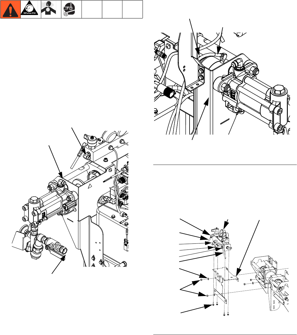
5. See FIG. 6. Remove four screws (107) securing
pumpline to hydraulic power pack. This will also
loosen manifold plate (104) from hydraulic driver.
Pump Outlet
Pump Inlet
Fluid Manifold Inlet
24C352_313998_4e1
FIG. 5: Lube Cylinder, Viewed from Rear Left of
Machine
FIG.6
Lube Cylinder Inlet Fitting
Lube Cylinder Outlet Fitting
Punch Slot (same on opposite side)
24C352_313998_8e1
155 104
156
124
125
155
188
156
112
111
180
24C352_313998_5g1
Repair
30 313998S
Install PowerHouse Pumpline
The Hydraulic Power Pack must be removed to perform
some Hydraulic Power Pack repair procedures. In order
to remove the Hydraulic Power Pack, the PowerHouse
pumpline must be removed. This procedure is for install-
ing the PowerHouse pumpline at the end of the Hydrau-
lic Power Pack Repair procedure. See Hydraulic Power
Pack Repair starting on page 32 for more information.
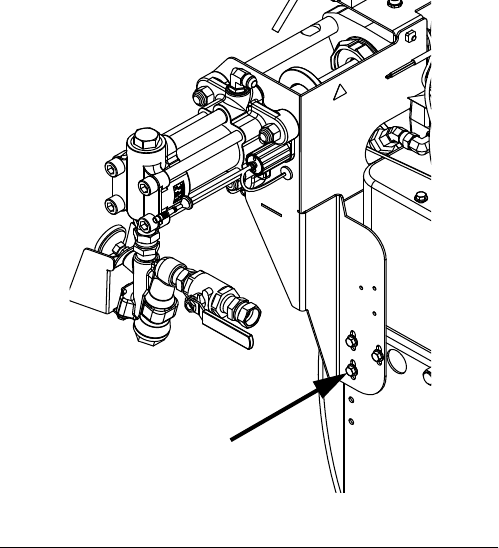
1. While supporting the pumpline, install the three
bolts on each side of the machine securing the
pump support brackets to the machine base. See
FIG. 7. Torque to 150 in-lb (16.9 N•m).
2. See FIG. 6. Align manifold plate (104) with hydraulic
driver. Align hydraulic driver with hydraulic power
pack. Install four screws (107) securing hydraulic
driver to hydraulic power pack. This will also install
manifold plate (104) to hydraulic driver. Torque to
300 in-lb (33.9 N•m).
3. Install lube cylinder inlet and outlet fittings. See FIG.
5. Apply thread sealant to threads.
4. Perform Prime IsoGuard Select®Cylinder proce-
dure, see page 26.
5. Connect the chemical pump inlet, pump outlet, and
fluid manifold inlet lines.
Pump Outlet
Pump Inlet
Fluid Manifold Inlet
24C352_313998_4e1

Repair
313998S 31
Repair
32 313998S
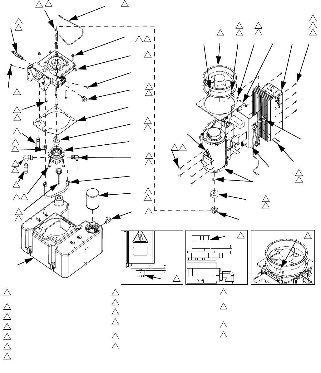
Hydraulic Power Pack Repair
FIG. 8: Hydraulic DC Power Pack
720
725
723
711
710
708
724
713
712
709
714
705
706
719
717
718
746
734
735
715
716
704
729
702
721,
707
701
726 738
737
728
721, 722
744
730733732731745
Assemble coupler to specified dimensions
prior to mounting assembly to housing.
Torque to 40 ft-lb (54 N•m).
Torque to 35 ft-lb (47 N•m).
Torque to 20 ft-lb (27 N•m).
Torque to 15 ft-lb (20 N•m).
Torque to 10 ft-lb (14 N•m).
Torque to 58 in-lb (6.5 N•m).
Torque to 34 in-lb (3.8 N•m).
Torque 1/4 turn past hand-tight.
Apply PTFE tape on installation end only.
Apply medium strength threadlocker prior to
assembly.
Apply light coating of lubricant to seals.
Fill reservoir with hydraulic fluid.
Orient with airflow arrow pointing toward
mounting bracket.
Prior to installing Ref. 728 into Ref. 726,
install Ref. 729 into Ref. 728 and adjust
head 1/8 in. from surface.
Align fan plug as shown.
Apply thermal lubricant to contact side.
1
2
3
4
5
6
7
8
9
10
11
12
13
14
15
24
26
9
11
2
12
3
11 5
10
12
2
12
2
12
311
10
811 26
10
2
12
10
2
12 411
727
511
9
13
6
11
7
11
14 15
11
6
11
8
.45 +.00
-.02
702 1
.30 +.01
-.00
1
702 24
731
257442_3A0998_1j
11
5
11

Repair
313998S 33
Remove Hydraulic Power Pack Shroud
1. Remove four screws from base of shroud.
2. Lift shroud off of Hydraulic Power Pack.
Install Hydraulic Power Pack Shroud
1. Place shroud on top of Hydraulic Power Pack.
2. Install four screws securing shroud to hydraulic tank.
Replace Hydraulic Filter
Filter is located at right rear of hydraulic power pack.
See FIG. 8 on page 32.
1. Perform Shutdown procedure, see page 21.
2. Use compressed air to remove any loose debris
around the hydraulic filter.
3. Remove new filter from wrapping.
4. Apply a light coat of hydraulic fluid to the o-ring on
the face of the hydraulic filter.
5. Being careful not to allow any debris into the
hydraulic tank remove old filter from tank then
quickly install new filter.
Replace Fan
See FIG. 8 on page 32.
1. Perform Shutdown procedure, see page 21.
2. Remove Hydraulic Power Pack Shroud, see pro-
cedure on this page.
3. Remove four screws (732) connecting fan to mount-
ing plate.
4. Remove fan and install new fan.
5. Install four screws (732) connecting fan to Motor
and Motor Control Module.
6. Install Hydraulic Power Pack Shroud, see proce-
dure on this page.
Remove Motor Control Module
See FIG. 8 on page 32.
1. Perform Shutdown procedure, see page 21.
2. Remove Hydraulic Power Pack Shroud, see pro-
cedure on this page.
3. Remove four screws (732) connecting fan to Motor
and Motor Control Module. Remove fan and mount-
ing plate.
4. Note the location of each Motor Control Module
cable then remove all electrical cables on the left
and right sides of the Motor Control Module.
5. Remove six screws (729) securing Motor Control
Module in place.
6. Slowly and carefully slide the Motor Control Module
up until the cable on the bottom of the Motor Control
Module can be accessed and removed. Disconnect
the cable.
7. Slide the Motor Control Module up and remove.
NOTICE
Do not over-torque any item that threads into the
hydraulic tank. This will strip the threads and
require tank replacement.
NOTICE
If any debris falls into the hydraulic tank, the debris
must be removed or machine damage will result.
Repair
34 313998S
Adjust Motor Control Module Selector
Switch
The Motor Control Module uses an 8-position selector
switch (S) to set system maximum working pressure.
See FIG.9.
The system can be configured to run in two pressure
ranges:
•0-3000 psi (0-20.7 MPA, 0-207 bar): For systems
will all components rated to 3000 psi maximum
working pressure or higher.
•0-2000 psi (0-13.8 MPA, 0-138 bar): For systems
with one or more component rated less than
3000 psi maximum working pressure. For example,
if the dispense valve is rated to 2500 psi, then the
0-2000 psi range must be used.
NOTE: The Motor Control Module selector switch (S)
position #1 sets the system to 2000 psi maximum
working pressure. Selector switch position #3 sets
the system to 3000 psi maximum working pressure.
The factory setting for the Motor Control Module selector
switch is position #1 to set the machine to 2000 psi if the
machine is shipped with no hoses or hoses rated to
2000 psi maximum working pressure. If the machine is
shipped with hoses rated to 3000 psi maximum working
pressure or higher then the factory setting for the selec-
tor switch is position #3 to set the machine to 3000 psi.
The selector switch position will be properly set at the
factory for new systems. When a motor control module
is replaced, the selector switch must be set to the cor-
rect setting by the user prior to initial startup.
To change the maximum working pressure rating of the
system in the field, all outlet components including
hoses and dispense valve must be rated at or above the
new system maximum working pressure rating. For
example, if the new system rating will be 3000 psi, all
system components must be rated to at least 3000 psi
maximum working pressure.
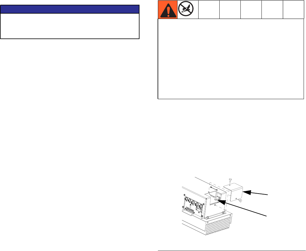
To set the Motor Control Module selector switch:
1. Turn machine power off.
2. Remove the access cover (D). See FIG.9.
3. Set the selector switch (S).
4. Install access cover (D).
NOTICE
If the Motor Control Module is replaced, the selec-
tor switch must be set prior to initial startup of the
Motor Control Module or damage may occur.
• Do not install components rated to less than the
highest pressure in the selected pressure range.
For example, if the 0-2000 psi range is selected do
not install items rated less than 2000 psi. If the
0-3000 psi range is selected do not install items
rated less than 3000 psi. Doing so may lead to
overpressurization and ruptured components.
• High-pressure fluid from ruptured components will
pierce skin. This may look like just a cut, but it is a
serious injury that can result in amputation. Get
immediate surgical treatment.
FIG.9
S
257396_3b9905_04b
D
Repair
313998S 35
Install Motor Control Module
This procedure starts assuming that the old Motor Con-
trol Module is removed from the machine. See Remove
Motor Control Module procedure, see page 33.
See FIG. 8 on page 32.
1. Perform Adjust Motor Control Module Selector
Switch procedure on page 34.
2. Slide the Motor Control Module into the slot.
3. Attach the cable on the bottom of the Motor Control
Module.
4. Install the six screws (729) securing Motor Control
Module in place.
5. Install electrical cables on left and right sides of the
Motor Control Module.
6. Install four screws (732) connecting fan to Motor
and Motor Control Module. Install fan and mounting
plate.
7. Install Hydraulic Power Pack Shroud, see proce-
dure on page 33.
Remove Hydraulic Power Pack
This procedure removes the hydraulic power pack from
the machine as a single unit to enable further disassem-
bly. User must purchase three 5/16-18 eye-bolts capable
of holding 300 lb to perform this procedure.
See FIG. 8 on page 32.
1. Perform Shutdown procedure, see page 21.
2. Perform Remove Hydraulic Power Pack Shroud,
see procedure on page 33.
3. Perform Remove Motor Control Module proce-
dure, see page 33.
4. Perform Remove PowerHouse Pumpline proce-
dure, see page 28.
5. Disconnect heat exchanger inlet hose and fitting
from elbow fitting (617). Disconnect heat exchanger
outlet hose and fitting from elbow fitting (025).
6. Remove the two bolts (746) from the fluid
housing (703) and replace each with a strong
5/16-18 thread eye-bolt. Install a third strong
5/16-18 eye-bolt as indicated. See FIG. 10. See FIG.
8 on page 32 for full hydraulic power pack view.
7. Run a rope through the three eye-bolts and between
the motor and the Motor Control Module. Secure to
a hydraulic lift.
8. Remove the four bolts (604) and washers (603)
securing the tank to the electrical enclosure. See
Power Pack Module on page 52.
9. Lift the hydraulic power pack and place on a sturdy
location capable of supporting up to 300 lbs.
NOTICE
Motor Control Module selector switch position must
be set prior to startup of Motor Control Module or
damage may occur.
The hydraulic power pack weighs up to 300 lb. To
avoid serious injury due the hydraulic power pack fall-
ing, secure the hydraulic lift when raising the hydraulic
power pack.
NOTICE
If any debris falls into the hydraulic tank, the debris
must be removed or machine damage will result.
FIG.10
703 746
746
Install third eye-bolt here
257442_313998_1j1
Repair
36 313998S
Install Hydraulic Power Pack
This procedure assumes the Hydraulic Power Pack has
been removed from the machine and is assembled
except for the Motor Control Module.
See FIG. 8 on page 32.
1. Run a rope through the three eye-bolts and between
the Motor and the Motor Control Module. Secure to
a hydraulic lift.
2. Lift the Hydraulic Power Pack and place onto the
electronic enclosure.
3. Align the holes with the tank then install finger-tight
the four bolts (604) and washers (603) securing the
tank to the electrical enclosure. Torque to 10 ft-lb
(14 N•m).
4. Remove rope and lift.
5. Remove eye-bolts. Install original bolts (746) into
fluid housing (703). See FIG. 10.
6. Perform Install PowerHouse Pumpline procedure,
see page 30.
7. Perform Install Motor Control Module procedure,
see page 35.
8. Connect heat exchanger inlet hose and fitting to
elbow fitting (617). Connect heat exchanger outlet
hose and fitting to elbow fitting located on rear right
face of tank. See Power Pack Module on page 52.
Replace Tank Gasket, Tank
See FIG. 8 on page 32.
1. Perform Remove Hydraulic Power Pack proce-
dure, see page 35.
2. Remove hex head cap screws (722) securing
hydraulic housing (703) to tank (720). Carefully
remove motor (701) and hydraulic housing assem-
bly from tank.
3. Remove tank gasket. If tank is damaged, replace
tank.
4. Install thrust washers (721) onto hex head cap
screws (022). Apply pipe sealant to threads of
screws. Align tank gasket (719), hydraulic housing,
and tank (720) then install screws. Torque to
15 ft-lb (20 N•m).
5. Perform Install Hydraulic Power Pack procedure,
see page 36.
Remove Motor
See FIG. 8 on page 32.
1. Perform Remove Hydraulic Power Pack proce-
dure, see page 35.
2. Remove four hex head cap screws (722) securing
hydraulic housing (703) and motor (701) to
tank (020). Carefully remove motor and hydraulic
housing assembly from tank.
3. Remove four hex head cap screws (727) connecting
mounting bracket (726) to motor.
4. Remove four socket head cap screws (704) secur-
ing motor to hydraulic housing. Carefully remove
motor from hydraulic housing.
NOTICE
If any debris falls into the hydraulic tank, the debris
must be removed or machine damage will result.
NOTICE
Do not over-torque any item that threads into the
hydraulic tank. This will strip the threads and
require tank replacement.
NOTICE
Do not over-torque any item that threads into the
hydraulic tank. This will strip the threads and
require tank replacement.
Repair
313998S 37
5. Loosen set screw for motor coupler (702) then
remove motor coupler.
Install Motor
See FIG. 8 on page 32.
1. Use four hex head cap screws (727) and thrust
washers (721) to install Motor Control Module
mounting bracket (726) onto motor (701).
2. Install motor coupler (702) onto motor (701). Cou-
pler must be 0.65-0.67 in. from the face of the
motor. Torque motor coupler set screw to 15 ft-lb
(20 N•m).
3. Install spider coupler (707) into motor coupler.
4. Use four socket head cap screws (704) to attach
hydraulic housing (703) to motor. Be sure to align
teeth of gear coupler with the teeth of the motor cou-
pler. Apply pipe sealant to threads of screws. Torque
to 35 ft lb (47 N•m).
5. Install thrust washers (721) onto hex head cap
screws (722). Apply pipe sealant to threads of
screws. Align tank gasket (719), hydraulic housing,
and tank (720) then install screws. Torque to 15 ft-lb
(20 N•m).
6. Perform Install Hydraulic Power Pack procedure,
see page 36.
Remove Hydraulic Gear Pump
See FIG. 8 on page 32.
1. Perform Remove Hydraulic Power Pack proce-
dure, see page 35.
2. Remove hex head cap screws (722) securing
hydraulic housing (703) to tank. Carefully remove
motor (701) and hydraulic housing assembly.
3. Remove tube (711).
4. Remove elbow fittings (710, 712) from gear
pump (705).
5. Remove two hex head cap screws (708) securing
gear pump to hydraulic housing.
6. Remove spider coupler (707).
7. Loosen set screw for gear coupler (706) then
remove gear coupler from gear pump.
Install Hydraulic Gear Pump
See FIG. 8 on page 32.
1. Install gear coupler (706) onto gear pump (705).
Coupler must be 0.12 to 0.13 in. from the face of the
gear pump. Torque gear coupler set screw to 15 ft-lb
(20 N•m).
2. Install spider coupler (707) into gear coupler.
3. Use two hex head cap screws (708) to attach gear
pump to hydraulic housing. Be sure to align teeth of
gear coupler with the teeth of the motor coupler.
Torque screws to 35 ft-lb (47 N•m).
4. Apply a light coat of lubricant to seals of elbow
fittings (710, 712). Install elbow fittings into gear
pump. See FIG. 8 on page 32. for fitting alignment.
Torque both fittings to 40 ft-lb (54 N•m).
NOTICE
Do not over-torque any item that threads into the
hydraulic tank. This will strip the threads and
require tank replacement.

Repair
38 313998S
5. Apply a light coating of lubricant to seals of
tube (711). Install tube (711) onto elbow fitting (710)
and straight fitting (709). Hand-tighten then use
wrench to tighten 90 degrees further.
6. Install thrust washers (721) onto hex head cap
screws (722). Apply pipe sealant to threads of
screws. Align tank gasket (719), hydraulic housing,
and tank (720) then install screws. Torque to 15 ft-lb
(20 N•m).
7. Perform Install Hydraulic Power Pack procedure,
see page 36.
NOTICE
Do not over-torque any item that threads into the
hydraulic tank. This will strip the threads and
require tank replacement.
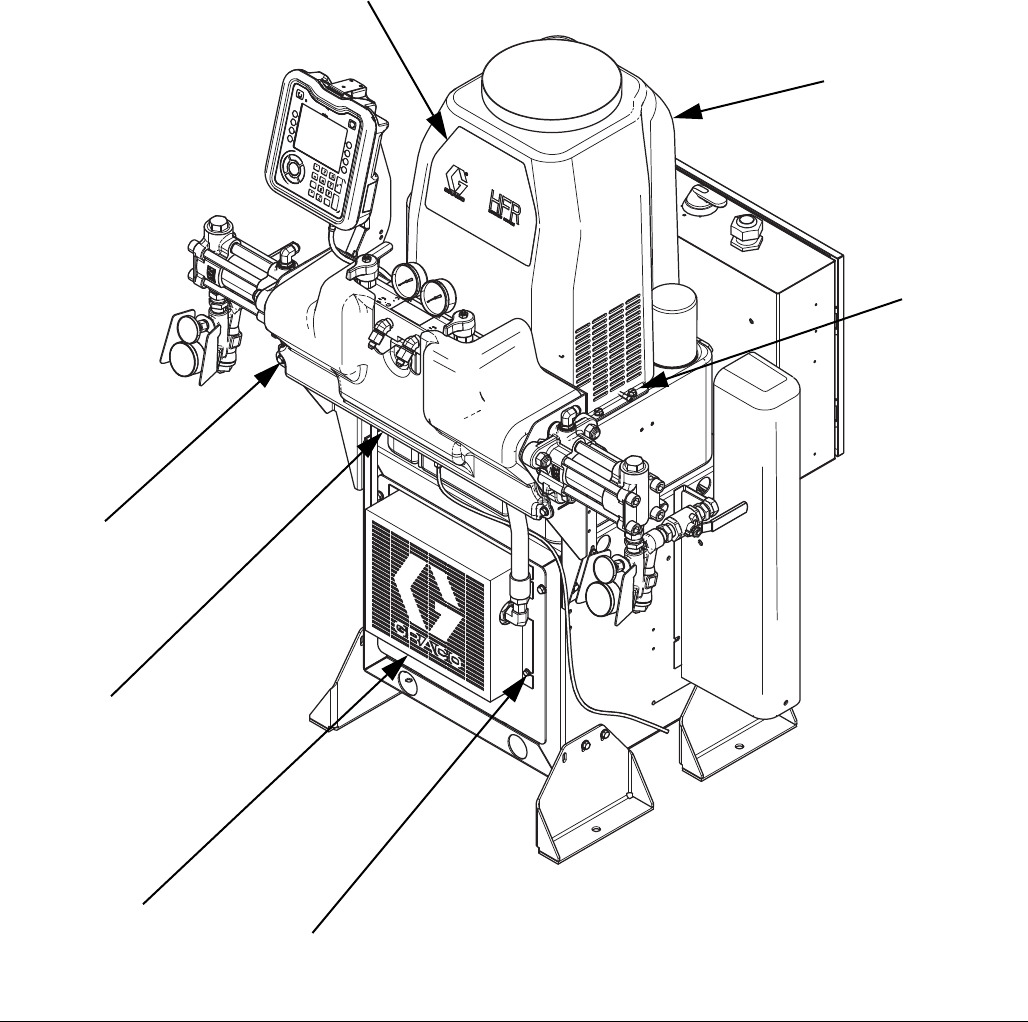
Parts
313998S 39
Parts
Base Machine
FIG. 11: Base Machine, Image 1 of 6
127
193
123
147
112
110
175
ti19598a
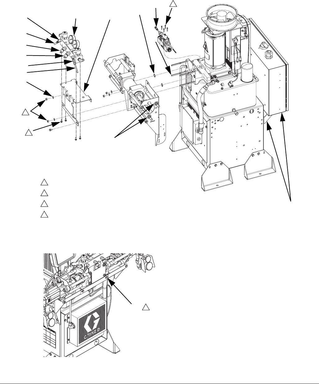
Parts
40 313998S
FIG. 12: Base Machine, Image 2 of 6
155 104
156
124
125
155
156
112
105, 150 151, 165
See Power Distribution
Box manual
Torque to 300 in-lb (34 N•m).
Torque to 79 in-lb (8.9 N•m).
Torque to 62 in-lb (7.0 N•m).
Torque to 150 in-lb (17 N•m).
1
2
3
4
1
188
111 171
2
3
ti19600a
180
110
ti19601a
187
189
110 4
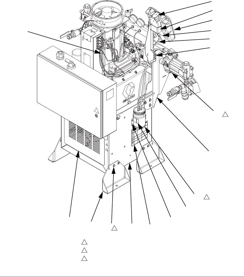
Parts
313998S 41
FIG. 13: Base Machine, Image 3 of 6
161 102 101 176
110
108
132
129
130
128
110
121
115
114
Torque to 40-50 ft-lb (54-68 N•m).
IsoGuard Select fluid, 24F516.
Torque to 17 ft-lb (23 N•m).
1
2
3
1
ti19603a
157
154
158
2
3
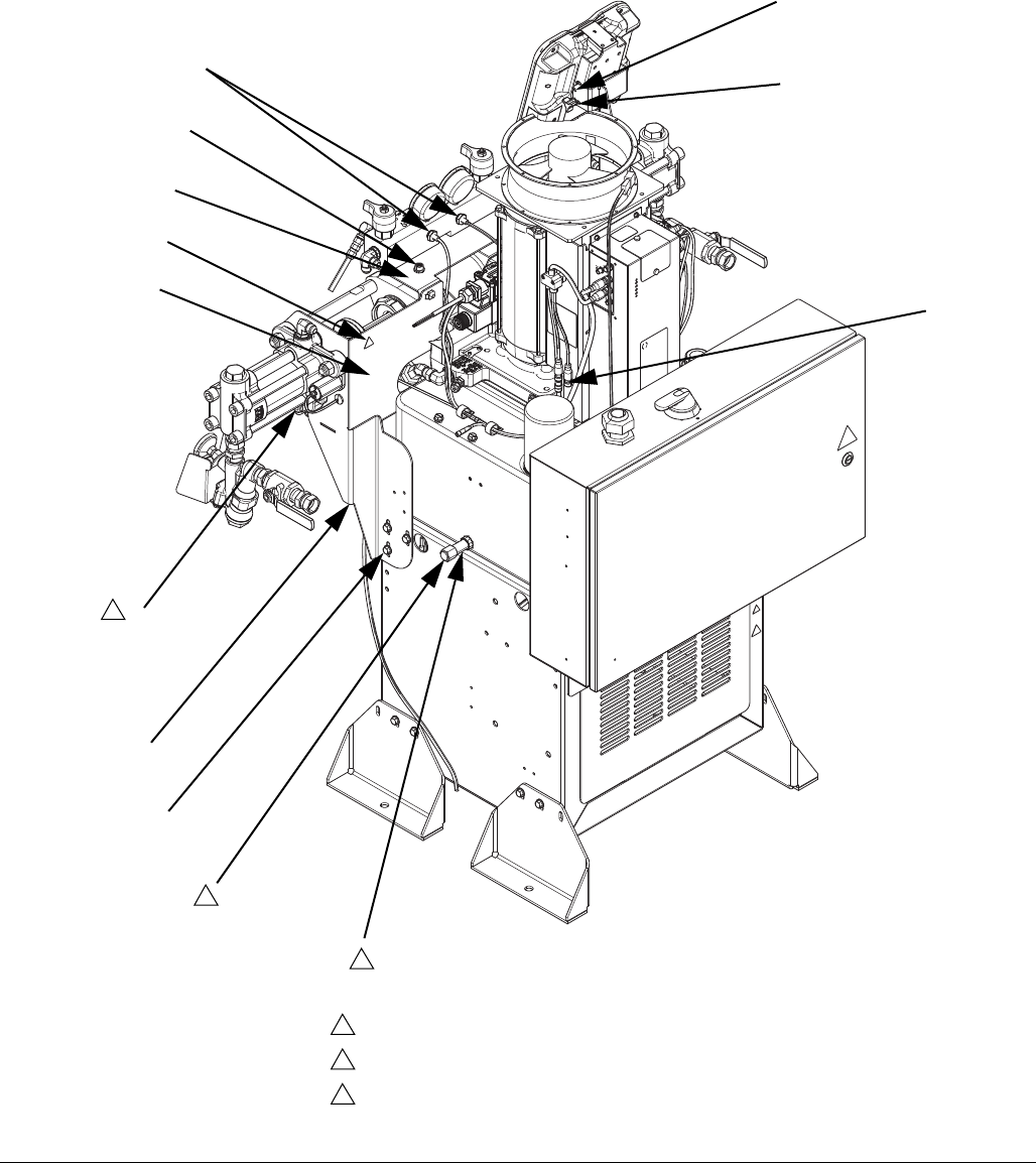
Parts
42 313998S
FIG. 14: Base Machine, Image 4 of 6
118, 119, 120
116, 117
168
110
160
146
132
110
163
Apply sealant to pipe threads.
Do not apply sealant to threads.
Torque to 40-50 ft-lb (54-68 N•m).
1
2
3
2
162 1
3
152, 153
109
ti19604a
168
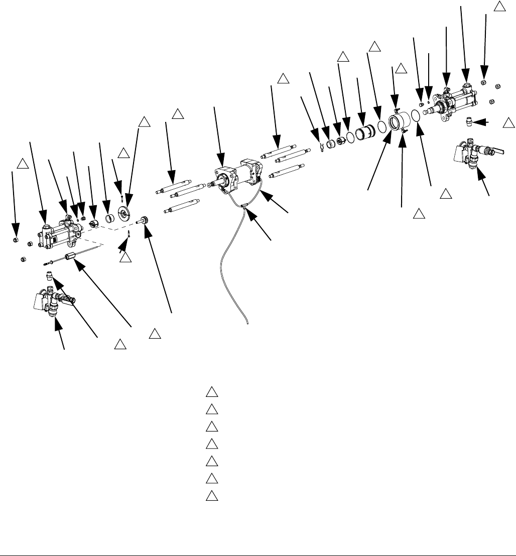
Parts
313998S 43
FIG. 15: Base Machine, Image 5 of 6
126
122
142
132
166
153
183
†
†
143
141 131
106
131
139
136
134
135
144, 145
144, 145
183
153
166
132
122
126
5
Torque to 50-60 ft-lb (68-81 N•m).
Torque to 40-50 ft-lb (54-68 N•m).
Assemble to orientation shown.
Apply sealant to pipe threads.
Apply a very thin coating of lubricant to the sensor tube.
Apply a thin coating of lubricant.
Snug only enough to hold pump module in place until final torque is applied later in
assembly.
1
2
3
4
5
6
7
140
2
6
6
4
4
143 2
135 6
7
31
7
1
4
4
†
†
167
156
133
24C352_313998_9e
†
†
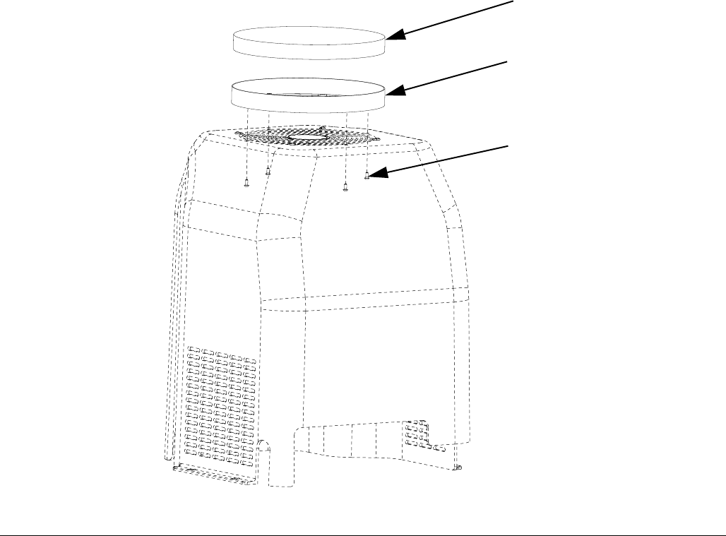
Parts
44 313998S
FIG. 16: Base Machine, Image 6 of 6
24C352_313998_11
194
196
195

Parts
313998S 45
Ref Part Description
Quantity
BASE,
fixed ratio,
non-stainless
BASE,
fixed ratio,
stainless
101 MODULE, power pack, enclosure, assy 1 1
102 24M024 BRACKET, anchor 4 4
104 24E170 BRACKET, manifold 1 1
105 103413 PACKING, o-ring 2 2
106 258771 DRIVER, hydraulic, horizontal 1 1
107 16E281 STUD, threaded, 3/8-16 x 6.0 long 4 4
108 BRACKET, pump, left 1 1
109 BRACKET, pump, right 1 1
110 111800 SCREW, cap, hex head 23 23
111 255629 MANIFOLD, inlet, fluid, h-controller 1
289999 MANIFOLD, fluid, sst 1
112 113796 SCREW, flanged, hex hd 4 4
114 24E647 BRACKET, ADM mounting 1 1
115 255235 BRACKET, mounting, assembly 1 1
116 120060 CLIP, speed, tubular 2 2
117 122168 RIVET, aluminum 2 2
118 110755 WASHER, plain 1 1
119 100016 WASHER, lock 1 1
120 121253 KNOB, display adj. 1 1
121 24E451 MODULE, ADM, w/ USB 1 1
122 123111 FITTING, nipple, hex, 3/4 NPT, 3k, ss 2
C20487 FITTING, nipple, hex 2
123 24C234 COVER, shroud, front 1 1
124 117502 FITTING, reducer #5 x #8 (JIC) 1
16A361 FITTING, reducer, #5 x #8 (JIC), sst 1
125 117677 FITTING, reducer #6 x #10 (JIC) 1
16A362 FITTING, reducer, #6x #10 (JIC), sst 1
126 255159 KIT, assembly, pair, inlet 1
KIT, pair, inlet, sst, no filter 1
127 24B855 COVER, assembly 1 1
128 297216 BRACKET, reservoir, lube 1 1
129 295187 SCREW, machine, ph,8x3/8 2 2
130 258707 RESERVOIR, bottle, assembly 1 1
131 15X519 ROD, tie, 12 lng, 5/8-11 unc 6 6
132 101712 NUT, lock 6 6
133 15Y596 HOUSING, iso lube, telescoping 1 1
134 15Y595 HOUSING, iso lube, telescoping 1 1
135 C20278 PACKING, o-ring 2 2
136 122892 O-RING, fluoroelastomer, 038 1 1
139 125966 CLIP, hairpin 1 1
140 258669 SENSOR, assembly 1 1
141 16A509 COLLAR, sensor, lvdt 1 1
142 258704 SPOOL, assembly, lvdt 1 1
143 119999 BOLT, shoulder 2 2
144 191892 FITTING, elbow, street, 90 deg 2 2
145 116746 FITTING, barbed, plated 2 2

Parts
46 313998S
† See Z-Series Chemical Pumps manual for parts
information.
▲Replacement Danger and Warning labels, tags and
cards are available at no cost.
146 24C235 COVER, pump 1 1
147 24C153 COVER, heat exchanger 1 1
150 123313 VALVE, directional, hydraulic 1 1
151 123366 SCREW, shc, 10-24 x 1.125, s 4 4
152 16A093 SENSOR, pressure, fluid outlet 2 2
153 121399 PACKING, o-ring 012 fx75 4 4
154 121002 CABLE, can, female / female 1.5m 1 1
155 205447 COUPLING, hose 2 2
156 054826 TUBE, plastic 10 10
157 123798 CABLE, m8, 4-pin, mf, 1m, molded 1 1
158 120999 RESISTOR, terminal, turck rke 57-tr2 1 1
160 15H108▲LABEL, pinch point 1 1
161 COVER, enclosure, slotted, assembly 1 1
162 122970 FITTING, adapter, JIC (08) x sae (08), m 1 1
163 123140 FITTING, cap, 1/2 JIC, cs 1 1
164 SEALANT, pipe, sst 1 1
165 SEALANT, anaerobic 1 1
166 121312 FITTING, elbow, sae x JIC 2
123108 FITTING, elbow, 3/4 sae x 1/2 JIC, sst 2
167 123112 FITTING, t, 1/4 tube, prestolock, brass 1 1
168 121581 HARNESS, I/O, M12 x M12 1 1
170 054175 TUBE, nylon, rd 5 5
171 LUBRICANT, grease 1 1
173 24F516 FLUID, ISO-Guard Select, 6 qt. 1 1
174 LABEL, identification 1 1
175 LABEL, HFR metering system 1 1
176 15M511▲LABEL, warning, eng/span/fre 1 1
177 FLUID, hydraulic (gallon) 9 9
178 117792 GUN, grease, 3 oz 1 1
179 117773 LUBRICANT, grease, food grade 1 1
180 555621 WASHER, 3/8 plain flat 4 4
181 15V551 SHIELD, membrane, ADM 0.100 0.100
187 16E277 BUSHING, flanged, 1.0 x 1.25 x 1.0 4 4
188 U90126 NUT, hex, 3/8-16, ms, gr8 4 4
189 071019 ADHESIVE, anaerobic 1 1
193 124804 SCREW, hex, slotted 4 4
194 15U075 SCREW, cap, bh, 8-32 x 0.37 4 4
195 24H018 FILTER, air 1 1
196 16G251 HOUSING, filter 1 1
199 16H821 TOKEN, software upgrade 1 1
Ref Part Description
Quantity
BASE,
fixed ratio,
non-stainless
BASE,
fixed ratio,
stainless
Parts
313998S 47
Base Machine Sub-Assemblies
HFR Hydraulic Driver 258771
See the HFR Hydraulic Driver manual 3A0020 for parts
information.
Z-Series Chemical Pumps
See the Z-Series Chemical Pumps manual for parts
information.
Power Distribution Boxes
See the Power Distribution Boxes manual for parts infor-
mation.
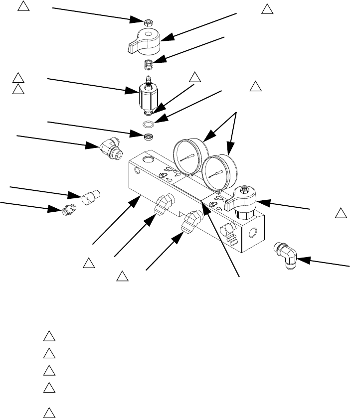
Parts
48 313998S
Non-Stainless Steel Fluid Manifold 255629,
Stainless Steel Fluid Manifold 289999
Aluminum Manifold with Stainless Steel Fittings, 24P166
308
302
302b
314
315
304
301
312
313 317
314
303
302a
318
306
Torque to 355-395 in-lb (40.1-44.6 N•m)
Apply sealant (113500) to threads.
Valve must be closed with handle position as shown on drawing.
Adapter fittings for hoses are included in base machine parts. See Base Machine
starting on page 39 for part numbers.
For assembly 24P166, replace o-ring that comes standard with item 302.
**Apply PTFE or thread sealant to tapered threads.
1
2
3
4
5
2
1
3
3
2
3
307
255629_313998_1a
4
4
5

Parts
313998S 49
▲Replacement Warning labels, signs, tags, and cards
are available at no cost.
† Included in the following complete valve kits*:
Assembly 255629
A (Red) Valve Kit (left/red handle) 255149.
B (Blue) Valve Kit (right/blue handle) 255150.
Valve Set Kit (both handles and grease gun) 255148.
Assembly 289999:
A (Red) Valve Kit (left/red handle) 24E309.
B (Blue) Valve Kit (right/blue handle) 24E310.
Valve Set Kit (both handles and grease gun) 24E308.
* Complete valve kits also include thread sealant.
(Purchase kits separately).
** When replacing item 302, item 302a must be
ordered to replace the standard o-ring that comes
with item 302.
Ref
Part
Description
Qt
y
Assembly
255629
Assembly
289999
Assembly
24P166
301 247837 24E307 255228 MANIFOLD, fluid 1
302† 247824 24E306 24E306** VALVE, drain cartridge 2
.302a 158674† 158674† 556560** . O-RING 1
302b† 247779 247779 247779 . SEAL, seat, valve 1
303 102814 112941 112941 GAUGE, pressure, fluid 2
304 162453 166846 166846 FITTING 2
306 247788 247788 247788 HANDLE, red 1
307 247789 247789 247789 HANDLE, blue 1
308† 112309 112309 112309 NUT, hex, jam 2
312 117556 123106 123106 NIPPLE, #8 JIC x 1/2 npt 1
313 117557 123107 123107 NIPPLE, #10 JIC x 1/2 npt 1
314 121312 123108 126565 ELBOW, 90 degrees 2
315 100840 166866 166866 ELBOW, street, 1/4 npsm x
1/4 npt
2
317▲189285 189285 189285 LABEL, caution 1
318† 150829 150829 150829 SPRING, compression 2
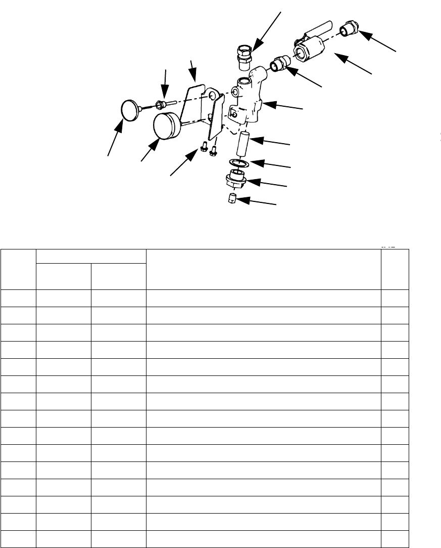
Parts
50 313998S
Non-SST Fluid Inlet Assemblies, 255159
Aluminum Fluid Inlet Assemblies with Stainless Steel Fittings, 24P167
--- Not available for individual sale.
ti9841a1
405 406
414
410
409
408
407
404
403
402
401,
412
413
401
A Side Shown
** Apply sealant to all non-swivel fittings.
411
Ref
Part
Description Qty
Assembly
255159
Assembly
24P167
401 118459 112268 UNION, swivel; 3/4 npt(m) 3/4 npsm(f) 3
402 --- --- VALVE, ball; 3/4 npt (FBE) 2
403 --- --- NIPPLE; 3/4 npt 2
404 247503 247503 MANIFOLD, strainer, inlet 2
405 102124 102124 THERMOMETER, dial 2
406 120300 120300 GAUGE, pressure, fluid 2
407 180199 180199 ELEMENT, filter; 20 mesh (standard) 2
408 15H200 15H200 GASKET, strainer; PTFE 2
409 15H199 15H199 PLUG, strainer 2
410 --- --- PLUG, pipe; 3/8 npt 2
411 296178 123980 UNION, swivel; 3/4 npt(m) x 1/2 npt(f); A side only 1
412 15D757 15D757 HOUSING, thermometer 2
413 253481 253481 GUARD, gauge 2
414 111800 111800 SCREW, cap, hex hd, 5/16-18 x 5/8 in. (16 mm) 4
415 --- --- SEALANT, pipe, sst 1
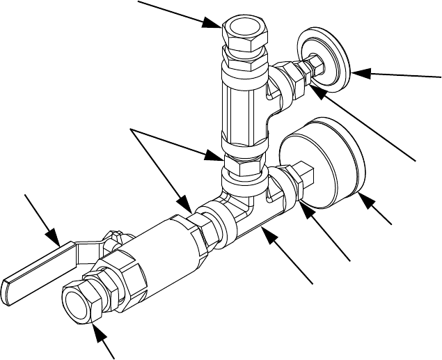
Parts
313998S 51
SST Fluid Inlet Assemblies
506
** Apply sealant and tape to all non-swiveling threads.
508
504
503
502
501
505,
507
509
501, 512
B (Blue) Side Assembly shown,
A (Red) Assembly also included
24D285_313998_1a
Ref Part Description Qty
501 112268 SWIVEL, union 3
502 512485 VALVE, ball, sst 2
503 123111 FITTING, nipple, hex, 3/4npt,
3k, ss
4
504 501118 FITTING, tee 4
505 102124 THERMOMETER, dial 2
506 120300 GAUGE, press, fluid,
(waterborne)
2
507 500352 BUSHING, hex hd, sst 2
508 516308 FITTING, bushing, reducer,
sst
2
509 15D757 HOUSING, thermometer,
Viscon®hp
2
510 SEALANT, pipe, sst 1
511 TAPE, tfe, sealant 1
512 123980 FITTING, straight, swivel, 1/2
x 3/4, FM, sst
1
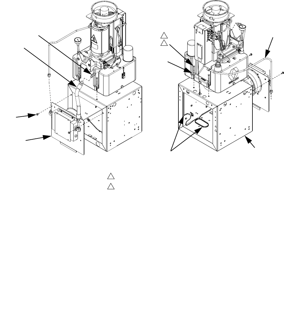
Parts
52 313998S
Power Pack Module
▲Replacement Danger and Warning labels, tags and
cards are available at no cost.
608
609
606
605
601
603
604
607
610
Torque to 10 ft-lb (14 N•m).
Apply sealant to threads.
1
2
2
1
24C273_313998_1d 24C273_313998_2d
Ref Part Description Qty
601 ENCLOSURE, frame, painted 1
602 MODULE, hydraulic power 1
603 U90205 WASHER, flat, 3/8, 0.41 x 1.25 x 0.13, ms 4
604 802277 SCREW, machine (matrix) 4
605 COVER, enclosure, heat exch, assy 1
606 111800 SCREW, cap, btn hd (matrix) 2
607 15Y935 TUBE, heat exchanger, outlet 1
608 24C621 HOSE, heat exchanger, inlet 1
609 123528 FITTING, elb, swvl, 45, jic08, fm, 6k 1
610 24C518 CORD, fan, heat exch, mcm 2
611 SEALANT, anaerobic 1
612 189930▲LABEL, caution, electric shock (not shown) 1
613 15H108▲LABEL, pinch point (not shown) 1

Parts
313998S 53
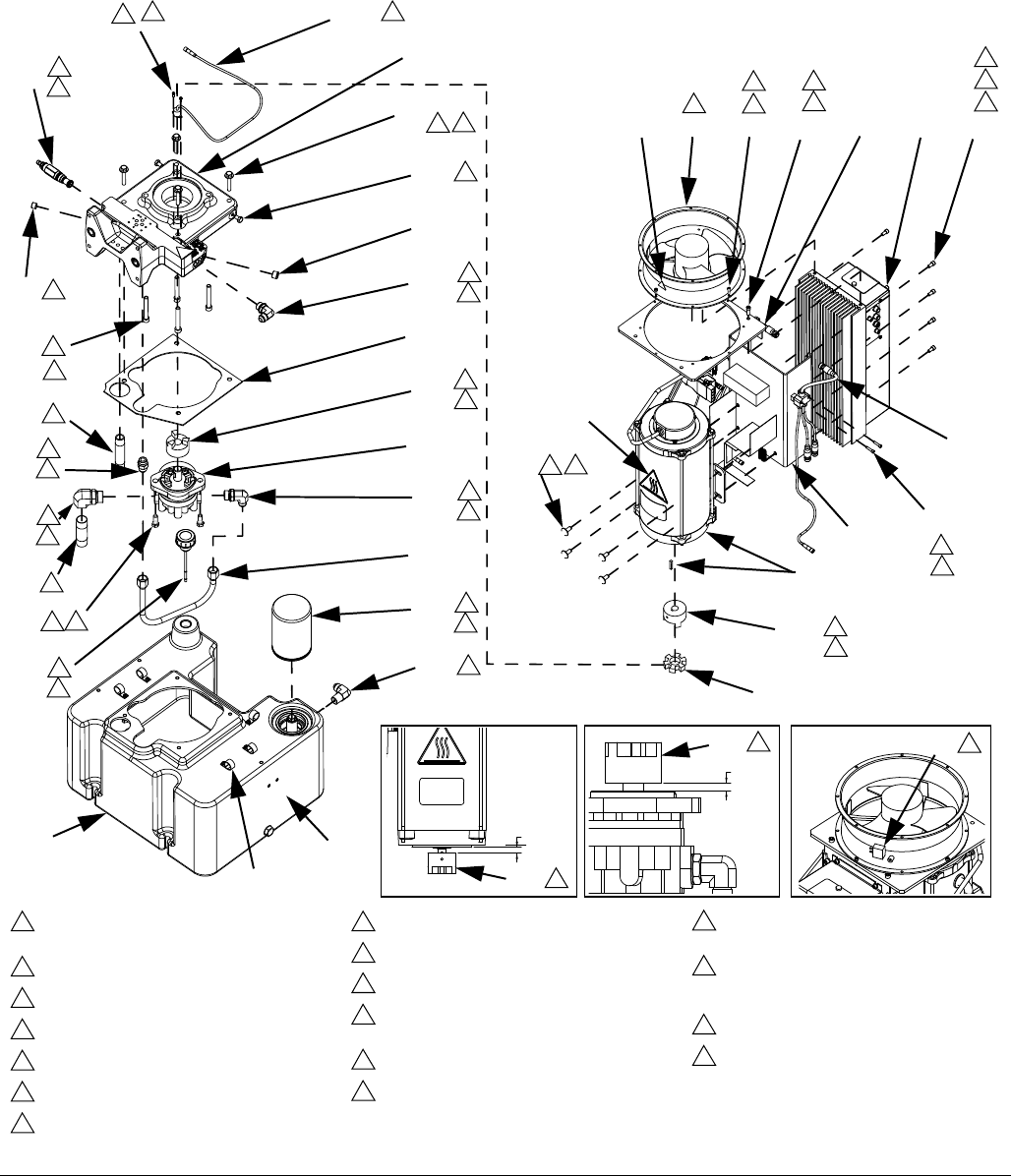
Parts
54 313998S
Power Pack Module Sub-Assemblies
Hydraulic DC Power Pack Module
FIG. 17: Hydraulic DC Power Pack
720
725
723
711
710
708
724
713
712
709
714
705
706
719
717
718
746
734
735
715
716
704
729
702
721,
707
701
726 738
737
728
721, 722
744
730733732731745
Assemble coupler to specified dimensions
prior to mounting assembly to housing.
Torque to 40 ft-lb (54 N•m).
Torque to 35 ft-lb (47 N•m).
Torque to 20 ft-lb (27 N•m).
Torque to 15 ft-lb (20 N•m).
Torque to 10 ft-lb (14 N•m).
Torque to 58 in-lb (6.5 N•m).
Torque to 34 in-lb (3.8 N•m).
Torque 1/4 turn past hand-tight.
Apply PTFE tape on installation end only.
Apply medium strength threadlocker prior to
assembly.
Apply light coating of lubricant to seals.
Fill reservoir with hydraulic fluid.
Orient with airflow arrow pointing toward
mounting bracket.
Prior to installing Ref. 728 into Ref. 726,
install Ref. 729 into Ref. 728 and adjust
head 1/8 in. from surface.
Align fan plug as shown.
Apply thermal lubricant to contact side.
1
2
3
4
5
6
7
8
9
10
11
12
13
14
15
24
26
9
11
2
12
3
11 5
10
12
2
12
2
12
311
10
811 26
10
2
12
10
2
12 411
727
511
9
13
6
11
7
11
14 15
11
6
11
8
.45 +.00
-.02
702 1
.30 +.01
-.00
1
706 24
731
_313998_1j
748, 749
736
703
11
5
11
Parts
313998S 55
▲Replacement Danger and Warning labels, tags and
cards are available at no cost.
Ref Part Description Qty
701 24C719 MOTOR, power connector, assembly 1
702 16A951 COUPLER, motor 1
703 15W772 HOUSING, machined.hydraulic, module 1
704 123338 SCREW, shc, 3/8-16 x 2.75, s(matrix) 4
705 122295 PUMP, gear, hydraulic, h39 1
706 16A952 COUPLER, pump 1
707 16A953 COUPLER, spider 1
708 123942 SCREW, cap, hex hd (matrix) 2
709 15T939 FITTING, straight, jic8 x sae8 1
710 122520 FITTING, elbow, male, sae x jic 1
711 15W798 TUBE, pump to tube outlet 1
712 122606 FITTING, elbow, male, female 1
713 115597 NIPPLE 1
714 101353 FITTING, nipple, pipe 1
715 122527 VALVE, relief, t-10a cavity, 0-25g 1
716 100721 PLUG, pipe 1
717 121312 FITTING, elbow, sae x jic 1
718 101754 PLUG, pipe 1
719 15X622 GASKET, housing, to, tank 1
720 RESERVOIR, assembly, 8 gallon 1
721 101971 WASHER, thrust 4
722 111302 SCREW, cap, hex hd (matrix) 4
723 15J937 FILTER, oil, 18-23 psi bypass 1
724 116915 CAP, breather filler 1
725 121486 FITTING, elbow, male, 1/2jic x 1/2npt 1
726 15Y912 BRACKET, mcm mounting 1
727 100057 SCREW, cap hex hd (matrix) 4
728 257396 MODULE, motor control 1
729 101550 SCREW, cap, sch (matrix) 7
730 PLATE, mounting, fan 1
731 122301 FAN, 220v 1
732 112310 SCREW, cap, sch (matrix) 8
733 100644 SCREW, cap, sch (matrix) 2
734 123367 HARNESS, m8 x thermal switch, 4-pin 1
735 102410 SCREW, cap soc hd (matrix) 1
736 FLUID, hydraulic (gallon) 8
737 123303 HARNESS, m12 2
738 295709 SCREW, soc.hd (matrix) 4
739 LUBRICANT, grease 1
740 SEALANT, pipe, sst 1
741 SEALANT, pipe, sst 1
743 189285▲LABEL, caution 1
744 121208▲LABEL, hot surface 1
745 15H108▲LABEL, pinch point 1
746 109468 SCREW, cap, hex head 2
747 LUBRICANT, thermal 1
748 123601 CLAMP, wire, harness, nylon, 3/4 5
749 103833 SCREW, mach, crbh 5
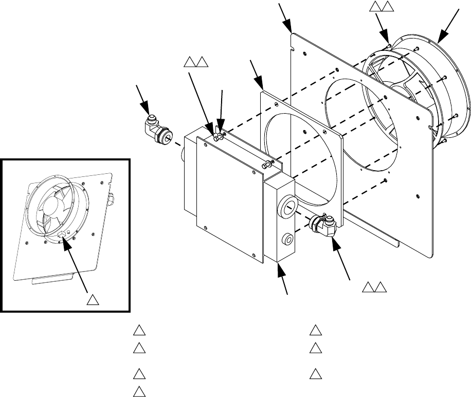
Parts
56 313998S
Heat Exchanger Assembly
801 804
806
802
807
805
Torque to 65 ft-lb (88 N•m).
Apply lubricant to o-rings before
assembling.
Torque to 8 ft-lb (11 N•m).
Torque to 2.5 ft-lb (3.4 N•m).
Apply sealant to threads.
Orient fan with airflow arrow pointing
toward cover.
Align fan plug as shown.
1
2
3
4
5
6
7
7
805
4 5
3 5
808
803
1 2
257931_313998_1f
257931_313998_2f
Ref Part Description Qty
801 257967 COVER, enclosure, heat exch,
painted
1
802 15X621 GASKET, fan, mounting 1
803 122300 EXCHANGER, heat, m-4 1
804 122301 FAN, 220v 1
805 122842 FITTING, elbow, sae x jic 2
806 15U075 SCREW, cap, bh, 8-32 x
.37(matrix)
8
807 110755 WASHER, plain 4
808 100022 SCREW, cap, hex hd (matrix) 4
810 LUBRICANT, thread 1
811 SEALANT, anaerobic 1
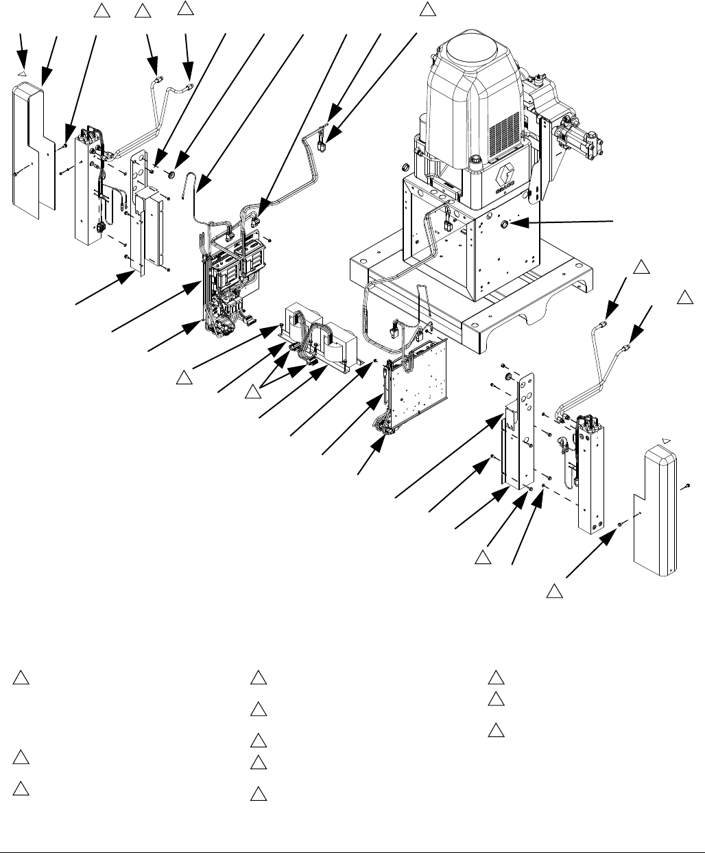
Parts
313998S 57
Heater Options
FIG. 18: Heater Options, Image 1 of 4
Assembly NPT portion of Ref. 938 into Ref.
907. Tighten to tight minus 1 turn
approximately. Insert Ref. 933 into Ref. 938
an tighten while holding against heater
element. Tighten ferrule to 21-25 ft-lb
(28-34 N•m). Hold NPT portion to prevent
tightening.
Tighten NPT thread at least one turn after
RTD has been tightened.
Apply thermal lubricant when assembling
Ref. 934.
Apply oxide inhibitor to bare ends of wires
and to ferrule ends.
Apply oxide inhibitor included in Ref. 917 to
bare ends of wires and to ferrule ends.
Torque to 16 in-lb (1.8 N•m).
Connect to Ref. 920 through extension
cable.
Choose adapter and swivel fitting from kit
based on hose size.
Torque to 17 ft-lb (23 N•m).
Apply lubricant to threads of tube fitting and
torque to 21 ft-lb (28 N•m).
Apply sealant and tape to all non-swiveling
and non-o-ring threads.
1
2
3
4
5
6
7
8
9
10
12
922 910 908 913 914
908
925
903
901
906
908
905
929 930
916
918919 917
912
911
909
931
932
902
926
5
6
10 10
9
9
9
908 9
10
10
920
24C327_313998_1L
904
904
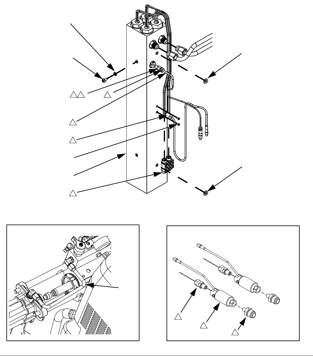
Parts
58 313998S
FIG. 19: Heater Options, Image 2 of 4
1
935
934
933
938
928
927
921
905
907
905
Non-Heated Models Only
915
1
212
3
4
Ref. 924, 258757 shown
8
8
7
24C327_313998_1L
24C327_313997_9f
24C327_313998_2L

Parts
313998S 59
Ref Part Description
Quantity
A (Red) and B (Blue) Primary Heaters,
A (Red) and B (Blue) Hose Heat
A (Red) and B (Blue) Primary Heaters,
One Zone of Hose Heat
A (Red) and B (Blue) Hose Heat,
Stainless Steel
A (Red) and B (Blue) Hose Heat,
Carbon Steel
A (Red) and B (Blue) Primary Heaters
B (Blue) Primary Heaters,
B (Blue) Hose Heat
No Heat
901 MODULE, panel, pwr, heat, hose, pr, lv 1 1
MODULE, panel, pwr, heat, hose, lv 1 1
MODULE, panel, pwr, heat, pri, lv 1
902 MODULE, panel, pwr, heat, hose, pr, hv 1 1
MODULE, panel, pwr, heat, hose, hv 1 1
MODULE, panel, pwr, heat, pri, hv 1 1
MODULE, panel, pwr, no heat, hv 1
903 115942 NUT, hex, flange head 6 6 6 6 6 3 3
904 253192 BRACKET, painted, heater mount, poly 2 2 2 1
905 167002 INSULATOR, heat 4 4 4 2
906 113796 SCREW, flanged, hex hd (matrix) 4 4 4 2
907 24C426 HEATER, assy, 6kw, 1-zone, rtd, s 2 2 2 1
908 111800 SCREW, cap, hex hd (matrix) 16 14 4 4 12 8
909 255360 COVER, wire, heater, painted 2 2 2 1
910 253196 COVER, painted, heater, poly, h-25 2 2 2 1
911 16A104 TUBE, fluid, a, inlet, heater, ams 1 1 1
912 16A105 TUBE, fluid, a, outlet, heater, ams 1 1 1
913 16A106 TUBE, fluid, b, inlet, heater, ams 1 1 1 1
914 16A107 TUBE, fluid, b, outlet, heater, ams 1 1 1 1
915 16A108 TUBE, fluid, no heater, ams 2 2 1 2
916 24C418 MODULE, transformer, assy, hv 1 1 1 1 1
917 261821 CONNECTOR, wire, 6awg 2 1 2 2 1
918 24C314 HARNESS, wire, hptcm, hoseheat, fixed 2 1 2 2 1
919 24C312 HARNESS, wire, hptcm, heater, fixed 2 2 2 1
920 122242 CABLE, m8, 4-pin, mf, 2.5m, mold 2 1 2 2 1
921 255716 KIT, heater wire connector 1 1 1 1
922 189285▲LABEL, caution 2 2 2 1
923 FLUID, oxide inhibitor 1 1 1 1
924 258756 KIT, fts, rtd, dual hose, sst 1
258757 KIT, fts, rtd, dual hose 1 1
258758 KIT, fts, rtd, single hose 1 1
925 24C779 MODULE, transformer, assy, lv 1 1 1

Parts
60 313998S
▲Replacement Danger and Warning labels, tags and
cards are available at no cost.
926 123398 PLUG, hole, 1.5"dia 2 2 2
123589 BUSHING, wire protector, snap-in 2 2 2 2
927 100028 WASHER, lock 2 2 2 1
928 113783 SCREW, machine, pn hd (matrix) 2 2 2 1
929 103361 BUSHING, snap 2 2 2 1
930 114269 GROMMET, rubber 2 2 2 1
931 121002 CABLE, can, female / female 1.5m 1 1 1 1 1 1
932 122487 CABLE, can, male-female, 1.5m 1 1 1 1 1
933 124262 SENSOR, rtd, 1 k ohm, 5 ft, 4 pin, tip
sensor
2 2 2 1
934 123408 HARNESS, m8 x thermal switch, 3-pin 2 2 2 1
935 100518 SCREW, mach, pnhd (matrix) 4 4 4 2
936 LUBRICANT, thermal 1 1 1 1
937 LUBRICANT, thread 1 1 1 1 1 1 1
938 123325 FITTING, compression, 1/8npt, ss 2 2 2 1
939 SEALANT, pipe, sst 1 1 1 1
940 TAPE, tfe, sealant 1 1 1 1
Ref Part Description
Quantity
A (Red) and B (Blue) Primary Heaters,
A (Red) and B (Blue) Hose Heat
A (Red) and B (Blue) Primary Heaters,
One Zone of Hose Heat
A (Red) and B (Blue) Hose Heat,
Stainless Steel
A (Red) and B (Blue) Hose Heat,
Carbon Steel
A (Red) and B (Blue) Primary Heaters
B (Blue) Primary Heaters,
B (Blue) Hose Heat
No Heat
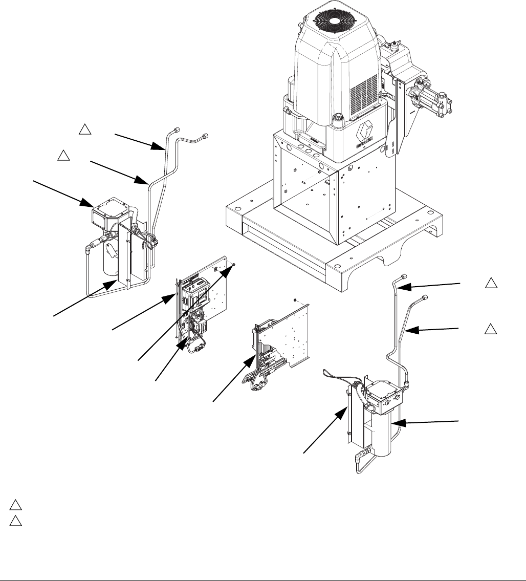
Parts
313998S 61
FIG. 20: Heater Options, Image 3 of 4
Torque to 17 ft-lb (23 N•m).
Apply lubricant to threads of tube fitting and
torque to 21 ft-lb (28 N•m).
9
10
10
1331
ti17873a
1303
1302
1301
1332 1342
1312
1311
1341
1314
1313
1342
1341
10
10
10
24J707 Shown
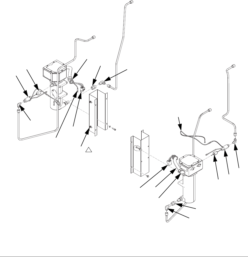
Parts
62 313998S
FIG. 21: Heater Options, Image 4 of 4
ti17874a
9
1308
1354
1334
1343
1345
1344
1348
1346 1347
1354 1349
1353
1347
1346
1344
1345
1343
1351
1350

Parts
313998S 63
Quantity
Ref Part Description
24G617, HEATER, fix, pr,
1hose, 1fts, viscon
24J105, HEATER, fix, pr, 1
viscon, 1 std
24J106, HEATER, fix, pr, 1
vis, 1 std, 2 hose
24J107, HEATER, fix, pr,
2viscon
24J108, HEATER, fix, pr, 2
viscon, 1 hose
24J109, HEATER, fix, pr, 2
viscon, 2 hose
1301 24C336 MODULE, panel, pwr, heat, hose, pr, lv 1 1 1 1
24C338 MODULE, panel, pwr, heat, pri, lv 1 1
1302 24C332 MODULE, panel, pwr, heat, hose, pr, hv 1 1
24C334 MODULE, panel, pwr, heat, pri, hv 1 1 1 1
1303 115942 NUT, hex, flange head 6 6 6 6 6 6
1304 253192 BRACKET, painted, heater mount, poly 1 1 1
1305 167002 INSULATOR, heat 2 2 2
1306 113796 SCREW, flanged, hex hd 2 2 2
1307 24C426 HEATER, assy, 6kw, 1-zone, rtd, s 1 1 1
1308 111800 SCREW, cap, hex hd 10 10 14 8 10 12
1309 255360 COVER, wire, heater, painted 1 1 1
1310 253196 COVER, painted, heater, poly, h-25 1 1 1
1311 16A104 TUBE, fluid, a, inlet, heater, ams 1 1 1
16H486 TUBE, fluid, outlet 1 1 1
1312 16A105 TUBE, fluid, a, outlet, heater, ams 1 1 1
16H485 TUBE, fluid, inlet 1 1 1
1313 16G338 TUBE, fluid, b, inlet, heater, visc 1 1 1 1 1 1
1314 16G339 TUBE, fluid, b, outlet, heater, vis 1 1 1 1 1 1
1316 24C418 MODULE, transformer, assy, hv 1 1 1 1
1317 261821 CONNECTOR, wire, 6awg 1 2 1 2
1318 24C314 HARNESS, wire, hptcm, hoseheat, fixed 1 2 1 2
1319 24C312 HARNESS, wire, hptcm, heater, fixed 1 1 1
1320 122242 CABLE, m8, 4-pin, mf, 2.5m, mold 1 2 1 2
1321 255716 KIT, heater wire connector 1 1 1
1322 189285 LABEL, caution 1 1 1
1323 261843 FLUID, oxide inhibitor 1 1 1 1 1 1
1324 258756 KIT, fts, rtd, dual hose, sst 1 1
258758 KIT, fts, rtd, single hose 1
24G976 KIT, fts, rtd, single hose, 1/2-2 1
1325 24C779 MODULE, transformer, assy, lv 1 1
1327 100028 WASHER, lock 1 1 1
1328 113783 SCREW, machine, pn hd) 1 1 1
1329 103361 BUSHING, snap 1 1 1
1330 114269 GROMMET, rubber 1 1 1
1331 121002 CABLE, can, female / female 1.5m 1 1 1 1 1 1
1332 122487 CABLE, can, male-female, 1.5m 1 1 1 1 1 1
1334 123408 HARNESS, m8 x thermal switch, 3-pin 2 2 2 2 2 2
1335 100518 SCREW, mach, pnhd 2 2 2
1336 073019 LUBRICANT, thermal 1 1 1 1 1 1

Parts
64 313998S
1337 070268 LUBRICANT, thread 1 1 1 1 1 1
1338 123325 FITTING, compression, 1/8npt, ss 1 1 1
1339 070408 SEALANT, pipe, sst 1 1 1 1 1 1
1340 070274 TAPE, tfe, sealant 1 1 1 1 1 1
1341 24J537 BRACKET, heater, viscon, hfr, painted 1 1 1 2 2 2
1342 24J787 HEATER, sst 1 1 1 2 2 2
1343 124813 FITTING, elbw, 90, jic08x1/4npt 1 1 1 2 2 2
1344 124814 FITTING, rducr, 1/2nptx1/4npt 1 1 1 2 2 2
1345 262120 SENSOR, fluid temp rtd 1 1 1 2 2 2
1346 124586 COUPLING, hex, 1/2npt 1 1 1 2 2 2
1347 124885 FITTING, elbow, 90, jic(08)x1/2npt 1 1 1 2 2 2
1348 124956 FITTING, elbow, 45 deg, 3/4 conduit 1 1 1 2 2 2
1349 124955 CONDUIT, 3/4, gray seal tite 1 1 1 2 2 2
1350 124909 WASHER, reducer, 1in-3/4in 2 2 2 4 4 4
1351 123798 CABLE, m8, 4-pin, mf, 1m, molded 1 1 1 2 2 2
1353 124957 FITTING, elbow, 90 deg, conduit 1 1 1 2 2 2
1354 24J142 HARNESS, wire, hptcm, heater, fixed 1 1 1 2 2 2
1355 114225 TRIM, edge protection 0.330 0.670 0.670
1356 105676 SCREW, mach, pnh 1 1 1 2 2 2
Quantity
Ref Part Description
24G617, HEATER, fix, pr,
1hose, 1fts, viscon
24J105, HEATER, fix, pr, 1
viscon, 1 std
24J106, HEATER, fix, pr, 1
vis, 1 std, 2 hose
24J107, HEATER, fix, pr,
2viscon
24J108, HEATER, fix, pr, 2
viscon, 1 hose
24J109, HEATER, fix, pr, 2
viscon, 2 hose
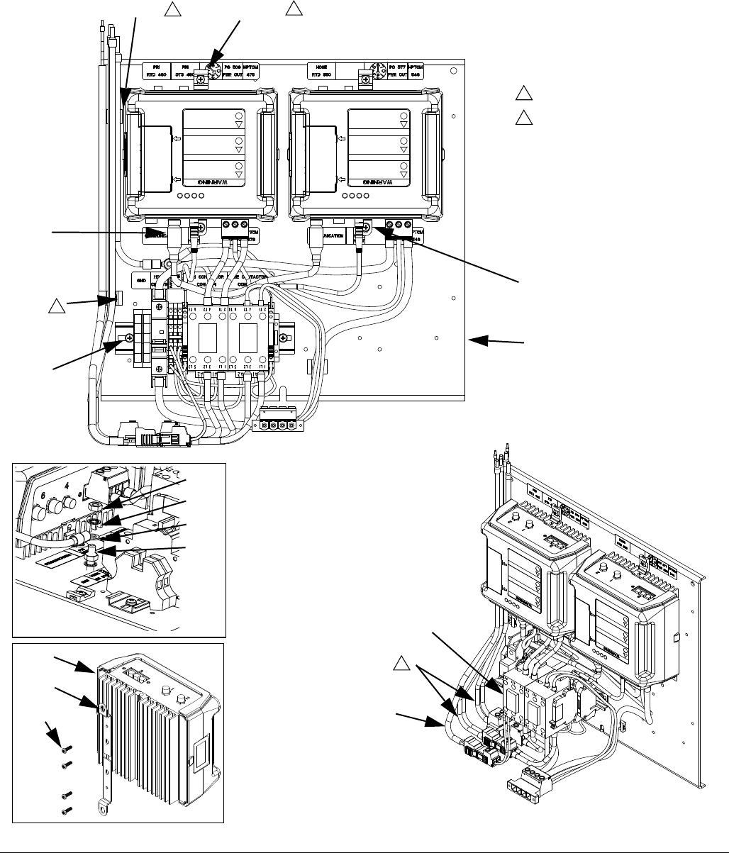
Parts
313998S 65
Heater Sub-Assemblies
Heat Power Panel Module
FIG. 22: Heat Power Panel Modules
1004, 10061004, 1006
1007
1004,
1005,
1001
1005, 1006
1003
1014
1012
24C332_313998_8f
1010
1009
1011
1008
1006
1006
1002
1015
1016
Tie wires at this point.
Torque connector screws to 16 in-lb
(1.8 N•m).
1
2
1
1
1
2
24C332_313998_3f
24C332_313998_1f
24C332_313998_7f
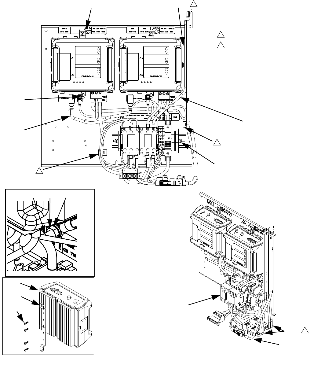
Parts
66 313998S
FIG. 23: Heat Power Panel Modules
1005, 1006 1004, 1006
1007
1004,
1004,
1004, 1006
1011
1003
1014
1012
1006
1006
1002
1015
1016
100910101008
Tie wires at this point.
Torque connector screws to 16 in-lb
(1.8 N•m).
1
2
1
1
1
1005, 1006
2
24C332_313998_6f
24C332_313998_4f
24C332_313998_4f
24C332_313998_7f

Parts
313998S 67
Ref Part Description
Quantity
MODULE, panel,
pwr, heat, hose, pr, hv
MODULE, panel,
pwr, heat, hose, hv
MODULE, panel,
pwr, heat, pri, hv
MODULE, panel,
pwr, no heat, hv
MODULE, panel,
pwr, heat, hose, pr, lv
MODULE, panel,
pwr, heat, hose, lv
MODULE, panel,
pwr, heat, pri, lv
MODULE, panel,
pwr, no heat, lv
1001 PANEL, electric, heat 1 1 1 1 1 1 1 1
1002 255774 MODULE, high power temp, gca 2 1 1 2 1 1
1003 MODULE, assy, pwr, heat, hose, pri, hv 1
MODULE, assy, pwr, heat, hose, hv 1
MODULE, assy, pwr, heat, pri, hv 1
MODULE, assy, pwr, no heat, hv 1
MODULE, assy, pwr, heat, hose, pri, lv 1
MODULE, assy, pwr, heat, hose, lv 1
MODULE, assy, pwr, heat, pri, lv 1
MODULE, assy, pwr, no heat, lv 1
1004 123452 HOLDER, anchor, wire tie, nylon 5 5 4 4 5 5 4 4
1005 116876 WASHER, flat 4 3 3 2 4 3 3 2
1006 103833 SCREW, mach, crbh (matrix) 9 8 7 6 9 8 7 6
1007 125306 CABLE, can, female / female 0.5m 1 1
1008 100021 SCREW, cap hex hd (matrix) 1 1 1 1 1 1 1 1
1009 100028 WASHER, lock 2 2 2 2 2 2 2 2
1010 100015 NUT, hex mscr 2 2 2 2 2 2 2 2
1011 24C311 HARNESS, wire, pdb, ground 1 1 1 1 1 1 1 1
1012 24C318 HARNESS, wire, pdb, terminal 1 1 1 1 1 1 1 1
1014 24C304 HARNESS, wire, pdb, inline heater 2 1 1 2 1 1
1015 15R535 BRACKET, mounting, GCA high power 4 2 2 4 2 2
1016 117831 SCREW, mach., pan hd (matrix) 8 4 4 8 4 4
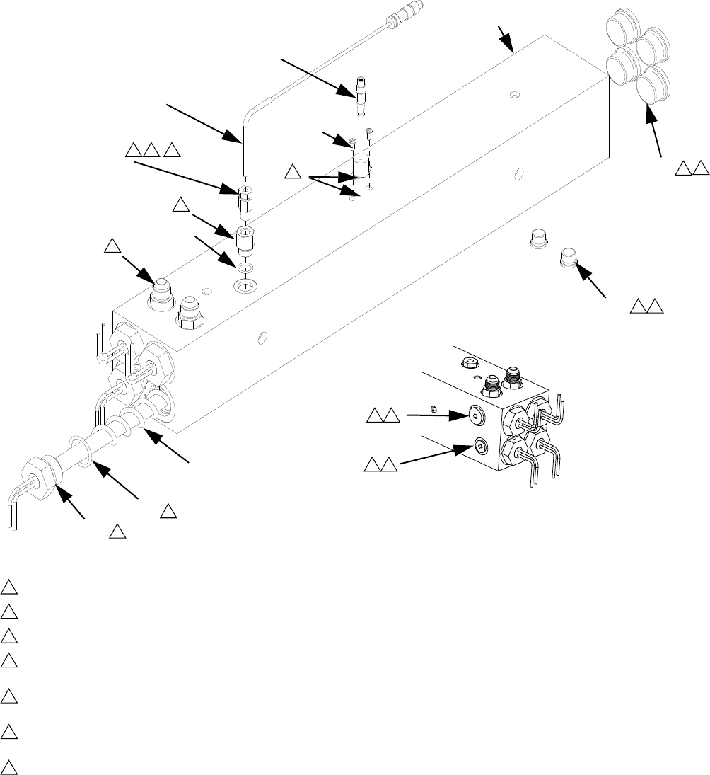
Parts
68 313998S
Heater - Aluminum with Carbon Steel Fittings, 24C426
Heater - Aluminum with Stainless Steel Fittings, 24P165
1106
1104
1103
1105
1105
1102
1107
1108
Torque to 120 ft-lb (163 N•m)
Torque to 23 ft-lb (31 N•m)
Torque to 40 ft-lb (54 N•m)
Apply lubricant to o-rings before assembling into
heater.
Tighten NPT thread at least on turn after RTD
has been tightened.
Apply thermal paste when assembling thermal
switch.
Apply sealant and tape to all non swiveling and
non o-ring threads.
1
2
3
4
6
8
9
14
2 4
4
1
1101
r_24p165
1109
1110
1111
1112
1113
4
4
8
9 6 2
4 3
2 4
1106a
r_24c106_313998_2
24P165 Shown

Parts
313998S 69
--- Not available for individual sale.
◆Item 1106 include fluoroelastomer o-ring.
Ref
Part
Description Qty
Assembly
24C426
Assembly
24P165
1101 15J090 15J090 HEATER, machined, 1 zone, 3500 psi 1
1102 124132 124132 O-RING 4
1103 15H305 126561 FITTING, plug hollow hex 1-3/16 sae 4
1104 121309 126562 FITTING, adapter, sae-orb x jic 2
1105 15H304 126563 FITTING, plug 9/16 sae 3
1106 15H306 126564◆ADAPTER, thermocouple, 9/16 x 1/8 1
1106a 120336 ◆O-RING, packing 1
1107 15B135 16T320 MIXER, immersion heater 4
1108 16A112 16A112 HEATER, immersion (1500W 230V) 4
1109 295607 561460 PLUG, outlet 1
1110 123325 FITTING, compression, 1/8npt, ss 1
1111 124262 SENSOR, rtd, 1kohm, 90deg, 4pin, tip 1
1112 123408 HARNESS, m8 x thermal switch, 3-pin 1
1113 100518 SCREW, mach, mnhd 2
1115 --- LUBRICANT, thermal 1
1116 --- --- TAPE, tfe, sealant 1
1117 --- --- LUBRICANT, thread 1
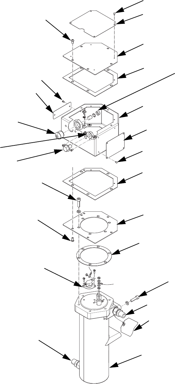
Parts
70 313998S
Heater 24J787
ti17875a
1401
1433
1412
1410
1402
1403
1404
1409
1434
1405
1404
1406
1407
1408
1409
1435
1410
1408
1429
1412
1430
1431
1411
1423
1421
1426
1416
1422
1427
1428
1417
1418
1419
1420
1409
Parts
313998S 71
▲Replacement Danger and Warning labels, tags and
cards are available at no cost.
--- Not for individual sale
† Items available for purchase in kit 24K290
Ref Part Description Qty
1401† --- BLOCK, heater, machined 1
1402 15A990 GASKET, heater 1
1403 15A811 COVER, heater controls, bottom 1
1404 15A991 GASKET, heater 2
1405 15A809 ENCLOSURE, controls, heater 1
1406 15A810 COVER, heater controls, top 1
1407 15B625 LABEL, plate, warning 1
1408 111962 SCREW, cap, button hd 10
1409 100055 SCREW, drive, #6 10
1410 107542 WASHER, lock, spring 10
1411 117367 SCREW, shcs, m8x18 6
1412† 117344 FITTING, tube, compression 2
1413▲172953 LABEL, designation 1
1414 111307 WASHER, lock, external 1
1415 116343 SCREW, ground 1
1416 15B828 HOUSING, light, heater, viscon hp 1
1417 106216 NUT, lock 1
1418 15B827 LENS, light, glass 1
1419 103338 PACKING, o-ring 1
1420 117483 SCREW, jam, socket 1
1421 111802 SCREW, cap, hex hd 1
1422 112731 NUT, hex, flanged 1
1423 109114 SCREW, cap, sch 4
1424 100166 NUT, full hex 4
1425 102360 WASHER, flat 4
1426 15U075 SCREW, cap, bh, 8-32 x .37 2
1427 555388 NUT, # 8-32 hex 2
1428 100079 WASHER, lock, spring 2
1429 108674 THERMOSTAT 1
1430 105676 SCREW, mach, pnh 2
1431 073019 LUBRICANT, thermal 1
1432 235524 WIRE, assy 1
1433▲177922 TAG, warning 1
1434▲16K138 LABEL, brand, viscon hp, nvh 1
1435▲15B623 LABEL, plate, des, viscon hp 1
1442▲15B777 LABEL, warning, viscon hp 1
1443▲15B819 LABEL, warning, viscon hp 1
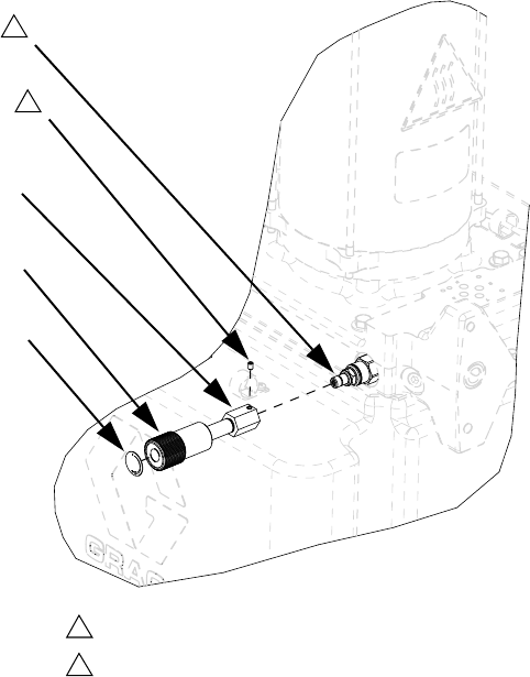
Kits
72 313998S
Kits
DC Power Pack Pressure Adjustment Kit, 24C067
This kit provides a release for excess pressure in the hydraulic system. It must be installed if a Fusion or P2 gun is
used.
Ref Part Description Qty
1201 15H204 KNOB, pressure adjustment 1
1202 15H512 LABEL, control, H25 1
1203 15Y370 ADAPTER, pressure relief 1
1204 116624 SCREW, set, socket head 1
Torque to 23 in-lb (2.6 N•m).
Part is reference number 15 in hydraulic power
pack assembly. See Hydraulic DC Power Pack
Module on page 54.
4
5
1204
1203
1201
1202
2
1

Kits
313998S 73
DC Power Pack Hydraulic
Pressure Adjustment Setup
This kit provides a release for excess pressure in the
hydraulic system. It must be installed if a Fusion or P2
gun is used.
1. Perform Shutdown on page 21.
2. Remove Hydraulic Power Pack Shroud, page 33.
3. Install pressure relief kit 24C067.
NOTE: Prior to installing pressure adjustment
knob (1201), use a 9/16 in. wrench to back the jam
nut (1203) all the way out until it stops.
4. Turn the pressure adjustment knob (1201) clock-
wise until it stops.
5. Turn the pressure adjustment knob counter-clock-
wise two full turns.
6. Turn main power switch to ON position.
7. Setup the machine to spray in Operator mode. See
HFR operation manual 313997 if necessary.
8. While watching the ADM and listening to the motor,
begin spraying material.
NOTE: If the ADM displays an overpressure situation,
the relief pressure is set too high.
NOTE: If it sounds like the motor is spinning too fast
and/or it sounds like hydraulic fluid is being dumped
back to the tank, the relief pressure is set too low.
9. If the relief pressure is set too high: Clear the
over pressure warning on the ADM then turn the
pressure adjustment knob counterclockwise 1/4
turn. See HFR operation manual 313997 if neces-
sary.
If the relief pressure is set too low: Turn the pres-
sure adjustment knob clockwise 1/4 turn.
10. Repeat the previous two steps until the relief pres-
sure is correctly set.
This procedure requires running the machine with the
hydraulic power pack shroud removed. Be sure to
avoid contact with the fan while the machine is on.
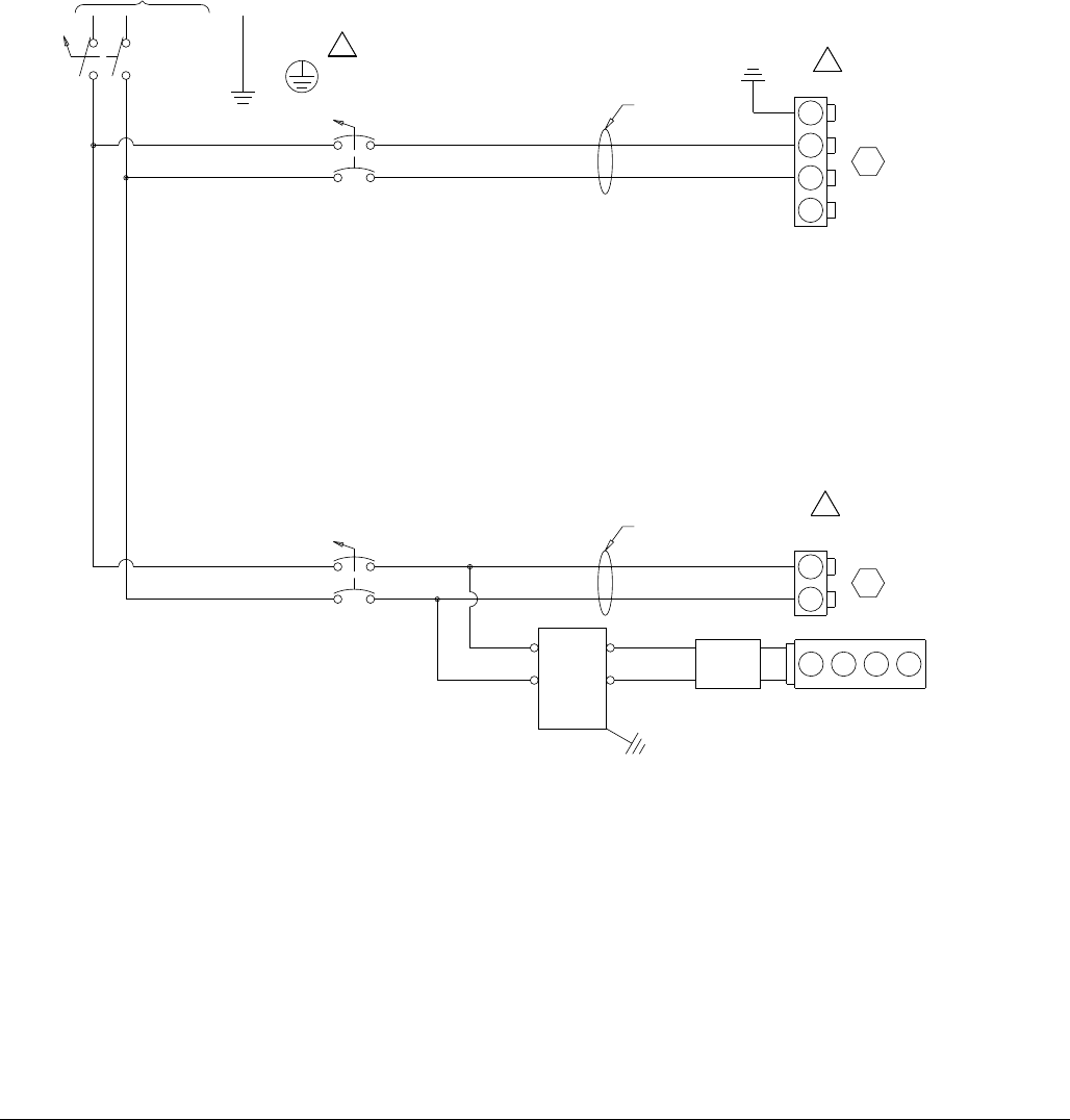
Logic Drawings
74 313998S
Logic Drawings
230V, 1 Phase, No Heat
FIG. 24: 230V, 1 Phase, No Heat Logic Drawing; Page 1 of 1
140
149
147
145
142
110
138
136
134
132
130
128
126
124
122
120
118
114
116
112
108
106
104
102
100
141
148
144
146
143
111
139
137
135
133
131
129
127
125
123
121
119
115
117
113
109
107
105
103
101
190
199
197
195
192
160
188
186
184
182
180
178
176
174
172
170
168
164
166
162
158
156
154
152
150
191
198
194
196
193
161
189
187
185
183
181
179
177
175
173
171
169
165
167
163
159
157
155
153
151
50-60HZ
1PH/
230V/
DISC-1
L21L2
L11L1
GND
1L1
MISC
B VOLUME
CB5
1L1
1L2
1L2
PG133
755
1L1
CB1A
1L1
1L21L2
HARNESS
24C515
HARNESS
24C318
63A
5A
1340
1360
1340
1360
MCM
B VOLUME
PG105
1080
1100
331
GND
L1
GND
L2
L3
1080
1100
1360
1340
1340
1360
POWER
SUPPLY
121808 123466
CAN SPLITTER
GND
POWER
FILTER
L1/P
L2/N
LOAD
LINE
1390 BR
1400 BL
LOCATED IN THE MAIN PDB ENCLOSURE
CUSTOMER MUST SUPPLY BRANCH CIRCUIT PROTECTION
1
1
1
BLK
WHT
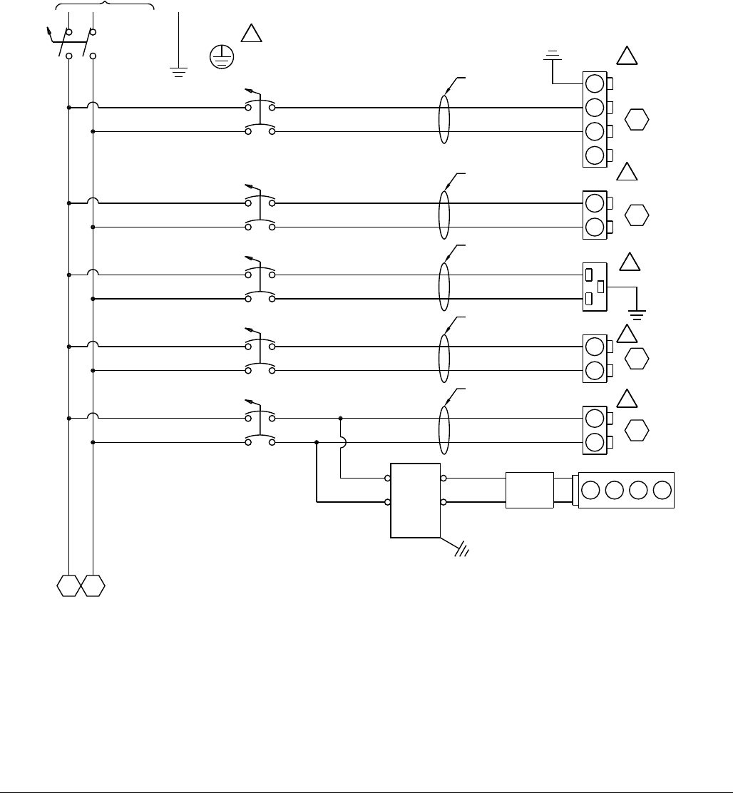
Logic Drawings
313998S 75
230V, 1 Phase, with Heat
FIG. 25: 230V, 1 Phase, with Heat Logic Drawing; Page 1 of 2
140
149
147
145
142
110
138
136
134
132
130
128
126
124
122
120
118
114
116
112
108
106
104
102
100
141
148
144
146
143
111
139
137
135
133
131
129
127
125
123
121
119
115
117
113
109
107
105
103
101
50-60HZ
1PH/
230V/
DISC-1
L21L2
L11L1
GND
1L1
CB1A
1L1
1L2
1L2
HARNESS
24C515
63A
151
1L2
TANK
B VOLUME
CB3
PG121
GND
PRIMARY HT
B VOLUME
CB2
PG116
511
HOSE HT
B VOLUME
CB4
PG127
580
MISC
B VOLUME
CB5
PG133
755
HARNESS
24C303
HARNESS
24C304
HARNESS
24C318
40A
15A
40A
5A
151
1L1
1L1
1L1
1L2
1L2
1L11L1
1L2
1L2
1L11L1
1L2
1L2
1L11L1
1L2
1L2
1220
1240
1220
1240
1160
1180
1160
1180
1280
1300
1280
1300
1340
1360
1340
1360
MCM
B VOLUME
PG105
1080
1100
331
GND
L1
GND
L2
L3
HARNESS
24C517
1080
1100
1360
1340
1340
1360
POWER
SUPPLY
121808 123466
CAN SPLITTER
GND
POWER
FILTER
L1/P
L2/N
LOAD
LINE
1390 BR
1400 BL
LOCATED IN THE MAIN PDB ENCLOSURE
CUSTOMER MUST SUPPLY BRANCH CIRCUIT PROTECTION
1
1
1
1
1
1
BLK
WHT
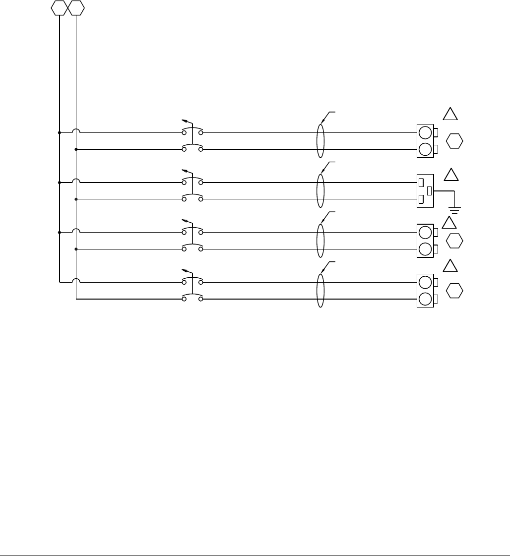
Logic Drawings
76 313998S
FIG. 26: 230V, 1 Phase, with Heat Logic Drawing; Page 2 of 2
190
199
197
195
192
160
188
186
184
182
180
178
176
174
172
170
168
164
166
162
158
156
154
152
150
191
198
194
196
193
161
189
187
185
183
181
179
177
175
173
171
169
165
167
163
159
157
155
153
151
148
1L2
TANK
A VOLUME
CB8
PG172
GND
PRIMARY HT
A VOLUME
CB9
PG166
649
HOSE HT
A VOLUME
CB7
PG178
718
HARNESS
24C303
HARNESS
24C304
40A
15A
40A
148
1L1
1L1
1L1
1L2
1L2
1L11L1
1L2
1L2
1L11L1
1L2
1L2
1720
1740
1720
1740
1660
1680
1660
1680
1780
1800
1780
1800
HARNESS
24C517
MISC
A VOLUME
CB6
PG184
824
HARNESS
24C318
5A
1L2
1L2
1840
1860
1840
1860
1L1
1L1
2
2
2
2
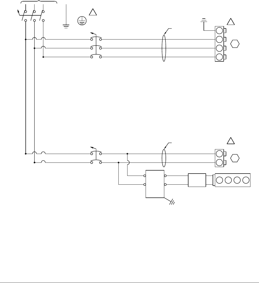
Logic Drawings
313998S 77
230V, 3 Phase, No Heat
FIG. 27: 230V, 3 Phase, No Heat Logic Drawing; Page 1 of 1
140
149
147
145
142
110
138
136
134
132
130
128
126
124
122
120
118
114
116
112
108
106
104
102
100
141
148
144
146
143
111
139
137
135
133
131
129
127
125
123
121
119
115
117
113
109
107
105
103
101
50-60HZ
3PH/
230V/
DISC-1
L31L3
L21L2
L11L1
GND
1L1
MISC
B VOLUME
CB5
1L1
1L21L2
PG133
755
1L1
CB1
1L1
1L21L2
HARNESS
24C516
HARNESS
24C318
30A
5A
1L31L3
1340
1360
1340
1360
MCM
B VOLUME
PG105
1080
1100
331
GND
L1
GND
L2
L3
1120
1080
1100
1120
1360
1340
1340
1360
POWER
SUPPLY
121808 123466
CAN SPLITTER
GND
POWER
FILTER
L1/P
L2/N
LOAD
LINE
1390 BR
1400 BL
LOCATED IN THE MAIN PDB ENCLOSURE
CUSTOMER MUST SUPPLY BRANCH CIRCUIT PROTECTION
1
1
1
BLK
RED
WHT
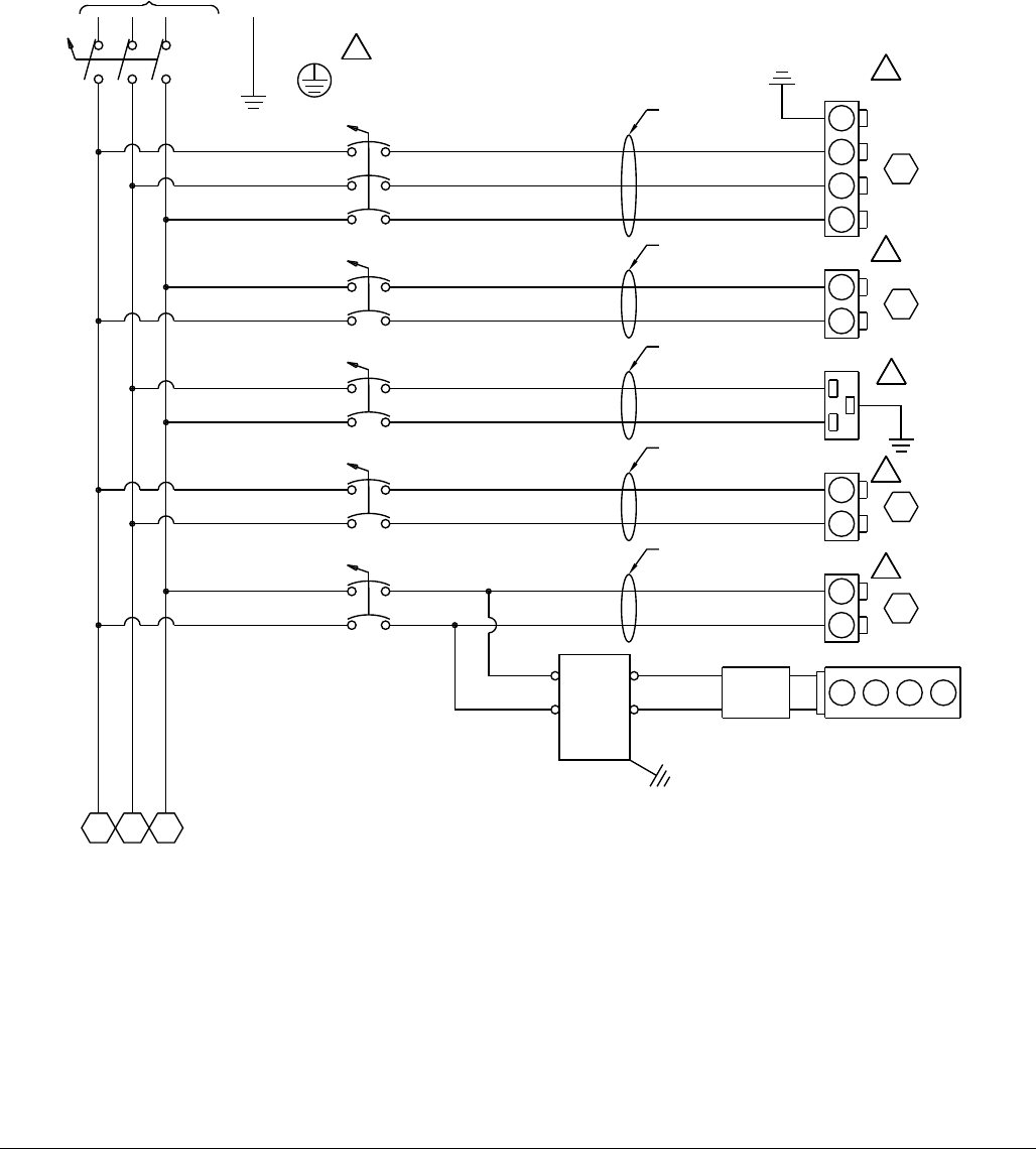
Logic Drawings
78 313998S
230V, 3 Phase, with Heat
FIG. 28: 230V, 3 Phase, with Heat Logic Drawing; Page 1 of 2
140
149
147
145
142
110
138
136
134
132
130
128
126
124
122
120
118
114
116
112
108
106
104
102
100
141
148
144
146
143
111
139
137
135
133
131
129
127
125
123
121
119
115
117
113
109
107
105
103
101
50-60HZ
3PH/
230V/
DISC-1
L31L3
L21L2
L11L1
GND
151
1L3
151
1L2
TANK
B VOLUME
CB3
PG121
GND
PRIMARY HT
B VOLUME
CB2
PG116
511
HOSE HT
B VOLUME
CB4
PG127
580
MISC
B VOLUME
CB5
PG133
755
HARNESS
24C303
HARNESS
24C304
HARNESS
24C516
HARNESS
24C318
40A
15A
40A
5A
1L11L1
1L21L2
151
1L1
1L31L3
CB1
30A
1L31L3
1L11L1
1L31L3
1L21L2
1L11L1
1L21L2
1L31L3
1L11L1
1220
1240
1220
1240
1160
1180
1160
1180
1280
1300
1280
1300
1340
1360
1340
1360
MCM
B VOLUME
PG105
1080
1100
331
GND
L1
GND
L2
L3
1120
HARNESS
24C517
1080
1100
1120
1360
1340
1340
1360
POWER
SUPPLY
121808 123466
CAN SPLITTER
GND
POWER
FILTER
L1/P
L2/N
LOAD
LINE
1390 BR
1400 BL
LOCATED IN THE MAIN PDB ENCLOSURE
CUSTOMER MUST SUPPLY BRANCH CIRCUIT PROTECTION
1
1
1
1
1
1
BLK
RED
WHT
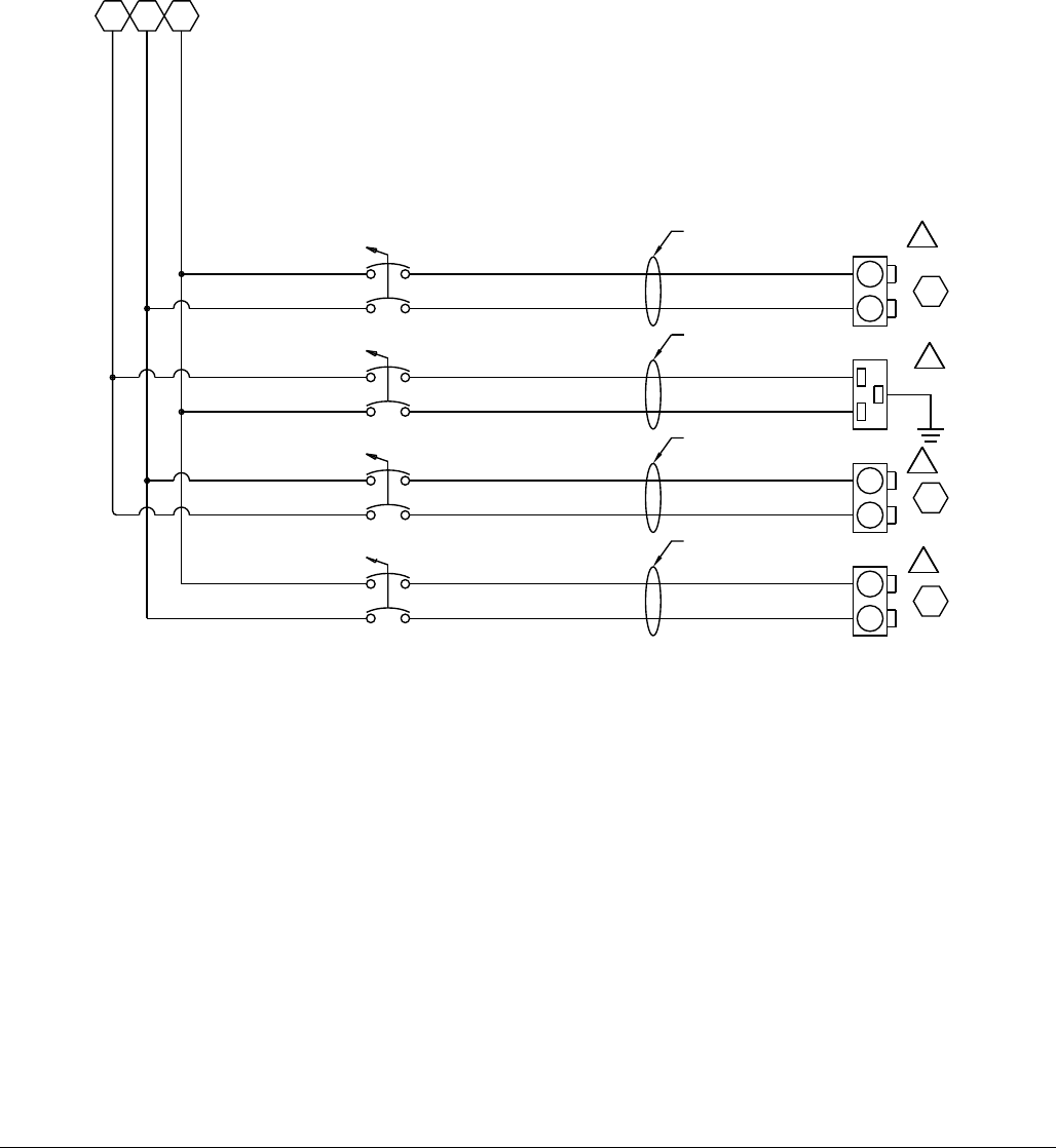
Logic Drawings
313998S 79
FIG. 29: 230V, 3 Phase, with Heat Logic Drawing; Page 2 of 2
190
199
197
195
192
160
188
186
184
182
180
178
176
174
172
170
168
164
166
162
158
156
154
152
150
191
198
194
196
193
161
189
187
185
183
181
179
177
175
173
171
169
165
167
163
159
157
155
153
151
148
1L3
148
1L2
TANK
A VOLUME
CB8
PG172
GND
PRIMARY HT
A VOLUME
CB9
PG166
649
HOSE HT
A VOLUME
CB7
PG178
718
HARNESS
24C303
HARNESS
24C304
HARNESS
24C318
40A
15A
40A
148
1L1
30A
1L3
1L1
1L1
1L2
1L2
1L31L3
1L1
1L1
1L21L2
1L31L3
1720
1740
1720
1740
1660
1680
1660
1680
1780
1800
1780
1800
HARNESS
24C517
MISC
A VOLUME
CB6
PG184
824
HARNESS
24C318
5A
1L2
1L2
1L3
1L3 1840
1860
1840
1860
2
2
2
2
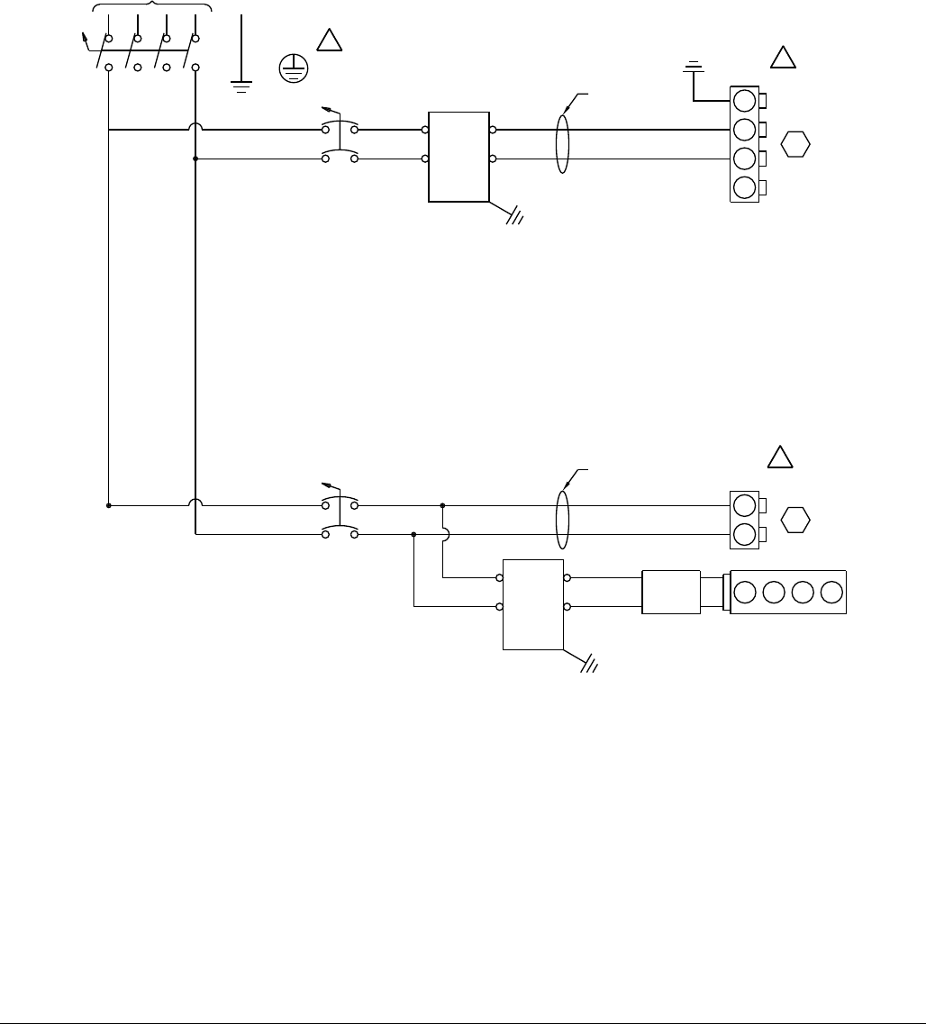
Logic Drawings
80 313998S
400V, 3 Phase, No Heat
FIG. 30: 400V, 3 Phase, No Heat Logic Drawing; Page 1 of 1
140
149
147
145
142
110
138
136
134
132
130
128
126
124
122
120
118
114
116
112
108
106
104
102
100
141
148
144
146
143
111
139
137
135
133
131
129
127
125
123
121
119
115
117
113
109
107
105
103
101
50-60HZ
3PH/
400V/
DISC-1
L31L3
L21L2
L11L1
N1N
GND
MISC
B VOLUME
CB5
1N1N
PG133
755
1L1
CB1A
1L1
1N1N
HARNESS
24C515
HARNESS
24C318
63A
5A
1340
1360
1340
1360
MCM
B VOLUME
PG105
1080
1100
331
GND
L1
GND
L2
L3
1081
1101
GND
POWER
FILTER
L1/P
L2/N
LOAD
LINE
1080
1100
1360
1340
1340
1360
POWER
SUPPLY
121808 123466
CAN SPLITTER
GND
POWER
FILTER
L1/P
L2/N
LOAD
LINE
1390 BR
1400 BL
LOCATED IN THE MAIN PDB ENCLOSURE
CUSTOMER MUST SUPPLY BRANCH CIRCUIT PROTECTION
1L1 1L1
1
1
1
BLK
WHT
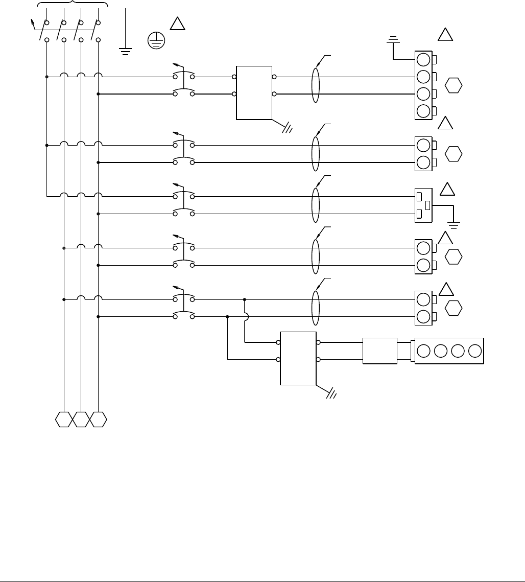
Logic Drawings
313998S 81
400V, 3 Phase, with Heat
FIG. 31: 400V, 3 Phase, with Heat Logic Drawing; Page 1 of 2
140
149
147
145
142
110
138
136
134
132
130
128
126
124
122
120
118
114
116
112
108
106
104
102
100
141
148
144
146
143
111
139
137
135
133
131
129
127
125
123
121
119
115
117
113
109
107
105
103
101
151
50-60HZ
3PH/
400V/
DISC-1
L31L3
L21L2
L11L1
N1N
GND
1N
151
1L3
151
1L2
1L1
TANK
B VOLUME
CB3
1L1 1220
1N1N 1240
PG121
GND
1220
1240
1L1
PRIMARY HT
B VOLUME
CB2
1L1 1160
1N1N 1180
PG116
1160
1180
511
1L2
HOSE HT
B VOLUME
CB4
1L2 1280
1N1N 1300
PG127
1280
1300
580
1L2
MISC
B VOLUME
CB5
1L2 1340
1N1N 1360
PG133
1340
1360
755
1L1
MCM
B VOLUME
CB1A
1L1
1N1N
PG105
1080
1100
331
GND
HARNESS
24C303
HARNESS
24C304
HARNESS
24C515
HARNESS
24C318
40A
63A
15A
40A
5A
L1
GND
L2
L3
HARNESS
24C517
1081
1101
GND
POWER
FILTER
L1/P
L2/N
LOAD
LINE
1080
1100
1360
1340
1340
1360
POWER
SUPPLY
121808 123466
CAN SPLITTER
GND
POWER
FILTER
L1/P
L2/N
LOAD
LINE
1390 BR
1400 BL
LOCATED IN THE MAIN PDB ENCLOSURE
CUSTOMER MUST SUPPLY BRANCH CIRCUIT PROTECTION
1
1
1
1
1
1
BLK
WHT
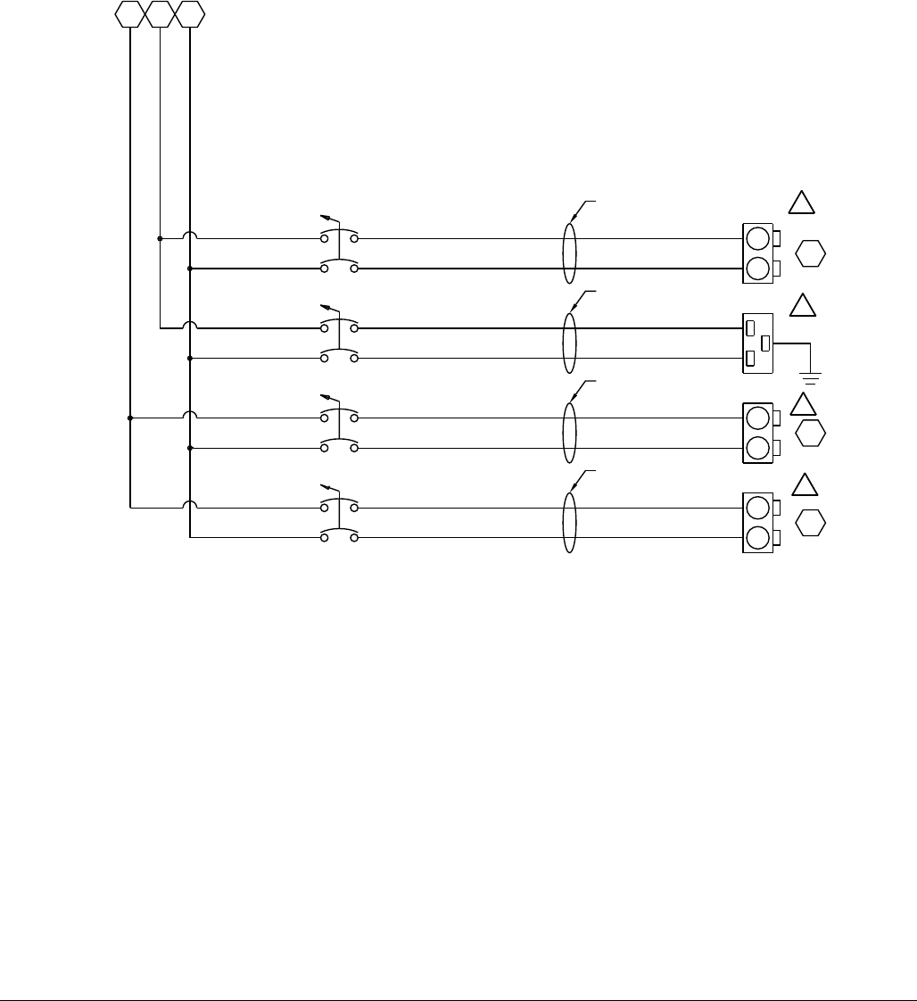
Logic Drawings
82 313998S
FIG. 32: 400V, 3 Phase, with Heat Logic Drawing; Page 2 of 2
190
199
197
195
192
160
188
186
184
182
180
178
176
174
172
170
168
164
166
162
158
156
154
152
150
191
198
194
196
193
161
189
187
185
183
181
179
177
175
173
171
169
165
167
163
159
157
155
153
151
148
1N
148
1L3
148
1L2
1L3
TANK
A VOLUME
CB8
1720
1N1N 1740
PG172
GND
1720
1740
1L3
PRIMARY HT
A VOLUME
CB9
1660
1N1N 1680
PG166
1660
1680
649
1L2
HOSE HT
A VOLUME
CB7
1L2 1780
1N1N 1800
PG178
1780
1800
718
HARNESS
24C303
HARNESS
24C304
40A
15A
40A
1L3
1L3
HARNESS
24C517
1L2
MISC
A VOLUME
CB6
1840
1N
1N 1860
PG184
1840
1860
824
HARNESS
24C318
5A
2
2
2
2
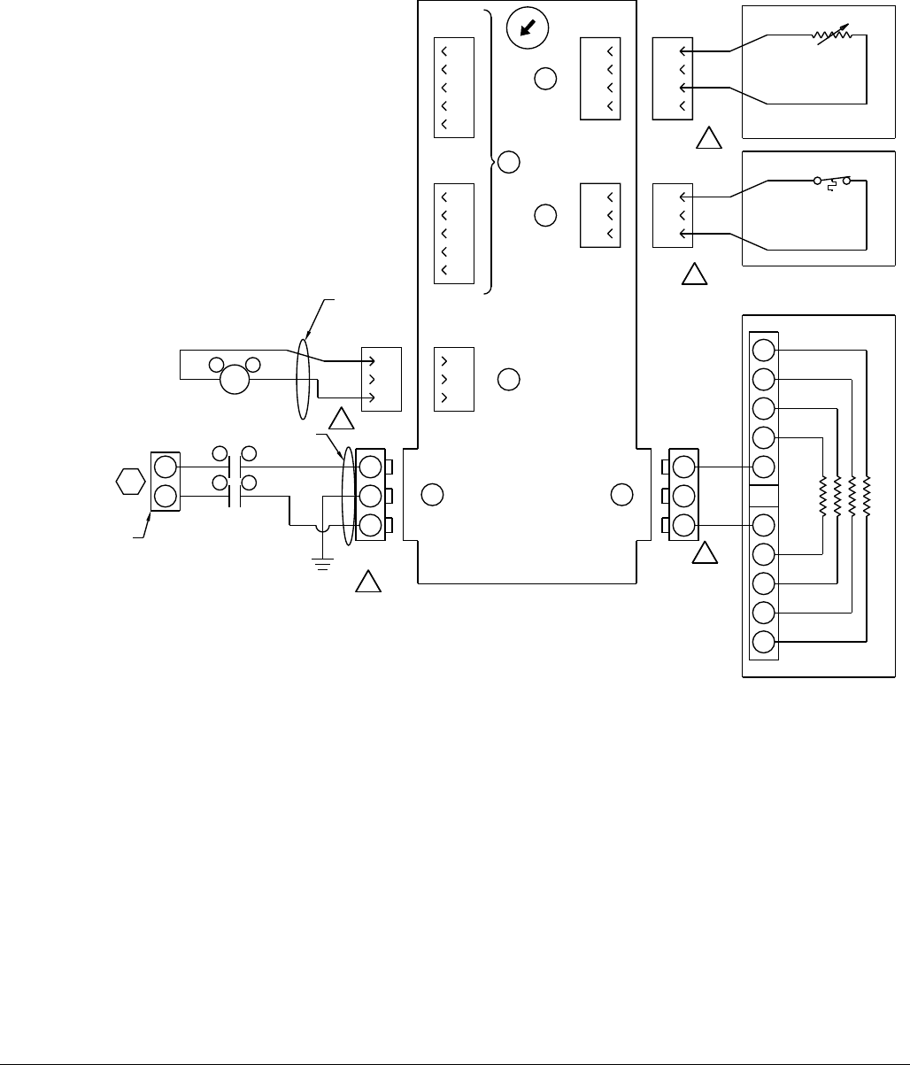
Logic Drawings
313998S 83
A (Red) Heat
FIG. 33: A (Red) Heat Logic Drawing, Page 1 of 2
M8 3 PIN
FEMALE
3
4
1
M12 5 PIN
MALE
5
4
3
2
1
CAN COMM PORT
M12 5 PIN
MALE
5
4
3
2
1
CAN COMM PORT
4
6
HPTCM PRIMARY LOW VOLUME
3
4
1
1
M8 3 PIN
FEMALE
4
3
2
1
2
M8 4 PIN
FEMALE
4
3
2
1
M8 4 PIN
MALE
RTD618
PRIMARY TEMP
EXC
SIGNAL
3
4
1
M8 3 PIN
MALE
EXC
SIGNAL
OTS628
PRIMARY TEMP
CR642
A1+ A2-
3
4
1
M8 3 PIN
MALE
HARNESS
16A522
+24VDC
SIGNAL
6420
GND 3
GND
5
PRIMARY HT
LOW VOLUME
PG166
167
34
CON863
12
HARNESS
24C267
6400
1660
1680
DB-1
6480
6520
PRIMARY HEATER
SEE CONFIGURATION
654
663
661
659
656
624
652
650
648
646
644
642
640
638
636
634
632
628
630
626
622
620
618
616
614
655
662
658
660
657
625
653
651
649
647
645
643
641
639
637
635
633
629
631
627
623
621
619
617
615
674
681
679
676
672
670
668
664
675
682
678
680
677
673
671
669
665
666
667
6490
6500
PG646 PG647
VR 24C313
FR 24C312
HARNESS
6480
6480
6480
6480
6520
6520
6520
6520
BLU
BRN
HARNESS
24C265
6
2
4
0
7
5
3
1
A - RED
LOCATED IN THE MAIN
SUPPORT ENCLOSURE
1
2
4
53
2
2
2
2
2
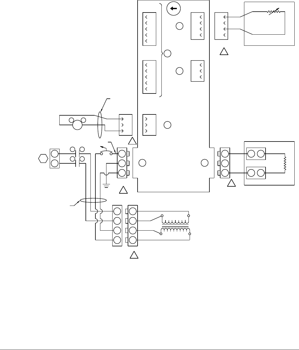
Logic Drawings
84 313998S
FIG. 34: A (Red) Heat Logic Drawing, Page 2 of 2
725
735
733
731
727
695
723
721
719
717
715
713
711
709
707
705
703
699
701
697
693
691
689
687
685
726
734
729
732
728
696
724
722
720
718
716
714
712
710
708
706
704
700
702
698
694
692
690
688
686
744
751
749
746
742
740
738
736
745
748
750
747
743
741
739
737
M8 3 PIN
FEMALE
3
4
1
M12 5 PIN
MALE
5
4
3
2
1
CAN COMM PORT
M12 5 PIN
MALE
5
4
3
2
1
CAN COMM PORT
4
6
HPTCM HOSE LOW VOLUME
3
4
1
1
M8 3 PIN
FEMALE
4
3
2
1
2
M8 4 PIN
FEMALE
4
3
2
1
M8 4 PIN
MALE
RTD688
HOSE TEMP
EXC
SIGNAL
CR711
A1+ A2-
3
4
1
M8 3 PIN
MALE
HARNESS
16A522
+24VDC
SIGNAL
7110
GND 3
GND
5
HOSE HT
LOW VOLUME
PG178
179
34
CON-869
12
7090
1780
1800
7172
7210
HOSE HEATER
SEE CONFIGURATION
CB718
TRANS1
SECONDARY
PRIMARY
7290
7310
7330
7350
PG728
730
683
684
BLU
BRN
7170
7310
7290
7350
7330
HARNESS
24C274
PG715
24C418
VR 24C315
FR 24C314
HARNESS
PG716
6
2
4
0
7
5
3
1
A - RED
LOCATED IN THE MAIN
SUPPORT ENCLOSURE
2
4
53
2
2
2
2
2
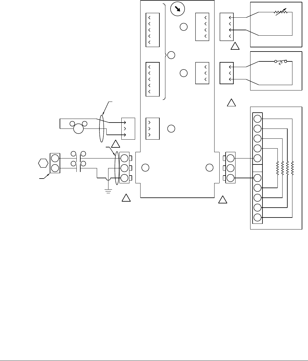
Logic Drawings
313998S 85
B (Blue) Heat
FIG. 35: B (Blue) Heat Logic Drawing, Page 1 of 2
M8 3 PIN
FEMALE
3
4
1
M12 5 PIN
MALE
5
4
3
2
1
CAN COMM PORT
M12 5 PIN
MALE
5
4
3
2
1
CAN COMM PORT
4
6
HPTCM PRIMARY HI VOLUME
3
4
1
1
M8 3 PIN
FEMALE
4
3
2
1
2
M8 4 PIN
FEMALE
4
3
2
1
M8 4 PIN
MALE
RTD480
PRIMARY TEMP
EXC
SIGNAL
3
4
1
M8 3 PIN
MALE
EXC
SIGNAL
OTS490
PRIMARY TEMP
CR504
A1+ A2-
3
4
1
M8 3 PIN
MALE
HARNESS
16A522
+24VDC
SIGNAL
5040
GND 3
GND
5
PRIMARY HT
HI VOLUME
PG116
117
34
CON794
12
HARNESS
24C267
5020
1160
1180
DB-1
5100
5140
PRIMARY HEATER
SEE CONFIGURATION
516
525
523
521
518
486
514
512
510
508
506
504
502
500
498
496
494
490
492
488
484
482
480
478
476
517
524
520
522
519
487
515
513
511
509
507
505
503
501
499
497
495
491
493
489
485
483
481
479
477
534
541
539
536
532
530
528
526
535
542
538
540
537
533
531
529
527
543
544
BLU
BRN
5110
5120
PG509
HARNESS
24C265
5100
5100
5100
5100
5140
5140
5140
5140
PG508
VR 24C313
FR 24C312
HARNESS
6
2
4
0
7
5
3
1
B - BLUE
LOCATED IN THE MAIN
SUPPORT ENCLOSURE
1
2
4
53
1
1
1
11
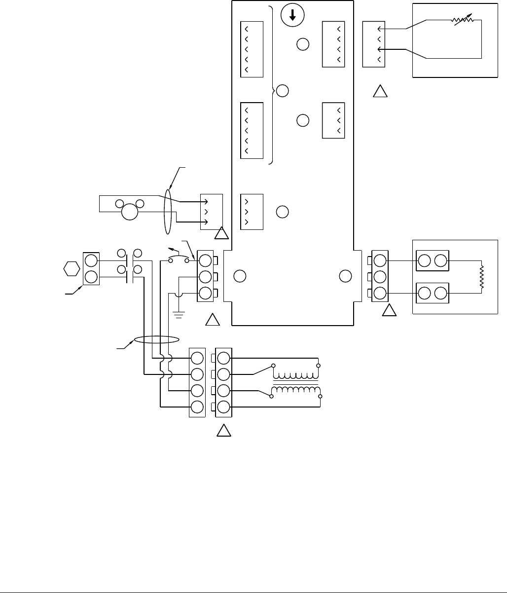
Logic Drawings
86 313998S
FIG. 36: B (Blue) Heat Logic Drawing, Page 2 of 2
585
595
593
591
587
555
583
581
579
577
575
573
571
569
567
565
563
559
561
557
553
551
549
547
545
586
594
589
592
588
556
584
582
580
578
576
574
572
570
568
566
564
560
562
558
554
552
550
548
546
604
611
609
606
602
600
598
596
605
612
608
610
607
603
601
599
597
613
M8 3 PIN
FEMALE
3
4
1
M12 5 PIN
MALE
5
4
3
2
1
CAN COMM PORT
M12 5 PIN
MALE
5
4
3
2
1
CAN COMM PORT
4
6
HPTCM HOSE HI VOLUME
3
4
1
1
M8 3 PIN
FEMALE
4
3
2
1
2
M8 4 PIN
FEMALE
4
3
2
1
M8 4 PIN
MALE
RTD550
HOSE TEMP
EXC
SIGNAL
CR573
A1+ A2-
3
4
1
M8 3 PIN
MALE
HARNESS
16A522
+24VDC
SIGNAL
5730
GND 3
GND
5
HOSE HT
HI VOLUME
PG127
129
34
CON800
12
5710
1280
1300
5792
5830
HOSE HEATER
SEE CONFIGURATION
CB579
TRANS1
SECONDARY
PRIMARY
5910
5930
5950
5970
PG590
590
HARNESS
24C263
BLU
BRN
PG578
5790
5930
5910
5970
5950
HARNESS
24C274
24C418
PG577
VR 24C315
FR 24C314
HARNESS
6
2
4
0
7
5
3
1
B - BLUE
LOCATED IN THE MAIN
SUPPORT ENCLOSURE
2
4
53
1
1
1
1
1
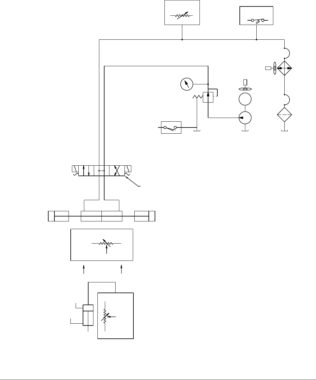
Logic Drawings
313998S 87
DC Hydraulic Power Pack
FIG. 37: DC Hydraulic Power Pack Logic Drawing, Page 1 of 1
930
939
937
935
932
900
928
926
924
922
920
918
916
914
912
910
908
904
906
902
898
896
894
892
890
931
938
934
936
933
901
929
927
925
923
921
919
917
915
913
911
909
905
907
903
899
897
895
893
891
948
955
953
950
946
944
942
940
949
956
952
954
951
947
945
943
941
957
958
TP
BA
AB
PUMP POSITION
+5 VDC GND
SIGNAL
HV LPT280
LV LPT416
HV SOL241
LV SOL378
HV SOL234
LV SOL372
123313
+5 VDC
GND
SIGNAL
M
OIL OVERTEMP
SWITCH
OIL TEMP
RTD OPTIONAL HV OTS264
LV OTS402
FIXED RATIO
MACHINE FRONT
FACING PUMPS
VARIABLE RATIO
VERTICAL PUMP
'B' BLUE
'A' RED
ISO LUBE
PUMP
HV RTD290
LV RTD428
COOLER
FILTER
15J437
HV M310
LV M450
PRESSURE
GAUGE
OPTIONAL
PRESSURE
RELIEF
VALVE
PUMP
HYD. FAN
HV M762
LV M831
MCM FAN
HV M772
LV M841
HYDRAULIC CYLINDER
OIL LEVEL
SENSOR
OPTIONAL
HV PX262
LV PX400
LOCATED ON THE MAIN
HYDRAULIC POWER PACK
A
B
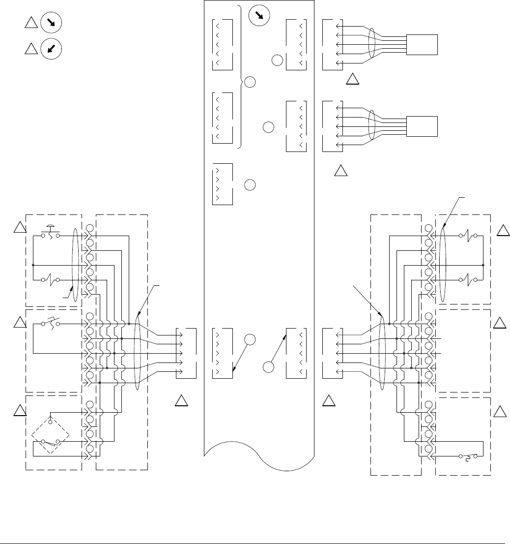
Logic Drawings
88 313998S
Motor Control Module (MCM)
For MCM wiring of Circ Spray Models, see the HFR for Circ Spray Operation manual.
FIG. 38: Motor Control Module (MCM) Logic Drawing, Page 1 of 2
1
240
249
247
245
242
210
238
236
234
232
230
228
226
224
222
220
218
214
216
212
208
206
204
202
200
241
248
244
246
243
211
239
237
235
233
231
229
227
225
223
221
219
215
217
213
209
207
205
203
201
0X
START
PB235
1
2
3
4
5
SOL240
1
2
3
4
5
START
FS247
1
2
3
4
HYD-OIL
LO-LVL
5
4
3
2
1
M12 5 PIN
MALE
M12 5 PIN
FEMALE
5
4
3
2
1
HARNESS
123303
DISPENSE
GUN
M8 4 PIN
FEMALE
4
3
2
1
258
265
263
260
256
254
252
250
259
266
262
264
261
257
255
253
251
267
268
M12 5 PIN
MALE
5
4
3
2
1
CAN COMM PORT
M12 5 PIN
MALE
5
4
3
2
1
CAN COMM PORT
2
10
1
SWITCH POSITION
SHOWN FOR
REF ONLY
4
3
2
1
7
SIGNAL
SIGNAL
COMMON
SIGNAL
SIGNAL
M12 5 PIN
FEMALE
5
SIGNAL
+24VDC
COMMON
SIGNAL
SIGNAL
4
3
2
1
8
M12 5 PIN
FEMALE
5
4
3
2
1
9
M12 5 PIN
FEMALE
5
4
3
2
1
5
M12 5 PIN
MALE
HARNESS
123303
2
3
4
5
1
2
3
4
5
1
2
3
4
4
3
2
1
5
M12 5 PIN
MALE
PRESS XDUCER
BLUE 'B' VOLUME
4
3
2
1
5
M12 5 PIN
MALE
PRESS XDUCER
FIXED RATIO ONLY
RED 'A' VOLUME
B-CODE
B-CODE
SOL234
SOL241
OTS264
OIL TEMP
HI
PX262
121061
+5VDC
-SIG
DC COM
+SIG
SHLD
+5VDC
-SIG
DC COM
+SIG
SHLD
VALVE ASSY
123313
DISPENSE SIGNAL
TO HYDRAULIC
DISP. HEAD FCM
PUMP
LEFT
PUMP
RIGHT
123367
SIGNAL
DC COM
6
2
4
0
7
5
3
1
LOCATED ON THE HYDRAULIC
POWER PACK - FIXED RATIO
2A
2B
2C
7A
7B
7C
27
8
9
6
2
4
0
7
5
3
1
6
2
4
0
7
5
3
1
POS 3 = 3000psi
(DEFAULT)
POS 1 = 2000psi
1
1
1
1
1
1
1 1
1
1
3
3
ss
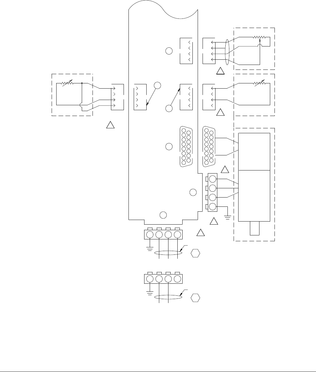
Logic Drawings
313998S 89
FIG. 39: Motor Control Module (MCM) Logic Drawing, Page 2 of 2
BLK
L2
L3
L1
GND
RTD290
4
3
2
1
M8 4 PIN
MALE
M8 4 PIN
FEMALE
4
3
2
1
OIL TEMP
EXC
SIGNAL
310
319
317
315
312
279
308
306
304
302
300
298
296
294
292
290
287
283
285
281
277
275
273
271
269
311
318
314
316
313
280
309
307
305
303
301
299
297
295
293
291
289
284
286
282
278
276
274
272
270
329
336
334
331
326
324
322
320
330
337
333
335
332
328
325
323
321
4
3
2
1
6
M8 4 PIN
FEMALE
L1
GND
L2 L3
GND
1080
1100
1120
12
109
4
3
2
1
M8 4 PIN
FEMALE
13
15
8
13 10
4 1
9
32
1112
6
14
75
11
15 PIN DSUB
FEMALE
4
3
2
1
M8 4 PIN
MALE
4
3
2
1
M8 4 PIN
MALE
15 PIN DSUB
MALE
GND
RED
BLU
3
5
RTD292
MOTOR TEMP
EXC
SIGNAL
PUMP POSITION
EXC
COMMON
SIGNAL
15
8
13 10
4 1
9
32
1112
6
14
75
LPT280
258669
ENCODER
HARNESS
24C516
288
327
MOTOR
PG105
OPTION
L1
GND
L2 L3
GND
1580
1600
HARNESS
24C515
PG105
M310
3 PHASE
1 PHASE
109
3
6
5
11
13
12
SHLD
1
1
1
1
1
1
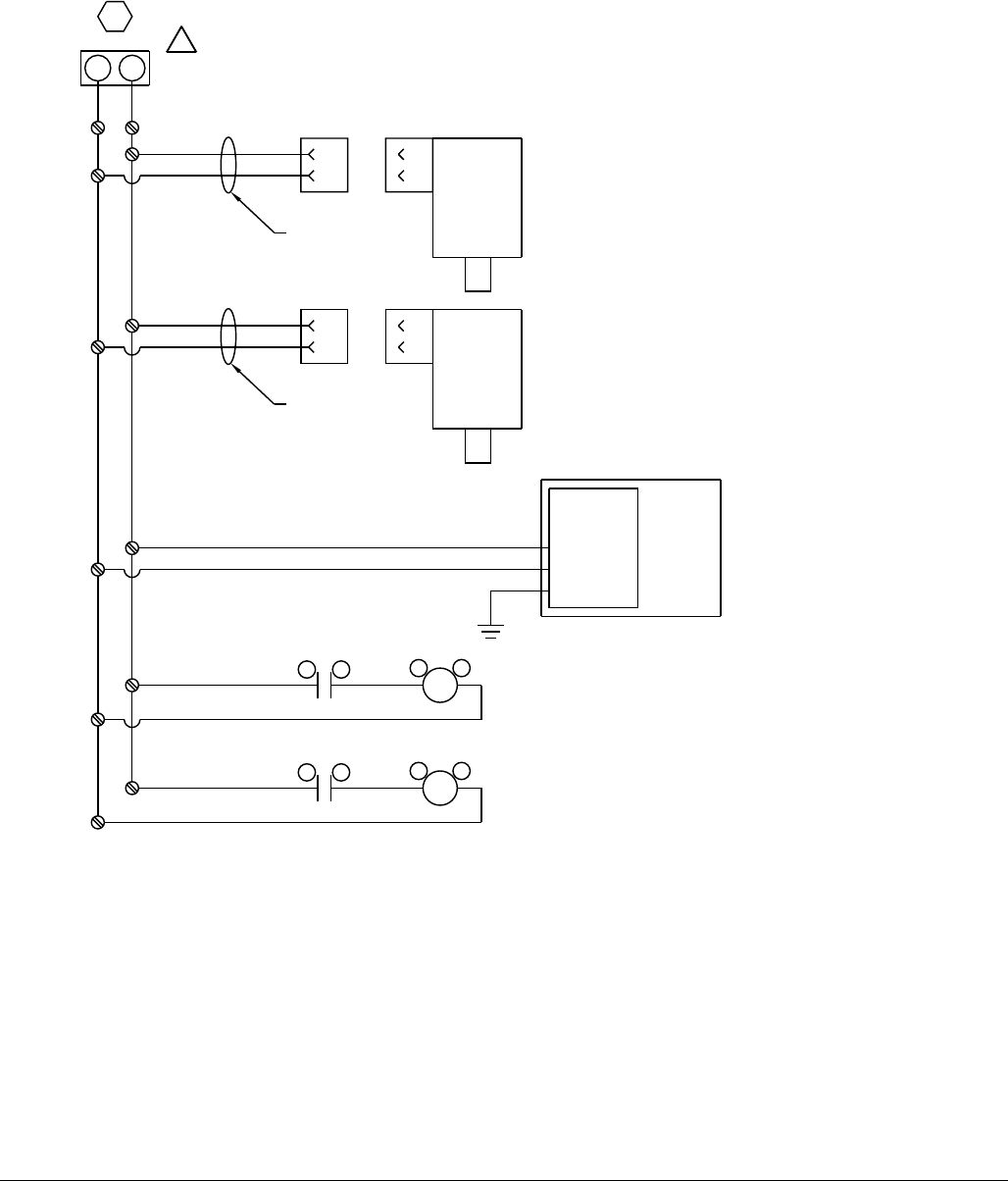
Logic Drawings
90 313998S
Miscellaneous Power
FIG. 40: Miscellaneous Power Logic Drawing, Page 1 of 2
CON794
A1 A2
CR504
11 14
MISC B - BLUE
HI VOLUME
PG133
135
792
801
799
797
794
762
790
788
786
784
782
780
778
776
774
772
770
766
768
764
760
758
756
754
752
793
800
796
798
795
763
791
789
787
785
783
781
779
777
775
773
771
767
769
765
761
759
757
755
753
810
817
815
812
808
806
804
802
811
818
814
816
813
809
807
805
803
819
820
1360
1340
2
1
2
1
MOTOR
FAN
HYD
HEAT
EXCH'R
1340
1360
2
1
2
1
MOTOR
FAN
MCM
HARNESS
24C518
1340
1360
SOL234
SOL241
HARNESS
24C518
1340
1360
HYD
VALVE
ASSY
1340
1360
CON800
A1 A2
CR573
11 14
1340
1360
M762
M772
7940
8000
LOCATED IN THE MAIN
SUPPORT ENCLOSURE
FOR FIXED OR VARIABLE
RATIO
TERMINAL STRIP MOUNTED
ON BACKPANEL
USED ONLY WITH PRIMARY HEAT
OPTION
USED ONLY WITH HOSE HEAT
OPTION
230VAC POWER TO THE
HYDRAULIC POWER VALVE
230VAC POWER TO THE FAN
MOTOR
230VAC POWER TO THE FAN
MOTOR
1
BL
BR
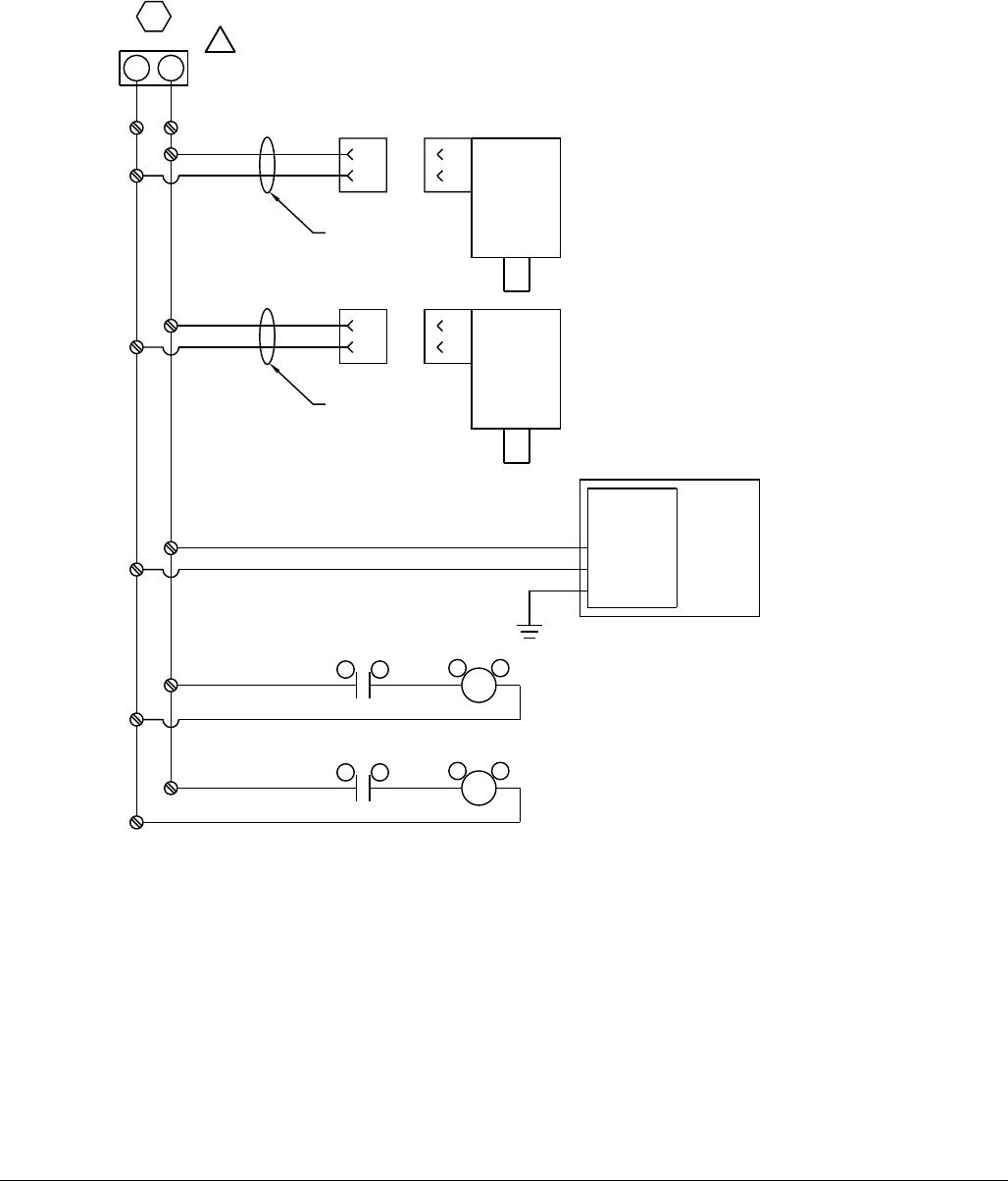
Logic Drawings
313998S 91
FIG. 41: Miscellaneous Power Logic Drawing, Page 2 of 2
861
871
869
867
863
831
859
857
855
853
851
849
847
845
843
841
839
835
837
833
829
827
825
823
821
862
870
865
868
864
832
860
858
856
854
852
850
848
846
844
842
840
836
838
834
830
828
826
824
822
880
887
885
882
878
876
874
872
881
888
884
886
883
879
877
875
873
889
866
CON863
A1 A2
CR642
11 14
MISC A - RED
LOW VOLUME
PG184
185
1860
1840
2
1
2
1
MOTOR
FAN
HYD
HEAT
EXCH'R
1840
1860
2
1
2
1
MOTOR
FAN
MCM
HARNESS
24C518
1840
1860
SOL372
SOL378
HARNESS
24C518
1840
1860
HYD
VALVE
ASSY
1840
1860
CON869
A1 A2
CR711
11 14
1840
1860
M831
M841
8630
8690
LOCATED IN THE MAIN
SUPPORT ENCLOSURE
FOR VARIABLE RATIO ONLY
TERMINAL STRIP MOUNTED
ON BACKPANEL
USED ONLY WITH PRIMARY HEAT
OPTION
USED ONLY WITH HOSE HEAT
OPTION
230VAC POWER TO THE
HYDRAULIC POWER VALVE
230VAC POWER TO THE FAN
MOTOR
230VAC POWER TO THE FAN
MOTOR
2
BL
BR
Technical Data
92 313998S
Technical Data
All other brand names or marks are used for identification purposes and are trademarks of their respective owners.
Maximum Fluid Working Pressure . . . 3000 psi (20.7 MPa, 207 bar)
Maximum Fluid Temperature .......190°F (88°C)
Fluid Inlet Feed Pressure Range ....50psi(0.35 MPa, 3.5 bar) to 250 psi (1.75 MPa, 17.5 bar)
Fluid Inlets ..................... Component A (Red): 1/2 npt(f)
Component B (Blue): 3/4 npt(f)
Fluid Outlets....................Component A (Red): #8 (1/2 in.) JIC (3/4-16 unf), with #5 (5/16 in.) JIC adapter
Component B (Blue): #10 (5/8 in.) JIC (7/8-14 unf), with #6 (3/8 in.) JIC adapter
Fluid Circulation Ports ............ 1/4npsm(m), with plastic tubing, 250 psi (1.75 MPa, 17.5 bar) maximum
Line Voltage Requirement .........230V / 1 phase and 230V / 3 phase Models: 195-264V, 50/60 Hz
400V / 3 phase: 360-440V, 50/60 Hz; see 400 V Power Requirements, page 4
Amperage Requirement...........SeeModels on page 4
Sound Power ...................93dB
Heater Power
(A (Red) and B (Blue) heaters total,
no hose, Heated HFR Models only). . 12 kW
Hydraulic reservoir capacity........8gal. (30 liters)
Recommended hydraulic fluid ......Citgo A/W Hydraulic Oil, ISO Grade 46
Weight ........................Units with 12 kW Heaters: 868 lb (394 kg)
Units without heaters: 634 lb (288 kg)
Wetted Parts ................... Aluminum, stainless steel, zinc-plated carbon steel, brass, carbide, chrome,
fluoroelastomer, PTFE, ultra-high molecular weight polyethylene, chemically
resistant o-rings
Motor Control Module Technical Data
313998S 93
Motor Control Module Technical Data
Overtemperature protection is provided to protect from motor overload.
Current limit, set via the software, is provided as a secondary protection from motor overload.
All installations and wiring must comply with NEC and local electrical codes.
Input Specifications
Input Line Voltage ........................... 0-264 Vac, line-to-line
Input Line Phasing ........................... Single or Three Phase
Input Line Frequency ......................... 50/60 Hz
Input Current per Phase....................... 25A(three-phase), 50A (single-phase)
Maximum Branch Circuit Protection Rating: ....... 30A(three-phase), 63A (single-phase)
Short Circuit Current Rating.................... 5kA
Output Specifications
Output Line Voltage .......................... 0-264 Vac
Output Line Phasing ......................... Three Phase
Output Current .............................. 0-30A
Output Overload............................. 200% for 0.2 seconds
DC Power Supply ............................... 24Vdc,Class 2, Graco-provided power supply
Enclosure ..................................... Type1
Max Ambient Temperature ........................ 50°C (122°F)

All written and visual data contained in this document reflects the latest product information available at the time of publication.
Graco reserves the right to make changes at any time without notice.
For patent information, see www.graco.com/patents.
Original instructions. This manual contains English. MM 313998
Graco Headquarters: Minneapolis
International Offices: Belgium, China, Japan, Korea
GRACO INC. AND SUBSIDIARIES • P.O. BOX 1441 • MINNEAPOLIS MN 55440-1441 • USA
Copyright 2010, Graco Inc. All Graco manufacturing locations are registered to ISO 9001.
www.graco.com
Revised November 2014
Graco Standard Warranty
Graco warrants all equipment referenced in this document which is manufactured by Graco and bearing its name to be free from defects in
material and workmanship on the date of sale to the original purchaser for use. With the exception of any special, extended, or limited warranty
published by Graco, Graco will, for a period of twelve months from the date of sale, repair or replace any part of the equipment determined by
Graco to be defective. This warranty applies only when the equipment is installed, operated and maintained in accordance with Graco’s written
recommendations.
This warranty does not cover, and Graco shall not be liable for general wear and tear, or any malfunction, damage or wear caused by faulty
installation, misapplication, abrasion, corrosion, inadequate or improper maintenance, negligence, accident, tampering, or substitution of
non-Graco component parts. Nor shall Graco be liable for malfunction, damage or wear caused by the incompatibility of Graco equipment with
structures, accessories, equipment or materials not supplied by Graco, or the improper design, manufacture, installation, operation or
maintenance of structures, accessories, equipment or materials not supplied by Graco.
This warranty is conditioned upon the prepaid return of the equipment claimed to be defective to an authorized Graco distributor for verification of
the claimed defect. If the claimed defect is verified, Graco will repair or replace free of charge any defective parts. The equipment will be returned
to the original purchaser transportation prepaid. If inspection of the equipment does not disclose any defect in material or workmanship, repairs will
be made at a reasonable charge, which charges may include the costs of parts, labor, and transportation.
THIS WARRANTY IS EXCLUSIVE, AND IS IN LIEU OF ANY OTHER WARRANTIES, EXPRESS OR IMPLIED, INCLUDING BUT NOT LIMITED
TO WARRANTY OF MERCHANTABILITY OR WARRANTY OF FITNESS FOR A PARTICULAR PURPOSE.
Graco’s sole obligation and buyer’s sole remedy for any breach of warranty shall be as set forth above. The buyer agrees that no other remedy
(including, but not limited to, incidental or consequential damages for lost profits, lost sales, injury to person or property, or any other incidental or
consequential loss) shall be available. Any action for breach of warranty must be brought within two (2) years of the date of sale.
GRACO MAKES NO WARRANTY, AND DISCLAIMS ALL IMPLIED WARRANTIES OF MERCHANTABILITY AND FITNESS FOR A
PARTICULAR PURPOSE, IN CONNECTION WITH ACCESSORIES, EQUIPMENT, MATERIALS OR COMPONENTS SOLD BUT NOT
MANUFACTURED BY GRACO. These items sold, but not manufactured by Graco (such as electric motors, switches, hose, etc.), are subject to
the warranty, if any, of their manufacturer. Graco will provide purchaser with reasonable assistance in making any claim for breach of these
warranties.
In no event will Graco be liable for indirect, incidental, special or consequential damages resulting from Graco supplying equipment hereunder, or
the furnishing, performance, or use of any products or other goods sold hereto, whether due to a breach of contract, breach of warranty, the
negligence of Graco, or otherwise.
FOR GRACO CANADA CUSTOMERS
The Parties acknowledge that they have required that the present document, as well as all documents, notices and legal proceedings entered into,
given or instituted pursuant hereto or relating directly or indirectly hereto, be drawn up in English. Les parties reconnaissent avoir convenu que la
rédaction du présente document sera en Anglais, ainsi que tous documents, avis et procédures judiciaires exécutés, donnés ou intentés, à la suite
de ou en rapport, directement ou indirectement, avec les procédures concernées.
Graco Information
For the latest information about Graco products, visit www.graco.com.
TO PLACE AN ORDER, contact your Graco distributor or call to identify the nearest distributor.
Phone: 612-623-6921 or Toll Free: 1-800-328-0211 Fax: 612-378-3505
