Graco 332291B G3 Standard Automatic Lubrication Pump Users Manual 332291B, Pump, English
2015-04-02
: Graco Graco-332291B-G3-Standard-Automatic-Lubrication-Pump-Users-Manual-685769 graco-332291b-g3-standard-automatic-lubrication-pump-users-manual-685769 graco pdf
Open the PDF directly: View PDF ![]() .
.
Page Count: 34
332291B
EN
Instructions
G3 Standard Automatic
Lubrication Pump
For dispensing of NLGI Grades #000 to #2 greases and oil with at least 40cSt. For
Professional Use Only.
Not approved for use in explosive atmospheres or hazardous locations.
Part Nos., page 3
5100 psi (35.1 MPa, 351.6 bar) Maximum Working Pressure
Important Safety Instructions
Read all warnings and instructions in this
manual. Save these instructions.
TI14705
Conforms to ANSI/UL 73
Certified to CAN/CSA
Std. 22.2 No 68-09
3132066
2332291B
Contents
Part / Model Numbers . . . . . . . . . . . . . . . . . . . . . . . 3
2 Liter Models . . . . . . . . . . . . . . . . . . . . . . . . . . . 3
4 Liter Models . . . . . . . . . . . . . . . . . . . . . . . . . . . 3
8 Liter Models . . . . . . . . . . . . . . . . . . . . . . . . . . . 3
12 Liter Models . . . . . . . . . . . . . . . . . . . . . . . . . . 3
16 Liter Models . . . . . . . . . . . . . . . . . . . . . . . . . . 3
Understanding the Model Number . . . . . . . . . . . 4
Warnings . . . . . . . . . . . . . . . . . . . . . . . . . . . . . . . . . 5
Installation . . . . . . . . . . . . . . . . . . . . . . . . . . . . . . . . 7
Typical Installation . . . . . . . . . . . . . . . . . . . . . . . 8
Choosing an Installation Location . . . . . . . . . . . . 9
System Configuration and Wiring . . . . . . . . . . . 10
Setup . . . . . . . . . . . . . . . . . . . . . . . . . . . . . . . . . . . . 18
Connecting to Auxiliary Fittings . . . . . . . . . . . . . 18
Setting Pump Outlet Volume . . . . . . . . . . . . . . . 19
Loading Grease . . . . . . . . . . . . . . . . . . . . . . . . 19
Filling Oil Unit . . . . . . . . . . . . . . . . . . . . . . . . . . 21
Priming . . . . . . . . . . . . . . . . . . . . . . . . . . . . . . . 21
No Controller Operation . . . . . . . . . . . . . . . . . . . . 22
Troubleshooting . . . . . . . . . . . . . . . . . . . . . . . . . . 24
Maintenance . . . . . . . . . . . . . . . . . . . . . . . . . . . . . . 25
Parts - 2 Liter Models . . . . . . . . . . . . . . . . . . . . . . 26
Parts - 4 Liter and Larger Models . . . . . . . . . . . . . 27
Parts . . . . . . . . . . . . . . . . . . . . . . . . . . . . . . . . . . . . 28
Technical Data . . . . . . . . . . . . . . . . . . . . . . . . . . . . 32
Dimensions . . . . . . . . . . . . . . . . . . . . . . . . . . . . 32
Mounting Pattern . . . . . . . . . . . . . . . . . . . . . . . . 33
Graco Standard Warranty . . . . . . . . . . . . . . . . . . . 34
Graco Information . . . . . . . . . . . . . . . . . . . . . . . 34
Part / Model Numbers
332291B 3
Part / Model Numbers
The Part Number is a six-digit unique number that is only used to order the G3 Pump. Directly related to this six digit
Part Number is the configured Graco Model Number. This configured number identifies the distinct features of a spe-
cific G3 Pump. To help you understand each component that makes up the Model Number see Understanding Your
Model Number, page 4. The tables below shows the relationship between each Part Number and its related Model
Number.
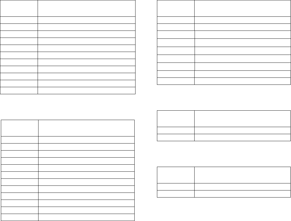
2 Liter Models
4 Liter Models
8 Liter Models
12 Liter Models
16 Liter Models
Part
Numbers Model Number
96G000 G3-G-12NC-2L0000-00C00000
96G001 G3-G-24NC-2L0000-00C00000
96G002 G3-G-ACNC-2L0000-0D000000
96G003 G3-G-12NC-2L0A00-L0C00000
96G005 G3-G-24NC-2L0A00-L0C00000
96G006 G3-G-24NC-2FA00-L0C00000
96G007 G3-G-ACNC-2L0A00-LD000000
96G008 G3-G-ACNC-2LFA00-LD00000
96G050 G3-A-24NC-2L0A00-L0C00000
96G059 G3-A-ACNC-2L0A00-LD000000
96G182 G3-G-24NC-2L0A00-0D00L000
Part
Numbers Model Number
96G038 G3-G-12NC-4L0L00-00C00000
96G040 G3-G-24NC-4L0000-00C00000
96G042 G3-G-ACNC-4L0000-0D000000
96G044 G3-G-12NC-4L0A00-L0C00000
96G048 G3-G-24NC-4L0A00-L0C00000
96G051 G3-A-24NC-4L0A00-L0C00000
96G053 G3-G-24NC-4LFA00-L0C00000
96G055 G3-G-ACNC-4L0A00-LD000000
96G060 G3-A-ACNC-4L0A00-LD000000
96G062 G3-G-ACNC-4LFA00-LD000000
96G179 G3-G-ACNC-4LFA00-0D00L000
96G184 G3-G-24NC-4L0A00-0D00L000
Part
Numbers Model Number
96G039 G3-G-12NC-8L0000-00C00000
96G041 G3-G-24NC-8L0000-00C00000
96G043 G3-G-ACNC-8L0000-0D000000
96G045 G3-G-12NC-8L0A00-L0C00000
96G049 G3-G-24NC-8L0A00-L0C00000
96G052 G3-A-24NC-8L0A00-L0C00000
96G056 G3-G-ACNC-8L0A00-LD000000
96G061 G3-A-ACNC-8L0A00-LD000000
96G187 G3-G-ACNC-8LFA00-0D00L000
Part
Numbers Model Number
96G057 G3-G-ACNC-120A00-LD000000
96G171 G3-G-24NC-120000-00C00000
Part
Numbers Model Number
96G058 G3-G-ACNC-160A00-LD000000
96G172 G3-G-24NC-160000-00C00000
Part / Model Numbers
4332291B
Understanding the Model Number
Use the Code Sample provided below to identify each component’s location in the Model Number. The options for
each component that make up the code are provided on the lists below.
NOTE: Other pump configurations are available that are not documented in this manual. Contact Graco Customer
Service or your local Graco distributor for assistance.
G3 - G = Identifies pump as being a G3; G = Grease
G3 - A = Identifies pump as being a G3; A = Oil
Code aa: Power Source
• 12 = 12 Volts DC
• 24 = 24 Volts DC
• AC = 100 - 240 Volts AC
Code bb: Operation Control
• NC = No Controller
Code cc: Reservoir Capacity (Liters)
• 2L = 2 Liters
• 4L = 4 Liters
• 8L = 8 Liters
• 12 = 12 Liters
• 16 = 16 Liters
Code d: Follower Plate Installed
• F = Follower Plate Installed
• 0 = No Follower Plate
Code e: Low Level Option
• A = External Low Level
• 0 = No Low Level monitoring
Code ff: Options
• 00 = No Options
Code g, h, i, j, k, m, n, p
NOTE: Codes g - p relate to a specific location on the
G3 pump. See FIG. 1 for these locations.
•C = CPC
•D = DIN
• L = Low Level
• 0 = Not populated
G3 -G - NC 00 0 00 0
Code Sample: a a b b - c c d e f f - g h i j k m n p
FIG. 1
k
m
np
h
j
i
g
Warnings
332291B 5
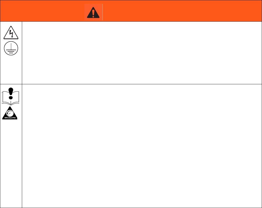
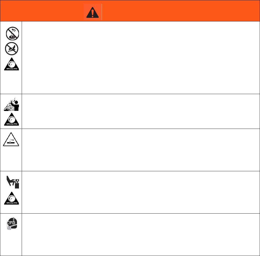
Warnings
The following warnings are for the setup, use, grounding, maintenance, and repair of this equipment. The exclama-
tion point symbol alerts you to a general warning and the hazard symbols refer to procedure-specific risks. When
these symbols appear in the body of this manual or on warning labels, refer back to these Warnings. Product-specific
hazard symbols and warnings not covered in this section may appear throughout the body of this manual where
applicable.
WARNING
ELECTRIC SHOCK HAZARD
This equipment must be grounded. Improper grounding, setup, or usage of the system can cause
electric shock.
• Turn off and disconnect power at main switch before disconnecting any cables and before servicing
or installing equipment.
• Connect only to grounded power source.
• All electrical wiring must be done by a qualified electrician and comply with all local codes and
regulations.
EQUIPMENT MISUSE HAZARD
Misuse can cause death or serious injury.
• Do not operate the unit when fatigued or under the influence of drugs or alcohol.
• Do not exceed the maximum working pressure or temperature rating of the lowest rated system
component. See Technical Data in all equipment manuals.
• Use fluids and solvents that are compatible with equipment wetted parts. See Technical Data in all
equipment manuals. Read fluid and solvent manufacturer’s warnings. For complete information
about your material, request MSDS from distributor or retailer.
• Turn off all equipment and follow the Pressure Relief Procedure when equipment is not in use.
• Check equipment daily. Repair or replace worn or damaged parts immediately with genuine manu-
facturer’s replacement parts only.
• Do not alter or modify equipment. Alterations or modifications may void agency approvals and create
safety hazards.
• Make sure all equipment is rated and approved for the environment in which you are using it.
• Use equipment only for its intended purpose. Call your distributor for information.
• Route hoses and cables away from traffic areas, sharp edges, moving parts, and hot surfaces.
• Do not kink or over bend hoses or use hoses to pull equipment.
• Keep children and animals away from work area.
• Comply with all applicable safety regulations.
Warnings
6332291B
+
SKIN INJECTION HAZARD
High-pressure fluid from dispensing device, hose leaks, or ruptured components will pierce skin. This
may look like just a cut, but it is a serious injury that can result in amputation. Get immediate surgical
treatment.
• Do not point dispensing device at anyone or at any part of the body.
• Do not put your hand over the fluid outlet.
• Do not stop or deflect leaks with your hand, body, glove, or rag.
• Follow the Pressure Relief Procedure when you stop dispensing and before cleaning, checking, or
servicing equipment.
• Tighten all fluid connections before operating the equipment.
• Check hoses and couplings daily. Replace worn or damaged parts immediately.
PRESSURIZED EQUIPMENT HAZARD
Over-pressurization can result in equipment rupture and serious injury.
• A pressure relief valve is required at each pump outlet.
• Follow Pressure Relief Procedure in this manual before servicing.
PLASTIC PARTS CLEANING SOLVENT HAZARD
Many solvents can degrade plastic parts and cause them to fail, which could cause serious injury or
property damage.
• Use only compatible water-based solvents to clean plastic structural or pressure-containing parts.
•See Technical Data in this and all other equipment instruction manuals. Read fluid and solvent
manufacturer’s MSDSs and recommendations.
MOVING PARTS HAZARD
Moving parts can pinch, cut or amputate fingers and other body parts.
• Keep clear of moving parts.
• Do not operate equipment with protective guards or covers removed.
• Pressurized equipment can start without warning. Before checking, moving, or servicing equipment,
follow the Pressure Relief Procedure and disconnect all power sources.
PERSONAL PROTECTIVE EQUIPMENT
Wear appropriate protective equipment when in the work area to help prevent serious injury, including
eye injury, hearing loss, inhalation of toxic fumes, and burns. This protective equipment includes but is
not limited to:
• Protective eyewear, and hearing protection.
• Respirators, protective clothing, and gloves as recommended by the fluid and solvent manufacturer
WARNING
Installation
332291B 7
Installation
Grounding
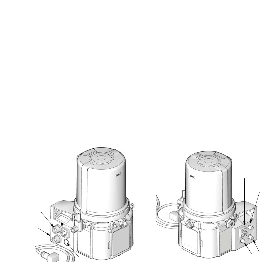
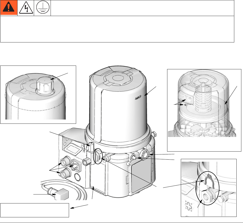
Component Identification
Key:
AReservoir
B Adjustable Pump Element (1 included. Can accommodate 3
total)
C Pressure Relief Valve (Not included / required for each outlet
- Available from Graco. See Parts, page 30.)
D Zerk Inlet Fill Fitting (1 included / grease models only)
E Pump Outlet Plug (2 included)
F Volume Control Spacers (2 included. More spacers = less
output volume per stroke) (also see FIG. 13, page 19)
G Fuse (DC models only - Not included, not shown. Available
from Graco. See Parts, page 30.)
H Power / Sensor Panel (both sides; only one side shown)
I Part Number / Model Number example only shown, (see
page 4, Understanding the Model Number, for details)
J Power Cord (DIN shown)
K Follower Plate (grease models only / not available on all
grease models)
L Vent Hole for Follower Plate (grease models only / not
available on all grease models)
M Fill cap (oil models only)
The equipment must be grounded. Grounding reduces the risk of electric shock by providing an escape wire
for the electrical current in the event of malfunction or breakdown. This product is equipped with a cord having
an equipment grounding conductor. The wire with insulation having an outer surface that is green with or
without yellow stripes is the grounding wire.
FIG. 2:
A
D
H
B
E
C
J
F
I
G3-G-24NC-2L0A00-L0C00000
Grease Models with Follower
Plate
K
L
96GXXX
Oil Models
M
Grease Models
Installation
8332291B
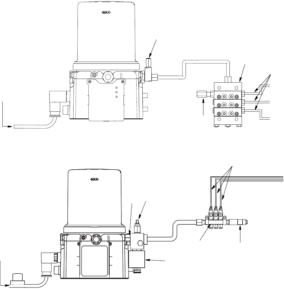
Typical Installation
Divider Installations
Injector Installations
A Connected to fuse / power
B Pressure relief valve (Not included/ required for each outlet -
user supplied. See Parts, page 30)
D Series progressive divider valves (Divider Installations)
- Injectors (Injector Installations)
E To lube points
F - Proximity Switch (Divider Installations)
- Pressure switch (Injector Installations)
G Vent valve (Not included / available from Graco. See Parts,
page 31.)
H Return to reservoir
A
B
D
E
F
A
B
D
E
F
H
G

Installation
332291B 9
Choosing an Installation Location
• Select a location that will adequately support
the weight of the G3 Pump and lubricant, as
well as all plumbing and electrical connections.
• Refer to the two mounting hole layouts provided
in the Mounting Pattern section of this manual,
page 33.
NOTE: The two mounting hole layouts provided
in the Technical Data section show the only cor-
rect installation patterns to use for mounting the
G3. No other installation configurations should
be used.
• Use designated mounting holes and provided
configurations only.
• Always mount the G3 oil models upright.
• If the G3 grease model is going to be operated
in a tilted or inverted position for any period of
time, you must use a model that includes a fol-
lower plate, otherwise the G3 must be mounted
upright. Refer to your model number to confirm
if a follower plate was installed on your pump.
See page 4, Understanding the Model Number
to identify this character in your model number.
• Use the three fasteners (included) to secure the
G3 to the mounting surface.
• Some installations may require an additional
reservoir support bracket. Consult your Graco
distributor for assistance with this installation.
AUTOMATIC SYSTEM ACTIVATION HAZARD
If the system is equipped with has an automatic timer (user supplied) that activates the pump lubrication system
when power is connected or when exiting the programming function, unexpected activation of the system could result
in serious injury, including skin injection and amputation.
Before you install or remove the lubrication pump from the system, disconnect and isolate all power supplies and
relieve all pressure.
Installation
10 332291B
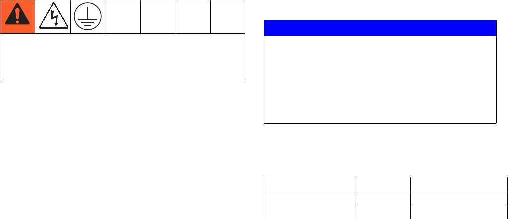
System Configuration and Wiring
If the product is permanently connected:
• it must be installed by a qualified electrician or ser-
viceman.
• it must be connected to a grounded, permanent wir-
ing system.
If an attachment plug is required in the end use
application:
• it must be rated for the product electrical specifica-
tions.
• it must be an approved, 3-wire grounding type
attachment plug.
• it must be plugged into an outlet that is properly
installed and grounded in accordance with all local
codes and ordinances.
• when repair or replacement of the power cord or
plug is required, do not connect the grounding wire
to either flat blade terminal.
Fuses
Fuse Kits are available from Graco. The following Table
identifies the correct fuse to use for your input voltage
and the corresponding Graco Kit number.
Recommendations for Using Pump in
Harsh Environments
• Use pump with CPC style power cable.
• If using a DIN style power or alarm harness with a
right angle mating connector, make sure the con-
nector does not exit the unit in the UP direction.
• Use a corrosion preventative electrical grease on all
contacts.
.
Improper installation of the grounding conductor may
result in a risk of electric shock. This product must be
installed by a qualified electrician in compliance with
all state and local codes and regulations.
NOTICE
Fuses (user supplied) are required on all DC mod-
els. To avoid equipment damage:
• Never operate G3 Pump DC models without a
fuse installed.
• A fuse of the correct voltage must be installed in
line with the power entry to the system.
Input Voltage Fuse Value Graco Kit No.
12 VDC 7.5 A 571039
24 VDC 4 A 571040
Installation
332291B 11
Wiring and Installation Diagrams
The following Table identifies the wiring and installation diagrams for the cable included with the pump provided in
this manual.
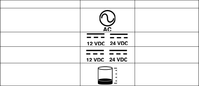
Diagram Symbol Page #
Power DIN AC 12
Power DIN DC 13
Power CPC DC 14
Low Level Outputs 15
Installation
12 332291B
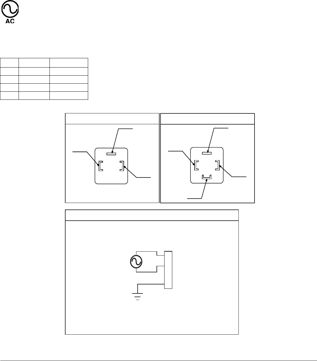
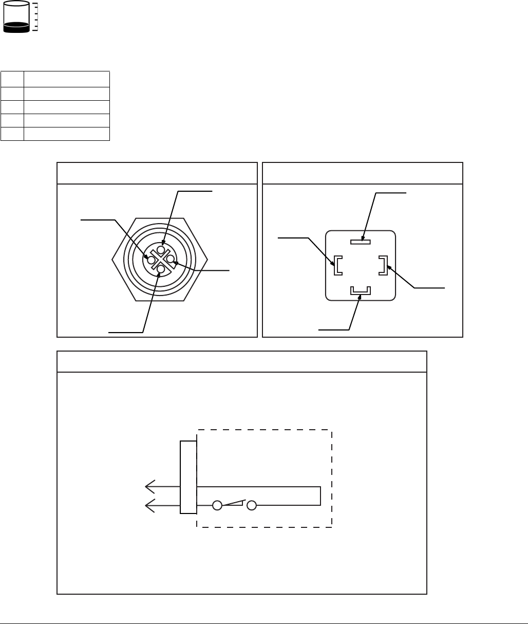
Power DIN AC - 15 foot: Part No. 16U790
Pin and Related Wire Color (FIG. 3)
Pin Pin Name Color
1 Line Black
2 NEUTRAL White
3 Not Used Not Used
4GROUND Green
FIG. 3
(4)
(2)
(1)
1
2
3
4
Example Wiring Diagram
Connector on Housing Connector on Cable
(4)
(1)
(3)
(2)
Installation
332291B 13
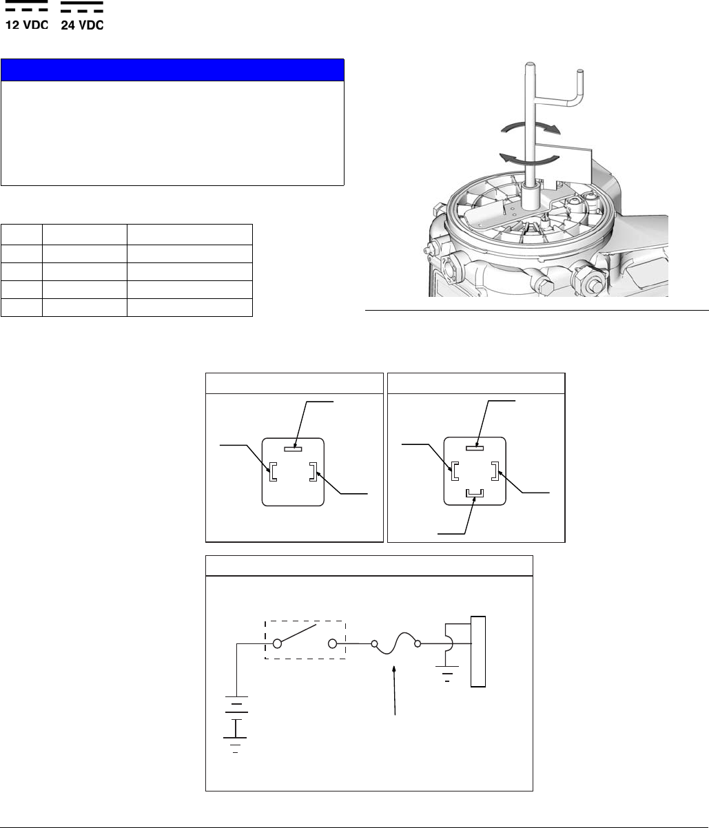
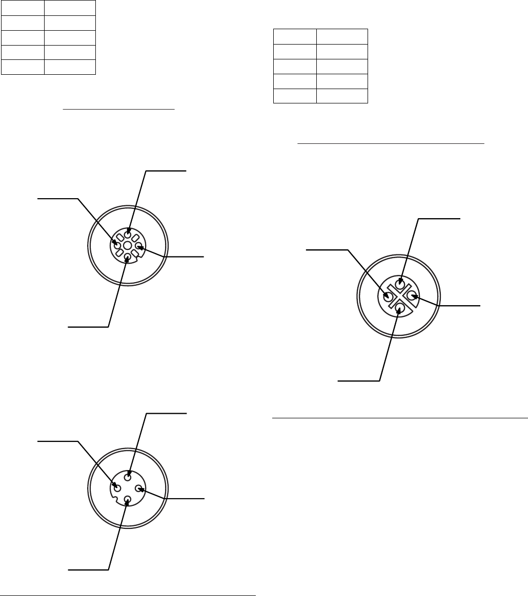
Power DIN DC - 15 foot: Part No. 16U790
Pin and Related Wire Color (FIG. 5)
NOTICE
Be sure when power is applied that stirring paddle
rotates clockwise (when viewed from the top). If it is
wired incorrectly paddle could rotate counter-clockwise
which will damage the pump’s internal components. If
this happens, stop the pump immediately and wire unit
correctly.
Pin Pin Name Color
1-VDC Black
2+VDC White
3 Not Used Not Used
4 Not Used Green FIG. 4
FIG. 5
Ignition Switch
Fuse
1
2
3
4
Example Wiring Diagram
Connector on Housing
12V-pump - 7.5A - Graco kit #571039
24V pump - 4A - Graco kit #571040
(4)
(2)
(1)
Connector on Cable
(4)
(1)
(3)
(2)
Installation
14 332291B
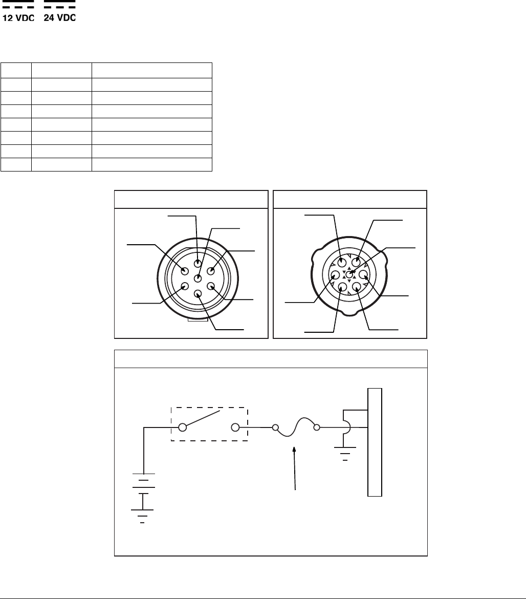
Power CPC DC - 15 foot: Part No. 126217
Pin and Related Wire Color (FIG. 6)
Pin Pin Name Color
1 Not Used Not Used
2-VDC Black
3+VDC White
4 Not Used Not Used
5 Not Used Not Used
6 Not Used Not Used
7 Not Used Green
FIG. 6
(1)
(2)
(3)
(4)
(5)
(6)
(7)
Example Wiring Diagram
Connector on Housing Connector on Cable
Ignition Switch
Fuse
1
2
3
4
5
6
7
12V-pump - 7.5A - Graco kit #571039
24V pump - 4A - Graco kit #571040
(1)
(3)
(2)
(7)
(6) (5)
(4)
Installation
16 332291B
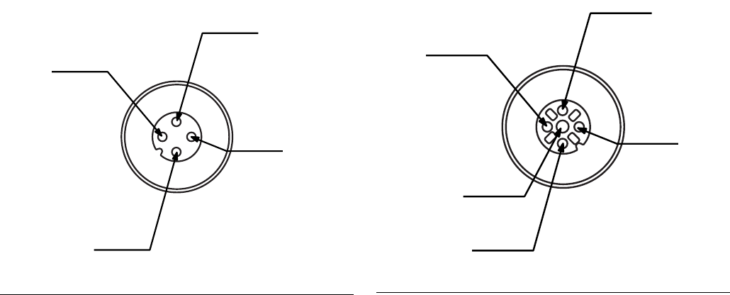
Part No. 124333: Cable Pin Out (M12)
Wire Colors
Part No. 124300: Field Wireable Pin Out
(M12)
Wire Colors
Item No. Color
1Brown
2White
3Blue
4Black
FIG. 8
Item No. Color
1Brown
2White
3Blue
4Black
FIG. 9
Installation
332291B 17
Part No. 124594: 4 Pin Eurofast Field
Wireable Connector
Part No. 124595: 5 Pin Eurofast Field
Wireable Connector
FIG. 10
FIG. 11
Setup
18 332291B
Setup
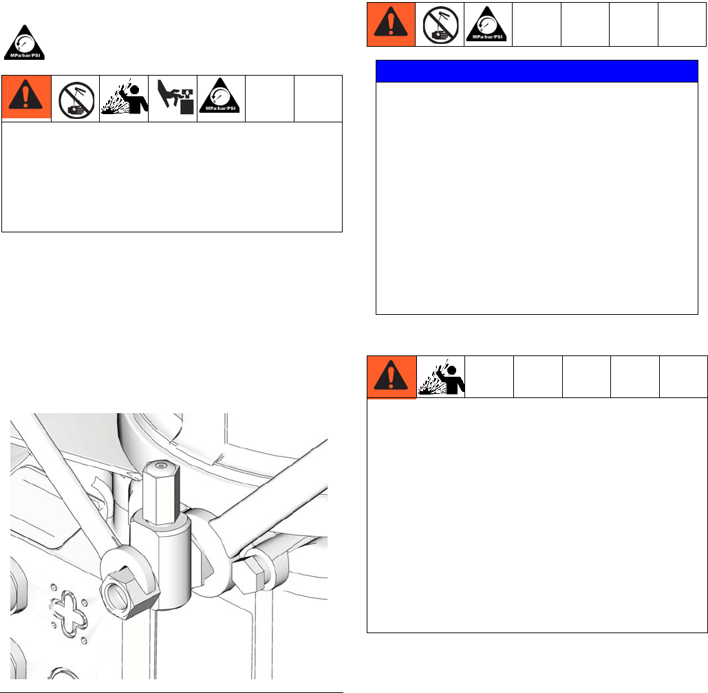
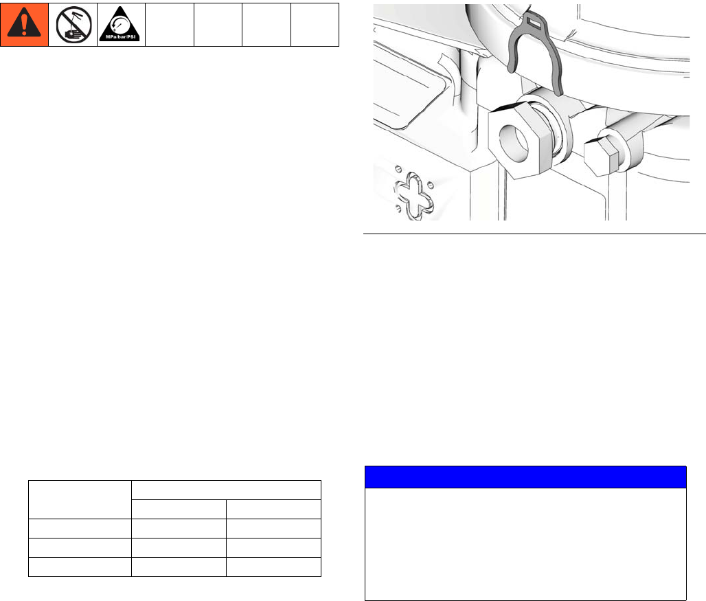
Pressure Relief
Follow the Pressure Relief Procedure whenever
you see this symbol.
Relieve pressure in system using two wrenches work-
ing in opposite directions on pump element and pump
element fitting to slowly loosen fitting only until fitting
is loose and no more lubricant or air is leaking from fit-
ting.
NOTE: When loosening pump element fitting, do NOT
loosen pump element. Loosening pump element will
change the output volume.
Connecting to Auxiliary Fittings
Pressure Relief Valves
NOTE: A pressure relief valve can be purchased from
Graco. See Parts, page 30.
This equipment stays pressurized until pressure is
manually relieved. To help prevent serious injury
from pressurized fluid, such as skin injection,
splashing fluid and moving parts, follow the Pressure
Relief Procedure when you stop spraying and before
cleaning, checking, or servicing the equipment.
FIG. 12
NOTICE
Do not attach unsupported equipment to auxiliary fit-
tings such as fill ports and pump element. Attaching
unsupported equipment to these fitting can result in
irreparable housing damage.
• Always use two wrenches working in opposite
directions when connecting anything to pump
element or auxiliary fittings. See FIG. 12 for an
example.
• Torque pump element fittings to 50 in. lbs (5.6
N•m).
• When connecting pump element into housing
torque to 50 in. lbs (5.6 N•m).
To prevent over-pressurization, which can result in
equipment rupture and serious injury, a pressure relief
valve appropriate for the lubrication system must be
installed close to every pump outlet to alleviate unin-
tended pressure rises in the system and protect the G3
pump from damage.
• Only use a pressure relief valve that is rated for no
more than the working pressure of the G3 pump it
is installed on. See Technical Data, page 27.
• Install a pressure relief valve close to every pump
outlet; before any auxiliary fitting.
Setup
332291B 19
Setting Pump Outlet Volume
NOTE:
• Before making any adjustments to pump volume,
Relieve Pressure following procedure on page 18.
• Only use Graco supplied spacers to control output
volume.
• It may be necessary to repeat this outlet volume
setup procedure after the pump is operating to
re-adjust the volume of dispensed fluids.
1. Use a wrench to turn pump element counter-clock-
wise to loosen. Do not remove entire pump element.
Only back pump element out enough to allow
spacer to be slid on or off.
2. If needed, remove or insert spacers to achieve
required pump output volume. A tool may be
needed to facilitate removal.
Pump volume control is set using either no (0) spac-
ers, 1 or 2 spacers (FIG. 13).
Do not use more than 2 spacers to adjust output vol-
ume.
NOTE:
• The amount of dispensed volume can vary depend-
ing on external conditions such as lubricant tem-
perature and back pressure from downstream
connections.
• Use of these volume adjustment in conjunction with
setting the ON time of the pump will allow for control
of the output volume.
• Use these volume adjustments as a starting point
and adjust as necessary to ensure desired lubrica-
tion dispense.
3. Tighten pump element fitting. Torque fitting to 50 in.
lbs (5.6 N•m).
Loading Grease
To ensure optimal performance from the G3:
• Only use NLGI #000 - #2 greases appropriate for
your application, automatic dispensing, and the
equipment’s operating temperature. Consult with
machine and lube manufacturer for details.
• The reservoir can be filled using a hand operated
pump, pneumatic pump or electric transfer pump.
• Do not overfill (FIG. 15).
• Do not operate G3 without reservoir attached.
No. Spacers
Output Volume / Minute
cubic inches cubic cm
20.122
10.183
00.254
FIG. 13
NOTICE
• Always clean fitting (D) with a clean dry cloth
prior to filling reservoir. Dirt and/or debris can
damage pump and/or lubrication system.
• Care must be used when filling the reservoir
using a pneumatic or electric transfer pump to
not pressurize and break the reservoir.
Setup
20 332291B
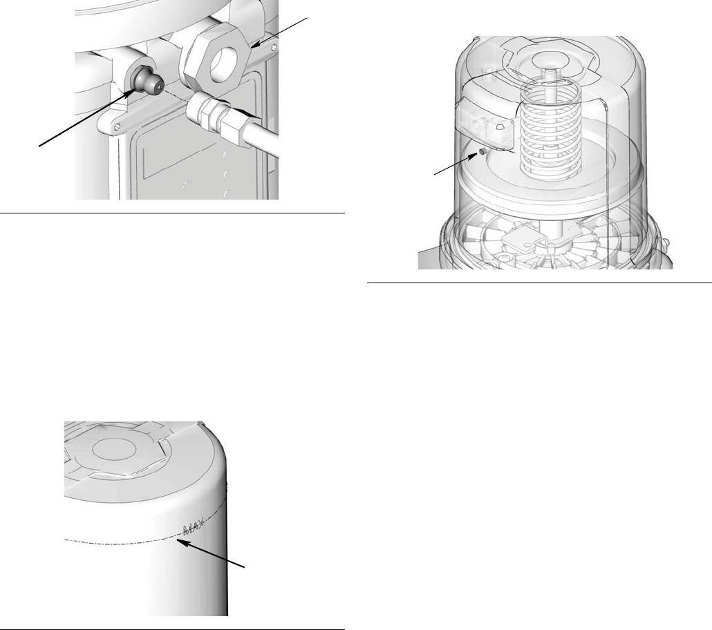
Models without a follower plate:
1. Connect fill hose to inlet fitting (FIG. 14).
2. For higher viscosity fluids, start pump to rotate stir-
ring paddle during fill to prevent air pockets from
forming in grease.
For models using an external controller, start pump
operation per your controller specifications.
3. Fill reservoir with NLGI grease to max fill line.
NOTE: Vent port, located in rear of reservoir, should not
be used as an overfill port/indicator.
4. Remove fill hose.
Models with a follower plate:
1. Connect fill hose to inlet fitting (FIG. 14).
2. For higher viscosity fluids, start pump to rotate stir-
ring paddle during fill to prevent air pockets from
forming in grease.
For models using an external controller, start pump
operation per your controller specifications.
3. Fill reservoir with grease until seal of follower plate
breaches the vent hole (FIG. 16) and the majority of
air is expelled from the reservoir.
NOTE: Vent port, located in rear of reservoir, should not
be used as an overfill port/indicator.
4. Remove fill hose.
Changing Greases
When changing greases, always use compatible fluids
or greases.
FIG. 14
FIG. 15
D
E
max fill line
FIG. 16
vent hole
Setup
332291B 21
Filling Oil Unit
• Only use oil appropriate for your application, auto-
matic dispensing, and the equipment’s operating
temperature. Consult with machine and lube manu-
facturer for details.
• The reservoir can be filled using a hand operated
pump, pneumatic pump or electric transfer pump.
• Do not overfill (FIG. 17).
• Do not operate G3 without reservoir attached.
• Only use oils with viscosity at least 40 cSt.
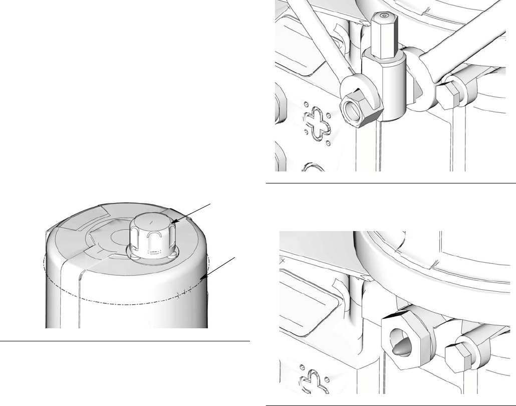
1. Remove fill cap (a).
2. Pour oil into reservoir to fill line (b).
3. Replace fill cap. Hand tighten cap, securely.
Priming
NOTE: It is not necessary to prime pump every time
pump is filled with lubricant.
Pump only requires priming the first time it is used or if it
is allowed to run dry.
1. Loosen pump element fitting (FIG. 18).
NOTE: When loosening pump element fitting, do NOT
loosen pump element. Loosening pump element will
change the output volume
2. Only run pump until air is no longer dispensed with
the lubricant coming out of element fitting (FIG. 19).
3. Tighten pump element fitting using two wrenches
working in opposite directions (FIG. 18).
FIG. 17
a
b
FIG. 18
FIG. 19
No Controller Operation
22 332291B
No Controller Operation
The G3 Pump can be controlled using an external, user
supplied, power source and controller.
Refer to the Typical Installation diagrams provided on
page 8 for correct location of the required pump ground
wire and fuses.
NOTE:
• When using an external power source and control-
ler, Pump ON (Run) Time should be set for no lon-
ger than 30 minutes.
• In most cases, Pump OFF (Rest) Time should be
twice as long as Pump ON (Run) time. If alternative
ON / OFF times are required, contact Graco Cus-
tomer Service for assistance.
Low Level Output Option
Some G3 pumps without controllers include a Low Level
Output Option. It can be configured with an M12 con-
nector in code location “G” or with a DIN connector in
code location “K”. (See Understanding the Model Num-
ber, page 4.)The low level signal is monitored across
PINS 3 and 4. For PIN 3 and 4 locations and wiring
information the Low Level Outputs diagram, page 15.
NOTE: A low level warning is triggered when the con-
troller detects PINS 3 and 4 have momentarily closed.
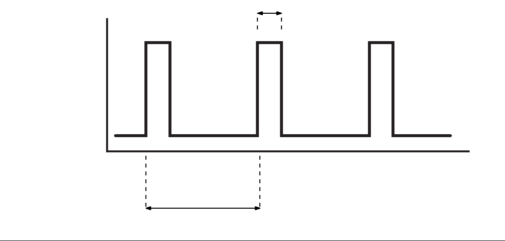
Grease Pumps
When the grease level has reached a low warning level,
PINS 3 and 4 momentarily close (1 time per paddle rev-
olution) sending the signal that the fluid has reached a
low level to the controller.
To ensure that a low level condition has been met, 3 or
more low level triggers must be detected within 1 minute
or less.
See FIG. 20 for an illustration of a typical Low Level Out-
put response to low grease level.
Typical Low Level Output Response with Low Level Fluid in Grease Models
FIG. 20
200 ms
Open
Contact
Position
Closed
3 s

No Controller Operation
332291B 23
Oil Pumps
When the oil level has reached a low warning level,
PINS 3 and 4 close, sending the signal to the controller
that the fluid has reached a low level.
To ensure that a low level condition has been met, the
low level trigger must be detected for 10 continuous sec-
onds.
See FIG. 21 for an illustration of a typical Low Level Out-
put response to low oil level.
Typical Low Level Output Response with Low Level Fluid in Oil Models
FIG. 21
Open
Contact
Position
Closed
Troubleshooting
24 332291B
Troubleshooting
Problem Cause Solution
Unit does not power on Incorrect/loose wiring Refer to Installation instructions,
page 7.
Unit does not power on (DC models
only)
Tripped external fuse due to internal
component failure Contact Graco Customer Service.
Tripped external fuse due to pump-
ing non-cold weather lubricant in
cold weather -13°F (-25°C)
Replace lubricant with pumpable
lubricant, rated for environmental
conditions and application.
Replace fuse.
Unit does not power on (AC models
only)
Tripped internal power supply fuse
due to power supply failure Contact Graco Customer Service.
Lubricant leaks past seal located on
the bottom of the reservoir
Reservoir retaining tabs are
cracked or broken
Replace reservoir.
Reservoir is being pressurized
during filling
Ensure vent hole is not plugged.
If problem persists, contact Graco
Customer Service or your local
Graco distributor for assistance.
Unit not pumping during ON cycle,
but external controller functions
Failed motor Replace unit.
Follower plate is not going down
Air is trapped in the reservoir
between the follower plate and lubri-
cant
Add grease following Loading
Grease instructions, page 19.
Ensure air is purged.
Pump takes several minutes before
it begins pumping at the highest
pump volume setting (no stroke
adjust spacers installed)
Pumping non-cold weather lubricant
in cold weather -13°F (-25°C)
Add 1 stroke adjust spacer and
adjust lube cycle time to accommo-
date the difference in pump volume
per stroke.
In an Injector System without sen-
sor feedback, unit does not vent
properly
Vent valve time needs to be config-
ured
Adjust external vent valve control
time.

Maintenance
332291B 25
Maintenance
Frequency Component Required Maintenance
Daily and at refill Zerk Fittings Keep all fittings clean using a clean
dry cloth. Dirt and/or debris can dam-
age pump and/or lubrication system.
Daily G3 Pump Unit and Reservoir Keep pump unit and reservoir clean
using a clean dry cloth.
Monthly External Wiring Harness Verify external harnesses are
secure.
Parts - 2 Liter Models
26 332291B
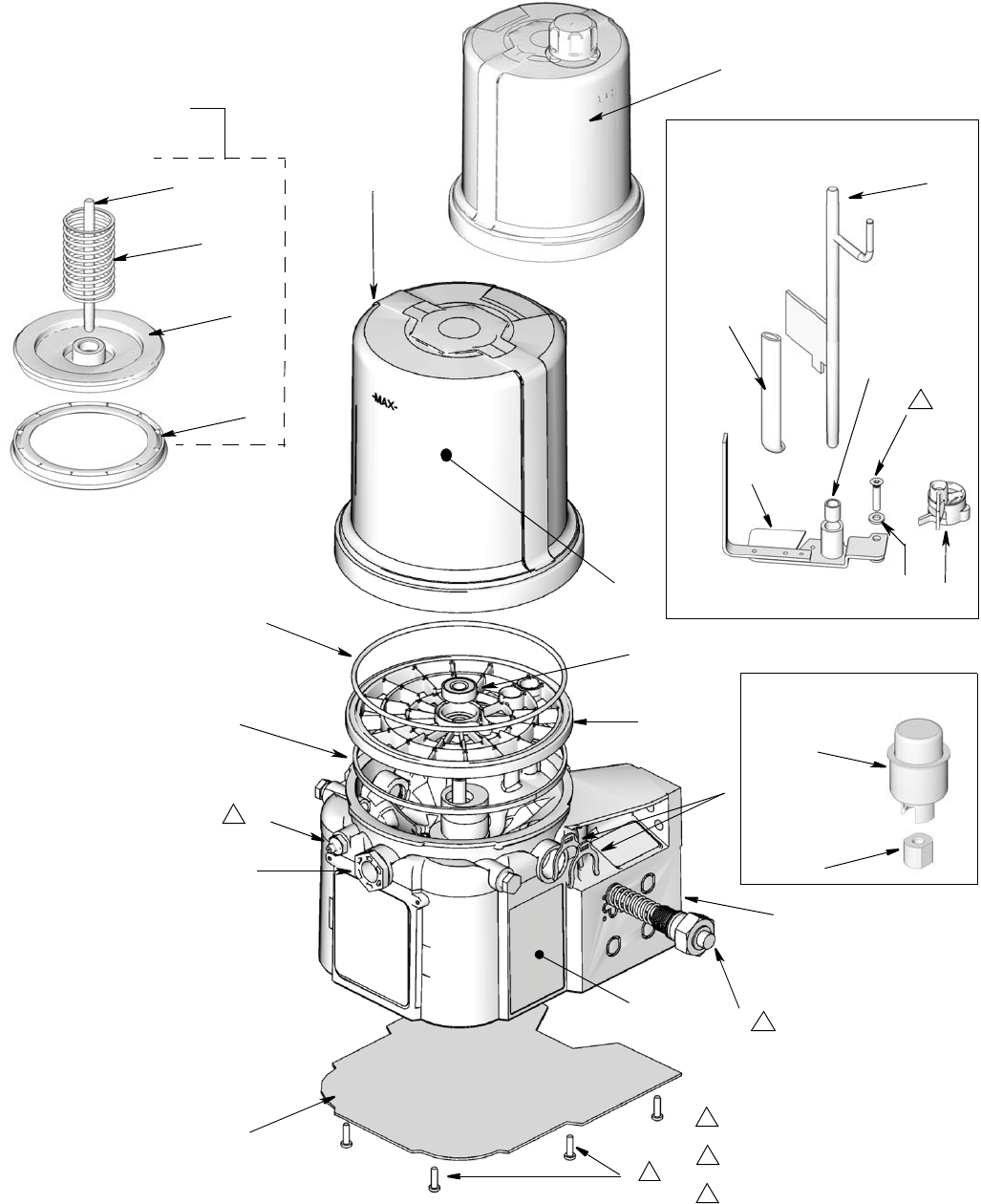
Parts - 2 Liter Models
40a
44
14
1
42
13
18
17
36
33
37
41
21
15
4
3
Follower Plate
Models Only
43
Torque to 4 in. lbs (0.45 N.m)
1
Torque to 30 in. lbs (3.4 N.m)
2
Torque to 50 in. lbs (5.6 N.m)
3
2
3
40b
3
45
35
27
23
16
60
57
Low Level Grease Models Only
Low Level Oil Models Only
66
67
1
12
Parts - 4 Liter and Larger Models
332291B 27
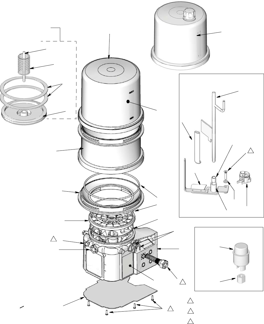
Parts - 4 Liter and Larger Models
40a
44
35
14
1
41
13
18
17
16
36
33
37
42
21
15
4
3
Follower Plate
Models Only
43
Torque to 4 in. lbs (0.45 N.m)
1
Torque to 30 in. lbs (3.4 N.m)
2
Torque to 50 in. lbs (5.6 N.m)
3
2
3
61
62
40b
3
27 1
45
60
23
57
Low Level Grease Models Only
67
66
Low Level Oil Models Only
12
Parts
28 332291B
Parts
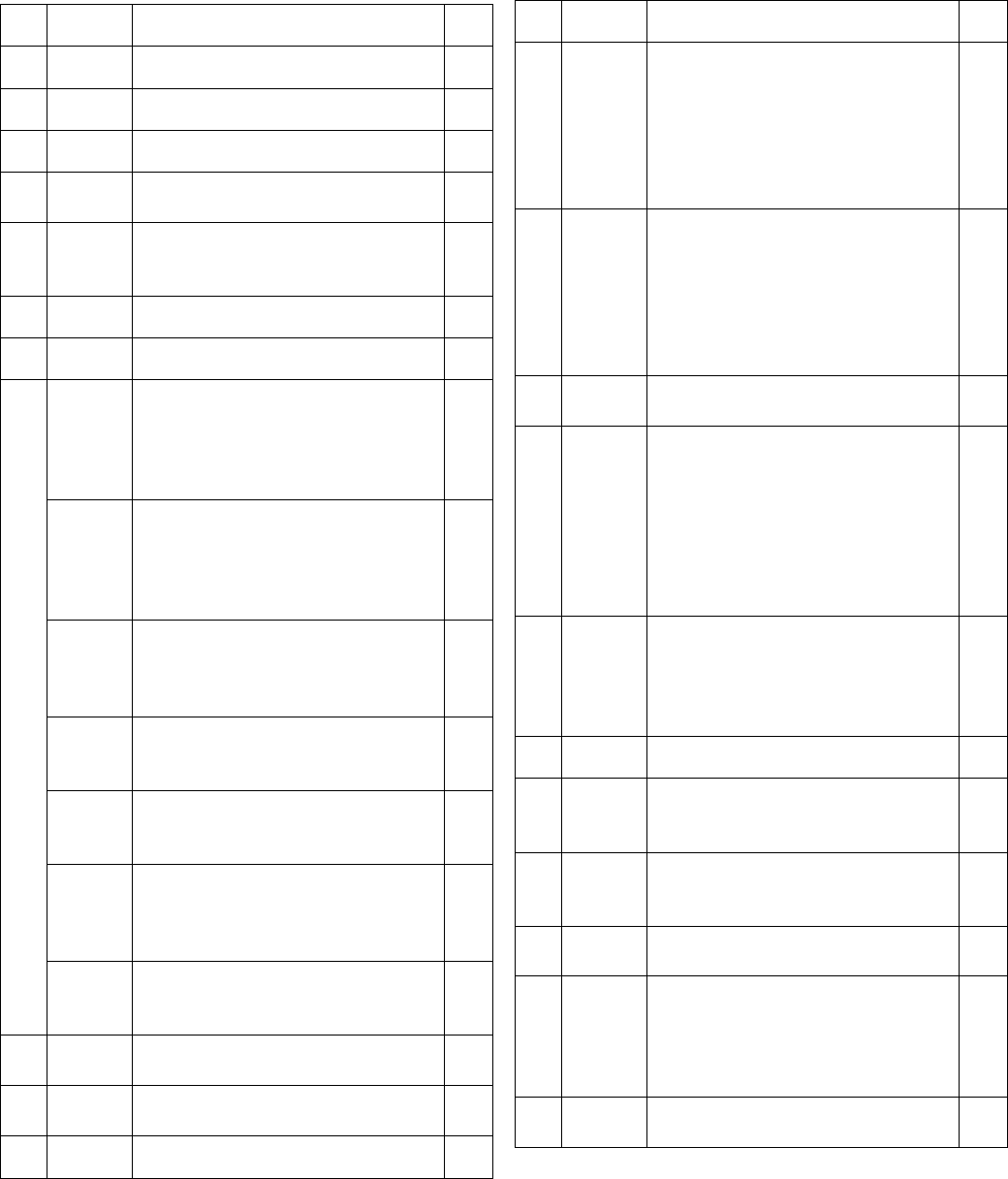
Ref Part Description Qty
1 BASE, three pump housing 1
3 278142 COVER, bottom, with seal 1
4 115477 SCREW, mach, torx pan hd 9
12 127079 RECT-RING, included in kit
571042, 571069, 571179 1
13 124396
O-RING, 258, included in Kit
571042, 571044, 571045, 571069,
571179
2
14 PLATE, ricer 1
15 BEARING, ball 1
16
PADDLE, stirring, 2 Liter models
without follower plate - models
96G000, 96G001, 96G002,
96G003, 96G005, 96G007,
96G182, included in Kit 571044,
1
PADDLE, stirring, 4 Liter models
without follower plate - models
96G038, 96G040, 96G042,
96G044, 96G048, 96G055,
96G184
1
PADDLE, stirring, 8 Liter models
without follower plate - models
96G039, 96G041, 96G043,
96G045, 96G049, 96G056
1
PADDLE, stirring, 12 Liter models
without follower plate - model
96G057, 96G171
1
PADDLE, stirring, 16 Liter models
without follower plate - model
96G058, 96G172
1
PADDLE, stirring, 2 Liter models
with follower plate - models
96G006, 96G008, included in Kit
571045
1
PADDLE, stirring, 4 liter models
with follower plate - models
96G053, 96G062, 96G179
1
17 PUMP, element, included in Kit
571041 1
18 16F368 SPACER, stroke adjust, included
in Kit 571041 2
21 278145 PLUG, pump, 3/4-16 2
23
278136
PADDLE, low level, models
96G003-96G008, 96G038,
96G044, 96G045, 96G048,
96G049, 96G053,
96G055-96G058, 96G062,
96G179, 96G182, 96G184,
96G187
1
27 123025
SCREW, M6, models
96G003-96G008, 96G038,
96G044, 96G045, 96G048,
96G049, 96G053,
96G055-96G058, 96G062,
96G179, 96G182, 96G184,
96G187
1
33
16A579 LABEL, safety 1
35
WIPER, stirring, models without
follower plate - models 96G000,
96G001, 96G002, 96G003,
96G005, 96G007,
96G038-96G045, 96G048,
96G049, 96G055-96G058,
96G171, 96G172, 96G182,
96G184, included in Kit 571044
1
WIPER, stirring, models with fol-
lower plate - models 96G006,
96G008, 96G053, 96G062,
96G179, 96G187, included in Kit
571045
1
36 LABEL, brand 1
37 123741
FITTING, zerk, grease, not
included on models
96G050-96G052, 96G059-96G061
1
40a 24E984
RESERVOIR, 2 liter, grease,
96G000-96G008, 96G182,
included in Kit 571042, 571069
1
40b 16G021 RESERVOIR, 2 liter, oil, 96G050,
96G059, included in Kit 571179 1
40a 24B702
RESERVOIR, 4 liter, grease,
96G038, 96G040, 96G042,
96G044, 96G048, 96G053,
96G055, 96G062, 96G179,
96G184, included in Kit 571183
1
40b 16G020 RESERVOIR, 4 liter, oil, 96G051,
96G060 1
Ref Part Description Qty
Parts
332291B 29
40a
RESERVOIR, 8 liter, grease,
96G039, 96G041, 96G043,
96G045, 96G049, 96G056,
96G187
1
40b RESERVOIR, 8 liter, oil, 96G052,
96G061, included in Kit 571182 1
40a RESERVOIR, 12 liter, 96G057,
96G077, 96G171 1
40a RESERVOIR, 16 liter, 96G058,
96G172 1
41
278139 SEAL, follower plate, 2 liter models
96G006, 96G008 1
16F472 SEAL, follower plate, 4 liter models
96G053, 96G062, 96G179 2
42
PLATE, follower, 2 liter models
96G006, 96G008 1
PLATE, follower, 4 liter models
96G053, 96G062, 96G179 1
43
ROD, follower plate, 2 liter models
96G006, 96G008 1
ROD, follower, 4 liter models
96G053, 96G062, 96G179
44
SPRING, compression, 2 liter
models 96G006, 96G008 1
SPRING, compression, 4 liter
models 96G053, 96G062, 96G179 1
45† 24D838
BAFFLE, low level, 2 liter models
96G003, 96G005, 96G007,
96G182
1
† 24E246
BAFFLE, low level, 4 liter models
96G044, 96G048, 96G055,
96G184
1
†24F836
BAFFLE, low level, 8 liter models
96G045, 96G049, 96G052,
96G056, 96G061
1
†24F923
BAFFLE, low level, 12 liter models
96G057 1
†24F924
BAFFLE, low level, 16 liter models
96G058 1
57 117156
BEARING, sleeve, models
96G003-96G008, 96G038,
96G044-96G045, 96G048,
96G049, 96G053,
96G055-96G058, 96G062,
96G179, 96G182, 96G184,
96G187
1
Ref Part Description Qty
58
196548
LABEL, models 96G002, 96G007,
96G008, 96G042, 96G043,
96G055-96G062, 96G179,
96G187
1
60 16D984
WASHER, low level, models
96G003-96G008,
96G033-96G038,
96G044-96G045, 96G048,
96G049, 96G053,
96G055-96G058, 96G062,
96G179, 96G182, 96G184,
96G187
2
61
RESERVOIR, mid-section, 8 liter
models 96G039, 96G041,
96G043, 96G045, 96G049,
96G052, 96G056, 96G061,
96G187
1
RESERVOIR, mid-section, 12 liter
models 96G057, 96G171 2
RESERVOIR, mid-section, 16 liter
models 96G058, 96G172 3
62
ADAPTER, reservoir, models
96G038-96G045, 96G048,
96G049, 96G051-96G053,
96G055, 96G057, 96G058,
96G060-96G062, 96G171,
96G172, 96G179, 96G184,
96G187
1
66 126417
NUT, oil, models 96G050,
96G051, 96G052, 96G059,
96G060, 96G061
67 24N806
FLOAT, oil, models 96G050,
96G051, 96G052, 96G059,
96G060, 96G061
200
126217
CABLE,15 ft (4.5 m), SOOW
w/7pos, 3 pin, 90 deg (See Wiring
Diagram, page 14)
1
16U790 CABLE, DIN, bare, (See Wiring
Diagram, page 12) 1
Ref Part Description Qty
Parts
30 332291B
Replacement Danger and Warning labels, tags and
cards are available at no cost.
Also order Ref 27, Part No. 123025 and Ref 60, Part
No. 16D984
† Also order Ref. 57, Part No. 117156 when ordering
this part.
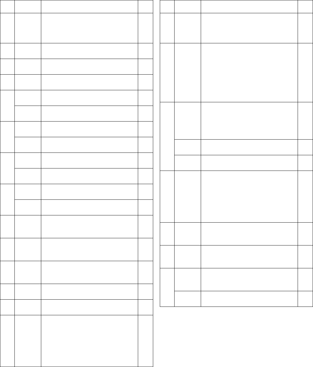
Pressure Relief Valves
Important Information regarding Pressure Relief
Valve 16C807.
Pressure Relief Valve 16C807 can only be used on
the G3 Pump. It is not intended for use with any other
products.
The pressure relief valve uses a
pressure adjustment screw (a) to
set the pressure release point. It
is not intended as a way to
relieve pressure during normal
operation, but as a protective
measure in the event there is an
unintended pressure increase in
the system. Do not use this pres-
sure relief valve a means of
relieving pressure in day-to-day,
normal cycle operation.
The pressure adjustment screw
will require periodic adjustments.
Whenever the valve is set/adjusted (after the set point is
found) it is important to ensure that the valve is not bot-
tomed out and there is at least 1/2 turn of adjustment
remaining. This is determined by turning the screw (a)
1/2 turn and then back turning it out again.
NOTE: Turning adjustment screw (a) clockwise
increases pressure.
Fuses
201
124300
CABLE, M12, 15 ft., 4 wire, straight
male to flying leads (See Wiring
Diagram, page 16)
1
124333
CABLE, M12, 15 ft., 4 wire, straight
male to female (See Wiring Dia-
gram, page 16)
1
202
124301 CONNECTOR, Eurofast, fem,
straight, 4 Pin 1
124594 CONNECTOR, Eurofast, 4 Pin
(see wiring diagram, page 17) 1
124595 CONNECTOR, Eurofast, 5 Pin
(see wiring diagram, page 17) 1
Ref Part Description Qty
a
ti15644
b
a = adjustment screw
b = locking nut
Part Description Qty
16C807
VALVE, pressure relief, 500-3500 psi
(3.44 MPa, 34.4 bar - 24.1 MPa, 241
bar), Set pressure 3000 psi + 10%
(20.68 MPa, 206.8 bar + 10%)
Included in Kit 571028
1
563156 VALVE, pressure relief, 750 psi (5.17
MPa, 51.71 bar) 1
563157 VALVE, pressure relief, 1000 psi
(6.89 MPa, 68.95 bar) 1
563158 VALVE, pressure relief, 1500 psi
(10.34 MPa, 103.42 bar) 1
563159 VALVE, pressure relief, 2000 psi
(13.78 MPa, 137.89 bar) 1
563160 VALVE, pressure relief, 2500 psi
(17.23 MPa, 172.36 bar) 1
563161 VALVE, pressure relief, 3000 psi
(20.68 MPa, 206.84 bar) 1
Part Description Qty
571039 FUSE, 12 volt DC 1
571040 FUSE, 24 volt DC 1

Parts
332291B 31
Installation and Repair Kits
Kit No. Description
Manual
Number
571026 KIT, output union, 3 pump 3A0523
571063 KIT, output union, 2 pump
571028
KIT, return to reservoir NPT,
includes pressure relief valve
16C807 3A0525
571071
KIT, return to reservoir BSPP,
includes pressure relief valve
16C807
24M478 KIT, vent valve, 12 volt DC, NO,
NPT DEU
3A0526
24M479 KIT, vent valve, 24 volt DC, NO,
NPT DEU
24M480 KIT, vent valve, 115 VAC, NO,
NPT, DIN
24N182 KIT, vent valve, 230 VAC
571036 KIT, cover with “G” label NA
571041 KIT, pump element, includes Ref
17, 18, 33 3A0533
571042 KIT, repair, 2 liter reservoir,
includes Ref 13, 36, 40
3A0534
571069
KIT, repair, 2 liter reservoir, for
models with follower plate,
includes Ref 13, 36, 40
571044
KIT, replacement, paddle, 2 liter,
for models without follower plate,
includes Ref 13, 16, 35, 57
3A0535
571045
KIT, replacement, paddle, 2 liter,
for models with follower plate,
includes Ref 13, 16, 35,40a, 42,
57
571046
KIT, replacement, paddle, 4-16
liter, for models without follower
plate, includes Ref 13, 16, 35, 57
571047
KIT, replacement, paddle, 4 liter,
for models with follower plate,
includes Ref 13, 16, 35, 57
571058 KIT, output adapter, NPT 3A0522
571070 KIT, output, adapter, BSPP
571060 KIT, fill, zerk, leakproof NA
571179 KIT, repair, reservoir oil, 2 liter
models, includes Ref 13, 36, 40b
3A0534
571182 KIT, repair, reservoir, oil 4 liter
models, includes Ref 13, 36, 40b
571183
KIT, repair, reservoir, grease, 4
liter models, includes Ref 13, 36,
40b

Technical Data
32 332291B
Technical Data
Dimensions
Maximum Working Pressure 5100 psi (35.1 MPa, 351.6 bar)
Power
100-240 VAC 88 - 264 VAC; 0.8 A current, 90 VA Power, 47/63 Hz,
Single phase, inrush/locked rotor, max 40A (1ms)
12 VDC 9 - 16 VDC; 5 A current, 60 W, inrush/locked rotor 12 A
24 VDC 18 - 32 VDC; 2.5 A current, 60 W, inrush/locked rotor 6 A
Outputs - Low Level (Dry Contact)
Contact Rating 10 Watts Maximum
Switch Rating 200 VDC Maximum
Switching Current 0.5 A Maximum
Carry Current 1.2 A Maximum
Fluid
Grease Models Grease NLGI 000 - #2
Oil Models At least 40 cSt oil.
Pumps Up to 3
Pump Output 0.12 in.3 (2 cm3) / minute per outlet - 2 spacers
0.18 in.3 (3 cm3) / minute per outlet - 1 spacer
0.25 in.3 (4 cm3) / minute per outlet - 0 spacers
Pump Outlet 1/4-18 NPSF. Mates with 1/4-18 NPT male fittings
Reservoir Size 2, 4, 8, 12, 16 Liters
IP Rating IP69K
Ambient Temps -40°F - 158°F (-40°C to 70°C)
Weight (Dry - includes power cord and plug)
Without follower plate 13.3 lbs (6.03 kg)
With follower plate 14.2 lbs (6.44 kg)
Wetted Parts nylon 6/6 (PA), trogamid T5004-060, zinc plated steel,
carbon steel, alloy steel, stainless steel, nitrile rubber
(buna-N), bronze, nickel plated alnico, chemically lubri-
cated acetal, aluminum, PTFE, Grillamid
Sound Data <60 dB
Model Height Width Depth
Inches cm Inches cm Inches cm
2L 13.25 33.65 8.00 20.32 9.00 22.86
4L 14.50 36.83 9.25 23.50 10.00 25.40
8L 18.50 47.00 9.25 23.50 10.00 25.40
12L 23.00 58.42 9.25 23.50 10.00 25.40
16L 27.50 69.85 9.25 23.50 10.00 25.40
Technical Data
332291B 33
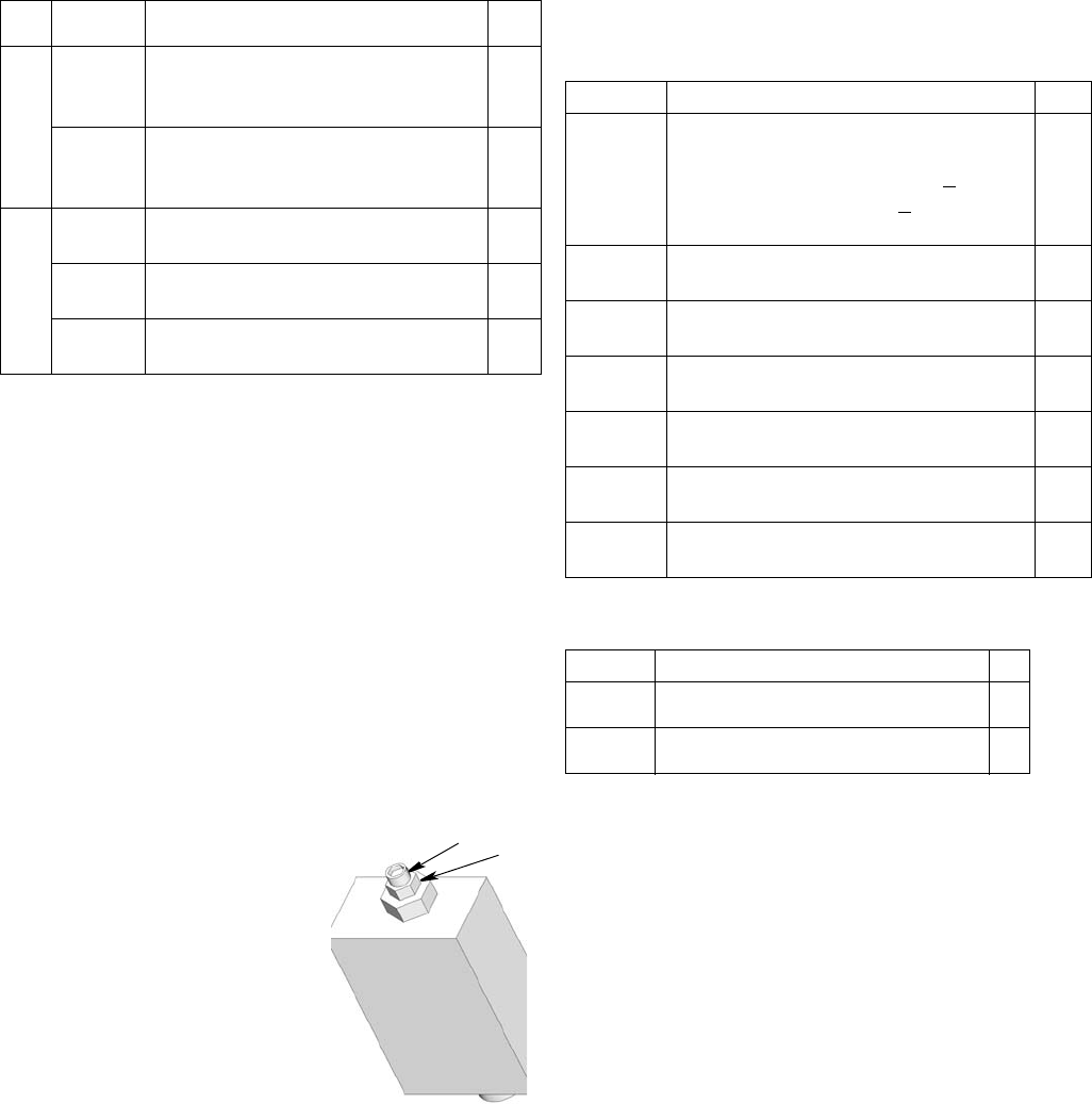
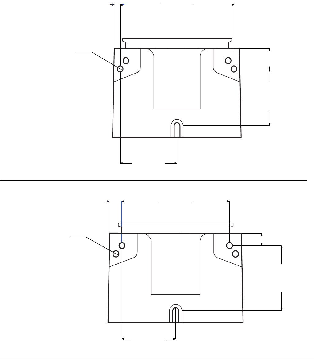
Mounting Pattern
(For correct mounting configuration, choose either Option 1 or Option 2). See P/N 126916 template.
FIG. 22
0.367inch
9.3 mm
2x Ø 0.366 inch
9.3 mm
3.544 inch
90.0 mm
7.087 inch
180.0 mm
1.180 inch
30.0 mm
3.268 inch
83.0 mm
0.722 inch
18.3 mm
2x Ø 0.366 inch
9.3 mm
3.189 inch
81.0 mm
6.378 inch
162.0 mm
3.740 inch
95.0 mm
0.708 inch
18.0 mm
Option 1
Option 2
All written and visual data contained in this document reflects the latest product information available at the time of publication.
Graco reserves the right to make changes at any time without notice.
For patent information, see www.graco.com/patents.
Original instructions. This manual contains English. MM 332291
Graco Headquarters: Minneapolis
International Offices: Belgium, China, Japan, Korea
GRACO INC. AND SUBSIDIARIES • P.O. BOX 1441 • MINNEAPOLIS MN 55440-1441 • USA
Copyright 2013, Graco Inc. All Graco manufacturing locations are registered to ISO 9001.
www.graco.com
revised April 2014
Graco Standard Warranty
Graco warrants all equipment referenced in this document which is manufactured by Graco and bearing its name to be free from defects in
material and workmanship on the date of sale to the original purchaser for use. With the exception of any special, extended, or limited warranty
published by Graco, Graco will, for a period of twelve months from the date of sale, repair or replace any part of the equipment determined by
Graco to be defective. This warranty applies only when the equipment is installed, operated and maintained in accordance with Graco’s written
recommendations.
This warranty does not cover, and Graco shall not be liable for general wear and tear, or any malfunction, damage or wear caused by faulty
installation, misapplication, abrasion, corrosion, inadequate or improper maintenance, negligence, accident, tampering, or substitution of
non-Graco component parts. Nor shall Graco be liable for malfunction, damage or wear caused by the incompatibility of Graco equipment with
structures, accessories, equipment or materials not supplied by Graco, or the improper design, manufacture, installation, operation or
maintenance of structures, accessories, equipment or materials not supplied by Graco.
This warranty is conditioned upon the prepaid return of the equipment claimed to be defective to an authorized Graco distributor for verification of
the claimed defect. If the claimed defect is verified, Graco will repair or replace free of charge any defective parts. The equipment will be returned
to the original purchaser transportation prepaid. If inspection of the equipment does not disclose any defect in material or workmanship, repairs
will be made at a reasonable charge, which charges may include the costs of parts, labor, and transportation.
THIS WARRANTY IS EXCLUSIVE, AND IS IN LIEU OF ANY OTHER WARRANTIES, EXPRESS OR IMPLIED, INCLUDING BUT NOT
LIMITED TO WARRANTY OF MERCHANTABILITY OR WARRANTY OF FITNESS FOR A PARTICULAR PURPOSE.
Graco’s sole obligation and buyer’s sole remedy for any breach of warranty shall be as set forth above. The buyer agrees that no other remedy
(including, but not limited to, incidental or consequential damages for lost profits, lost sales, injury to person or property, or any other incidental or
consequential loss) shall be available. Any action for breach of warranty must be brought within two (2) years of the date of sale.
GRACO MAKES NO WARRANTY, AND DISCLAIMS ALL IMPLIED WARRANTIES OF MERCHANTABILITY AND FITNESS FOR A
PARTICULAR PURPOSE, IN CONNECTION WITH ACCESSORIES, EQUIPMENT, MATERIALS OR COMPONENTS SOLD BUT NOT
MANUFACTURED BY GRACO. These items sold, but not manufactured by Graco (such as electric motors, switches, hose, etc.), are subject to
the warranty, if any, of their manufacturer. Graco will provide purchaser with reasonable assistance in making any claim for breach of these
warranties.
In no event will Graco be liable for indirect, incidental, special or consequential damages resulting from Graco supplying equipment hereunder, or
the furnishing, performance, or use of any products or other goods sold hereto, whether due to a breach of contract, breach of warranty, the
negligence of Graco, or otherwise.
FOR GRACO CANADA CUSTOMERS
The Parties acknowledge that they have required that the present document, as well as all documents, notices and legal proceedings entered into,
given or instituted pursuant hereto or relating directly or indirectly hereto, be drawn up in English. Les parties reconnaissent avoir convenu que la
rédaction du présente document sera en Anglais, ainsi que tous documents, avis et procédures judiciaires exécutés, donnés ou intentés, à la suite
de ou en rapport, directement ou indirectement, avec les procédures concernées.
Graco Information
For the latest information about Graco products, visit www.graco.com.
TO PLACE AN ORDER, contact your Graco distributor or call to identify the nearest distributor.
Phone: 612-623-6928 or Toll Free: 1-800-533-9655, Fax: 612-378-3590
