Graco 332305B G3 Max Automatic Lubrication Pump Users Manual 332305B, Pump, English
332305B to the manual ba70c199-fdf8-471d-ba51-b2e401ca8343
2015-04-02
: Graco Graco-332305B-G3-Max-Automatic-Lubrication-Pump-Users-Manual-685766 graco-332305b-g3-max-automatic-lubrication-pump-users-manual-685766 graco pdf
Open the PDF directly: View PDF ![]() .
.
Page Count: 76
332305B
EN
Instructions
G3 Max Automatic
Lubrication Pump
For dispensing of NLGI Grades #000 to #2 greases and oil with at least 40cSt. For
Professional Use Only.
Not approved for use in explosive atmospheres or hazardous locations.
Part Nos., page 3
5100 psi (35.1 MPa, 351.6 bar) Maximum Working Pressure
Important Safety Instructions
Read all warnings and instructions in this
manual. Save these instructions.
TI14705
Conforms to ANSI/UL 73
Certified to CAN/CSA
Std. 22.2 No 68-09
3132066
2332305B
Contents
Part / Model Numbers . . . . . . . . . . . . . . . . . . . . . . . 3
2 Liter Models . . . . . . . . . . . . . . . . . . . . . . . . . . . 3
4 Liter Models . . . . . . . . . . . . . . . . . . . . . . . . . . . 3
8 Liter Models . . . . . . . . . . . . . . . . . . . . . . . . . . . 4
12 Liter Models . . . . . . . . . . . . . . . . . . . . . . . . . . 4
16 Liter Models . . . . . . . . . . . . . . . . . . . . . . . . . . 4
Understanding the Model Number . . . . . . . . . . . 5
Warnings . . . . . . . . . . . . . . . . . . . . . . . . . . . . . . . . . 6
Installation . . . . . . . . . . . . . . . . . . . . . . . . . . . . . . . . 8
Typical Installation . . . . . . . . . . . . . . . . . . . . . . . 9
Choosing an Installation Location . . . . . . . . . . . 10
System Configuration and Wiring . . . . . . . . . . . 11
Setup . . . . . . . . . . . . . . . . . . . . . . . . . . . . . . . . . . . . 23
Connecting to Auxiliary Fittings . . . . . . . . . . . . . 23
Setting Pump Outlet Volume . . . . . . . . . . . . . . . 24
Loading Grease . . . . . . . . . . . . . . . . . . . . . . . . 24
Filling Oil Unit . . . . . . . . . . . . . . . . . . . . . . . . . . 26
Priming . . . . . . . . . . . . . . . . . . . . . . . . . . . . . . . 26
Quick Setup Guide . . . . . . . . . . . . . . . . . . . . . . . . 27
Max Model Setup . . . . . . . . . . . . . . . . . . . . . . . . . . 28
Control Panel Overview . . . . . . . . . . . . . . . . . . 28
Programming the Max Model . . . . . . . . . . . . . . 29
Pump OFF / REST Setup . . . . . . . . . . . . . . . . . 34
DMS™ Models Only . . . . . . . . . . . . . . . . . . . . . 37
Operation / Data Log . . . . . . . . . . . . . . . . . . . . . . . 39
System Event Log . . . . . . . . . . . . . . . . . . . . . . . 39
Error Log . . . . . . . . . . . . . . . . . . . . . . . . . . . . . . 40
Functional Summary . . . . . . . . . . . . . . . . . . . . . 42
Technical Summary . . . . . . . . . . . . . . . . . . . . . 44
Advanced Programming . . . . . . . . . . . . . . . . . . . . 45
Run Mode . . . . . . . . . . . . . . . . . . . . . . . . . . . . . . . . 51
Time Control . . . . . . . . . . . . . . . . . . . . . . . . . . . 51
Alarms . . . . . . . . . . . . . . . . . . . . . . . . . . . . . . . . . . 57
Fault / Warning Scenarios . . . . . . . . . . . . . . . . . 57
Troubleshooting . . . . . . . . . . . . . . . . . . . . . . . . . . 62
Maintenance . . . . . . . . . . . . . . . . . . . . . . . . . . . . . . 64
Parts - 2 Liter Models . . . . . . . . . . . . . . . . . . . . . . 65
Parts - 4 Liter and Larger Models . . . . . . . . . . . . . 66
Parts . . . . . . . . . . . . . . . . . . . . . . . . . . . . . . . . . . . . 67
Technical Data . . . . . . . . . . . . . . . . . . . . . . . . . . . . 72
Dimensions . . . . . . . . . . . . . . . . . . . . . . . . . . . . 73
Mounting Pattern . . . . . . . . . . . . . . . . . . . . . . . . 74
Graco Standard Warranty . . . . . . . . . . . . . . . . . . . 76
Graco Information . . . . . . . . . . . . . . . . . . . . . . . 76
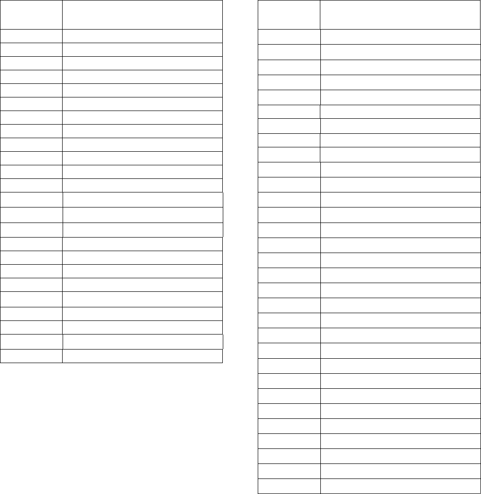
Part / Model Numbers
332305B 3
Part / Model Numbers
The Part Number is a six-digit unique number that is only used to order the G3 Pump. Directly related to this six digit
Part Number is the configured Graco Model Number. This configured number identifies the distinct features of a spe-
cific G3 Pump. To help you understand each component that makes up the Model Number see Understanding Your
Model Number, page 5. The tables below shows the relationship between each Part Number and its related Model
Number.
2 Liter Models 4 Liter Models
Part
Numbers Model Numbers
96G017 G3-G-24MX-2L0L00-10CV00R0
96G018 G3-G-24MX-2LFL00-10CV00R0
96G019 G3-G-ACMX-2L0L00-1D0V0000
96G020 G3-G-ACMX-2LFL00-1D0V0000
96G021 G3-G-12MX-2L0L00-1DMVA2R3
96G023 G3-G-24MX-2L0L00-1DMVA2R3
96G024 G3-G-24MX-2LFL00-1DMVA2R3
96G025 G3-G-ACMX-2L0L00-1DMVA2R3
96G026 G3-G-ACMX-2LFL00-1DMVA2R3
96G030 G3-G-12MX-2L0L00-10C00000
96G031 G3-G-24MX-2L0L00-10C000R0
96G032 G3-G-ACMX-2L0L00-1D000000
96G035 G3-G-12MX-2L0L05-10CV0000
96G036 G3-G-24MX-2L0L05-10CV0000
96G037 G3-G-ACMX-2L0L00-1D00A000
96G098 G3-G-12MX-2L0L00-UDMVA1R2
96G107 G3-A-24MX-2L0L00-1DMVA2R3
96G110 G3-G-24MX-2L0L00-UDMVA1R2
96G115 G3-G-24MX-2LFL00-UDMVA1R2
96G122 G3-A-ACMX-2L0L00-1DMVA2R3
96G125 G3-G-ACMX-2L0L00-UDMVA1R2
96G132 G3-G-ACMX-2LFL00-UDMVA1R2
96G174 G3-A-ACMX-2L0L00-UDMVA1R2
96G178 G3-G-24MX-2L0L00-0D00A100
Part
Numbers Model Numbers
96G088 G3-G-24MX-4L0L00-10CV00R0
96G090 G3-G-24MX-4LFL00-10CV00R0
96G092 G3-G-ACMX-4L0L00-1D0V0000
96G094 G3-G-ACMX-4LFL00-1D0V0000
96G096 G3-G-12MX-4L0L00-1DMVA2R3
96G099 G3-G-12MX-4L0L00-UDMVA1R2
96G103 G3-G-24MX-4L0L00-1DMVA2R3
96G108 G3-A-24MX-4L0L00-1DMVA2R3
96G111 G3-G-24MX-4L0L00-UDMVA1R2
96G113 G3-G-24MX-4LFL00-1DMVA2R3
96G116 G3-G-24MX-4LFL00-UDMVA1R2
96G118 G3-G-ACMX-4L0L00-1DMVA2R3
96G123 G3-A-ACMX-4L0L00-1DMVA2R3
96G126 G3-G-ACMX-4L0L00-UDMVA1R2
96G128 G3-G-ACMX-4LFL00-1DMVA2R3
96G133 G3-G-ACMX-4LFL00-UDMVA1R2
96G141 G3-G-12MX-4L0L00-10C00000
96G143 G3-G-24MX-4L0L00-10C00000
96G145 G3-G-ACMX-4L0L00-1D000000
96G151 G3-G-12MX-4L0L05-10CV0000
96G153 G3-G-12MX-4L0L05-U0CV0100
96G155 G3-G-24MX-4L0L05-10CV0000
96G157 G3-G-24MX-4L0L05-U0CV0100
96G159 G3-G-12MX-4L0L05-00C0010M
96G160 G3-G-24MX-4L0L05-00C0010M
96G161 G3-G-12MX-4L0L05-U0C0010M
96G162 G3-G-24MX-4L0L05-U0C0010M
96G175 G3-A-ACMX-4L0L00-UDMVA1R2
96G181 G3-G-24MX-4L0L03-00C00100
96G183 G3-G-ACMX-4L0L00-1D00A000
96G188 G3-A-24MX-4L0L05-U0C0010M
Part / Model Numbers
4332305B
8 Liter Models 12 Liter Models
16 Liter Models
Part
Numbers Model Numbers
96G089 G3-G-24MX-8L0L00-10CV00R0
96G093 G3-G-ACMX-8L0L00-1D0V0000
96G097 G3-G-12MX-8L0L00-1DMVA2R3
96G100 G3-G-12MX-8L0L00-UDMVA1R2
96G104 G3-G-24MX-8L0L00-1DMVA2R3
96G109 G3-A-24MX-8L0L00-1DMVA2R3
96G112 G3-G-24MX-8L0L00-UDMVA1R2
96G119 G3-G-ACMX-8L0L00-1DMVA2R3
96G124 G3-A-ACMX-8L0L00-1DMVA2R3
96G127 G3-G-ACMX-8L0L00-UDMVA1R2
96G142 G3-G-12MX-8L0L00-10C00000
96G144 G3-G-24MX-8L0L00-10C00000
96G146 G3-G-ACMX-8L0L00-1D000000
96G152 G3-G-12MX-8L0L05-10CV0000
96G154 G3-G-12MX-8L0L05-U0CV0100
96G156 G3-G-24MX-8L0L05-10CV0000
96G158 G3-G-24MX-8L0L05-U0CV0100
96G176 G3-A-ACMX-8L0L00-UDMVA1R2
96G177 G3-G-24MX-8L0L05-00C0010M
96G186 G3-A-12MX-8L0L05-U0C0010M
Part
Numbers Model Numbers
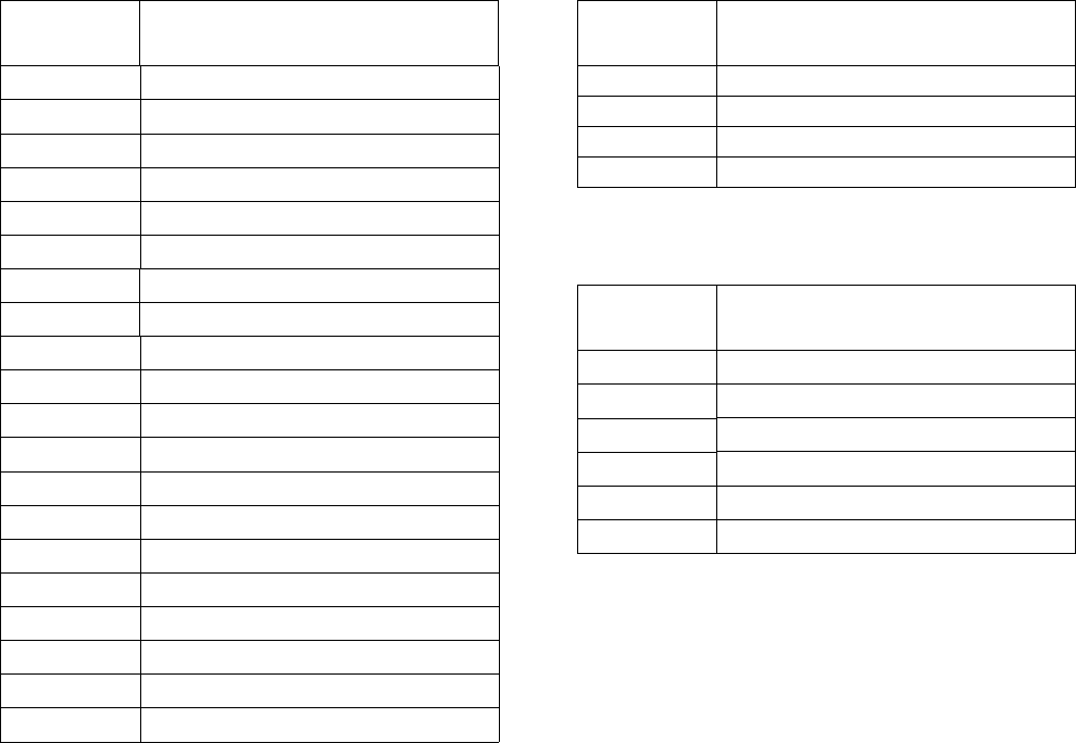
96G105 G3-G-24MX-120L00-1DMVA2R3
96G120 G3-G-ACMX-120L00-1DMVA2R3
96G164 G3-G-24MX-120L05-10CV00000
96G165 G3-G-24MX-120L05-U0CV0100
Part
Numbers Model Numbers
96G106 G3-G-24MX-160L00-1DMVA2R3
96G121 G3-G-ACMX-160L00-1DMVA2R3
96G166 G3-G-ACMX-160L00-1D0V0000
96G168 G3-G-24MX-160L05-10CV0000
96G169 G3-G-24MX-160L05-U0CV0100
96G185 G3-G-24MX-160L05-U0C0010M
Part / Model Numbers
332305B 5
Understanding the Model Number
Use the Code Sample provided below to identify each component’s location in the Model Number. The options for
each component that make up the code are provided on the lists below.
NOTE: Some pump configurations are not available. Contact Graco Customer Service or your local Graco distributor
for assistance.
G3 - G = Identifies pump as being a G3; G = Grease
G3 - A = Identifies pump as being a G3; A = Oil
Code aa: Power Source
• 12 = 12 Volts DC
• 24 = 24 Volts DC
• AC = 100 - 240 Volts AC
Code bb: Operation Control
• MX = Max (Cycle) Control
Code cc: Reservoir Capacity (Liters)
• 2L = 2 Liters
• 4L = 4 Liters
• 8L = 8 Liters
• 12 = 12 Liters
• 16 = 16 Liters
Code d: Follower Plate Installed
• F = Follower Plate Installed
• 0 = No Follower Plate
Code e: Low Level Option
• L = Low Level with Controller
• 0 = No Low Level monitoring
Code ff: Options
• 00 = No Options
• 03 = Powered Alarm Contact
• 05 = 5 Pin CPC power cable
Code g, h, i, j, k, m, n, p
NOTE: Codes g - p relate to a specific location on the
G3 pump. See FIG. 1 for these locations.
•C = CPC
•D = DIN
• 1, 2, 3 = Sensor Number
• R = Remote Manual Run
• M = Machine Count
• A = Alarm Output
• V = Vent Valve
• 0 = Not populated
• U = USB Port
G3 -G - MX
Code Sample: a a b b - c c d e f f - g h i j k m n p
FIG. 1
k
m
np
h
j
i
g
DMS
TM
Models
Warnings
6332305B
Warnings
The following warnings are for the setup, use, grounding, maintenance, and repair of this equipment. The exclama-
tion point symbol alerts you to a general warning and the hazard symbol refers to procedure-specific risk. When
these symbols appear in the body of this manual, refer back to these warnings. Additional, product-specific warnings
may be found throughout the body of this manual where applicable.
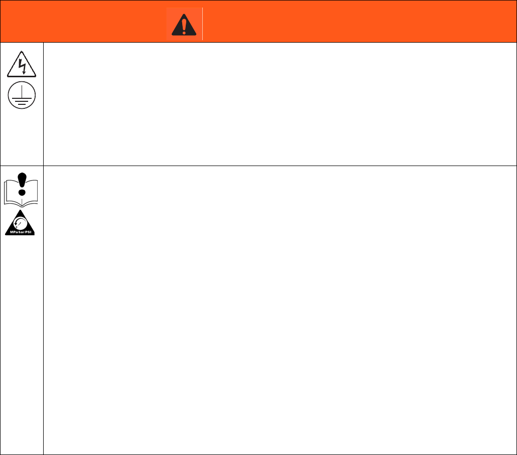
WARNING
ELECTRIC SHOCK HAZARD
This equipment must be grounded. Improper grounding, setup, or usage of the system can cause
electric shock.
• Turn off and disconnect power at main switch before disconnecting any cables and before servicing
or installing equipment.
• Connect only to grounded power source.
• All electrical wiring must be done by a qualified electrician and comply with all local codes and
regulations.
EQUIPMENT MISUSE HAZARD
Misuse can cause death or serious injury.
• Do not operate the unit when fatigued or under the influence of drugs or alcohol.
• Do not exceed the maximum working pressure or temperature rating of the lowest rated system
component. See Technical Data in all equipment manuals.
• Use fluids and solvents that are compatible with equipment wetted parts. See Technical Data in all
equipment manuals. Read fluid and solvent manufacturer’s warnings. For complete information
about your material, request MSDS from distributor or retailer.
• Turn off all equipment and follow the Pressure Relief Procedure when equipment is not in use.
• Check equipment daily. Repair or replace worn or damaged parts immediately with genuine
manufacturer’s replacement parts only.
• Do not alter or modify equipment. Alterations or modifications may void agency approvals and
create safety hazards.
• Make sure all equipment is rated and approved for the environment in which you are using it.
• Use equipment only for its intended purpose. Call your distributor for information.
• Route hoses and cables away from traffic areas, sharp edges, moving parts, and hot surfaces.
• Do not kink or over bend hoses or use hoses to pull equipment.
• Keep children and animals away from work area.
• Comply with all applicable safety regulations.
Warnings
332305B 7
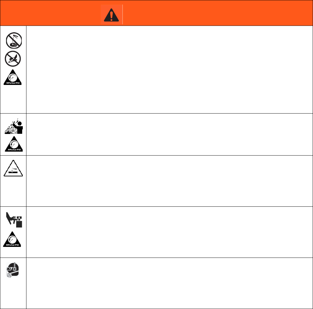
SKIN INJECTION HAZARD
High-pressure fluid from dispensing device, hose leaks, or ruptured components will pierce skin. This
may look like just a cut, but it is a serious injury that can result in amputation. Get immediate surgical
treatment.
• Do not point dispensing device at anyone or at any part of the body.
• Do not put your hand over the fluid outlet.
• Do not stop or deflect leaks with your hand, body, glove, or rag.
• Follow the Pressure Relief Procedure when you stop dispensing and before cleaning, checking, or
servicing equipment.
• Tighten all fluid connections before operating the equipment.
• Check hoses and couplings daily. Replace worn or damaged parts immediately.
PRESSURIZED EQUIPMENT HAZARD
Over-pressurization can result in equipment rupture and serious injury.
• A pressure relief valve is required at each pump outlet.
• Follow Pressure Relief Procedure in this manual before servicing.
PLASTIC PARTS CLEANING SOLVENT HAZARD
Many solvents can degrade plastic parts and cause them to fail, which could cause serious injury or
property damage.
• Use only compatible water-based solvents to clean plastic structural or pressure-containing parts.
•See Technical Data in this and all other equipment instruction manuals. Read fluid and solvent
manufacturer’s MSDSs and recommendations.
MOVING PARTS HAZARD
Moving parts can pinch, cut or amputate fingers and other body parts.
• Keep clear of moving parts.
• Do not operate equipment with protective guards or covers removed.
• Pressurized equipment can start without warning. Before checking, moving, or servicing equipment,
follow the Pressure Relief Procedure and disconnect all power sources.
PERSONAL PROTECTIVE EQUIPMENT
Wear appropriate protective equipment when in the work area to help prevent serious injury, including
eye injury, hearing loss, inhalation of toxic fumes, and burns. This protective equipment includes but is
not limited to:
• Protective eyewear, and hearing protection.
• Respirators, protective clothing, and gloves as recommended by the fluid and solvent manufacturer
WARNING
Installation
8332305B
Installation
Grounding
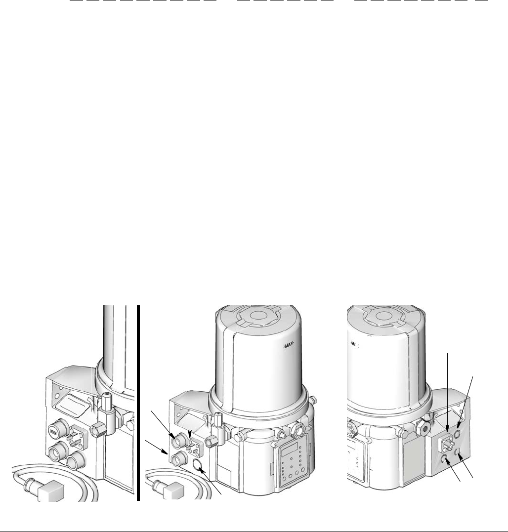
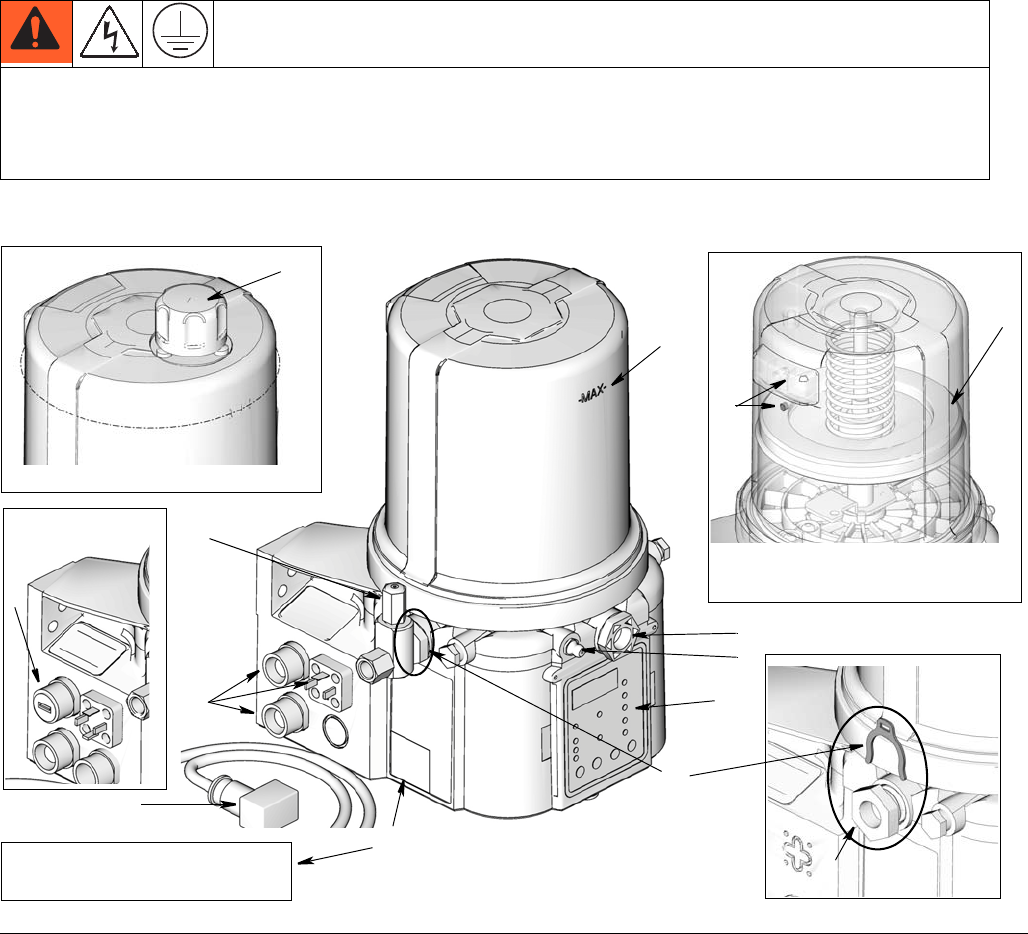
Component Identification
Key:
AReservoir
B Adjustable Pump Element (1 included. Can accommodate 3
total)
C Pressure Relief Valve (Not included / required for each outlet
- Available from Graco. See Parts, page 71.)
D Zerk Inlet Fill Fitting (1 included / grease models only)
E Pump Outlet Plug (2 included)
F Volume Control Spacers (2 included. More spacers = less
output volume per stroke) (also see FIG. 15, page 24)
G Fuse (DC models only - Not included, not shown. Available
from Graco. See Parts, page 71.)
H Control Panel
I Power / Sensor Panel (both sides; only one side shown)
J Part Number / Model Number example only shown, (see
pages 5, Understanding the Model Number, for details)
K Power Cord (DIN shown)
L Follower Plate (grease models only / not available on all
grease models)
M Vent Hole for Follower Plate (grease models only / not
available on all grease models)
N Fill cap (oil models only)
P USB Port (DMS™ Models only)
The equipment must be grounded. Grounding reduces the risk of electric shock by providing an escape wire
for the electrical current in the event of malfunction or breakdown. This product is equipped with a cord having
an equipment grounding conductor. The wire with insulation having an outer surface that is green with or
without yellow stripes is the grounding wire.
FIG. 2:
A
D
H
I
B
E
C
K
F
J
G3-G-24NC-2L0A00-L0C00000
Grease Models with Follower
Plate
L
M
96GXXX
Oil Models
N
Grease Models
DMSTM Models
P
Installation
332305B 9
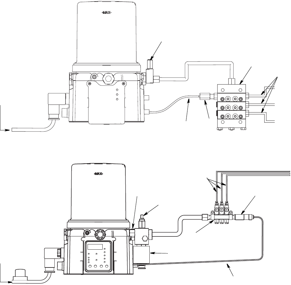
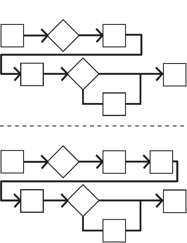
Typical Installation
Divider Installations
Injector Installations
A Connected to fuse / power
B Pressure relief valve (Not included/required for each
outlet - user supplied. See Parts, page 71)
C - Cycle indicator sensor cable (Divider Installations)
- Pressure switch cable (Injector Installations)
D - Series progressive divider valves (Divider Installations)
- Injectors (Injector Installations)
E To lube points
F - Proximity Switch (Divider Installations)
- Pressure switch (Injector Installations)
G Vent valve (Not included / available from Graco. See
Parts, beginning on page 67.)
H Return to reservoir
A
B
C
D
E
F
A
B
D
E
C
F
H
G

Installation
10 332305B
Choosing an Installation Location
• Select a location that will adequately support
the weight of the G3 Pump and lubricant, as
well as all plumbing and electrical connections.
• Refer to the two mounting hole layouts provided
in the Mounting Pattern section of this manual,
page 74.
NOTE: The two mounting hole layouts provided
in the Technical Data section show the only cor-
rect installation patterns to use for mounting the
G3. No other installation configurations should
be used.
• Use designated mounting holes and provided
configurations only.
• Always mount the G3 oil models upright.
• If the G3 grease model is going to be operated
in a tilted or inverted position for any period of
time, you must use a model that includes a fol-
lower plate, otherwise the G3 must be mounted
upright. Refer to your model number to confirm
if a follower plate was installed on your pump.
See page 5, Understanding the Model Number
to identify this character in your model number.
• Use the three fasteners (included) to secure the
G3 to the mounting surface.
• Some installations may require an additional
reservoir support bracket. Consult your Graco
distributor for assistance with this installation.
AUTOMATIC SYSTEM ACTIVATION HAZARD
Unexpected activation of the system could result in serious injury, including skin injection and amputation.
This device has an automatic timer that activates the pump lubrication system when power is connected or when
exiting the programming function. Before you install or remove the lubrication pump from the system, disconnect and
isolate all power supplies and relieve all pressure.
Installation
332305B 11
System Configuration and Wiring
If the product is permanently connected:
• it must be installed by a qualified electrician or ser-
viceman.
• it must be connected to a grounded, permanent wir-
ing system.
If an attachment plug is required in the end use
application:
• it must be rated for the product electrical specifica-
tions.
• it must be an approved, 3-wire grounding type
attachment plug.
• it must be plugged into an outlet that is properly
installed and grounded in accordance with all local
codes and ordinances.
• when repair or replacement of the power cord or
plug is required, do not connect the grounding wire
to either flat blade terminal.
Fuses
Fuse Kits are available from Graco. The following Table
identifies the correct fuse to use for your input voltage
and the corresponding Graco Kit number.
Recommendations for Using Pump in
Harsh Environments
• Use pump with CPC style power cable.
• If using a DIN style power or alarm harness with a
right angle mating connector, make sure the con-
nector does not exit the unit in the UP direction.
• Use a corrosion preventative electrical grease on all
contacts.
.Improper installation of the grounding conductor may
result in a risk of electric shock. This product must be
installed by a qualified electrician in compliance with
all state and local codes and regulations.
NOTICE
Fuses (user supplied) are required on all DC mod-
els. To avoid equipment damage:
• Never operate G3 Pump DC models without a
fuse installed.
• A fuse of the correct voltage must be installed in
line with the power entry to the system.
Input Voltage Fuse Value Graco Kit No.
12 VDC 7.5 A 571039
24 VDC 4 A 571040
Installation
12 332305B
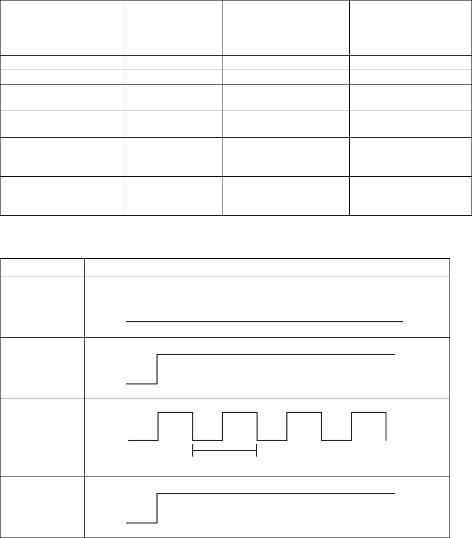
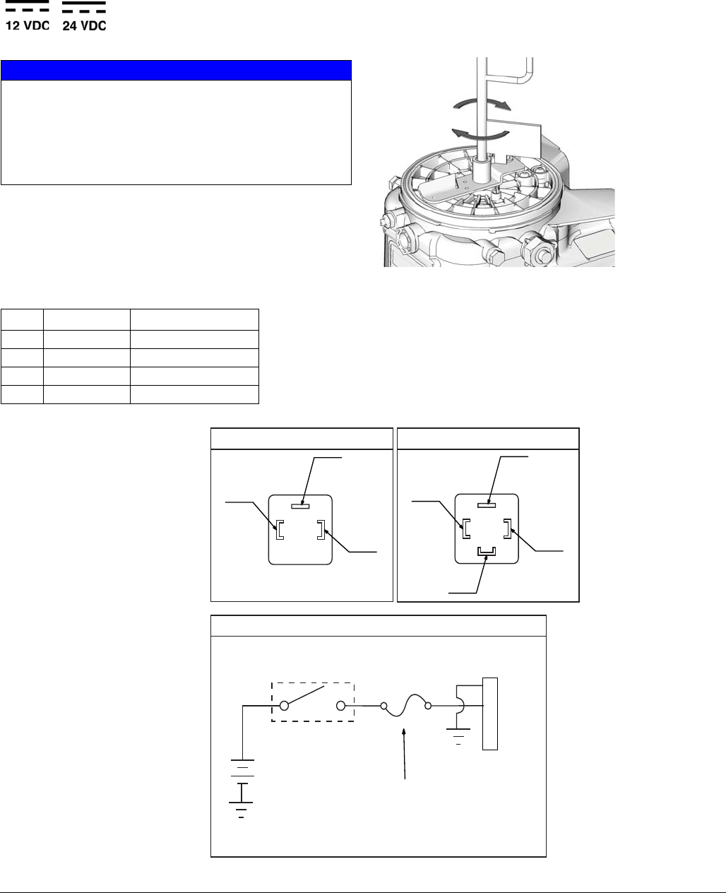
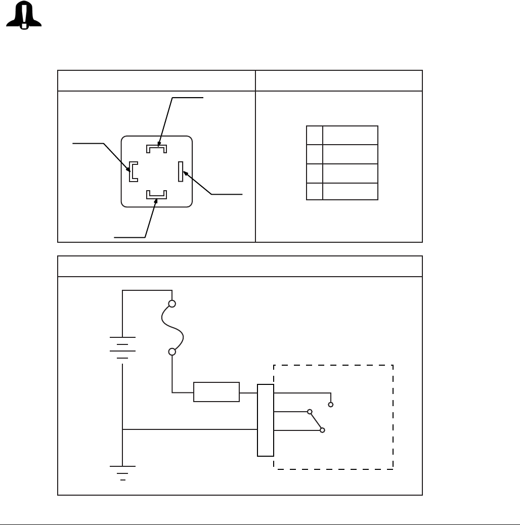
Alarm Output and Remote Illumination Response
The following tables include graphical representations of the connector as it appears on the unit, a pin-out associated
with the connector and a typical installation wiring diagram. An internal representative wiring diagram is included
where it is deemed useful.
Wire colors provided on these pages only refer to the power cable provided by Graco with this product.
Alarm Relay Response
Alarm Output
Standard Remote
Illumination
(via 5 wire CPC power
cable)
Tri-Color Remote
Illumination
(via illuminated manual run
input)
Unit in OFF Mode Deactivated (off) Off Off
Unit in ON Mode Deactivated (off) On Green
Warning Condition Activated (on) Toggles On and Off once
per second Yellow
Fault Condition Toggles On and Off
once per second
Toggles On and Off once
per second Red
Fault Condition
(Advanced Programming
Setting A7 OFF)
Toggles On and Off
once per second
Toggles On and Off once
per second Red
Fault Condition
(Advanced Programming
Setting A7 ON)
Activated (on) Toggles On and Off once
per second Red
Output Tied to Common
No Faults or
Warnings
Warning
Fault
(Advanced
Programming A7
OFF)
Fault
(Advanced
Programming
Setting A7 ON)
N.O.
N.C.
N.O.
N.C.
N.O.
N.C.
1 second
N.O.
N.C.
Installation
332305B 13
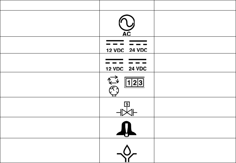
Wiring and Installation Diagrams
The following Table identifies the wiring and installation diagrams provided in this manual.
Diagram Symbol Page #
Power DIN AC 14
Power DIN DC 15
Power CPC DC 16
Inputs (M12) 18
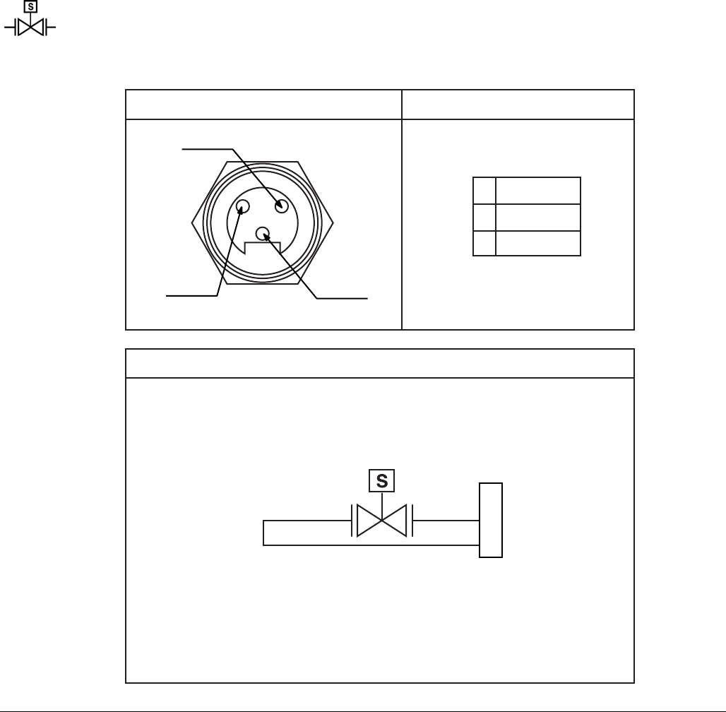
Vent Valve Outputs 19
Alarm Outputs 20
Illuminated Manual Run Input Kits: 571030, 571031,
571032, 571033
Installation
14 332305B
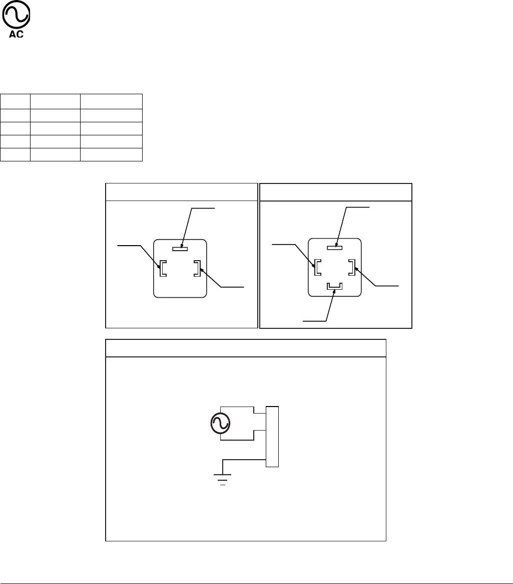
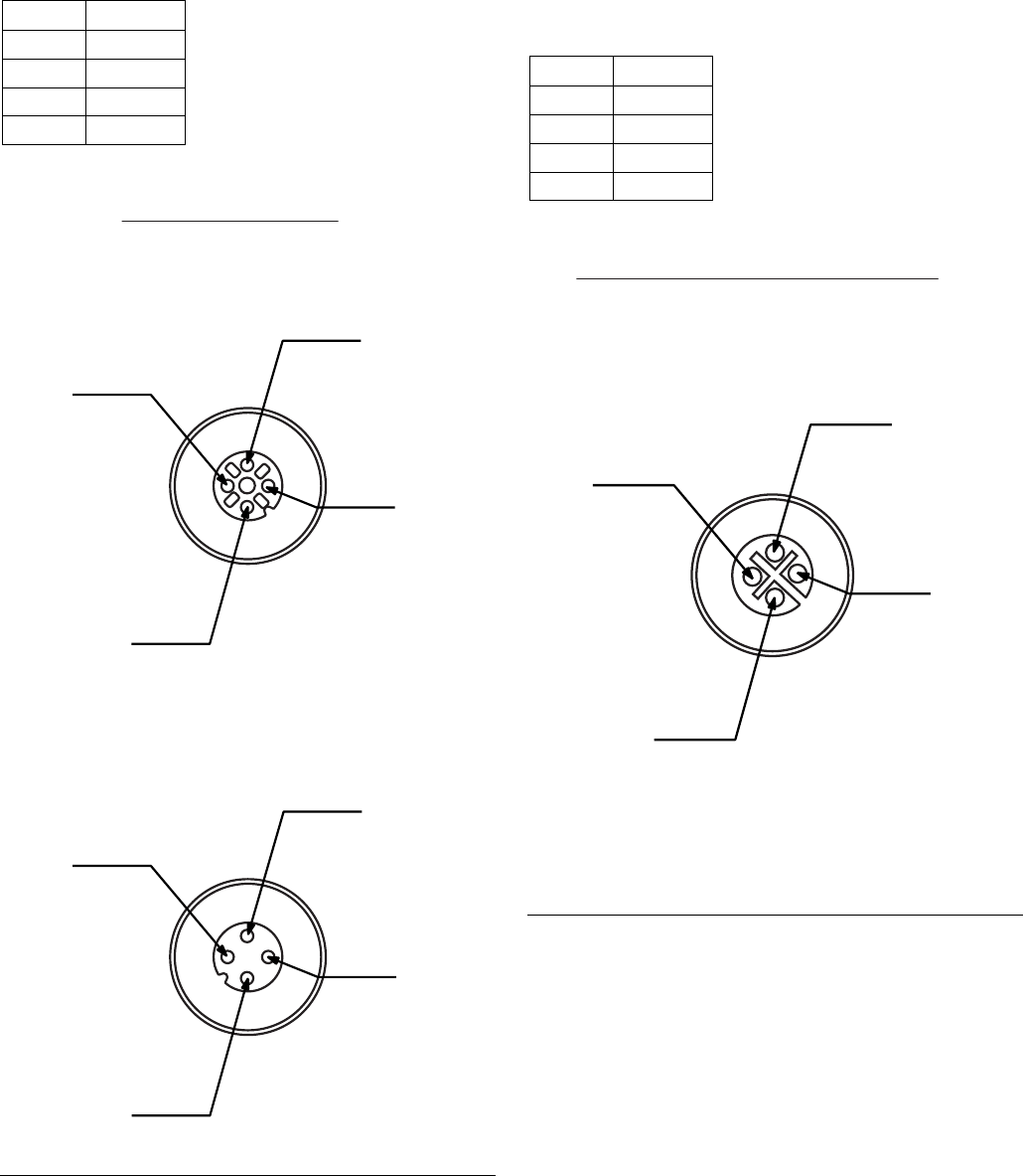
Power DIN AC - 15 foot: Part No. 16U790
Pin and Related Wire Color (FIG. 3)
Pin Pin Name Color
1 Line Black
2 NEUTRAL White
3 Not Used Not Used
4GROUND Green
FIG. 3
(4)
(2)
(1)
1
2
3
4
Example Wiring Diagram
Connector on Housing Connector on Cable
(4)
(1)
(3)
(2)
Installation
332305B 15
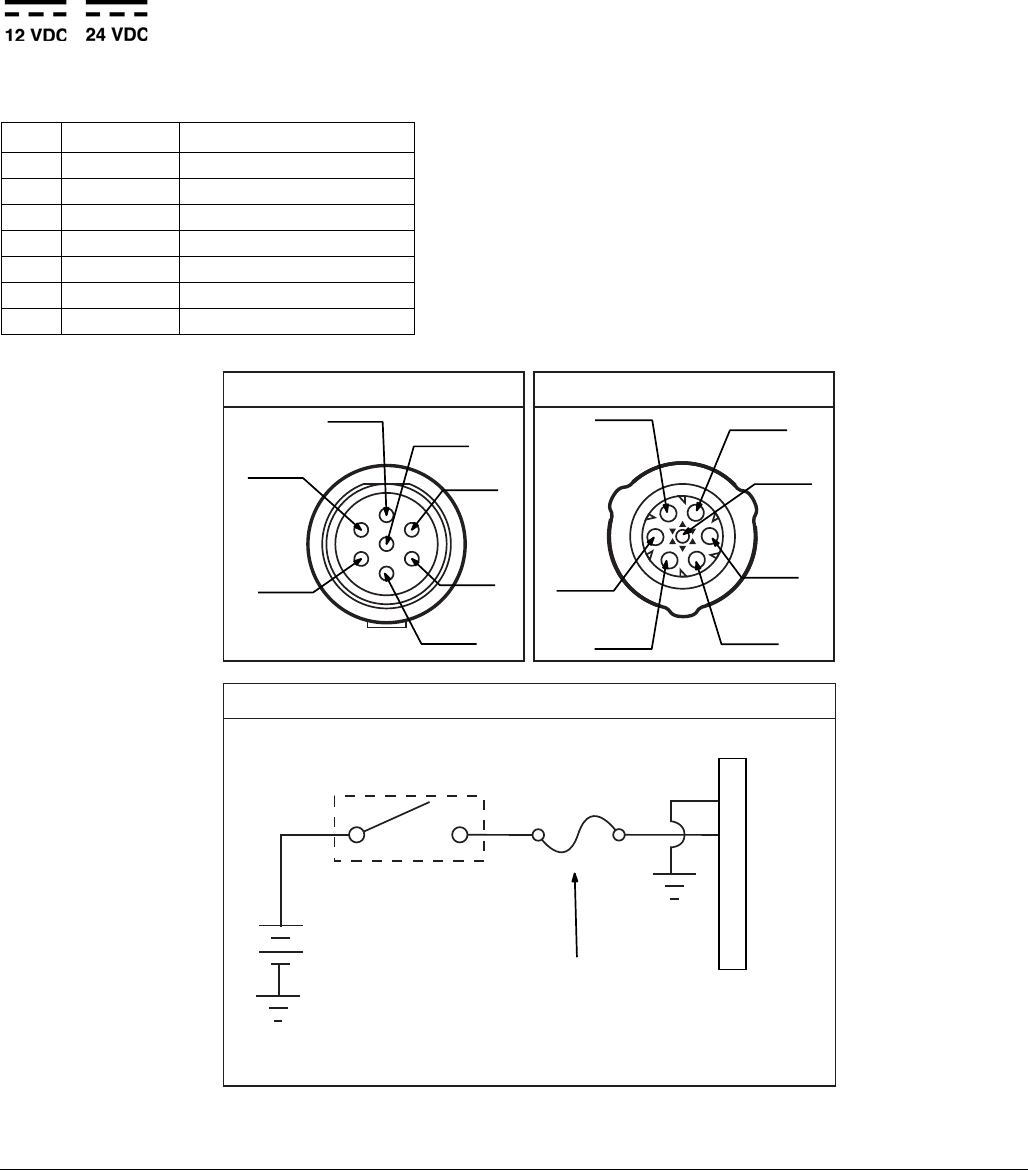
Power DIN DC - 15 foot: Part No. 16U790
Pin and Related Wire Color (FIG. 4)
NOTICE
Be sure when power is applied that stirring paddle
rotates clockwise (when viewed from the top). If it is
wired incorrectly paddle could rotate counter-clockwise
which will damage the pump’s internal components. If
this happens, stop the pump immediately and wire unit
correctly.
Pin Pin Name Color
1-VDC Black
2+VDC White
3 Not Used Not Used
4 Not Used Green
FIG. 4
Ignition Switch
Fuse
1
2
3
4
Example Wiring Diagram
Connector on Housing
12V-pump - 7.5A - Graco kit #571039
24V pump - 4A - Graco kit #571040
(4)
(2)
(1)
Connector on Cable
(4)
(1)
(3)
(2)
Installation
16 332305B
Power CPC DC -15 foot: Part No. 126217
Pin and Related Wire Color (FIG. 6)
Pin Pin Name Color
1 Not Used Not Used
2-VDC Black
3+VDC White
4 Not Used Not Used
5 Not Used Not Used
6 Not Used Not Used
7 Not Used Green
FIG. 5
(1)
(2)
(3)
(4)
(5)
(6)
(7)
Example Wiring Diagram
Connector on Housing Connector on Cable
Ignition Switch
Fuse
1
2
3
4
5
6
7
12V-pump - 7.5A - Graco kit #571039
24V pump - 4A - Graco kit #571040
(1)
(3)
(2)
(7)
(6) (5)
(4)
Installation
332305B 17
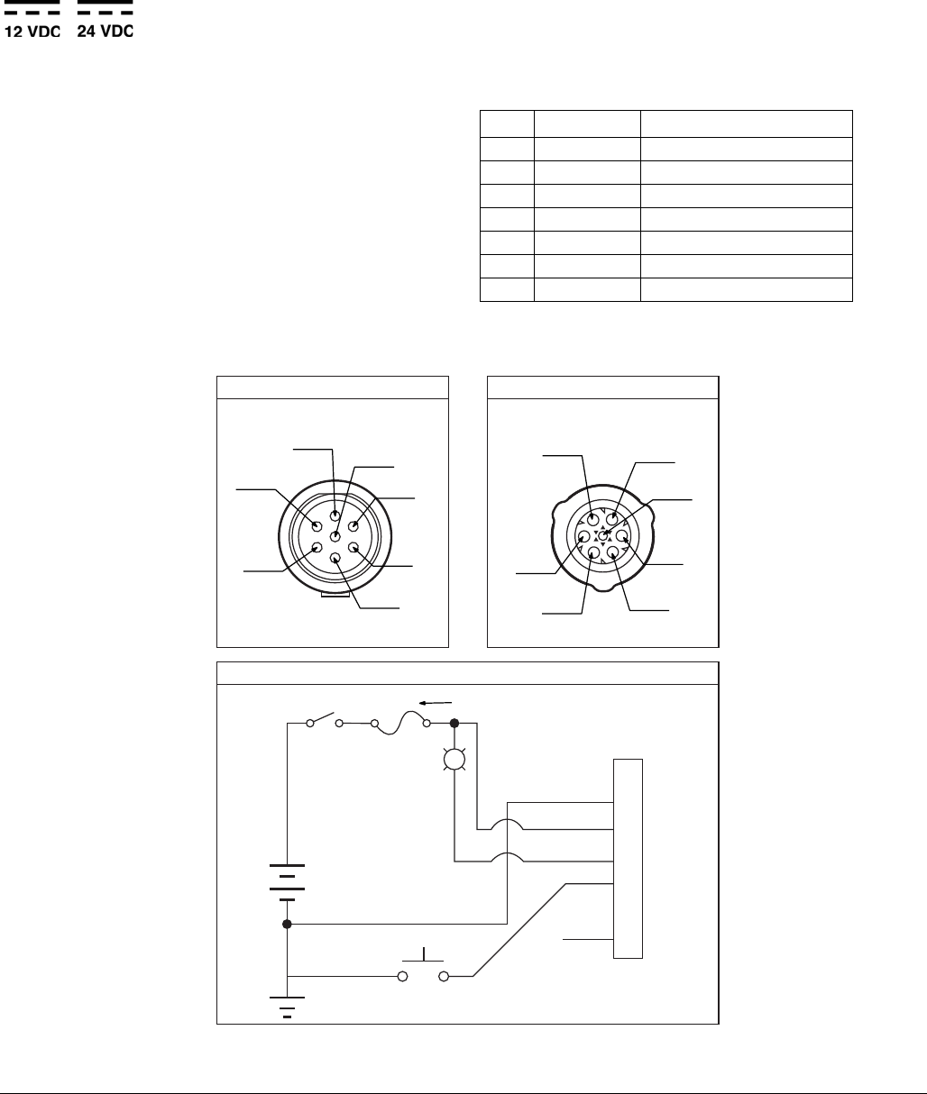
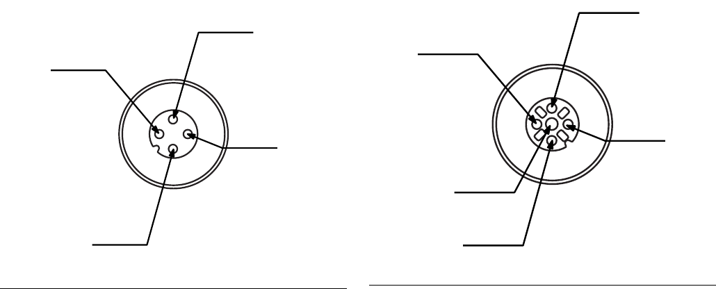
Power CPC DC - 5 Wire
Part No.: 126218: 15 ft (4.5 m)
Part No.: 126219: 20 ft (6.1 m)
Part No.: 126220: 30 ft (9.1 m)
NOTE: An Illuminated Remote Run Button Kit: 571030,
571031 for starting a manual run cycle if used in con-
junction with a 5-wire CPC cable, is available from
Graco. Contact your local Graco distributor or Graco
Customer Service for additional information about these
kits.
Pin and Related Wire Color (FIG. 6)
Pin Pin Name Color
1 Not Used Not Used
2-VDC Black
3+VDC Red
4LIGHT White
5 MANUAL ORANGE
6 Not Used Not Used
7 Not Used Green
FIG. 6
(1)
(2)
(3)
(4)
(5)
(6)
(7)
1
2
3
4
5
6
7
L
Fuse 12V-pump - 7.5A - Graco kit #571039
24V pump - 4A - Graco kit #571040
Example Wiring Diagram
Connector on Housing Connector on Cable
(1)
(3)
(2)
(7)
(6) (5)
(4)
Installation
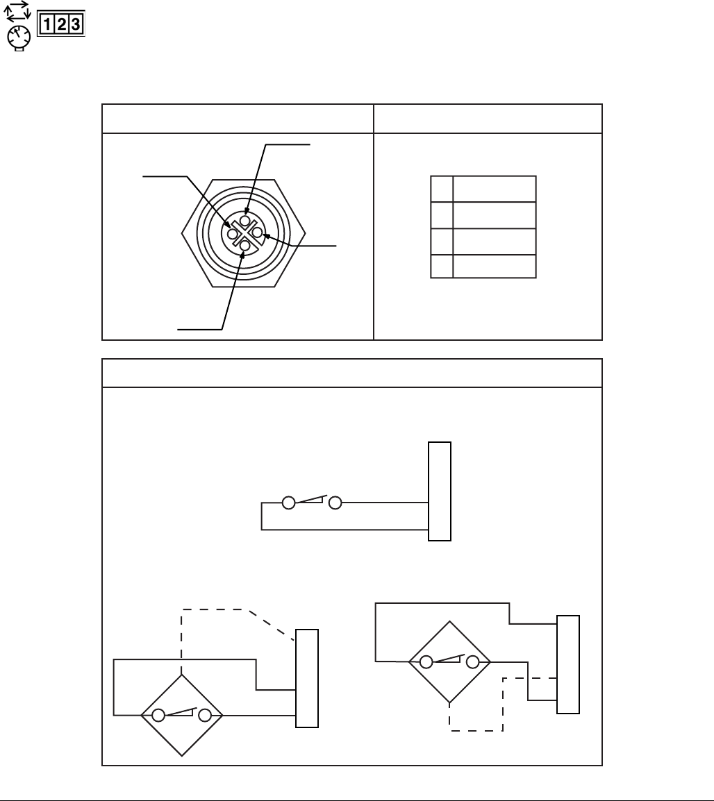
332305B 21
Part No. 124333: Cable Pin Out (M12)
Wire Colors
Part No. 124300: Field Wireable Pin Out
(M12)
Wire Colors
Item No. Color
1Brown
2White
3Blue
4Black
FIG. 10
Item No. Color
1Brown
2White
3Blue
4Black
FIG. 11
Installation
22 332305B
Part No. 124594: 4 Pin Eurofast Field
Wireable Connector
Part No. 124595: 5 Pin Eurofast Field
Wireable Connector
FIG. 12
FIG. 13
Setup
332305B 23
Setup
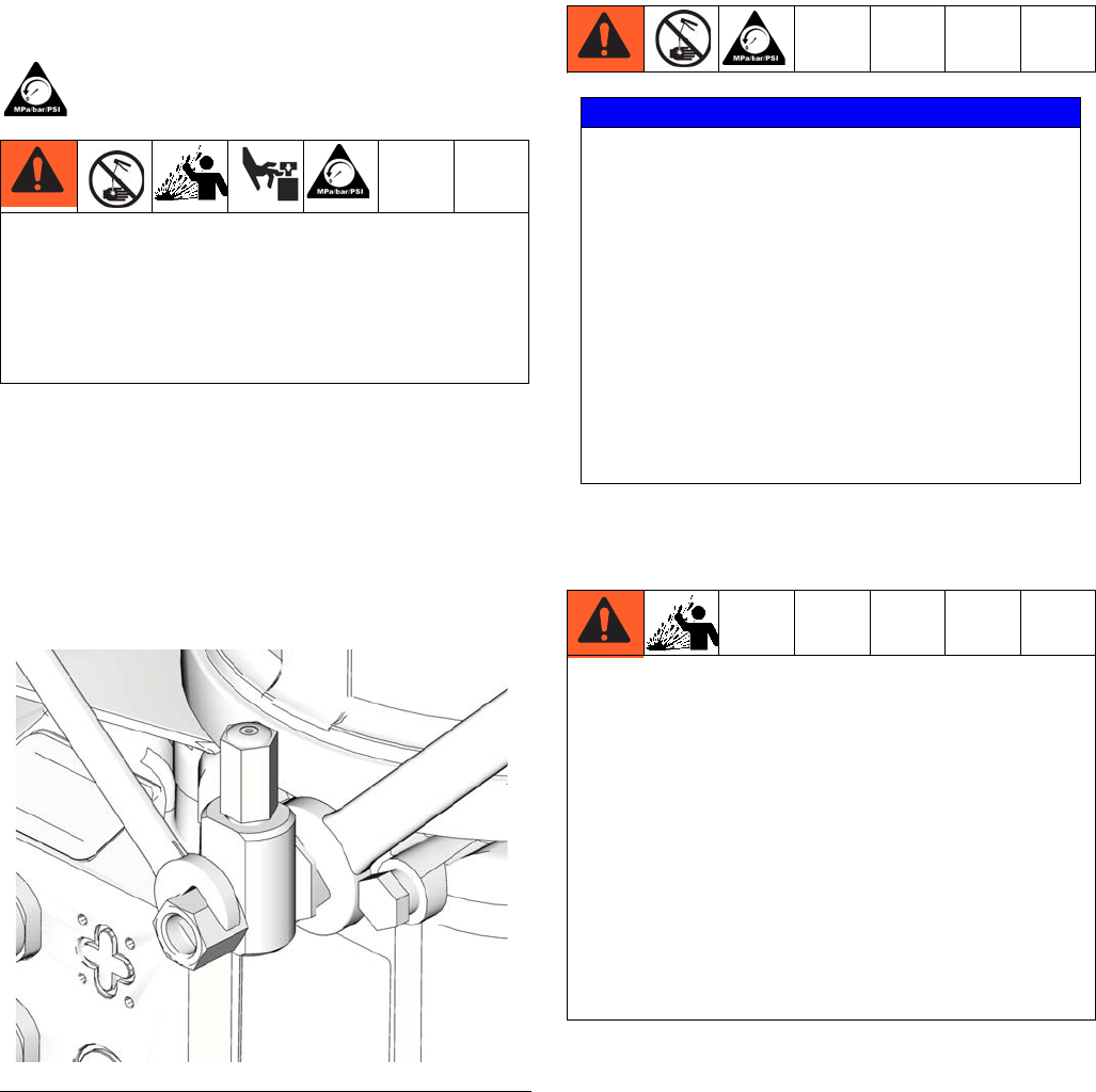
Pressure Relief
Follow the Pressure Relief Procedure whenever
you see this symbol.
Relieve pressure in system using two wrenches
working in opposite directions on pump element and
pump element fitting to slowly loosen fitting only until
fitting is loose and no more lubricant or air is leaking
from fitting.
NOTE: When loosening pump element fitting, do NOT
loosen pump element. Loosening pump element will
change the output volume.
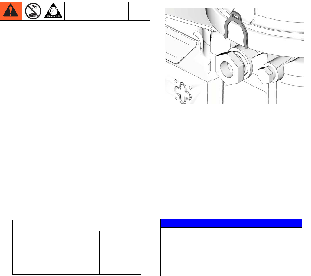
Connecting to Auxiliary Fittings
Pressure Relief Valves
NOTE: A pressure relief valve can be purchased from
Graco. See Parts, page 71.
This equipment stays pressurized until pressure is
manually relieved. To help prevent serious injury
from pressurized fluid, such as skin injection,
splashing fluid and moving parts, follow the Pressure
Relief Procedure when you stop spraying and before
cleaning, checking, or servicing the equipment.
FIG. 14
NOTICE
Do not attach unsupported equipment to auxiliary
fittings such as fill ports and pump element. Attach-
ing unsupported equipment to these fitting can
result in irreparable housing damage.
• Always use two wrenches working in opposite
directions when connecting anything to pump
element or auxiliary fittings. See FIG. 14 for an
example.
• Torque pump element fittings to 50 in. lbs (5.6
N•m).
• When connecting pump element into housing
torque to 50 in. lbs (5.6 N•m).
To prevent over-pressurization, which can result in
equipment rupture and serious injury, a pressure relief
valve appropriate for the lubrication system must be
installed close to every pump outlet to alleviate unin-
tended pressure rises in the system and protect the G3
pump from damage.
• Only use a pressure relief valve that is rated for no
more than the working pressure of the G3 pump it
is installed on. See Technical Data, page 66.
• Install a pressure relief valve close to every pump
outlet; before any auxiliary fitting.
Setup
24 332305B
Setting Pump Outlet Volume
NOTE:
• Before making any adjustments to pump volume,
Relieve Pressure following procedure on page 23.
• Only use Graco supplied spacers to control output
volume.
• It may be necessary to repeat this outlet volume
setup procedure after the pump is operating to
re-adjust the volume of dispensed fluids.
1. Use a wrench to turn pump element counter-clock-
wise to loosen. Do not remove entire pump element.
Only back pump element out enough to allow
spacer to be slid on or off.
2. If needed, remove or insert spacers to achieve
required pump output volume. A tool may be
needed to facilitate removal.
Pump volume control is set using either no (0) spac-
ers, 1 or 2 spacers (FIG. 15).
Do not use more than 2 spacers to adjust output vol-
ume.
NOTE:
• The amount of dispensed volume can vary depend-
ing on external conditions such as lubricant tem-
perature and back pressure from downstream
connections.
• Use of these volume adjustment in conjunction with
setting the ON time of the pump will allow for control
of the output volume.
• Use these volume adjustments as a starting point
and adjust as necessary to ensure desired lubrica-
tion dispense.
3. Tighten pump element fitting. Torque fitting to 50 in.
lbs (5.6 N•m).
Loading Grease
To ensure optimal performance from the G3:
• Only use NLGI #000 - #2 greases appropriate for
your application, automatic dispensing, and the
equipment’s operating temperature. Consult with
machine and lube manufacturer for details.
• The reservoir can be filled using a hand operated
pump, pneumatic pump or electric transfer pump.
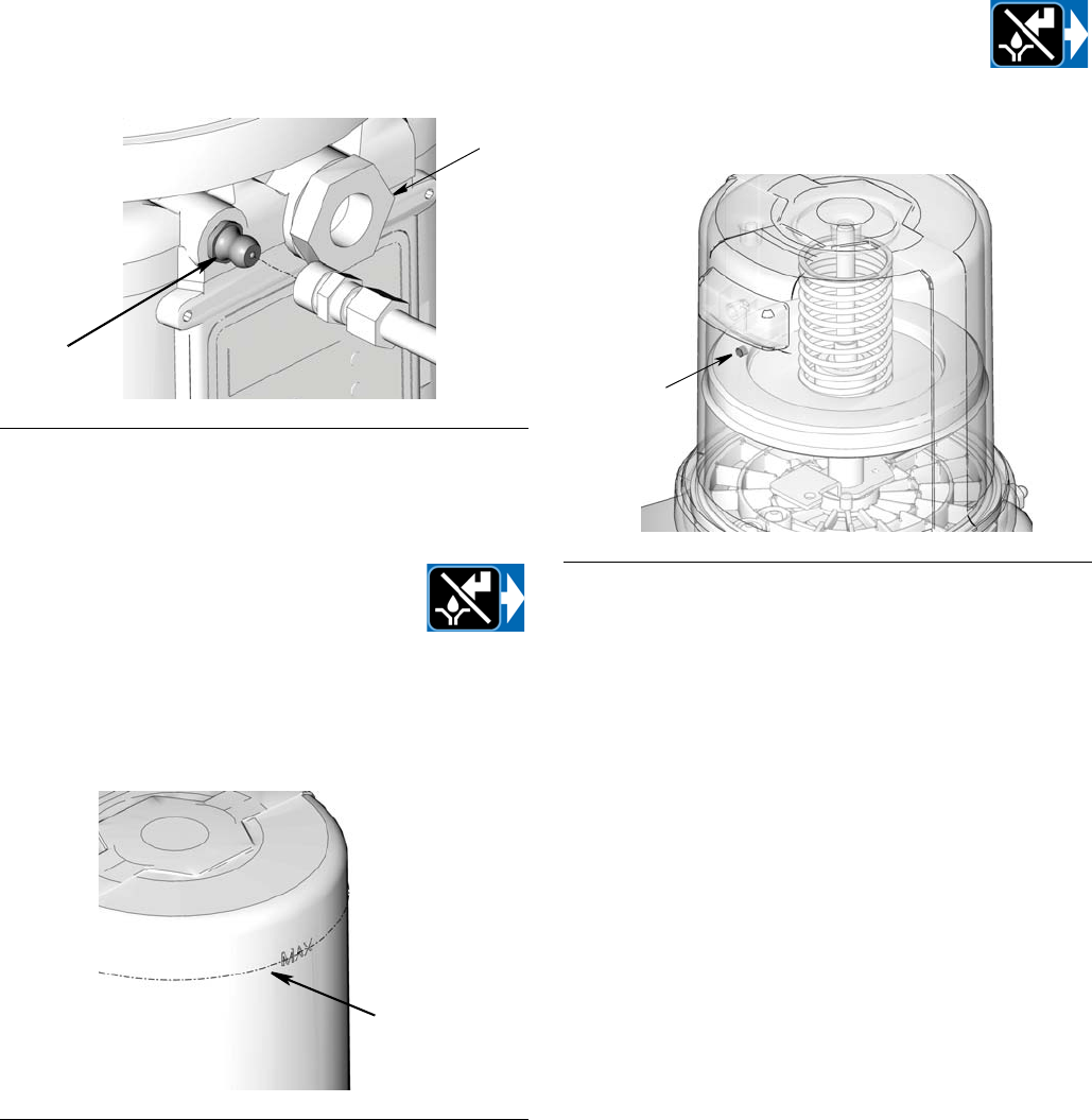
• Do not overfill (FIG. 17).
• Do not operate G3 without reservoir attached.
No. Spacers
Output Volume / Minute
cubic inches cubic cm
20.122
10.183
00.254
FIG. 15
NOTICE
• Always clean fitting (D) with a clean dry cloth
prior to filling reservoir. Dirt and/or debris can
damage pump and/or lubrication system.
• Care must be used when filling the reservoir
using a pneumatic or electric transfer pump to
not pressurize and break the reservoir.
Setup
332305B 25
Models without a follower plate:
1. Connect fill hose to inlet fitting (FIG. 16).
2. For higher viscosity fluids, start pump to rotate stir-
ring paddle during fill to prevent air pockets from
forming in grease.
To start the pump press the manual run
button.
3. Fill reservoir with NLGI grease to max
fill line.
NOTE: Vent port, located in rear of reservoir, should not
be used as an overfill port/indicator.
4. Remove fill hose.
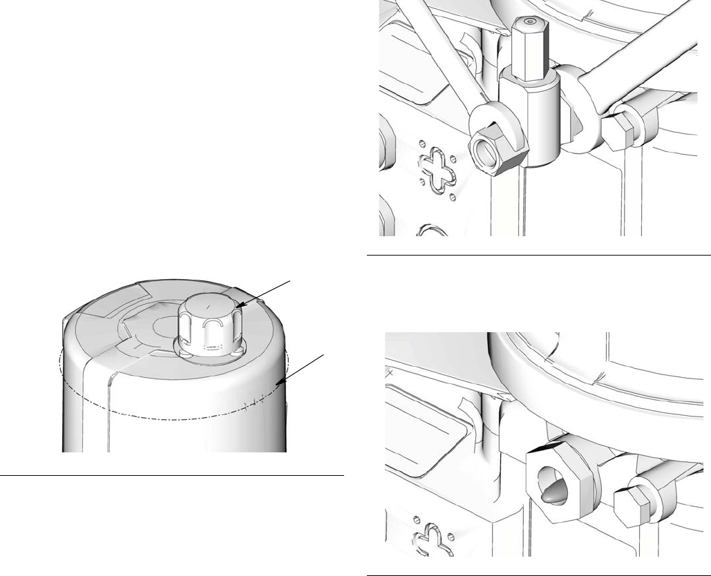
Models with a follower plate:
1. Connect fill hose to inlet fitting (FIG. 16).
2. For higher viscosity fluids, start pump to rotate stir-
ring paddle during fill to prevent air pockets from
forming in grease.
To start the pump press the manual run
button.
3. Fill reservoir with grease until seal of
follower plate breaches the vent hole (FIG. 18) and
the majority of air is expelled from the reservoir.
NOTE: Vent port, located in rear of reservoir, should not
be used as an overfill port/indicator.
4. Remove fill hose.
Changing Greases
When changing greases, always use compatible fluids
or greases.
FIG. 16
FIG. 17
D
E
max fill line
FIG. 18
vent hole
Setup
26 332305B
Filling Oil Unit
• Only use oil appropriate for your application, auto-
matic dispensing, and the equipment’s operating
temperature. Consult with machine and lube manu-
facturer for details.
• The reservoir can be filled using a hand operated
pump, pneumatic pump or electric transfer pump.
• Do not overfill (FIG. 19).
• Do not operate G3 without reservoir attached.
• Only use oils with viscosity at least 40 cSt.
1. Remove fill cap (a).
2. Pour oil into reservoir to fill line (b).
3. Replace fill cap. Hand tighten cap, securely.
Priming
NOTE: It is not necessary to prime pump every time
pump is filled with lubricant.
Pump only requires priming the first time it is used or if it
is allowed to run dry.
1. Loosen pump element fitting (FIG. 20).
NOTE: When loosening pump element fitting, do NOT
loosen pump element. Loosening pump element will
change the output volume
2. Only run pump until air is no longer dispensed with
the lubricant coming out of element fitting (FIG. 21).
3. Tighten pump element fitting using two wrenches
working in opposite directions (FIG. 20).
FIG. 19
a
b
FIG. 20
FIG. 21
Quick Setup Guide
332305B 27
Quick Setup Guide
Max Model Setup
28 332305B
Max Model Setup
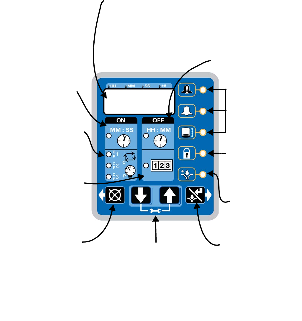
Control Panel Overview (FIG. 22)
NOTE: Programming instructions begin on page 29.
FIG. 22
DISPLAY
•A blinking LED under HH, MM, SS
or ## identifies type of measurement
unit you are setting; i.e., HH is
hours.
•A blinking number on the display
indicates the G3 is in SETUP
MODE.
•In RUN MODE displayed numbers
count up or down. See Time ON and
Time OFF.
ON TIME/BACKUP TIME
•LED lights when ON
Time/Backup Time is running.
•Display shows time as MM:SS
(minutes and seconds).
i.e., 08:30 is 8 minutes: 30 sec-
onds.
•Sets the limits for the amount
of time to complete a cycle or
build up pressure before a
warning is activated.
•Counts down from a set time to
zero.
OFF TIME/BACKUP TIME
•LED lights when OFF
Time/Backup Time is used to con-
trol Pump OFF function.
•Value is entered in HH:M.
•Displays in HH:MM (hours and
minutes) when > 1 hour.
•Times pump rest between cycles.
•Counts down from set time to
zero.
•Can be set up to use as a backup
for Machine Count control.
ALARM ICONS
LED next to icon lights when a
fault / warning event occurs
during a run cycle. See page 57
for a complete description of
these alarm scenarios.
PIN ICON
•LED next to icon lights indi-
cating PIN is required to
enter setup.
•In SETUP MODE LED
lights when setting up the
PIN.
PRELUBE
LED next to icon lights indicat-
ing LED lights when Prelube
function is enabled.
LEFT DIRECTION ARROW /
RESET
•In ADVANCED and SETUP
MODES, moves cursor in dis-
play one field to the left.
•In RUN MODE: single press
clears warning.
•In ALARM MODE: pressing and
holding for 3 seconds clears
fault / warning and switches
cycle to OFF MODE.
RIGHT DIRECTION ARROW /
MANUAL RUN / ENTER
•In SETUP MODE, saves
entry, moves cursor in display
one field to the right or to the
next setup step.
•In RUN MODE starts a man-
ual run cycle.
UP and DOWN ARROW
•Hold both the UP and DOWN ARROW but-
tons down together for 3 seconds to enter
SETUP MODE.
•In SETUP MODE, increases or decreases
number values shown in display.
CYCLE / PRESSURE SETUP
•Sets either Cycle (C) or Pressure
(P) Monitoring limits for up to 3
sensors.
•Each sensor is set up and con-
trolled independently.
MACHINE COUNT
•LED lights when Machine Count
is used to control Pump OFF
function.
•Counts independent machine
operations with a sensor to con-
trol Pump Off duration.
•Time OFF function can be used
as a backup for Machine Count.
Max Model Setup
332305B 29
Programming the Max Model
Powering Units With Controllers
By default, units with controllers are set to
operate in a timed mode with 1 minute of
ON time and 8 hours of OFF time. The unit
should be powered up in OFF mode,
counting down from the 8 hours. If the unit powers up in
ON mode and has not been primed, hold the reset but-
ton located on the control panel (example shown on the
right) for 1 second to move to the OFF mode.
NOTE:
• A blinking number on the display indicates the G3 is
in SETUP MODE.
• In RUN MODE numbers on the display do not blink.
• After 60 seconds of no activity, the device returns to
RUN MODE in the OFF Time cycle and the OFF
Time restarts counting down the total programmed
amount of time. It does not resume the countdown
from the point where the cycle was interrupted when
you entered SETUP MODE.
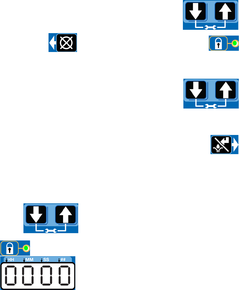
Entering Setup Mode
Press both the UP and DOWN
ARROW buttons together for 3
seconds to enter the SETUP
MODE.
NOTE: If the lock LED is
lit after entering Setup
Mode and four 0000’s
are displayed, the unit
has a PIN Code lock out
enabled. See the follow-
ing section: Entering a
PIN Code to Access
Setup Mode.
Entering a PIN Code to Access Setup Mode
The G3 controller does not require a user to provide a
PIN code to access the programming features of the
unit. However, Graco understands that some users may
want to protect the programming settings and therefore,
an option for adding PIN Code authorization is available.
The instructions for setting up PIN Code Authorization
are provided in the Advanced Programming section of
this manual. See page 46.
To enter the PIN Code:
1. Press both the UP and
DOWN ARROW buttons for 3
seconds.
2. The LED next to the LOCK ICON on
the display lights and the 4 zeros
appear on the display indicating the
system requires a PIN Code entry to run the G3 in
SETUP MODE.
3. The cursor is automatically
positioned to enter the first
character of the PIN Code.
Use the UP and DOWN
ARROW buttons to move up
and down through the numbers 0-9 until the first
number in the PIN code is displayed in the field.
4. Press the ENTER button to set the num-
ber. The cursor automatically moves to
the next number field.
5. Repeat steps 3 and 4 for each PIN Code prompt
field.
If the PIN Code you entered is correct, the first editable
character on the display will flash.
NOTE: A blinking field on the display indicates the G3 is
in SETUP MODE. In RUN MODE numbers on the dis-
play will not blink.
Max Model Setup
30 332305B
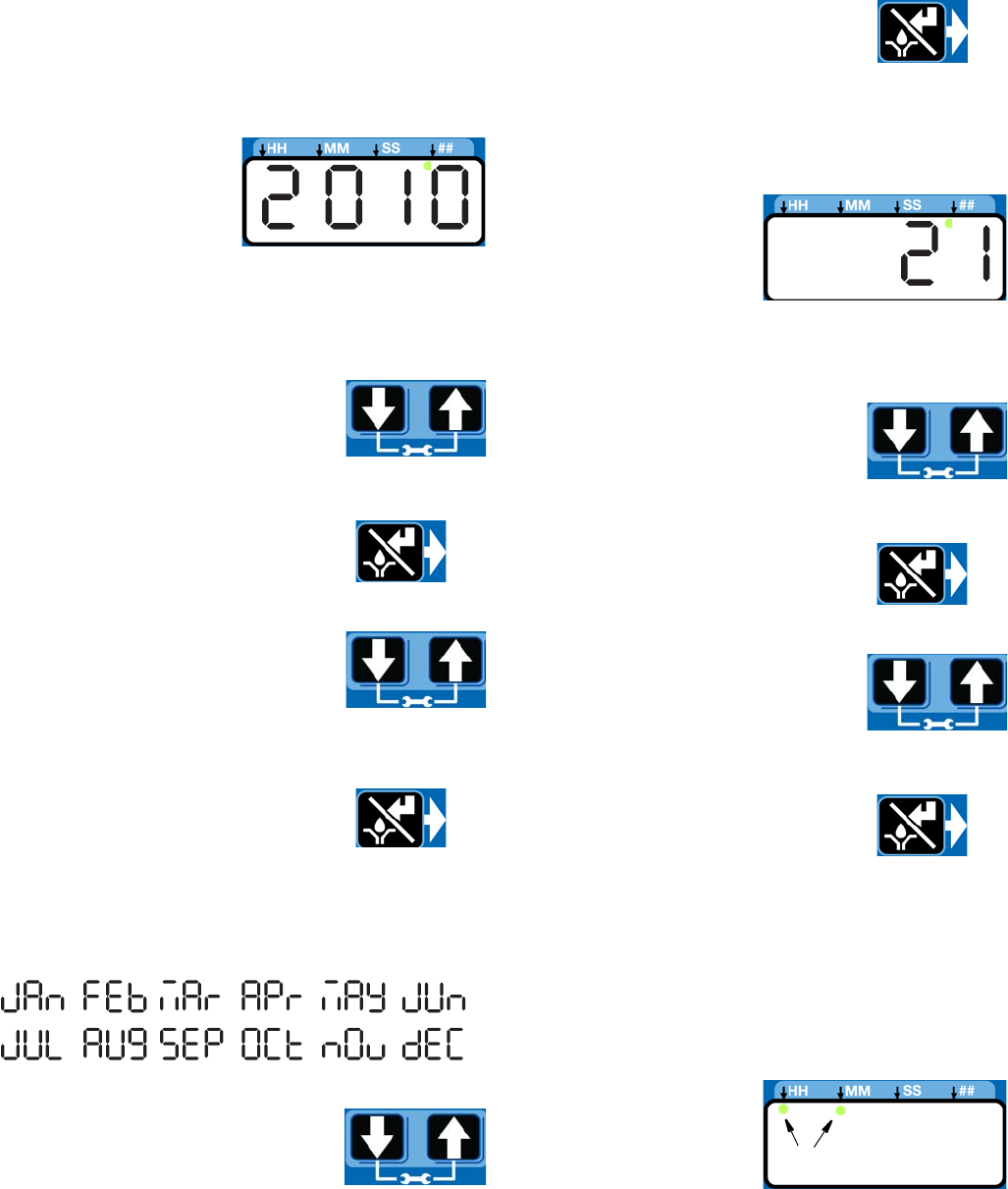
Setting the Real Time Clock
DMS™ Equipped Models Only
NOTE: Set the real time clock prior to plugging the USB
flash drive into the pump.
Enter the Year:
• The year displays.
The first programma-
ble character, the
decade, blinks indi-
cating the device is
ready to program the
decade digit of the year.
• The LED under the # sign lights while setting the
year.
1. Use the UP and DOWN arrow but-
tons to move up and down through
the number 0-9 until the number
for the current decade is displayed
in the field.
2. Press the ENTER button to set the
decade number. The cursor auto-
matically moves to the next field, the
year number.
3. Use the UP and DOWN arrow but-
tons to move up and down through
the number 0-9 until the number
for the current year is displayed in
the field.
4. Press the ENTER button to set the
year number.
The 3-character month displays indicating the G3 is
now ready to program the month.
Enter the Month:
1. Set the 3 character month by using
the UP and DOWN ARROW but-
tons to move up and down through
the list of months until the current month is dis-
played in the field.
2. Press the ENTER button to set the
month.
The 2-digit date displays indicating the G3 is now
ready to program the date.
Enter the 2-digit Date:
The first programmable
character of the 2-digit
date blinks indicating the
device is ready to pro-
gram the first digit of the
date.
The LED under the # sign lights while setting the date.
1. Use the UP and DOWN ARROW
buttons to move up and down
through the numbers 0-3 until the
first digit of the date is displayed in
the field.
2. Press the ENTER button to accept
the selection. The cursor automati-
cally moves to the second digit of
the date.
3. Use the UP and DOWN ARROW
buttons to move up and down
through the numbers 0-9 until the
second digit of the date is dis-
played in the field.
4. Press the ENTER button to set the
date.
The time displays indicating the G3 is now ready to
program the time.
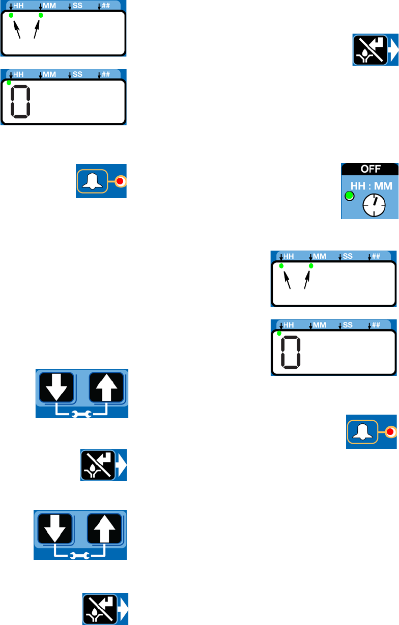
Enter the Time:
• The time displays in 24-Hour format. i.e., 2:45 PM
displays as 14:45.
• The clock is set in Hours and Minutes (HH:MM).
• The LED under the
HH lights when set-
ting hours and the
LED under the MM
lights when setting
minutes.
or
Max Model Setup
332305B 31
• The first programmable number of the HH (hour)
filed blinks, indicating the device is ready to program
the first digit of the hour.
• When programming a time of less then 12 hours,
you must program a leading zero in the first number
field and press the ENTER button to save the zero.
1. Use the UP and DOWN ARROW
buttons to move up and down
through the numbers 0-2 until the
desired number appears in the first
hour (HH) field.
2. Press the ENTER button to set the
number.
3. Use the UP and DOWN ARROW buttons to move
up and down through the numbers 0-9 until the
desired number for the second HH number field
appears.
4. Press the ENTER button to set the
number.
5. The next number field to the right blinks and the
LED under the MM lights indicating the G3 is ready
to program the minutes fields.
6. Repeat steps 1-4 to set the minutes (MM) fields.
7. After pressing the ENTER button to
set the time, the programmed Time
information is saved.
Programming ON Duration
• OFF, C1 (C2, C3) or
P1 (P2, P3) displays,
identifying the func-
tion you are program-
ming.
• Selection of OFF, C1 (C2, C3) or P1 (P2, P3) desig-
nates the way pump run time is controlled:
• C1, C2, C3 - Completing a specific number of
cycles measured by an external prox/cycle
switch
• P1, P2, P3 - Reaching a specific pressure
threshold measured by an external pressure
switch - OR,
• OFF - A specific duration of time elapses.
• The LED next to C/P1 lights, indicat-
ing which sensor of the pump control
you are programming using either a
specific number of cycles or by mon-
itoring a pressure switch.
• C / P2 and C / P3 controls functions to the second
and third sensors (when sensors are used).
• Only sensor inputs that are available on the unit can
be programmed.
NOTE: Field cannot be left blank. If C / P2 and C /
P3 are not used, OFF must be entered instead.
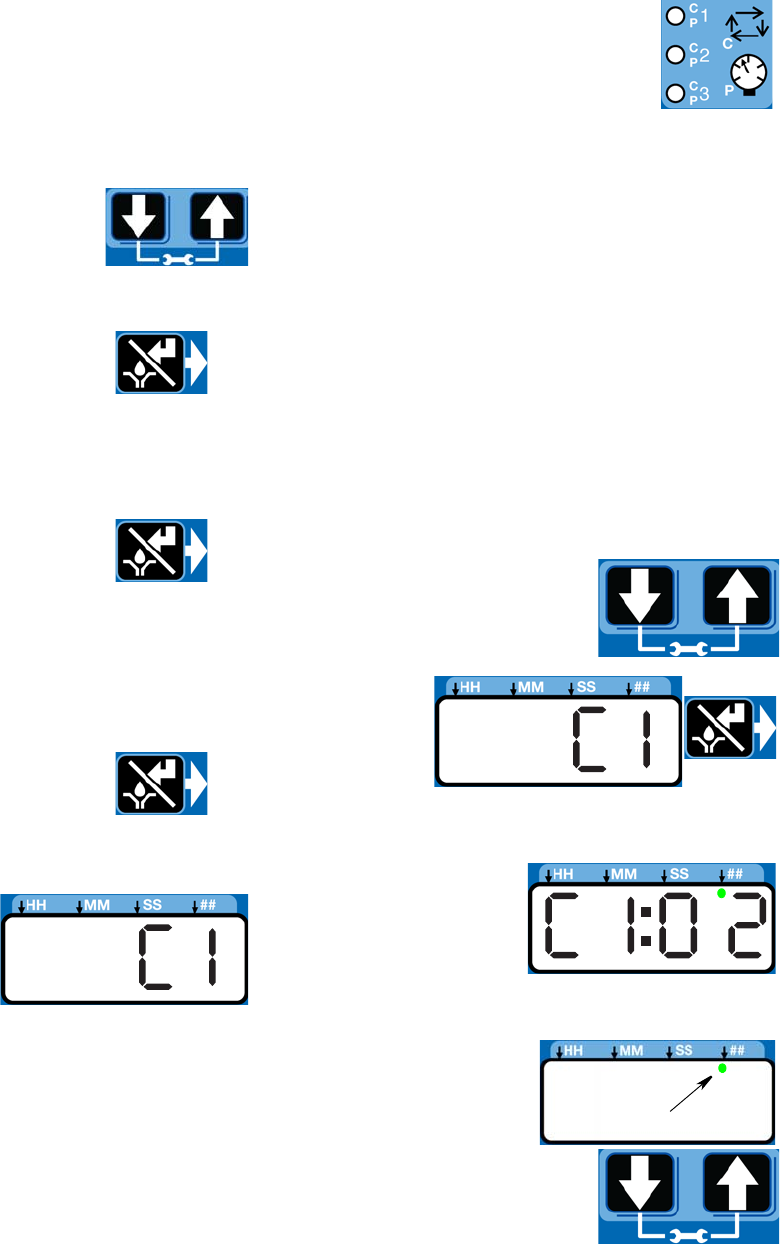
Cycle (C1, C2, C3) Setup
Cycle controls the number of lube cycles (as monitored
by an external cycle monitor) completed before the
pump rests.
NOTE:
• You must program at least one cycle. Zero is not an
available option.
1. Use UP or DOWN arrow but-
ton to toggle display between
OFF / C1 / P1 on the display.
2. When C1 is
on display,
press the
ENTER
button to
save selec-
tion and begin programming Cycle data.
• The first number
displayed after the
“C1” on the dis-
play blinks, indi-
cating the device
is ready to pro-
gram the number of C1 cycles.
• The LED under the
# sign lights when
setting the number
of cycles.
3. Program the number of
cycles by pressing the UP or
DOWN ARROW button to
move up or down through
number 0-9.
Max Model Setup
32 332305B
4. The cycle field is a 2 digit number.
When the correct first numeral of the
number displays, press the ENTER but-
ton to save the number. The cursor
automatically moves to the second number field.
NOTE: A leading zero (0) must be entered in the
first field if the number of cycles is fewer than 10.
5. Press the ENTER button, to save the C1
information.
• If your G3 is equipped with
more than one sensor input,
you will automatically be
prompted to begin selecting
the pump control type for the
next sensor. Repeat steps 1 - 5 to program cycles
for C2 and C3.
NOTE: If C / P2 and C / P3 are not used, the default
OFF setting must be entered instead.
6. After you set the last field and press the
ENTER button, the G3 saves the Cycle
information and moves to setting
Backup Time, page 34.
Pressure Control (P1, P2, P3) Setup
• For injector systems, monitoring pressure can be
used as a way to ensure sufficient pressure has
been reached to activate injectors. The pump runs,
building up enough pressure to cause injectors to
dispense fluid. Pressure continues to build to a pre-
set maximum, activating the (user supplier) pres-
sure switch. Then an external (user supplied) vent
valve opens and pressure reduces, priming the
injector for the next cycle.
• Pressure control is an ON / OFF selection only.
1. Use the UP or DOWN arrow
button to toggle between OFF
/ C1/ P1.
2. When P1
displays,
press
ENTER
button to
save
selection.
3. If your G3 comes equipped with more than one sen-
sor input, you will automatically be prompted to
begin selecting pump control type for the next sen-
sor. Repeat steps 1 - 2 to program P2 and P3.
If P1 / P2 / P3 is selected the vent valve time is
automatically set to 5 minutes. If the unit is used in
an injector based system and a sensor input is not
used, the user must update the vent valve time in
advanced programming. (See Advanced Program-
ming, A-3 Vent Valve Time, page 47.)
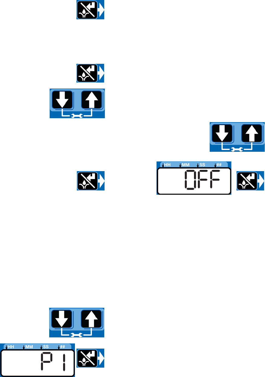
Input Not Used
Select OFF if your system does not use the applicable
input.
1. Use UP or DOWN arrow but-
ton to toggle between OFF /
C1 / P1 on the display.
2. When
OFF is on
the dis-
play,
press the
ENTER
button to save selection.
If the sensor inputs are available and none are used in
the ON Mode, the definition of the entered time is ON
TIME.
Examples:
Model G3-G-24MX-2LFL00-1DMVA2R3 has 4 sensors,
so C/P1, C/P2, and C/P3 and Machine Count can all be
programmed.
Model G3-G-24MX-2LFL00-10CV00R0 has 1 sensor,
only C/P1 is available for programming.
Backup Time
In both Cycle and Pressure Modes, a maximum run
Time (Backup Time) for the lubrication period must be
set up. If this Time expires before the lubrication is com-
pleted an alarm/warning is triggered and the pump
stops.
Max Model Setup
332305B 33
To determine the Backup Time, Graco recommends the
user verify the length of time it takes to complete a typi-
cal cycle and double that value (to a maximum of 30
minutes).
Backup Time is setup after Cycle or Pressure Sensor
Setup is complete.
NOTE:
• The LED next to the clock in the ON field lights, indi-
cating the Backup Time is being programmed.
• BACKUP (ON) Time is set as minutes and seconds
(MM:SS) only.
• The small flashing LED under the MM indicates you
are setting minutes.
• The first field (left side of display) blinks indicating
the device is ready for you to begin programming.
Programming Backup Time
NOTE: When programming a time of less than 10 min-
utes you must program the leading zero in the first num-
ber field and press the ENTER button to save the zero
selection.
1. To set the ON Time use the
UP or DOWN ARROW button
to scroll through numerals 0
to 5 until the desired number
appears in the first MM (min-
utes) field.
2. Press the ENTER button to lock in the
selection. The next MM number field to
the right flashes indicating it is ready for
programming.
3. Use the UP or DOWN
ARROW button to scroll
through numerals 0 to 9 until
the desired number appears
in the second MM number
field.
4. Press the ENTER button to lock in the
selection.
The next number field to the right
flashes and the LED lights under SS; indicating it is
ready to program the seconds fields.
5. Repeat steps 1 - 4 to set the SS (seconds) fields.
6. After pressing the ENTER button to set
the last SS field, all the programmed ON
Time information is saved.
The G3 automatically switches to the OFF Time
SETUP MODE.
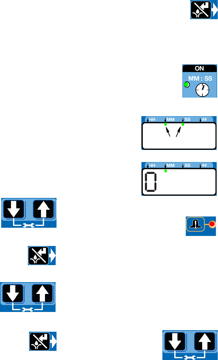
ON Time
• The LED next to the clock in the ON
field lights, indicating you are setting
the ON Time parameters.
• ON Time is set in Minutes and Seconds (MM: SS).
• An LED flashes under
either MM when pro-
gramming minutes
OR SS when pro-
gramming seconds.
• In SETUP MODE, the
number displayed in
the first field, on the
left side of display
blinks, indicating the
device is ready to pro-
gram the ON Time minutes.
• The total amount of ON Time cannot
exceed 30 minutes. If a value greater
than 30 minutes is entered, the RED
alarm LED lights and the value must
be updated.
If this time does not meet the application needs,
contact Graco Customer Support.
Programming ON Time
NOTE: When programming a time of less than 10 min-
utes you must program a leading zero in the first num-
ber field and press the ENTER button to save the zero
selection.
1. To set the ON Time use the
UP or DOWN ARROW button
to scroll through numerals 0
to 5 until the desired number
appears in the first MM (min-
utes) field.
OR
Max Model Setup
34 332305B
2. Press the ENTER button to lock in the
selection. The next MM number field to
the right flashes indicating it is ready for
programming.
3. Use the UP or DOWN
ARROW button to scroll
through numerals 0 to 9 until
the desired number appears
in the second MM number
field.
4. Press the ENTER button to lock in the
selection.
The next number field to the right
flashes and the LED lights under SS; indicating it is
ready to program the seconds fields.
5. Repeat steps 1 - 4 to set the SS (seconds) fields.
6. After pressing the ENTER button to set
the last SS field, all the programmed ON
Time information is saved.
The G3 automatically switches to the OFF Time
SETUP MODE.
PUMP OFF / REST Setup
After setting the parameters for either Cycle (C1, C2 or
C3) or Pressure (P1, P2, or P3) ON modes, the OFF or
pump rest cycle must be set up. There are 3 ways to
control this function:
• Machine Count switch activation, or
• Machine Count activations limited by a maxi-
mum Time, or
• A specific set amount of Time (similar to Time
Mode).
• If the machine count sensor input is available
and not used in the OFF Mode, the definition of
the entered time is OFF TIME.
Machine Count
1. After you set the last ON Time field
and press the ENTER button, the G3
automatically switches to the
Machine Count setup.
Notice the LED next to 123 on the G3 display lights
indicating you are now in the Machine Count setup
mode.
2. Press the UP or DOWN
ARROW button to move up
or down through number 0-9.
3. When the correct number displays,
press the ENTER button to set the num-
ber.
NOTE: If the machine count input is available on the unit
and not used, the value MUST be set to zero (0).
4. Repeat 2 - 3 to set the remaining fields.
NOTE: After the Machine Count value is entered, the
G3 can be programmed to backup the machine count
input with time.
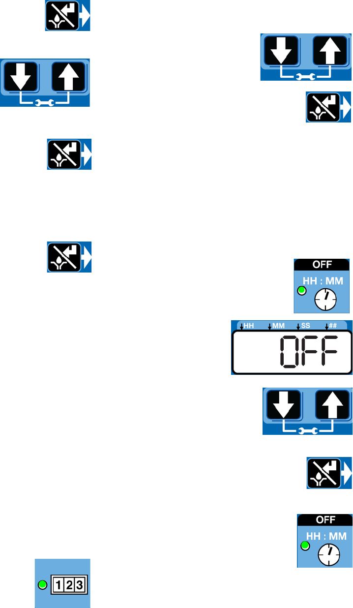
Backup Time Setup
1. The OFF Time LED lights.
OFF displays.
2. Press the UP or DOWN
ARROW button to change
OFF to ON on the display.
3. Press the ENTER button to set the
selection.
Backup Time
• The LED next to the clock in the OFF
field lights, indicating you are setting
the Backup Time parameters.
• OFF Time is set in Hours and Minutes
(HH: MM).
Max Model Setup
332305B 35
• An LED flashes under
either HH when pro-
gramming hours OR
MM when program-
ming minutes.
• In SETUP MODE the
number displayed in
the first field, on the
left side of display
blinks, indicating the
device is ready to pro-
gram the Backup Time hours.
• The total amount of Backup Time must
be at least twice as long as the pro-
grammed ON Time. If a value less
than twice the ON Time is entered, the
RED alarm LED lights and the value must be
updated.
If this time does not meet the application needs,
contact Graco Customer Support.
Programming Backup Time
NOTE: When programming a Backup Time of less than
10 hours you must program a leading zero in the first
number field and press the ENTER button to save the
zero selection.
1. To set the Backup Time use
the UP or DOWN ARROW
button to scroll through
numerals 0 to 9 until the
desired number appears in
the first HH (hour) field.
2. Press the ENTER button to lock in the
selection. The next HH number field to
the right flashes indicating it is ready for
programming.
3. Use the UP or DOWN
ARROW button to scroll
through numerals 0 to 9 until
the desired number appears
in the second HH number
field.
4. Press the ENTER button to lock in the
selection.
The next number field to the right
flashes and the LED lights under MM; indicating it is
ready to program the minutes fields.
5. Repeat steps 1 - 4 to set the next MM (minutes)
fields.
6. After pressing the ENTER button to set
the last MM field, the OFF Time informa-
tion is saved.
7. After selecting ON, refer to page 32.
NOTE: Backup time can be set in HH:MM for the
machine count input.
OFF Time
• The LED next to the clock in the OFF
field lights, indicating you are setting
the OFF Time parameters.
• OFF Time is set in Hours and Minutes
(HH: MM).
• An LED flashes under
either HH when pro-
gramming hours OR
MM when program-
ming minutes.
• In SETUP MODE the
number displayed in
the first field, on the
left side of display
blinks, indicating the
device is ready to pro-
gram the OFF Time hours.
• The total amount of OFF Time must be
at least twice as long as the pro-
grammed ON Time. If a value less
than twice the ON Time is entered, the
RED alarm LED lights and the value must be
updated.
If this time does not meet the application needs,
contact Graco Customer Support.
Programming OFF Time
NOTE: When programming a time of less than 10
hours you must program a leading zero in the first
number field and press the ENTER button to save the
zero selection.
OR
OR
Max Model Setup
36 332305B
1. To set the OFF Time use the
UP or DOWN ARROW button
to scroll through numerals 0
to 9 until the desired number
appears in the first HH (hour)
field.
2. Press the ENTER button to lock in the
selection. The next HH number field to
the right flashes indicating it is ready for
programming.
3. Use the UP or DOWN
ARROW button to scroll
through numerals 0 to 9 until
the desired number appears
in the second HH number
field.
4. Press the ENTER button to lock in the
selection.
The next number field to the right
flashes and the LED lights under MM; indicating it is
ready to program the minutes fields.
5. Repeat steps 1 - 4 to set the next MM (minutes)
fields.
6. After pressing the ENTER button to set
the last MM field, the OFF Time informa-
tion is saved.
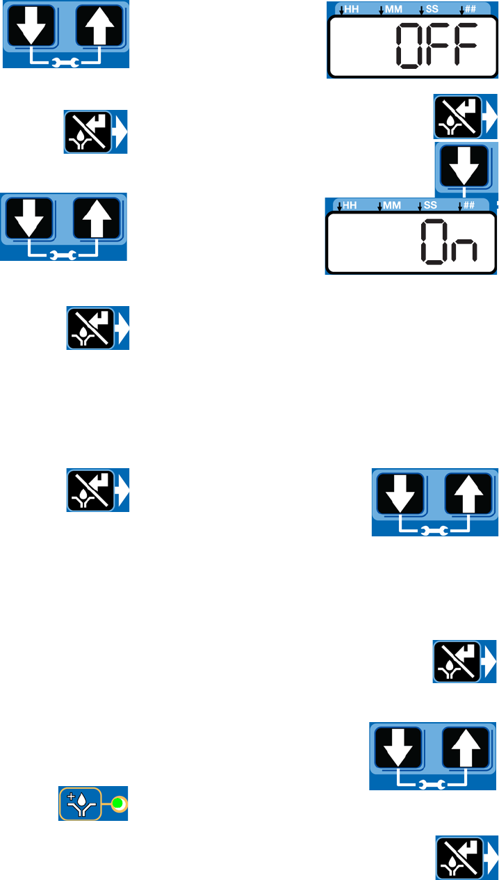
Prelube
The Prelube function determines operation of the pump
when power is applied. It can be set to OFF or ON.
OFF (default) - The unit resumes its lubrication cycle at
the point it was at when power was removed.
ON - The unit begins a pump cycle.
Setting Prelube
1. After you set the OFF Time information and press
the ENTER button, the G3 automatically switches to
the Prelube Delay setup.
Notice the LED next to the prelube
icon on the G3 display lights indicat-
ing you are now in the Prelube setup
mode.
2. OFF displays. If you
want the prelube
cycle to begin imme-
diately, leave this set
to OFF.
3. Press the ENTER button to set the
selection.
4. If you want to set a
prelube delay time,
press the DOWN
ARROW button to
change OFF to ON
on the display.
Prelube Delay
Prelube Delay can be entered to delay the start of the
pump’s cycle on power up. If prelube is set to ON, a pre-
lube delay time in MM:SS must be entered. By default,
the delay is set to 0 (begin an ON cycle immediately).
Delaying the prelube function may be desired if other
critical functions or systems of your machine or vehicle
are also coming on line during power up.
1. Prelube Delay is set in
MM:SS (minutes and sec-
onds). To set the time use the
UP or DOWN ARROW button
to scroll through numerals 0
to 5 until the desired number
appears in the first MM (minutes) field.
The maximum length of time Prelube Delay can be
set to is 59:59 (59 minutes:59 seconds).
2. Press the ENTER button to lock in the
selection. The next MM number field to
the right flashes indicating it is ready for
programming.
3. Use the UP or DOWN
ARROW button to scroll
through numerals 0 to 9 until
the desired number appears
in the second MM number
field.
4. Press the ENTER button to lock in the
selection.
The next number field to the right
Max Model Setup
332305B 37
flashes and the LED lights under SS; indicating it is
ready to program the seconds fields.
5. Repeat steps 1 - 4 to set the SS (seconds) fields.
6. After pressing the ENTER button to set
the last SS field the G3 automatically
switches to the RUN MODE.
DMS™ Models Only
Downloading Data
1. Plug the USB flash drive into the USB port.
NOTE: The G3 pump stops pumping as soon as the
USB flash drive is plugged into it.
2. The system automatically begins downloading data
to the USB drive.
3. “data” is displayed while the system
is downloading files.
4. When download is finished, “done” is
displayed.
5. G3 pump restarts cycle in the OFF mode.
6. Remove the USB flash drive.
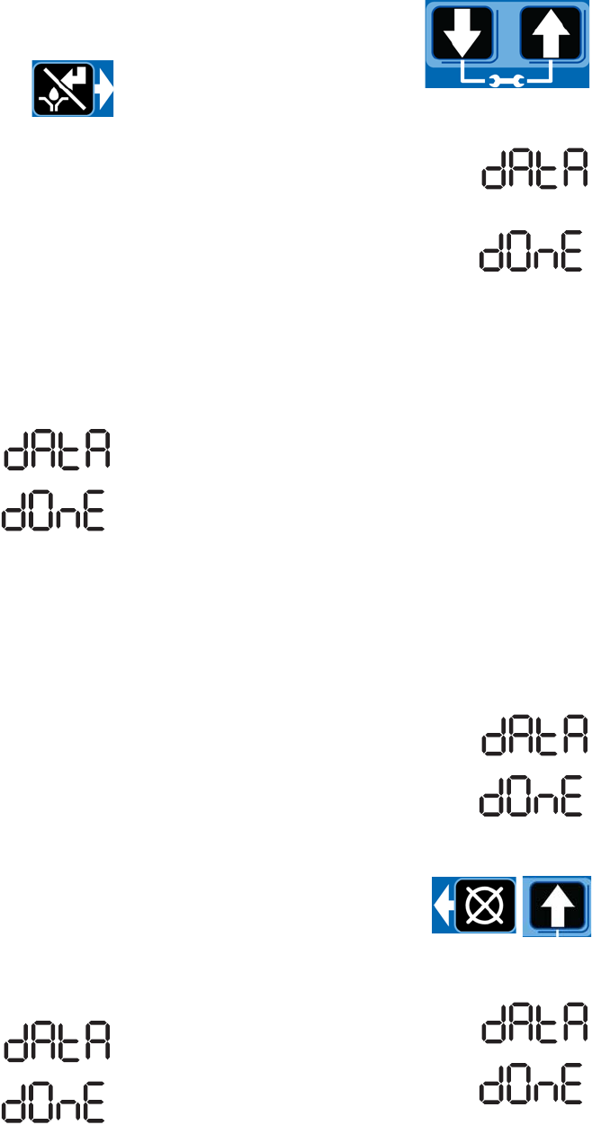
Storing Pump Program Settings
to the Flash Drive
The pump program settings file is named:
GRACO/G3Config/g3config.bin. This file cannot be
modified. Modification of the file or file name may cause
it to be unusable.
1. Plug the USB flash drive into the USB port.
NOTE: The G3 pump stops pumping as soon as the
USB flash drive is plugged into it.
2. The system automatically begins downloading data
to the USB drive.
3. “data” is displayed while the system
is downloading files.
4. When download is finished, “done” is
displayed.
5. G3 pump restarts cycle in the OFF mode.
6. After the download is com-
plete, press and hold the UP
and DOWN ARROW button
for 3 seconds to store the cur-
rent setup to the USB flash
drive.
7. “data” is displayed while the unit is
downloading and storing the configu-
ration on the USB drive.
8. When configuration is stored, “done”
is displayed.
9. G3 pump restarts cycle in the OFF mode.
10. Remove the USB flash drive.
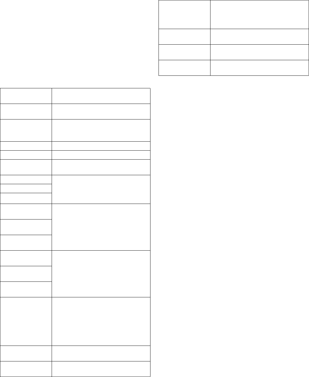
Uploading Pump Program
Settings to the Pump
1. Plug the USB flash drive into the USB port.
NOTE:
• The USB flash drive must contain file
GRACO/G3Config/g3config.bin.
• The G3 pump stops pumping as soon as the
USB flash drive is plugged into it.
2. The system automatically begins downloading data
to the USB drive.
3. “data” is displayed while the system
is downloading files.
4. When download is finished, “done” is
displayed.
5. G3 pump restarts cycle in the OFF mode.
6. After the download is com-
plete, press and hold the
RESET button and UP
ARROW button for 3 seconds
to upload the setup stored in the USB flash drive.
7. “data” is displayed while the unit is
uploading the configuration data.
8. When upload is finished, “done” is
displayed.

Max Model Setup
38 332305B
9. G3 pump restarts cycle in the OFF mode.
10. Remove the USB flash drive.
11. After the USB flash drive is
removed, press and hold the
UP and DOWN ARROW but-
tons for 3 seconds to enter
the SETUP MODE (see
Entering Setup Mode, page 29).
12. In SETUP MODE, set the YEAR, MONTH, DATE
and TIME (see Setting the Real Time Clock, page
30).
13. After pressing the ENTER button to set
the TIME, press the RESET button to
exit the SETUP MODE.
Viewing the UNIT DMS ID Number
1. In RUN mode, press and hold the
DOWN ARROW button.
2. The Unit DMS ID number displays. The
unit continues to normal operation while
the DMS ID is displayed.
3. Release the DOWN ARROW button after viewing
the DMS ID number.

Operation / Data Log
332305B 39
Operation / Data Log
During operation the G3 Pump stores information as
Log and Summary Files.
Logs contain the following information:
• Log Name
• DMS ID Number
• Current Software Graco Part Number
• Current Software Version
• Date and Time of Upload
System Event Log
The System Event Log lists the date and time of the last
800 common system events such as pump cycles, man-
ual run and setting changes. The most recent event is
listed first.
The log file is stored in a folder structure created by the
pump DMS ID and download date. If multiple downloads
are done on the same date, the existing files will be writ-
ten over.
The folder structure is as follows:
GRACO/G3_{DMS_id}/{download date - YYYYm-
mDD}/EVENTLOG.CSV
Example: GRACO/G3_00025/20100911/EVENT-
LOG.CSV.
Sample System Event Log
Example Event Log 1: Pump cycle of a divider valve
system with a proximity switch set to detect 5 divider
valve cycles.
G3 System Event Log
DMS ID Number: 0025 (see page 38)
Software Part Number: 16F821
Software Version: 1019
09/29/2010 14:1400
Date Time Description
9/29/2010 14:13:02 Pump Run Off
9/29/2010 14:13:02 C1 Cycle Completed
9/29/2010 14:12:39 C1 Cycle Detected
9/29/2010 14:12:34 C1 Cycle Detected
9/29/2010 14:12:28 C1 Cycle Detected
9/29/2010 14:12:23 C1 Cycle Detected
9/29/2010 14:12:17 Pump Run On
Operation / Data Log
40 332305B
Example Event Log 2: Pump cycle of an injector valve
system with a pressure switch feedback.
Common System Events are listed below.
Error Log
The Error Log lists Set Time and Clear Time for the last
400 faults and warnings. The most recent event is listed
first.
The log file is stored as:
GRACO/G3_{DMS_id}/{download date - YYYYm-
mDD}/ERRORLOG.CSV
Example: GRACO/G3_00025/20100911/ERROR-
LOG.CSV.
Sample Error Log
Date Time Description
9/29/2010 13:28:12 Venting Completed
9/29/2010 13:23:12 Venting Detected
9/29/2010 13:23:11 Pump Run Off
9/29/2010 13:23:11 P1 Pressure Completed
9/29/2010 13:22:20 Pump Run On
Pump Run On The pump entered an on cycle and is
operating and dispensing material.
Pump Run Off The pump entered an off cycle and is
not dispensing.
Pump Run Can-
celled
A pump on cycle was cancelled by
pressing the cancel button on the front
panel and holding it for 3 seconds.
G3 Power On The pump powered on.
G3 Power Off The pump powered off.
Program Variable
Change
The setup mode was entered.
C1 Cycle Detected The system is set up to monitor a prox-
imity switch on a divider valve using the
sensor input (C1, C2, and/or C3) and
has detected one divider valve cycle.
C2 Cycle Detected
C3 Cycle Detected
C1 Cycle Com-
pleted
The system is set up to monitor a prox-
imity switch on a divider valve using the
sensor input (C1, C2, and/or C3) and
has achieved the number of counts
required by the system for that input,
completing a pump on cycle.
C2 Cycle Com-
pleted
C3 Cycle Com-
pleted
P1 Pressure Com-
pleted
The system is set up to monitor a pres-
sure switch for an injector system using
sensor input (P1, P2, and/or P3), the
system has achieved pressure and the
switch has activated, completing a
pump on cycle.
P2 Pressure Com-
pleted
P3 Pressure Com-
pleted
Machine Count
Completed
The system is set up to monitor a sen-
sor on the equipment being lubricated
using the machine count input and has
achieved the number of counts required
by the system for that input, completing
a pump off cycle and initiating a pump
on cycle.
Local Manual Run
Initiated
The manual run button was pressed,
initiating a pump on cycle.
Remote Manual
Run Initiated
The remote manual run button was
pressed initiating a pump on cycle.
Venting Detected In an injector system, the pump on cycle
has completed and the system is cur-
rently venting pressure through the vent
valve.
Prelube Initiated The pump has entered a prelube delay
after powering up.
Prelube Completed The pump has completed prelube delay
and will begin a pump on cycle.
Successful Pin
Code Entry
The pin code was successfully entered
and the user has entered setup mode.
G3 Error Log
DMS ID Number: 00025 (see page 38)
Software Part Number:16F821
Software Version:0205
12/31/2015 23:04:00
Date Time Description
12/31/2015 23:03:54 Low Level Cleared
12/31/2015 23:03:42 Low Level Fault
12/31/2015 23:03:32 Low Level Warning
12/31/2015 23:03:22 P2 Not Detected Cleared
12/31/2015 23:03:22 C1 Not Detected Cleared
12/31/2015 23:03:19 P2 Not Detected
12/31/2015 23:03:19 C1 Not Detected
12/31/2015 23:02:20 Machine Count Not Detected
12/31/2015 23:02:11 Machine Count Not Detected

Operation / Data Log
332305B 41
Common Error Log entries are listed below.
Software Fault An internal software error
occurred. Contact Graco Cus-
tomer Service.
Low Level Warning The unit entered a low level
warning mode and is running
low on material. The pump
continues to dispense material
for the duration of the low level
alarm time specified by the
unit.
Low Level Fault The alarm time in low level
warning has elapsed. The unit
will not pump until the reservoir
is filled and the fault is cleared.
Cycle 1 Not Detected In a divider valve system, the
system has not received the
programmed number of divider
valve cycles for the specified
input in the programmed
backup time.
Cycle 2 Not Detected
Cycle 3 Not Detected
Pressure 1 Not
Detected
In an injector system the sys-
tem has not received a signal
from the pressure switch in the
designated backup time.
Pressure 2 Not
Detected
Pressure 3 Not
Detected
System Already Pres-
surized 1
In an injector system the pres-
sure switch is activated when
the unit enters a pump on
mode and may not have
vented properly.
System Already Pres-
surized 2
System Already Pres-
surized 3
Machine Count Sensor
Failure
The specified number of
machine count input activa-
tions was not received within
the designated backup time.
Motor Overcurrent The unit is out of expected
motor current range. Check the
system to determine that it is
functioning correctly (i.e., no
blocked lines). Continued oper-
ation at excessive motor cur-
rents will cause degradation in
pump life.
High Temperature
Warning
Internal temperature of the unit
is above the designated oper-
ating. Check the unit and sys-
tem to determine that it is
functioning correctly. Operating
outside of the specified tem-
perature range may cause
reduced performance and pos-
sible unit failure.
Low Temperature
Warning
Internal temperature of the unit
is below the designated operat-
ing. Check the unit and system
to determine that it is function-
ing correctly. Operating outside
of the specified temperature
may cause reduced perfor-
mance and possible unit fail-
ure.
USB Unable to Mount The USB flash drive that was
installed was unable to connect
and communicate with the
pump.
USB Unsupported
Device
The USB flash drive is unsup-
ported. Use a different flash
drive.
USB File Not Found The pump program setting file
was not found or created cor-
rectly. Restore the setting file
to the flash drive.
USB Folder Navigation The pump program setting file
was not found or created cor-
rectly. Restore the setting file
to the flash drive.
USB Invalid File The pump program settings file
was not found or created cor-
rectly. Restore the setting file
to the flash drive.
Failed Pin Code Entry A failed attempt was made to
enter the pin code password.
Operation / Data Log
42 332305B
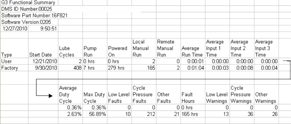
Functional Summary
The Functional Summary contains two types of data.
• The first report type, labeled User under the Type
heading in the first column of the Sample Functional
Summary, only provides data compiled since the
last time the Functional Summary was reset through
present day (see A6 - Clearing the Functional and
Technical User Summary, page 49).
This is very similar to the resettable trip odometer in
your car.
• The second report type, labeled Factory under the
Type heading in the first column of the Sample
Functional Summary, covers the cumulative life of
the pump from the first day it was put into service
through present day.
This is very similar to an odometer in your car.
The log file is stored as:
GRACO/G3_{DMS_id}/{download date - YYYYm-
mDD}/FUNCSUM.CSV
Example: GRACO/G3_00025/20100911/FUNC-
SUM.CSV
Sample Functional Summary
(see page 38)

Operation / Data Log
332305B 43
Common Functional Summary Data entries are listed
below.
Number of Cycles The number of lubrication cycles
the unit has started.
Total Run Hours Total amount of hours the pump
has been in the ON mode of the
ON/OFF cycle.
Total Powered On Hours Total number of hours that the
unit has been powered on.
Local Manual Run The number of times the manual
run button was pressed.
Remote Manual Run The number of times the remote
manual run button was pressed.
Average Run Time The average amount of time per
lubrication cycle that the pump
has been running (MM:SS).
Average Cycle 1 Time The average amount of time the
unit has been operating before
the specified feedback for the
sensor input was received (prox-
imity switch counts in divider
valve systems and pressure
switch activation in injector sys-
tems).
Average Cycle 2 Time
Average Cycle 3 Time
Average Duty Cycle The average percentage of time
the unit has been pumping while
it has been powered on.
Max Duty Cycle The highest percentage of time
for one lubrication cycle that the
unit has been pumping while it
has been powered on.
Total Low Level Faults Total number of low level faults.
Total Cycle Pressure
Faults
Total number of faults related to
sensor feedback in an injector or
divider valve system.
Total Other Faults Faults other than low level or
sensor feedback.
Total Fault Hours Number of hours the system has
been powered on in fault mode.
Total Low Level Warnings Number of low level warning
conditions.
Total Cycle Pressure
Warnings
Total number of warning condi-
tions related to sensor feedback.
This is only applicable if fault
retries are used.
Total Other Warnings All other warnings including tem-
perature and motor current.
Operation / Data Log
44 332305B
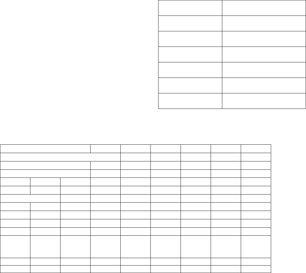
Technical Summary
The Technical Summary contains two types of data.
• The first report only provides data compiled since
the Pump Summary was reset to present day (see
A6 - Clearing the Functional and Technical User
Summary).
This is very similar to the resettable trip odometer in
your car.
• The second is a report that covers the cumulative
life of the pump from the first day it was put into ser-
vice to present day.
This is very similar to an odometer in your car.
The log file is stored as:
GRACO/G3_{DMS_id}/{download date - YYYYm-
mDD}/TECHSUM.CSV
Example: GRACO/G3_00025/20100911/TECH-
SUM.CSV
Common Technical Summary Data entries are listed
below.
Sample Technical Summary
Average Input Board
Voltage (DC)
The average input voltage mea-
sured by the internal circuit board.
Peak Input Board Volt-
age (DC)
The peak input voltage measured
by the internal circuit board.
Average Motor Current The average motor current mea-
sured by the unit.
Peak Motor Current The peak motor current mea-
sured by the unit.
Average Internal Tem-
perature
The average internal tempera-
ture seen by the unit.
Peak Internal Tempera-
ture
The peak internal temperature
seen by the unit.
Low Internal Tempera-
ture
The lowest internal temperature
seen by the unit.
G3 Technical Summary
DMS ID Number: 00025 (see page 38)
Software Part Number:16F821
Software Version: 0205
12/27/2010 9:50:51
Latest Values
Temp Voltage
31C 23.877
Type Start Date Average
Board
Voltage
Peak
Board
Voltage
Average
Motor
Current
Peak
Motor
Current
Average
Internal
Temp
Peak
Internal
Temp
Low
Internal
Temp
User 12/21/2010 23.877 23.877 0.062 0.06230C 35C 28C
Factory 9/30/2010 22.804 23.877 1.091 0.36233C 42C -10C

Advanced Programming
332305B 45
Advanced Programming
There are 7 Advanced Programming options. The following Table Identifies each option and when it is used.
Advanced
Option Model Setting Format/ Description Why Use This?
A1 Max Lockout
Code
(Optional)
Secures setup modes with
PIN
Prevents unauthorized users to adjusting
settings.
A2 Max Low Level
Alarm Time
MM:SS (minutes:seconds)
sets amount of time
between Low Level Warning
to Low Level Fault.
Default = 3 minutes
To accommodate most lubrication situa-
tions, a conservative amount of time is pro-
grammed between the low level warning
and fault to help protect unit from running
dry. If necessary the amount of time the
unit runs before stopping due to a low level
fault can be adjusted.
A3 Max Vent Valve
Time
MM:SS (minutes:seconds)
sets amount of time vent
valve stays open after Pump
ON Mode.
Default = 5 minutes
• In an injector based system that does not
use a sensor for feedback, determines
the amount of time the system vents.
• Vent time can be modified.
A4 Max Alarm Retry Sets number of automatic
retries after a Cycle or Pres-
sure Alarm.
Default = 0
Establishes the number of times the unit
automatically retries lubricating after a
cycle or pressure alarm to determine if a
temporary or false signal can be cleared.
A5 Max Active
Alarm
Changes alarm output
behavior.
Default = OFF
Uses alarm output to determine if a unit has
an alarm AND/OR loses power.
The output turns ON when power is
applied. It turns OFF when power is lost or
an alarm occurs.
Normal operation (OFF) will only activate
alarm output in an alarm condition when
power is on.
Can change (set to ON) to activate alarm
with power ON and deactivate with power
OFF OR warning.
Used to manage power outage.
A6 DMS™
Equipped
Models
Functional
and Techni-
cal User
Summary
Reset
Clears the Functional and
Technical User Summaries
Allows user to track lube events from a spe-
cific point (reset), i.e. a month to month
evaluation.
A7 Max Constant
Alarm Out-
put on Fault
Changes alarm output
behavior.
Default = OFF
This function changes the behavior of the
alarm output in a fault from either toggling
once every second or steady on.
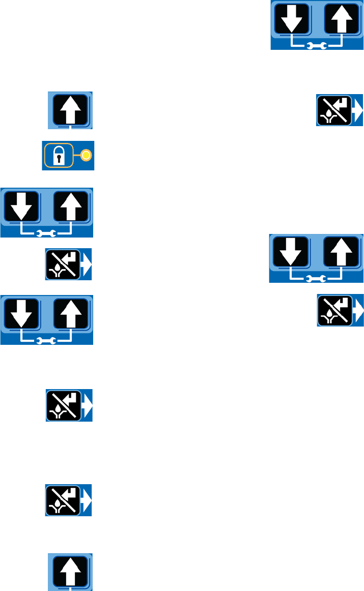
Advanced Programming
46 332305B
Entering a PIN Code for the First Time
A1 - Setting Up PIN Code
A PIN Code can be programmed into the G3 to protect
the settings from inadvertently being changed by unau-
thorized users.
1. Press the UP ARROW button for 10
seconds.
The LED next to the LOCK ICON on the
display lights, indicating you have entered
the PIN Mode.
2. The word OFF appears in the
display. Press the UP or
DOWN ARROW button to
change this to ON.
3. Press the ENTER button to enter the
PIN Code.
4. The cursor automatically is
positioned to entered the first
character of the PIN Code.
Use the UP and DOWN
ARROW buttons to move up
and down through the numbers 0-9 until the first
number in the PIN code is displayed in the field.
5. Press the ENTER button to set the
number. The cursor automatically
moves to the next number field.
6. Repeat steps 4 and 5 for each PIN Code prompt
field.
7. Press the ENTER button to save the
PIN Code and exit Advanced Setup.
Entering Advanced Setup
Press the UP ARROW button for 10 sec-
onds.
If the G3 was previously set up to require a
PIN Code, the LED next to the LOCK ICON lights, indi-
cating a PIN Code is required.
1. The cursor is automatically
positioned to enter the first
character of the PIN Code.
Use the UP and DOWN
ARROW buttons to move up
and down through the numbers 0-9 until the first
number in the PIN code is displayed in the field.
2. Press the ENTER button to set the num-
ber. The cursor automatically moves to
the next number field.
3. Repeat steps 1 and 2 for each PIN Code prompt
field.
If the PIN Code you entered is correct, the first editable
character on the display will flash.
Selecting Advanced Setup Options
1. Press the UP or DOWN
ARROW button to move up
or down through Advanced
Options A1 - A7.
2. Press the ENTER button to set the
selection.
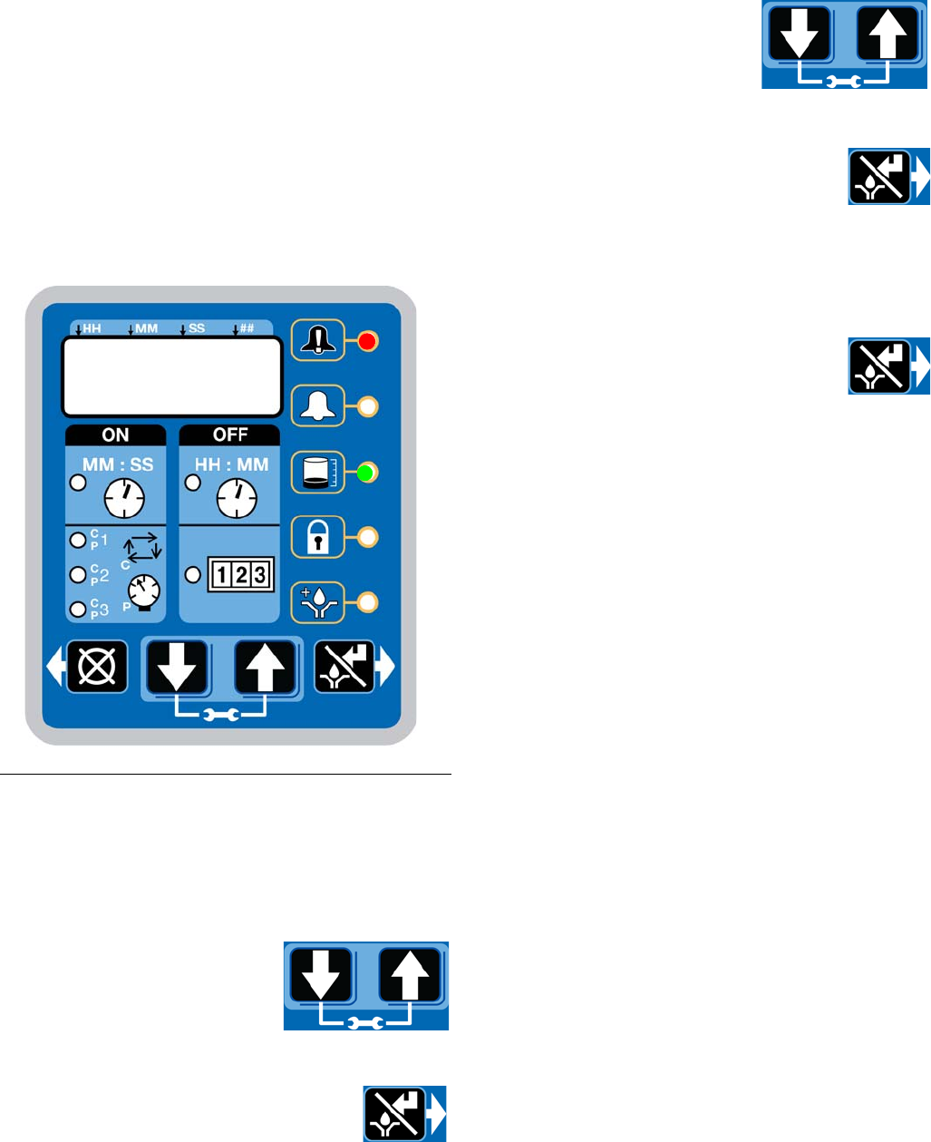
Advanced Programming
332305B 47
A2 - Low Level Alarm Time
Pump ON mode only.
Programs the amount of time in MM: SS (minutes and
seconds) the pump can run between a Low Level Warn-
ing and a Low Level Fault to help protect unit from run-
ning dry.
The maximum recommended length of time is 3:00 min-
utes.
Fault, and Low Level LED illuminate. (Max Model Dis-
play shown in illustration below).
NOTE: When programming a time of less than 10 min-
utes you must program a leading zero in the first num-
ber field and press the ENTER button to save the zero
selection.
1. To set the time use the UP or
DOWN ARROW button to
scroll through numerals 0 to 9
until the desired number
appears in the first MM (min-
utes) field.
2. Press the ENTER button to lock in the
selection. The next MM number field to
the right flashes indicating it is ready for
programming.
3. Use the UP or DOWN
ARROW button to scroll
through numerals 0 to 9 until
the desired number appears
in the second MM number
field.
4. Press the ENTER button to lock in the
selection.
The next number field to the right
flashes and the LED lights under SS; indicating it is
ready to program the seconds fields.
5. Repeat steps 1 - 4 to set the SS (seconds) fields.
6. After pressing the ENTER button to set
the last SS field, all the programmed ON
Time information is saved.
Unit exits Advanced Programming.
A3 - Vent Valve Time
The Vent Valve Time is the amount of time the vent
valve stays open after a cycle is completed.
The recommended Vent Valve Time is 5 minutes.
To bypass the Vent Valve Time enter a value of 00:00.
Vent Valve time must be less than the programmed OFF
time (page 35). If it is not set to a value less than the
programmed OFF time, the G3 will automatically adjust
the time to a value 2 seconds less than the set OFF
time.
FIG. 23
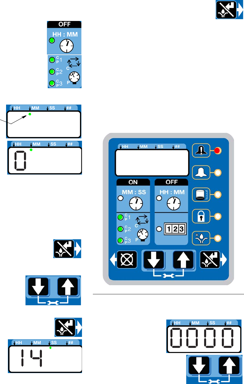
Advanced Programming
48 332305B
To set Vent Valve Time:
NOTE:
• The LED next to the clock in the OFF
field lights and P1, P2, and P3, indi-
cating the Vent Valve Time is being
programmed.
• Time is set as minutes and seconds (MM:SS) only.
• The small flashing
LED under the MM
indicates you are
setting Minutes.
• The first field (left
side of display) blinks
indicating the device
is ready for you to
begin programming.
• When programming a time of less then 10 minutes
you must program a leading zero in the first number
field and press the ENTER button to save the zero
selection.
1. To set the Time use the UP or DOWN ARROW but-
ton to scroll through numerals 0 to 5 until the
desired number appears in the first minute field.
2. Press the ENTER button to lock in the
selection. The next minute field to the
right flashes indicating it is ready for
programming.
3. Use the UP or DOWN
ARROW button to scroll
through numerals 0 to 9 until
the desired number appears
in the second minute field.
4. Press the ENTER button to lock in the
selection.
5. The next number field
to the right flashes
and the LED lights
under SS; indicating
it is ready to program
the Seconds fields.
6. Repeat steps 1 - 4 to set the MM (seconds) fields.
7. After pressing the ENTER button to set
the last seconds field, all the pro-
grammed Time information is saved.
Unit exits Advanced Programming.
A-4 Alarm Retry
Programs the number of times G3 will automatically
retry running a lubrication cycle after a cycle or pressure
alarm activates. The default setting is 0. For assistance
determining a reasonable number of Alarm Retries to
program for your application, contact Graco Customer
Service or your local Graco distributor.
1, 2, and 3 and Fault LED’s illuminate.
To set the Alarm Retry:
1. The default value
0000 appears in the
display.
2. Press the UP or DOWN
ARROW button to move up
or down through number 0-9.
FIG. 24
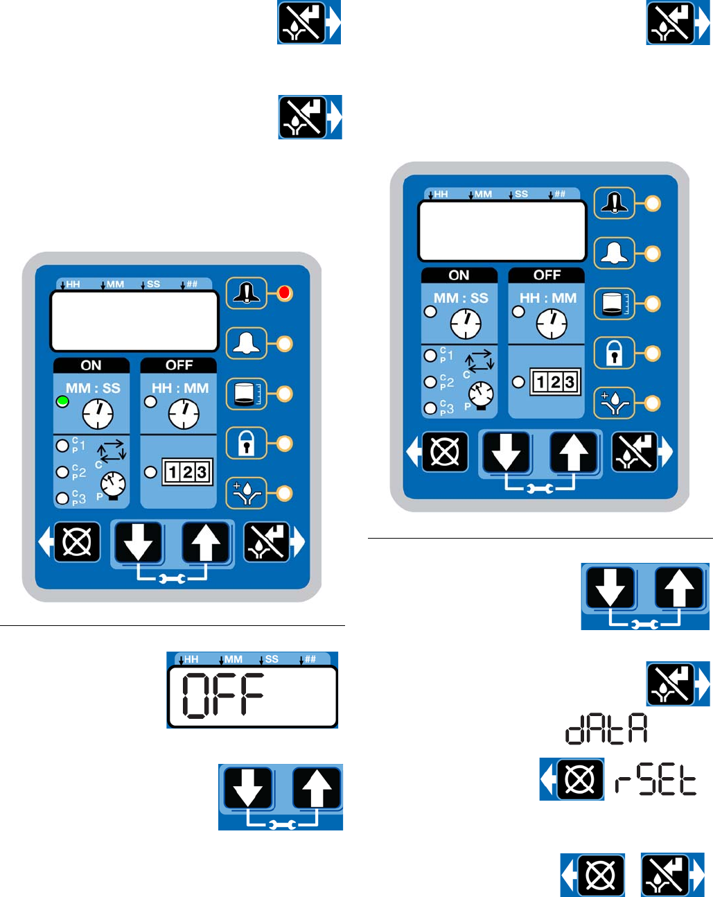
Advanced Programming
332305B 49
3. When the correct number displays,
press the ENTER button to set the num-
ber.
4. Repeat 2 - 3 to set the remaining fields.
5. Press the ENTER button to exit
Advanced Programming.
A-5 Active Alarm
Changes the alarm output behavior. Uses output to
determine if a fault has occurred.
Fault and ON LED’s illuminate.
1. The default OFF dis-
plays.
2. Press the UP or DOWN
ARROW button to change
OFF to ON on the display to
activate alarm condition.
3. Press the ENTER button to exit
Advanced Programming.
A6 - Clearing the Functional and Technical
User Summary (DMS™ Models only)
The Pump Summary shows run details since the last
time the summary was cleared.
1. Press the UP or DOWN
ARROW button to move
through Advanced Options
until Advanced Option A6 is
displayed.
2. Press the ENTER button.
3. “Data” displays.
4. Press the RESET but-
ton. “Reset” displays.
The summary data is
cleared.
5. Press the RESET or
ENTER button to exit.
FIG. 25
FIG. 26
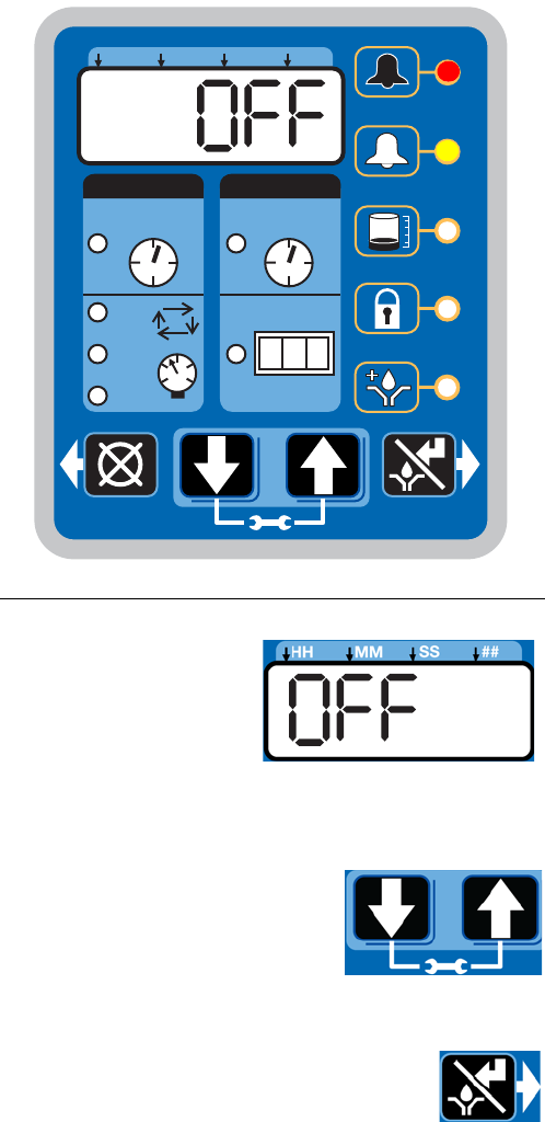
Advanced Programming
50 332305B
A-7- Constant Alarm Output on Fault
This function changes the behavior of the alarm output
in a fault from either toggling once every second
(default) or steady on.
Fault and Warning LEDs Illuminate
1. The default OFF is
displayed. The alarm
output will toggle
once a second.
2. Press the UP or DOWN
ARROW to change OFF to
ON on the display to change
the alarm output to be on
steady
3. Press the ENTER button to exit
Advanced Programming.
FIG. 27
ON OFF
!
123
HH MM SS ##
MM : SS HH : MM
2
3
1
P
C
C
P
C
P
C
P
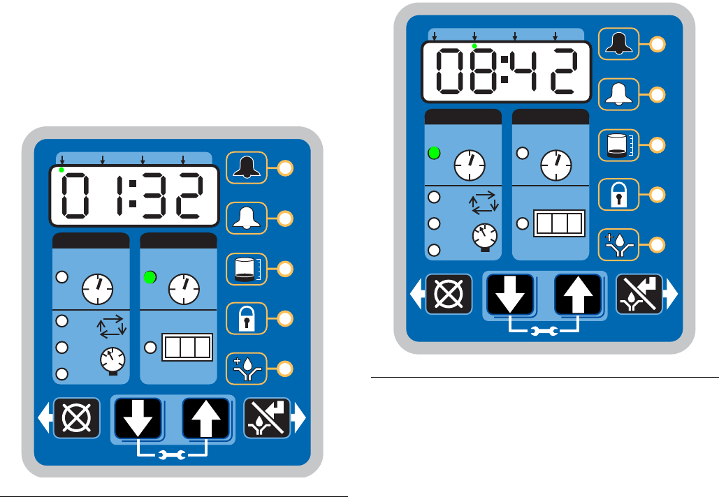
Run Mode
332305B 51
Run Mode
Time Control
After setup is complete, the G3 automatically begins to
run the OFF Time sequence (FIG. 28).
• The G3 runs the programmed OFF sequence.
(Notice the OFF Time LED on the display lights and
the OFF Time counts down on the display.)
• The example shown in FIG. 28 shows an OFF Time
of 1 hour and 32 minutes before the lubrication
cycle begins.
• When the OFF Time count reaches zero, the G3
Automatic Lubrication Pump turns the pump on and
it runs for the programmed ON Time cycle (FIG. 29).
(Notice the ON Time LED is now illuminated on the
display.)
• The example shown in FIG. 29 shows an ON Time
of 8 minutes and 42 seconds before the lubrication
cycle ends.
• When the ON Time count reaches zero, the pump
shuts off again and the system again runs OFF
Time cycle and the OFF Time LED is now again illu-
minated (FIG. 28).
This sequence repeats itself until the device is
reprogrammed or an alarm occurs.
• If power to the pump is lost during a lubrication
cycle, when power is restored the pump will resume
the cycle with the same amount of time remaining in
the cycle as when the power was lost.
FIG. 28
ON OFF
!
123
HH MM SS ##
MM : SS HH : MM
2
3
1
P
C
C
P
C
P
C
P
FIG. 29
ON OFF
!
123
HH MM SS ##
MM : SS HH : MM
2
3
1
P
C
C
P
C
P
C
P
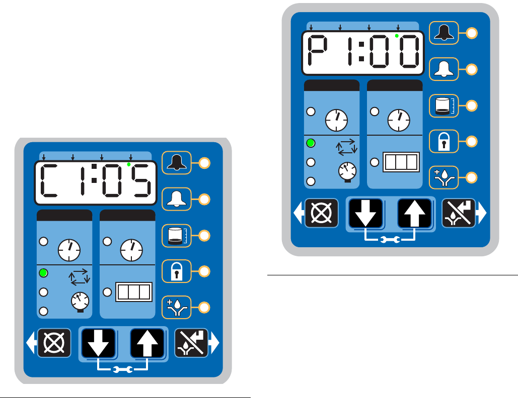
Run Mode
52 332305B
Lubrication Mode (Pump ON) Controls
In Max models the Lubrication Mode (Pump ON) can be
controlled by either cycle and/or pressure sensors.
If cycle and/or pressure controls have been set to some-
thing other than OFF the display will alternate between
cycles (C1, C2, C3) and/or active sensors (P1, P2, P3)
and Backup Time.
If cycle or pressure controls have been set to OFF then
the Lubrication Mode (Pump ON) will be controlled by
On Time (see Time Control, page 51).
With cycle and/or pressure controls set, the lubrication
cycle (Pump ON) is ended by meeting all required cycle
and/or pressure settings.
Cycle Control
• A set number of triggered counts in a cycle
based system (C1). Typically a proximity switch
connected to a divider valve.
• The LED next to the appropriate sensor (C/P1,
C/P2, C/P3) illuminates.
• The display indicates the sensor (C1, C2, C3)
and the remaining cycles for that sensor (FIG.
30).
The example shown in FIG. 30 shows sensor C1
with 5 cycles remaining.
Pressure Control
• A single triggered count in a pressure based
system (P1). Typically a pressure switch on the
end of a line of injectors.
• The LED next to the appropriate sensor (C/P1,
C/P2, C/P3) illuminates (FIG. 31 and FIG. 32).
• The display indicates the sensor (P1, P2, P3)
and whether the pressure switch for that sensor
has been triggered or not.
- 01 = pressure switch has not been triggered
- 00 = pressure switch is triggered.
The example shown in FIG. 31 shows sensor P1
with a pressure switch that has been triggered.
FIG. 32 (page 53) shows sensor P2 with a pres-
sure switch that has NOT been triggered.
FIG. 30
ON OFF
!
123
HH MM SS ##
MM : SS HH : MM
2
3
1
P
C
C
P
C
P
C
P
FIG. 31
ON OFF
!
123
HH MM SS ##
MM : SS HH : MM
2
3
1
P
C
C
P
C
P
C
P
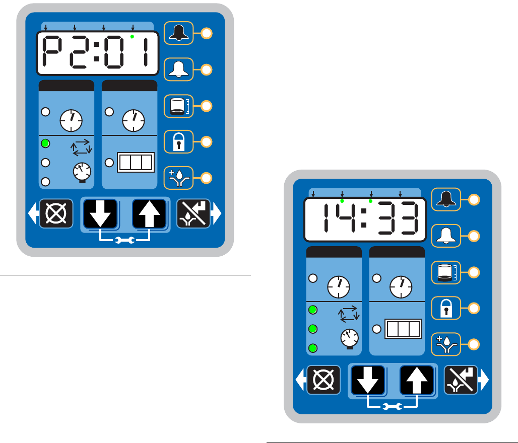
Run Mode
332305B 53
Backup Time
• In both Cycle and Pressure modes a Backup
Time (maximum run time) has been set.
• The LED(s) next to all programmed sensors
(C/P1, C/P2, C/P3) illuminate.
• The display shows time remaining until a fault.
The example shown in FIG. 33 shows 14 min-
utes and 33 seconds left until the fault occurs.
• If all cycle and/or pressure requirements are
met the unit exits the lubrication cycle (Pump
ON) and enter the rest cycle (Pump OFF).
Rest Mode (Pump OFF) Controls
In Max models the Rest Mode (Pump OFF) is controlled
by machine counts.
If the Machine Count is set to a value greater than 0000
and the Backup Time option is activated, the display
will alternate between Machine Counts and Backup
Time.
If Machine Count has been set to a value greater than
0000 and the Backup Time option is NOT activated, the
display will only show the number of Machines Counts
remaining.
FIG. 32
ON OFF
!
123
HH MM SS ##
MM : SS HH : MM
2
3
1
P
C
C
P
C
P
C
P
FIG. 33
ON OFF
!
123
HH MM SS ##
MM : SS HH : MM
2
3
1
P
C
C
P
C
P
C
P
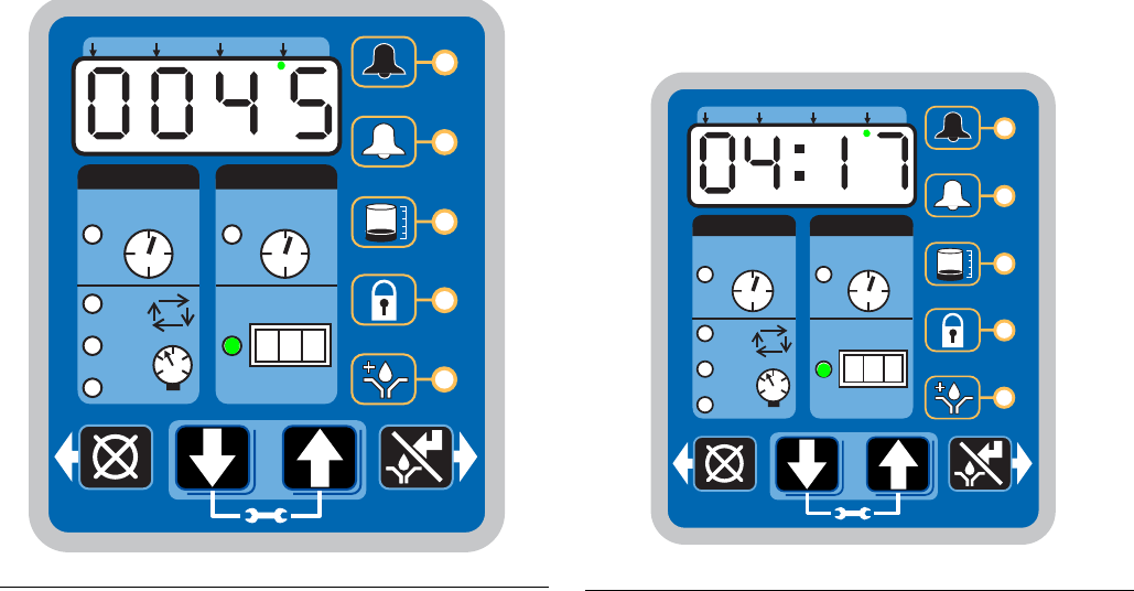
Run Mode
54 332305B
With machine count set, the Rest Cycle (Pump OFF) is
ended when the machine count reaches zero (0000).
Machine Count
• A set number of triggered counts.
• The LED next to 1-2-3 illuminates (FIG. 34).
• The display indicates the number of machine
counts remaining.
The example shown in FIG. 34 shows the
remaining number of machine counts is 0045.
Backup Time
In Machine Count mode, if a Backup Time (maximum
rest time) has been set:
• The LED next to 1-2-3 illuminates (FIG. 35).
• The display shows the amount of time remain-
ing till a fault.
The example shown in FIG. 35 shows 4 hours
and 17 minutes remaining until a fault occurs.
• If the Machine Count requirements are met the
unit will exit the Rest Mode (Pump OFF) and
enter the Lubrication Mode (Pump ON).
OFF Time
In Max models if the Machine Count is set to 0000 then
Reset Mode (Pump OFF) is controlled with OFF Time
(see Time Control, page 51).
FIG. 34
ON OFF
!
123
HH MM SS ##
MM : SS HH : MM
2
3
1
P
C
C
P
C
P
C
P
FIG. 35
ON OFF
!
123
HH MM SS ##
MM : SS HH : MM
2
3
1
P
C
C
P
C
P
C
P
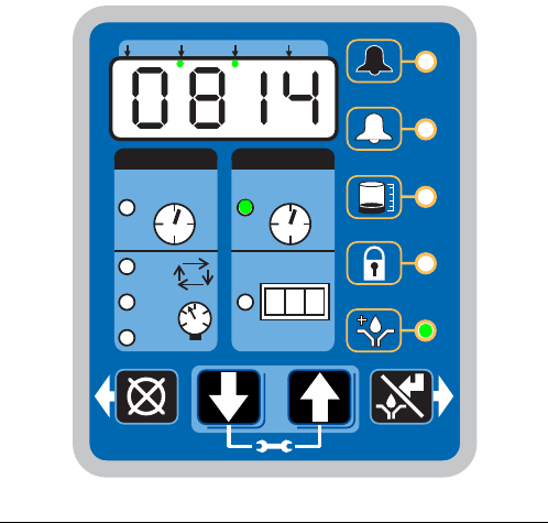
Run Mode
332305B 55
Additional Controls
Venting
In Max models a Vent Time can be set using the
Advanced Programming mode (page 47). This is typi-
cally done in a Pressure Based System (P1) to allow
injectors to reset.
• Unit vents for a set amount of time (not dis-
played).
• The LED’s next to C/P1, C/P2, C/P3 flash while
unit is venting.
• If Machine Count is set, the display will alternate
between machine counts remaining and backup
time (Max Model Rest Mode, page 53).
• If Machine Count has been set the LED next to
1-2-3 illuminates (FIG. 34, page 54).
• If Machine Count has not been set the display
shows OFF Time (See Time Control, page 51).
• If Machine Count has not been set the LED next
to the clock in the OFF field illuminates (See
Time Control, page 51).
Prelube / Prelube Delay
In all models a power OFF/ON cycle can be controlled
with the Prelube and Prelube Delay functions.
Prelube
The Prelube function has been selected. Prelube delay
is set to 00:00:
• Power to the unit cycles OFF then ON.
• Unit immediately begins a lubrication cycle.
• Max Model - display shows Cycle/Pres-
sure/Backup Time (See Max Model Lubrication
Mode Controls, page 52).
Prelube Delay
The Prelube function has been selected. Prelube delay
is set to something other than 00:00:
• Power to the unit cycles OFF then ON.
• Unit immediately begins the Prelube Delay
count down until the lubrication cycle begins.
• The LED next to the clock in the OFF field is illu-
minated (FIG. 36).
• The Prelube LED lights (FIG. 36).
• The display shows time remaining until lubrica-
tion cycle begins. The example shown in FIG. 36
shows 8 minutes and 14 seconds left until a
lubrication cycle begins.
FIG. 36
ON OFF
!
123
HH MM SS ##
MM : SS HH : MM
2
3
1
P
C
C
P
C
P
C
P

Run Mode
56 332305B
Manual Run Cycle
To run an extra (non-programmed) lubrica-
tion cycle, push the Manual Start button.
NOTE: Manual Run option is not available while unit is
in Vent Mode.
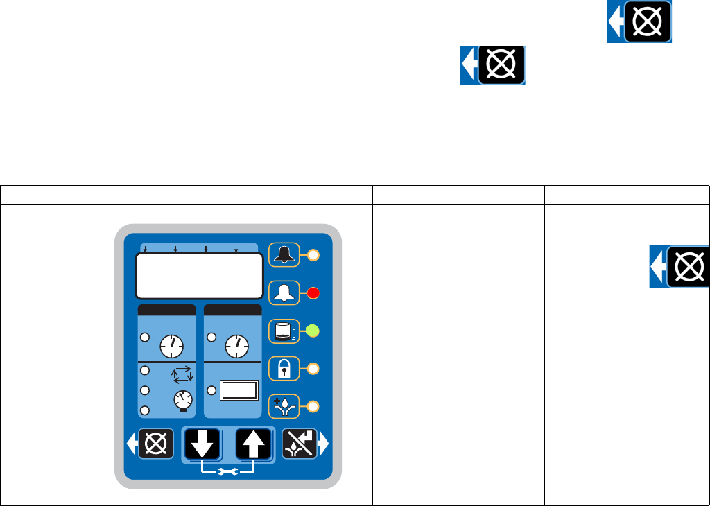
Alarms
332305B 57
Alarms
Any time a Fault / Warning occurs, a combination of LED’s will illuminate to notify you there is a problem and help
identify the kind of Fault / Warning has occurred.
• Faults and Warnings will not automatically clear.
• To clear an fault, press and hold the RESET button on the display button pad for 3 seconds.
• To clear a warning press and immediately release the RESET button.
Fault / Warning Scenarios
The following pages describe the most likely fault / warnings you could receive.
Alarm Type What it Looks Like What it Indicates Solution
Low Level
Warning
Level of lubricant in
reservoir is low and addi-
tional lubricant needs to be
added.
Unit continues to operate
as normal for a limited
period of time until a low
level alarm is triggered.
Add lubricant to reservoir.
After lubricant
is added,
press the
RESET but-
ton to clear the warning.
ON OFF
!
123
HH MM SS ##
MM : SS HH : MM
2
3
1
P
C
C
P
C
P
C
P
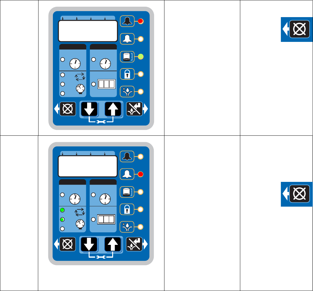
Alarms
58 332305B
Low Level
Fault
Level of lubricant in
reservoir is low and addi-
tional lubricant needs to be
added.
Unit stops pumping and
displays amount of accu-
mulated time since the
alarm was triggered.
Add lubricant to reservoir.
After lubri-
cant is
added press
and hold the
RESET button to clear
fault.
If repriming pump is
required, the low level
alarm time should be
decreased. See A-2:
Advanced Programming,
Low Level Alarm Time
page 47.
Cycle /
Pressure
Warning
System fails to relieve
pressure or a lubrication
cycle was not completed in
the user-defined amount of
time.
Unit will continue to oper-
ate for the number of lubri-
cation cycles set by the
warning retry parameter
(see Advanced Program-
ming, page 45).
If the warning condition
clears itself on the next
automatic lubrication cycle,
the warning is cleared and
the unit continues normal
operation.
Examine system to deter-
mine if you have a
plugged or broken line or
other component failure,
i.e., divider valve, injector.
Press the
RESET but-
ton to clear
warning.
ON OFF
!
123
HH MM SS ##
MM : SS HH : MM
2
3
1
P
C
C
P
C
P
C
P
ON OFF
!
123
HH MM SS ##
MM : SS HH : MM
2
3
1
P
C
C
P
C
P
C
P
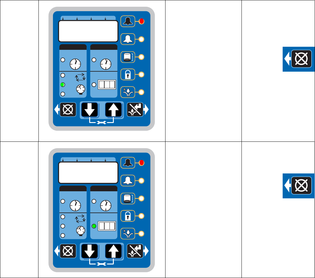
Alarms
332305B 59
Cycle /
Pressure
Fault
In pressure mode indi-
cates that unit is over pres-
surized or a lubrication
cycle was not completed in
the user-defined amount of
time.
In cycle mode indicates
that a cycle was not com-
pleted in the user-defined
amount of time.
LED corresponding to the
affected sensor input
blinks.
Could be more than one
sensor alarm at the same
time.
Examine system to deter-
mine if you have a
plugged or broken line or
other component failure,
i.e., divider valve, injector.
Press and
hold the
RESET but-
ton to clear
fault.
Machine
Count Fault
Unit has not received the
correct number of machine
counts in the user defined
Backup Time.
Examine system to deter-
mine if the machine sen-
sor is operating properly.
Press and
hold the
RESET but-
ton to clear
fault.
ON OFF
!
123
HH MM SS ##
MM : SS HH : MM
2
3
1
P
C
C
P
C
P
C
P
ON OFF
!
123
HH MM SS ##
MM : SS HH : MM
2
3
1
P
C
C
P
C
P
C
P
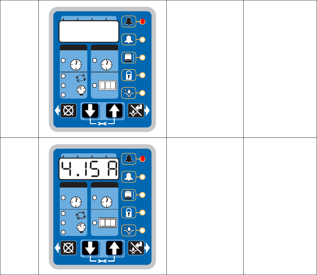
Alarms
60 332305B
System
Fault
An internal fault has
occurred.
Contact Graco Customer
Service.
Motor Cur-
rent Warn-
ing
The measured motor cur-
rent is above the recom-
mended operating
maximum value. Continued
use at excessive motor
currents could reduce life
or cause permanent dam-
age.
Examine system to make
sure it is operating cor-
rectly. A blocked line
could create excessive
motor current
Examine pump to ensure
that it is rotating properly.
If necessary, contact
Graco Customer Service.
ON OFF
!
123
HH MM SS ##
MM : SS HH : MM
2
3
1
P
C
C
P
C
P
C
P
ON OFF
!
123
HH MM SS ##
MM : SS HH : MM
2
3
1
P
C
C
P
C
P
C
P
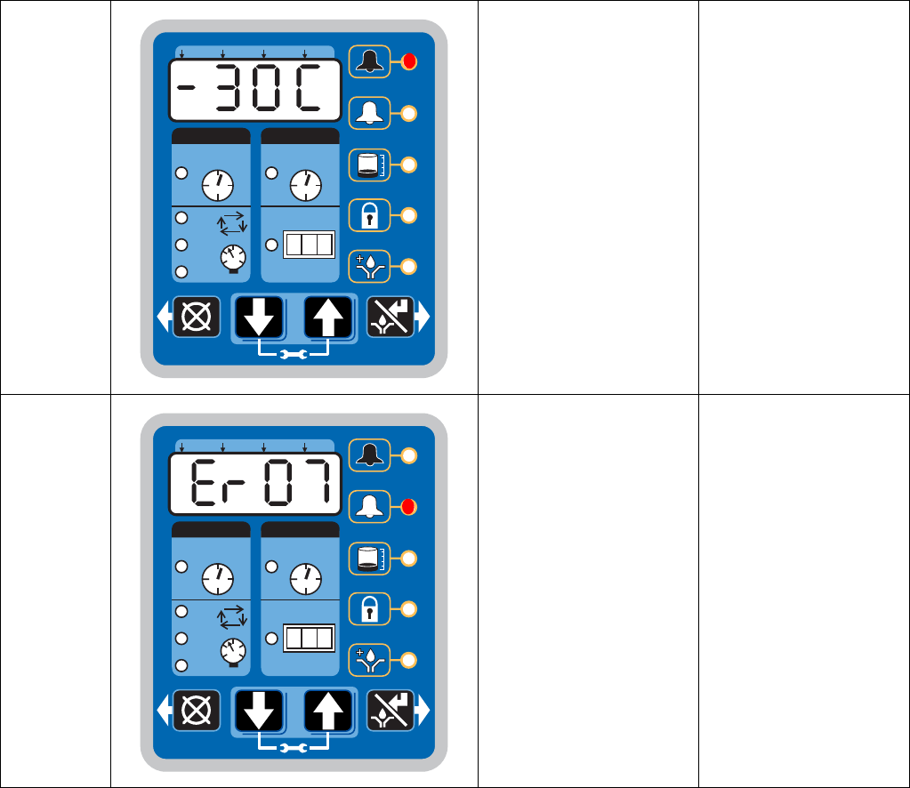
Alarms
332305B 61
Tempera-
ture Warning
The internal temperature of
the unit is out of its recom-
mended operating range.
Use of the unit outside of
the recommended tem-
perature range could cause
degraded system perfor-
mance and possible dam-
age.
Ensure the unit is used in
the correct operating envi-
ronment for the specific
temperature: -13° F to
158° F (-25° C to 70°C).
If necessary contact
Graco Customer Service.
USB Error An error occurred during a
DMS operation.
Read the Troubleshoot-
ing section of this manual
(page 62) for error num-
bers and fault descrip-
tions.
ON OFF
!
123
HH MM SS ##
MM : SS HH : MM
2
3
1
P
C
C
P
C
P
C
P
ON OFF
!
123
HH MM SS ##
MM : SS HH : MM
2
3
1
P
C
C
P
C
P
C
P
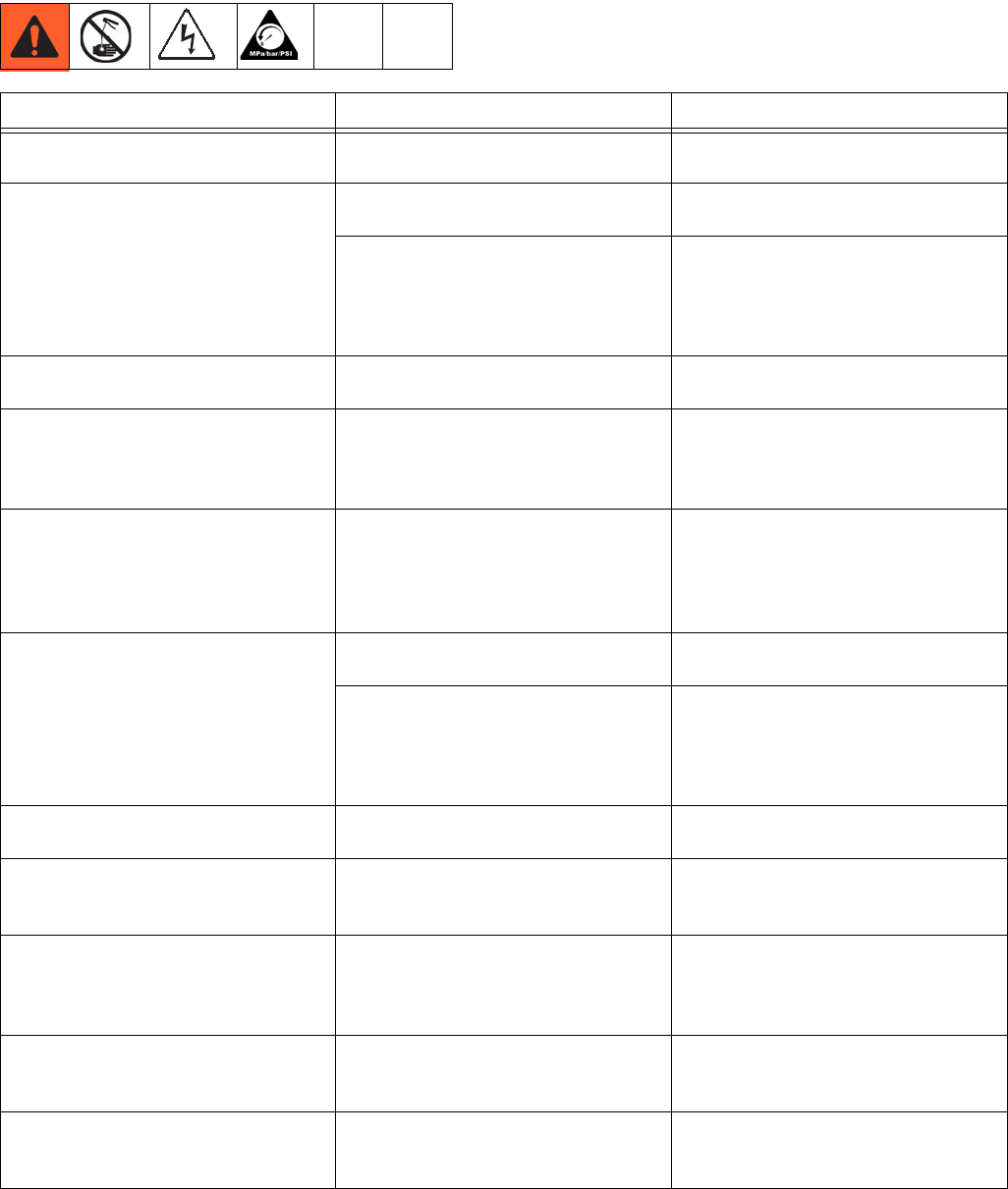
Troubleshooting
62 332305B
Troubleshooting
Problem Cause Solution
Unit does not power on Incorrect/loose wiring Refer to Installation instructions,
page 8.
Unit does not power on (DC models
only)
Tripped external fuse due to internal
component failure Contact Graco Customer Service.
Tripped external fuse due to pumping
non-cold weather lubricant in cold
weather -13°F (-25°C)
Replace lubricant with pumpable
lubricant, rated for environmental
conditions and application.
Replace fuse.
Unit does not power on (AC models
only)
Tripped internal power supply fuse
due to power supply failure Contact Graco Customer Service.
Can’t set desired ON/OFF times
Maximum duty cycle is 33% (2 min-
utes OFF for each minute ON)
Adhere to allowable duty cycle. Con-
tact Graco Customer Support if other
duty cycles are required for applica-
tion.
Unit is not operating based on the
time that was programmed
Time entered was misinterpreted as
MM:SS instead of HH:MM (or visa
versa)
Verify the unit was programmed as
intended, referencing programming
instructions. Note the dot designation
for hours, minutes, seconds on the
top row of the display.
Lubricant leaks past seal located on
the bottom of the reservoir
Reservoir retaining tabs are cracked
or broken
Replace reservoir.
Reservoir is being pressurized during
filling
Ensure vent hole is not plugged.
If problem persists, contact Graco
Customer Service or your local
Graco distributor for assistance.
Unit not pumping during ON cycle,
but controller lights and functions
Failed motor Replace unit.
Follower plate is not going down
Air is trapped in the reservoir
between the follower plate and lubri-
cant
Add grease following Loading
Grease instructions, page 24. Ensure
air is purged.
Pump takes several minutes before it
begins pumping at the highest pump
volume setting (no stroke adjust
spacers installed)
Pumping non-cold weather lubricant
in cold weather -13°F (-25°C)
Add 1 stroke adjust spacer and
adjust lube cycle time to accommo-
date the difference in pump volume
per stroke.
Dim display, unit is not operating
Tripped internal, resettable fuse due
to internal component failure or sen-
sor short circuit condition
Verify sensor and manual run inputs
have not created a short circuit condi-
tion. Cycle power.
Unit indicates a cycle or pressure
alarm before the lubrication cycle
could complete
The ON Time was not entered cor-
rectly
Refer to programming ON Time,
pages 31 and 52.

Troubleshooting
332305B 63
In an Injector System without sensor
feedback, unit does not vent properly
Vent valve time needs to be config-
ured
Refer to Advanced Programming to
set ON Time, page 45.
Display acts erratically
Faulty cycle/pressure wiring connec-
tion to unit
Unplug cycle/pressure cables from
G3. Plug cables in one at a time to
identify the faulty connection.
USB Error 00 Flash drive was removed during
operation
Keep the flash drive plugged in until
the unit has completed the operation.
USB Error 07
Flash drive unable to mount (initial-
ize)
• Unplug the flash drive and
re-install.
• Cycle power and re-install the
flash drive.
• Retry using a different flash
drive.
If any of the above do not rectify the
error, contact Graco Customer Ser-
vice.
USB Error 11
Pump program setting file not found Verify that the pump program setting
folder structure and file are stored
correctly on the flash drive. See Stor-
ing Pump Program Settings to the
Flash Drive, page 37 for instructions.
USB Error 12
Pump program settings directory not
found.
Verify that the pump program setting
folder structure and file are stored
correctly on the flash drive. See Stor-
ing Pump Program Settings to the
Flash Drive, page 37 for instructions.
USB Error 13
Bad pump program settings file The pump programs settings file is
corrupt. Restore file to the flash drive.
See Storing Pump Program Settings
to the Flash Drive, page 37 for
instructions.
All other USB errors
The following operations can be
attempted if another error occurs
using the USB.
• Unplug the flash drive and rein-
stall.
• Cycle power and re-install the
flash drive.
• Retry using a different flash
drive.
If any of the above do not rectify the
error, contact Graco Customer Ser-
vice.
Problem Cause Solution

Maintenance
64 332305B
Maintenance
Frequency Component Required Maintenance
Daily and at refill Zerk Fittings Keep all fittings clean using a clean
dry cloth. Dirt and/or debris can dam-
age pump and/or lubrication system.
Daily G3 Pump Unit and Reservoir Keep pump unit and reservoir clean
using a clean dry cloth.
Daily Display Keep display clean using a clean dry
cloth.
Monthly External Wiring Harness Verify external harnesses are secure.
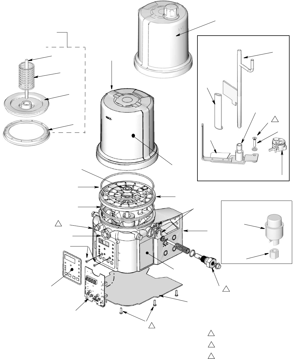
Parts - 2 Liter Models
332305B 65
Parts - 2 Liter Models
40a
44
14
1
42
13
18
17
34
36
33
37
41
21
30
15
4
3
31
Follower Plate
Models Only
43
Torque to 4 in. lbs (0.45 N.m)
1
Torque to 30 in. lbs (3.4 N.m)
2
Torque to 50 in. lbs (5.6 N.m)
3
2
3
40b
3
45
35
27
23
16 60
57
Low Level Grease Models Only
Low Level Oil Models Only
66
67
1
12
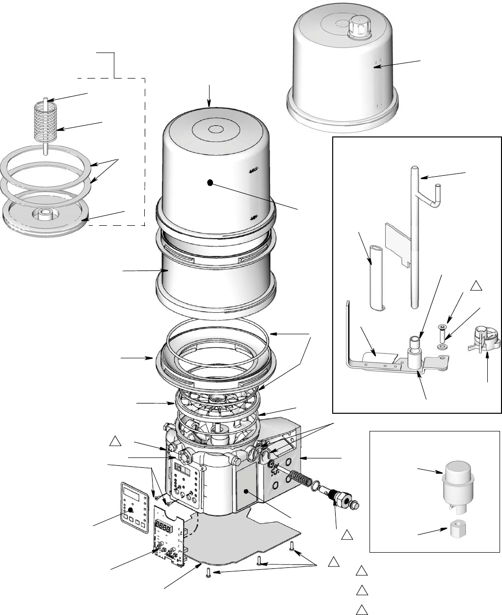
Parts - 4 Liter and Larger Models
66 332305B
Parts - 4 Liter and Larger Models
40a
44
35
14
1
41
13
18
17
34
16
36
33
37
42
21
30
15
4
3
31
Follower Plate
Models Only
43
Torque to 4 in. lbs (0.45 N.m)
1
Torque to 30 in. lbs (3.4 N.m)
2
Torque to 50 in. lbs (5.6 N.m)
3
2
3
61
62
40b
3
27 1
45
60
23
57
Low Level Grease Models Only
67
66
Low Level Oil Models Only
12
Parts
332305B 67
Parts
Ref Part Description Qty
1 BASE, three pump housing 1
3 278142 COVER, bottom, with seal 1
4 115477 SCREW, mach, torx pan hd 9
12 127079 RECT-RING, included in Kit
571042, 571069, 571179 1
13 124396
O-RING, 258, included in Kit
571042, 571044, 571045, 571069,
571179
2
14 PLATE, ricer 1
15 BEARING, ball 1
16
PADDLE, stirring, 2 Liter models
without follower plate - models
96G017, 96G019, 96G021,
96G023, 96G025,
96G030-96G032, 96G035-96G037,
96G098, 96G110, 96G125,
96G178, included in Kit 571044
1
PADDLE, stirring, 4 Liter models
without follower plate - models
96G088, 96G092, 96G096,
96G099, 96G103, 96G111,
96G118, 96G126, 96G141,
96G143, 96G145, 96G151,
96G153, 96G155, 96G157,
96G159, 96G160, 96G161,
96G162, 96G181, 96G183,
96G188
1
PADDLE, stirring, 8 Liter models
without follower plate - models
96G089, 96G093, 96G097,
96G100, 96G104, 96G112,
96G119, 96G127, 96G142,
96G144, 96G146, 96G152,
96G154, 96G156, 96G158,
96G177
1
PADDLE, stirring, 12 Liter models
without follower plate - models
96G105, 96G120, 96G164,
96G165
1
16
cont
PADDLE, stirring, 16 Liter models
without follower plate - models
96G106, 96G121, 96G166,
96G168, 96G169, 96G185
1
PADDLE, stirring, 2 Liter models
with follower plate - models
96G018, 96G020, 96G024,
96G026, 96G115, 96G132 included
in Kit 571045
1
PADDLE, stirring, 4Liter models
with follower plate - models
96G090, 96G094, 96G113,
96G116, 96G128, 96G133
1
17 PUMP, element, included in Kit
571041 1
18 16F368 SPACER, stroke adjust, included in
Kit 571041 2
21 278145 PLUG, pump, 3/4-16 2
23278136
PADDLE, low level, models
96G017-96G026, 96G030-96G032,
96G035-96G037, 96G088-96G090,
96G092-96G094, 96G096-96G100,
96G103-96G106, 96G110-96G113,
96G115, 96G116,
96G118-96G121, 96G125-96G128,
96G132, 96G133,
96G141-96G146, 96G151-96G162,
96G164-96G166, 96G168,
96G169, 96G177, 96G178,
96G181, 96G183, 96G185,
96G188
1
27 123025
SCREW, M6, models
96G017-96G021, 96G023-96G026,
96G030-96G032, 96G035-96G037,
96G088-96G090, 96G092-96G094,
96G096-96G100, 96G103-96G106,
96G110-96G113, 96G115,
96G116, 96G118-96G121,
96G125-96G128, 96G132,
96G133, 96G141-96G146,
96G151-96G162, 96G164-96G166,
96G168, 96G169, 96G177,
96G178, 96G181, 96G183,
96G185, 96G188
1
Ref Part Description Qty

Parts
68 332305B
30
‡258697
BOARD, circuit, Max, models
96G017-96G021, 96G023-96G026,
96G030-96G032, 96G035-96G037,
96G088-96G090, 96G092-96G094,
96G096, 96G097,
96G103-96G109, 96G113,
96G118-96G124, 96G128,
96G141-96G146,
96G151, 96G152, 96G155,
96G156, 96G159, 196G160,
96G164, 96G166, 96G168,
96G177, 96G178, 96G181,
96G183
‡262463
BOARD, circuit, Max, DMS™
models 96G098-96G100,
96G110-96G112, 96G115,
96G116, 96G125-96G127,
96G132, 96G133, 96G153,
96G154,96G157, 96G158,
96G161, 96G162, 96G165,
96G169, 96G174-96G176,
96G185, 96G186, 96G188
31 119228
SCREW, machine, flat head,
models 96G017-96G021,
96G023-96G026, 96G030-96G032,
96G035-96G037, 96G088-96G090,
96G092-96G094, 96G096-96G100,
96G103-96G113, 96G115,
96G116, 96G118-96G128,
96G132, 96G133,
96G141-96G146, 96G151-96G162,
96G164-96G166, 96G168,
96G169, 96G174-96G178,
96G181, 96G183-96G186, 96G188
2
3316A579 LABEL, safety 1
34 16A073
LABEL, overlay, models
96G017-96G021, 96G023-96G026,
96G030-96G032, 96G035-96G037,
96G088-96G090, 96G092-96G094,
96G096-96G100, 96G103-96G113,
96G115, 96G116,
96G118-96G128, 96G132,
96G133, 96G141-96G146,
96G151-96G162, 96G164-96G166,
96G168, 96G169,
96G174-96G178, 96G181,
96G183-96G186, 96G188
Ref Part Description Qty
35
WIPER, stirring, models without fol-
lower plate - models 96G017,
96G019, 96G021, 96G023,
96G025, 96G030-96G032,
96G035-96G037, 96G088,
96G089, 96G092, 96G093,
96G096-96G100, 96G103-96G106,
96G110-96G112, 96G118-96G121,
96G125-96G127, 96G141-96G146,
96G151-96G159, 96G160-96G162,
96G164, 96G165, 96G168,
96G169, 96G177, 96G178,
96G181, 96G183, 96G185,
96G188, included in Kit 571044
1
WIPER, stirring, models with fol-
lower plate - models 96G018,
96G020, 96G024, 96G026,
96G090, 96G094, 96G113,
96G115, 96G116, 96G128,
96G132, 96G133 included in Kit
571045
1
36 LABEL, brand 1
37 123741
FITTING, Zerk, grease, not
included on models
96G107-96G109, 96G122-96G124,
96G174-96G176, 96G186, 96G188
1
40a 24E984
RESERVOIR, 2 liter, grease,
96G017-96G021, 96G023-96G026,
96G030-96G032, 96G035-96G037,
96G098, 96G110, 96G115,
96G125, 96G132, 96G178,
included in Kit 571042, 571069
1
40b 16G021 RESERVOIR, 2 liter, oil, 96G107,
96G122, included in Kit 571179 1
40a 24B702
RESERVOIR, 4 liter, grease,
96G088, 96G090, 96G092,
96G094, 96G096, 96G099,
96G103, 96G111, 96G113,
96G116, 96G118, 96G126,
96G128, 96G133, 96G141,
96G143, 96G145, 96G151,
96G153, 96G155, 96G157,
96G159, 96G160, 96G161,
96G162, 96G181, 96G183,
included in Kit 571183
1
40b 16G020 RESERVOIR, 4 liter, oil, 96G108,
96G123, 96G175, 96G188 1
Ref Part Description Qty

Parts
332305B 69
40a
RESERVOIR, 8 liter, grease,
96G089, 96G093, 96G097,
96G100, 96G104, 96G112,
96G119, 96G127, 96G142,
96G144, 96G146, 96G152,
96G154, 96G156, 96G158,
96G177
1
40b
RESERVOIR, 8 liter, oil, 96G109,
96G124, 96G176, 96G186,
included in Kit 571182
1
40a RESERVOIR, 12 liter, 96G105,
96G120, 96G164, 96G165 1
40a
RESERVOIR, 16 liter, 96G106,
96G121, 96G166, 96G168,
96G169, 96G185
1
41
278139
SEAL, follower plate, 2 liter models
96G018, 96G020, 96G024,
96G026, 96G115, 96G132
1
16F472
SEAL, follower plate, 4 liter models
96G090, 96G094, 96G113,
96G116, 96G128, 96G133
2
42
PLATE, follower, 2 liter models
96G018, 96G020, 96G024,
96G026, 96G115, 96G132
1
PLATE, follower, 4 liter models
96G090, 96G094, 96G113,
96G116, 96G128, 96G133
1
43
ROD, follower plate, 2 liter models
96G018, 96G020, 96G024,
96G026, 96G115, 96G132
1
ROD, follower, 4 liter models
96G090, 96G094, 96G113,
96G116, 96G128, 96G133
44
SPRING, compression, 2 liter mod-
els 96G018, 96G020, 96G024,
96G026, 96G115, 96G132
1
SPRING, compression, 4 liter mod-
els 96G090, 96G094, 96G113,
96G116, 96G128, 96G133
1
45† 24D838
BAFFLE, low level, 2 liter models
96G017, 96G019, 96G021,
96G023, 96G025, 96G030 -
96G032, 96G035-96G037,
96G098, 96G110, 96G125,
96G178
1
Ref Part Description Qty
† 24E246
BAFFLE, low level, 4 liter models
96G088, 96G092, 96G096,
96G099, 96G103, 96G111,
96G118, 96G126, 96G141,
96G143, 96G145, 96G151,
96G153, 96G155, 96G157,
96G159, 96G160, 96G161,
96G162, 96G181, 96G183
1
†24F836
BAFFLE, low level, 8 liter models
96G089, 96G093, 96G097,
96G100, 96G104, 96G112,
96G119, 96G127, 96G142,
96G144, 96G146, 96G152,
96G154, 96G156, 96G158,
96G177
1
†24F923
BAFFLE, low level, 12 liter models
96G105, 96G120, 96G164,
96G165
1
†24F924
BAFFLE, low level, 16 liter models
96G106, 96G121, 96G166,
96G168, 96G169, 96G185
1
57 117156
BEARING, sleeve, models
96G017-96G021, 96G023-96G026,
96G035-96G037, 96G088-96G090,
96G092-96G094, 96G096-96G100,
96G103-96G106, 96G110-96G113,
96G115, 96G116,
96G118-96G121, 96G125-96G128,
96G132, 96G133,
96G141-96G146, 96G151-96G157,
96G160-96G162, 96G164,
96G165, 96G177, 96G178,
96G181, 96G183, 96G185
1
58196548
LABEL, models 96G019, 96G020.
96G025. 96G026, 96G032,
96G037, 96G092-96G094,
96G118-96G128, 96G132,
96G133, 96G145, 96G146,
96G166, 96G174-96G176, 96G183
1
Ref Part Description Qty
Parts
70 332305B
Replacement Danger and Warning labels, tags and
cards are available at no cost.
Also order Ref 27, Part No. 123025 and Ref 60, Part
No. 16D984
‡ Also order Ref 31, Part No. 119228 and Ref 34, Part
No. 16A073
† Also order Ref. 57, Part No. 117156 when ordering
this part.
60 16D984
WASHER, low level, models
96G017-96G021, 96G023-96G026,
96G030-96G032, 96G035-96G037,
96G088-96G090, 96G092-96G094,
96G096-96G100, 96G103-96G106,
96G110-96G113, 96G115,
96G116, 96G118-96G121,
96G125-96G128, 96G132,
96G133, 96G141-96G146,
96G151-96G162, 96G164,
96G165-96G168, 96G177,
96G178, 96G181, 96G183,
96G185
2
61
RESERVOIR, mid-section, 8 liter
models 96G089, 96G093, 96G097,
96G100, 96G104, 96G109,
96G112, 96G119, 96G124,
96G127, 96G142, 96G144,
96G146, 96G152, 96G154,
96G156, 96G158, 96G176,
96G166. 96G177, 96G186
1
RESERVOIR, mid-section, 12 liter
models 96G105, 96G120, 96G164,
96G165
2
RESERVOIR, mid-section, 16 liter
models 96G106, 96G121, 96G166,
96G168, 96G169, 96G185
3
62
ADAPTER, reservoir, models
96G088-96G090, 96G092-96G094,
96G096, 96G097,
96G099-96G100, 96G103-96G106,
96G108, 96G109,
96G111-96G113, 96G116,
96G118-96G121, 96G123,
96G124, 96G126-96G128,
96G133, 96G141-96G146,
96G151-96G162, 96G164-96G166,
96G168, 96G169,
96G175-96G177, 96G181,
96G183, 96G185, 96G186
1
66 126417
NUT, oil, models 96G107, 96G108,
96G109, 96G122, 96G123,
96G124, 96G175, 96G176,
96G186
67 24N806
FLOAT, oil, models 96G107,
96G108, 96G109, 96G122, 96G123,
96G124, 96G175, 96G176, 96G186,
96G188
Ref Part Description Qty
200
126217 CABLE,15 ft (4.5 m), SOOW
w/7pos, 3 pin, 90 deg 1
126218 CABLE, 15 ft (4.5 m), SOOW w/7
pos, 5 pin, 90 deg 1
126219 CABLE, 20 ft (6.1 m), SOOW, w/7
pos, 5 pin, 90 deg 1
126220 CABLE, 30 ft (9.1m) SOOW, w/7
pos, 5 pin, 90 deg
16U790 CABLE, DIN, bare) 1
201
124300 CABLE, M12, 15 ft., 4 wire, straight
male to flying leads 1
124333 CABLE, M12, 15 ft., 4 wire, straight
male to female 1
202
124301 CONNECTOR, Eurofast, fem,
straight, 4Pin 1
124594 CONNECTOR, Eurofast, 4 Pin 1
124595 CONNECTOR, Eurofast, 5 Pin 1
Ref Part Description Qty
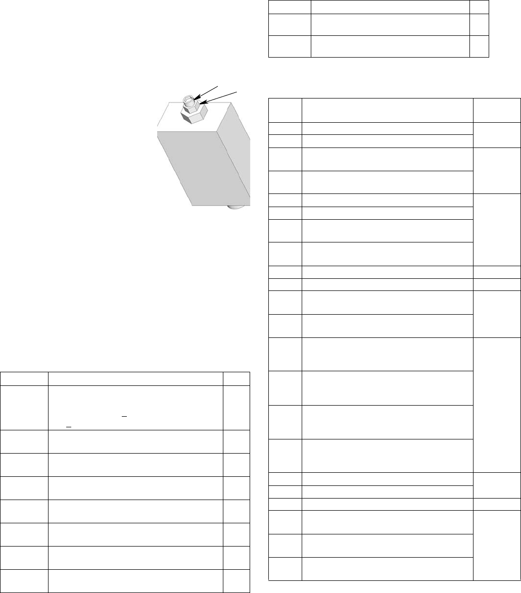
Parts
332305B 71
Pressure Relief Valves
Important Information regarding Pressure Relief
Valve 16C807.
Pressure Relief Valve 16C807 can only be used on
the G3 Pump. It is not intended for use with any other
products.
The pressure relief valve uses a
pressure adjustment screw (a) to
set the pressure release point. It
is not intended as a way to
relieve pressure during normal
operation, but as a protective
measure in the event there is an
unintended pressure increase in
the system. Do not use this pres-
sure relief valve a means of
relieving pressure in day-to-day,
normal cycle operation.
The pressure adjustment screw
will require periodic adjustments.
Whenever the valve is set/adjusted (after the set point is
found) it is important to ensure that the valve is not bot-
tomed out and there is at least 1/2 turn of adjustment
remaining. This is determined by turning the screw (a)
1/2 turn and then back turning it out again.
NOTE: Turning adjustment screw (a) clockwise
increases pressure.
Fuses
Installation and Repair Kits
Part Description Qty
16C807
VALVE, pressure relief, 500-3500 psi (3.44
MPa, 34.4 bar - 24.1 MPa, 241 bar), Set
pressure 3000 psi + 10% (20.68 MPa, 206.8
bar + 10%) Included in Kit 571028
1
563156 VALVE, pressure relief, 750 psi (5.17 MPa,
51.71 bar) 1
563157 VALVE, pressure relief, 1000 psi (6.89 MPa,
68.95 bar) 1
563158 VALVE, pressure relief, 1500 psi (10.34 MPa,
103.42 bar) 1
563159 VALVE, pressure relief, 2000 psi (13.78 MPa,
137.89 bar) 1
563160 VALVE, pressure relief, 2500 psi (17.23 MPa,
172.36 bar) 1
563161 VALVE, pressure relief, 3000 psi (20.68 MPa,
206.84 bar) 1
563190 VALVE, pressure relief, 5500 psi (37.92 MPa,
379.21 bar) 1
a
ti15644
b
a = adjustment screw
b = locking nut
Part Description Qty
571039 FUSE, 12 volt DC 1
571040 FUSE, 24 volt DC 1
Kit No. Description
Manual
Number
571026 KIT, output union, 3 pump 3A0523
571063 KIT, output union, 2 pump
571028 KIT, return to reservoir NPT, includes pres-
sure relief valve 16C807 3A0525
571071 KIT, return to reservoir BSPP, includes pres-
sure relief valve 16C807
571030 KIT, remote manual run, 12 volt DC
3A0528
571031 KIT, remote manual run, 24 volt DC
571032 KIT, remote manual run, 12 volt DC, with
cable
571033 KIT, remote manual run, 24 volt DC with
cable
571036 KIT, cover with “G” label NA
571041 KIT, pump element, includes Ref 17, 18, 33 3A0533
571042 KIT, repair, 2 liter reservoir, includes Ref 13,
36, 40 3A0534
571069 KIT, repair, 2 liter reservoir, for models with
follower plate, includes Ref 13, 36, 40
571044
KIT, replacement, paddle, 2 liter, for models
without follower plate, includes Ref 13, 16,
35, 57
3A0535
571045
KIT, replacement, paddle, 2 liter, for models
with follower plate, includes Ref 13, 16,
35,40a, 42, 57
571046
KIT, replacement, paddle, 4-16 liter, for
models without follower plate, includes Ref
13, 16, 35, 57
571047
KIT, replacement, paddle, 4 liter, for models
with follower plate, includes Ref 13, 16, 35,
57
571058 KIT, output adapter, NPT 3A0522
571070 KIT, output, adapter, BSPP
571060 KIT, fill, zerk, leakproof NA
571179 KIT, repair, reservoir oil, 2 liter models,
includes Ref 13, 36, 40b
3A0534571182 KIT, repair, reservoir, oil 4 liter models,
includes Ref 13, 36, 40b
571183 KIT, repair, reservoir, grease, 4 liter models,
includes Ref 13, 36, 40b
Technical Data
72 332305B
Technical Data
A
Maximum Working Pressure 5100 psi (35.1 MPa, 351.6 bar)
Power
100-240 VAC 88 - 264 VAC; 0.8 A current, 90 VA Power, 47/63 Hz,
Single phase, inrush/locked rotor, max 40A (1ms)
12 VDC 9 - 16 VDC; 5 A current, 60 W, inrush/locked rotor 12 A
24 VDC 18 - 32 VDC; 2.5 A current, 60 W, inrush/locked rotor 6 A
Outputs - Alarm Relay
Rated Load Resistive: 0.4 A at 125 VAC, 2 A at 30 VDC
Inductive: 0.2 A at 125 VAC, 1 A at 30 VDC
Max Operation Voltage Resistive: 250 VAC, 220 VAC
Inductive: 250 VAC, 220 VDC
Max Operating Current Resistive: 3 A (AC), 3A (DC)
Inductive: 1.5 A (AC), 1.5 A (DC)
Max Switching Capacity Resistive: 50 VA, 60 W
Inductive: 25 VA, 30 W
Min Permissible Load Resistive: 10 µA, 10m VDC
Inductive: 10 µA, 10m VDC
Outputs - Vent Valve
Required Vent Valve Type Normally closed
Output Voltage
100/240 VAC 24 VDC
12 VDC Input Voltage
24 VDC Input Voltage
Max Operating Current 2 A
Max Operating Power 48 W
Inputs - Cycle Pressure, 1, 2, 3, Machine Count
Required Switch Type Normally open (sink, source, or dry contact)
Sensor Voltage
100/240 VAC 24 VDC
12 VDC Input Voltage
24 VDC Input Voltage
Load Current
100/240 VAC 22mA @ 24 VDC
12 VDC 11mA @ 12 VDC
24 VDC 22mA @ 24 VDC
Maximum Residual Voltage
100/240 VAC 4 V
12 VDC 2 V
24 VDC 4 V
Maximum Off Current
100/240 VAC 1.5 mA
12 VDC 1 mA
24 VDC 1.5 mA
Input Impedance 1.1 K
Response Time 60 ms
Cycle Rate 8.0 Hz (50% duty cycle)

Technical Data
332305B 73
Dimensions
Fluid
Grease Models Grease NLGI 000 - #2
Oil Models At least 40 cSt oil.
Pumps Up to 3
Pump Output 0.12 in.3 (2 cm3) / minute per outlet - 2 spacers
0.18 in.3 (3 cm3) / minute per outlet - 1 spacer
0.25 in.3 (4 cm3) / minute per outlet - 0 spacers
Pump Outlet 1/4-18 NPSF. Mates with 1/4-18 NPT male fittings
Reservoir Size 2, 4, 8, 12, 16 Liters
IP Rating IP69K
Sensor Inputs 3 (any of pressure or cycle)
1 (machine count)
Ambient Temps -40°F - 158°F (-40°C to 70°C)
Weight (Dry - includes power cord and plug)
Without follower plate 13.3 lbs (6.03 kg)
With follower plate 14.2 lbs (6.44 kg)
Wetted Parts nylon 6/6 (PA), trogamid T5004-060, zinc plated steel,
carbon steel, alloy steel, stainless steel, nitrile rubber
(buna-N), bronze, nickel plated alnico, chemically lubri-
cated acetal, aluminum, PTFE, Grillamid
Sound Data <60 dB
Model Height Width Depth
Inches cm Inches cm Inches cm
2L 13.25 33.65 8.00 20.32 9.00 22.86
4L 14.50 36.83 9.25 23.50 10.00 25.40
8L 18.50 47.00 9.25 23.50 10.00 25.40
12L 23.00 58.42 9.25 23.50 10.00 25.40
16L 27.50 69.85 9.25 23.50 10.00 25.40
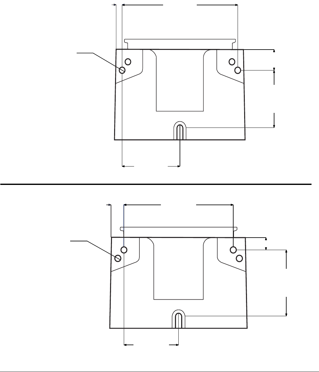
Technical Data
74 332305B
Mounting Pattern
(For correct mounting configuration, choose either Option 1 or Option 2). See P/N 126916 template.
FIG. 37
0.367inch
9.3 mm
2x Ø 0.366 inch
9.3 mm
3.544 inch
90.0 mm
7.087 inch
180.0 mm
1.180 inch
30.0 mm
3.268 inch
83.0 mm
0.722 inch
18.3 mm
2x Ø 0.366 inch
9.3 mm
3.189 inch
81.0 mm
6.378 inch
162.0 mm
3.740 inch
95.0 mm
0.708 inch
18.0 mm
Option 1
Option 2

Notes
332305B 75
Notes
All written and visual data contained in this document reflects the latest product information available at the time of publication.
Graco reserves the right to make changes at any time without notice.
For patent information, see www.graco.com/patents.
Original instructions. This manual contains English. MM 332305
Graco Headquarters: Minneapolis
International Offices: Belgium, China, Japan, Korea
GRACO INC. AND SUBSIDIARIES • P.O. BOX 1441 • MINNEAPOLIS MN 55440-1441 • USA
Copyright 2013, Graco Inc. All Graco manufacturing locations are registered to ISO 9001.
www.graco.com
revised April 2014
Graco Standard Warranty
Graco warrants all equipment referenced in this document which is manufactured by Graco and bearing its name to be free from defects in
material and workmanship on the date of sale to the original purchaser for use. With the exception of any special, extended, or limited warranty
published by Graco, Graco will, for a period of twelve months from the date of sale, repair or replace any part of the equipment determined by
Graco to be defective. This warranty applies only when the equipment is installed, operated and maintained in accordance with Graco’s written
recommendations.
This warranty does not cover, and Graco shall not be liable for general wear and tear, or any malfunction, damage or wear caused by faulty
installation, misapplication, abrasion, corrosion, inadequate or improper maintenance, negligence, accident, tampering, or substitution of
non-Graco component parts. Nor shall Graco be liable for malfunction, damage or wear caused by the incompatibility of Graco equipment with
structures, accessories, equipment or materials not supplied by Graco, or the improper design, manufacture, installation, operation or
maintenance of structures, accessories, equipment or materials not supplied by Graco.
This warranty is conditioned upon the prepaid return of the equipment claimed to be defective to an authorized Graco distributor for verification of
the claimed defect. If the claimed defect is verified, Graco will repair or replace free of charge any defective parts. The equipment will be returned
to the original purchaser transportation prepaid. If inspection of the equipment does not disclose any defect in material or workmanship, repairs
will be made at a reasonable charge, which charges may include the costs of parts, labor, and transportation.
THIS WARRANTY IS EXCLUSIVE, AND IS IN LIEU OF ANY OTHER WARRANTIES, EXPRESS OR IMPLIED, INCLUDING BUT NOT
LIMITED TO WARRANTY OF MERCHANTABILITY OR WARRANTY OF FITNESS FOR A PARTICULAR PURPOSE.
Graco’s sole obligation and buyer’s sole remedy for any breach of warranty shall be as set forth above. The buyer agrees that no other remedy
(including, but not limited to, incidental or consequential damages for lost profits, lost sales, injury to person or property, or any other incidental or
consequential loss) shall be available. Any action for breach of warranty must be brought within two (2) years of the date of sale.
GRACO MAKES NO WARRANTY, AND DISCLAIMS ALL IMPLIED WARRANTIES OF MERCHANTABILITY AND FITNESS FOR A
PARTICULAR PURPOSE, IN CONNECTION WITH ACCESSORIES, EQUIPMENT, MATERIALS OR COMPONENTS SOLD BUT NOT
MANUFACTURED BY GRACO. These items sold, but not manufactured by Graco (such as electric motors, switches, hose, etc.), are subject to
the warranty, if any, of their manufacturer. Graco will provide purchaser with reasonable assistance in making any claim for breach of these
warranties.
In no event will Graco be liable for indirect, incidental, special or consequential damages resulting from Graco supplying equipment hereunder, or
the furnishing, performance, or use of any products or other goods sold hereto, whether due to a breach of contract, breach of warranty, the
negligence of Graco, or otherwise.
FOR GRACO CANADA CUSTOMERS
The Parties acknowledge that they have required that the present document, as well as all documents, notices and legal proceedings entered into,
given or instituted pursuant hereto or relating directly or indirectly hereto, be drawn up in English. Les parties reconnaissent avoir convenu que la
rédaction du présente document sera en Anglais, ainsi que tous documents, avis et procédures judiciaires exécutés, donnés ou intentés, à la suite
de ou en rapport, directement ou indirectement, avec les procédures concernées.
Graco Information
For the latest information about Graco products, visit www.graco.com.
TO PLACE AN ORDER, contact your Graco distributor or call to identify the nearest distributor.
Phone: 612-623-6928 or Toll Free: 1-800-533-9655, Fax: 612-378-3590
