Graco 332637C Reactor 2 Elite Integrated Proportioning System Users Manual System, Repair Parts, English
2015-04-02
: Graco Graco-332637C-Reactor-2-Elite-Integrated-Proportioning-System-Users-Manual-686236 graco-332637c-reactor-2-elite-integrated-proportioning-system-users-manual-686236 graco pdf
Open the PDF directly: View PDF ![]() .
.
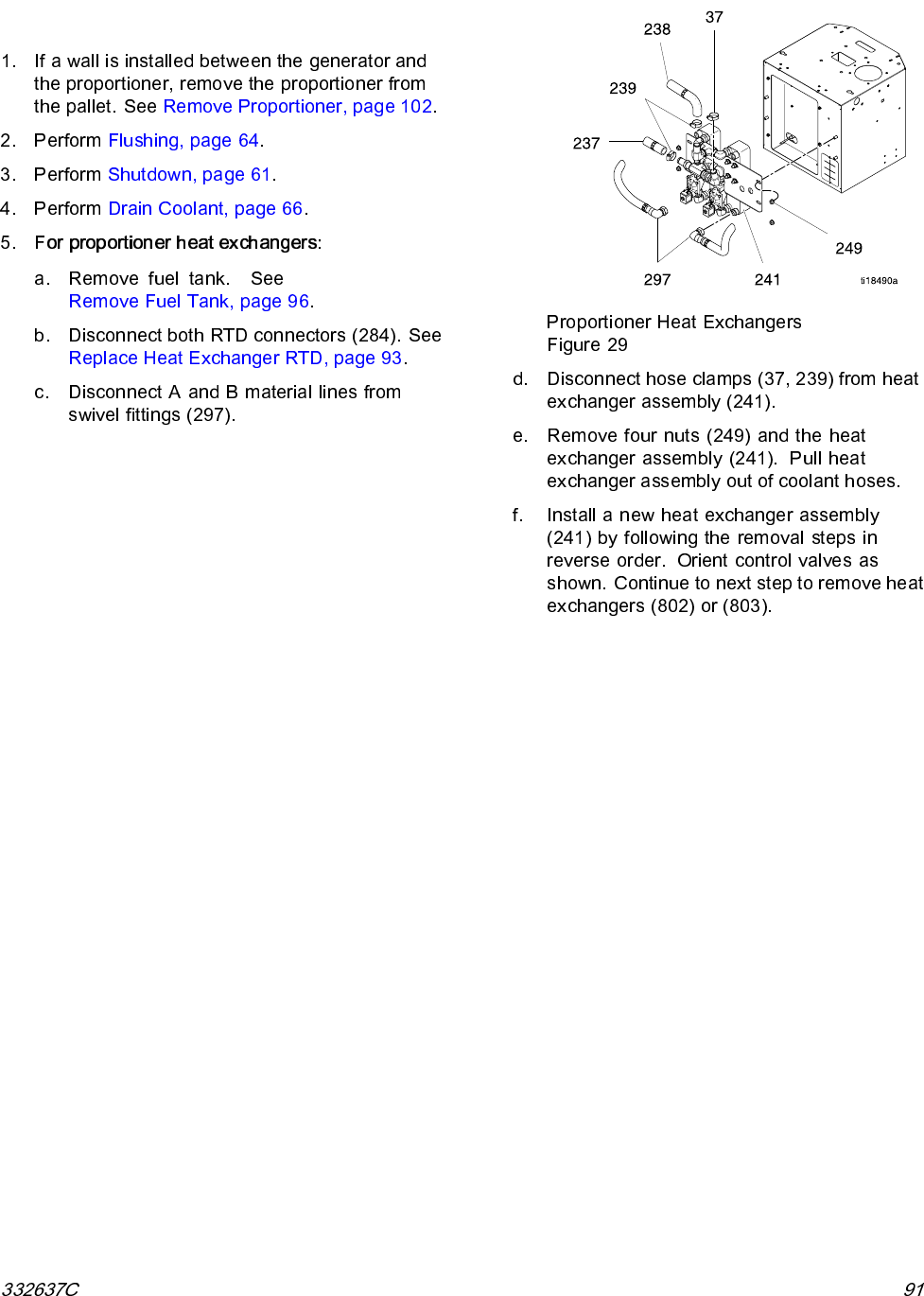
Page Count: 180 [warning: Documents this large are best viewed by clicking the View PDF Link!]
- toc
- Contents
- Warnings
- Important Isocyanate Information
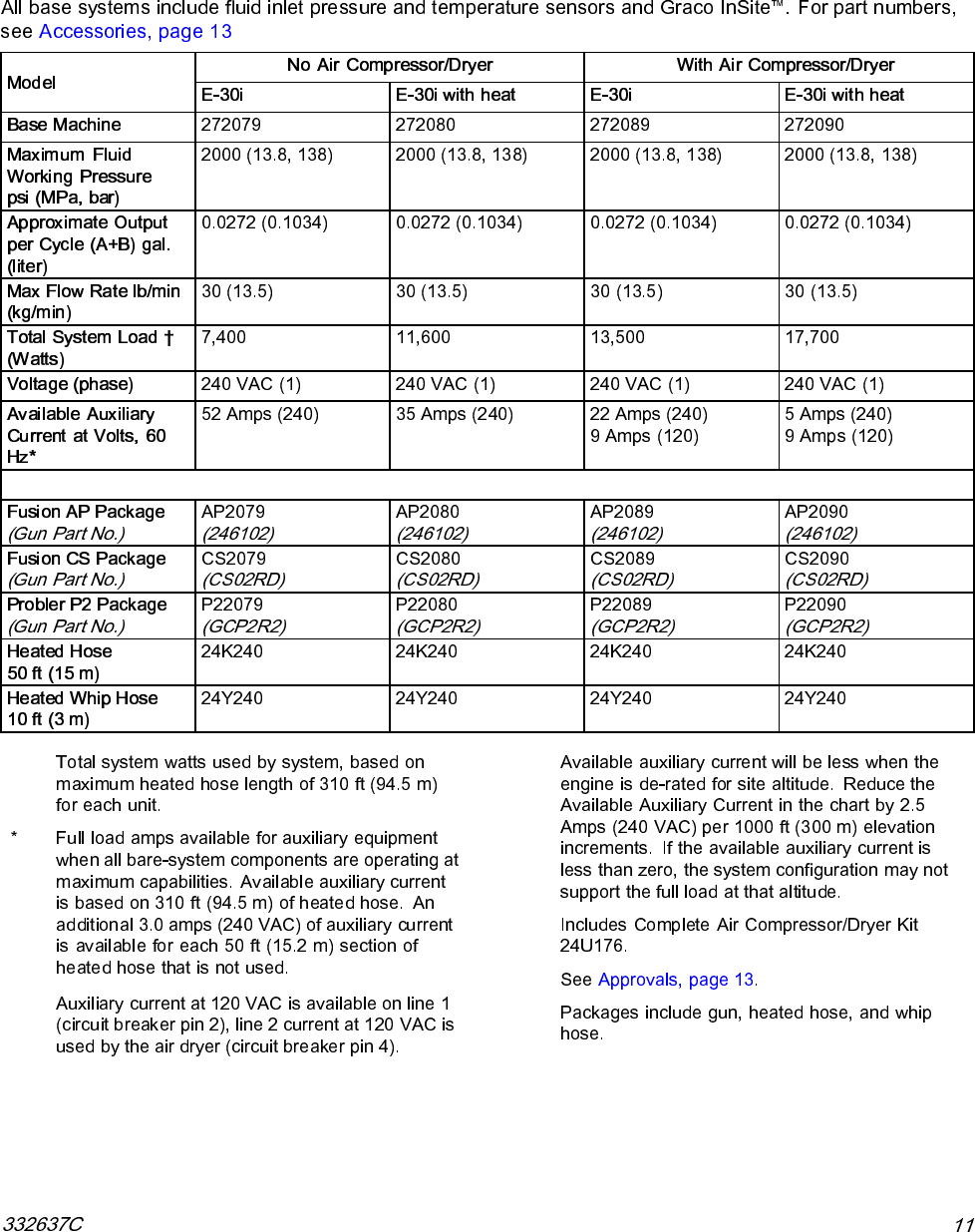
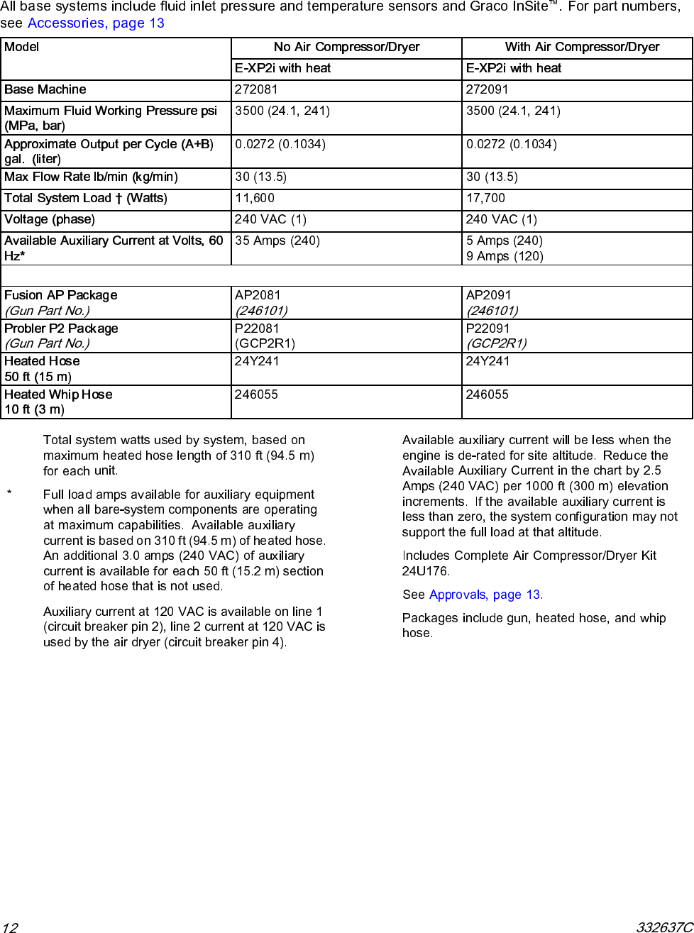
- Models
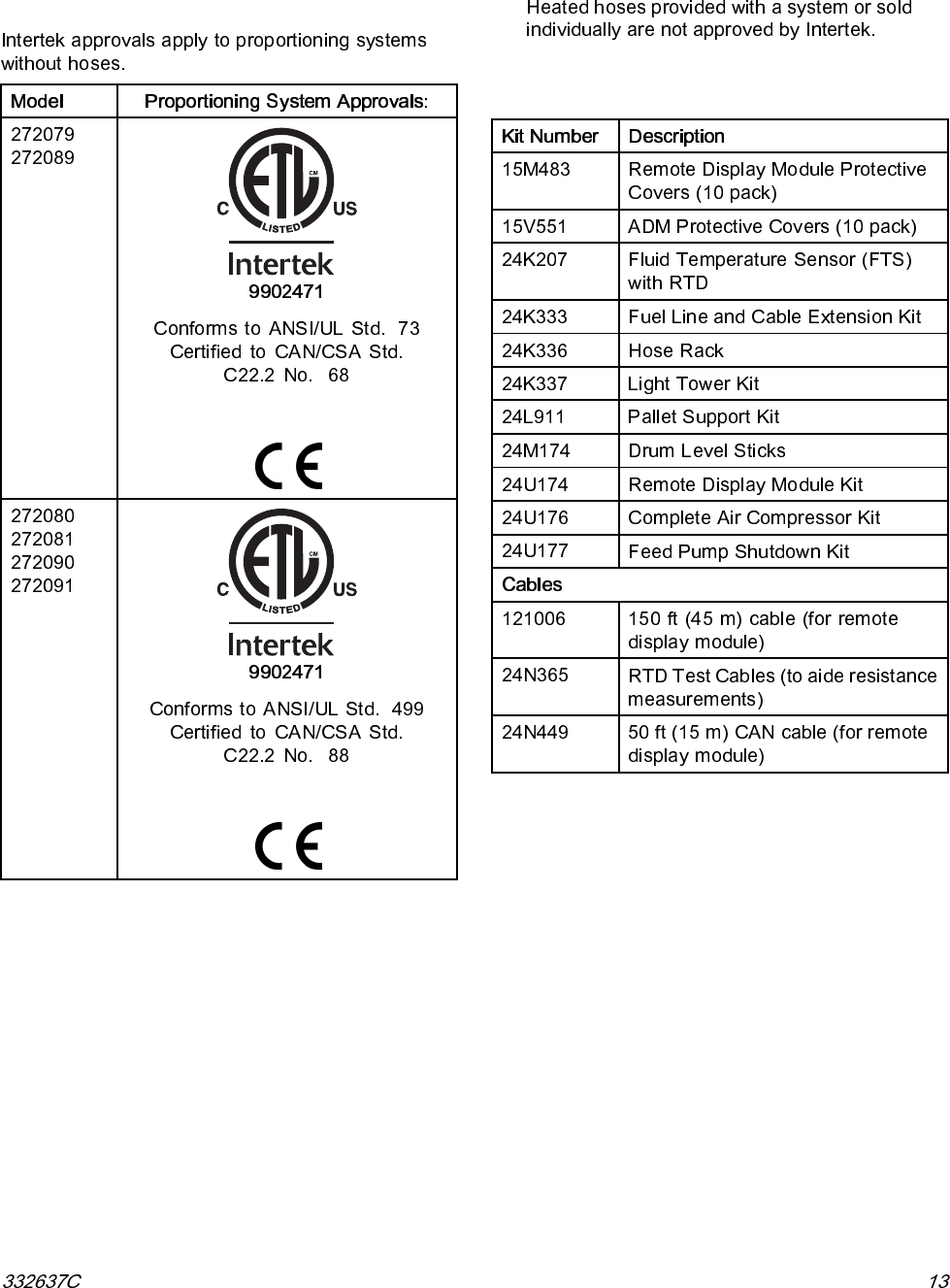
- Approvals
- Accessories
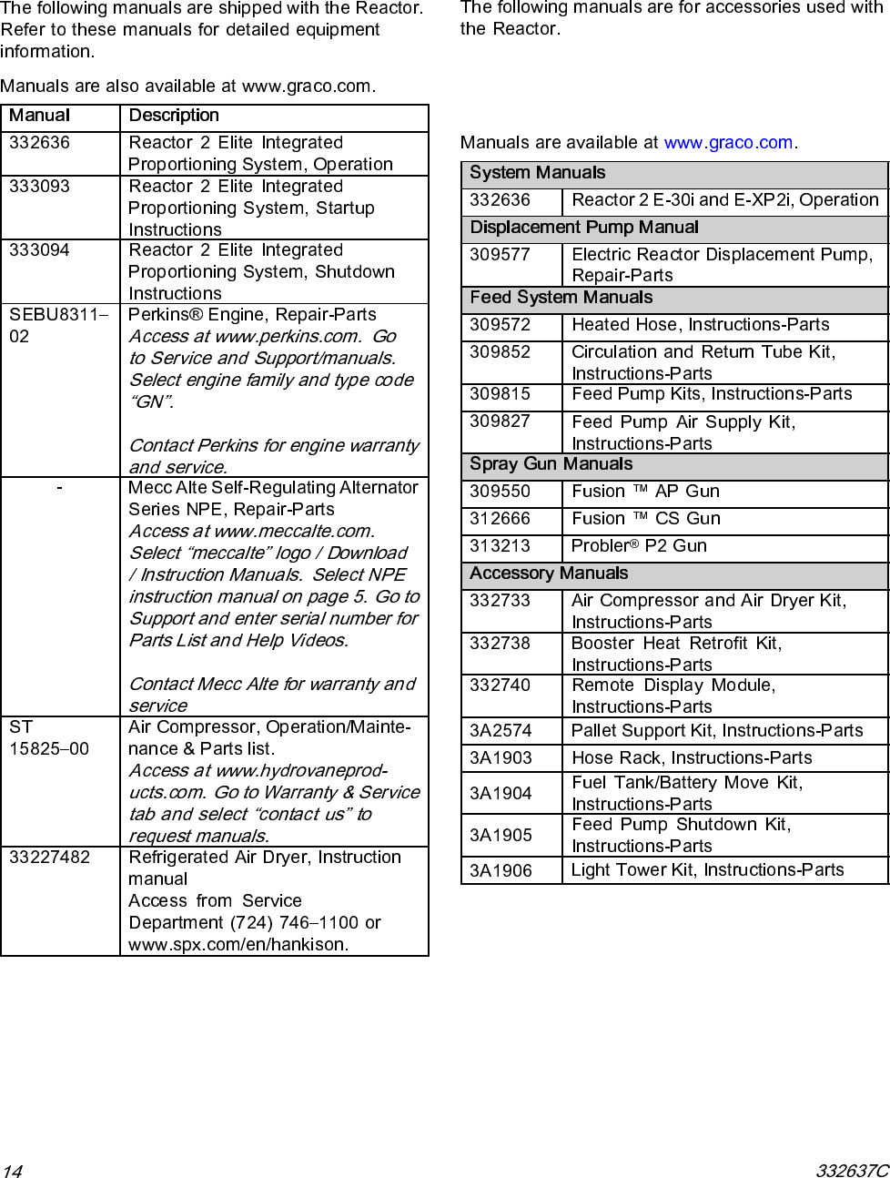
- Supplied Manuals
- Related Manuals
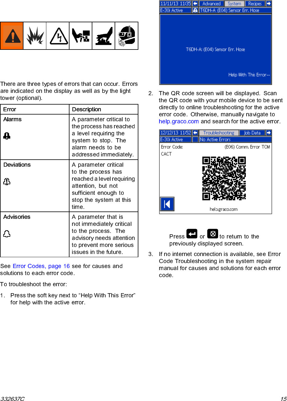
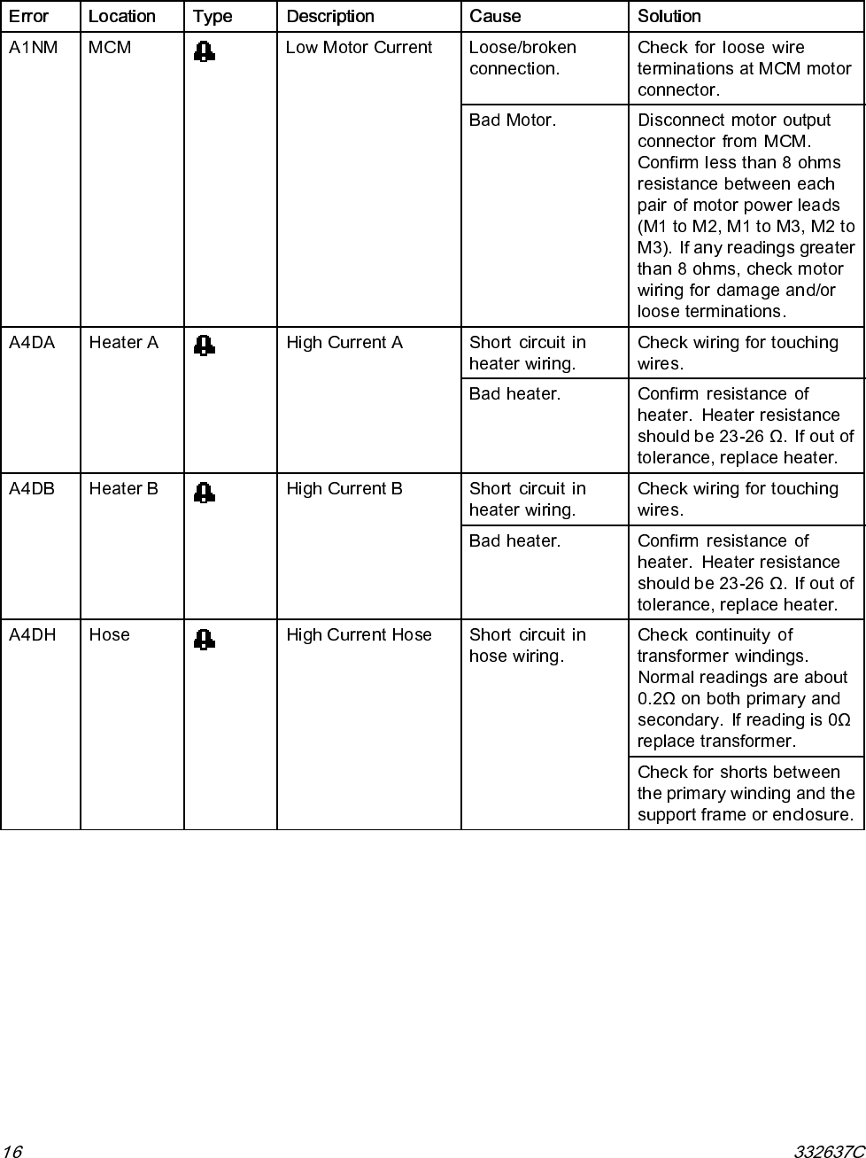
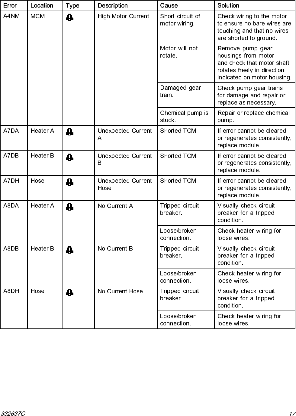
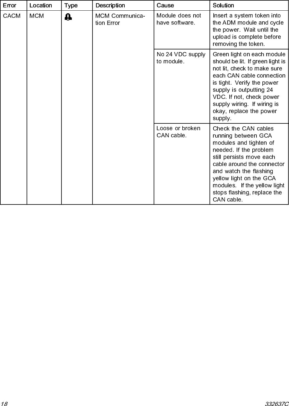
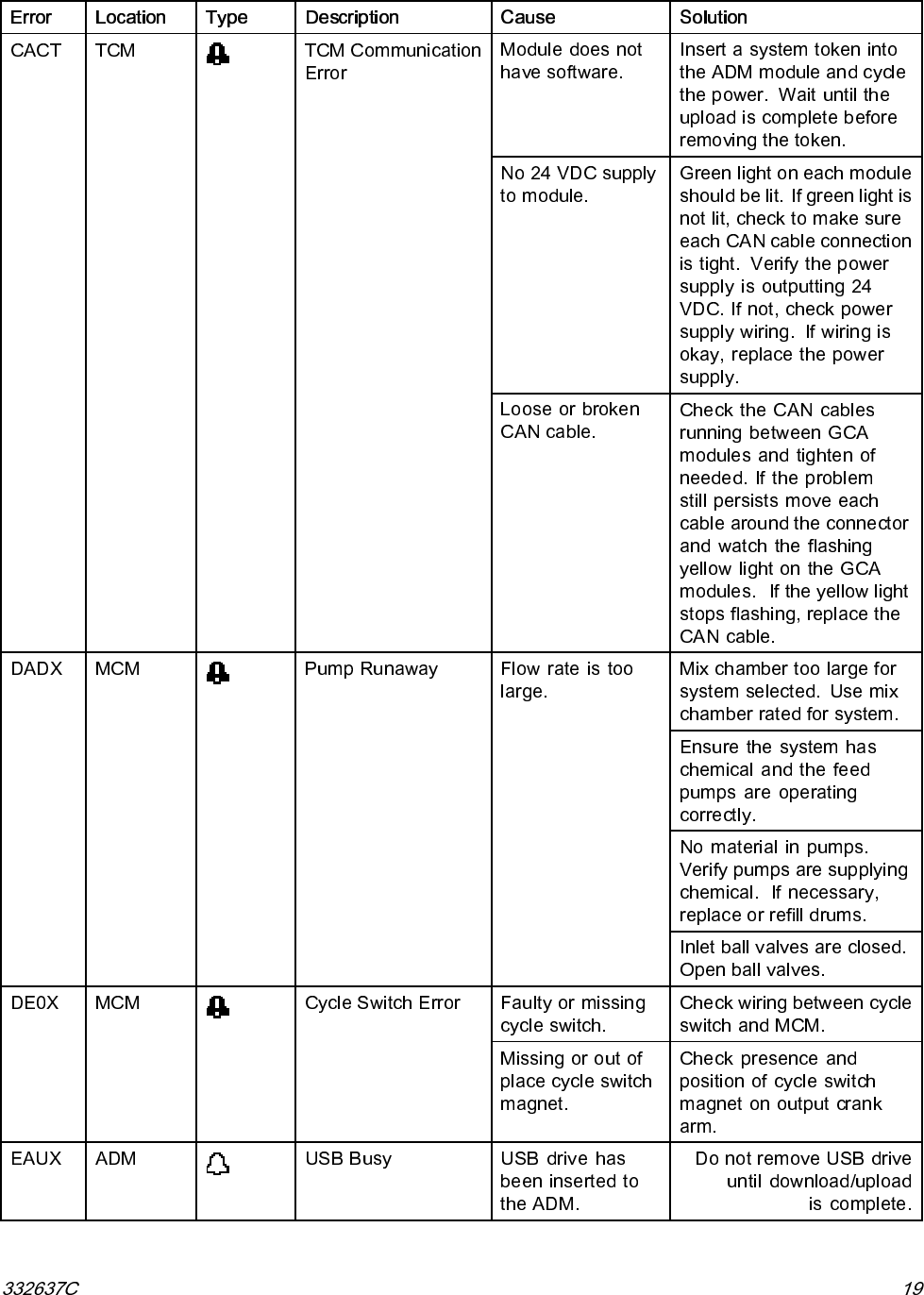
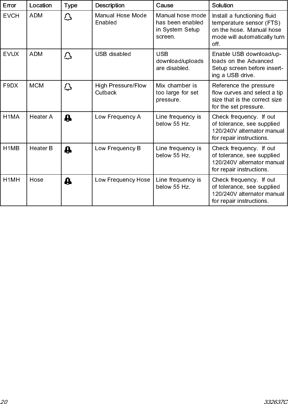
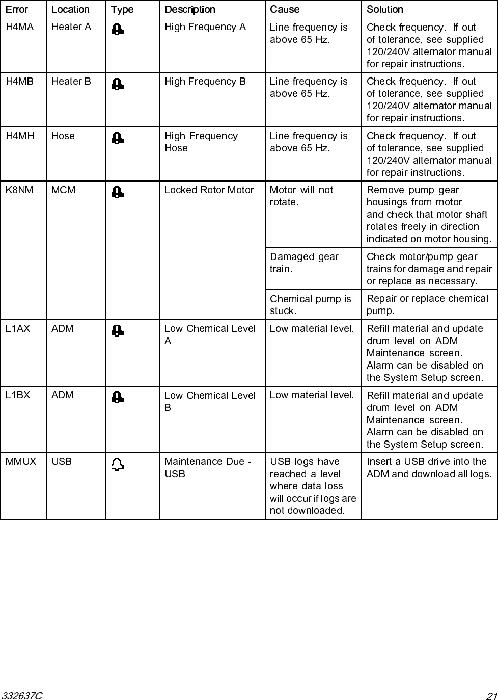
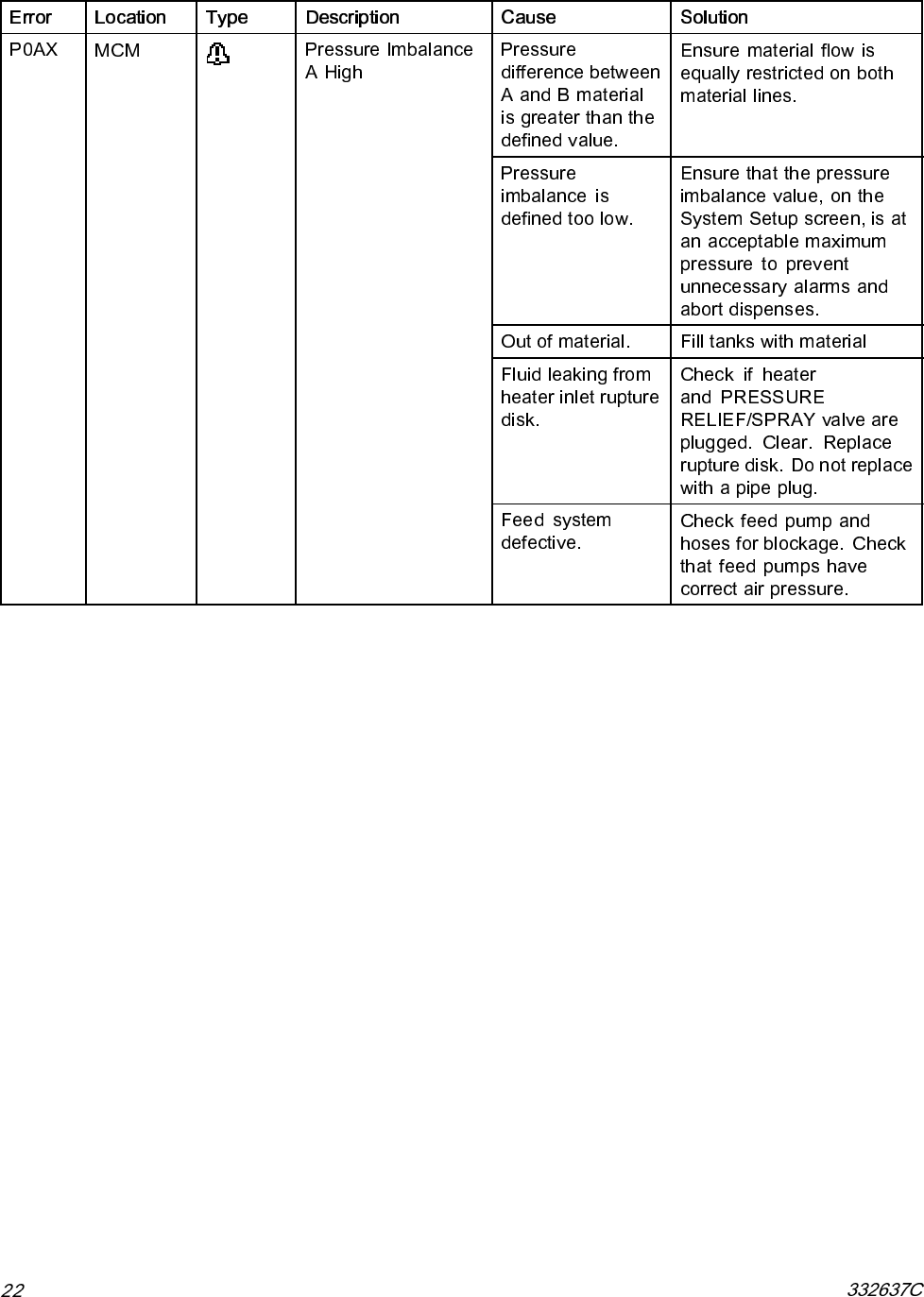
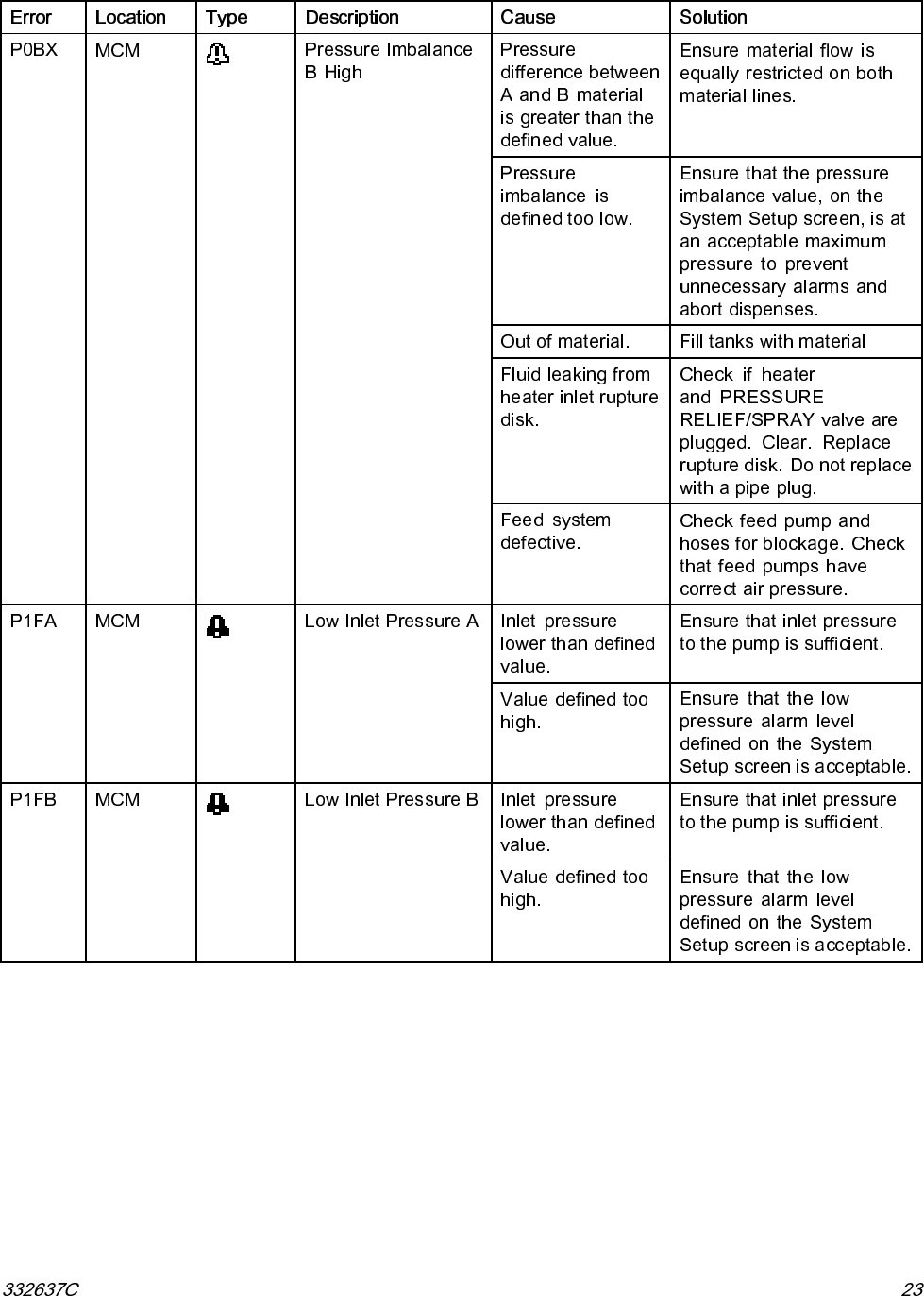
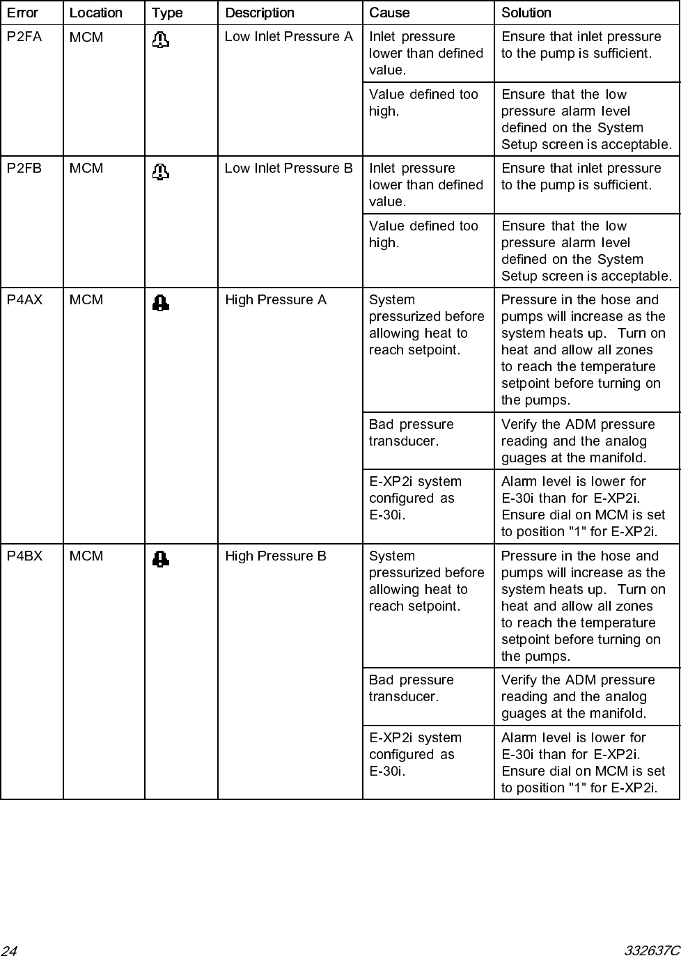
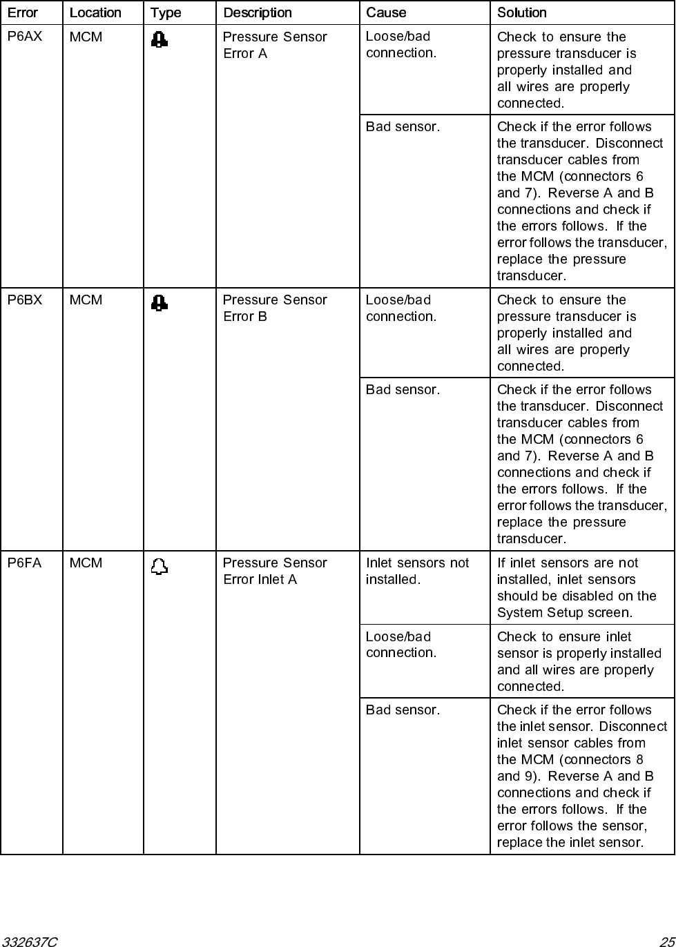
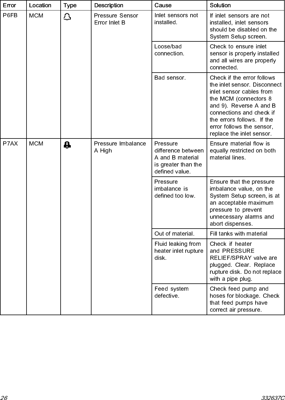
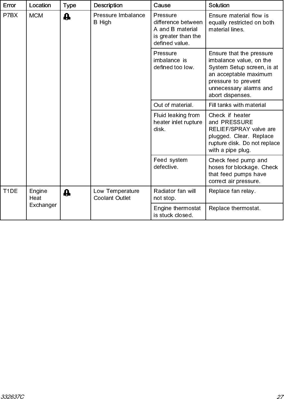
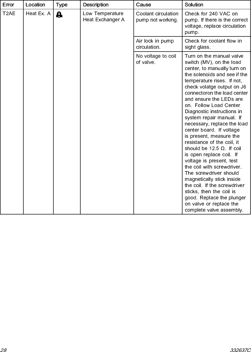
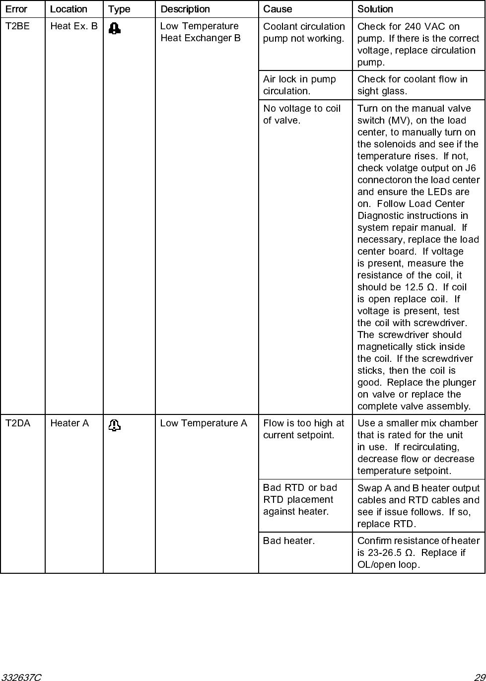
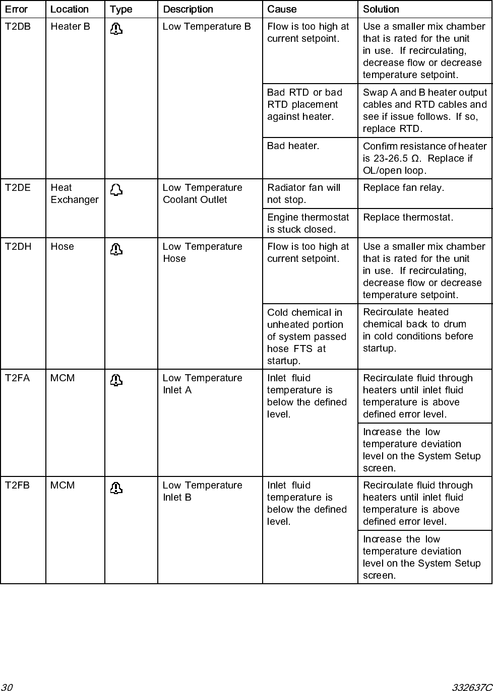
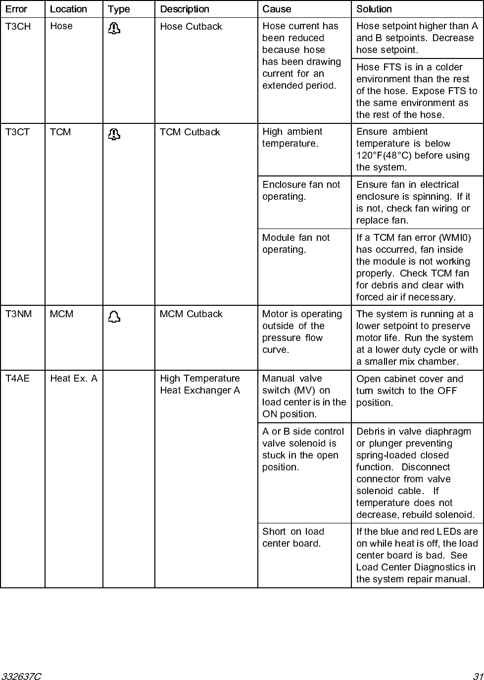
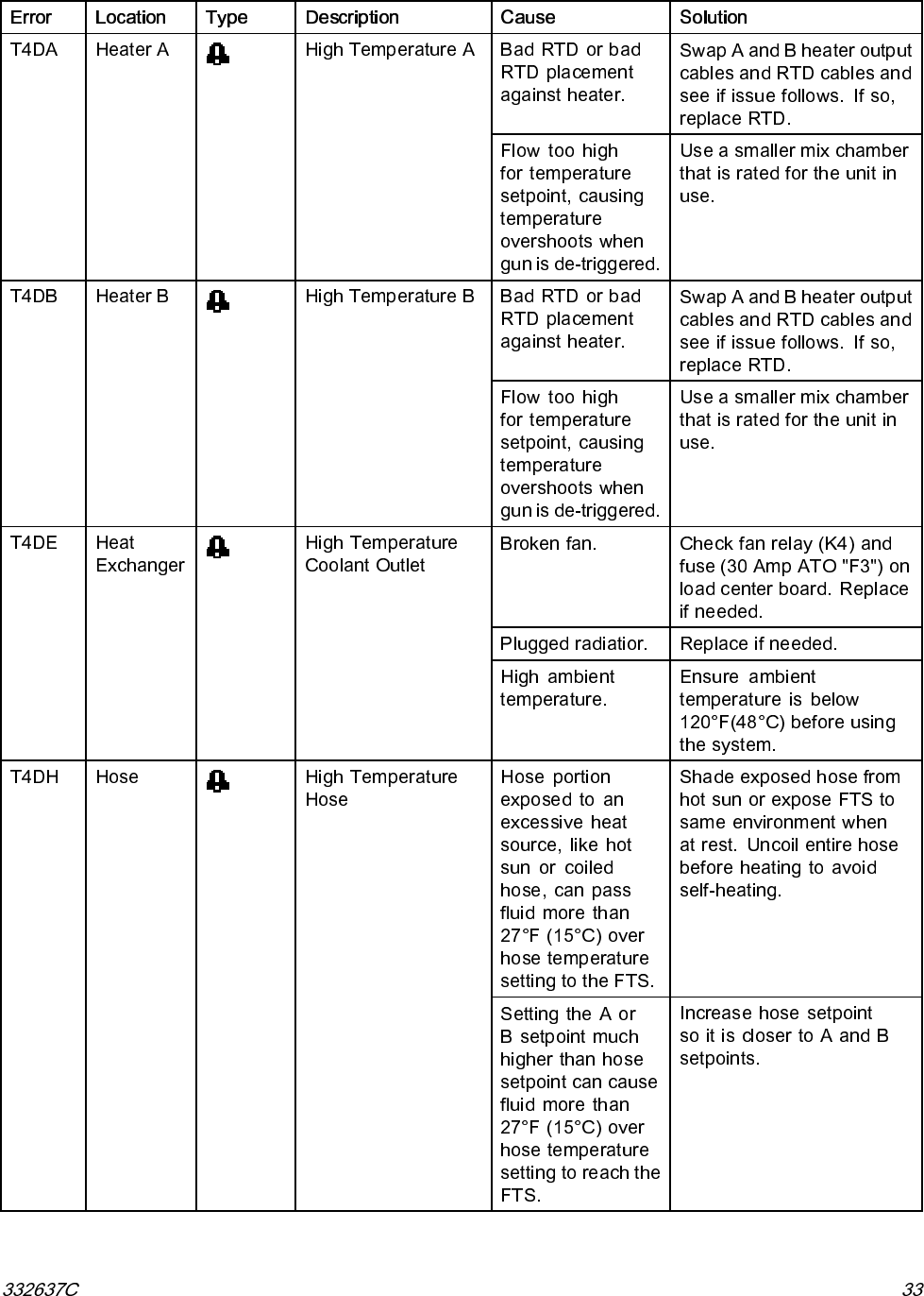
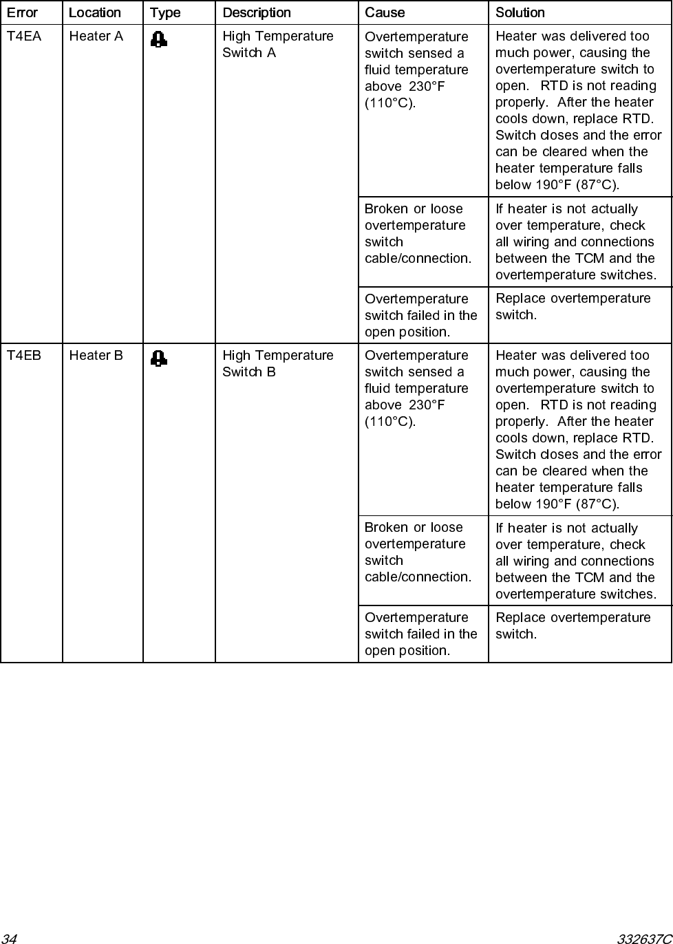
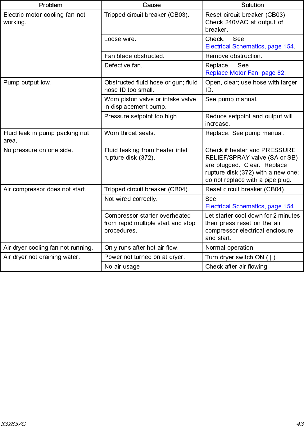
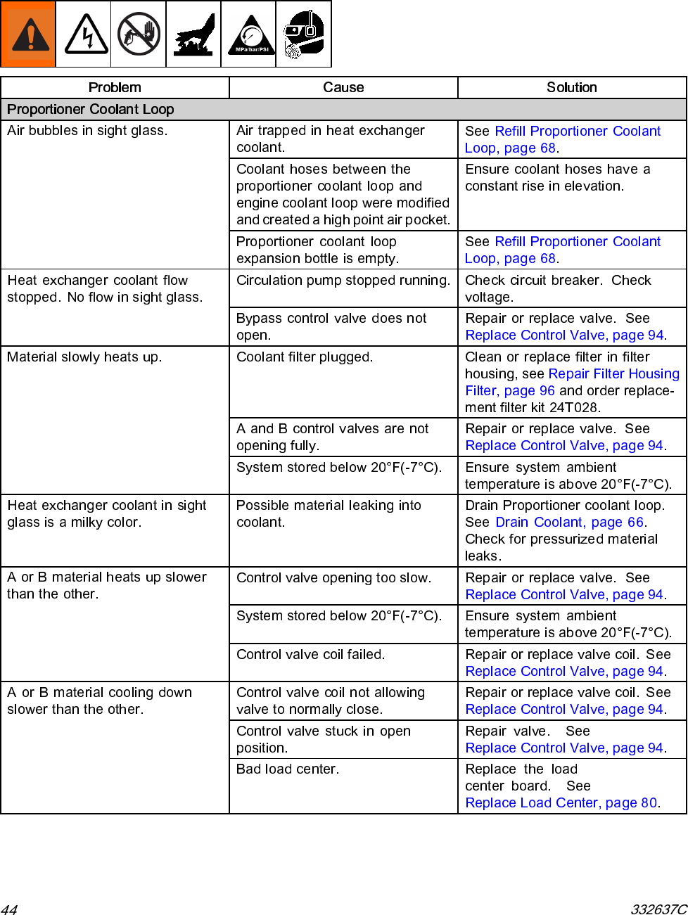
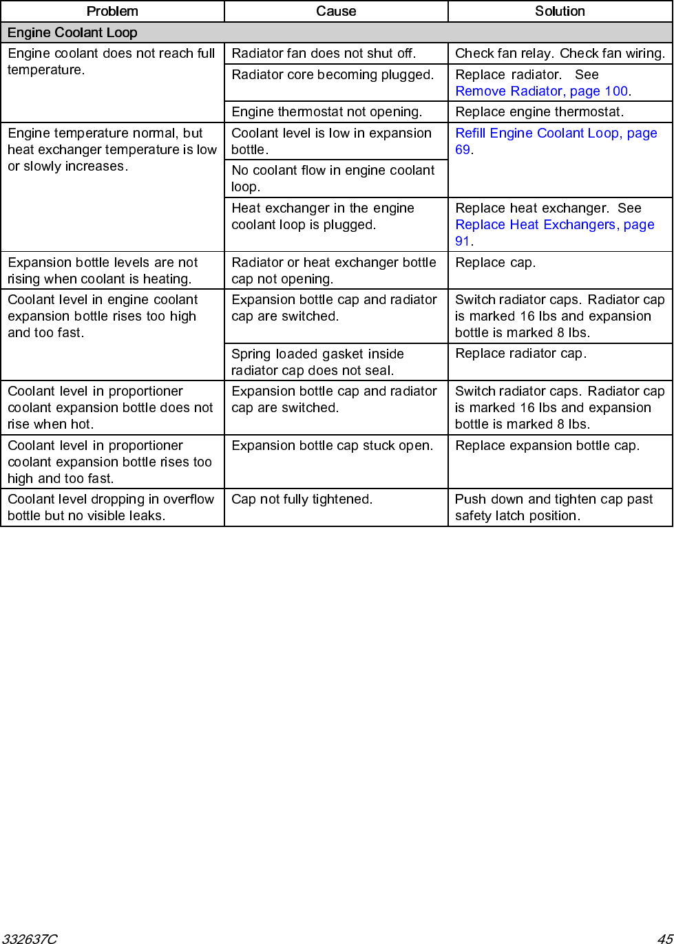
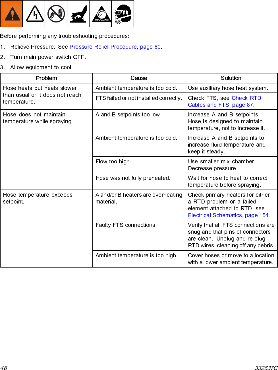
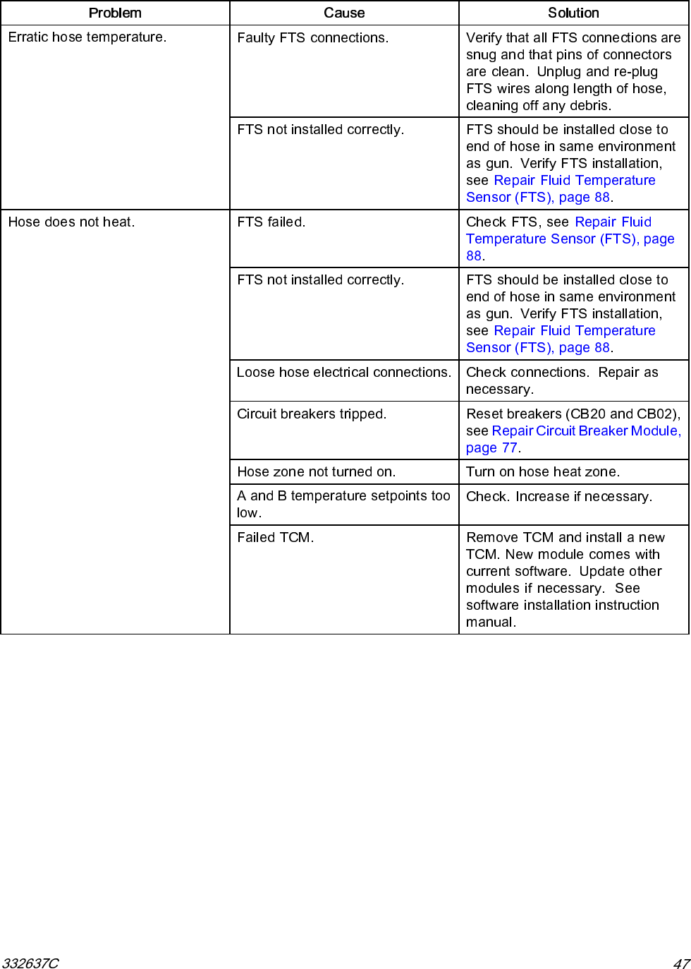
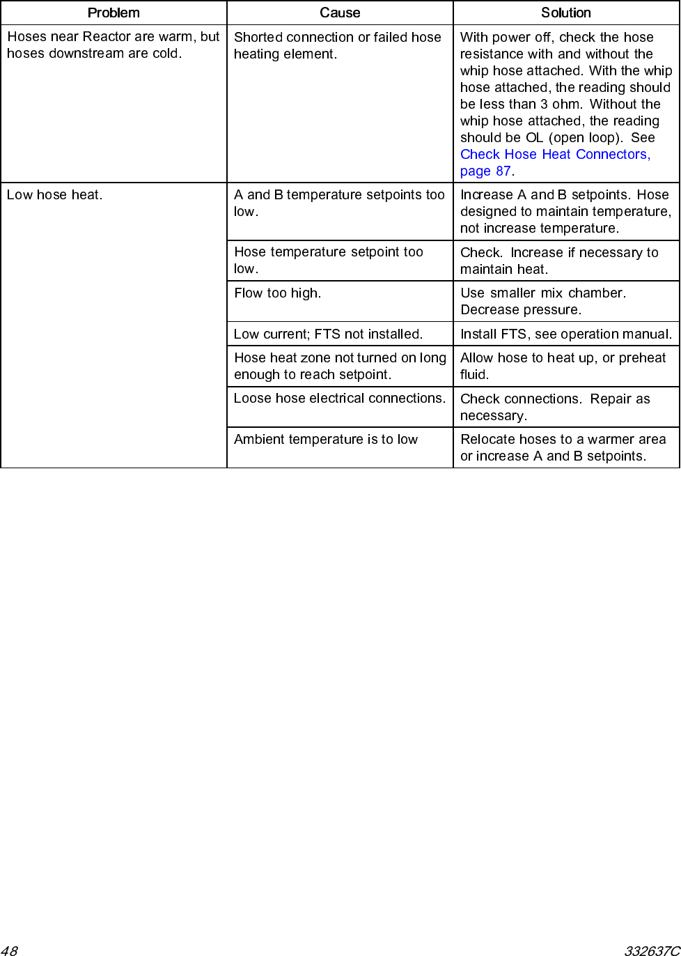
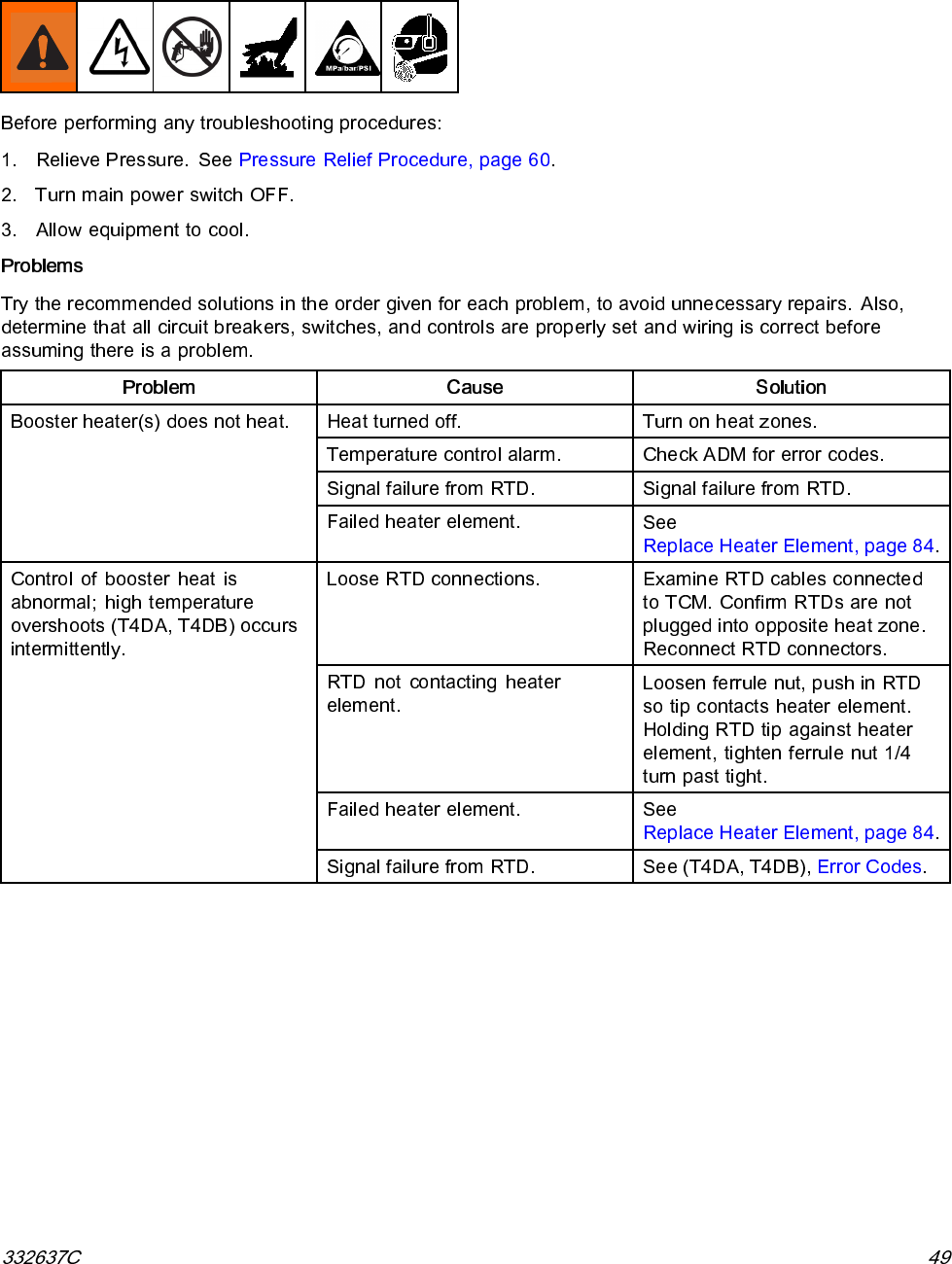
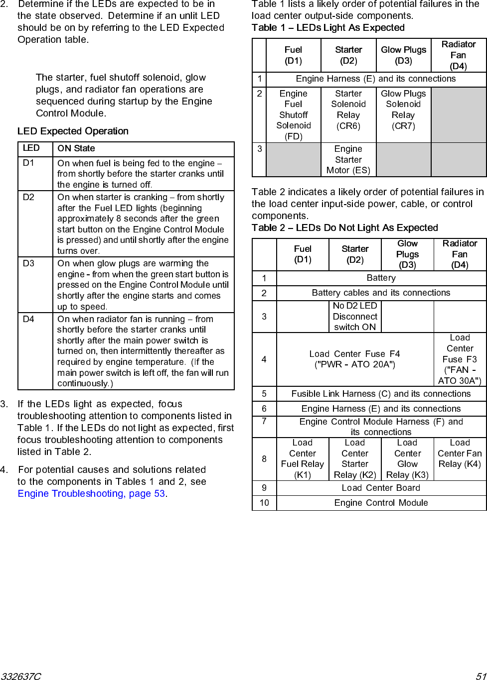
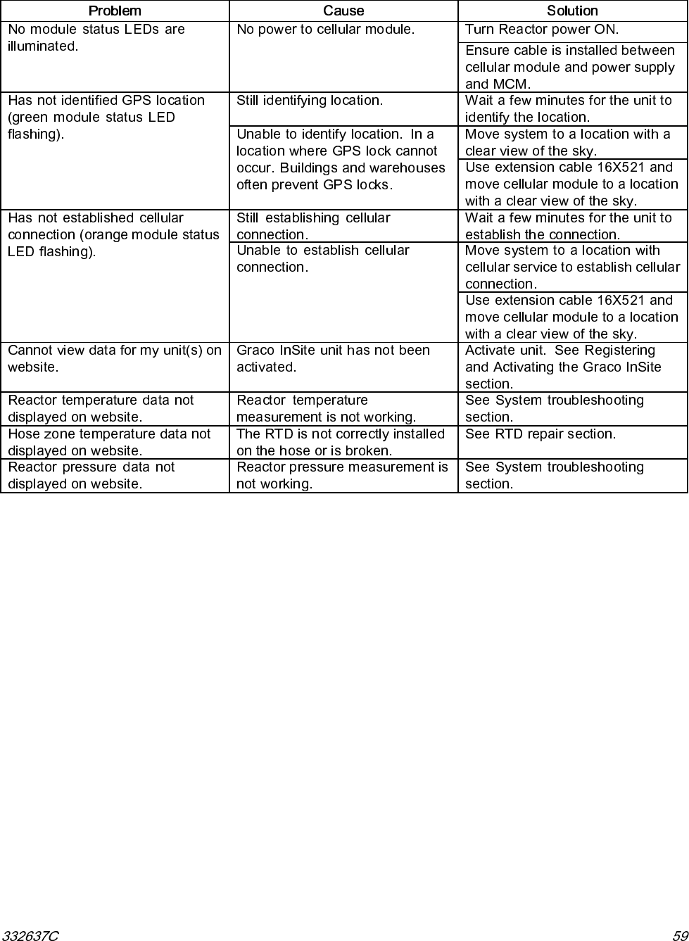
- Troubleshooting
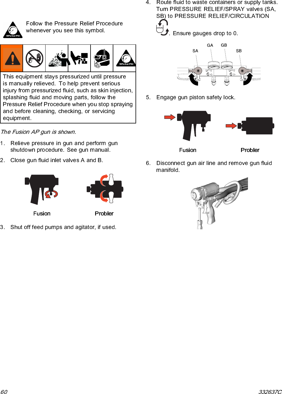
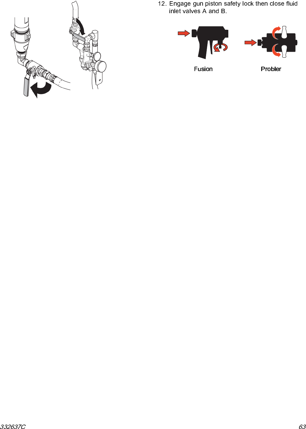
- Pressure Relief Procedure
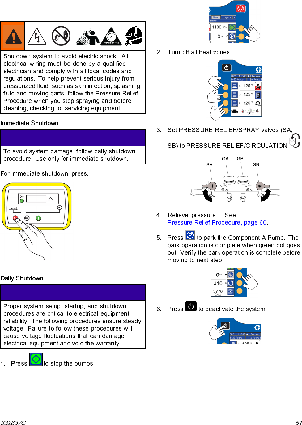
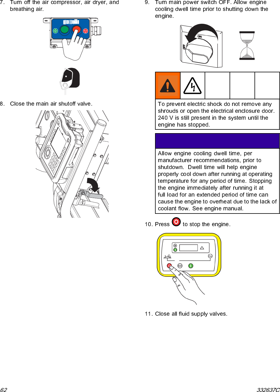
- Shutdown
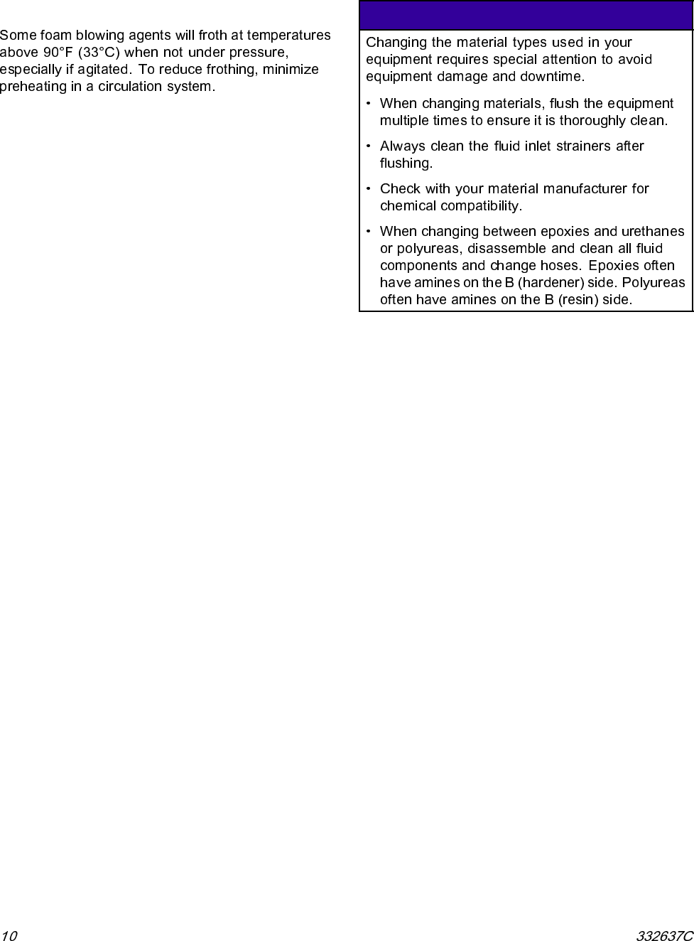
- Flushing
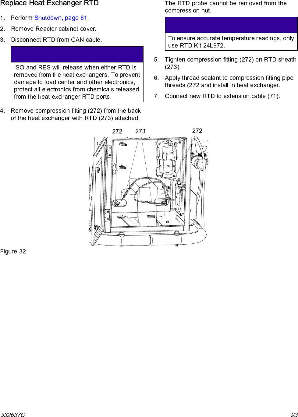
- Repair
- Before Beginning Repair
- Flush Inlet Strainer Screen
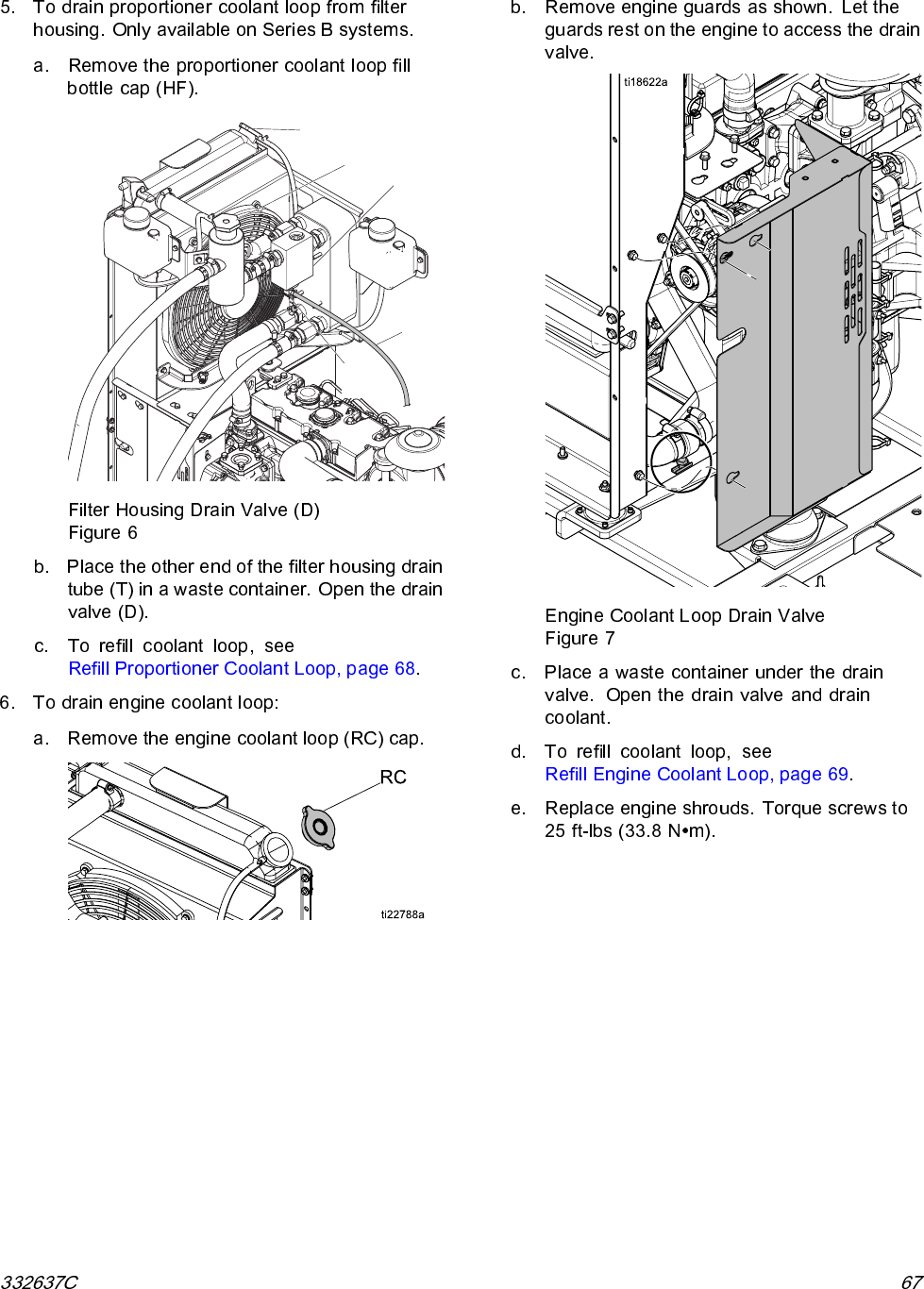
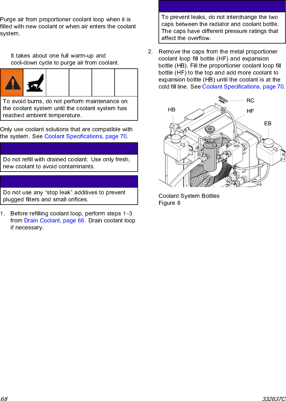
- Drain Coolant
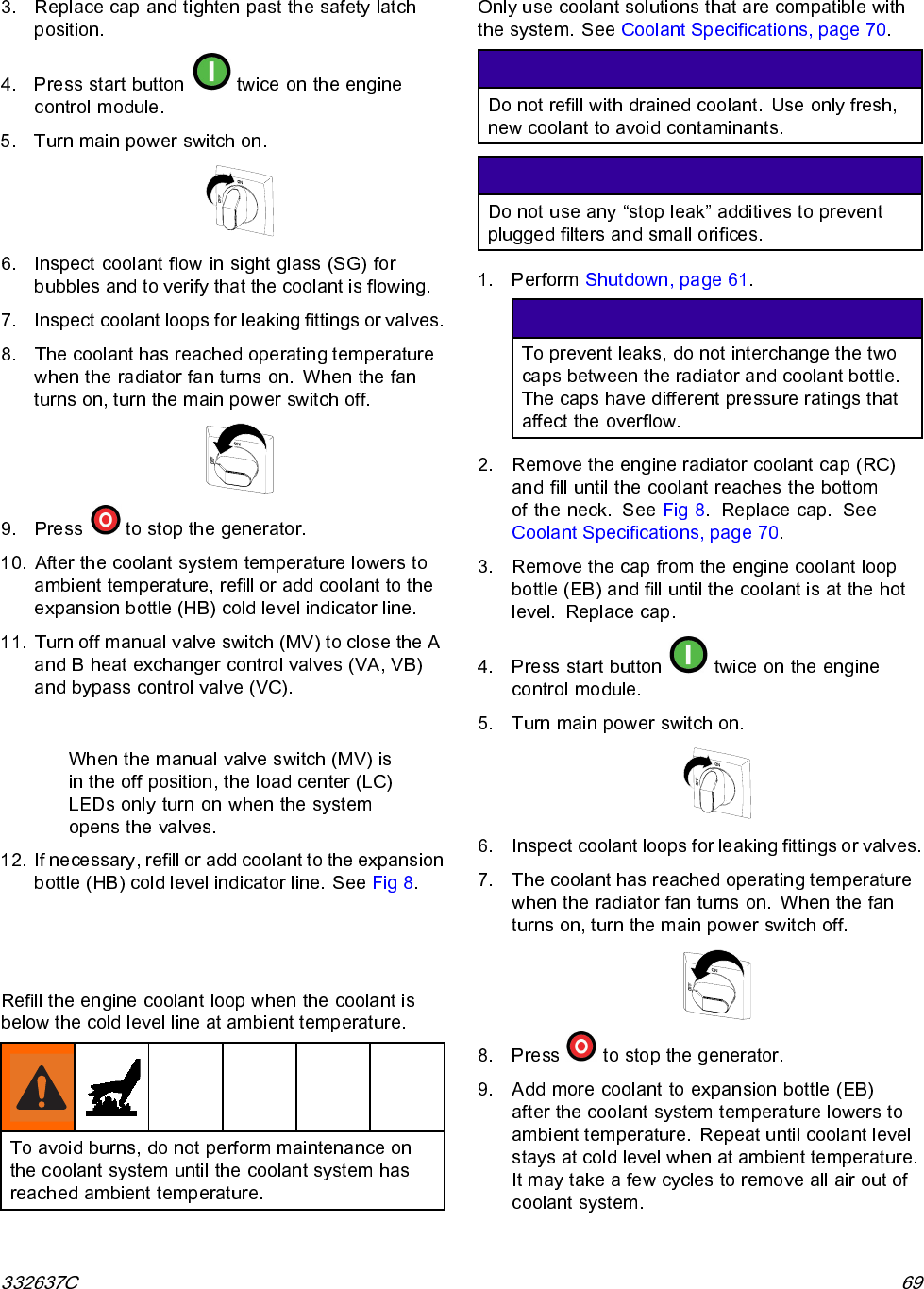
- Refill Proportioner Coolant Loop
- Refill Engine Coolant Loop
- Coolant Specifications
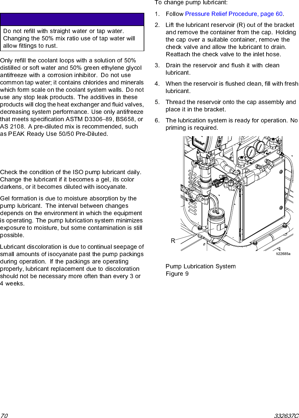
- Change Pump Lubricant
- Remove Pump
- Install Pump
- Repair Drive Housing
- Repair Electric Motor
- Repair Circuit Breaker Module
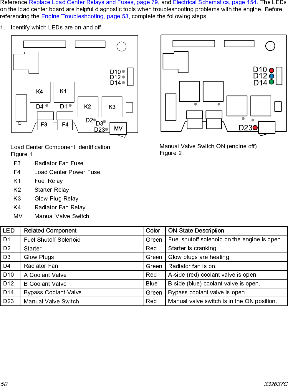
- Replace Load Center Relays and Fuses
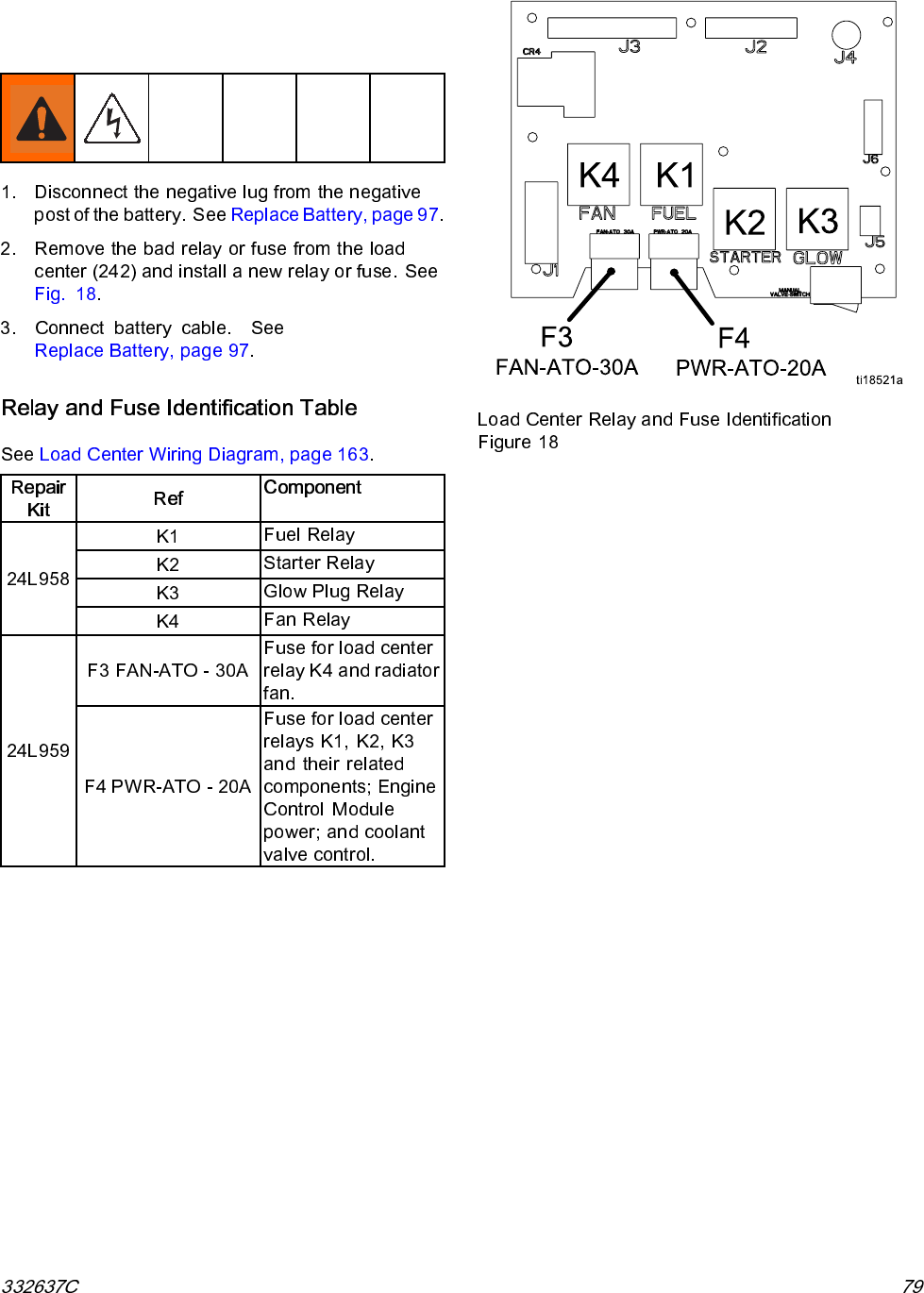
- Relay and Fuse Identification Table
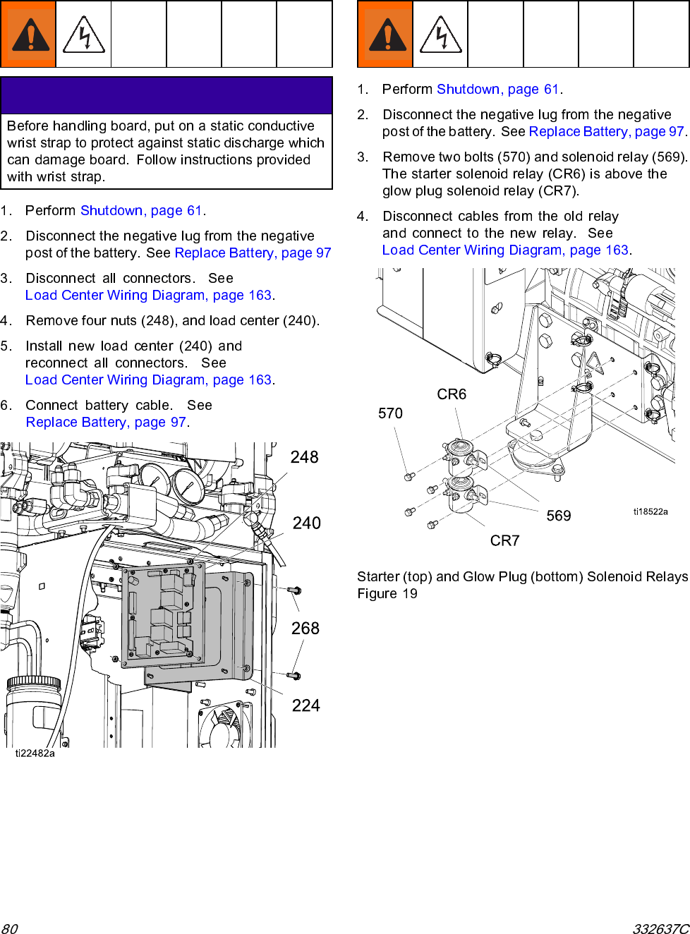
- Replace Load Center
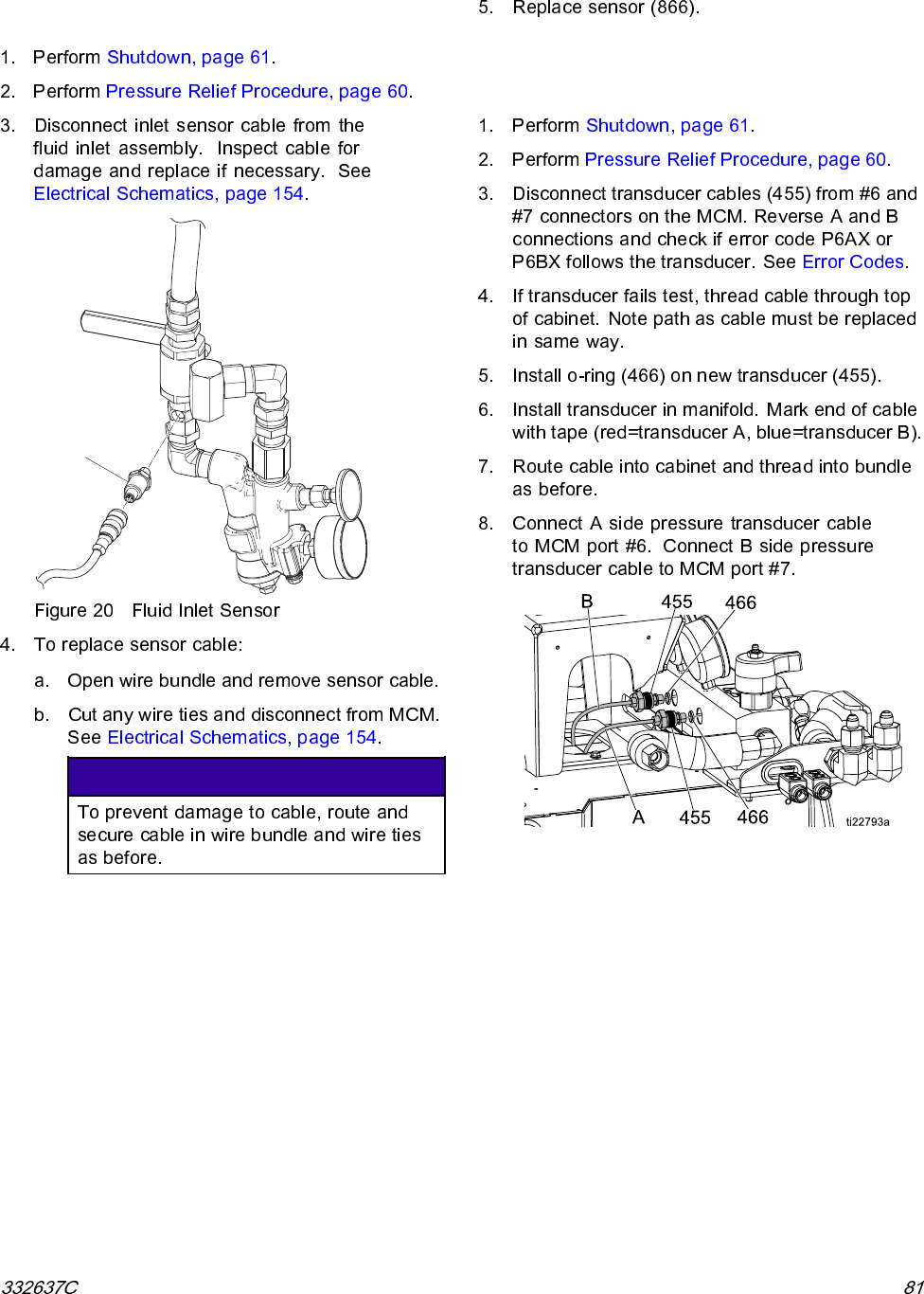
- Replace Engine Solenoid Relays
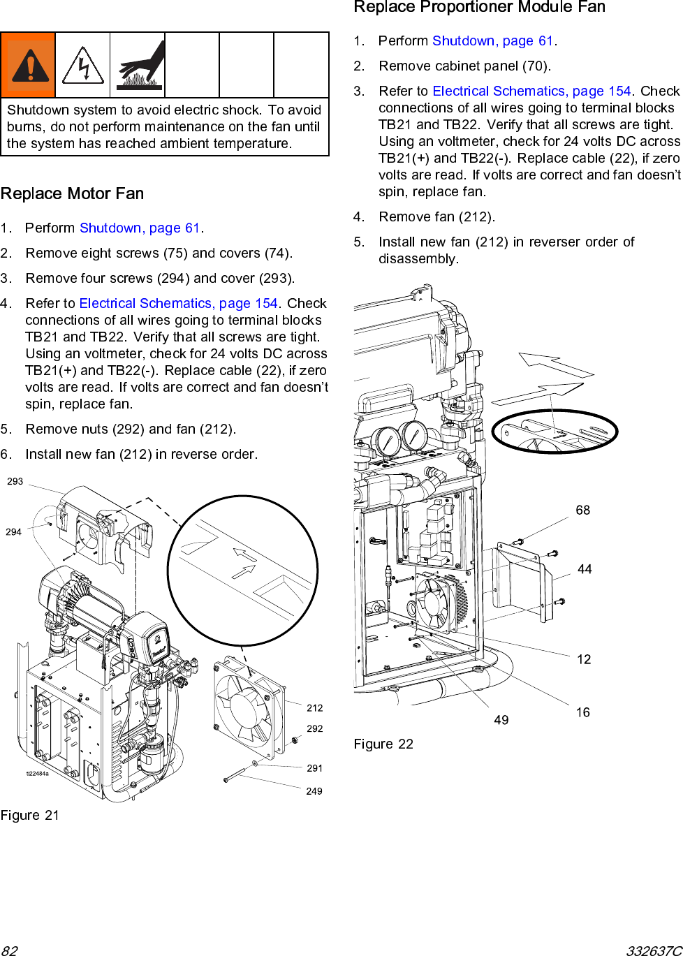
- Replace Fluid Inlet Sensor
- Replace Pressure Transducers
- Replace Fans
- Repair Booster Heater
- Repair Heated Hose
- Repair Fluid Temperature Sensor (FTS)
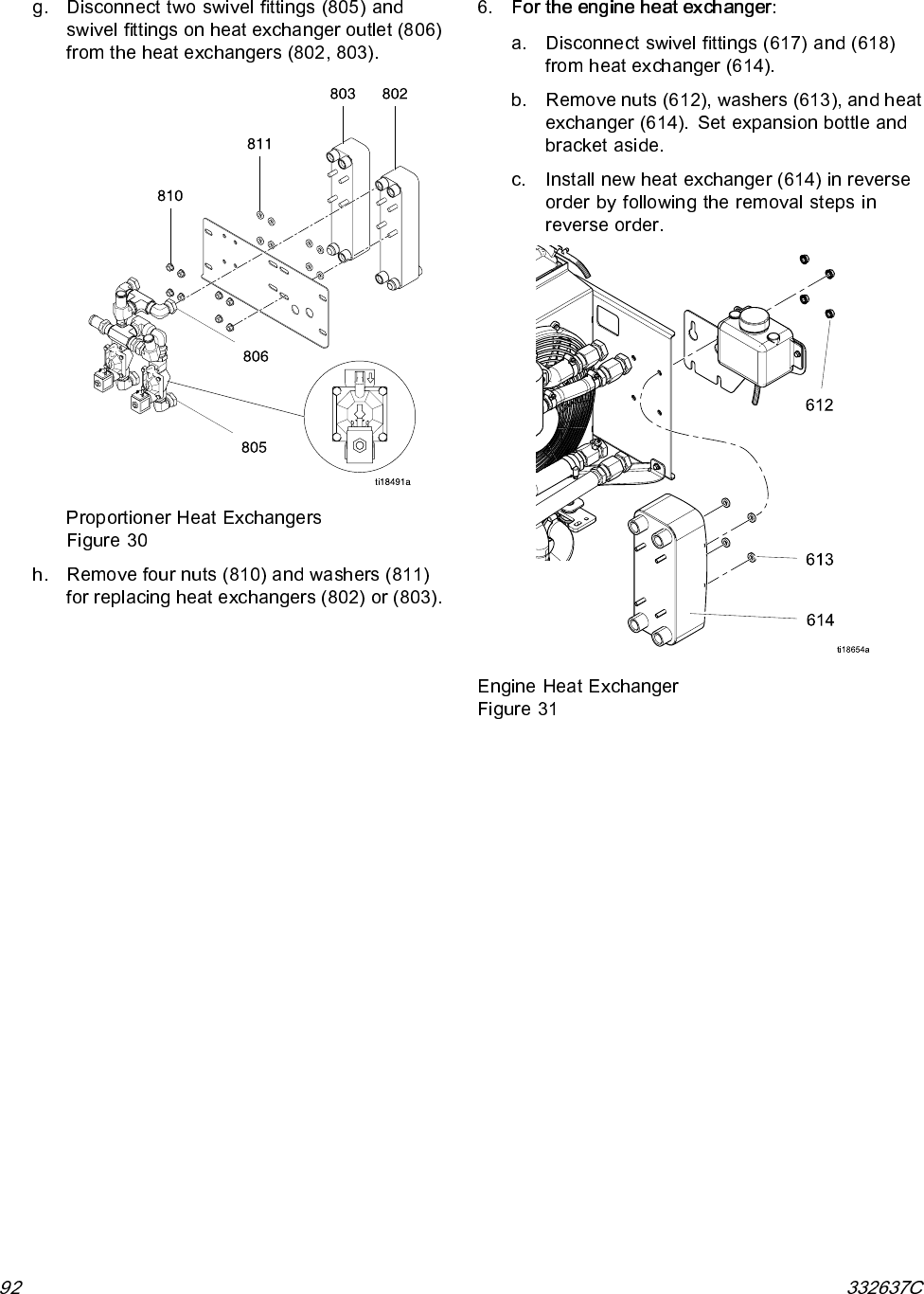
- Replace Heat Exchangers
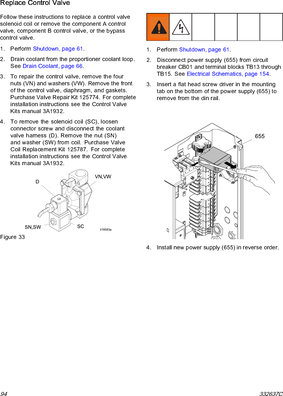
- Replace Power Supply
- Replace Circulation Pump
- Repair Filter Housing Filter
- Remove Fuel Tank
- Replace Battery
- Repair Fusible Link Harness
- Remove Radiator
- Replace Advanced Display Module (ADM)
- Replace Engine Control Module
- Replace Motor Control Module (MCM)
- Replace Temperature Control Module (TCM)
- Remove Proportioner
- Repair Engine
- 12V Charge Alternator
- Notes
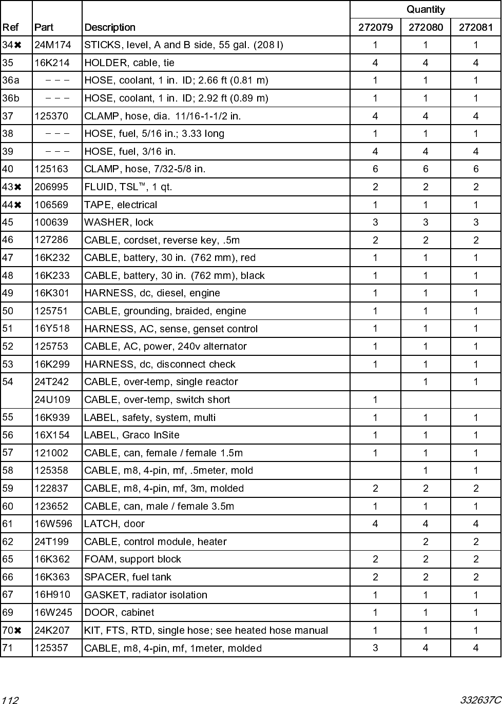
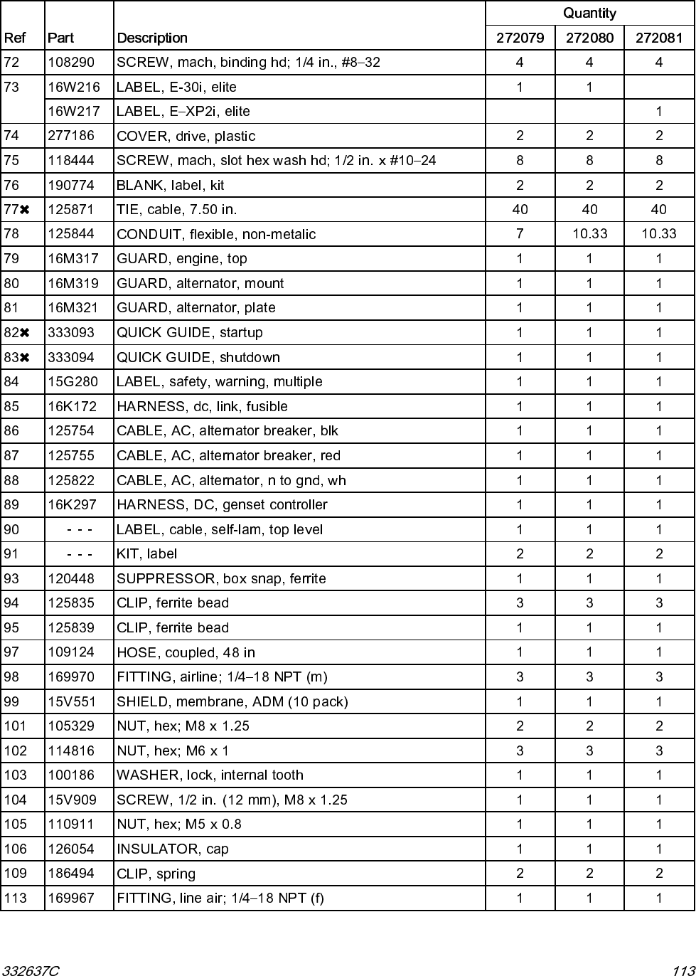
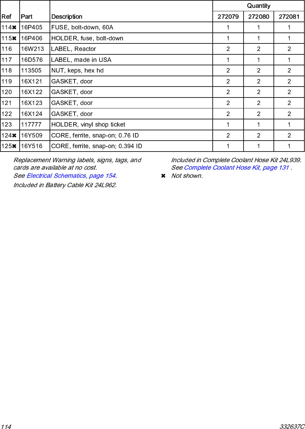
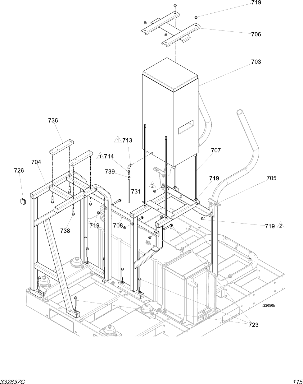
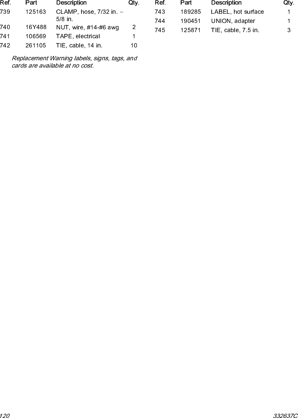
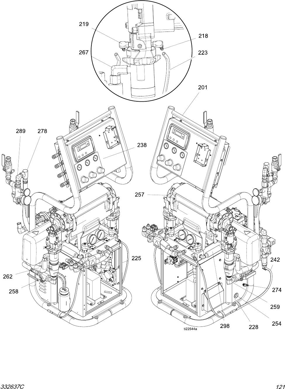
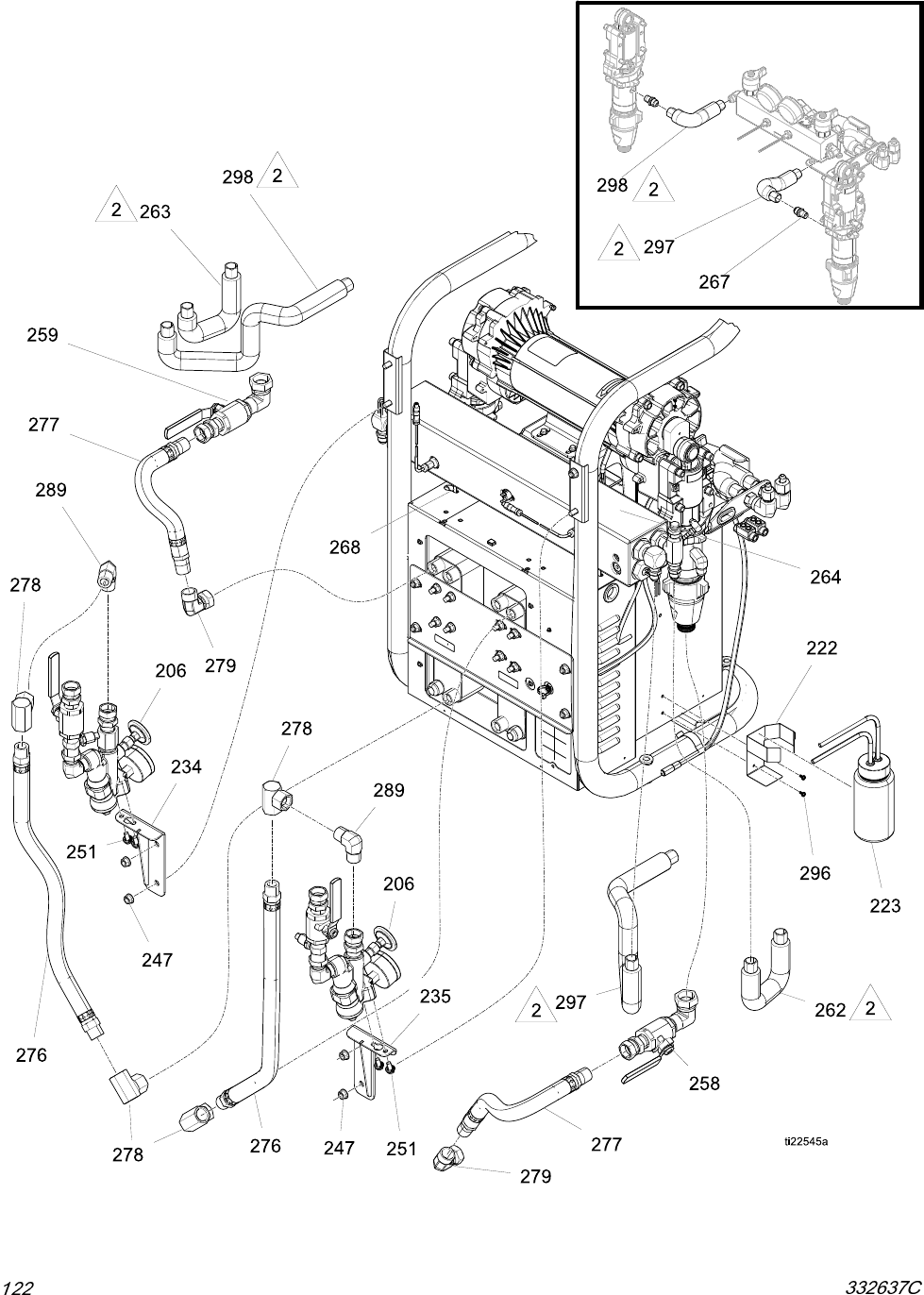
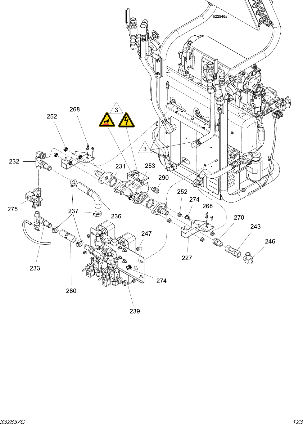
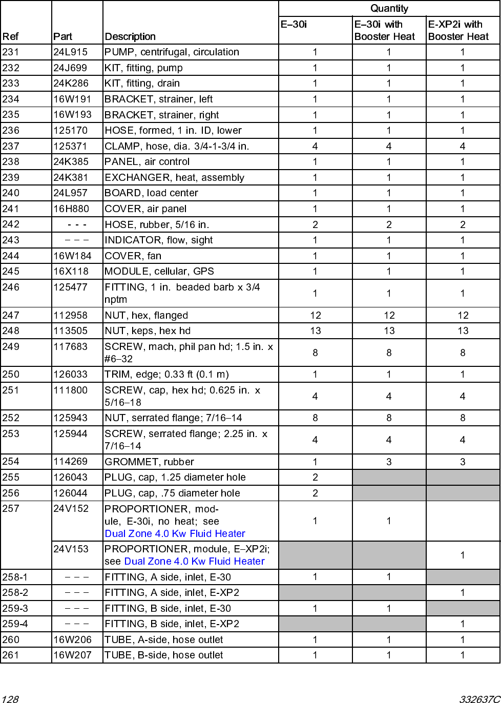
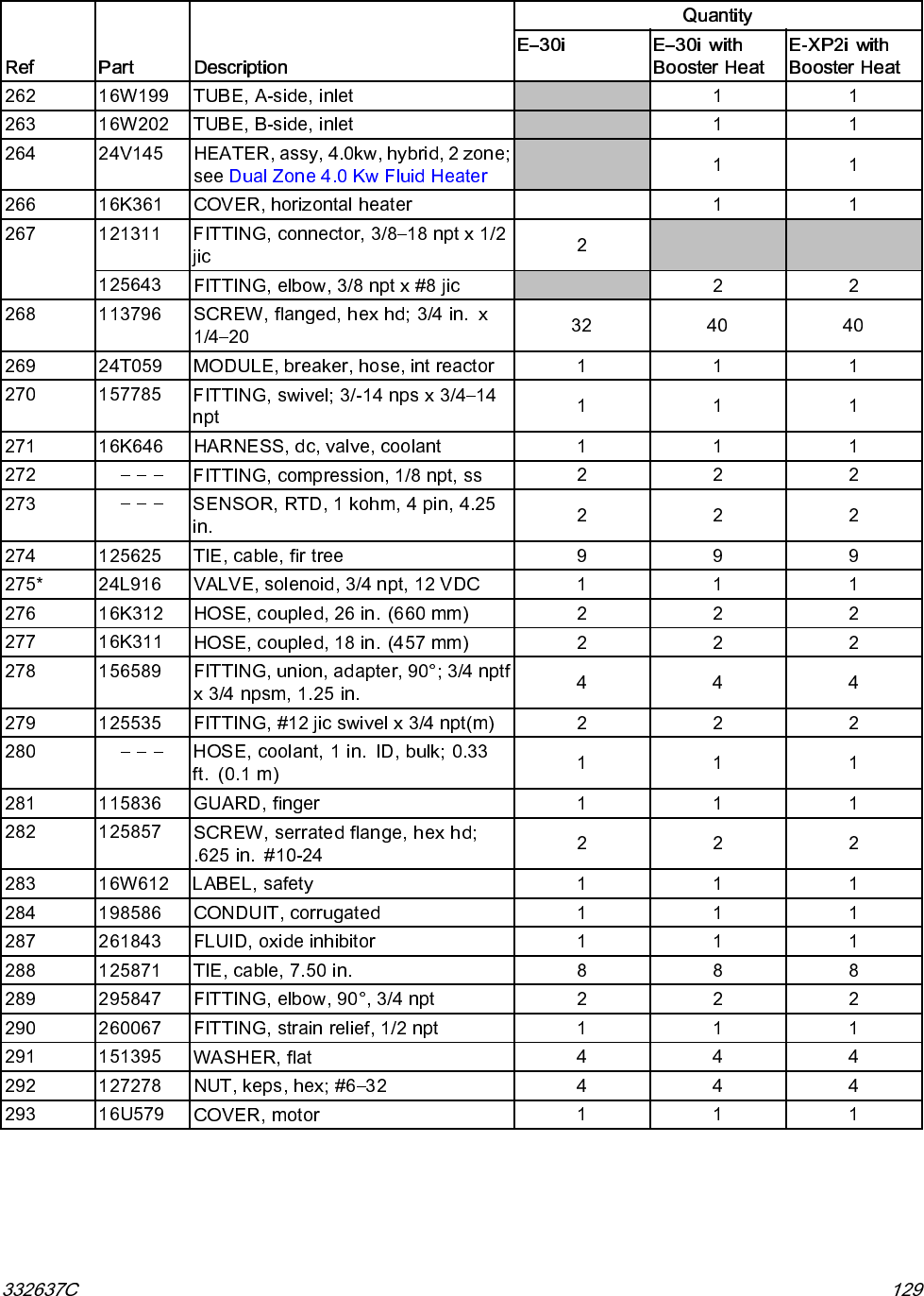
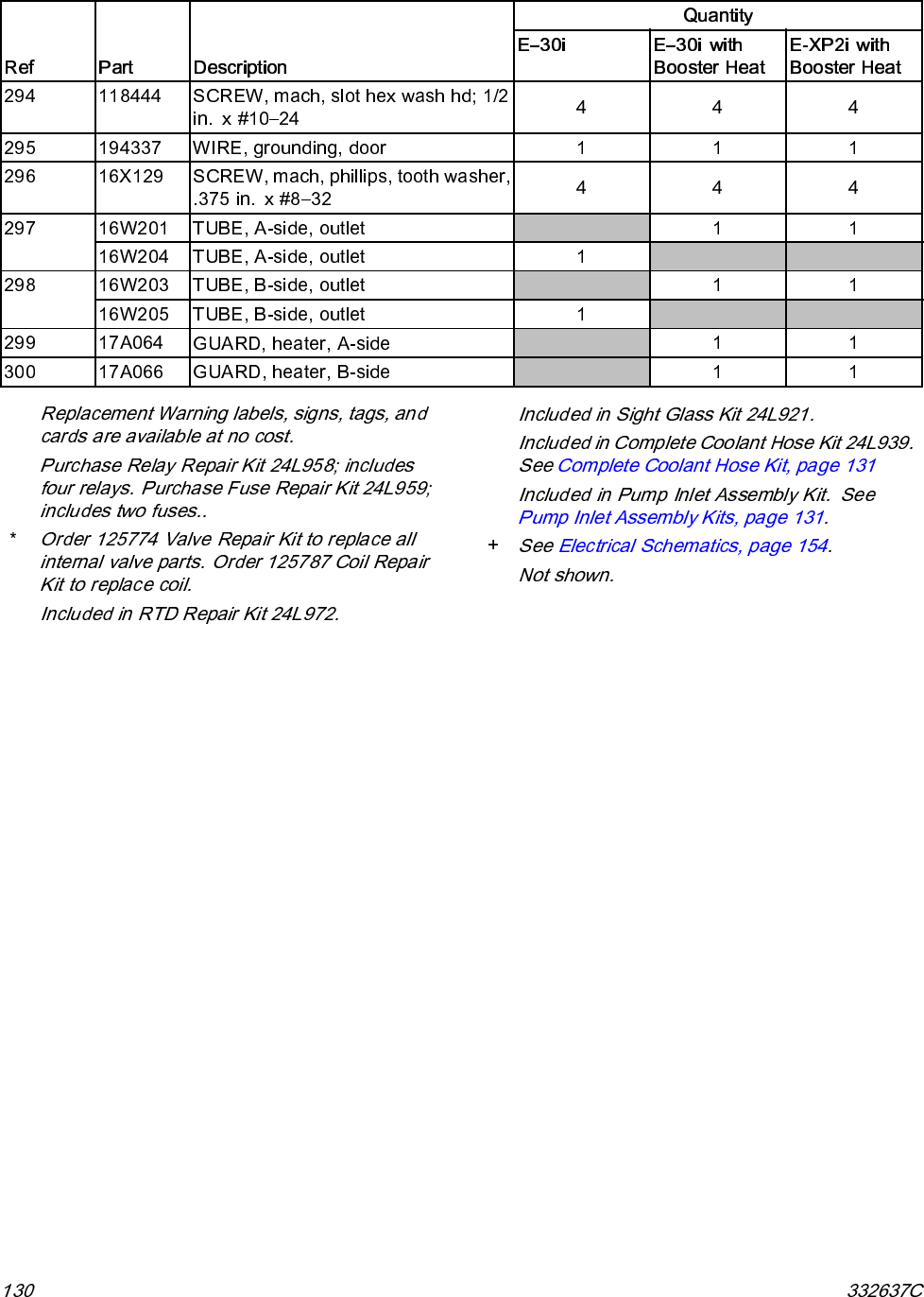
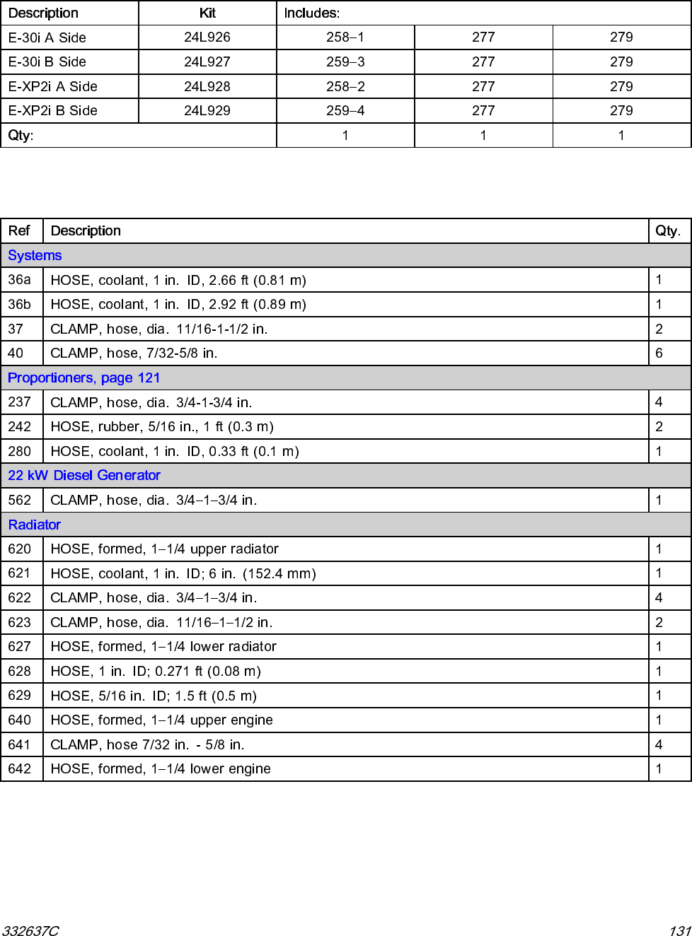
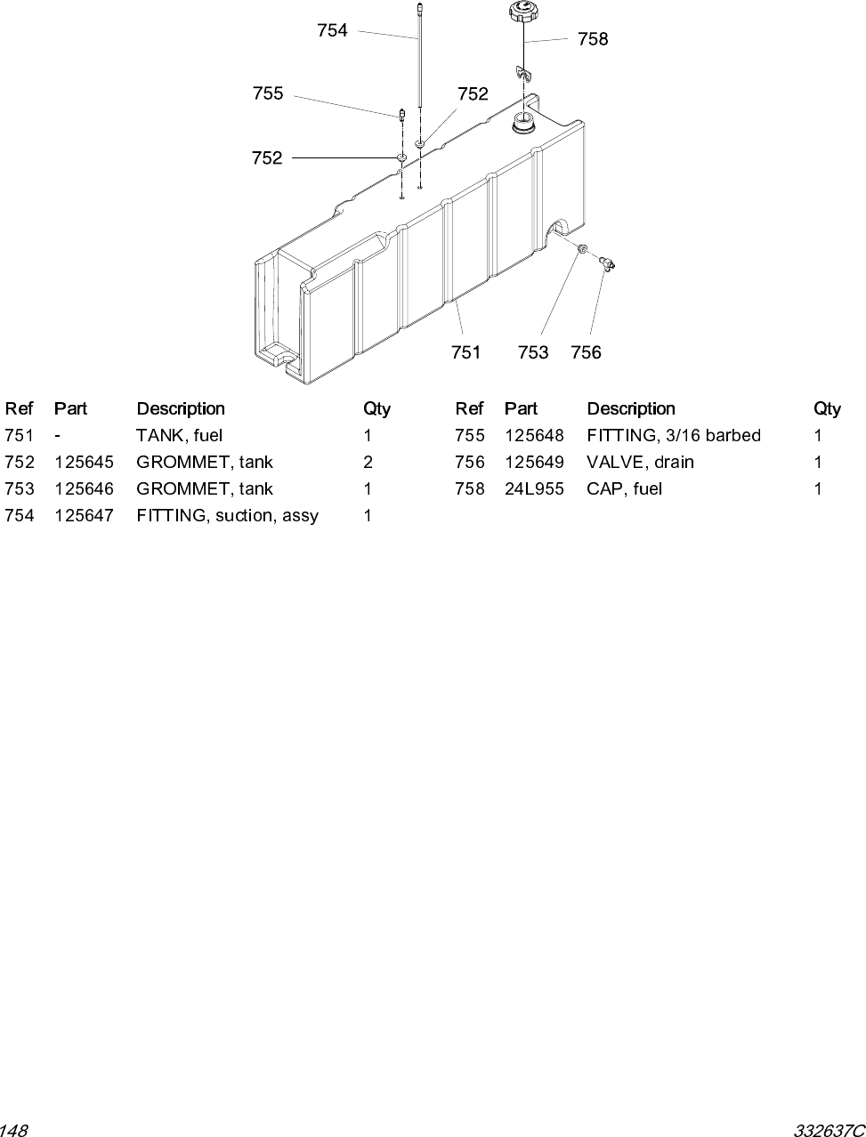
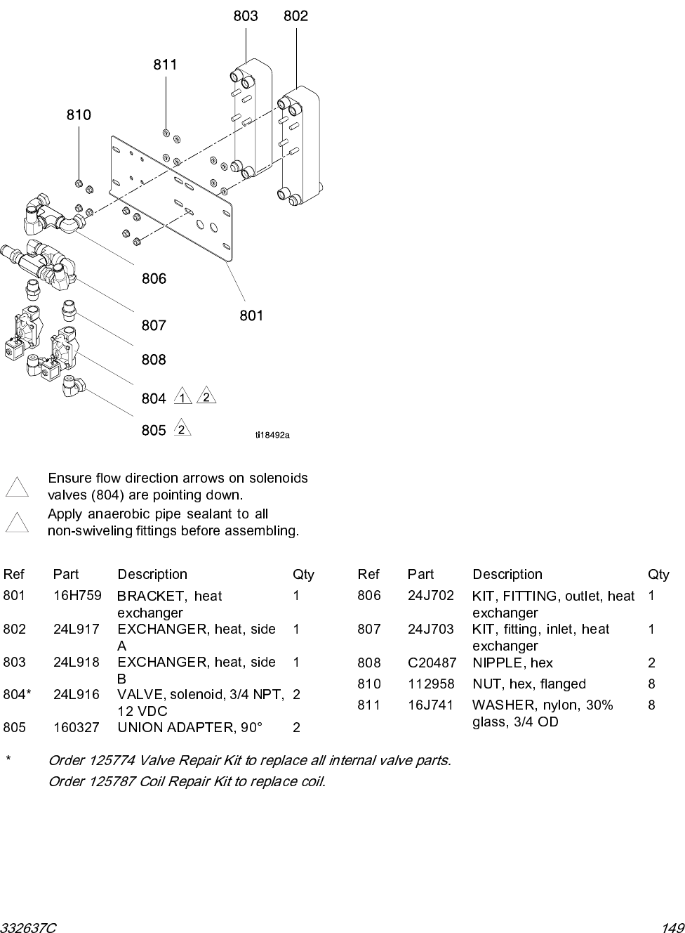
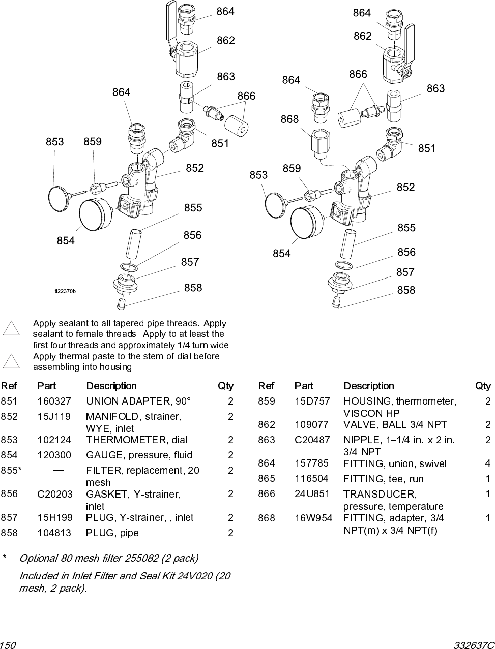
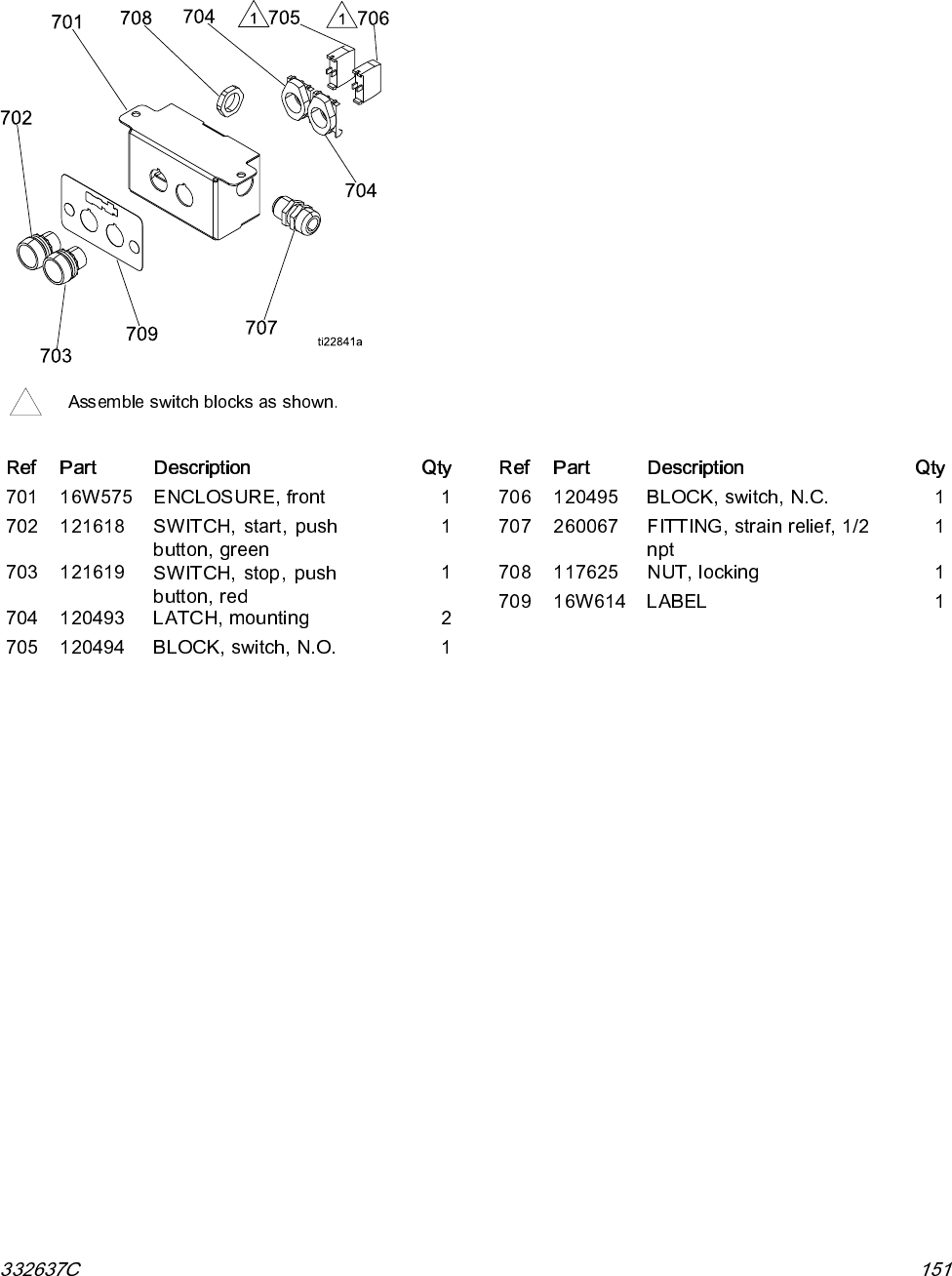
- Parts
- Electrical Schematics
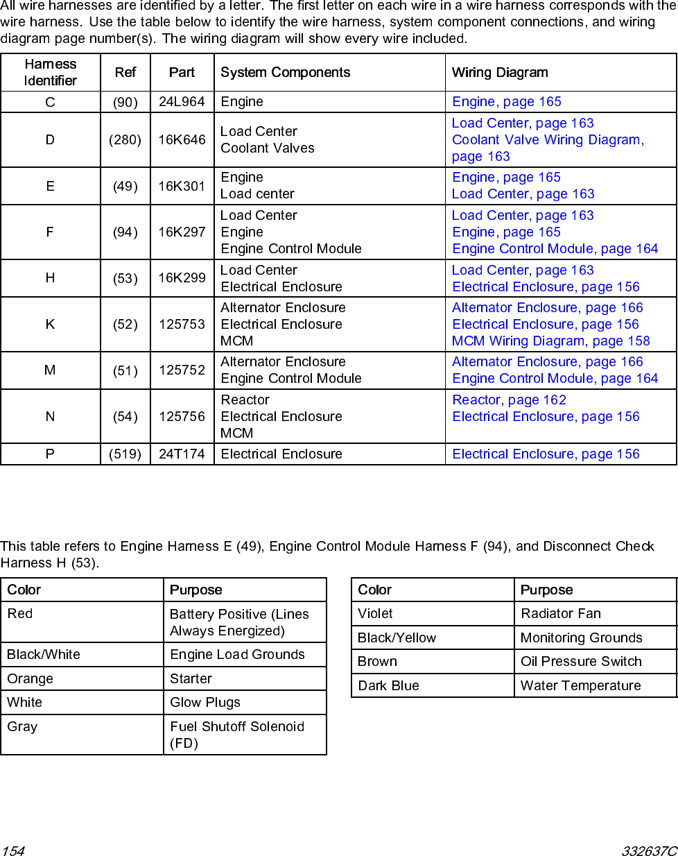
- Harness Identification
- Engine Harness Wire Color Code
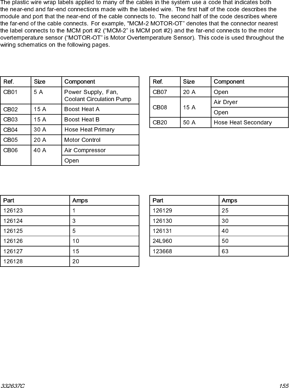
- Wire Label Identification Code
- Circuit Breaker Identification
- Available Circuit Breakers
- Electrical Enclosure Wiring Diagram
- MCM Cable Routing
- MCM Wiring Diagram
- Booster Heater Wiring Diagram
- Optional Remote Display Module and Feed Pump Kit Wiring Diagram
- Optional Customer Auxiliary Power Wiring Diagram
- Reactor Cabinet Wiring Diagram
- Load Center Wiring Diagram
- Coolant Valve (12 VDC) Wiring Diagram
- Engine Control Module Wiring Diagram
- Engine Wiring Diagram
- Alternator Enclosure Wiring Diagram
- Air Compressor Wiring Diagram
- Air Compressor Junction Boxes
- Motor Starter
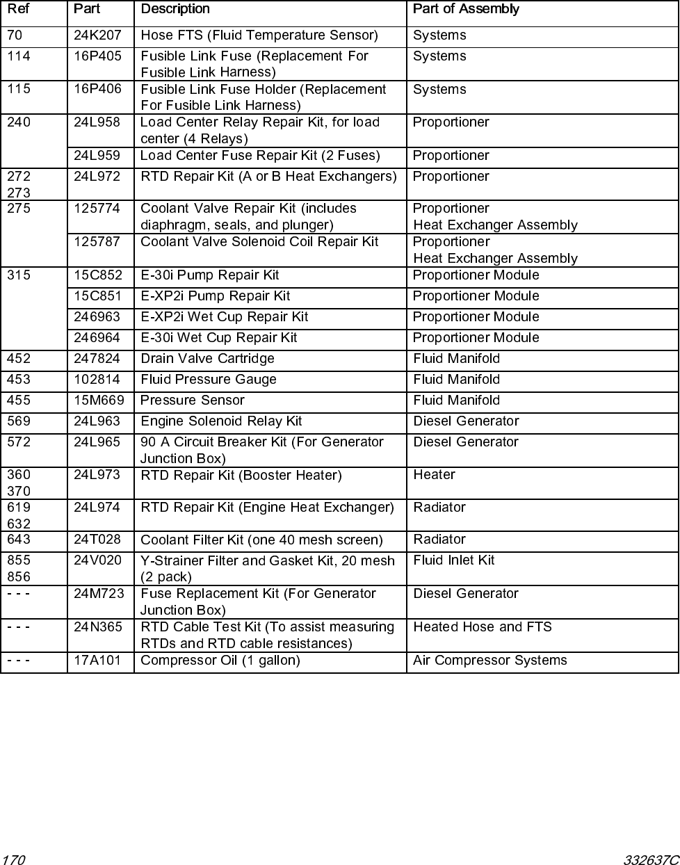
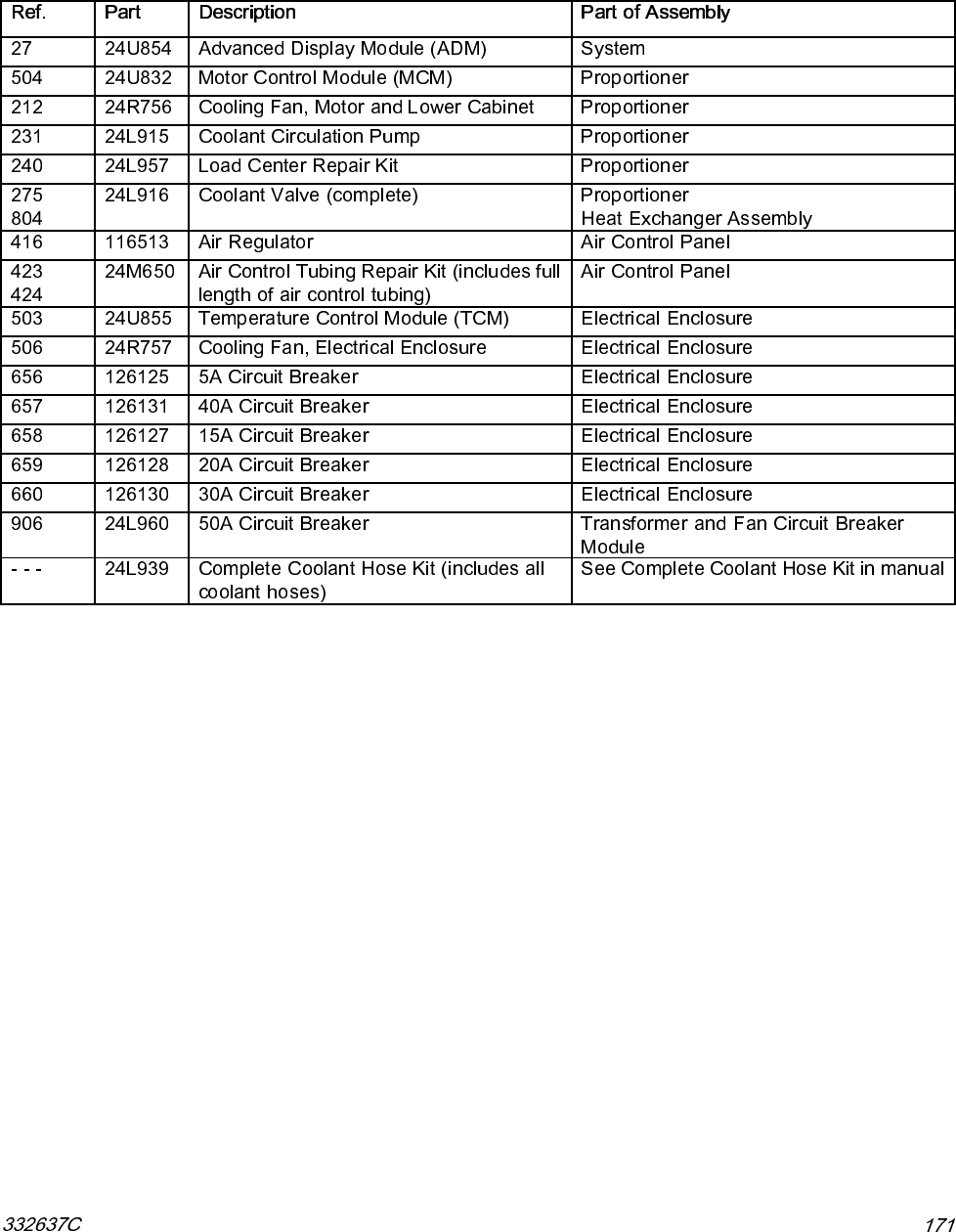
- Repair and Spare Parts Reference
- Recommended Rebuild Spare Parts
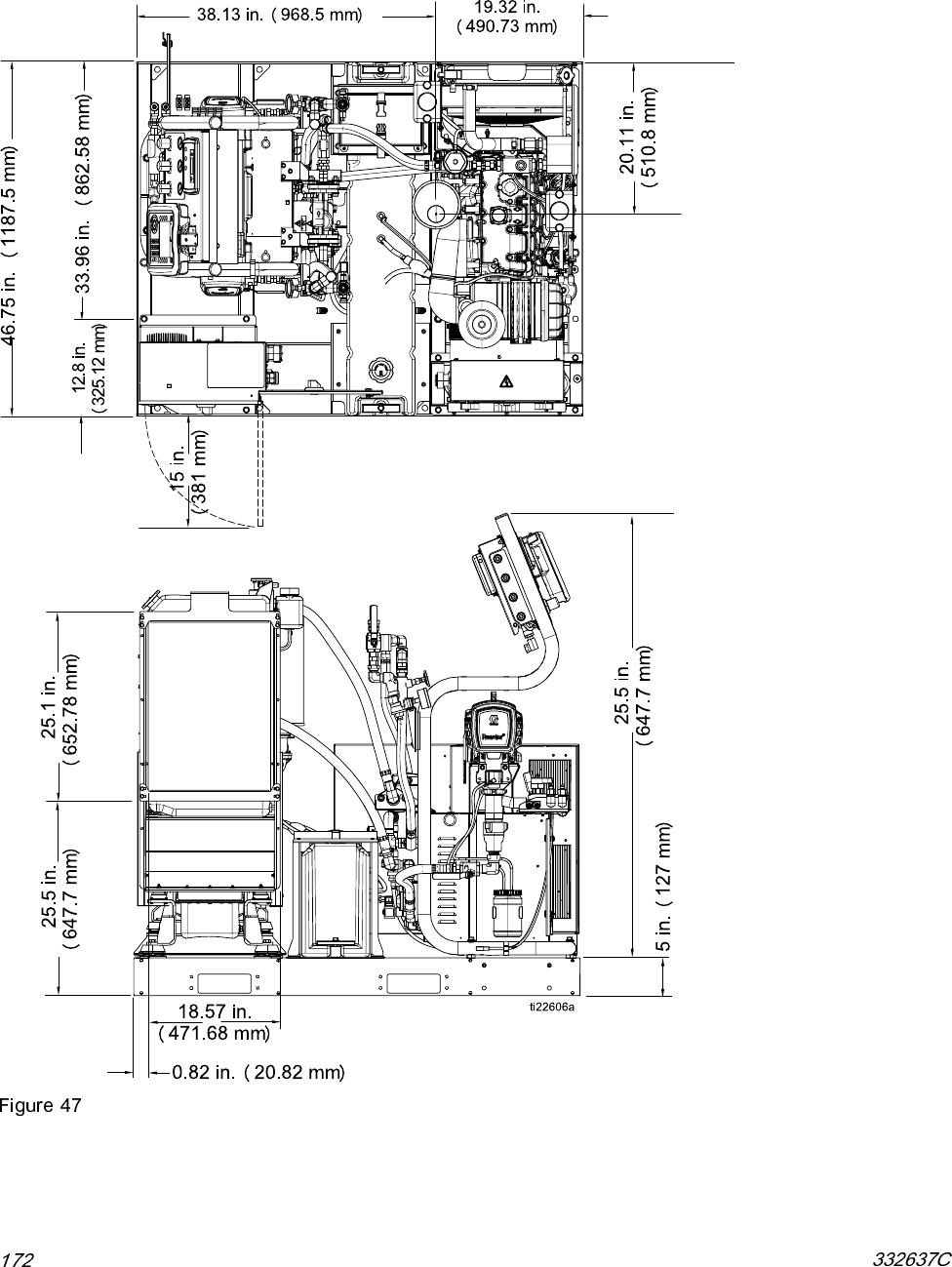
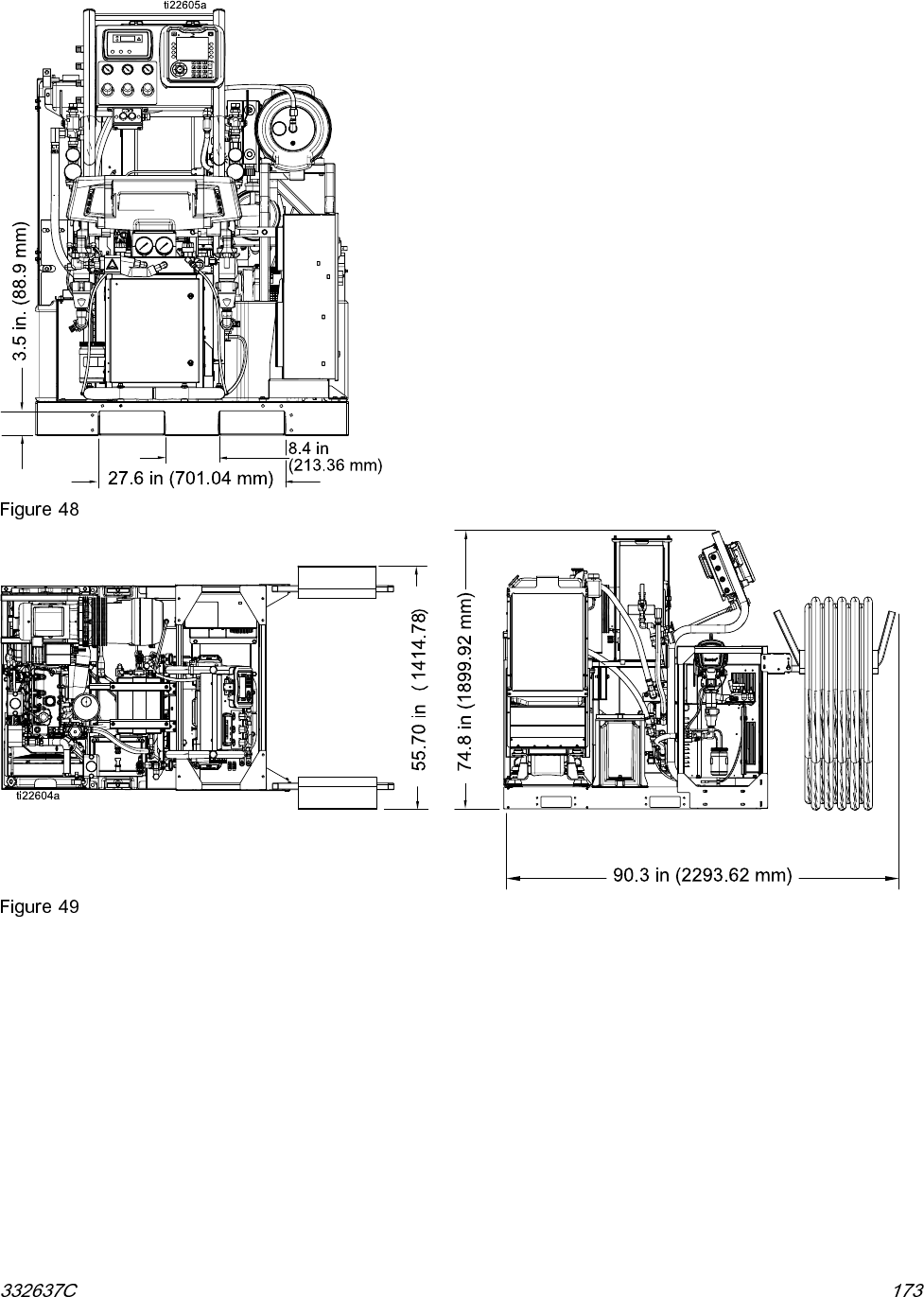
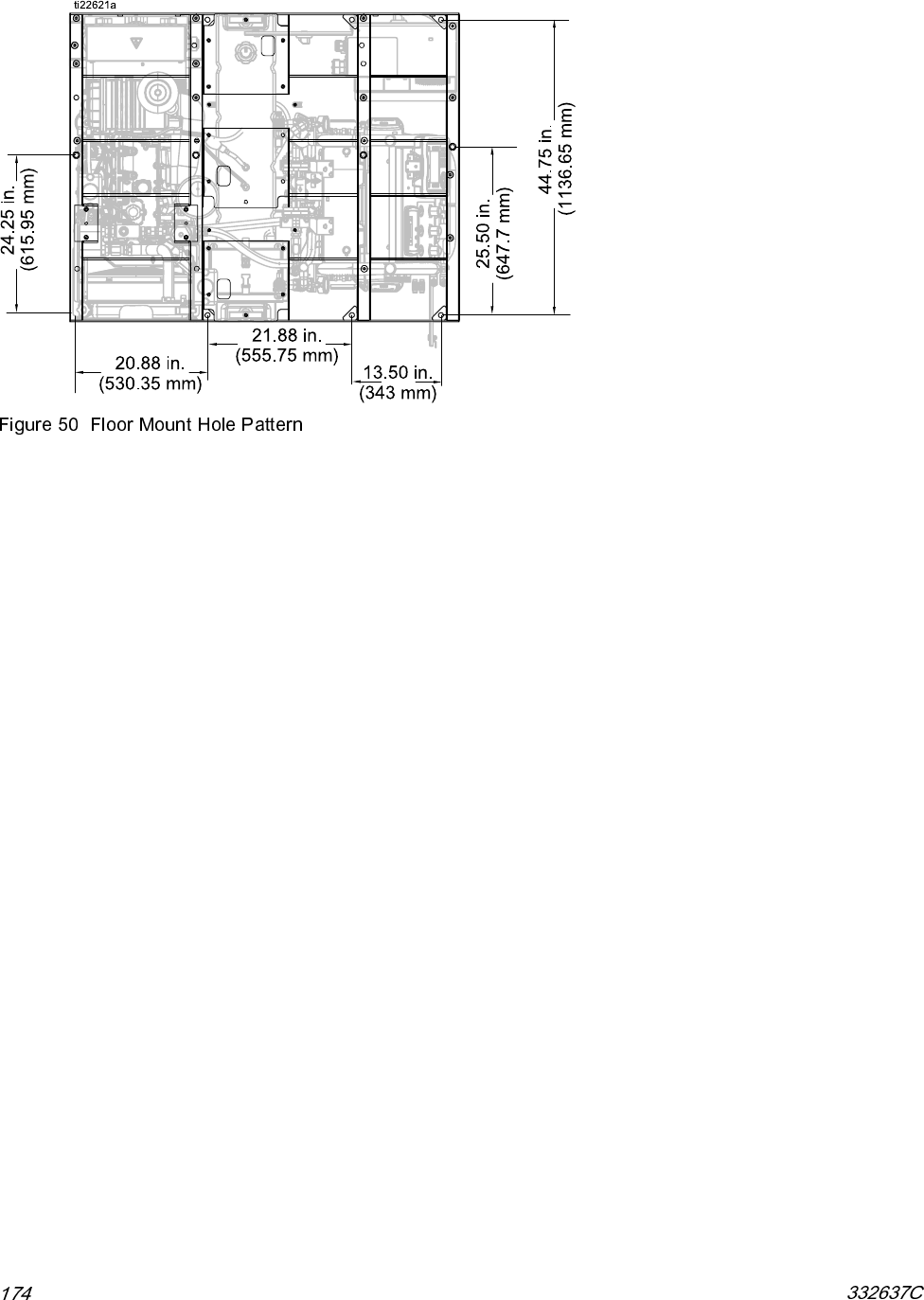
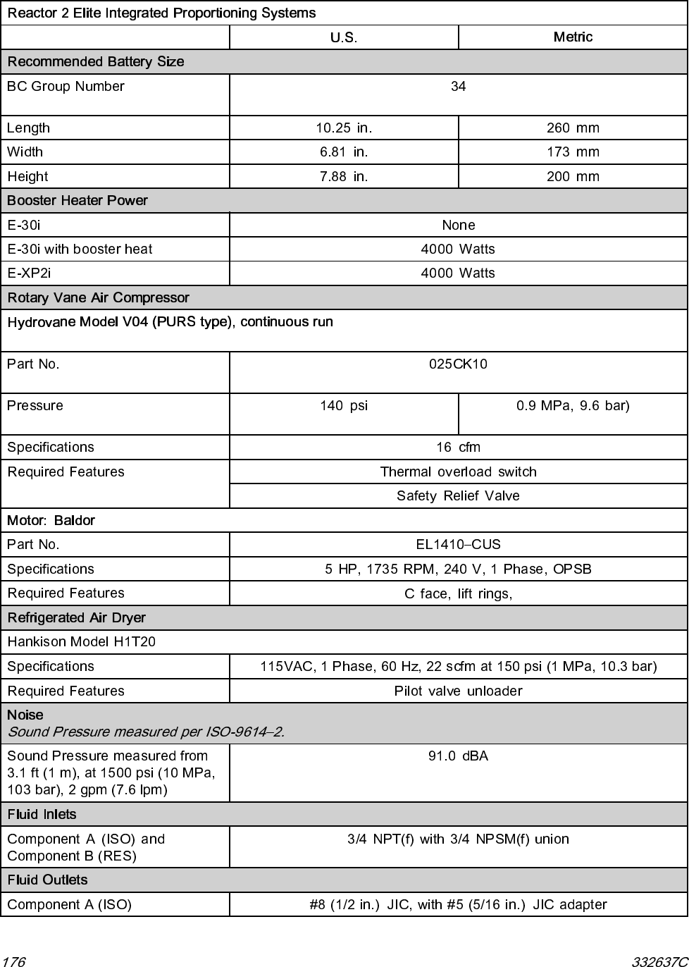
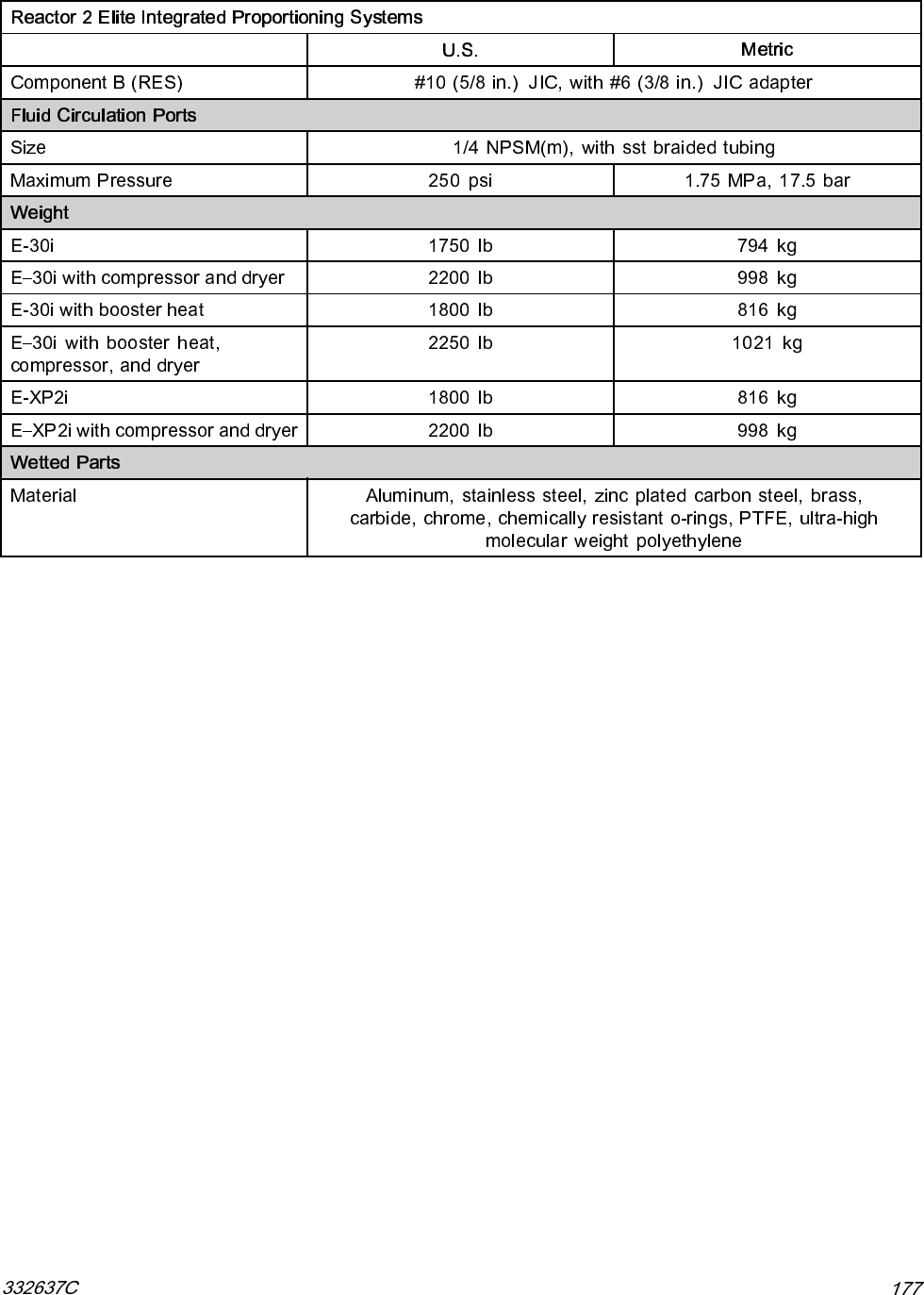
- Dimensions
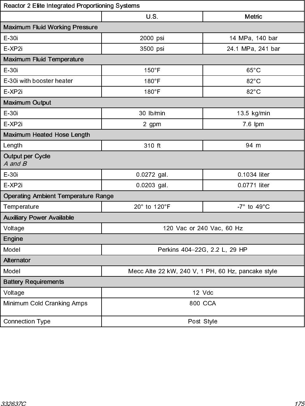
- Technical Specifications
- Notes
- Graco Extended Warranty for Integrated Reactor® 2 Components
- Contents
- tables
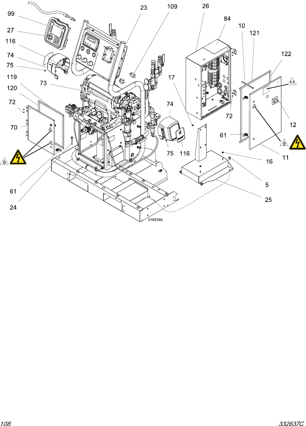
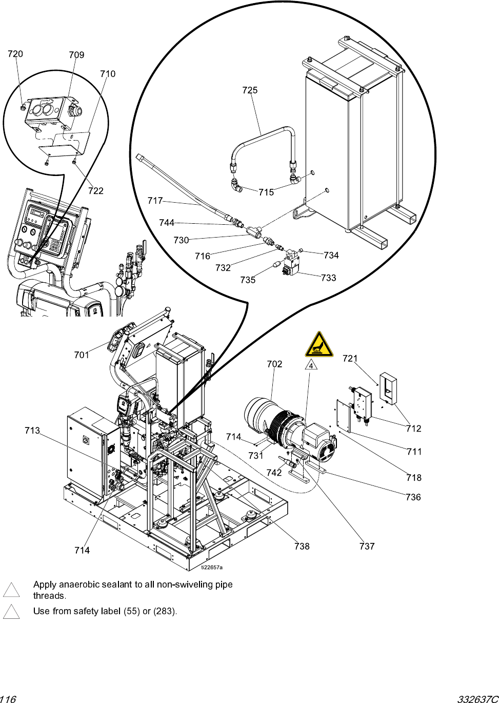
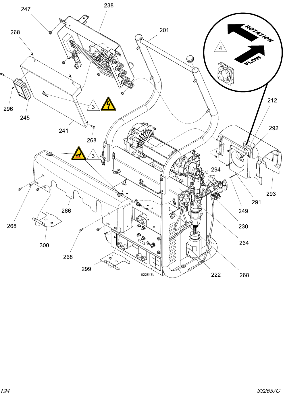
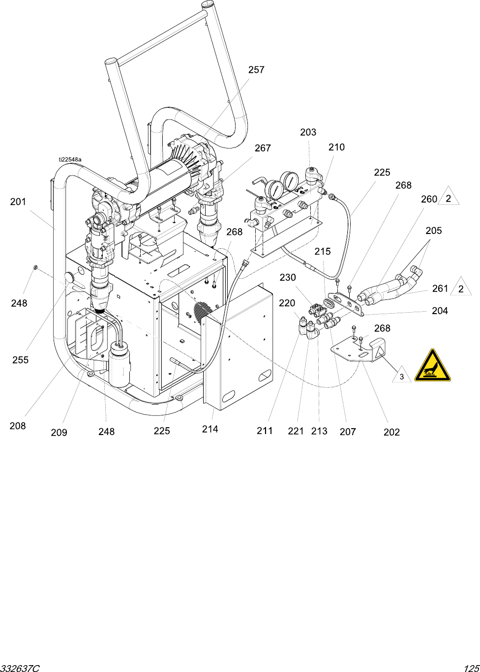
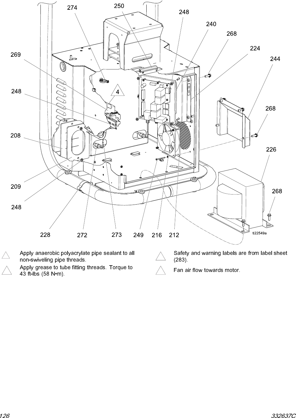
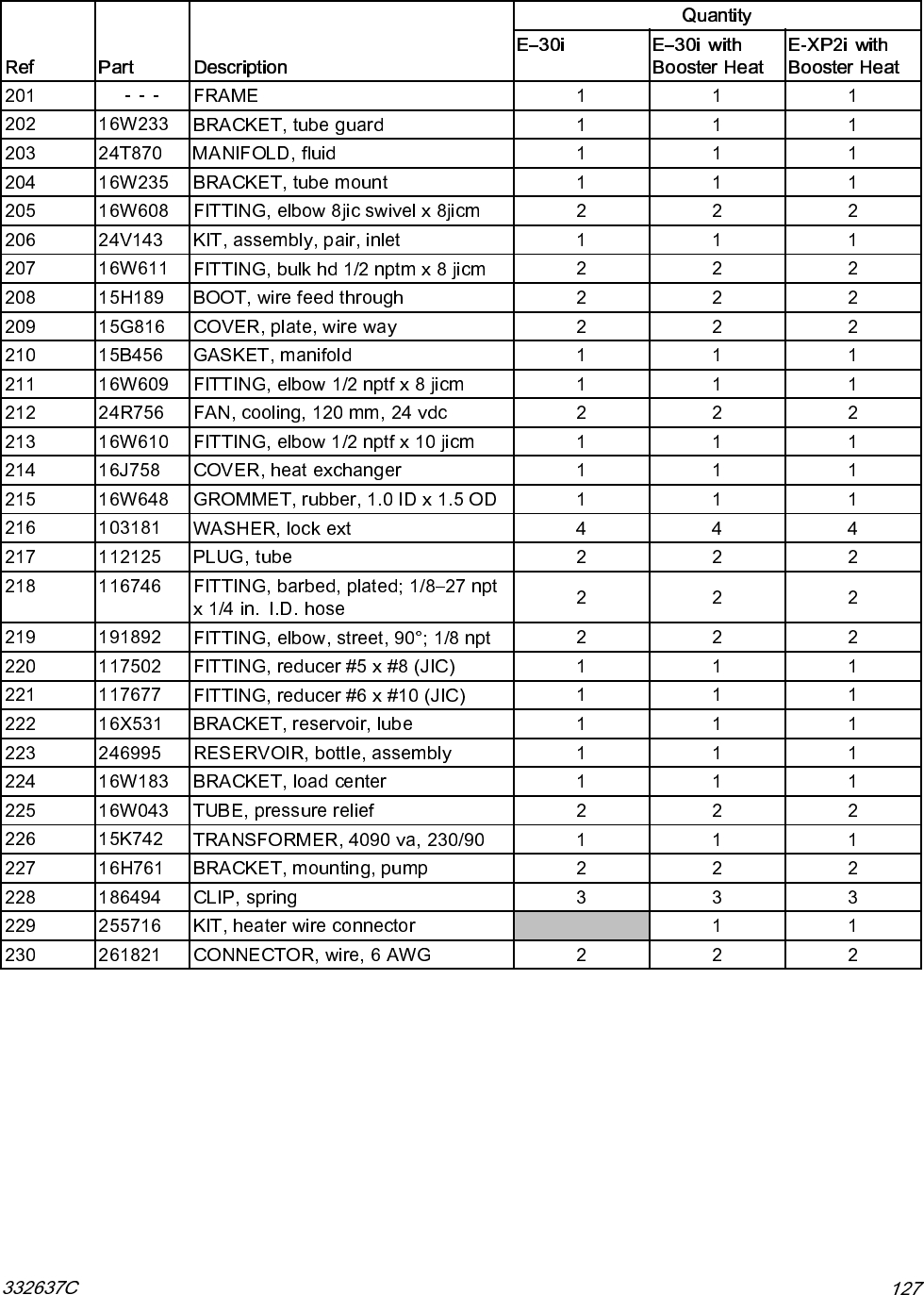
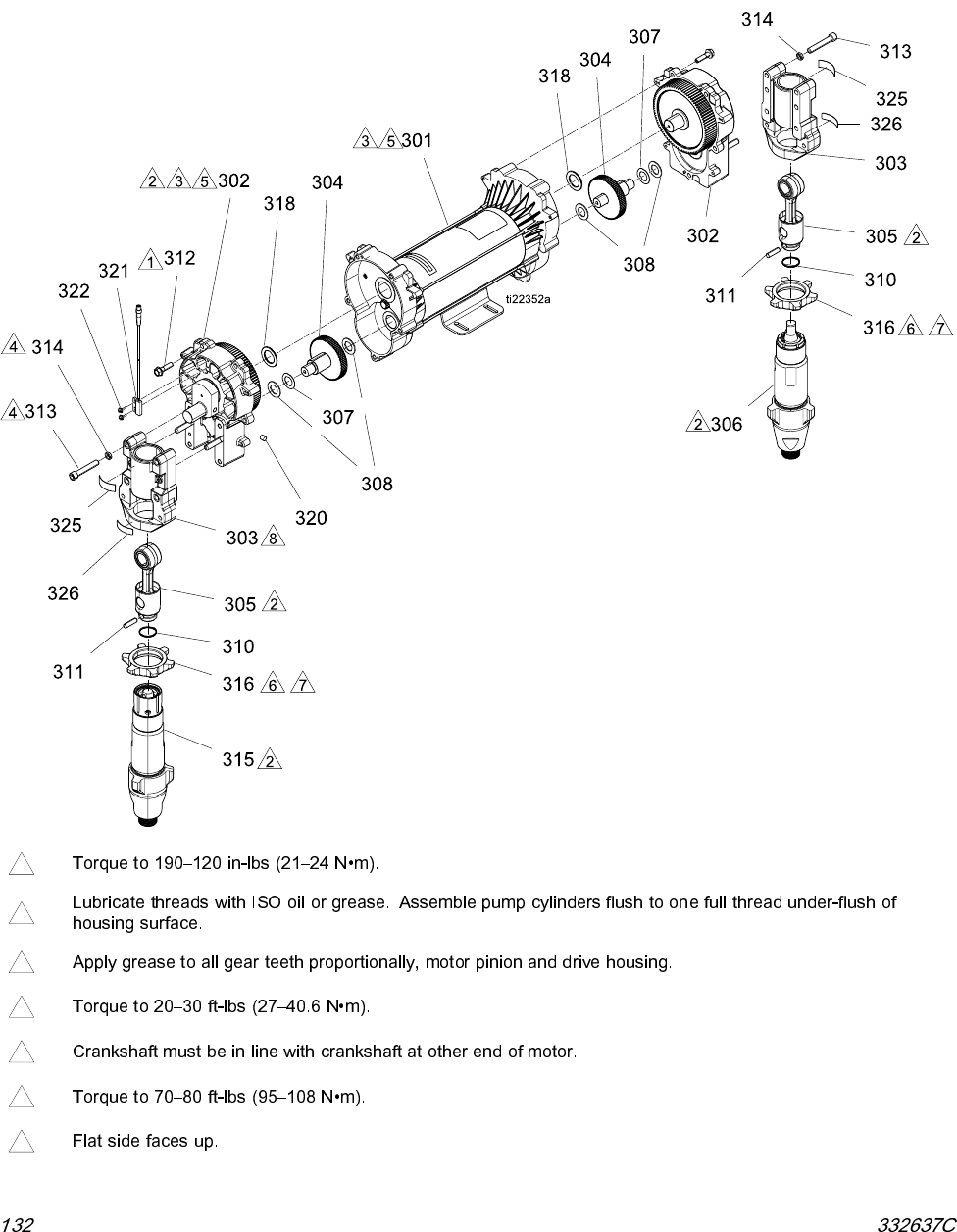
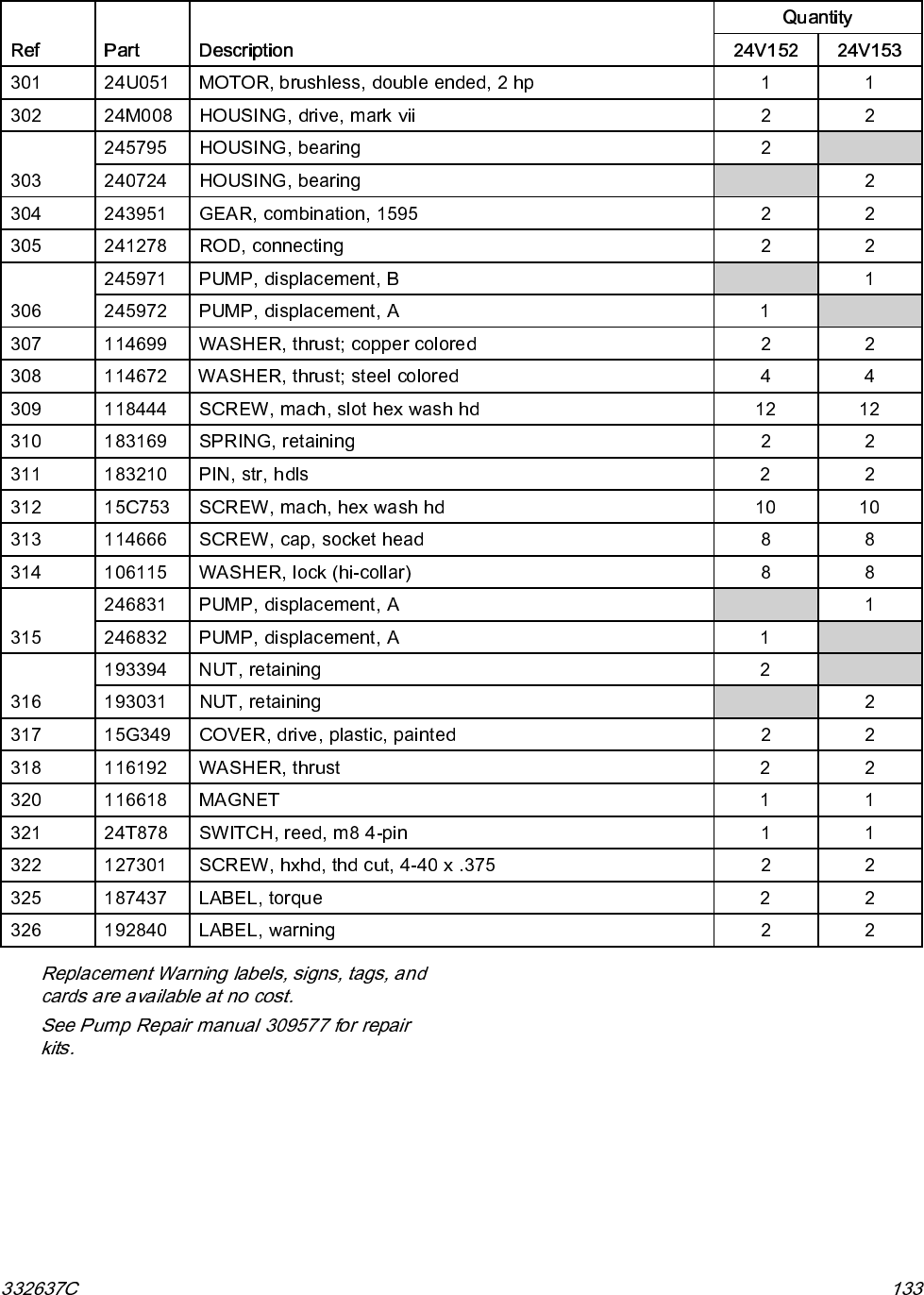
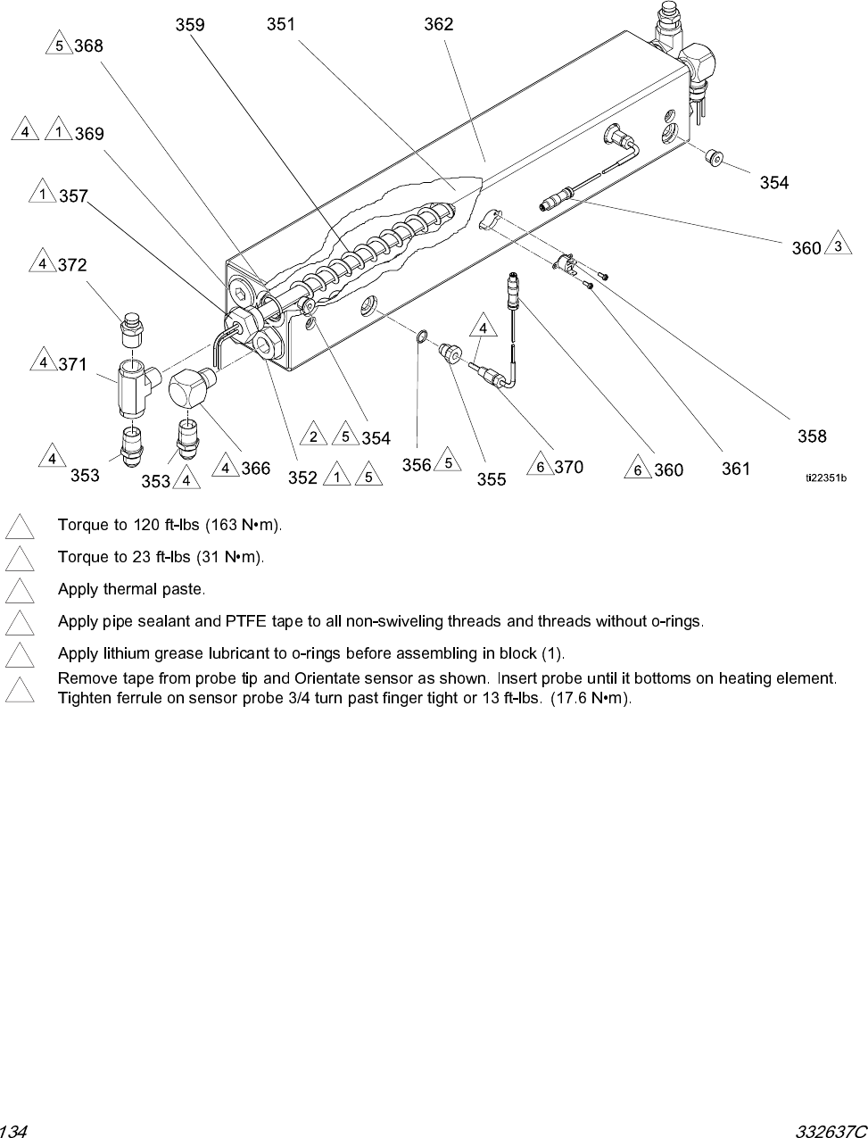
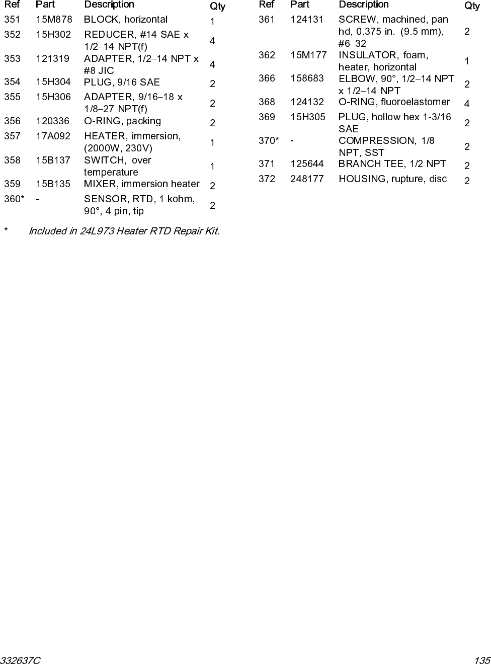
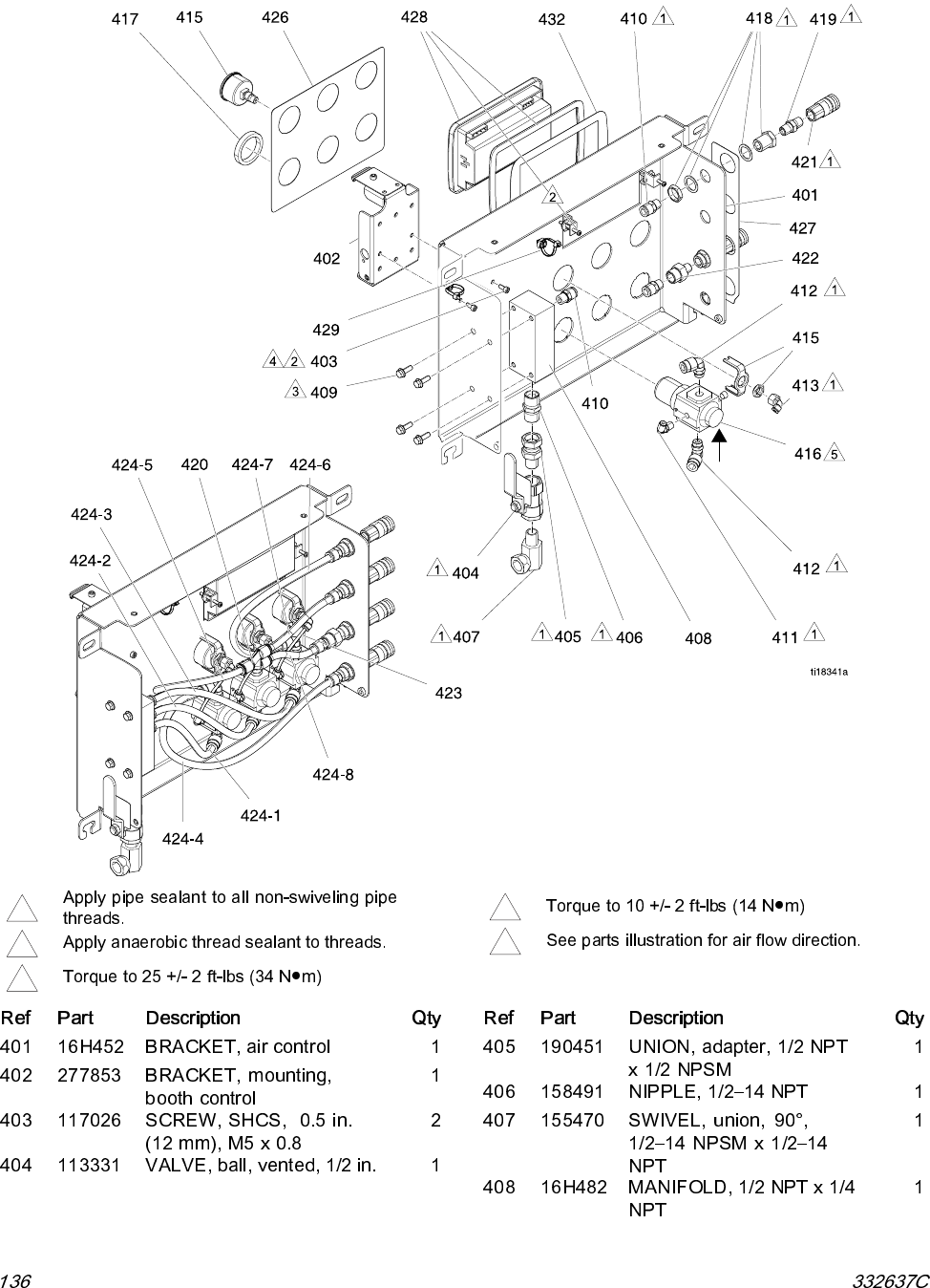
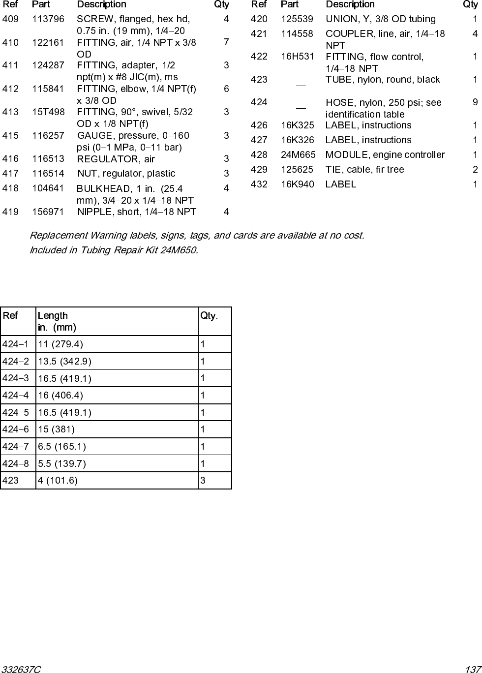
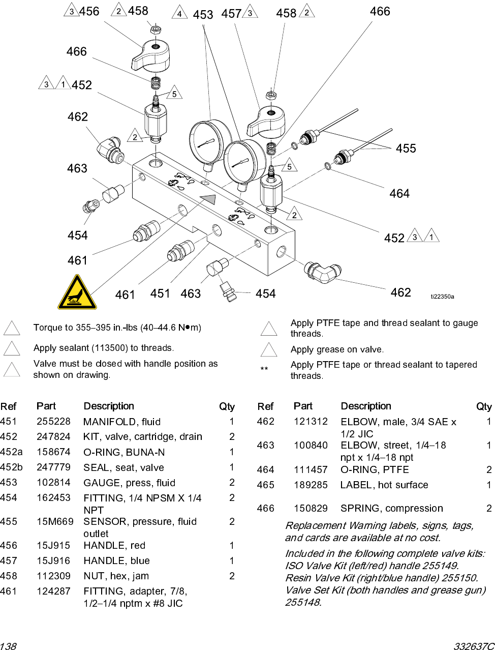
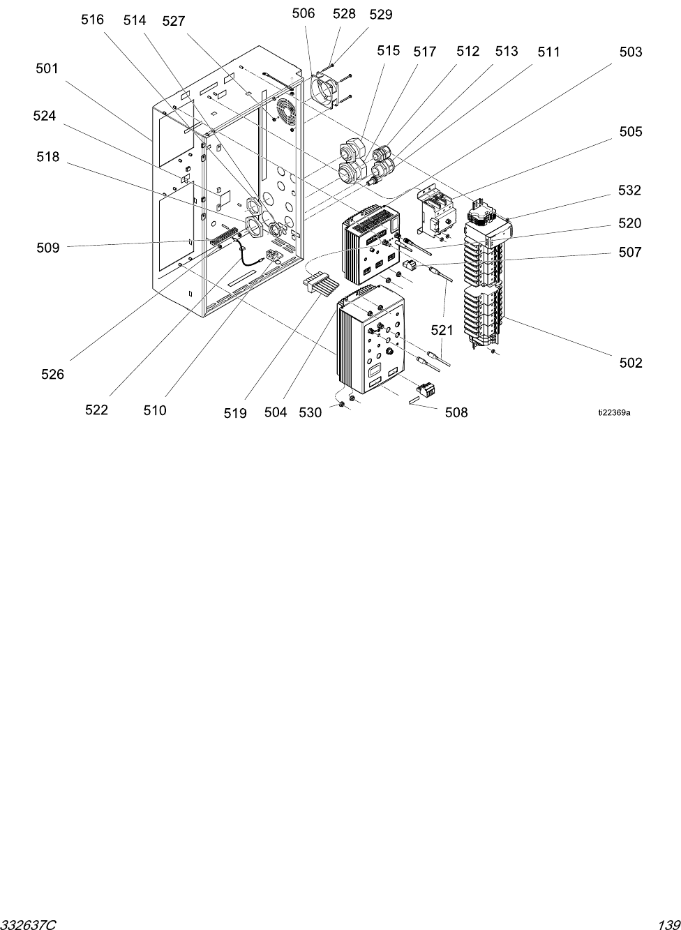
Repair-Parts
Reactor® 2 Elite Integrated
Proportioning System
332637C
PROVEN QUALITY. LEADING TECHNOLOGY.


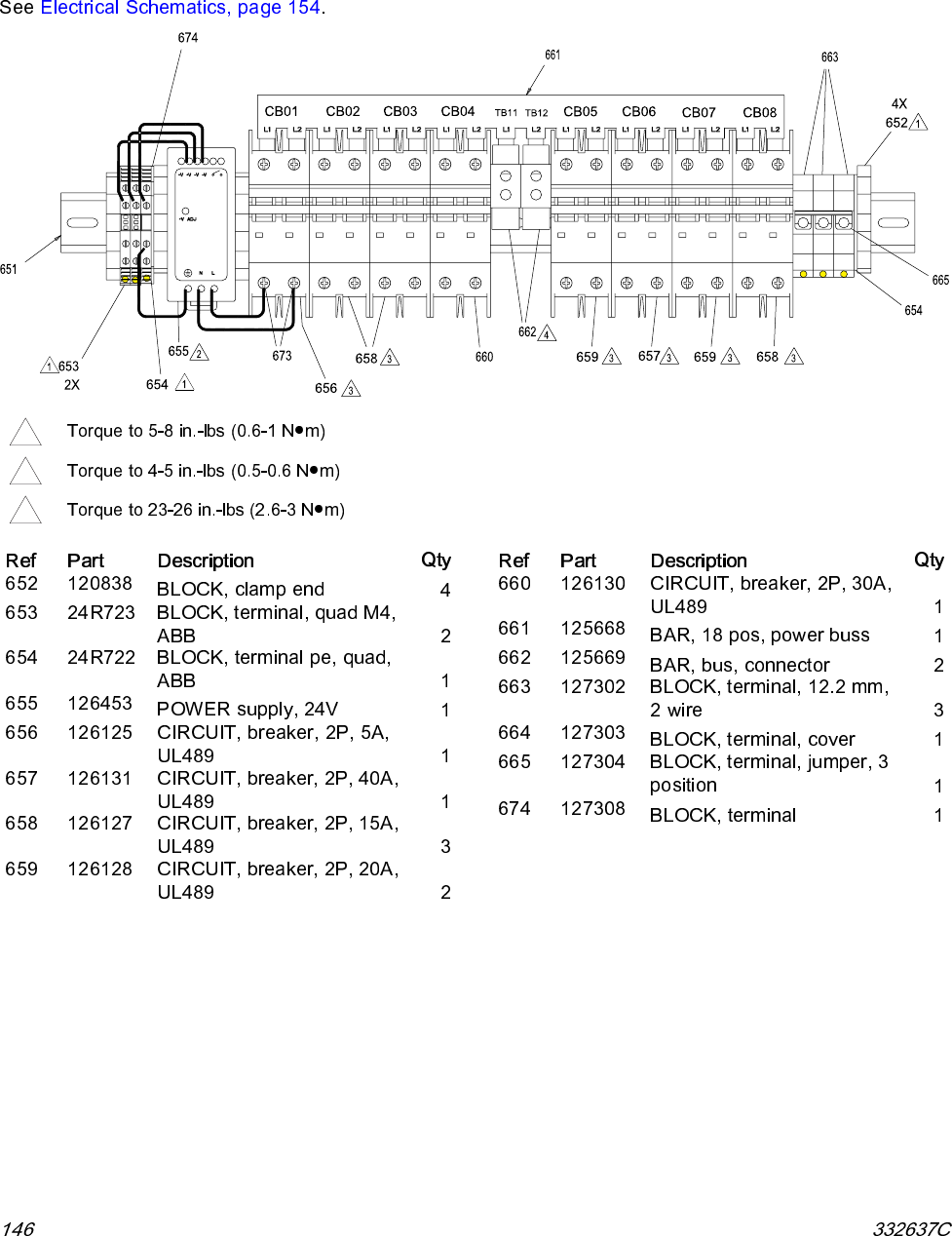
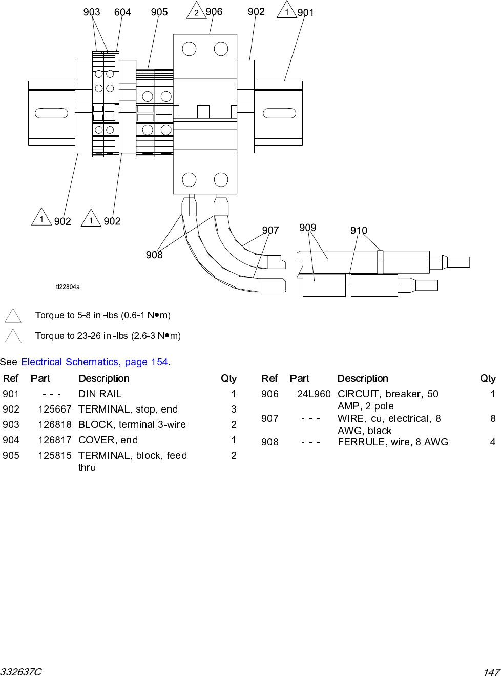
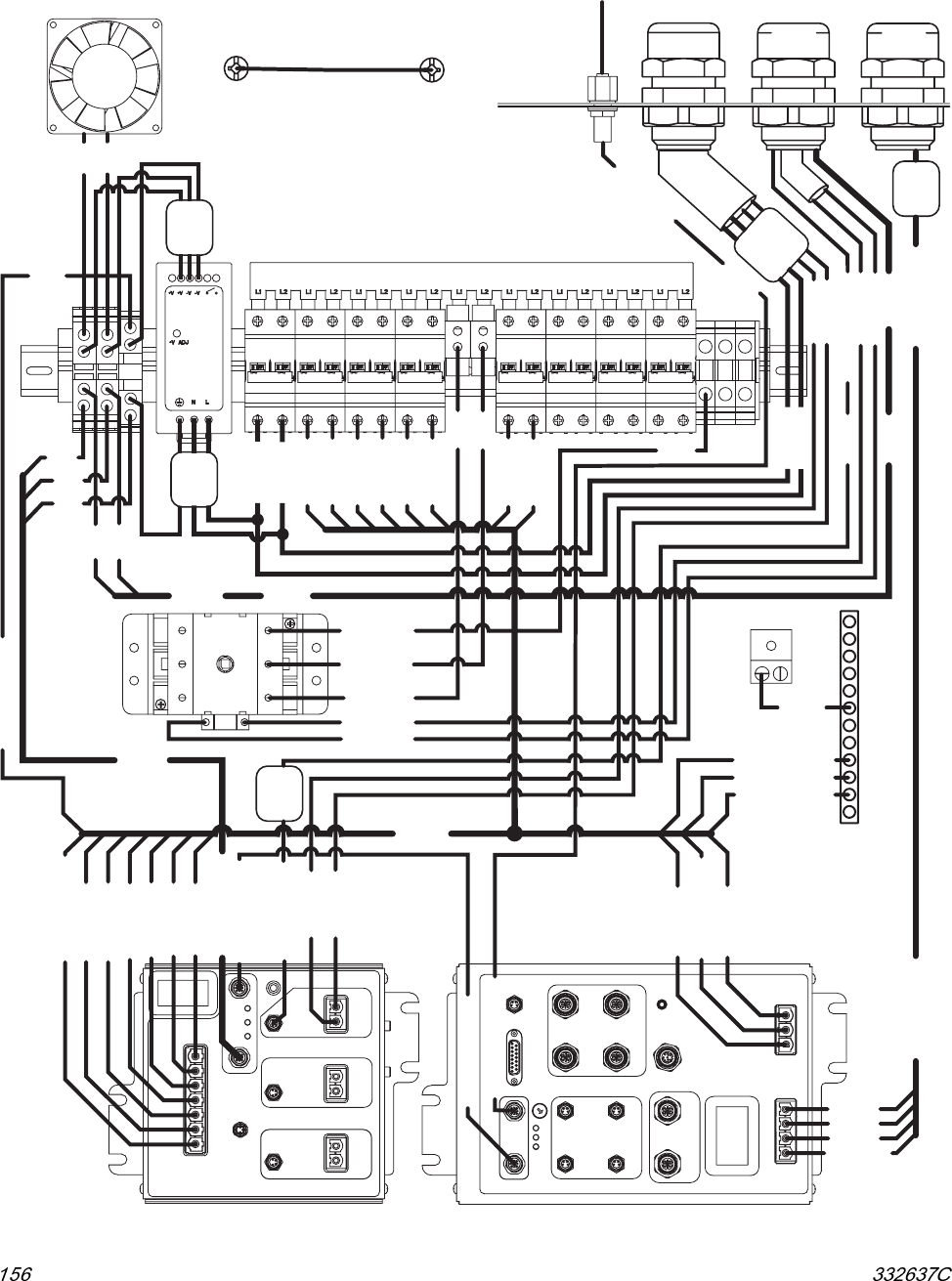
Electrical Schematics
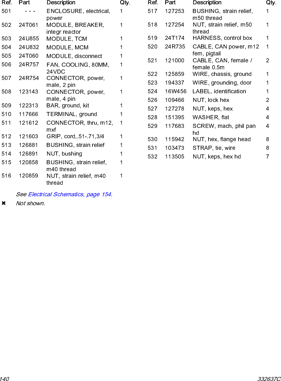
Electrical Enclosure Wiring Diagram
DOOR GROUND WIRE
194337
DOOR
STUD
BOX
STUD
CB01 CB02 CB03 CB04 CB05 CB06 CB07 CB08
5A 15A 15A 30A 20A 40A 20A 15A
CIRCUIT BREAKER
DIN RAIL 24T061
BULKHEAD
121612
FAN 24U848
NEUTRAL
GB01
GROUND TERMINAL
117666
125859
GB02
GROUND BAR
122313
DISCONNECT
24T060
PS1
MCM
24U832
TCM
24U855
RED
BLK
P010 BLK
P020 RED
P030 BLK
P040 RED
P050 BLK
P060 RED
P070 BLK
P080 RED
K100 BLK
K110 RED
K120 WHT
P090 GRN / YEL
P100 GRN / YEL
P060 RED
P050 BLK
P040 RED
P030 BLK
P020 RED
P010 BLK
P070 BLK
P090 GRN / YEL
P080 RED
P110 GRN / YEL
P100 GRN / YEL
P110 GRN / YEL
BRN
BLU
BLK
K100
K110
BLK
WHT
GRN / YEL
K120
16K229
BREAKER HARNESS
24T174
CAN 121000
24R735
P110
H100 ORG
H110 ORG
H110 ORG
H100 ORG
GRN / YEL
1 BLK
2 BLK
3 BLK
MOTOR 24U049 MOTOR 24U049
CAN 121000
'TCM-CAN1 PS1'
'TCM-CAN2 MCM'
'MCM-CAN-1 TCM'
'MCM-CAN-2 CAN-1'
'CAN-1 MCM'
N080 BLK
N080 BLK
N060 BLK
N060 BLK
24T198
N120 BLK
N130 BLK
N120 BLK
N130 BLK
'TCM H HT-RTD-H'
'TCM-H HT-RTD-H'
24T241
24T241
FERRITE
BEAD
125839
FERRITE
BEAD
16Y516
FERRITE
BEAD
16Y509
CORD GRIP
CORD GRIP
121000
CABLE 24T198
TO CIRC PUMP
TO REACTOR BOX
'CAN-1 ADM'
123652
121603 127253
127254
126881
126891
CORD GRIP
CABLE 122837
CABLE 24T241
TO REACTOR BOX
122837
'24 VDC'
'24 VDC'
HOSE
CT01
POWER
SUPPLY
FERRITE
BEAD
16Y516
FERRITE
BEAD
16Y516
23
45
67
89
10
11
14
12
13
15 16
AB
OVER
TEMP
CABLE 16K229
TO LOAD CENTER
ti23006a
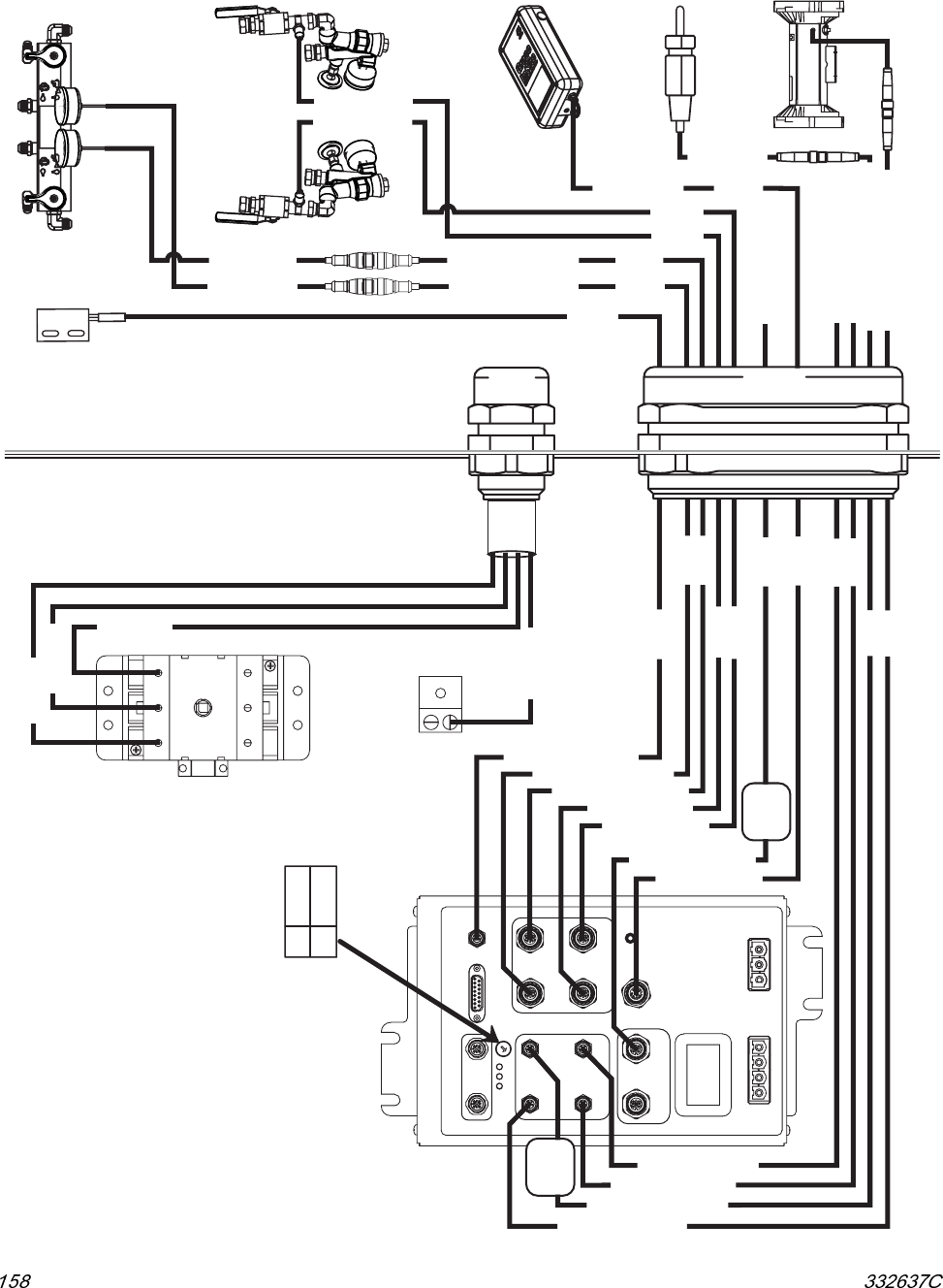
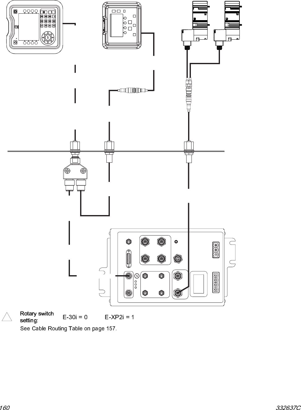
Electrical Schematics
MCM Wiring Diagram
MCM
24U832
23
45
67
89
10
11
14
12
13
15 16
DISCONNECT
24T060
CT01
CORD GRIP
SENSORS
127253
127254
CORD GRIP
ALTERNATOR
120858
120859
GB01
GROUND TERMINAL
117666
125753
CABLE 'K' 125753
TO 120/240 VAC
ALTERNATOR
MOTOR
CYCLE SWITCH
PRESSURE
SENSOR A
15M669
INLET
SENSOR B
24U851
INSITE
16X118
ENGINE
COOLANT
RTD 24L974
MOTOR
24U051
'MCM-12 CYCLE-CNT'
'MCM-6 PRESSURE-A'
'MCM-7 PRESSURE-B'
'MCM-8 INLET-A'
'MCM-9 INLET-B'
'MCM-11 LOAD-CTR'
'MCM-14 INSITE'
'MCM-5 HX-RTD-B'
'MCM-4 HX-RTD-A'
'MCM-3 RTD-ENGINE'
'MCM-2 MOTOR-OT'
K070 WHT
K030 BLK
K050 RED
K010 GRN
24T878
24T878
FLUID MANIFOLD
PRESSURE
SENSOR B
15M669
127286
127286
127286
127286
'PRESSURE-A MCM'
'PRESSURE-B MCM'
PRESSURE-A
PRESSURE-B
INLET
SENSOR A
24U851
16W131
16W131
16W131
16W131
'INLET-A MCM'
'INLET-B MCM'
RTD-ENGINE
'RTD-ENGINE MCM'122837 122837
MOTOR-OT
125357 125357 'MOTOR-OT MCM'
TO LOAD CENTER
TO REACTOR BOX
TO REACTOR BOX
125357
125357
123656
24T051
24T051
'INSITE MCM'
ELECTRICAL ENCLOSURE
0
1
E-30i
E-XP2i
ROTARY SWITCH SETTING
FERRITE
BEAD
125839
FERRITE
BEAD
119253
ti23006a
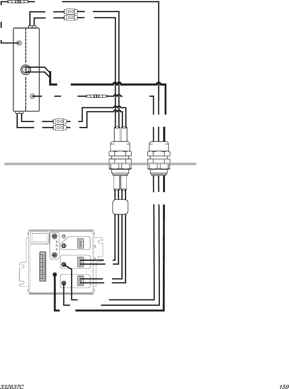
Electrical Schematics
Booster Heater Wiring Diagram
TCM
24U855
HOSE
AB
OVER
TEMP
FERRITE
BEAD
16Y509
126881
126891
CORD GRIP
MOTOR
BOOST HEAT
CORD GRIP
SENSORS
127253
127254
24T199
24T199
OT SWITCH 15B137
BOOST HEATER
24V145
HEATER A
RTD B
RTD A
HEATER B
261821
261821
24T199
24T199
CAN
'TCM-B HT-B'
'TCM-A HT-A'
'HT-B TCM-B
'HT-A TCM-A'
16A111
16A111
BLK
BLK
BLK
BLK
BLK
WHT
BLK
WHT
BLK
WHT
BLK
WHT
24L973
24L973
24T242 24T242
125357
125358
125357
125358
TCM-OT
HTR-OT
'TCM-A HT-RTD-A'
'TCM-B HT-RTD-B'
HT-RTD-B
HT-RTD-A
'HT-RTD-B TCM'
'HT-RTD-A TCM'
ELECTRICAL ENCLOSURE
ti23006a
Electrical Schematics
Optional Remote Display Module and Feed Pump Kit Wiring Diagram
MCM
24U832
'MCM-CAN-2 CAN-1'
23
45
67
89
10
11
14
12
13
15 16
'CAN-1 ADM' 123652
'CAN-1 MCM'
CAN 2
CAN 1
121000
121000 123652
124003
ELECTRICAL ENCLOSURE
BULKHEAD
121612
BULKHEAD
121612
'ADM-CAN-1 CAN-1'
SPLITTER
124654
ADM 24U854
DM 24L952
REMOTE DISPLAY
122030
SPLITTER
125982
BULKHEAD
121612 SOLENOID
16K335
SOLENOID
16K335
FEED PUMP SHUTOFF
123656
ti23006a
1
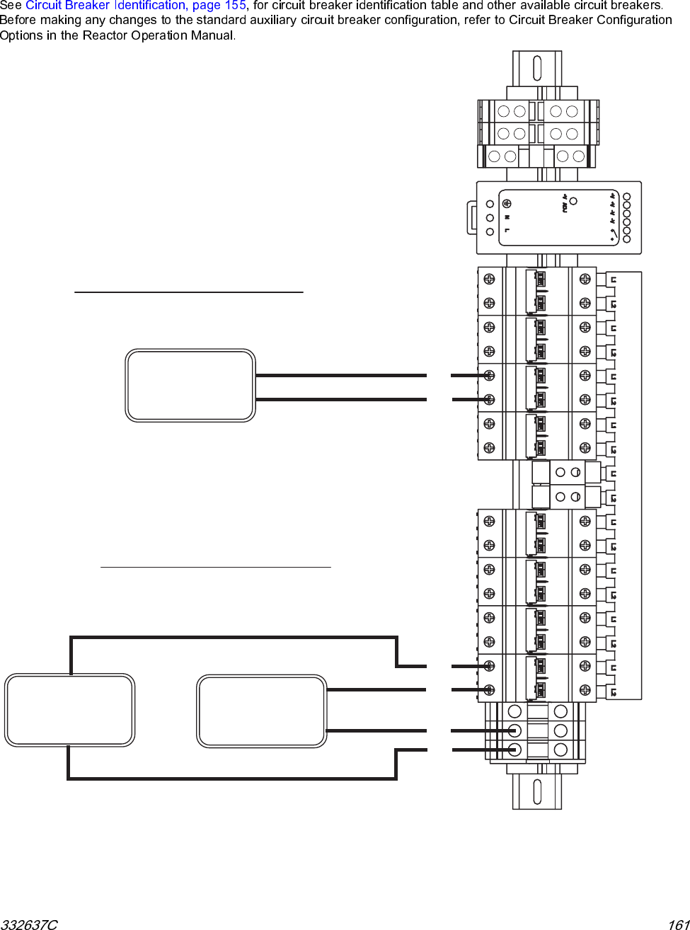
Electrical Schematics
Optional Customer Auxiliary Power Wiring Diagram
CB01 CB02 CB03 CB04 CB05 CB06 CB07 CB08
5A 15A 15A 30A 20A 40A 20A 15A
NEUTRAL
PS1
POWER
SUPPLY
240 VAC
AUXILIARY LOAD
120 VAC
AUXILIARY LOAD
NEUTRAL
NEUTRAL
120 VAC
AUXILIARY LOAD
L1
L2
L1
L2
N
N
LINE TO NEUTRAL WIRING
LINE TO LINE WIRING
240 VAC AUXILIARY LOAD
120 VAC AUXILIARY LOAD
CIRCUIT BREAKER DIN RAIL 24T061
ti23006a
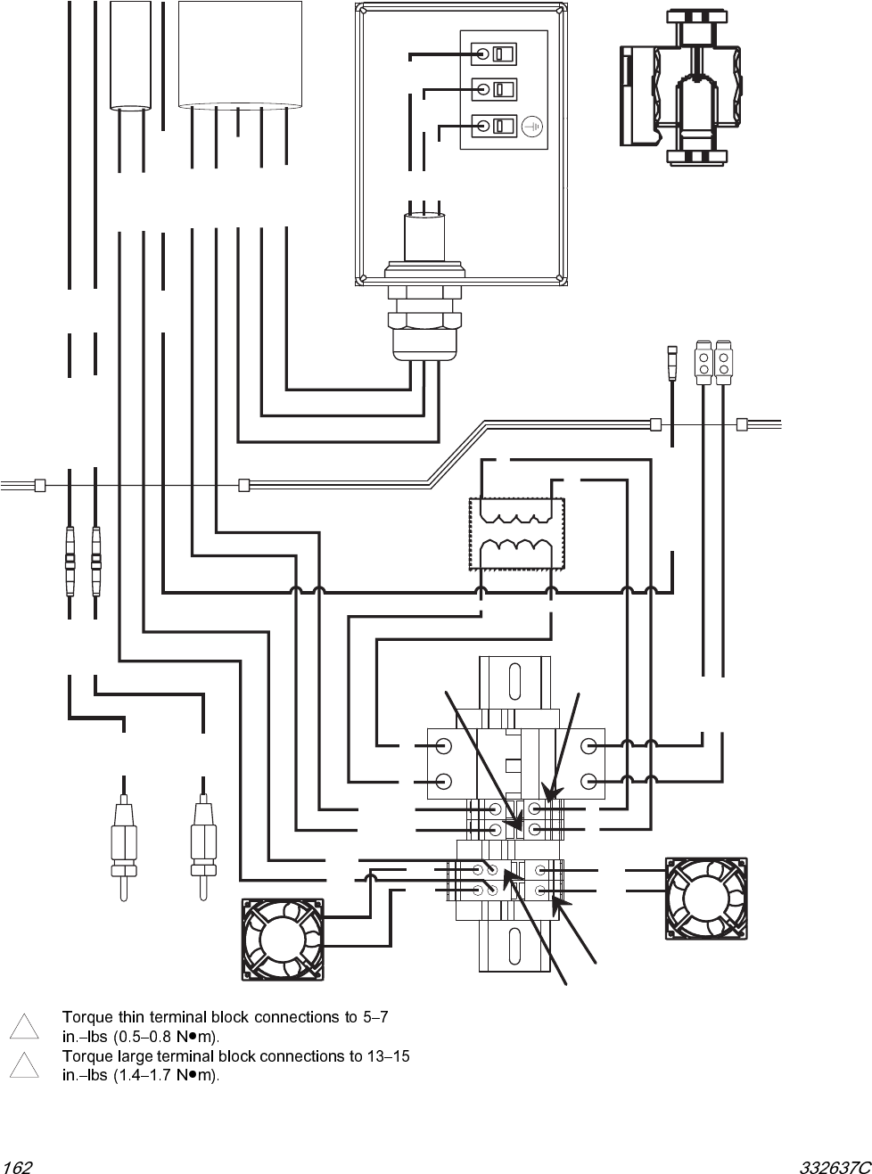
Electrical Schematics
Reactor Cabinet Wiring Diagram
CB20
TB22
TB21
TB23
TB24 TRANSFORMER
PRIMARY
SECONDARY
N220 BLK
N210 BLK TO HEATED HOSE POWER
TO HEATED HOSE POWER
BLK
BLK
24T198
CORD GRIP
260067
CABLE 125357
CABLE 24T241
CABLE 122837
HARNESS 24T198
TO POWER DISTRIBUTION BOX
COOLANT PUMP JUNCTION BOX
COOLANT PUMP
24L915
GRN / YEL
NL
N040
N060
N080
HARNESS
24T198
TO POWER
DISTRIBUTION
BOX
CABLE 24T241
24 VDC
REACTOR ENCLOSURE
HEAT EXCHANGER RTD A
HEAT EXCHANGER RTD B
24L972
24L972
125357
125357
122837
TO HEATED HOSE RTD
'HT-RTD-H TCM-H'
'HT-RTD-H TCM-H'
'HX-RTD-A MCM'
'HX-RTD-B MCM'
HX-RTD-A
HX-RTD-B
BLK
WHT
BLK
WHT
RED
BLK
RED
BLK
N080- BLK
N060 BLK
N040 GRN / YEL
N120 BLK
N130 BLK
N120 BLK
N130 BLK
1
2
3
4
34
12
HOSE BREAKER
DIN RAIL 24T059
CABINET FAN
24U847
MOTOR FAN
24U847
ti23006a
1
2
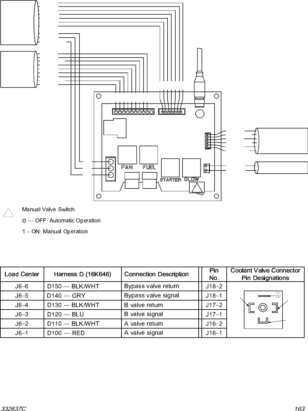
Electrical Schematics
Load Center Wiring Diagram
TO ENGINE
CONTROL
MODULE
HARNESS ‘F’
16K297
F110 - BRN
F100 - BLK/YEL
F080 - PUR
F070 - WHT
F120 - BLU
F040 - ORG
F030 - GRY
F010 - BLK/YEL
‘LO ADC TR -J4 MCM’
HAR NESS, 1236 56
TO ENGINE
HARNESS ‘E’
16K301
TO ELECTRICAL ENCLOSURE
HARNESS ‘H’
16K299
TO COOLANT VALVES (12 VDC)
HARNESS ‘D’
16K646
E630
E620
E611
E150
E100
E200
E190
J3
J6
J4
1
1
LOAD CENTER
RELAY REPAIR KIT
24L958
FUSE REPAIR KIT
24L959
(contains four replacement relays)
(contains two replacement fuses)
LOAD CENTER REPAIR KIT
24L957
J5
J11
11
J2
F1 20
F1 10
F1 00
F0 80
F0 70
F0 40
F0 30
F0 10
E020
E220
E010
1
E620 - BRN
E611 - BLK
E150 - WHT
E100 - ORG
E630 - BLU
E200 - GRY
E190 - TAN
E020 - RED
E220 - PUR
E010 - BLK/WHT
K3
K2
K1
F3 F4
K4
CR4
D140 - GRY
D130 - BLK/WHT
D120 - BLU
D150 - BLK/WHT
D100 - RED
D11T
0 - BLK/WH
H100 - ORG
H110 - ORG
F020 - RED
F0 20
ti23006a
1
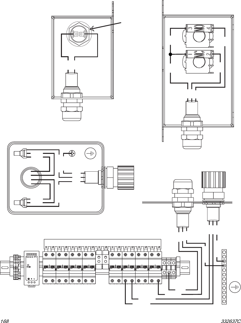
Coolant Valve (12 VDC) Wiring Diagram
PIN 2 PIN 1
PIN
UNUSED
Electrical Schematics
Engine Control Module Wiring Diagram
FERRITE
BEAD
125835
TO 120 / 240 VAC
ALTERNATOR
HARNESS 'M', 16Y518
RED
BLK
M040
M020
24M665, ENGINE CONTROL MODULE
16
N
M060
TO LOAD CENTER
HARNESS 'F', 16K297
DSE PIN 16
F010
F020
F030
F040
F070
F080
F100
F110
F120
F010 BLK / YEL
F020 RED
F030 GRY
F040 GRN
F070 WHT
F080 PUR
F100 BLK / YEL
F110 BRN
F120 BLU
ti23006a
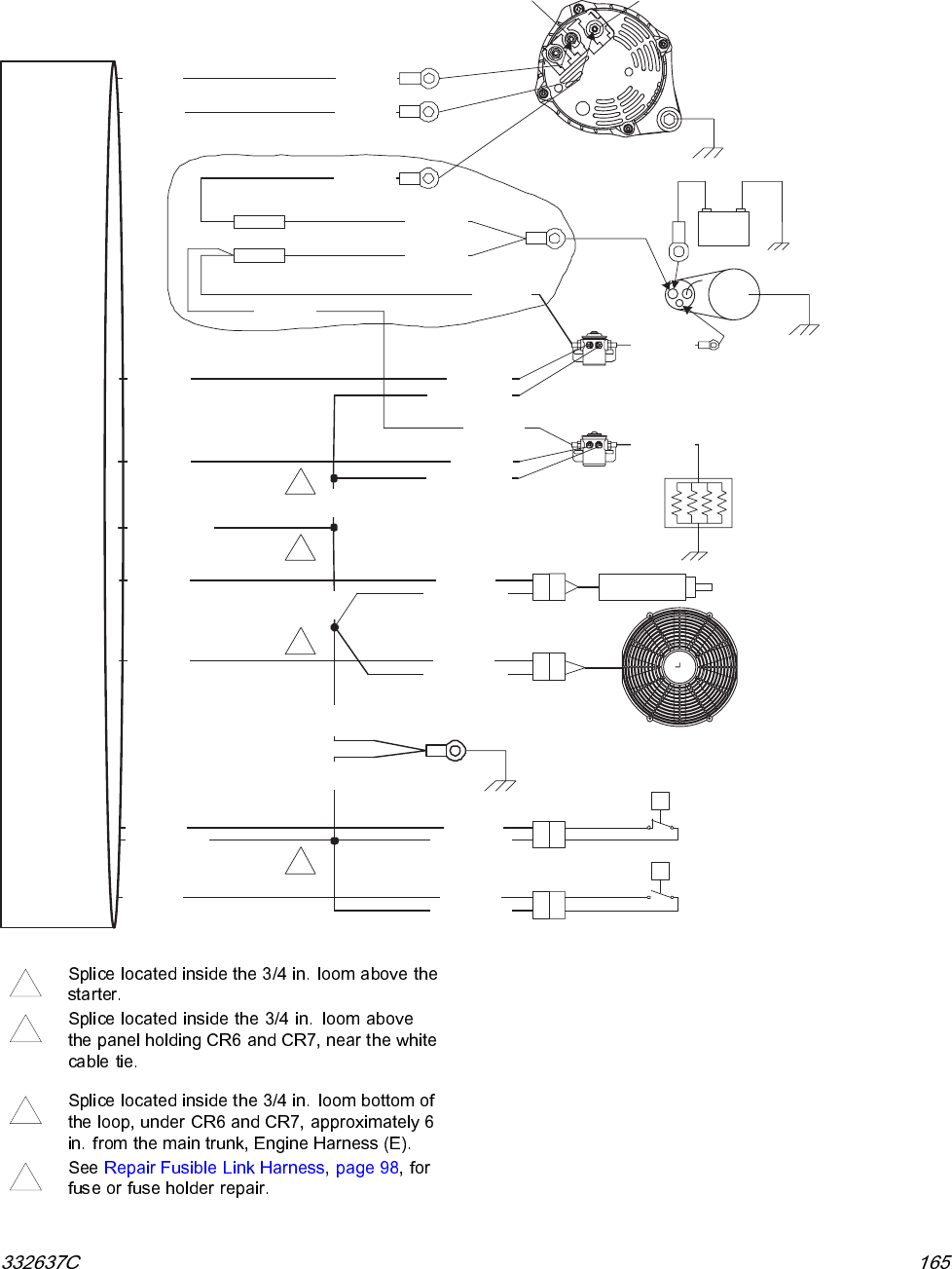
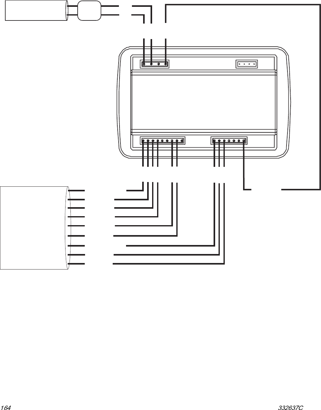
Electrical Schematics
Engine Wiring Diagram
TO LOAD CENTER
HARNESS ‘E’
16K301
E630 - BLU
E611 - BLK/YEL
E100 - ORG
E620 - BRN
E190 - TAN
E180 - WHT
E032 - BLK/WHT
E034 - BLK/WHT
SINGLE POINT
GROUND
E112 - BLK/WHT
E111 - BLK/WHT
E613 - BLK/YEL
E612 - BLK/YEL
E620 - BRN
E630 - BLU
E150 - WHT
E190 - TAN
E200 - GRY
C020 - RED
E220 - PUR
E0 31
SP4
SP2
E033
SP1
E035
SP3
E6 14
E140 - ORG
C050 - RED
C040 - RED
C050 - RED
GLOW PLUG
SOLENOID RELAY
CR7
“BOTTOM”
STARTER
ENGINE
STARTER
ES
12V
CHARGE ALTERNATOR
SOLENOID RELAY
CR6
“TOP”
FUEL SHUTOFF
SOLENOID
P
T
F9
E031 - BLK/WHT
F8 C010 - RED
C030 - RED
E020 - RED E020 - RED
FUSIBLE LINK HARNESS ‘C’, 24L964
FUSE, 16P405, FUSE HOLDER, 16P406
E033 - BLK/WHT
E035 - BLK/WHT
E614 - BLK/YEL
RADIATOR FAN
OIL PRESSURE SWITCH
WATER TEMPERATURE
SWITCH
J7
J8
J10
J11
GLOW PLUGS
FD
+-
2
3
1
1
E150 - WHT
E200 - GRY
E220 - PUR
E010 - BLK/WHT
E100 - ORG
D+ B+
ti23006a
1
2
3
4
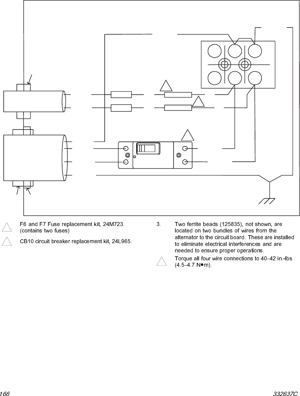
Electrical Schematics
Alternator Enclosure Wiring Diagram
M070-WHT
W2
U1 V1 W1
V2U2
TO ENGINE CONTROL
MODULE
HARNESS 'M',125752
F6, 2 AMP
F7, 2 AMP
BLK
K020-BLK
125754
K040-RED
125755
BLK
K080-WHT
125822
ALTERNATOR ENCLOSURE
SP11
SP12
BLK
BLK
120858 120859
HARNESS 'K',125753
125631
90 AMP
CB10
2
1
1
TO POWER
DISTRIBUTION BOX
K010 - GRN
K070-WHT
K030-BLK
M040-RED
M020-BLK
1
2
43
K050 - RED
ti23006a
1
2
4
Electrical Schematics
Air Compressor Junction Boxes
24U078
24U080
WHT
BLK
GRN
WHT
BLK
GRN
WHT
BLK
RED
24U079 WHT
BLK
GRN
24U076
GROUND
STUD
WHT
BLK
16X011
AC-OT1
AC-OT2
BLK 5
BLU 1
RED 8
YEL 4
AC-W1-W5 AC-W4-W8
AC-GND
SS-1 SS-3
SS-2
SS-4
PD-GND2
PD-GND2
PD-CB6-2
PD-CB6-4
PD-CB8-4
PD-N
GND2
GROUND BAR
122313
CB01 CB02 CB03 CB04 CB05 CB06 CB07 CB08
5A 15A 15A 30A 20A 40A 20A 15A
CORD GRIP
260067
117625
CORD GRIP
16M862
CORD GRIP
16M862
CORD GRIP
260067
117625
CORD GRIP
260067
117625
CABLE 24U078
TO MOTOR STARTER
CABLE 24U080
TO MOTOR STARTER
CABLE 24U079
TO MOTOR STARTER
CABLE 16X011
TO MOTOR STARTER
CABLE 24U076
TO MOTOR STARTER
MOTOR JUNCTION BOX
AIR COMPRESSOR OVER TEMPERATURE BOX
AIR COMPRESSOR START STOP BOX
ELECTRICAL
ENCLOSURE
BREAKER DIN RAIL
24T061
WIRE NUT
#6
STOP
SWITCH
START
SWITCH
OVER
TEMPERATURE
SENSOR
NEUTRAL
WIRE NUT
#6
ti23338a
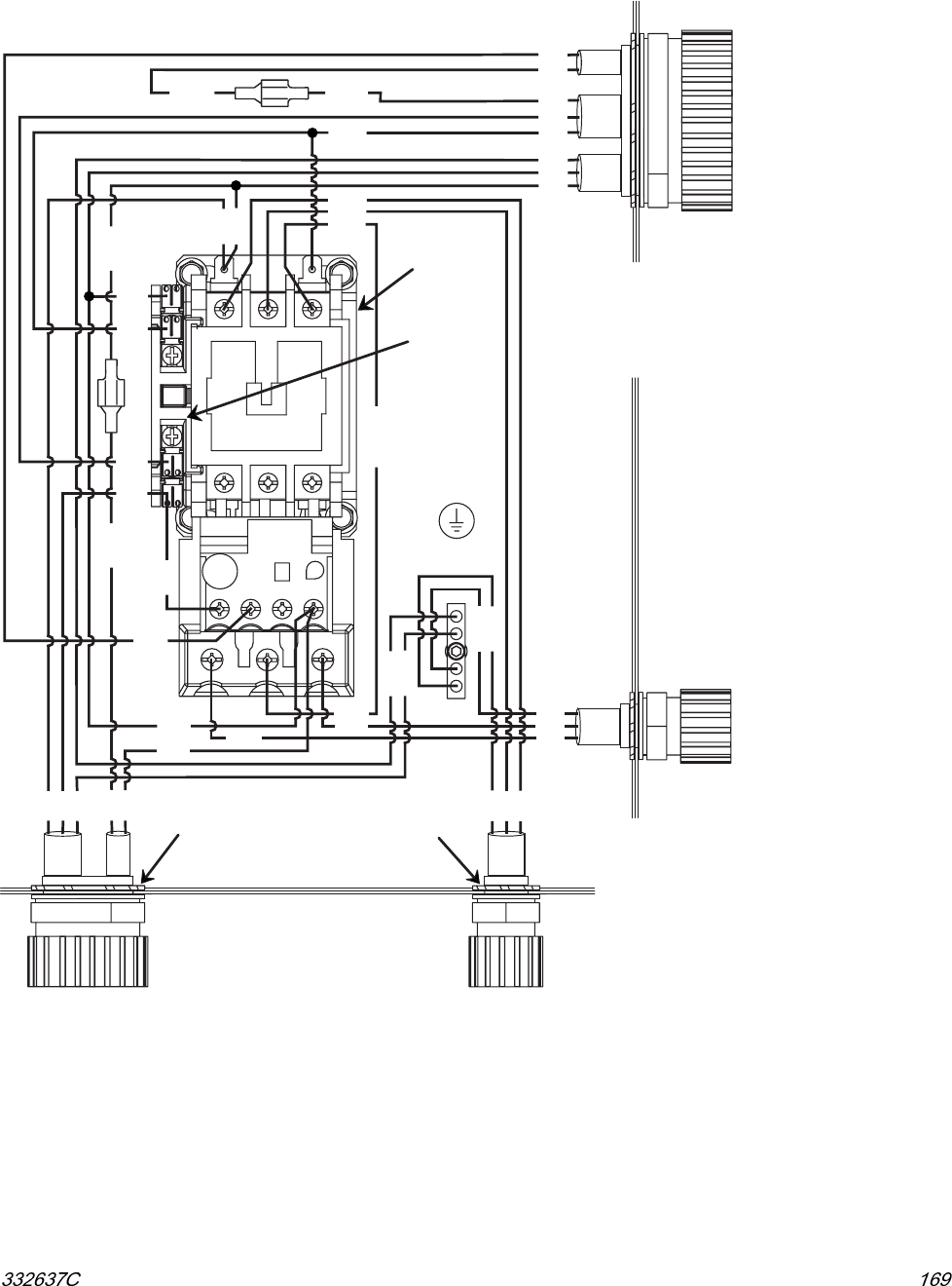
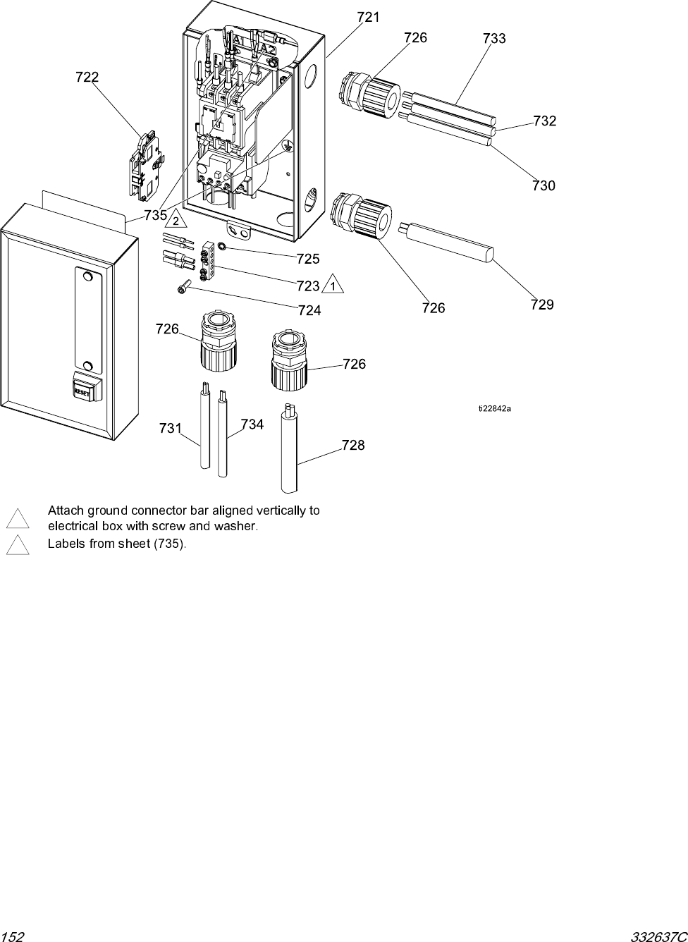
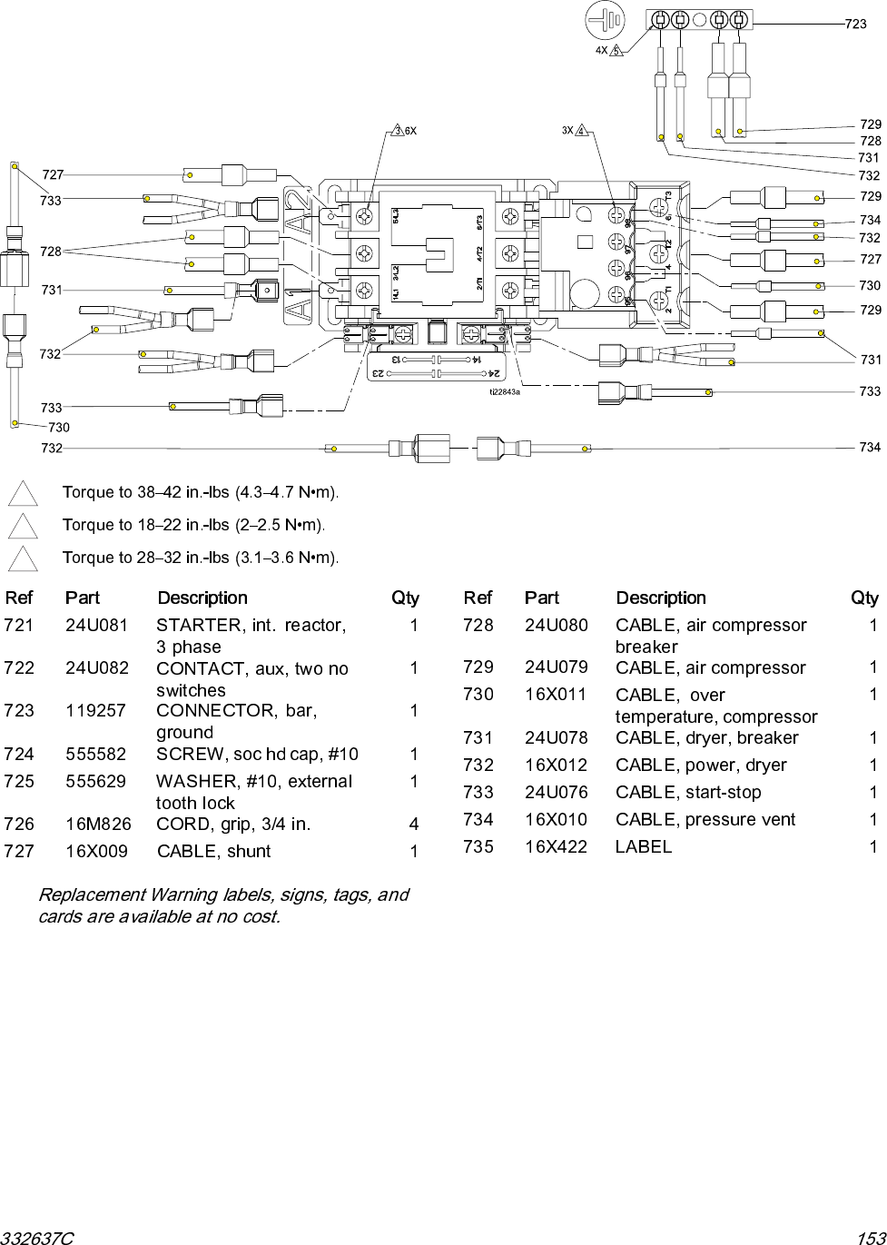
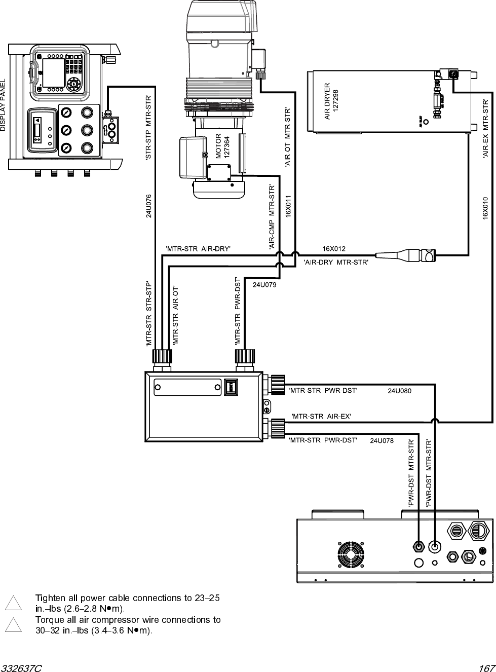
Electrical Schematics
Motor Starter
L1 L2 L3
T1 T2 T3
95 96 97 98
A1 A2
13
14
23
24
WHT
MS-T3
MS-T1
MS-GND
MS-GND
MS-T2
16X009 BLK
WHT
BLK
GRN
24U080
BLK
GRN
MS-GND
MS-GND
MS-98
MS-98
WHT
BLK
GRN
BLK
WHT
BLK
GRN
WHT
WHT
BLK
RED
WHT
BLK
MS-QD1
MS-QD1
MS-L1
MS-L2
MS-L3
MS-A2
MS-A1
MS-A1
MS-23
MS-13
MS-14
MS-24
MS-96
MS-95
MS-QD2
MS-QD2
GROUND BAR
119257
CORD GRIP
16M826
CORD GRIP
16M826
CORD GRIP
16M826
CORD GRIP
16M826
CABLE 16X011
TO COMPRESSOR OVER TEMP SENSOR
CABLE 24U076
TO COMPRESSOR START STOP BOX
CABLE 16X012
TO AIR DRYER
CABLE 24U079
TO AIR COMPRESSOR
CABLE 24U080
TO ELECTRICAL ENCLOSURE
AIR COMPRESSOR POWER
CABLE 24U078
TO ELECTRICAL ENCLOSURE
AIR DRYER POWER
CABLE 16X010
TO AIR EXHAUST VALVE
Motor STARTER
WITH BOX
24U081
16X010
24U078
AUXILIARY
CONTACTOR
24U082
24U079
16X012
24U076
16X011
ti23006a

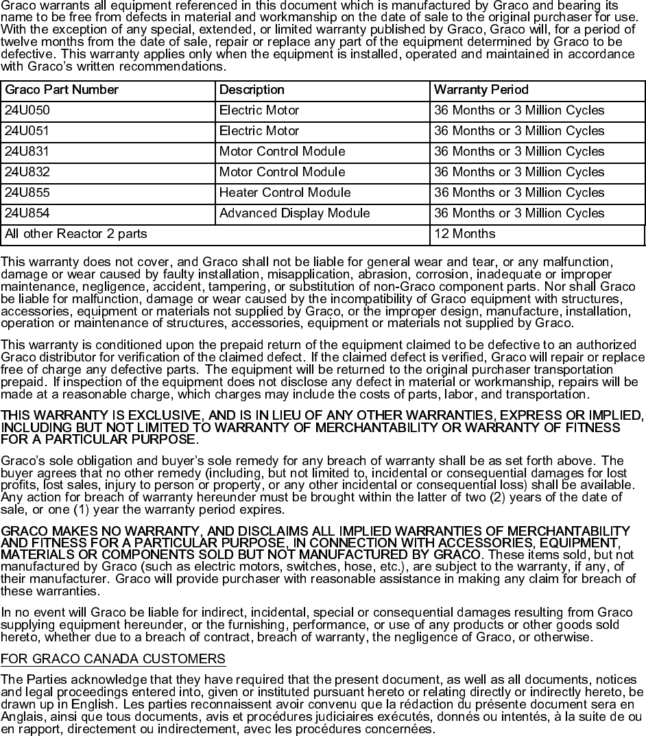
Graco Extended Warranty for Integrated Reactor
®
2 Components

Graco Information
