Graco 333394H Truecoat Electric Airless Sprayer Users Manual Project Series Paint Sprayers (English)
2015-04-02
: Graco Graco-333394H-Truecoat-Electric-Airless-Sprayer-Users-Manual-686190 graco-333394h-truecoat-electric-airless-sprayer-users-manual-686190 graco pdf
Open the PDF directly: View PDF ![]() .
.
Page Count: 32
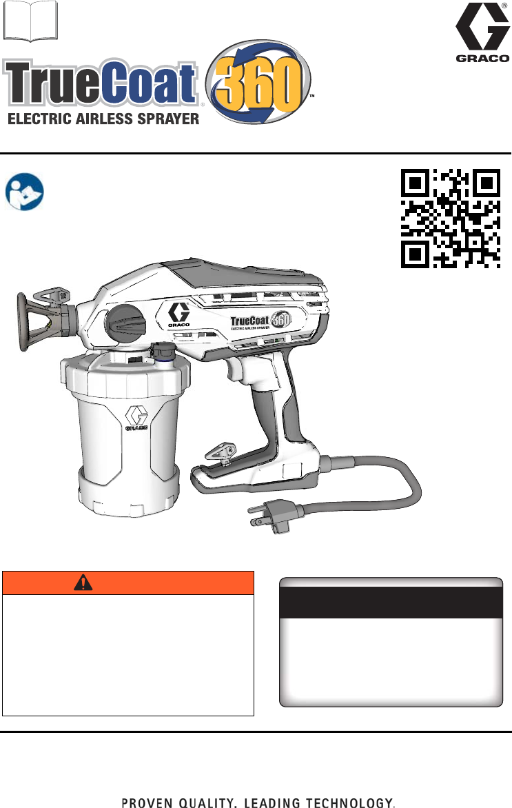
For portable spray applications of water-based and oil-based
non-flammable architectural paints and coatings only.
For Household Use Only.
Not approved for use in explosive atmospheres or hazardous locations.
ti24021a
Have a Question?
Call toll-free:
1-888-541-9788
Or visit us at:
www.paintsprayersbygraco.com
333394H
EN
Important Safety Instructions
Read all warnings and instructions in this manual and on the
unit, including the power cord. Be familiar with the controls and
the proper usage of the equipment. Save these instructions.
Owners Manual
Project Series Paint Sprayers
WARNING
To avoid fire and explosion, use only
non-flammable or water-based materials, or
non-flammable paint thinners. Do not use
materials which state “FLAMMABLE” on the
packaging. For more information about your
material, request MSDS from distributor or
retailer.
Use oil based materials outdoors or in a
well-ventilated area with a flow of fresh air.
Scan QR code or click on link
for operational video.
http://graco.com/tc360op

Contents
2333394H
Contents
Important User Information . . . . . . . . . . . . . . . . . . . . . . . . . . . . . . . . . . . . . . . . . . . . . . 3
Important Safety Information . . . . . . . . . . . . . . . . . . . . . . . . . . . . . . . . . . . . . . . . . . . . . 4
Component Identification . . . . . . . . . . . . . . . . . . . . . . . . . . . . . . . . . . . . . . . . . . . . . . . . 7
Start Up . . . . . . . . . . . . . . . . . . . . . . . . . . . . . . . . . . . . . . . . . . . . . . . . . . . . . . . . . . . . . . 8
Starting a New Job . . . . . . . . . . . . . . . . . . . . . . . . . . . . . . . . . . . . . . . . . . . . . . . . . . . 8
Refilling FlexLiner . . . . . . . . . . . . . . . . . . . . . . . . . . . . . . . . . . . . . . . . . . . . . . . . . . . 10
How to Spray . . . . . . . . . . . . . . . . . . . . . . . . . . . . . . . . . . . . . . . . . . . . . . . . . . . . . . . . . 11
Dual Speed Control . . . . . . . . . . . . . . . . . . . . . . . . . . . . . . . . . . . . . . . . . . . . . . . . . 11
Variable Speed Control . . . . . . . . . . . . . . . . . . . . . . . . . . . . . . . . . . . . . . . . . . . . . . 11
Spray Techniques . . . . . . . . . . . . . . . . . . . . . . . . . . . . . . . . . . . . . . . . . . . . . . . . . . 11
Triggering Sprayer . . . . . . . . . . . . . . . . . . . . . . . . . . . . . . . . . . . . . . . . . . . . . . . . . . 12
Aiming Sprayer . . . . . . . . . . . . . . . . . . . . . . . . . . . . . . . . . . . . . . . . . . . . . . . . . . . . . 12
Spray Pattern Quality . . . . . . . . . . . . . . . . . . . . . . . . . . . . . . . . . . . . . . . . . . . . . . . . 13
Cleanup . . . . . . . . . . . . . . . . . . . . . . . . . . . . . . . . . . . . . . . . . . . . . . . . . . . . . . . . . . . . . 14
Pressure Relief Procedure . . . . . . . . . . . . . . . . . . . . . . . . . . . . . . . . . . . . . . . . . . . . 14
Cleaning Sprayer . . . . . . . . . . . . . . . . . . . . . . . . . . . . . . . . . . . . . . . . . . . . . . . . . . . 14
Cleaning VacuValve . . . . . . . . . . . . . . . . . . . . . . . . . . . . . . . . . . . . . . . . . . . . . . . . . 16
Storage . . . . . . . . . . . . . . . . . . . . . . . . . . . . . . . . . . . . . . . . . . . . . . . . . . . . . . . . . . . . . . 17
Common Procedures . . . . . . . . . . . . . . . . . . . . . . . . . . . . . . . . . . . . . . . . . . . . . . . . . . 18
Installing Spray Tips . . . . . . . . . . . . . . . . . . . . . . . . . . . . . . . . . . . . . . . . . . . . . . . . . 18
Unclogging Spray Tip . . . . . . . . . . . . . . . . . . . . . . . . . . . . . . . . . . . . . . . . . . . . . . . . 19
Flushing a New Sprayer . . . . . . . . . . . . . . . . . . . . . . . . . . . . . . . . . . . . . . . . . . . . . . 20
Replacement Parts . . . . . . . . . . . . . . . . . . . . . . . . . . . . . . . . . . . . . . . . . . . . . . . . . . . . 22
Models 16Y385, 16Y386, 17A466 . . . . . . . . . . . . . . . . . . . . . . . . . . . . . . . . . . . . . . 22
Parts List- Models 16Y385, 16Y386, 17A466 . . . . . . . . . . . . . . . . . . . . . . . . . . . . . 23
Replacement Parts . . . . . . . . . . . . . . . . . . . . . . . . . . . . . . . . . . . . . . . . . . . . . . . . . . . . 24
Model 17D889 . . . . . . . . . . . . . . . . . . . . . . . . . . . . . . . . . . . . . . . . . . . . . . . . . . . . . 24
Parts List- Model 17D889 . . . . . . . . . . . . . . . . . . . . . . . . . . . . . . . . . . . . . . . . . . . . . 25
Troubleshooting . . . . . . . . . . . . . . . . . . . . . . . . . . . . . . . . . . . . . . . . . . . . . . . . . . . . . . 26
Technical Data . . . . . . . . . . . . . . . . . . . . . . . . . . . . . . . . . . . . . . . . . . . . . . . . . . . . . . . . 30
Graco Limited Warranty . . . . . . . . . . . . . . . . . . . . . . . . . . . . . . . . . . . . . . . . . . . . . . . . 31
Model Name Voltage
Tip
Size Description Maximum Working Pressure
16Y385
TrueCoat 360
120V 0.015 Single Speed 1200 psi (8.3 MPa, 83 bar)
17A466
TrueCoat 360 DS
120V 0.015 Dual Speed 900-1300 psi
(6.2 MPa, 62 bar - 8.9 MPa,
89 bar)
16Y386
TrueCoat 360 DSP
120V 0.015 Dual Speed
Premium
900-1300 psi
(6.2 MPa, 62 bar - 8.9 MPa,
89 bar)
17D889
TrueCoat 360 VSP
120V 0.015 Variable
Speed
Premium
500-1300 psi
(3.5 MPa, 34.5 bar - 8.9 MPa,
89 bar)
110474
Certified to CAN/CSA C22.2 No. 68
Conforms to UL 1450

Important User Information
333394H 3
Important User Information
Thank You for Your Purchase!
Before using your sprayer read this Owners Manual for complete instructions on proper use and
safety warnings.
Congratulations! You have purchased a high-quality paint sprayer made by Graco Inc.
This sprayer is designed to provide superior spray performance with water-based and
oil-based (mineral spirit-type) architectural paints and coatings. This user information is
intended to help you understand the types of materials that can be used with your sprayer.
Please read the information on the material container label to determine if it can be used
with your sprayer. Ask for a Material Safety Data Sheet (MSDS) from your supplier. The
container label and MSDS will explain the contents of the material and the specific
precautions related to it.
Paints, coatings and clean-up materials generally fit
into one of the following 3 basic categories:
WATER-BASED: The container label should indicate that the material can be
cleaned up with soap and water. Your sprayer is compatible with this type of
material. Your sprayer is NOT compatible with harsh cleaners such as
chlorine bleach.
OIL-BASED: The container label should indicate that the material is
COMBUSTIBILE and can be cleaned up with mineral spirits or paint thinner.
The MSDS must indicate that the flash point of the material is above 100° F.
Your sprayer is compatible with this type of material. Use oil-based material
outdoors or in a well-ventilated indoor area with a flow of fresh air. See the
safety warnings in this manual.
FLAMMABLE: This type of material contains flammable solvents such as
xylene, toluene, naphtha, MEK, lacquer thinner, acetone, denatured alcohol,
and turpentine. The container label should indicate that this material is
FLAMMABLE. This type of material is NOT compatible with your sprayer
and CANNOT be used.
Important Safety Information
4333394H
Important Safety Information
The following warnings are for the setup, use, maintenance, and repair of this equipment. The
exclamation point symbol alerts you to a general warning and the hazard symbols refer to
procedure-specific risks. When these symbols appear in the body of this manual or on warning
labels, refer back to these Warnings. Product-specific hazard symbols and warnings not
covered in this section may appear throughout the body of this manual where applicable.
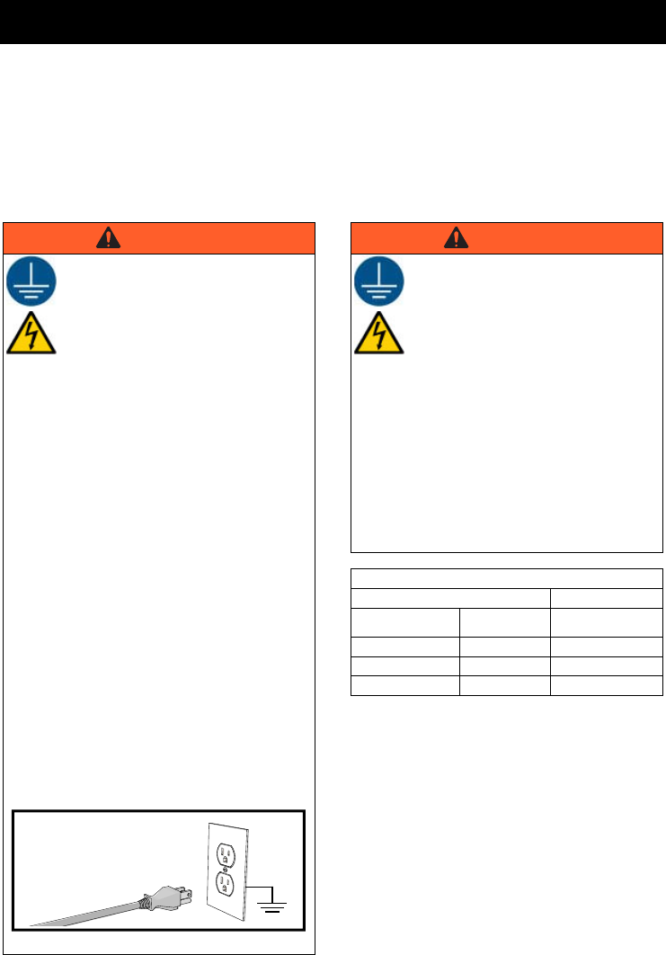
WARNING
GROUNDING INSTRUCTIONS
This product must be grounded. In the
event of an electrical short circuit,
grounding reduces the risk of electric
shock by providing an escape wire for
the electric current. This product is
equipped with a cord having a
grounding wire with an appropriate
grounding plug. The plug must be
plugged into an outlet that is properly
installed and grounded in accordance
with all local codes and ordinances.
•
Improper installation of the grounding plug
is able to result in a risk of electric shock.
•
When repair or replacement of the cord or
plug is required, do not connect the
grounding wire to either flat blade terminal.
•
The wire with insulation having an outer
surface that is green with or without yellow
stripes is the grounding wire.
•
Check with a qualified electrician or
serviceman when the grounding
instructions are not completely understood,
or when in doubt as to whether the product
is properly grounded.
•
Do not modify the plug provided; if it does
not fit the outlet, have the proper outlet
installed by a qualified electrician.
•
This product is for use on a nominal 120V
circuit and has a grounding plug similar to
the plug illustrated in the figures.
•
Only connect the product to an outlet having
the same configuration as the plug.
•
Do not use an adapter with this product.
ti3509b
WARNING
Extension Cords:
•
Use only a 3-wire extension cord
that has a grounding plug and a
grounding receptacle that accepts
the plug on the product.
•
An undersized cord results in a
drop in line voltage and loss of
power and overheating.When in
doubt use the next heavier gauge.
The smaller the gauge number the
heavier the cord.
•
When using the sprayer outdoors, use an
extension cord suitable for outdoor use.
•
Make sure your extension cord is not
damaged. When using an extension cord, be
sure to use a cord heavy enough to carry the
current that your sprayer draws. See chart for
appropriate sizes and lengths:
Extension Cord
Conductor Size Length
AWG (American
Wire Gauge)
Metric Maximum
18 1.0 mm250 ft (15 m)
16 1.5 mm2100 ft (30 m)
14 2.5 mm2200 ft (61 m)
Important Safety Information
333394H 5
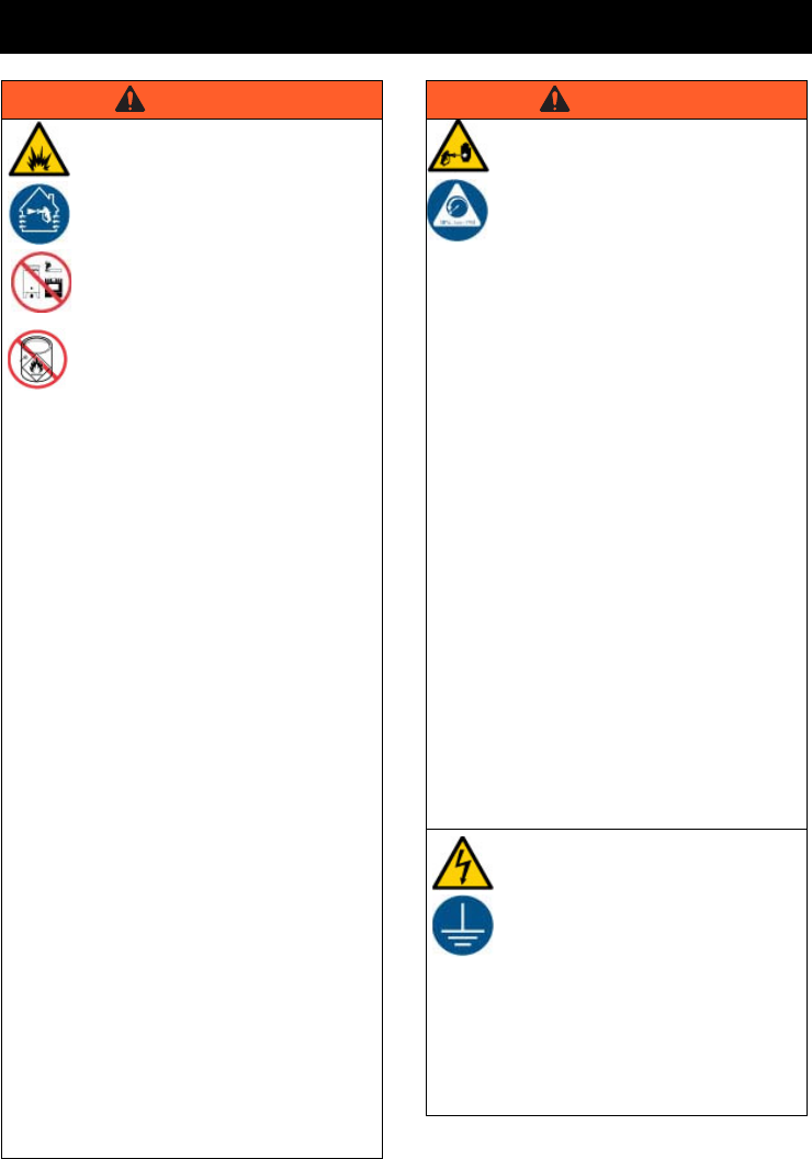
WARNING
FIRE AND EXPLOSION
HAZARD
Flammable fumes, such as solvent
and paint fumes, in work area can
ignite or explode. To help prevent fire
and explosion:
•
Sprayer generates sparks. Do not
spray or flush with flammable
liquids.
•
Use only
non-flammable or
water-based materials, or
non-flammable paint thinners.
•
Keep spray area well-ventilated.
Keep a good supply of fresh air
moving through the area.
•
When spraying oil-based material, use
outdoors or in a well-ventilated indoor area
with a flow of fresh air.
•
Do not spray or flush with combustible
materials near an open flame or sources of
ignition.
•
Paint or solvent flowing through the
equipment is able to result in static
electricity. Static electricity creates a risk of
fire or explosion in the presence of paint or
solvent fumes.
•
Keep sprayer at least 10 in. (25 cm) away
from objects while spraying or flushing.
•
Verify all containers and collection systems
are grounded to prevent static discharge.
•
Connect to a grounded outlet and use
grounded extension cords. Do not use a 3 to
2 adapter.
•
Do not use paints or solvents containing
halogenated hydrocarbons.
•
Do not smoke in the spray area.
•
Do not operate light switches, engines, or
similar spark producing products in the
spray area.
•
Keep area clean and free of paint or
solvent containers, rags, and other
flammable materials.
•
Know the contents of the paints and
solvents being sprayed. Read all Material
Safety Data Sheets (MSDS) and container
labels provided with the paints and
solvents. Follow the paint and solvents
manufacturer’s safety instructions.
•
Fire extinguisher equipment shall be
present and working.
SKIN INJECTION HAZARD
High-pressure spray is able to inject
toxins into the body and cause serious
bodily injury. In the event that injection
occurs, get immediate surgical
treatment.
•
Do not aim the sprayer at, or spray any
person or animal.
•
Keep hands and other body parts away
from the discharge. For example, do not
try to stop leaks with any part of the body.
•
Disconnect power when not spraying.
•
Always use the spray tip guard. Do not
spray without spray tip guard in place.
•
Use caution when cleaning and changing
spray tips. In the case where the spray tip
clogs while spraying, follow the
Pressure
Relief Procedure
, page 14 for relieving
the pressure before removing the spray tip
to clean.
•
Do not leave the unit energized or under
pressure while unattended. When the unit is
not in use, unplug the sprayer and follow the
Pressure Relief Procedure
, page 14.
•Check parts for signs of damage.
Replace any damaged parts.
•This system is capable of producing 2000
psi. Use replacement parts or
accessories that are rated a minimum of
2000 psi.
•Do not carry the unit with a finger on the
trigger.
•Verify that all connections are secure
before operating the unit.
•Know how to stop the unit and bleed
pressure quickly. Be thoroughly familiar
with the controls.
ELECTRIC SHOCK HAZARD
This equipment must be grounded.
Improper grounding, setup, or usage
of the system can cause electric
shock.
•
Turn off and disconnect power cord before
servicing equipment.
•
Connect only to grounded electrical outlets.
•
Use only 3-wire extension cords.
•
Ensure ground prongs are intact on power
and extension cords.
•
Do not expose to rain or wet conditions.
Store indoors.
WARNING
Important Safety Information
6333394H
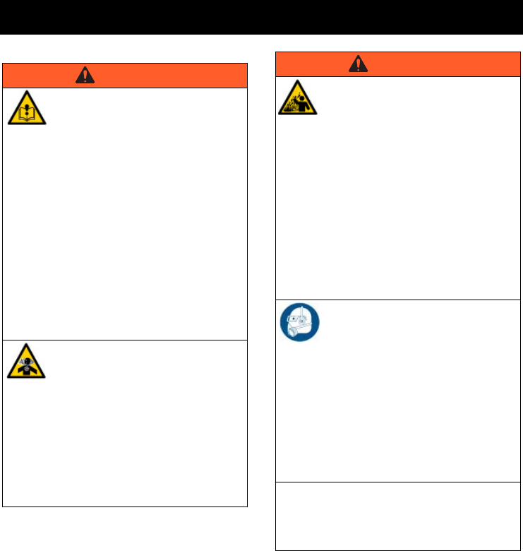
WARNING
EQUIPMENT MISUSE HAZARD
Misuse can cause death or serious
injury.
•
Always wear appropriate gloves, eye
protection, and a respirator or mask when
painting.
•
Do not operate or spray near children. Keep
children away from equipment at all times.
•
Do not overreach or stand on an unstable
support. Keep effective footing and balance
at all times.
•
Stay alert and watch what you are doing.
•
Do not operate the unit when fatigued or
under the influence of drugs or alcohol.
•
Use only in dry locations. Do not expose to
water or rain.
•
Use in well-lit areas.
•
Do not spray outdoors on windy days.
TOXIC FLUID OR FUMES
HAZARD
Toxic fluids or fumes can cause
serious injury or death if splashed in
the eyes or on skin, inhaled, or
swallowed.
•
Read MSDS’s to know the specific hazards
of the fluids you are using.
•
Store hazardous fluid in approved
containers, and dispose of it according to
applicable guidelines.
PRESSURIZED ALUMINUM
PARTS HAZARD
Use of fluids that are incompatible with
aluminum in pressurized equipment
can cause serious chemical reaction
and equipment rupture. Failure to
follow this warning can result in death,
serious injury, or property damage.
•
Do not use 1,1,1-trichloroethane,
methylene chloride, other halogenated
hydrocarbon solvents or fluids containing
such solvents.
•
Do not use chlorine bleach.
•
Many other fluids may contain chemicals
that can react with aluminum. Contact your
material supplier for compatibility.
PERSONAL PROTECTIVE
EQUIPMENT
Wear appropriate protective equipment when
in the work area to help prevent serious injury,
including eye injury, hearing loss, inhalation of
toxic fumes, and burns. This protective
equipment includes but is not limited to:
•
Protective eye wear, and hearing
protection.
•
Respirators, protective clothing, and gloves
as recommended by the fluid and solvent
manufacturer.
CALIFORNIA PROPOSITION 65
This product contains a chemical known to the
State of California to cause cancer, birth defects
or other reproductive harm. Wash hands after
handling.
WARNING
Component Identification
333394H 7
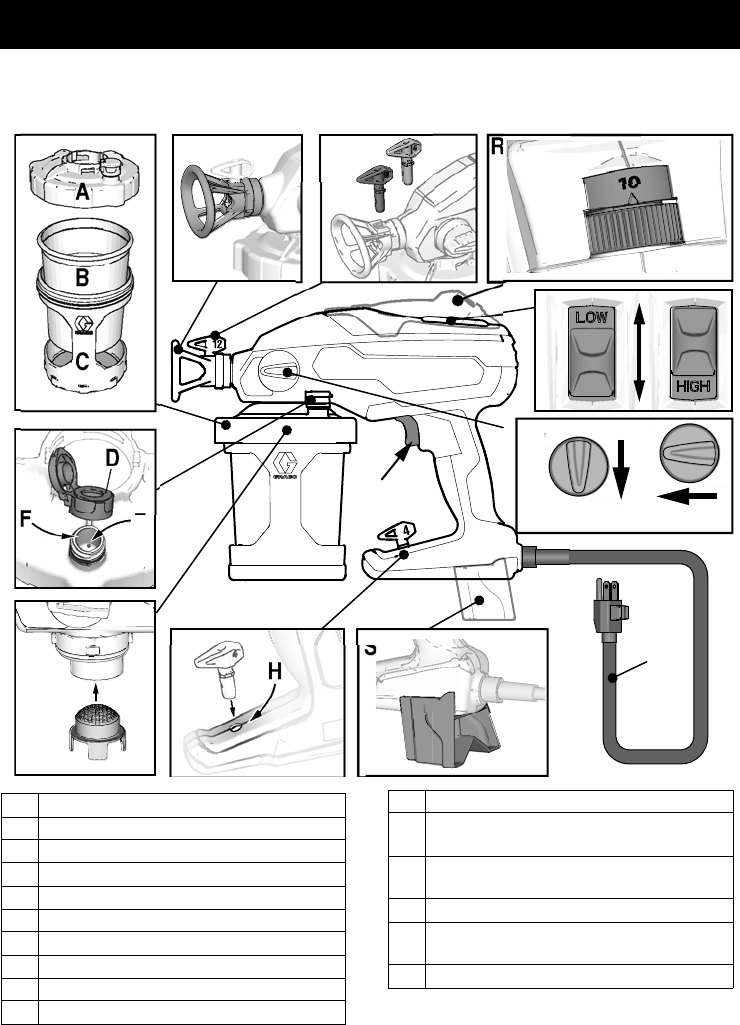
Component Identification
A
B
C
D
E
F
GH
N
L
K
S
R
Spray
J
M
ti25736a
P
Prime Pump
A Cup Cover
B FlexLiner
C Cup Support
D VacuValve Cap
E VacuValve Air Hole
F VacuValve Reservoir
GStrainer
H Spray Tip Holder
J Prime Pump/Spray Knob
K Power Cord
L Sprayer Trigger
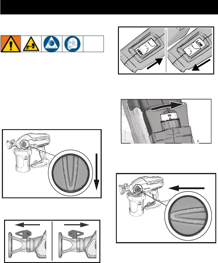
M Dual Speed Control, HIGH/LOW
Switch (DS and DSP models only)
N Spray Tip, Black (12-inch pattern)
Spray Tip, Gray (4-inch pattern)
P Spray Tip Guard
R Variable Speed Control (VSP models
only)
S Kickstand
Start Up
8333394H
Start Up
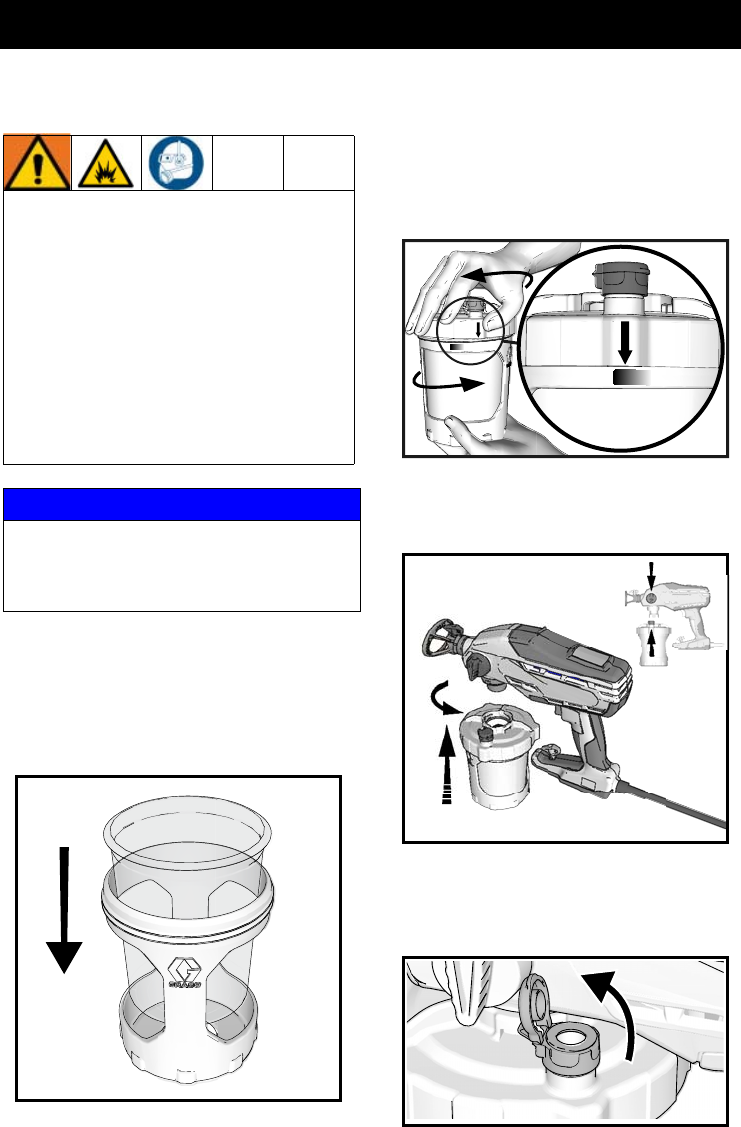
Starting a New Job
If you are using the sprayer for the very first
time, see Flushing a New Sprayer, page 20.
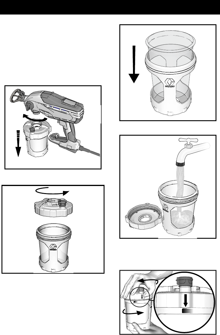
1. Install FlexLiner in the cup support.
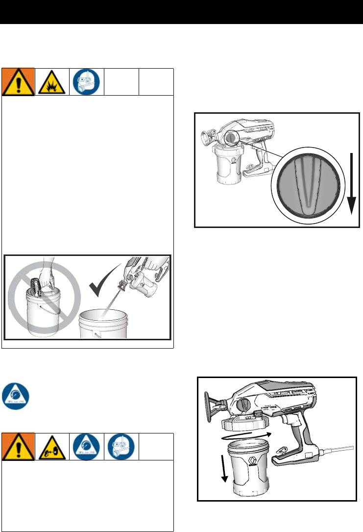
2. Fill FlexLiner with material. Securely
tighten cup cover onto cup support.
Tighten so the arrow on the cup cover is
within range of the indicator on the cup
support.
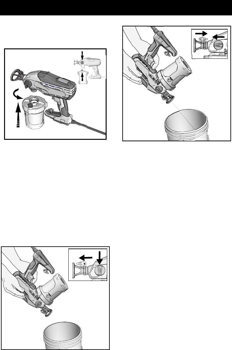
3. Align VacuValve on cup cover with
Prime Pump/Spray knob. Push cup
assembly onto sprayer and twist to lock.
4. The VacuValve is an important part of
your new sprayer. It is used to evacuate
the air out of the FlexLiner. Open
VacuValve cap.
Use only water-based or oil-based
(mineral spirit-type) materials with a
flash point greater than 100° F (38° C).
Do not use materials which state
“FLAMMABLE” on the packaging. For
more information about your material,
request MSDS from distributor or retailer.
When spraying oil-based material, use
outdoors or in a well-ventilated indoor
area with a flow of fresh air.
Keep spray area well-ventilated. Keep
a good supply of fresh air moving through
the area.
NOTICE
Your sprayer is
NOT
compatible with harsh
cleaners such as chlorine bleach. Using
these cleaners will cause damage to the
sprayer.
ti23361a
ti24279a
ti23258b
ti23343a
Start Up
333394H 9
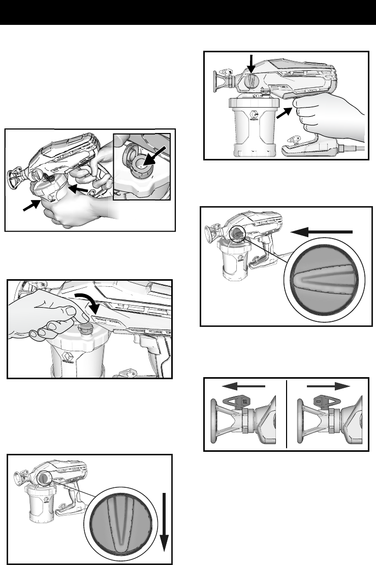
5. Tilt the sprayer so the VacuValve is the
highest point, causing any air in the
FlexLiner to rise to the VacuValve.
Gently squeeze the FlexLiner to
evacuate all air through the VacuValve
air hole. Once you see material enter the
VacuValve reservoir, all air should be
evacuated from the FlexLiner.
6. Stop squeezing the FlexLiner and snap
the VacuValve cap closed. You will hear
the cap click when it is closed properly.
7. Plug sprayer into power source.
8. Turn Prime Pump/Spray knob down to
Prime Pump position. To fill sprayer with
fluid, point sprayer into a waste area and
hold the trigger in for 5–10 seconds.
9. Turn Prime Pump/Spray knob forward to
spray position.
10. Make certain spray tip is in the spray
position.
11. You are now ready to spray.
NOTE: For best results; to evacuate all
material from the FlexLiner when the material
is nearly gone, gently squeeze the bottom of
the FlexLiner to push the last of the material
up to the cup lid.
ti23345a
ti23355a
ti23285a
Prime Pump
ti23354a
ti23288a
Spray
ti23290a
SPRAY UNCLOG
Start Up
10 333394H
If sprayer does not spray, try one of
the steps below:
•Make certain there is only one FlexLiner
in cup support. It is possible for two liners
to nest tightly together and appear as
only one.
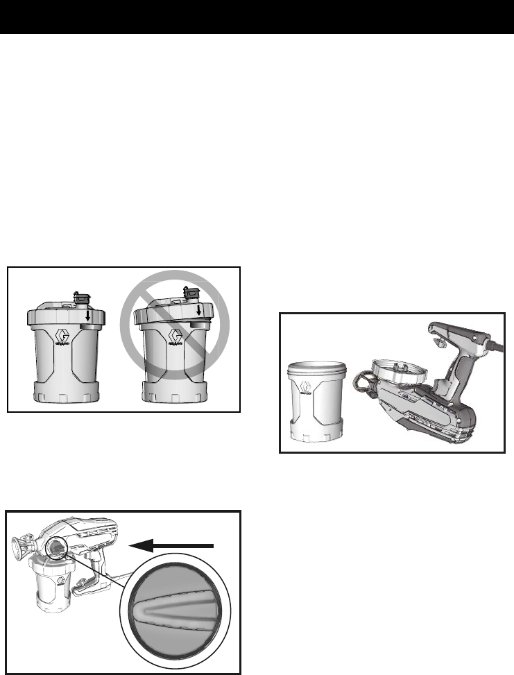
•Make certain the cup cover is properly
threaded to the cup support. If threads
are visible below the cup cover when
tight, then the cover is cross-threaded.
Fully remove the cup cover and reinstall
to the cup support so no threads are
visible when tight.
•Repeat steps 2 – 6 on pages 8 – 9 to
ensure all the air is evacuated from the
FlexLiner.
•Make certain the Prime Pump/Spray
knob is in the Spray position.
•If sprayer still does not spray, perform
steps10 and 11 on page 21. If material
sprays while upside down there is air in
the cup. Repeat steps above.
Refilling FlexLiner
If sprayer runs out of paint simply separate
the cup support from the cup cover/sprayer
and refill the FlexLiner.
1. Unplug sprayer from power source.
2. Separate the cup support from the
cup
cover/sprayer.
Set the sprayer upside
down on a flat surface. This will keep the
wet paint in the cup cover.
3. Follow steps 2 - 11 in Starting a New
Job, page 8 procedure.
ti24454a
ti23288a
Spray
ti23369a
How to Spray
333394H 11
How to Spray
Take a few moments prior to spraying and
review these simple tips to ensure your
spraying project is a success.
Dual Speed Control
(Not available on all units)
The dual speed control feature allows you to
slow down or speed up when spraying.
•Turn the dual speed control to LOW to
slow down the speed of application when
first learning to spray or when spraying
small items that require more control.
•The LOW setting delivers more control
and will reduce overspray when spraying
thinner materials such as stain.
•Turn the dual speed control to HIGH
when you want to get to job done fast and
when spraying large surfaces.
•To reduce overspray, always spray at
lowest speed that results in an
acceptable spray pattern.
Variable Speed Control
(Not available on all units)
The variable speed control feature allows you
infinite speed control to slow down or speed
up to best suit your material and project.
•Turn the variable speed control to lower
speed settings to slow down the speed of
application when first learning to spray or
when spraying small items that require
more control.
•The lower speed settings deliver more
control and will reduce overspray when
spraying thinner materials such as stain.
•Turn the variable speed control to higher
speed settings when you want to get the
job done fast and when spraying large
surfaces.
•To reduce overspray, always start at
lowest speed setting and increase speed
to the minimum setting that results in an
acceptable spray pattern.
Spray Techniques
Use a piece of scrap cardboard to practice
these basic spraying techniques before you
begin spraying the surface.
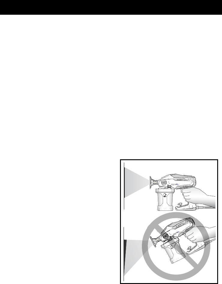
•Hold sprayer 10 in. (25 cm) from surface
and aim straight at surface. Tilting the
sprayer to direct the spray angle causes
an uneven finish.
•Flex wrist to keep sprayer pointed
straight. Fanning sprayer to direct spray
at angle causes uneven finish.
NOTE: How fast you move the sprayer will
affect spray application. If material is
pulsating, you are moving too fast. If material
drips, you are moving too slow. See
Troubleshooting, page 26.
ti23374a
EVEN
FINISH
10 in.
(25 cm)
UNEVEN
FINISH
THICK
THIN
How to Spray
12 333394H
Triggering Sprayer
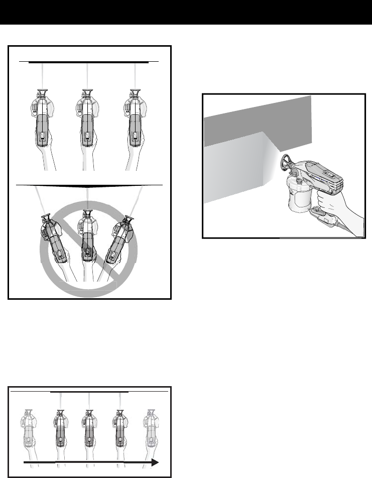
Pull trigger after starting stroke. Release
trigger before end of stroke. Sprayer must be
moving when trigger is pulled and released.
Aiming Sprayer
Aim sprayer at bottom edge of previous
stroke, overlapping each stroke by half.
Rotating the spray tip guard changes the
pattern to either the vertical or horizontal
orientations.
When spraying vertical corners turn spray tip
guard to the horizontal orientation and move
sprayer up and down.
ti23375a
EVEN FINISH
THICK THINTHIN
ti23376a
ti23378a
How to Spray
333394H 13
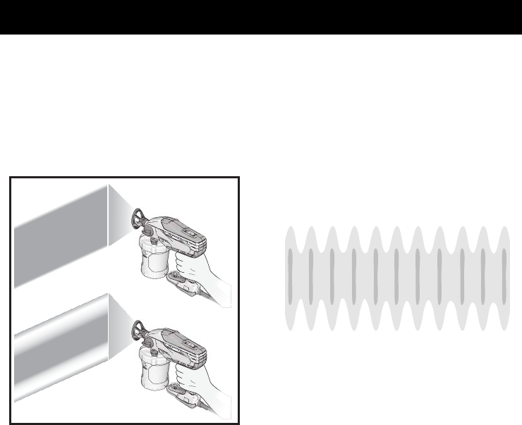
Spray Pattern Quality
A good spray pattern is evenly distributed as
it hits the surface. If tails persist, material may
need to be thinned.
If material needs to be thinned follow
manufacturers recommendations.
If you see pulsations in the pattern, try the
following:
•On the dual speed models turn the dual
speed control to HIGH
•On the variable speed models turn the
variable speed control to higher setting
•Slow down your speed of movement
•Hold sprayer farther away from surface
•Switch to black (12") spray tip
ti23382a
GOOD PATTERN
BAD PATTERN
TAILS
TAILS
Spray Pattern is Pulsating
Cleanup
14 333394H
Cleanup
Pressure Relief Procedure
Follow the Pressure Relief
Procedure whenever you see this
symbol.
1. Disconnect power (unplug power cord).
2. Turn Prime Pump/Spray Knob down to
PRIME PUMP position to relieve
pressure.
Cleaning Sprayer
Cleaning your sprayer properly and after every
spray job is of the utmost importance! Proper
care and maintenance will make your paint
sprayer last and work for you trouble free.
1. Turn Prime Pump/Spray knob to Prime
Pump to relieve pressure.
2. Separate the cup support with FlexLiner
from the cup cover/sprayer.
Use only water-based or oil-based
(mineral spirit-type) materials with
flash point greater than 100° F (38° C).
Do not use materials which state
“FLAMMABLE” on the packaging. For
more information about your material,
request MSDS from distributor or retailer.
Clean in a well-ventilated area. Keep a
good supply of fresh air moving through
the area.
To avoid serious injury or damage to
equipment, do not expose the sprayer
electronics to cleaning fluids. Keep
sprayer at least 10 in. (25 cm) above the
rim of the container when cleaning.
This sprayer builds up an internal
pressure of 2000 psi (14 MPa, 138 bar)
during use. Follow this Pressure Relief
Procedure whenever you stop spraying
and before cleaning, checking, servicing,
or transporting equipment to prevent
serious injury.
ti23408a
ti23285a
Prime Pump
ti23385a
Cleanup
333394H 15
3. Set the sprayer upside down on a flat
surface. This will keep the wet paint in
the cup cover. Return excess material to
original container. Hold the FlexLiner in
place when pouring.
4. You can either dispose of the used
FlexLiner and install a new FlexLiner or
clean a used FlexLiner.
5. To clean the sprayer, fill FlexLiner
approximately half-full with appropriate
cleaning fluid (water or mineral spirits).
6. Securely tighten cup cover onto cup
support.
7. To clean the cup cover and strainer,
secure the cup assembly to the sprayer
and shake the entire sprayer for ten
seconds.
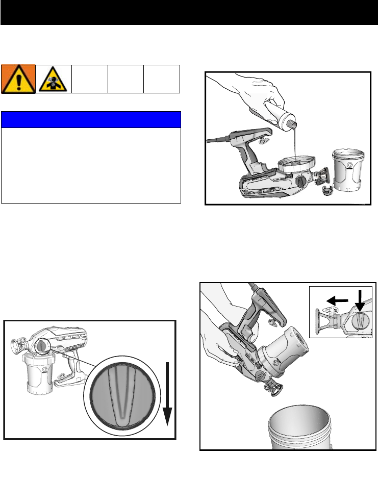
8. Make certain the Prime Pump/Spray
knob is in the Prime Pump position
(pointed down). On models with a dual
speed control switch, set speed control
to HIGH. On variable speed models set
speed control to 10.
9. Turn the sprayer upside down and point
the sprayer into a waste pail. Pull the
trigger for ten seconds.
10. Turn Prime Pump/Spray knob forward to
SPRAY position. Reverse spray tip to
UNCLOG position.
11. While holding the sprayer upside down
point the sprayer into a waste pail. Pull
the trigger for five seconds. Release the
trigger.
12. If second spray tip was used, remove
cleaned spray tip from spray tip guard
and install second spray tip. See
Installing Spray Tips, page 18. Repeat
steps 10 and 11 to clean second spray
tip.
ti23387a
ti23383a
ti23384a
ti23388a
Cleanup
16 333394H
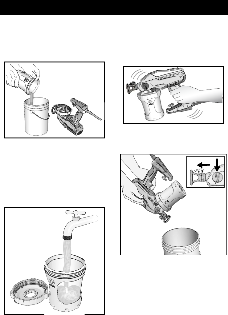
13. Remove cup assembly and discard used
fluid. Dispose of used cleaning fluid
properly.
14. Replace cleaning fluid and repeat steps
1- 13 until spray output is clean.
IMPORTANT! For best results, do not spray
more than one cup of water through the tip
while cleaning. If more flushing is needed,
remove the tip from the sprayer to avoid
excessive wear.
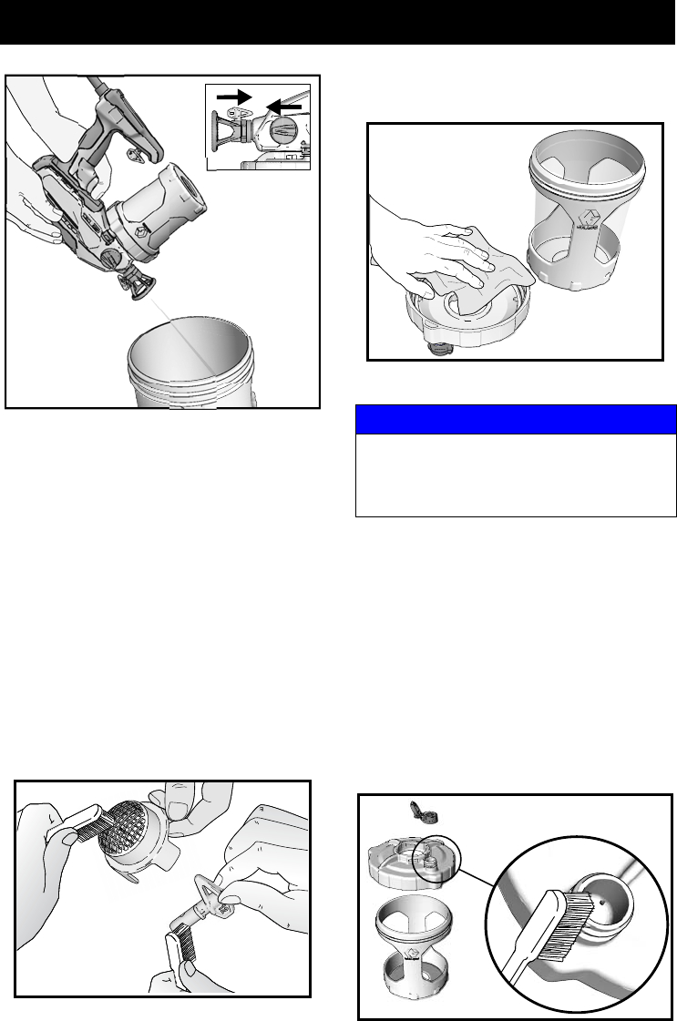
15. Remove spray tip and strainer, see
Remove Spray Tip, page 18. Clean with
appropriate cleaning fluid (water or
mineral spirits). A soft brush can be used
to loosen and remove dried material if
needed.
16. Use a soft cloth to clean the cup support
and cup cover.
Cleaning VacuValve
The VacuValve is an important part of your
sprayer and it should be cleaned after every
use.
1. Remove VacuValve cap from cup cover
and clean it.
2. Clean VacuValve reservoir in lid.
3. Clean VacuValve air hole. If VacuValve
air hole becomes clogged, use a paper
clip to clean the hole.
ti23389a
ti23404a
NOTICE
The spray tip guard is permanently
attached to the sprayer. Removal for
cleaning is not necessary and will result in
damage to the sprayer.
ti23372a
ti23406a
Storage
333394H 17
Storage
Pump Armor fluid protects the sprayer while
in storage. It helps protect sprayer against
freezing and corrosion when not in use.
1. Clean the sprayer and cup assembly.
See Cleanup, page 14.
2. Turn Prime Pump/Spray knob down to
the Prime Pump position. Remove cup
support and FlexLiner. Make certain that
VacuValve cap is closed.
3. Separate the cup support with FlexLiner
from the cup cover/sprayer. Set the
sprayer upside down on a flat surface.
4. Remove strainer from pump opening.
5. With the sprayer upside-down pour
approximately 2 oz. (60 ml) Pump Armor
into pump opening.
6. Install strainer into pump opening.
7. With sprayer upside-down attach cup
support with FlexLiner to sprayer.
8. Holding sprayer upside-down over a
waste container, pull sprayer trigger for
three seconds.
9. Turn Prime Pump/Spray knob forward to
spray position. Remove cup assembly
and pour any remaining Pump Armour
back into Pump Armor bottle. Replace
child-resistant cap and tighten securely
for storage.
10. Store sprayer indoors in a cool, dry
place. Store in an upright position
only. Never store sprayer with material
in the cup.
NOTICE
Failure to store sprayer with Pump Armor
will result in operational problems the next
time you spray. Always circulate Pump
Armor through the sprayer after cleaning.
Water or solvents other than mineral
spirits left in the sprayer will corrode
and damage the pump.
ti23285a
Prime Pump
ti23707b
ti23388a
Common Procedures
18 333394H
Common Procedures
Installing Spray Tips
Two spray tips are available for use with this
sprayer. The black tip produces a 12-inch
wide spray pattern. The gray tip produces a
4-inch wide spray pattern.
Either spray tip may be used to spray mate-
rials that are recommended to be sprayed
with a 0.015 tip size. See material container
for spray tip size recommendations.
Remove Spray Tip
1. Perform Pressure Relief Procedure,
page 14.
2. Rotate the spray tip 90 degrees from
either the SPRAY or UNCLOG position.
3. Pull the spray tip straight out of the spray
tip guard.
Install Spray Tip
1. While holding the spray tip 90 degrees
from either the SPRAY or UNCLOG
position, align spray tip locking tab with
the locking tab slot in the spray tip guard.
2. Push the spray tip all the way into the
spray tip guard.
3. Rotate the spray tip to the SPRAY
position.
NOTE: Make certain spray tip locking tab is
pushed all the way into the slot in the spray tip
guard. You should not be able to remove the
spray tip from the spray tip guard when it is in
the Spray or Unclog positions.
NOTE: If the locking tab slot in the spray tip
guard is blocked, preventing installation of
the spray tip, rotate the spray tip guard until it
is visually aligned with the internal hole, then
install the spray tip.
•
Spray tips wear with use and abrasive
paint and need periodic replacement.
•If the spray pattern is poor, you may have
a worn spray tip. Replace spray tip. See
Spray Pattern Diagnostics, page 28.
Do not put your hand in front of the spray tip.
ti23563a
LOCKING TAB SLOT
LOCKING
REMOVE
SPRAY TIP
TAB
ROTATE
SPRAY TIP 90
o
NOTICE
The spray tip guard is permanently
attached to the sprayer. Removal for
cleaning is not necessary and will result in
damage to the sprayer.
NOTICE
Spray tips must be cleaned or stored in
appropriate cleaning fluid (water or mineral
spirits) immediately after use to ensure
material is not allowed to dry in spray tip.
Failure to do so will result in damage to the
spray tip. See Cleanup, page 14.
Common Procedures
333394H 19
Unclogging Spray Tip
In the event that particles or debris clog the
spray tip, this sprayer is designed with a
reversible spray tip that quickly and easily
clears the particles without disassembling the
sprayer.
1. Perform Pressure Relief Procedure,
page 14.
2. To unclog spray tip, turn Prime
Pump/Spray knob down to Prime Pump
position.
3. Reverse spray tip to UNCLOG position.
4. Dual speed models:
Move speed control switch to HIGH
setting.
5. Variable speed models:
Set speed control to 10.
6. Aim sprayer at waste area, turn Prime
Pump/Spray knob forward to spray
position. Pull trigger to clear clog.
7.
Turn Prime Pump/Spray knob down to
Prime position.
Rotate spray tip back to
SPRAY position. Turn Prime
Pump/Spray knob forward to SPRAY
position, and resume spraying.
8. If spray tip is still clogged, you may have
to repeat steps 2 - 7, or replace with new
spray tip assembly. See Installing
Spray Tips, page 18.
ti23285a
Prime Pump
ti23290a
SPRAY UNCLOG
ti23359a
10
ti25737a
ti23288a
Spray
Common Procedures
20 333394H
Flushing a New Sprayer
This sprayer arrives from the factory with a
small amount of test material in the system.
It is important that you flush this material
from the sprayer before using it for the
first time.
1. Remove cup assembly from the sprayer
by turning and pulling down.
2. Unscrew cup cover from the cup support.
3. Make certain FlexLiner is in the cup
support.
4. Fill FlexLiner with water.
5. Securely tighten cup cover onto cup
support. Tighten so the arrow on the cup
cover is within range of the indicator on
the cup support.
ti23249b
ti23676a
ti23361a
ti23383a
ti24279a
Common Procedures
333394H 21
6. Align VacuValve on cup cover with
Prime Pump/Spray knob. Push cup
assembly onto sprayer and twist to lock.
7. Plug sprayer into power source.
8. Make certain the Prime Pump/Spray
knob is in the Prime Pump position
(pointed down). On models with a dual
speed control switch, set speed control
to HIGH. On variable speed models set
speed control to 10.
9. Turn the sprayer upside down and point
the sprayer into a waste pail. Pull the
trigger for three seconds.
10. Turn Prime Pump/Spray knob forward to
SPRAY position. Rotate spray tip 180
degrees to UNCLOG position.
11. While holding the sprayer upside down
point the sprayer into a waste pail. Pull
the trigger for three seconds.
IMPORTANT! For best results, do not spray
more than one cup of water through the tip
while cleaning. If more flushing is needed,
remove the tip from the sprayer to avoid
excessive wear.
12. Sprayer is now flushed and ready for
use. See Start Up, page 8.
IMPORTANT! The motor has a built-in
feature to protect itself from overuse. If the
motor stops, the thermal switch has tripped.
Do not return sprayer to store. The motor
will operate normally after cooling for 20-30
minutes.
ti23258b
ti23388a
ti23389a

Replacement Parts
22 333394H
Replacement Parts
Models 16Y385, 16Y386, 17A466
8
19
19
20
24
13a
13b
12
7
8
51
10
2
6
3
4
9
18
17
16
14
15
22
ti23460a
ti23568a
26

Replacement Parts
333394H 23
Parts List- Models 16Y385, 16Y386, 17A466
Ref. If you have this
model sprayer
Order
Part
Number
Description
1 Kit, pump
16Y385, 17A466 17A217 Complete pump assembly includes 2, 3, 4, 5, 6, 7, 8
16Y385, 17A466 17A218 Pump housing includes 2, 3, 5
16Y386 17B415 Complete pump assembly includes 2, 3, 4, 5, 6, 7, 8
16Y386 17B416 Pump housing includes 2, 3, 5
2 All models 16Y425 O-ring
3 All models 16W849 Strainer
4 All models 17A219 Kit, needle assembly includes 5 and spray tip 17A222
5 All models 17A220 Kit, pump outlet
6 All models 17A402 Prime Pump/Spray valve
7 All models 17A221 Kit, Prime Pump/Spray knob includes qty. 1 of ref. 8
8 All models 119236 Screw, T-15 (torque 8-10 in-lb / 0.9-1.1 N•m)
9 All models 17A223 Spray tips, (black/12-inch pattern, gray/4-inch pattern)
10 All models 16X880 Reciprocator assembly
12 Control, electronic includes motor, power cord and switch
16Y385 17A224 Single speed, 120 V (not shown)
16Y386, 17A466 17B653 Dual speed, 120 V
13a 16Y386, 17A466 16X868 Switch, dual speed control
13b 16Y385 16X869 Plug
14 All models 16W846 Support, 32 oz. cup
15 All models 17A226 Kit, 32oz., FlexLiner (3-pack)
16 All models 17B636 Cover, cup
17 All models 115719 O-ring
18 All models 16X806 VacuValve cap
19 16Y385, 17A466 17A227 Kit, enclosure blue includes qty. 13 of ref. 8,
16Y386 17A649 Kit, enclosure gray includes qty. 13 of ref. 8,
20 All models 16Y680 Label, USA
22 All models 16Y678 Label, control
23 All models 16Y636 Label, warning and model number, side (not shown)
24 Label, brand
16Y385 16Y677 TrueCoat 360
16Y386 17A473 TrueCoat 360 DSP
17A466 16Y679 TrueCoat 360 DS
25 All models 17A198 Label, warning, cord (not shown)
26 16Y386 17C468 Case, storage
All models 17F518 Kit, 42 oz. cup (not shown)
- - - 243104 Pump Armor, not shipped with sprayer 32 oz (not shown)
Replacement Danger and Warning labels, tags, and cards are available at no cost.
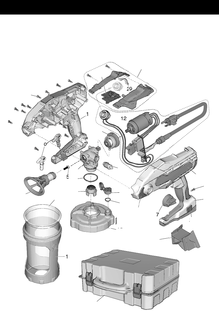
Replacement Parts
24 333394H
Replacement Parts
Model 17D889
8
19
29
19
20
24
12
13
7
8
5
1
10
2
6
3
4
9
18
17
16
14
15
22
28
26
27
ti25730a

Replacement Parts
333394H 25
Parts List- Model 17D889
Ref. If you have this
model sprayer
Order
Part
Number
Description
1 Kit, pump
17D889 17B415 Complete pump assembly includes 2, 3, 4, 5, 6, 7, 8
17D889 17B416 Pump housing includes 2, 3, 5
2 All models 16Y425 O-ring
3 All models 16W849 Strainer
4 All models 17A219 Kit, needle assembly includes 5 and spray tip 17A222
5 All models 17A220 Kit, pump outlet
6 All models 17A402 Prime Pump/Spray valve
7 All models 17A221 Kit, Prime Pump/Spray knob includes qty. 1 of ref. 8
8 All models 119236 Screw, T-15 (torque 8-10 in-lb / 0.9-1.1 N•m)
9 All models 17A223 Spray tips, (black/12-inch pattern, gray/4-inch pattern)
10 All models 16X880 Reciprocator assembly
12 17D889 17F068 Control, electronic includes motor, power cord and switch
Variable speed, 120 V
13 17D889 17D844 Adapter, variable speed control
14 17D889 17D850 Support, cup, 42 oz.
15 17D889 17F005 Kit, 42 oz., FlexLiner (3-pack)
16 All models 17B636 Cover, cup
17 All models 115719 O-ring
18 All models 16X806 VacuValve cap
19 17D889 17A649 Kit, enclosure gray includes qty. 13 of ref. 8
20 All models 16Y680 Label, USA
22 All models 16Y678 Label, control
23 All models 16Y636 Label, warning and model number, side (not shown)
24 17D889 17F154 Label, brand, TrueCoat 360 VSP
25 All models 17A198 Label, warning, cord (not shown)
26 17D889 17C468 Case, storage
27 17D889 17F069 Kit, enclosure, variable speed includes sight glass,
includes 13, 29, qty. 2 of ref 8
28 17D889 17F364 Kickstand
29 17D889 17D843 Sight glass
All models 17F518 Kit, 42 oz. cup includes 14, 15, 28
- - - 243104 Pump Armor, not shipped with sprayer 32 oz (not shown)
Replacement Danger and Warning labels, tags, and cards are available at no cost.
Troubleshooting
26 333394H
Troubleshooting
Check everything in this Troubleshooting
Table before you bring the sprayer to an
authorized service center.
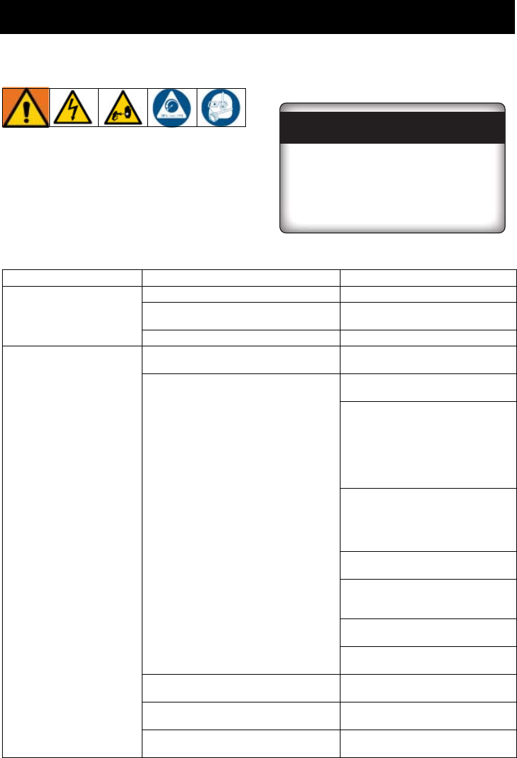
Sprayer Diagnostics
ti24021a
Have a Question?
Call toll-free:
1-888-541-9788
Or visit us at:
www.paintsprayersbygraco.com
Problem Cause Solution
Sprayer makes no sound
when trigger is pulled
Power supply. Verify power to sprayer.
Motor has overheated. Wait 20-30 minutes for motor to
cool.
Electronic control failure. Replace electronic control.
Sprayer makes sound but
no material is sprayed
when trigger is pulled
Sprayer is not primed. Prime the pump. See Starting a
New Job, page 8.
Make certain there is only one
FlexLiner in the cup support.
Make certain the cup cover is
properly threaded to the cup
support. If threads are visible
below the cup cover when tight,
fully remove and reinstall to the
cup support so no threads are
visible when tight.
Make certain the cup cover is
tightened to cup support so the
arrow on cup cover is within
range of indicator on cup
support.
Make certain the cup assembly is
properly locked on the sprayer.
Make certain all the air is out of
the FlexLiner and the VacuValve
is properly closed.
Clean VacuValve reservoir and
air hole. See , page 16.
Clean Sprayer. See Cleanup,
page 14.
Prime Pump/Spray knob is in PRIME
PUMP position.
Turn Prime Pump/Spray knob
forward to SPRAY position.
Spray tip is not in SPRAY position. Turn spray tip to SPRAY
position.
Spray tip is clogged. See Unclogging Spray Tip,
page 19.

Troubleshooting
333394H 27
Sprayer makes sound
but no material is
sprayed when trigger is
pulled (cont’d)
Speed control is set too low. On models with a dual speed
control switch, set speed control
switch to HIGH. On variable
speed models, increase speed
until unit sprays.
No or low material in material cup. Refill FlexLiner with material and
prime the pump. See Refilling
FlexLiner, page 10.
Sprayer sprays with poor
results
Spray tip is partially clogged. See Unclogging Spray Tip,
page 19
.
Spray tip is not in correct position Rotate spray tip to SPRAY
position.
Incorrect spray tip for application of
material.
Install different size spray tip.
See Installing Spray Tips, page
18.
Spray tip is worn or damaged Replace spray tip. See
Installing Spray Tips, page 18.
Material being sprayed is aerated
because it was shaken.
Do NOT shake material. Stir the
material or check the
manufacturer’s recommendation
for the material being sprayed.
Material being sprayed is too cold to
spray.
Warm material.
Paint leaks from sprayer
trigger area.
Pump has reached its maximum life. Replace pump.
Paint leaks out of the cup
threads.
Cup not properly seated. Make certain that there is only
one FlexLiner in cup support.
Make certain the cup cover is
properly threaded to the cup
support. If threads are visible
below the cup support when
tight, fully remove the cup cover
and reinstall to the cup support
so no threads are visible when
tight.
Make certain the cup cover is
tightened to the cup support so
the arrow on the cup cover is
within range of the indicator on
the cup support.
Avoid flexing or pushing on the
cup support when you evacuate
the air out of the FlexLiner.
Avoid pulling down on the
FlexLiner when you evacuate the
air out of the FlexLiner.
Make certain there is no damage
to the FlexLiner lip or the cup
cover gasket.
Make certain that the FlexLiner
lip and cup cover gasket is free of
debris and dried paint.
Replace FlexLiner.
Problem Cause Solution

Troubleshooting
28 333394H
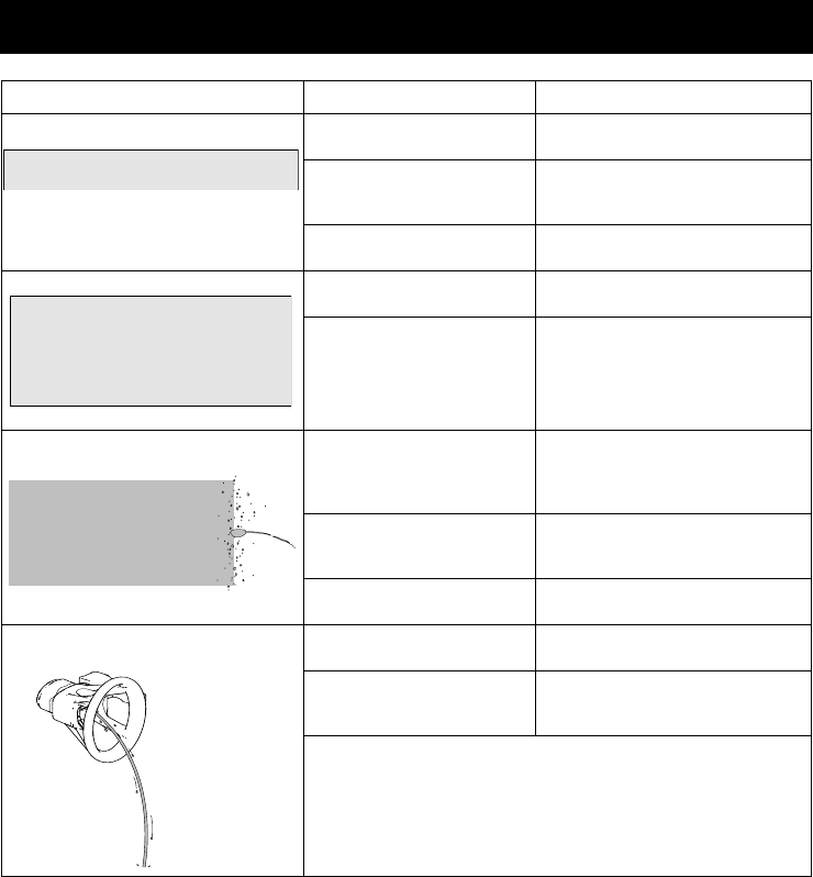
Spray Pattern Diagnostics
Problem Cause Solution
Spray pattern is pulsating: Operator is moving too
fast while spraying.
Slow speed of movement.
Spray tip is clogged. Unclog spray tip or clean spray
tip see Unclogging Spray Tip,
page 19.
Material difficult to
atomize.
On models with a dual speed
control switch, set speed control
to HIGH. On variable speed
models, increase speed until
desired pattern is achieved.
Hold sprayer farther away from
surface.
Switch to black (12”) spray tip.
See Installing Spray Tips,
page 18.
Spray pattern has tails: Speed control is set too
low.
On models with a dual speed
control switch, set speed control
to HIGH. On variable speed
models, increase speed until
desired pattern is achieved.
Material may need to be
thinned.
Thin material follow paint
manufacturer’s
recommendations.
Incorrect spray tip for
application of material.
Install different size spray tip.
See Installing Spray Tips,
page 18.
Material not compatible
with sprayer.
Switch material.
Spray tip is worn or
damaged.
Replace spray tip. See
Installing Spray Tips, page 18.
Spray pattern has
dripping/sagging:
Operator is moving too
slowly while spraying.
Move sprayer faster while
spraying.
Sprayer is too close to
target surface.
Move sprayer away from
surface 10 in. (25 cm)
Holding trigger while
changing spray direction.
Release trigger when changing
directions.
Speed control switch is set
too high.
On models with a dual speed
control switch, set speed control
to LOW. On variable speed
models, decrease speed until
desired pattern is achieved.
Spray tip is worn or
damaged.
Replace spray tip. See
Installing Spray Tips, page 18.
ti15526a
Troubleshooting
333394H 29
Spray pattern is too narrow: Sprayer is too close to
target surface.
Move sprayer away from
surface 10 in. (25 cm)
Incorrect spray tip for
application of material.
Install different size spray tip.
See Installing Spray Tips,
page 18.
Spray tip is worn or
damaged.
Replace spray tip. See
Installing Spray Tips, page 18.
Spray pattern is too wide: Sprayer is too far away
from target surface.
Move sprayer closer to surface.
Incorrect spray tip for
application of material.
Install different size spray tip.
See Installing Spray Tips,
page 18.
Spray pattern “spits” at the end or
beginning:
Excess material has
accumulated on spray tip
guard assembly or spray
tip is partially clogged.
Clean spray tip guard. See
Unclogging Spray Tip, page
19.
Spray tip not inserted
completely into spray tip
guard.
See Installing Spray Tips,
page 18.
Spray tip is worn. Replace spray tip. See
Installing Spray Tips, page 18.
Spray tip continues to drip or ooze
material after trigger is released:
Spray tip is worn. Replace spray tip. See
Installing Spray Tips, page 18.
Spray tip not inserted
completely into spray tip
guard.
See Installing Spray Tips,
page 18.
If above solutions do not solve the problem, replace the
needle assembly.
Problem Cause Solution
ti15523a
ti15523a
ti15527a
ti15527a
ti15525a
ti15525a
ti15552a

Technical Data
30 333394H
Technical Data
Hand-Held Sprayer
U.S. Metric
Max Working Pressure
TrueCoat 360 1200 psi 8.3 MPa, 83 bar
TrueCoat 360 DS/DSP/VSP 1300 psi 9 MPa, 90 bar
Maximum Amperage 2.5 Amps 2.5 Amps
Weight
TrueCoat 360, 360 DS/DSP 3.5 lb (18 in.cord) 1.6 kg (45 cm cord)
TrueCoat 360 VSP 3.75 lb (18 in.cord) 1.7 kg (45 cm cord)
Dimensions:
Length (All models) 12.50 in. 31.75 cm
Width (All models) 5.25 in. 13.34 cm
Height 360, 360 DS/DSP 9.75 in. 24.77 cm
Height 360 VSP 11.8 in. 29.97 cm
Storage Temperature Range 32° to 113° F 0° to 45° C
Operating Temperature Range 40° to 90° F 4° to 32° C
Storage Humidity Range 0% to 95% relative
humidity,
non-condensing
0% to 95% relative humidity,
non-condensing
Power Cord 18 AWG, 3-wire, 18 in. 1.0 mm2, 3-wire, 45 cm
Electrical Power Requirement 120 Vac, 60 Hz, 15A, 1 phase
Duty Cycle 50% 50%
Maximum tip orifice 0.015 in. 0.38mm
Pump damage will occur if fluid freezes in pump.
Damage to plastic parts may result if impact occurs in low temperature conditions.
Changes in paint viscosity at very low or very high temperatures can affect sprayer
performance.

Graco Limited Warranty
333394H 31
Graco Limited Warranty
Graco warrants to the original purchaser that this product will be free from defects in material and
workmanship for one (1) year from the date of purchase when operated and maintained in accordance
with Graco's written recommendations and instructions. This product is designed and intended for
personal, non-income producing, household purposes only. This warranty is void if the product is used
for any other purposes, including but not limited to commercial, institutional, industrial, agricultural, rental
or income producing purposes. This warranty does not cover general wear and tear or any malfunction,
damage or wear caused by misapplication, abrasion, corrosion, inadequate or improper maintenance,
abuse, negligence, misuse, accident, tampering, substitution of non-Graco component parts, or
alterations, service or repairs by anyone other than a Graco authorized service center, or any use,
maintenance or repairs not specifically described in Graco's written recommendations and instructions.
In addition, this warranty specifically excludes general wear and tear of the pump, valves, needle
assembly and spray tips.
This warranty is conditioned upon the prepaid return of the product claimed to be defective and proof of
purchase to a Graco authorized service center for verification of the claimed defect. To find a Graco
authorized service center, please call 1-888-541-9788 or visit us online at www.graco.com. If the claimed
defect is verified, Graco will repair or replace the product free of charge. The product will be returned to
the original purchaser transportation prepaid. If inspection of the product does not disclose any defect in
material or workmanship, repairs will be made at a reasonable charge to you, which charges may include
the costs of parts, labor and transportation. Repair or replacement of the product under this warranty will
not interrupt or extend the warranty period or create a new warranty period.
ANY IMPLIED WARRANTY OF MERCHANTABILITY OR FITNESS FOR A PARTICULAR PURPOSES
IS LIMITED TO ONE (1) YEAR FROM THE DATE OF PURCHASE. SOME STATES AND PROVINCES
DO NOT ALLOW LIMITATIONS ON HOW LONG AN IMPLIED WARRANTY LASTS, SO THE ABOVE
LIMITATION MAY NOT APPLY TO YOU.
To the extent permitted by law, Graco's sole obligation and buyer's sole remedy for any breach of
warranty shall be as set forth above. IN NO EVENT WILL GRACO BE LIABLE FOR ANY INDIRECT,
INCIDENTAL, SPECIAL OR CONSEQUENTIAL DAMAGES RESULTING FROM THE SALE OR USE
OF THIS PRODUCT. SOME STATES AND PROVINCES DO NOT ALLOW THE EXCLUSION OR
LIMITATION OF INCIDENTAL OR CONSEQUENTIAL DAMAGES, SO THE ABOVE LIMITATION OR
EXCLUSION MAY NOT APPLY TO YOU.
THIS WARRANTY GIVES YOU SPECIFIC LEGAL RIGHTS, AND YOU MAY ALSO HAVE OTHER
RIGHTS WHICH VARY FROM STATE TO STATE OR PROVINCE TO PROVINCE.
FOR GRACO CANADA CUSTOMERS
The Parties acknowledge that they have required that the present document, as well as all documents,
notices and legal proceedings entered into, given or instituted pursuant hereto or relating directly or
indirectly hereto, be drawn up in English. Les parties reconnaissent avoir convenu que la rédaction du
présente document sera en Anglais, ainsi que tous documents, avis et procédures judiciaires exécutés,
donnés ou intentés, à la suite de ou en rapport, directement ou indirectement, avec les procédures
concernées.
Graco Information
For the latest information about Graco products, visit www.graco.com.
For patent information, see www.graco.com/patents.
TO PLACE AN ORDER, contact your Graco distributor or call 1-888-541-9788 to identify the nearest
distributor.
All written and visual data contained in this document reflects the latest product information available at
the time of publication.
Graco reserves the right to make changes at any time without notice.
Original instructions. This manual contains English. MM 333394
Graco Headquarters: Minneapolis
International Offices: Belgium, China, Japan, Korea
GRACO INC. AND SUBSIDIARIES • P.O. BOX 1441 • MINNEAPOLIS MN 55440-1441 • USA
Copyright 2014, Graco Inc. All Graco manufacturing locations are registered to ISO 9001.
www.graco.com
Revision H, February 2015
