Graco 3400 Users Manual 310813C GMAX Airless Sprayers Repair
2015-01-25
: Graco Graco-3400-Users-Manual-235320 graco-3400-users-manual-235320 graco pdf
Open the PDF directly: View PDF ![]() .
.
Page Count: 26
- Manual Conventions
- Warning
- Maintenance
- Troubleshooting
- Drive Housing and Connecting Rod
- Pinion Assembly/Clutch Armature/Clamp
- Clutch Housing
- Pressure Control
- Displacement Pump
- Parts
- Pressure Control/Filter Assembly
- Pressure Control/Filter Assembly
- Complete Sprayers - with RAC X Tip, Gun & Hose
- Technical Data
- Graco Standard Warranty

Graco Inc. P.O. Box 1441 Minneapolis, MN 55440-1441
Copyright 2005, Graco Inc. is registered to I.S. EN ISO 9001
310813 Rev C
Repair
GMAX™ 3400
Airless Sprayers
Korean patent: 10-0647761
- For Portable Airless Spraying of Architectural Coatings and Paints -
3300 psi (22.8 MPa, 228 bar) Maximum Working Pressure
Read all warnings and instructions
248663 ✓
248664 ✓✓
248665 ✓
248666 ✓✓
310802 309639
309250 309640
WLD
WLD
WLD
WLD

Manual Conventions
2310813 Rev C
Contents
WARNING . . . . . . . . . . . . . . . . . . . . . . . . . . . . . . . . . 3
Maintenance . . . . . . . . . . . . . . . . . . . . . . . . . . . . . . . 5
Troubleshooting . . . . . . . . . . . . . . . . . . . . . . . . . . . . 6
Drive Housing and Connecting Rod . . . . . . . . . . . 8
Pinion Assembly/Clutch Armature/Clamp . . . . . . . 9
Clutch Housing . . . . . . . . . . . . . . . . . . . . . . . . . . . 11
Engine . . . . . . . . . . . . . . . . . . . . . . . . . . . . . . . . . . . 11
Pressure Control . . . . . . . . . . . . . . . . . . . . . . . . . . 12
Displacement Pump . . . . . . . . . . . . . . . . . . . . . . . 14
Parts . . . . . . . . . . . . . . . . . . . . . . . . . . . . . . . . . . . . 16
GMAX 3400 Hi-Boy Sprayers . . . . . . . . . . . . . . . . 16
Pinion Housing . . . . . . . . . . . . . . . . . . . . . . . . . . . . 18
GMAX 3400 Lo-Boy Sprayers . . . . . . . . . . . . . . . . 20
Pressure Control/Filter Assembly . . . . . . . . . . . . . 22
Pressure Control Wiring Diagram . . . . . . . . . . . . . 23
Complete Sprayers . . . . . . . . . . . . . . . . . . . . . . . . 24
Technical Data . . . . . . . . . . . . . . . . . . . . . . . . . . . . 25
Dimensions . . . . . . . . . . . . . . . . . . . . . . . . . . . . . . . 25
Graco Standard Warranty . . . . . . . . . . . . . . . . . . . 26
Manual Conventions
Note
WARNING
WARNING: a potentially hazardous situation which, if
not avoided, could result in death or serious injury.
Warnings in the instructions usually include a symbol
indicating the hazard. Read the general Warnings
section for additional safety information.
Hazard Symbol
CAUTION
CAUTION: a potentially hazardous situation which, if
not avoided, may result in property damage or
destruction of equipment.
Additional helpful information.

Warning
310813 Rev C 3
Warning
The following warnings include general safety information for this equipment. Further product specific warnings may
be included in the text where applicable.
WARNING
FIRE AND EXPLOSION HAZARD
Flammable fumes, such as solvent and paint fumes, in work area can ignite or explode. To help prevent
fire and explosion:
• Use equipment only in well ventilated area.Do not fill fuel tank while engine is running or hot; shut off
engine and let it cool. Fuel is flammable and can ignite or explode if spilled on hot surface.
• Do not fill fuel tank while engine is running or hot; shut off engine and let it cool. Fuel is flammable
and can ignite or explode if spilled on hot surface.
• When flammable liquid is sprayed or used for flushing or cleaning, keep sprayer at least 20 feet (6 m)
away from explosive vapors.
• Eliminate all ignition sources; such as pilot lights, cigarettes, portable electric lamps, and plastic drop
cloths (potential static arc).
• Keep work area free of debris, including solvent, rags and gasoline.
• Do not plug or unplug power cords, or turn power or light switches on or off when flammable fumes
are present.
• Ground equipment and conductive objects in work area. See Grounding instructions.
• Use only grounded hoses.
• Hold gun firmly to side of grounded pail when triggering into pail.
• If there is static sparking or you feel a shock, stop operation immediately. Do not use equipment
until you identify and correct the problem.
INJECTION HAZARD
High-pressure fluid from gun, hose leaks, or ruptured components will pierce skin. This may look like just
a cut, but it is a serious injury that can result in amputation. Get immediate medical attention.
• Do not point gun at anyone or at any part of the body.
• Do not put your hand over the spray tip.
• Do not stop or deflect leaks with your hand, body, glove, or rag.
• Do not spray without tip guard and trigger guard installed.
• Engage trigger lock when not spraying.
• Follow Pressure Relief Procedure in this manual, when you stop spraying and before cleaning,
checking, or servicing equipment.
PRESSURIZED EQUIPMENT HAZARD
Fluid from the gun/dispense valve, leaks, or ruptured components can splash in the eyes or on skin and
cause serious injury.
• Follow Pressure Relief Procedure in this manual, when you stop spraying and before cleaning,
checking, or servicing equipment.
• Tighten all fluid connections before operating the equipment.
• Check hoses, tubes, and couplings daily. Replace worn or damaged parts immediately.
MOVING PARTS HAZARD
Moving parts can pinch or amputate fingers and other body parts.
• Keep clear of moving parts.
• Do not operate equipment with protective guards or covers removed.
• Pressurized equipment can start without warning. Before checking, moving, or servicing equipment,
follow the Pressure Relief Procedure in this manual. Disconnect power or air supply.

Warning
4310813 Rev C
EQUIPMENT MISUSE HAZARD
Misuse can cause death or serious injury.
• Do not exceed the maximum working pressure or temperature rating of the lowest rated system
component. See Technical Data in all equipment manuals.
• Use fluids and solvents that are compatible with equipment wetted parts. See Technical Data in all
equipment manuals. Read fluid and solvent manufacturer’s warnings.
• Check equipment daily. Repair or replace worn or damaged parts immediately.
• Do not alter or modify equipment.
• Use equipment only for its intended purpose. Call your Graco distributor for information.
• Route hoses and cables away from traffic areas, sharp edges, moving parts, and hot surfaces.
• Do not use hoses to pull equipment.
• Keep children and animals away from work area.
• Comply with all applicable safety regulations.
PRESSURIZED ALUMINUM PARTS HAZARD
Do not use 1,1,1-trichloroethane, methylene chloride, other halogenated hydrocarbon solvents or fluids
containing such solvents in pressurized aluminum equipment. Such use can cause serious chemical
reaction and equipment rupture, and result in death, serious injury, and property damage.
SUCTION HAZARD
Never place hands near the pump fluid inlet when pump is operating or pressurized. Powerful suction
could cause serious injury.
CARBON MONOXIDE HAZARD
Exhaust contains poisonous carbon monoxide, which is colorless and odorless. Breathing carbon mon-
oxide can cause death. Do not operate in an enclosed area.
TOXIC FLUID OR FUMES HAZARD
Toxic fluids or fumes can cause serious injury or death if splashed in the eyes or on skin, inhaled, or
swallowed.
• Read MSDS’s to know the specific hazards of the fluids you are using.
• Store hazardous fluid in approved containers, and dispose of it according to applicable guidelines.
BURN HAZARD
Equipment surfaces and fluid that’s heated can become very hot during operation. To avoid severe
burns, do not touch hot fluid or equipment. Wait until equipment/fluid has cooled completely.
PERSONAL PROTECTIVE EQUIPMENT
You must wear appropriate protective equipment when operating, servicing, or when in the operating
area of the equipment to help protect you from serious injury, including eye injury, inhalation of toxic
fumes, burns, and hearing loss. This equipment includes but is not limited to:
• Protective eyewear
• Clothing and respirator as recommended by the fluid and solvent manufacturer
•Gloves
• Hearing protection
RECOIL HAZARD
Brace yourself; gun may recoil when triggered and cause you to fall, which could cause serious injury.
WARNING

Maintenance
310813 Rev C 5
Maintenance
Pressure Relief Procedure
1. Lock gun trigger safety.
2. Turn engine ON/OFF switch to OFF.
3. Move pump switch to OFF and turn pressure control knob
fully counterclockwise.
4. Unlock trigger safety. Hold metal part of gun firmly to side
of grounded metal pail, and trigger gun to relieve
pressure.
5. Lock gun trigger safety.
6. Open pressure drain valve. Leave valve open until ready
to spray again.
If you suspect that the spray tip or hose is completely
clogged, or that pressure has not been fully relieved
after following the steps above, VERY SLOWLY loosen
tip guard retaining nut or hose end coupling to relieve
pressure gradually, then loosen completely. Now clear
tip or hose.
DAILY: Check engine oil level and fill as necessary.
DAILY: Check hose for wear and damage.
DAILY: Check gun safety for proper operation.
DAILY: Check pressure drain valve for proper operation.
DAILY: Check and fill the gas tank.
DAILY: Check level of TSL in displacement pump pack-
ing nut. Fill nut, if necessary. Keep TSL in nut to help
prevent fluid buildup on piston rod and premature wear
of packings and pump corrosion.
AFTER THE FIRST 20 HOURS OF OPERATION:
Drain engine oil and refill with clean oil. Reference
Honda Engines Owner's Manual for correct oil viscosity.
WEEKLY: Remove engine air filter cover and clean ele-
ment. Replace element, if necessary. If operating in an
unusually dusty environment: check filter daily and
replace, if necessary.
Replacement elements can be purchased from your
local HONDA dealer.
AFTER EACH 100 HOURS OF OPERATION:
Change engine oil. Reference Honda Engines Owner's
Manual for correct oil viscosity.
SPARK PLUG: Use only BPR6ES (NGK) or W20EPR-U
(NIPPONDENSO) plug. Gap plug to 0.028 to 0.031 in.
(0.7 to 0.8 mm). Use spark plug wrench when installing
and removing plug.
WARNING
Read Injection Hazard, page 3; Burn Hazard, page 4
CAUTION
For detailed engine maintenance and specifications,
refer to separate Honda Engines Owner's Manual,
supplied.

Troubleshooting
6310813 Rev C
Troubleshooting
Problem Cause Solution
Engine will not start Engine switch is OFF Turn engine switch ON
Engine is out of gasoline Refill gas tank. Honda Engines
Owner's Manual.
Engine oil level is low Try to start engine. Replenish oil, if
necessary. Honda Engines Owner's
Manual.
Spark plug is disconnected of dam-
aged
Connect spark plug cable or replace
spark plug
Cold engine Use choke
Fuel shutoff lever is OFF Move lever to ON position
Oil is seeping into combustion
chamber
Remove spark plug. Pull starter 3 to 4
times. Clean or replace spark plug.
Start engine. Keep sprayer upright to
avoid oil seepage
Engine operates, but displacement
pump does not operate
Pump switch is OFF Turn pump switch ON
Pressure setting too low Turn pressure adjusting knob clock-
wise to increase pressure.
Fluid filter (29) is dirty Clean filter. Page 22.
Tip or tip filter is clogged
Clean tip or tip filter. Manual 309639.
Displacement pump piston rod is
stuck due to dried paint
Repair pump. Manual 309250.
Connecting rod is worn or damaged
Replace connecting rod. Page 8.
Drive housing is worn or damaged Replace drive housing. Page 8.
Electrical power is not energizing
clutch field
Check wiring connections. Page 11.
Reference pressure control repair. Page 13.
Reference wiring diagram. Page 23.
With pump switch ON and pressure turned to
MAXIMUM, use a test light to check for power
between clutch test points on control board.
Remove clutch wires from control
board and measure resistance across
clutch coil. At 70° F, the resistance
must be between 1.2 +0.2Ω; if not,
replace pinion housing.
Have pressure control checked by authorized
Graco dealer
Clutch is worn, damaged, or incor-
rectly positioned
Adjust or replace clutch. Page 9.
Pinion assembly is worn or damaged Repair or replace pinion assembly. Page 9.

Troubleshooting
310813 Rev C 7
Problem Cause Solution
Pump output is low Strainer (16) is clogged Clean strainer.
Piston ball (206) is not seating Service piston ball. Manual 309250.
Piston packings are worn or damaged
Replace packings. Manual 309250.
O-ring (227) in pump is worn or damaged
Replace o-ring. Manual 309250.
Intake valve ball is not seating properly
Clean intake valve. Manual 309250.
Intake valve ball is packed with material
Clean intake valve. Manual 309250.
Engine speed is too low
Increase throttle setting. Manual 310802.
Clutch is worn or damaged Adjust or replace clutch. Page 9.
Pressure setting is too low Increase pressure. Manual 310802.
Fluid filter (29), tip filter or tip is
clogged or dirty
Clean filter. Manual 310802 or 309639.
Large pressure drop in hose with
heavy materials
Use larger diameter hose and/or
reduce overall length of hose. Use of
more than 100 ft of 1/4 in. hose signifi-
cantly reduces performance of sprayer.
Use 3/8 in. hose for optimum perfor-
mance (50 ft minimum).
Excessive paint leakage into throat
packing nut
Throat packing nut is loose Remove throat packing nut spacer.
Tighten throat packing nut just enough
to stop leakage.
Throat packings are worn or damaged
Replace packings. Manual 309250.
Displacement rod is worn or damaged
Replace rod. Manual 309250.
Fluid is spitting from gun Air in pump or hose
Check and tighten all fluid connections.
Prime pump. Manual 310802.
Tip is partially clogged Clear tip. Manual 309639.
Fluid supply is low or empty Refill fluid supply. Prime pump. Manual
310802. Check fluid supply often to
prevent running pump dry.
Pump is difficult to prime Air in pump or hose
Check and tighten all fluid connections.
Reduce engine speed and cycle pump
as slowly as possible during priming.
Intake valve is leaking Clean intake valve. Be sure ball seat is
not nicked or worn and that ball seats
well. Reassemble valve.
Pump packings are worn
Replace pump packings. Manual 309250.
Paint is too thick Thin the paint according to the sup-
plier's recommendations
Engine speed is too high Decrease throttle setting before prim-
ing pump. Manual 310802.
Clutch squeaks each time clutch
engages
Clutch surfaces are not matched to each
other when new and may cause noise
Clutch surfaces need to wear into each
other. Noise will dissipate after a day of
run time.
High engine speed at no load Misadjusted throttle setting Reset throttle to 3300 engine rpm at no
load
Worn engine governor Replace or service engine governor
Drive Housing and Connecting Rod
8310813 Rev C
Drive Housing and Connecting Rod
NOTE: The item numbers referenced are for the Hi-Boy
models. The Lo-Boy models may have different item
numbers. Use the Hi-Boy item number and part to find
the corresponding Lo-Boy part and item number.
Removal
1. Relieve pressure, page 5.
2. FIG. 1. Remove screws (10) and front cover (62).
3. Remove pump. Refer to Displacement Pump, Removal,
page 14.
4. Remove four screws (18) from drive housing (49).
5. Pull connecting rod (6) and lightly tap lower rear of drive
housing (49) with plastic mallet to loosen from pinion
housing (50). Pull drive housing and connecting rod
assembly off pinion housing.
6. Inspect crank (B) and connecting rod (6) for excessive
wear and replace parts as needed.
Installation
1. Evenly lubricate inside of bronze bearing (C) in drive
housing (49) with high-quality motor oil. Liberally pack top
roller bearing (E), lower bearing (D) inside connecting rod
(6) with bearing grease.
2. Assemble connecting rod (6) to drive housing (49). Rotate
connecting rod to lowest position.
3. Apply grease to washers 52, 57 and 56. Install in order
shown in FIG. 2.
4. Lubricate gears with 0.26 pint of 110293 grease (supplied
with drive housing). Pack grease evenly around gears.
5. Clean mating surfaces of pinion and drive housings.
6. Align connecting rod with crank (B) and carefully align
locating pins in drive housing (49) with holes in pinion
housing (50). Push drive housing onto pinion housing or
tap into place with plastic mallet.
7. Install screws (18) in drive housing. Torque evenly to note
3 value in Fig. 1.
8. Install pump. Refer to Displacement Pump, Installation,
page 14.
FIG. 2
WARNING
Read Injection Hazard, page 3; Burn Hazard, page 4
CAUTION
Thrust washers may stick to grease inside of drive
housing. Do not lose or misplace.
CAUTION
DO NOT use drive housing screws (18) to align or seat
bearing housing with drive housing. Align these parts
with locating pins, to avoid premature bearing wear.
FIG. 1
$
WLD
%
2LO
3DFNZLWKEHDULQJJUHDVH
7RUTXHWRLQLE1P
'
(
&
%
WLD
Steel
Copper
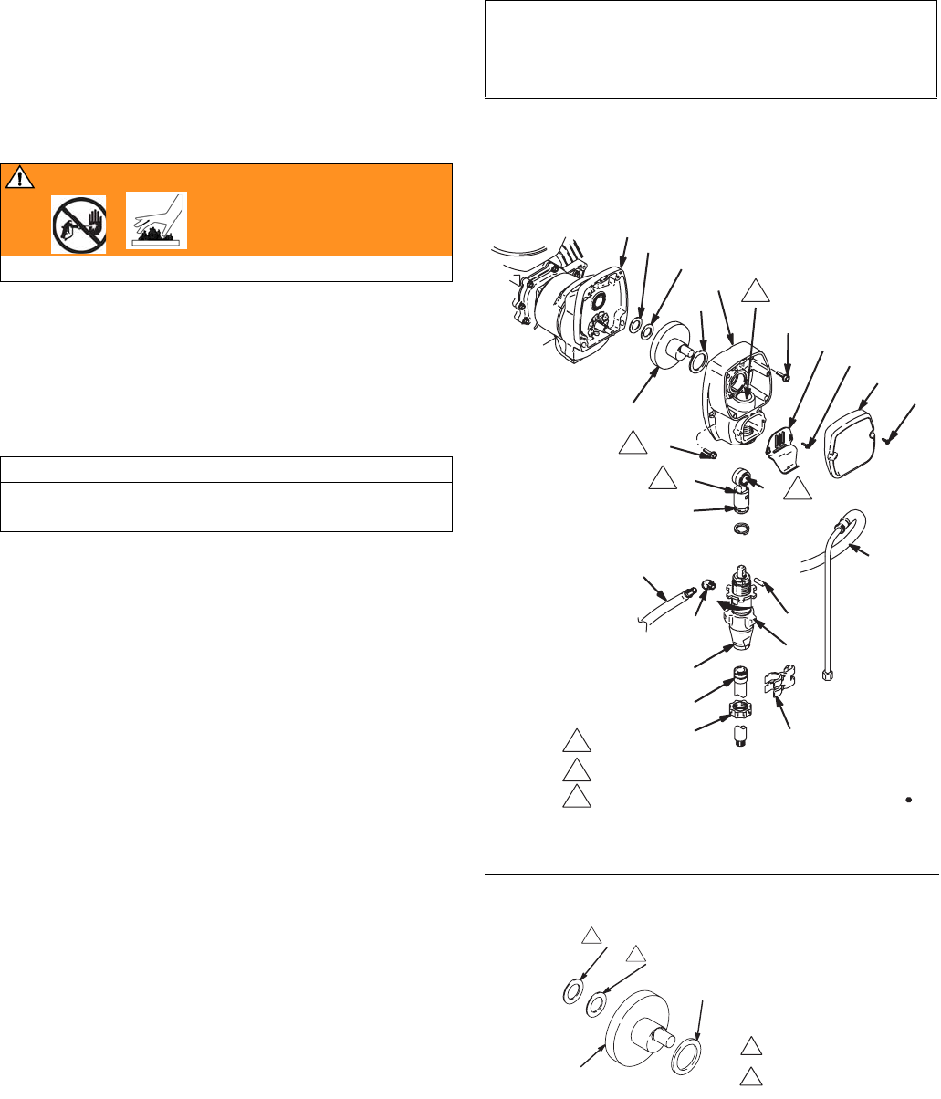
Pinion Assembly/Clutch Armature/Clamp
310813 Rev C 9
Pinion Assembly/Clutch Armature/Clamp
Pinion Assembly/Clutch Armature Removal
Pinion Assembly
If pinion assembly (50) is not removed from clutch housing
(51), do 1. through 3. Otherwise, start at 4.
1. Relieve pressure, page 5.
2. Remove drive housing; page 8.
3. FIG. 14. Disconnect clutch (A) and clutch (B) connectors
from control board.
a. Remove two screws (91) and swing down cover (77).
b. Remove strain relief 24b.
4.
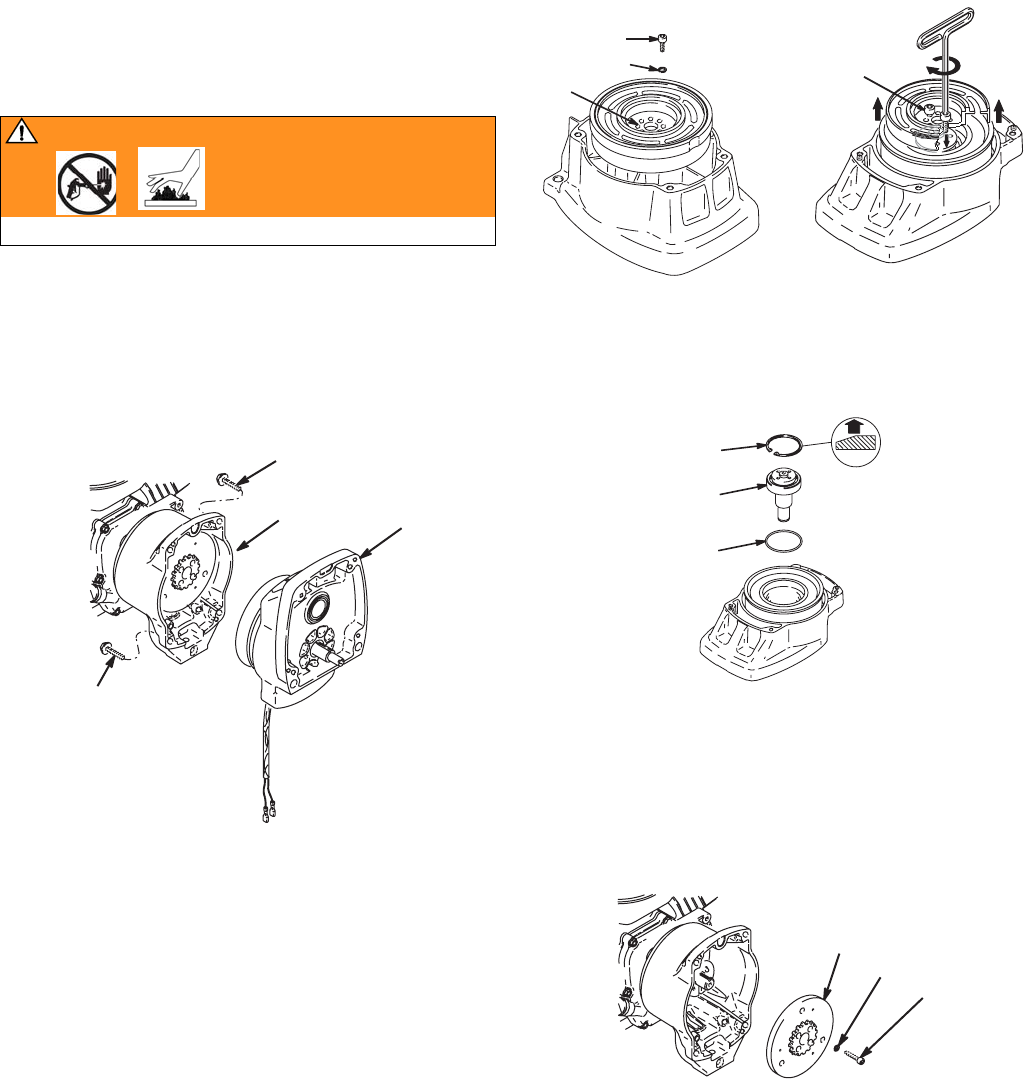
FIG. 3
. Remove four screws (18) and pinion assembly (50).
FIG. 3
5. FIG. 4. Place pinion assembly (50) on bench with rotor
side up.
6. Remove four screws (41) and lock washers (34). Install
two screws in threaded holes (E) in rotor. Alternately
tighten screws until rotor comes off.
FIG. 4
7. FIG. 5. Remove retaining ring (50d).
8. Turn pinion assembly over and tap pinion shaft (50c) out
with plastic mallet.
FIG. 5
Clutch Armature
9. FIG. 6. Use an impact wrench or wedge something
between clutch armature (38) and clutch housing to hold
engine shaft during removal.
10. Remove four screws (35) and lock washers (34).
11. Remove armature (38).
FIG. 6
WARNING
Read Injection Hazard, page 3; Burn Hazard, page 4
WLD
(
WLE
WLE
(
G
F
WLD
H
WLD

Pinion Assembly/Clutch Armature/Clamp
10 310813 Rev C
Installation
Clutch Armature
1. FIG. 7. Lay two stacks of two dimes on smooth bench
surface.
2. Lay armature (38) on two stacks of dimes.
3. Press center of hub down to bench surface.
FIG. 7
4. Install armature (38) on engine drive shaft.
5. Install four screws (35) and lock washers (34) with torque
of 125 in-lb.
Pinion Assembly
6. Install o-ring (50e).
7. FIG. 5. Tap pinion shaft (50c) in with plastic mallet.
8. Install retaining ring (50d) with beveled side facing up.
9. FIG. 4. Place pinion assembly on bench with rotor side up.
10. Apply locktite to screws. Install four screws (41) and lock
washers (34). Alternately torque screws to 125 in-lb until
rotor is secure. Use threaded holes to hold rotor.
11. FIG. 3. Install pinion assembly (50) with four screws (18).
12. FIG. 4. Connect clutch (A) and clutch (B) connectors to
control board.
Clamp Removal
1. Do Engine Removal.
2. Drain gasoline from tank according to Honda manual.
3.
FIG. 8
. Tip engine on side so gas tank is down and air
cleaner is up.
4. FIG. 9. Loosen two screws (35) on clamp (37),
5. Push screwdriver into slot in clamp (37) and remove
clamp.
FIG. 8
Clamp Installation
1. FIG. 9 Install engine shaft key (36)
2. Tap clamp (37) onto engine shaft (A). Maintain dimension
shown note 2. Chamfer must face engine.
3. Check dimension: Place rigid, straight steel bar (B) across
face of clutch housing (51). Use accurate measuring
device to measure distance between bar and face of
clamp. Adjust clamp as necessary. Torque two screws
(35) to 125 ±10 in-lb (14 ±1.1 N·m)
Face of clutch housing
1.550 ±.010 in. (39.37±.25 mm)
Torque to 125 ±.10 in-lb (14 ±1.1 N·m)
Chamfer this side
FIG. 9
LQPP
GLPHV
WLD
WARNING
Gasoline can spill and cause a fire or explosion if
engine is tipped on side.
WLD
%
$
WLD

Clutch Housing
310813 Rev C 11
Clutch Housing
Removal
1. Remove clamp. Do Clamp Removal, page 10.
2. FIG. 10. Remove four screws (60) and lock washers (59)
which hold clutch housing (51) to engine.
3. Remove screw (64) from under mounting plate (D).
4. Pull off clutch housing (51).
Installation
1. FIG. 10. Push on clutch housing (51).
2. Install four capscrews (60) and lock washers (59) and
secure clutch housing (51) to engine. Torque to 200 in-lb
(22.6 N·m).
3. Install screw (64) from beneath mounting plate (D).
Torque to 26 ft-lb (35.2 N·m).
FIG. 10
Engine
Removal
NOTE: All service to the engine must be performed by
an authorized HONDA dealer.
1. Remove Pinion Assembly/Clutch Armature/Clamp and
Clutch Housing, as instructed on pages 9, 10 and 11.
2. FIG. 11. Disconnect all necessary wiring.
3. FIG. 12. Remove two locknuts (3) and screws (2) from
base of engine.
4. Lift engine carefully and place on work bench.
FIG. 11
FIG. 12
Installation
1. Lift engine carefully and place on cart.
2. FIG. 12. Install two screws (2) in base of engine and
secure with locknuts (3). Torque to 20 ft-lb (27.12 N·m).
3. FIG. 11. Connect all necessary wiring.
4. Install Pinion Assembly/Clutch Armature/Clamp and
Clutch Housing, as instructed on pages 9 and 10 and 11.
5. Set engine to 3300 rpm.
'
WLD
7RWKHILHOG
7RWKHHQJLQH
*URXQG
*UHHQ
WLD
WLD
Pressure Control
12 310813 Rev C
Pressure Control
On/Off Switch
Removal
1. Relieve pressure, page 5.
2. FIG. 13. Remove two screws (91) and swing down
cover (77).
3. Disconnect ON/OFF switch connector (B) from PC board.
4. Press in on two retaining tabs on each side of ON/OFF
switch (71) and remove switch from cover.
Installation
1. Install new ON/OFF switch (71) so tabs of switch snap
into place on inside of cover.
2. Connect ON/OFF switch connector (B) to PC board.
3. Swing up cover (77) and secure with two screws (91).
FIG. 13
WARNING
Read Injection Hazard, page 3; Burn Hazard, page 4
&/87&+%
&/87&+$
(
D
E
%
7R(QJLQH
WLD
'
D
Pressure Control
310813 Rev C 13
Control Board
Removal
1. Relieve pressure, page 5.
2. FIG. 13. Remove two screws (91) and swing down
cover (77)
3. Remove strain relief bushing (24a).
4. Disconnect engine and ground wires.
5. Disconnect at control board (90):
• Lead (D) from potentiometer
• Lead (E) from transducer
• Lead (B) from ON/OFF switch
• Clutch wires
6. Remove four screws (89) and control board (90).
Installation
1. FIG. 13. Install control board (90) with four screws (89).
2. Connect at control board (90):
• Clutch wires
• Lead (B) from ON/OFF switch
• Lead (E) from transducer
• Lead (D) from potentiometer
3. Connect engine and ground wires.
4. Install strain relief bushing (24a).
5. Swing up cover (77) and secure with two screws (91).
Pressure Control Transducer
Removal
1. Relieve pressure, page 5.
2. FIG. 13. Remove two screws (91) and swing down
cover (77)
3. Disconnect lead (E) from control board (90).
4. Pull transducer connector through rubber grommet (78).
5. Remove pressure control transducer (20) and o-ring (63)
from filter housing (30).
Installation
1. FIG. 13. Install o-ring (63) and pressure control transducer
(20) in filter housing (30). Torque to 35 - 45 ft-lb.
2. Install transducer connector and rubber grommet in
control housing.
3. Connect lead (E) to control board (90).
4. Swing up cover (77) and secure with two screws (91).
Pressure Adjust Potentiometer
Removal
1. Relieve pressure, page 5.
2. Fig. 13.Remove two screws (91) and swing down
cover (77).
3. Disconnect lead (D) from control board (90).
4. Loosen set screws on potentiometer knob (68) and remove
knob, shaft nut, lock washer and potentiometer (70).
5. Remove seal (69) from potentiometer.
Installation
1. Install seal (69) on potentiometer (70).
2. FIG. 13. Install potentiometer, shaft nut, lock washer and
potentiometer knob (68).
a.Turn potentiometer shaft clockwise to internal stop.
Assemble potentiometer knob (68) to strike pin on
cover (77).
b.After adjustment of step a., tighten both set screws in
knob 1/4 to 3/8 turn after contact with shaft.
3. Connect lead (D) to control board (90).
4. Swing up cover (77) and secure with two screws (91).
WARNING
Read Injection Hazard, page 3; Burn Hazard, page 4
WARNING
Read Injection Hazard, page 3; Burn Hazard, page 4
WARNING
Read Injection Hazard, page 3; Burn Hazard, page 4

Displacement Pump
14 310813 Rev C
Displacement Pump
Removal
1. Flush pump.
2. Relieve pressure, page 5.
3. FIG. 15. Stop pump with piston rod (201) in its lowest
position.
4.
FIG. 14
. Loosen two screws (10) and remove pail hook (9).
FIG. 14
5. FIG. 15. Remove hose (93). Use screwdriver; push
retaining spring up; push out pin (8).
FIG. 15
6. FIG. 16. Loosen jam nut by hitting firmly with a 20 oz
hammer. Unscrew pump.
FIG. 16
Repair
See manual 309250 for pump repair instructions
WARNING
Read Injection Hazard, page 3; Burn Hazard, page 4
WLD
9
10
WLD
WLD

Displacement Pump
310813 Rev C 15
Installation
1. Fig. FIG. 17. Pull piston rod out. Screw in pump until holes
in connecting rod and piston rod align.
FIG. 17
2. FIG. 11. Push pin (8) into hole. Push retaining ring spring
into groove all the way around connecting rod.
3.
FIG. 18
. Screw jam nut down onto pump until nut stops.
Screw pump up into drive housing until top threads of pump
are flush with drive housing face (
FIG. 19
). Back off pump
and jam nut to align pump outlet to side. Tighten jam nut by
hand, then tap 1/8 to 1/4 turn with a 20 oz (maximum)
hammer to approximately 75 ±5 ft-lb (102 N·m). Connect
hose (93).
FIG. 18
4. FIG. 19. Fill packing nut with Graco TSL until fluid flows
onto the top of seal. Install pail hook (9).
FIG. 19
WARNING
If pin works loose, parts could break off and project
through the air and result in serious injury or property
damage. Make sure pin is properly installed.
CAUTION
• Replacement pump comes with an outlet fitting
installed. Replace installed fitting with fitting marked
“GMAX 3400”.
• If the pump jam nut loosens during operation, the
threads of the bearing housing and drive train will
be damaged. Tighten jam nut as specified.
WLD
WLD
WLD
WLD
WLD
Drive housing face
Parts
16 310813 Rev C
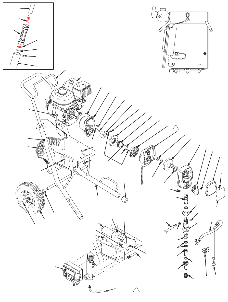
Parts
Parts Drawing - GMAX 3400 Hi-Boy Sprayers
'(7$,/$
5HI
5HI
'(7$,/$
%RWWRP9LHZ
5HI
WLD
)253$576
6((3$*(
6HHSDUWVSDJH
Parts
310813 Rev C 17
Parts List - GMAX 3400 Hi-Boy Sprayers
Model 248663
▲Replacement Danger and Warning labels, tags, and
cards are available at no cost
* Included in Clutch Replacement Kit 241109
Ref.
No. Part No. Description Qty.
1 108879 ENGINE, gasoline, 4.0 HP 1
2 110837 SCREW, flange, hex 2
3 110838 NUT, lock 2
4 246428 PUMP, displacement, st 1
Manual 309250
5 119789 FITTING, elbow, street, 45°, 1/4 npt 2
6 287053 ROD, connecting 1
7 195150 NUT, jam, pump 1
8 196762 PIN, straight 1
9 15C146 HOOK, pail 1
10 117501 SCREW, mach, hex washer hd 4
11 115099 WASHER, garden hose 1
12 15E813 NUT, jam 1
13 15B652 WASHER, suction 1
14 103413 O-RING 2
15 15E805 TUBE, intake (3400) 1
16 246385 STRAINER, 7/8-14 unf 1
17 276888 CLIP, drain line 1
18 119426 SCREW, mach, hex washer hd 8
19 287411 FRAME, cart (GMAX 3400 hi) 1
34 105510* WASHER, lock, spring (hi-collar) 10
35 108803 SCREW, hex, socket head 6
36 183401 KEY, parallel 1
37 193680 COLLAR, shaft 1
38 * ARMATURE, clutch, 4 in. 1
39 * HUB, armature 1
40 * ROTOR, clutch, 4 in. 1
41 101682* SCREW, cap, sch 4
42 112827 BUTTON, snap 2
43 192027 SLEEVE, cart 2
44 108068 PIN, spring straight 2
45 183350 WASHER, 2
46 245245 HANDLE, cart 1
48 109032 SCREW, mach, pnh 4
49 287483 HOUSING, drive, 3400 1
includes 9, 10, 18 & grease 110293
50 287376 HOUSING, pinion, 3400 1
51 15E535 HOUSING, clutch, mach, 3400 1
52 116074 WASHER, thrust 1
53 287484 CRANK, GMAX 3400 1
includes 52, 56, 57
54 244240 HOSE, coupled, includes 55 1
55 241920 DEFLECTOR, threaded 1
56 180131 BEARING, thrust 1
57 107434 BEARING, thrust 1
59 100214 WASHER, lock 4
60 108842 SCREW, cap, hex hd 4
61 119420 WHEEL, pneumatic 2
62 287487 COVER, front, painted, includes 10 1
64 112395 SCREW, cap, flnghd 1
67 15C871 CAP, leg 2
72 237686 WIRE, ground assembly w/clamp 1
73 112798 SCREW, thread forming, hex hd 1
80 156306 WASHER, flat 2
82 119510 HOLDER, manual 1
83 15E736 BRACKET, holder, manual 1
93 241926 HOSE, coupled 1
94 15E850 LABEL, identification 1
95 15E891 CLIP, retaining 2
99▲15F638 LABEL, warning 1
100 114678 BUSHING, strain relief 1
101 119569 BUSHING, strain relief 1
Ref.
No. Part No. Description Qty.
Parts
18 310813 Rev C
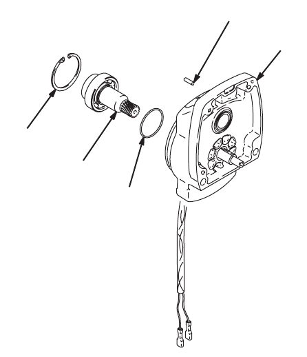
Parts Drawing and List - Pinion Housing
Ref No. 50: Pinion Housing
* Must be ordered separately
No. Part No. Description Qty
50 PINION HOUSING 1
50a 287482 KIT, repair, coil 1
50b 105489 PIN 2
50c* 287485 PINION SHAFT 1
50d* 113094 RETAINING RING, large 1
D
F
G
WLD
E
H

Parts
310813 Rev C 19
Notes

Parts
20 310813 Rev C
Parts Drawing - GMAX 3400 Lo-Boy Sprayers
'(7$,/$
5HI
5HI
'(7$,/$
%RWWRP9LHZ
WLD
)253$576
6((3$*(
6HHSDUWVSDJH
5HI
6a
Parts
310813 Rev C 21
Parts List - GMAX 3400 Lo-Boy Sprayers
Model 248665
▲Replacement Danger and Warning labels, tags, and
cards are available at no cost
* Included in Clutch Replacement Kit 241109
† Included in Suction Hose Kit 249356
Ref
No. Part No. Description Qty
1 108879 ENGINE, gasoline, 4.0 HP 1
2 110837 SCREW, flange, hex 2
3 110838 NUT, LOCK 2
4 246428 PUMP, displacement, st 1
Manual 309250
5 119789 FITTING, elbow, street, 45°, 1/4 npt 2
6 287053 ROD, connecting; includes 6a, 8 1
6a 196750 RING, retaining 1
7 195150 NUT, jam, pump 1
8 196762 PIN, straight 1
9 15C146 HOOK, pail 1
10 117501 SCREW, mach, hex washer hd 4
11† 115099 WASHER, garden hose 1
12 15E813 NUT, jam 1
14† 103413 PACKING, o-ring 2
15† 287416 HOSE, suction 1
16† 246385 STRAINER, 7/8-14 unf 1
17† 276888 CLIP, drain line 1
18 119426 SCREW, mach, hex washer hd 8
19 287411 FRAME, cart (GMAX 3400 Hi) 1
34 105510* WASHER, lock, spring (hi-collar) 10
35 108803 SCREW, hex, socket head 6
36 183401 KEY, parallel 1
37 193680 COLLAR, shaft 1
38 * ARMATURE, clutch, 4 in. 1
39 * HUB, armature 1
40 * ROTOR, clutch, 4 in. 1
41 101682* SCREW, cap, sch 4
42 112827 BUTTON, snap 2
43 192027 SLEEVE, cart 2
44 108068 PIN, spring straight 2
45 183350 WASHER 2
46 245245 HANDLE, cart 1
48 109032 SCREW, mach, pnh 4
49 287483 HOUSING, drive, 3400 1
includes 9, 10, 18 & grease 110293
50 287376 HOUSING, pinion, 3400 1
51 15E535 HOUSING, clutch, mach, 3400 1
52 116074 WASHER, thrust 1
53 287484 CRANK, GMAX 3400 1
includes 52, 56, 57
54† 244240 HOSE, coupled, includes 55 1
55† 241920 DEFLECTOR, threaded 1
56 180131 BEARING, thrust 1
57 107434 BEARING, thrust 1
59 100214 WASHER, lock 4
60 108842 SCREW, cap, hex hd 4
61 119420 WHEEL, pneumatic 2
62 287487 COVER, front, painted, includes 10 1
64 112395 SCREW, cap, flng hd 1
67 15C871 CAP, leg 2
72 237686 WIRE, gnd assy w/clamp 1
73 112798 SCREW, thread forming, hex hd 1
80 156306 WASHER, flat 2
82 119510 HOLDER, manual 1
83 15E736 BRACKET, holder, manual 1
93 241926 HOSE, coupled 1
94 15E850 LABEL, identification 1
95 15E891 CLIP, retaining 2
99▲15F638 LABEL, warning 1
100 114678 BUSHING, strain relief 1
101 119569 BUSHING, strain relief 1
Ref
No. Part No. Description Qty

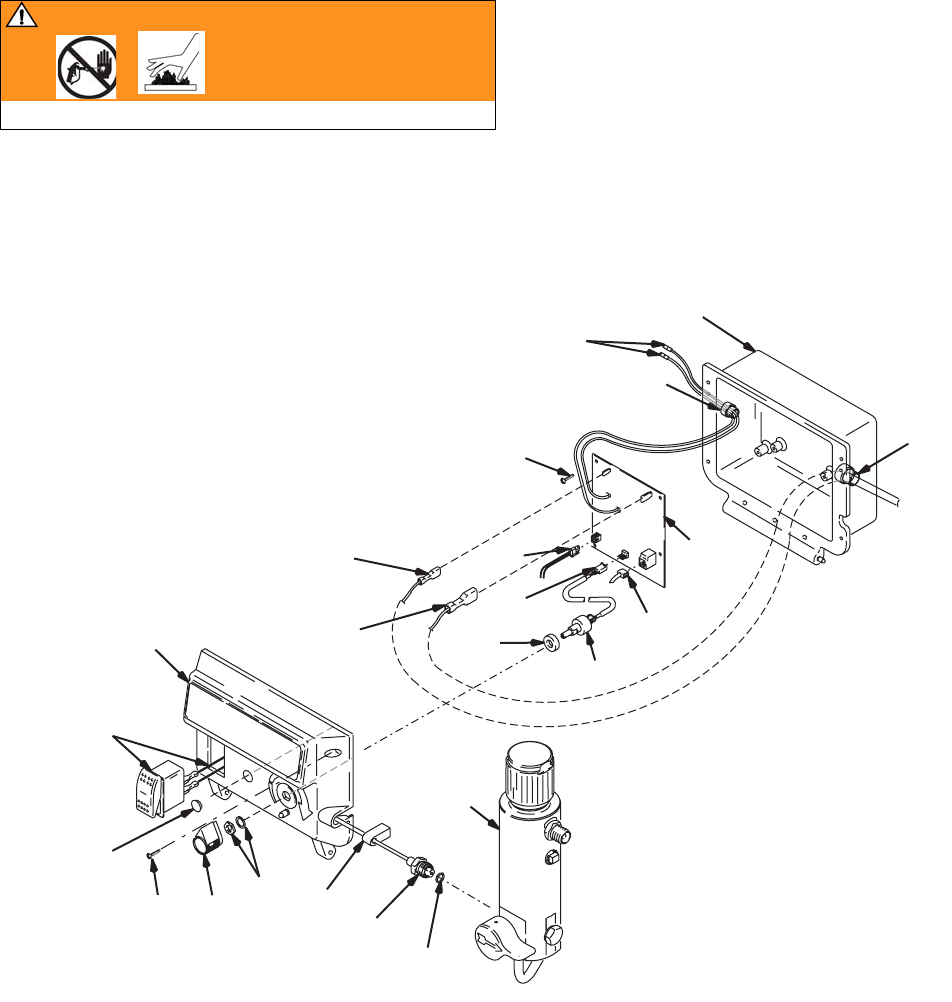
Pressure Control/Filter Assembly
22 310813 Rev C
Pressure Control/Filter Assembly
GMAX 3400 Sprayers
Models 248663 through 248666
&/87&+%
&/87&+$
E
$
$WR(QJLQH
E
D
D
WLD
Pressure Control/Filter Assembly
310813 Rev C 23
Pressure Control/Filter Assembly
GMAX 3400 Sprayers
Models 248663 through 248666
REF
NO.
PART
NO. DESCRIPTION
QT
Y
20 243222 TRANSDUCER, pressure contl
includes 63
1
21 224807 BASE, valve 1
22 235014 VALVE, drain; includes 22a, 22b 1
24 119545 BUSHING, strain, relief 2
25 15C780 HANDLE, 1
26 15C972 PIN, grooved 1
27 164672 NIPPLE, adapter 1
28 15C766 TUBE, diffusion 1
29 FILTER, fluid
244071 30 mesh 1
244067 60 mesh, original equipment 1
244068 100 mesh 1
244069 200 mesh 1
30 15E284 HOUSING, filter 1
31 287285 CAP, filter, includes 28, 58 1
58 117285 O-RING 1
63 111457 O-RING 1
65 248314 PLUG, auto clean, includes 66 1
66 15D541 SEAL, washer 1
68 116167 KNOB, potentiometer 1
69 198650 SPACER, shaft 1
70 241443
POTENTIOMETER; includes 70a, 70b
1
71 116752 SWITCH, rocker 1
77 249357
BOX, control
includes 68, 69, 70, 71, 79, 89, 90, 97
1
78 15E925 GASKET, transducer 1
79 119548 PLUG, cap 1
81 113161 SCREW, flange, hex hd 3
84 164672 ADAPTER 1
85 104813 PLUG, pipe 1
89 117317 SCREW, plastite, pan head 4
90 287486 CONTROL, board, 3400 1
91 116585 SCREW, mach, pan hd 6
97 15E856 LABEL, identification 1
REF
NO.
PART
NO. DESCRIPTION
QT
Y
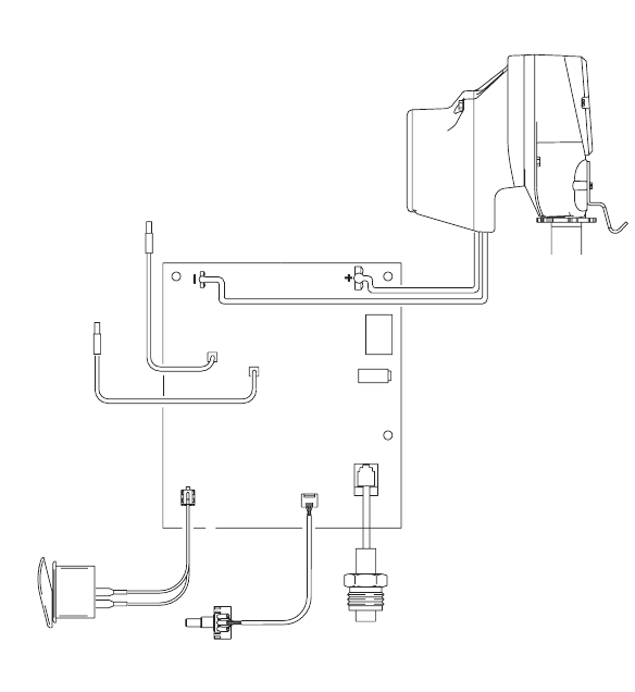
3UHVVXUH&RQWURO
:LULQJ'LDJUDP
WLD
72(1*,1(
72*5281'
212))6:,7&+
327(17,20(7(5
75$16'8&(5
&21752/%2$5'
3,121
+286,1*
'5,9(
+286,1*
&/87&+% &/87&+$

Complete Sprayers - with RAC X Tip, Gun & Hose
24 310813 Rev C
Complete Sprayers - with RAC X Tip, Gun & Hose
Models 248664, 248666
GMAX 3400 Airless Paint Sprayers
Includes items 201 to 204
Ref
No. Part No. Description Qty
201 248663 Hi-Boy Sprayer 1
See parts list on page 17
248665 Lo-Boy Sprayer 1
See parts list on page 21
202 240794 HOSE, grounded, nylon; 1/4 in. ID; 1
cpld 1/4 npsm(fbe); 50 ft (15 m);
spring guards both ends
3300 psi (227 bar, 27.7 MPa)
203 238358 HOSE, grounded, nylon; 3/16 in.
ID;
cpld 1/4 npsm(m) x 1/4 npsm(f)
swivel;
3 ft (0.9 m); spring guards both
ends
1
204 246220 CONTRACTOR II SPRAY GUN
Includes RAC X 517-size SwitchTip
and HandTite Guard
See 309639 for parts 1
WLD

Technical Data
310813 Rev C 25
Technical Data
Dimensions
Honda GX120 Engine
ANSI Power Rating @ 3600 rpm 4.0 Horsepower
(2.9 kW)
Maximum working pressure 3300 psi
(227 bar, 22.7 MPa)
Noise Level
Sound power 100 dBa
per ISO 3744
Sound pressure 86 dBa
measured at 3.1 feet (1 m)
Maximum delivery rating 0.75 gpm (2.84 liter/min)
Maximum tip size 1 gun with 0. 027 in. tip
Inlet paint strainer 12 mesh (893 micron)
stainless steel screen, reusable
Outlet paint filter 60 mesh (250 micron)
stainless steel screen, reusable
Pump inlet size 1¼-12 unf-2b
Fluid outlet size ¼ npsm from fluid filter
Wetted parts zinc-plated carbon steel,
PTFE, Nylon, polyurethane, UHMW polyethylene, fluo-
roelastomer, acetal, leather, aluminum, tungsten carbide,
nickel- and zinc-plated carbon steel, stainless steel,
chrome plating
Sprayer
(without hose and gun)
Weight lb (kg) Height in. (cm) Width in. (cm) Length in. (cm)
248663 Hi-Boy 89 (40.4) 31.5 (80) 22.5 (58) 31 (79)
248665 Lo-Boy 89 (40.4) 31.5 (80) 22.5 (58) 31 (79)

Graco Standard Warranty
26 310813 Rev C
Graco Standard Warranty
Graco warrants all equipment referenced in this document which is manufactured by Graco and bearing its name to be free from defects in
material and workmanship on the date of sale to the original purchaser for use. With the exception of any special, extended, or limited warranty
published by Graco, Graco will, for a period of twelve months from the date of sale, repair or replace any part of the equipment determined by
Graco to be defective. This warranty applies only when the equipment is installed, operated and maintained in accordance with Graco’s written
recommendations.
This warranty does not cover, and Graco shall not be liable for general wear and tear, or any malfunction, damage or wear caused by faulty
installation, misapplication, abrasion, corrosion, inadequate or improper maintenance, negligence, accident, tampering, or substitution of
non-Graco component parts. Nor shall Graco be liable for malfunction, damage or wear caused by the incompatibility of Graco equipment with
structures, accessories, equipment or materials not supplied by Graco, or the improper design, manufacture, installation, operation or
maintenance of structures, accessories, equipment or materials not supplied by Graco.
This warranty is conditioned upon the prepaid return of the equipment claimed to be defective to an authorized Graco distributor for verification of
the claimed defect. If the claimed defect is verified, Graco will repair or replace free of charge any defective parts. The equipment will be returned
to the original purchaser transportation prepaid. If inspection of the equipment does not disclose any defect in material or workmanship, repairs will
be made at a reasonable charge, which charges may include the costs of parts, labor, and transportation.
Graco’s sole obligation and buyer’s sole remedy for any breach of warranty shall be as set forth above. The buyer agrees that no other remedy
(including, but not limited to, incidental or consequential damages for lost profits, lost sales, injury to person or property, or any other incidental or
consequential loss) shall be available. Any action for breach of warranty must be brought within two (2) years of the date of sale.
GRACO MAKES NO WARRANTY, AND DISCLAIMS ALL IMPLIED WARRANTIES OF MERCHANTABILITY AND FITNESS FOR A
PARTICULAR PURPOSE, IN CONNECTION WITH ACCESSORIES, EQUIPMENT, MATERIALS OR COMPONENTS SOLD BUT NOT
MANUFACTURED BY GRACO. These items sold, but not manufactured by Graco (such as electric motors, switches, hose, etc.), are subject to
the warranty, if any, of their manufacturer. Graco will provide purchaser with reasonable assistance in making any claim for breach of these
warranties.
In no event will Graco be liable for indirect, incidental, special or consequential damages resulting from Graco supplying equipment hereunder, or
the furnishing, performance, or use of any products or other goods sold hereto, whether due to a breach of contract, breach of warranty, the
negligence of Graco, or otherwise.
FOR GRACO CANADA CUSTOMERS
The Parties acknowledge that they have required that the present document, as well as all documents, notices and legal proceedings entered into,
given or instituted pursuant hereto or relating directly or indirectly hereto, be drawn up in English. Les parties reconnaissent avoir convenu que la
rédaction du présente document sera en Anglais, ainsi que tous documents, avis et procédures judiciaires exécutés, donnés ou intentés, à la suite
de ou en rapport, directement ou indirectement, avec les procédures concernées.
ADDITIONAL WARRANTY COVERAGE
Graco does provide extended warranty and wear warranty for products described in the Graco Contractor Equipment Warranty Program.
TO PLACE AN ORDER, contact your Graco distributor, or call 1-800-690-2894 to identify the nearest distributor.
All written and visual data contained in this document reflects the latest product information available at the time of publication.
Graco reserves the right to make changes at any time without notice.
English GN 310813 MM 310813
Graco Headquarters: Minneapolis
International Offices: Belgium, Korea, China, Japan
GRACO INC. P.O. BOX 1441 MINNEAPOLIS, MN 55440-1441
http://www.graco.com
Written in U.S.A. 2/2005, Rev 11/2006
