Graco 3A0260H Pgm Precision Gear Metering Users Manual PGM, Metering, Instructions Parts, English
2015-04-02
: Graco Graco-3A0260H-Pgm-Precision-Gear-Metering-Users-Manual-686129 graco-3a0260h-pgm-precision-gear-metering-users-manual-686129 graco pdf
Open the PDF directly: View PDF ![]() .
.
Page Count: 100
- Related Manuals
- Models
- Warnings
- Overview
- Installation
- System Setup
- Operation
- Pressure Relief Procedure
- Shutdown
- Troubleshooting
- Errors
- Maintenance
- Repair
- Parts
- PGM-20 Mounting Frame
- PGM-20 Lower Assembly Block
- PGM-20 Pump Heat Kit
- PGM Drive - 20 cc Pump
- Endure Dispense Valve Fix Mounted
- Gear Meter Assembly Panel
- PGM Back Panel
- Remote Mount Amplifiers
- PGM Remote Dispense Valve
- PGM Transducer
- PGM-6 Mounting Frame
- PGM-6 Drive Kit
- PGM-6 Lower Assembly Block
- PGM-6 Pump Heat Kit
- Schematics
- Accessory Parts
- Appendix A - User Interface Display
- Appendix B - I/O
- Appendix C - Theory of Operation
- Technical Data
- Graco Standard Warranty
- Graco Information
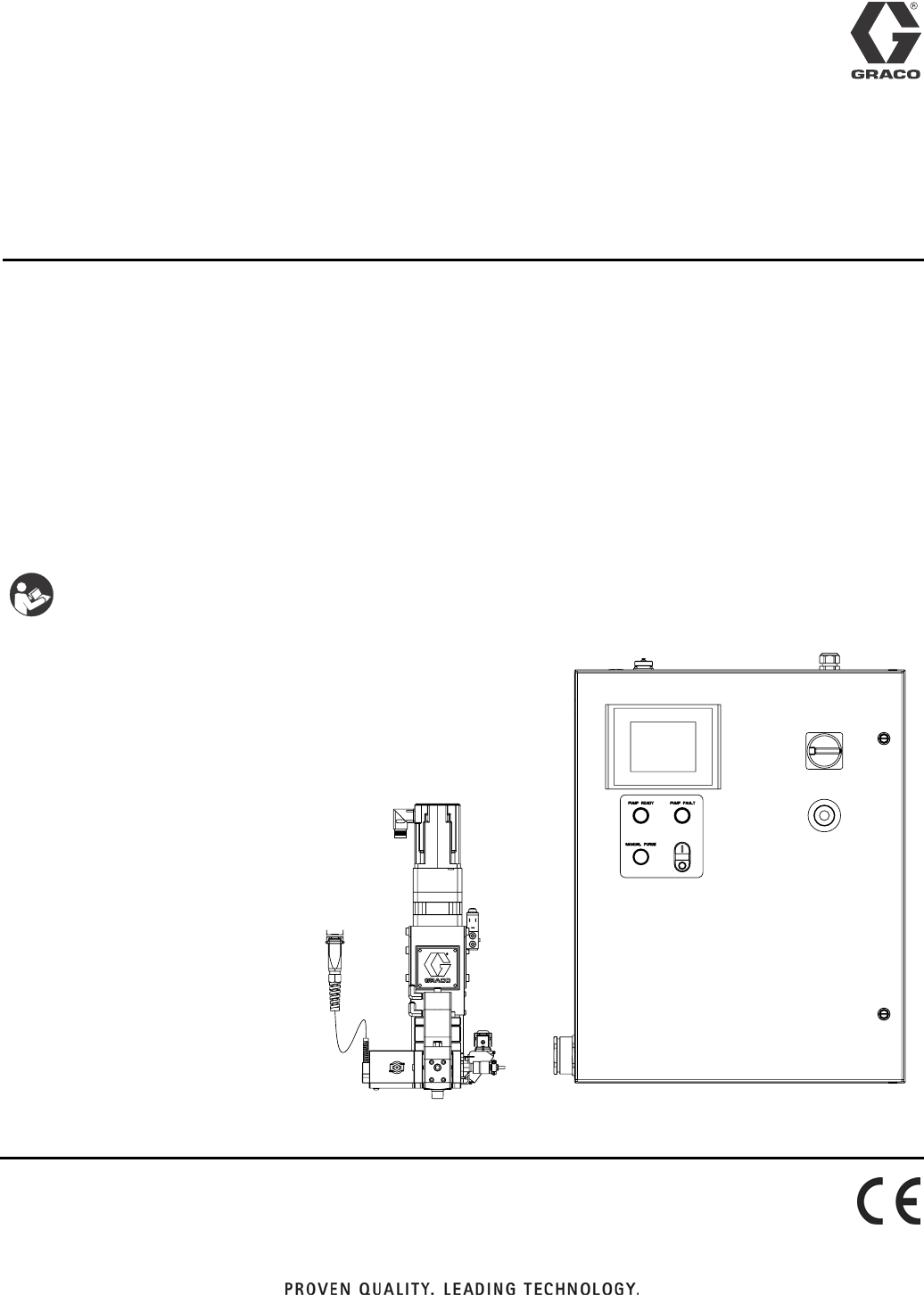
Instructions - Parts
PGM
Precision Gear Metering
For metering and dispensing ambient or high-temperature, high-viscosity
single-component materials.
Not approved for use in European explosive atmosphere locations.
For professional use only.
2500 psi (17.2 MPa, 172 bar) Maximum Working Outlet Pressure
1500 psi (10.3 MPa, 103 bar) Maximum Working Inlet Pressure
See Technical Data on page 99 for temperature ranges
See page 4 for model information.
Important Safety Instructions
Read all warnings and instructions in this
manual. Save these instructions.
3A0260H
EN
23A0260H
Contents
Related Manuals . . . . . . . . . . . . . . . . . . . . . . . . . . . 3
Models . . . . . . . . . . . . . . . . . . . . . . . . . . . . . . . . . . . 4
Bulk Melt (Therm-O-Flow 20 + Therm-O-Flow 200)
and Ambient Hoses . . . . . . . . . . . . . . . . . . . 4
Remote Dispense Valves . . . . . . . . . . . . . . . . . . 5
Fixed Dispense Valves . . . . . . . . . . . . . . . . . . . . 5
Accessories . . . . . . . . . . . . . . . . . . . . . . . . . . . . . 5
Warnings . . . . . . . . . . . . . . . . . . . . . . . . . . . . . . . . . 6
Overview . . . . . . . . . . . . . . . . . . . . . . . . . . . . . . . . . . 9
System Configurations . . . . . . . . . . . . . . . . . . . . 9
Component Identification . . . . . . . . . . . . . . . . . 11
System Overview . . . . . . . . . . . . . . . . . . . . . . . 12
Typical Applications . . . . . . . . . . . . . . . . . . . . . . 12
Installation . . . . . . . . . . . . . . . . . . . . . . . . . . . . . . . 13
Before Installation . . . . . . . . . . . . . . . . . . . . . . . 13
Overview . . . . . . . . . . . . . . . . . . . . . . . . . . . . . . 13
Install Control Center . . . . . . . . . . . . . . . . . . . . 14
Install Gear Meter Assembly . . . . . . . . . . . . . . . 15
Install Cable Assemblies . . . . . . . . . . . . . . . . . . 18
System Setup . . . . . . . . . . . . . . . . . . . . . . . . . . . . . 19
Overview . . . . . . . . . . . . . . . . . . . . . . . . . . . . . . 19
Configure Control Settings . . . . . . . . . . . . . . . . 20
Configure Mode Settings . . . . . . . . . . . . . . . . . 20
Configure Delay Settings . . . . . . . . . . . . . . . . . 21
Adjust Pressure Sensors . . . . . . . . . . . . . . . . . 21
Configure Errors . . . . . . . . . . . . . . . . . . . . . . . . 22
Operation . . . . . . . . . . . . . . . . . . . . . . . . . . . . . . . . 23
Startup . . . . . . . . . . . . . . . . . . . . . . . . . . . . . . . 23
Load Material . . . . . . . . . . . . . . . . . . . . . . . . . . 23
Maintenance Mode Operation . . . . . . . . . . . . . . 24
Calibration . . . . . . . . . . . . . . . . . . . . . . . . . . . . . 25
Dispense from Maintenance Screen . . . . . . . . . 26
Automation Control (Normal) Operation . . . . . . 27
Typical Automation Cycle . . . . . . . . . . . . . . . . . 27
Pressure Relief Procedure . . . . . . . . . . . . . . . . . . 28
Shutdown . . . . . . . . . . . . . . . . . . . . . . . . . . . . . . . . 30
Troubleshooting . . . . . . . . . . . . . . . . . . . . . . . . . . . 31
PGM Fluid Assembly . . . . . . . . . . . . . . . . . . . . . 31
Dispense Valves . . . . . . . . . . . . . . . . . . . . . . . . 32
Errors . . . . . . . . . . . . . . . . . . . . . . . . . . . . . . . . . . . 33
View Errors . . . . . . . . . . . . . . . . . . . . . . . . . . . . 33
Diagnose Errors . . . . . . . . . . . . . . . . . . . . . . . . 33
Clear Errors and Reset Control Unit . . . . . . . . . 33
Error Codes and Troubleshooting . . . . . . . . . . . 33
Maintenance . . . . . . . . . . . . . . . . . . . . . . . . . . . . . . 36
Maintenance Schedule . . . . . . . . . . . . . . . . . . . 36
Repair . . . . . . . . . . . . . . . . . . . . . . . . . . . . . . . . . . . 37
Gear Meter Assembly . . . . . . . . . . . . . . . . . . . . 37
PGM-6 Pump Repair . . . . . . . . . . . . . . . . . . . . . 42
PGM-20 Pump Repair . . . . . . . . . . . . . . . . . . . . 46
Gear Pump Maintenance Guide . . . . . . . . . . . . 49
Installing new heater units and RTD sensors . . 50
Parts . . . . . . . . . . . . . . . . . . . . . . . . . . . . . . . . . . . . 51
PGM-20 Mounting Frame . . . . . . . . . . . . . . . . . 51
PGM-20 Lower Assembly Block . . . . . . . . . . . . 52
PGM-20 Pump Heat Kit . . . . . . . . . . . . . . . . . . 53
PGM Drive - 20 cc Pump . . . . . . . . . . . . . . . . . . 54
Endure Dispense Valve Fix Mounted . . . . . . . . 55
Gear Meter Assembly Panel . . . . . . . . . . . . . . . 56
PGM Back Panel . . . . . . . . . . . . . . . . . . . . . . . 58
Remote Mount Amplifiers . . . . . . . . . . . . . . . . . 59
PGM Remote Dispense Valve . . . . . . . . . . . . . 60
PGM Transducer . . . . . . . . . . . . . . . . . . . . . . . . 61
PGM-6 Mounting Frame . . . . . . . . . . . . . . . . . . 62
PGM-6 Drive Kit . . . . . . . . . . . . . . . . . . . . . . . . 63
PGM-6 Lower Assembly Block . . . . . . . . . . . . . 64
PGM-6 Pump Heat Kit . . . . . . . . . . . . . . . . . . . 65
Schematics . . . . . . . . . . . . . . . . . . . . . . . . . . . . . . . 66
Accessory Parts . . . . . . . . . . . . . . . . . . . . . . . . . . . 76
Automation Interface Cable Assembly . . . . . . . . 76
Dynamic Regulators . . . . . . . . . . . . . . . . . . . . . 77
Endure Valve Nozzles . . . . . . . . . . . . . . . . . . . . 80
Heater Nests . . . . . . . . . . . . . . . . . . . . . . . . . . . 80

Related Manuals
3A0260H 3
Appendix A - User Interface Display . . . . . . . . . . 81
Screen Navigation Diagram . . . . . . . . . . . . . . . . 81
Main Screen . . . . . . . . . . . . . . . . . . . . . . . . . . . 82
Calibrate Screen #1 . . . . . . . . . . . . . . . . . . . . . . 83
Calibrate Screen #2 . . . . . . . . . . . . . . . . . . . . . . 84
Home Screen . . . . . . . . . . . . . . . . . . . . . . . . . . 85
Maintenance Screen . . . . . . . . . . . . . . . . . . . . . 86
Robot I/O Screen . . . . . . . . . . . . . . . . . . . . . . . . 87
Setup #1 Screen . . . . . . . . . . . . . . . . . . . . . . . . 88
Setup #2 Screen . . . . . . . . . . . . . . . . . . . . . . . . 89
Setup #3 Screen . . . . . . . . . . . . . . . . . . . . . . . . 90
Setup #4 Screen . . . . . . . . . . . . . . . . . . . . . . . . 91
Setup #5 Screen . . . . . . . . . . . . . . . . . . . . . . . . 92
Setup #6 Screen . . . . . . . . . . . . . . . . . . . . . . . . 93
Supply Pump Screen . . . . . . . . . . . . . . . . . . . . . 94
Appendix B - I/O . . . . . . . . . . . . . . . . . . . . . . . . . . . 95
Using the PGM I/O . . . . . . . . . . . . . . . . . . . . . . 95
Appendix C - Theory of Operation . . . . . . . . . . . . 98
Theory of Operation . . . . . . . . . . . . . . . . . . . . . 98
Technical Data . . . . . . . . . . . . . . . . . . . . . . . . . . . . 99
Graco Standard Warranty . . . . . . . . . . . . . . . . . . 100
Graco Information . . . . . . . . . . . . . . . . . . . . . . . . 100
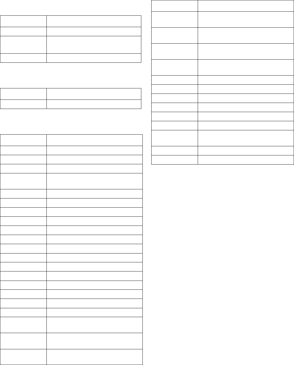
Related Manuals
Part Description
309376 Endure Dispense Valve
310538 Heated Automatic Dispense Valve
311208 Therm-O-Flow 200
313296 Warm Melt Supply System
309213 Accessory Heat Zone Controls
313526 Ambient Supply Systems
Models
43A0260H
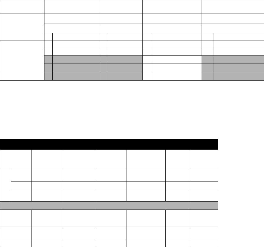
Models
Check the identification (ID) plate for the 6-digit part number of the fluid metering system. Use the following matrix to
define the construction of the system, based on the six digits. For example, Part PG0111 represents a PGM fluid
metering system (PG), with a 6cc system (0), unheated (1), with controls/3m (1), and an Endure snuff-back (1).
NOTE: To order replacement parts, see Parts section in this manual. The digits in the matrix do not corre-
spond to the Ref. Nos. in the Parts drawings and lists.
* PGM Control Center does not include heat controls. Heat loads are configured to be controlled by Therm-O-Flow
Controllers.
Bulk Melt (Therm-O-Flow 20 + Therm-O-Flow 200) and Ambient
Hoses
* Indicates PTFE hose, all others Buna-N.
† Indicates swivel.
PG 0 112
First and
Second Digits
Third Digit Fourth Digit Fifth Digit Sixth Digit
Size Heat Controls * Valve
Description Description Description Description
PG
(Precision
Gear Meter)
06cc 1Unheated 0No controls 1Endure snuff-back
220cc 2Heated 1Controls / 3m 6Remote mount
2Controls / 6m
3Controls / 9m
4Controls / 15m
Hose Diameter
- 8
3/4 in. - 16 JIC - 10
7/8 in. - 14 JIC
- 12
1-1/16 in. - 12
JIC - 16
1-5/16 in. - 12 JIC 3/8 in. 1/2 in.
Hose Length
6 ft None 115875 None 115884 109163 626720
(1/2 in. x 5 ft)
10 ft 115873 115876 115880 115885 None 215441
15 ft Non None None None 109165/
685602* 511381*
Fittings
PGM Inlet
(-16 SAE) None None 124238
124235 (90°) 124239
124243 †
124236 (90°)
None None
PGM Outlet
(3/4 in. npt) 124286 C20595 15M863 107127 124290 † 124289 †
Valve Inlet 124287 C20768 107052 124288 158256 † 190451 †
Models
3A0260H 5
Remote Dispense Valves
Fixed Dispense Valves
Accessories
Part Description
243694 Heated Dispense Valve
244951 Endure Valve™, Heated,
1/2 in. npt male outlet
244909 Endure Valve, Heated
Part Description
244907 Endure Valve snuff-back
Part Description
24D824 Automation I/O Cable
24E654 Ribbon Nozzle Kit, 10 x 1.5 mm
24E655 Bead Nozzle Kit, 3 mm dia.
24E575 Dynamic Air Regulator for
Therm-O-Flow
24E607 Gear Pump Seals, 6 cc
24E619 Gear Pump Seals, 20 cc
24E677 O-ring Kit, 6 cc
24E626 O-ring Kit, 20 cc
24E678 Heated Nest, Pilot
24E679 Heated Nest, Ribbon or Bead
16E242 Nozzle Heater Insert
16E256 Ported Nozzle Heater Insert
124267 Seal Housing, 6 cc
24E826 Gear Shaft Repair Kit, 6 cc
24E827 Seal Shaft Repair Kit, 6 cc
124266 Pump Seal Housing, 20 cc
24E824 Gear Shaft Repair Kit, 20 cc
24E825 Seal Shaft Repair Kit, 20 cc
124235 Elbow Fitting, 90 degree, 3/4 in.
tube x 16 SAE
124236 Elbow Fitting, 90 degree, 1 in. tube
x 16 SAE
124237 Elbow Fitting, 90 degree, 16 SAE x
20 JIC
124238 Adapter Fitting, 3/4 in. Tube x
16 SAE
124239 Adapter Fitting, 1 in. Tube x
16 SAE
124240 Adapter Fitting, 1-1/4 in. Tube x
16 SAE
124241 Adapter Fitting, 16 SAE x
1in.NPTF
124242 Swivel, 16 SAE x 1 in. NPTF
124243 Swivel, 16 SAE x 1 in. tube
124244 Swivel, 1/2 NPTM x 10 JIC
124245 Swivel, 1/2 NPTM x 1/2 NPTF
124286 Adapter Fitting, 3/4 NPTM x 8 JICM
124287 Adapter Fitting, 1/2 NPTM x 8 JICM
124288 Adapter Fitting, 1/2 NPTM x 16
JICM
124289 Swivel Fitting, 3/4 NPTM x 1/2 NPS
124290 Swivel Fitting, 3/4 NPTM x 3/8 NPS
Part Description
Warnings
63A0260H
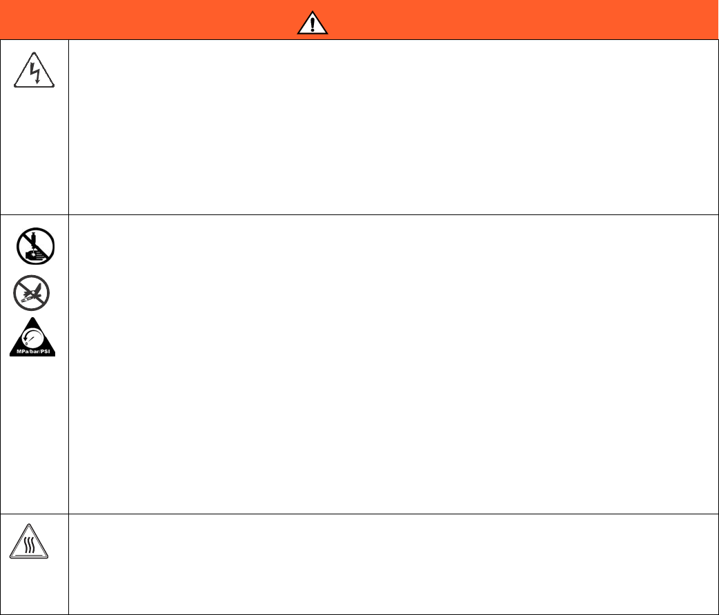
Warnings
The following warnings are for the setup, use, grounding, maintenance, and repair of this equipment. The exclama-
tion point symbol alerts you to a general warning and the hazard symbol refers to procedure-specific risk. Refer back
to these warnings. Additional, product-specific warnings may be found throughout the body of this manual where
applicable.
WARNING
ELECTRIC SHOCK HAZARD
This equipment must be grounded. Improper grounding, setup, or usage of the system can cause elec-
tric shock.
• Turn off and disconnect power at main switch before disconnecting any cables and before servicing
equipment.
• Connect only to grounded power source.
• All electrical wiring must be done by a qualified electrician and comply with all local codes and reg-
ulations.
SKIN INJECTION HAZARD
High-pressure fluid from hose leaks, or ruptured components will pierce skin. This may look like just a
cut, but it is a serious injury that can result in amputation. Get immediate surgical treatment.
• Inspect hose before each use for cuts, bulges, kinks or any other damage.
• Replace hoses proactively at regular intervals based on your operating conditions.
• Replace damaged hose immediately.
• Tighten all fluid connections before operating the equipment.
• Keep clear of leaks.
• Do not stop or deflect leaks with your hand, body, glove, or rag.
• Never exceed hose Maximum Pressure or Temperature ratings.
• Only use chemicals that are compatible with wetted parts. See Technical Data in this manual.
Read MSDSs and fluid and solvent manufacturer’s recommendations.
• Follow the Pressure Relief Procedure when you stop spraying and before cleaning, checking, or
servicing equipment.
BURN HAZARD
Equipment surfaces and fluid that’s heated can become very hot during operation. To avoid severe
burns:
• Do not touch hot fluid or equipment.
Warnings
3A0260H 7
FIRE AND EXPLOSION HAZARD
Flammable fumes, such as solvent and paint fumes, in work area can ignite or explode. To help pre-
vent fire and explosion:
• Use equipment only in well ventilated area.
• Eliminate all ignition sources; such as pilot lights, cigarettes, portable electric lamps, and plastic
drop cloths (potential static arc).
• Keep work area free of debris, including solvent, rags and gasoline.
• Do not plug or unplug power cords, or turn power or light switches on or off when flammable fumes
are present.
• Ground all equipment in the work area. See Grounding instructions.
• Use only grounded hoses.
• Hold gun firmly to side of grounded pail when triggering into pail.
• If there is static sparking or you feel a shock, stop operation immediately. Do not use equipment
until you identify and correct the problem.
• Keep a working fire extinguisher in the work area.
EQUIPMENT MISUSE HAZARD
Misuse can cause death or serious injury.
• Do not operate the unit when fatigued or under the influence of drugs or alcohol.
• Do not exceed the maximum working pressure or temperature rating of the lowest rated system
component. See Technical Data in all equipment manuals.
• Use fluids and solvents that are compatible with equipment wetted parts. See Technical Data in all
equipment manuals. Read fluid and solvent manufacturer’s warnings. For complete information
about your material, request MSDS from distributor or retailer.
• Do not leave the work area while equipment is energized or under pressure. Turn off all equipment
and follow the Pressure Relief Procedure when equipment is not in use.
• Check equipment daily. Repair or replace worn or damaged parts immediately with genuine manu-
facturer’s replacement parts only.
• Do not alter or modify equipment.
• Use equipment only for its intended purpose. Call your distributor for information.
• Route hoses and cables away from traffic areas, sharp edges, moving parts, and hot surfaces.
• Do not kink or over bend hoses or use hoses to pull equipment.
• Keep children and animals away from work area.
• Comply with all applicable safety regulations.
TOXIC FLUID OR FUMES HAZARD
Toxic fluids or fumes can cause serious injury or death if splashed in the eyes or on skin, inhaled, or
swallowed.
• Read MSDSs to know the specific hazards of the fluids you are using.
• Store hazardous fluid in approved containers, and dispose of it according to applicable guidelines.
WARNING

Warnings
83A0260H
PERSONAL PROTECTIVE EQUIPMENT
You must wear appropriate protective equipment when operating, servicing, or when in the operating
area of the equipment to help protect you from serious injury, including eye injury, hearing loss, inhala-
tion of toxic fumes, and burns. This equipment includes but is not limited to:
• Protective eyewear, and hearing protection.
• Respirators, protective clothing, and gloves as recommended by the fluid and solvent manufac-
turer.
WARNING

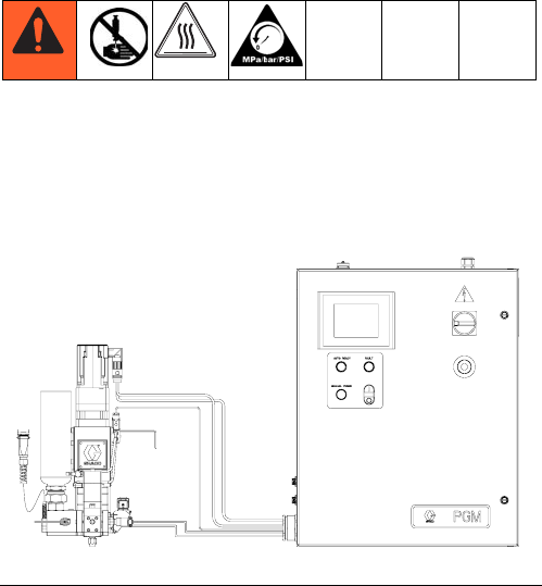
Overview
3A0260H 9
Overview
System Configurations
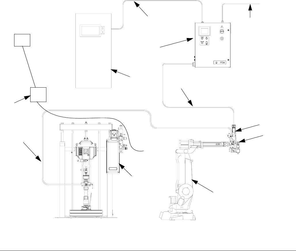
Typical Heated System Installation
Key:
AA *Control Center (User Interface)
AB *Gear Meter Assembly
AC Applicator/Dispense Valve†
AD Automation Robot
AE Automation Interface Cable †
AF *Gear Meter Cables
AG Heated Fluid Supply System
AH Fluid Supply Hose
AJ Heat Control
AK Automation Controller
AL Air Filter Assembly
AM Remote Dispense Hose †
AN Heated Manifold
AO Dynamic Regulator †
*Included
† Accessory
FIG. 1: Typical Heated System Installation
AD
AC
AH AB*
AF*
AA*
AE
AK
AM
AG
Air Supply
Drop Site
AN
Power
AL
AJ
AH
AH
AO
AO
Overview
10 3A0260H
Typical Ambient System Installation
Key:
A *Control Center (User Interface)
B *Gear Meter Assembly
C *Applicator/Dispense Valve
D Automation Robot
E Automation Interface Cable†
F Gear Meter Cables
G Fluid Supply System
H Fluid Supply Hose
J Automation Controller
K Air Filter Assembly
* Included
† Accessory
FIG. 2: Typical Ambient System Installation
G
D
C*
F*
A*
E
H
J
Air Supply
Drop Site
K
Power
B*
Overview
3A0260H 11
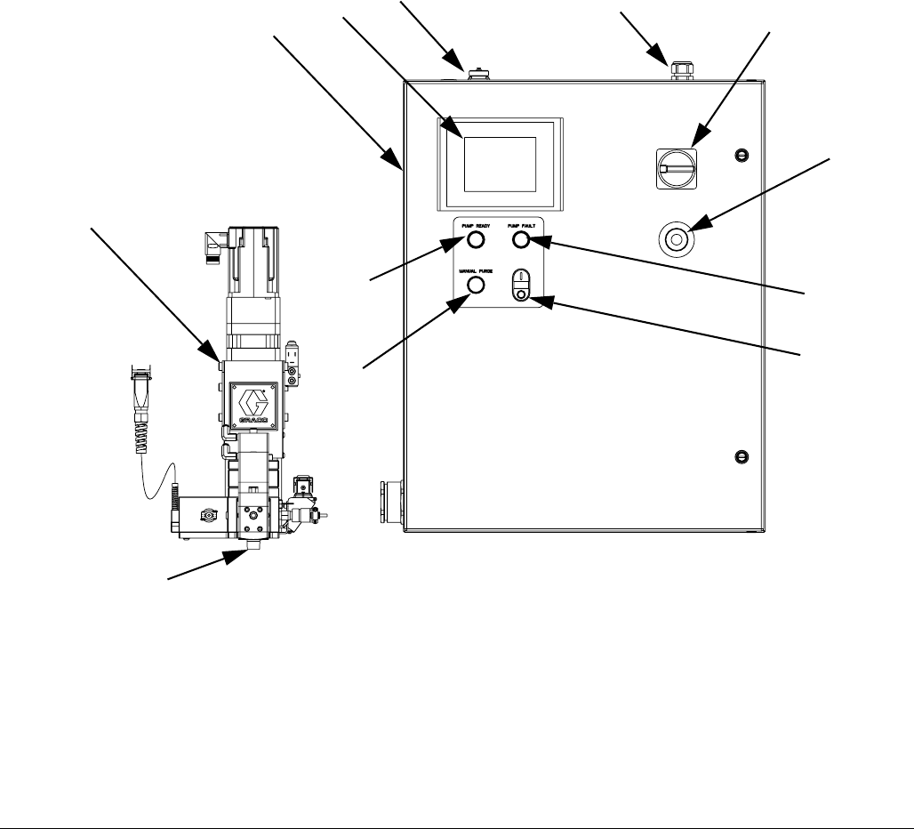
Component Identification
FIG. 3
Key:
1 Gear Meter
2 System Controls Box
3 User-Interface Touch Display
4 External Control Interface
Connections
5 Power Input
6 Main Power Switch
7 Emergency Stop
8 Pump Fault Indicator Light
9 Control Power On/Off buttons
10 Pump Ready Light
11 Manual Purge Button
12 Dispense Valve
1
2345
12
6
7
8
9
10
11
Overview
12 3A0260H
System Overview
The PGM system provides positive displacement meter-
ing for precision bead control. The control accepts auto-
mation signals to provide accurate and consistent output
flow. The gear meter can achieve high flow rates with
high viscosity materials.
Control Power On/Off
Control Power is the power for the signals to the gear
meter which control gear meter rotation. When Control
Power is off, the gear meter cannot rotate.
Pump Ready Light
The Pump Ready light displays when the pump is ready
for Automatic Mode dispensing. When Manual mode is
enabled, this light will not turn on.
Pump Fault Light
The Pump Fault light is illuminated whenever a pump
fault is active.
Manual Purge Button
The Manual Purge button initiates a shot.
Typical Applications
• Solar Panel
• Perimeter Seal
• Desiccant
• Edge Seal
• Automotive Manufacturing
• Window and Door General Assembly
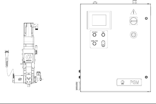
FIG. 4: Control Center Dimensions

Installation
3A0260H 13
Installation
Before Installation
•Have all system and component documentation
available during installation.
•See component manuals for specific data on compo-
nent requirements. Data presented here applies to
the PGM assemblies only.
•Be sure all accessories are adequately sized and
pressure-rated to meet system requirements.
•Use the PGM control center only with the PGM
metering assembly.
Overview
The basic steps to install a PGM system are shown
below. See the separate component manuals for
detailed information on supply systems and dispense
valves.
Installation Steps
1. Mount control center.
2. Connect and ground control center.
3. Mount gear meter assembly.
4. Ground gear meter assembly.
5. Check ground continuity.
6. Connect fluid line between gear meter and dispense
valve. For remote mount dispense valves, con-
nect fluid supply line and air supply to gear meter.
7. Plumb filter assembly near air drop site that will be
used for gear meter assembly.
8. Connect other fluid and air lines to additional system
components as instructed in their manuals.
9. Install cable assemblies.
NOTICE
To avoid damaging the PGM system, use at least
two people to lift, move, or disconnect the system.
The system is too heavy for one person to lift or
move.
Installation
14 3A0260H
Install Control Center
Mount
Ensure the following criteria are met before mounting
the PGM control center:
• Select a location for the control center that allows
adequate space for installation, service, and use of
the equipment.
• For best viewing, the user interface should be
60-64 in. (152-163 cm) from the floor.
• Ensure there is sufficient clearance around the con-
trol unit to run cables to other components.
• Ensure there is easy access to an appropriate elec-
trical power source. The National Electric Code
requires 3 ft. (0.91 m) of open space in front of the
control center.
• Ensure there is easy access to the power switch.
• Ensure the mounting surface can support the weight
of the control center and the cables attached to it.
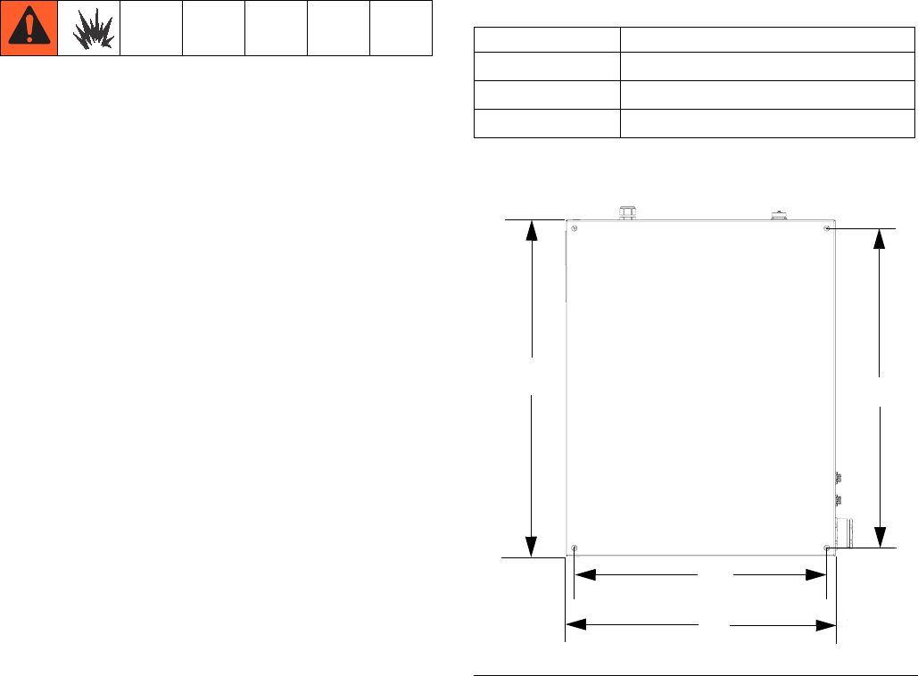
Secure the control center with appropriate size bolts
through the 0.50 in. (13 mm) diameter holes. See the
mounting dimensions in the following table and FIG. 5.
Control Center Assembly Measurement
A24.0 in. (610 mm)
B22.5 in. (572 mm)
C30.0 in. (762 mm)
D28.5 in. (724 mm)
FIG. 5: Control Center Dimensions
A
B
CD
Installation
3A0260H 15
Electrical Connections Install Gear Meter Assembly
To install the PGM metering assembly:
•Mount the gear meter assembly.
•Ground gear meter assembly.
•Connect the gear meter assembly to the control cen-
ter.
•Connect fluid lines and cables.
Mount
Before Mounting Assembly
•See component manuals for specific information on
component requirements. Information presented
here pertains to the PGM gear meter assembly only.
•Have all system and subassembly documentation
available during installation.
•Be sure all accessories are adequately sized and
pressure-rated to meet the system's requirements.
•Use only the Graco PGM gear meter assembly with
the Graco PGM control center.
Mount Assembly
1. Select a location for the gear meter assembly. Keep
the following in mind:
• Allow sufficient space for installing the equip-
ment.
• Make sure all fluid lines, cables and hoses eas-
ily reach the components to which they will be
connected.
• Make sure the gear meter assembly allows the
automation unit to move freely along all axis.
• Make sure the gear meter assembly provides
easy access for servicing its components.
Follow these precautions when grounding, connect-
ing cables, connecting to a power source or making
other electrical connections.
To reduce the risk of fire, explosion, or electric shock:
•The control center must be electrically connected
to a true earth ground; the ground in the electrical
system may not be sufficient.
•A qualified electrician must complete all grounding
and wiring connections.
•For wiring, refer to FIG. 6.
Refer to your local code for the requirements for a
“true earth ground” in your area.
NOTICE
If power and grounding connections are not done
properly, the equipment will be damaged and the
warranty voided.
FIG. 6: 240 Vac Wiring
L2
L1 Ground
Installation
16 3A0260H
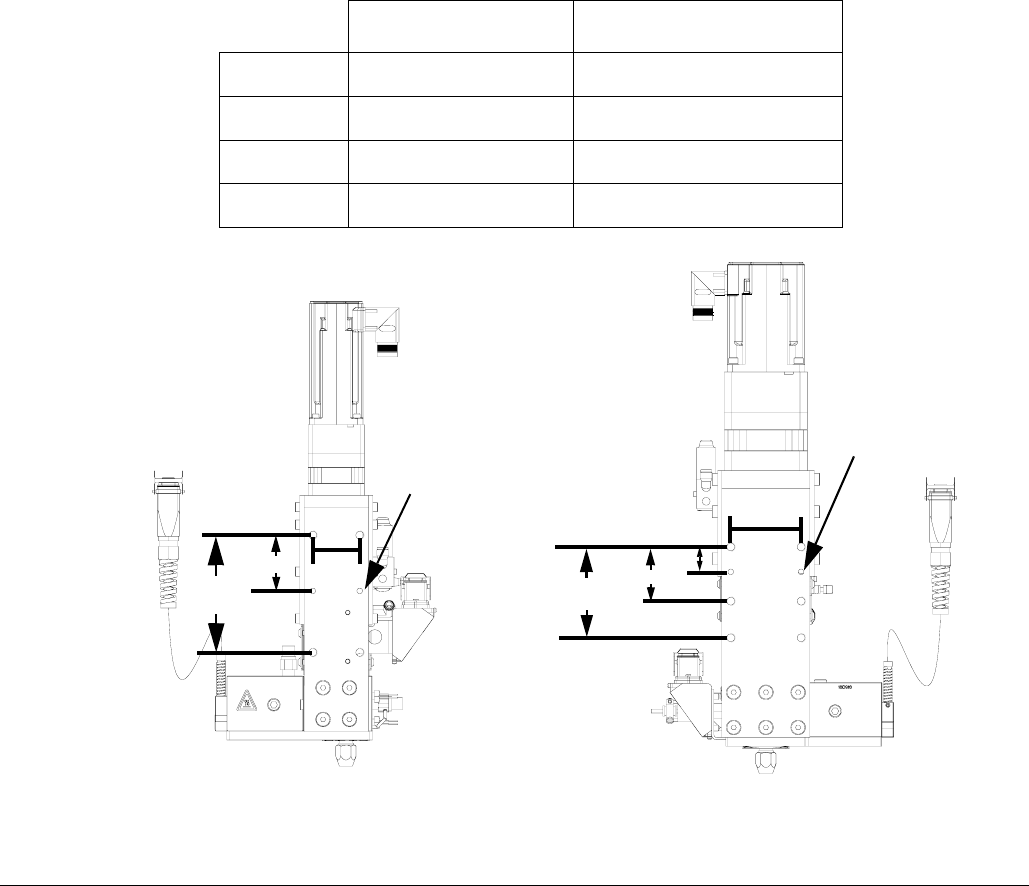
2. Mount and secure the gear meter assembly to the
automation unit (or other mounting surface) with
mounting plate. The mounting plate is tapped with
M10 x 1.5 bolts. Maximum bolt length through plate
is 0.75 in. (19 mm). See the mounting dimensions in
Table 4 and FIG. 7.
Table 4: Gear Meter Assembly Measurement
6 cc Pump 20 cc Pump
A2.00 in. (50.8 mm) 3.00 in. (76.2 mm)
B5.00 in. (127 mm) 3.875 in. (98.43 mm)
C2.375 in. (60.33 mm) 2.313 in. (58.75 mm)
DNA 1.063 in. (27.00 mm)
FIG. 7: Gear Meter Assembly Dimensions
C
B
6 cc Pump 20 cc Pump
A
AD
C
B
0.238 in. (6.0 mm)
diameter
0.238 in. (6.0 mm)
diameter
Installation
3A0260H 17
Grounding
Ground the gear meter assembly as instructed here and
in the individual component manuals. Make sure the
gear meter assembly and its components are installed
correctly to ensure proper grounding.
Air and Fluid Hoses
For static dissipation, use only electrically conductive
hoses or ground the applicator / dispense valves.
Dispense Valve
Follow the grounding instructions in the dispense valve
manual.
Connect Fluid and Air Lines
Follow the instructions in your separate component
manuals to connect air and fluid lines. The following are
only general guidelines.
•The PGM gear meter assembly should be installed
on the automation unit or in another appropriate
place, as close as practical to the dispense valve.
• For a remote mount dispense valve, connect a
fluid line between the gear meter outlet and the dis-
pense valve. Shorter fluid lines (hoses) will provide
better fluid system response.
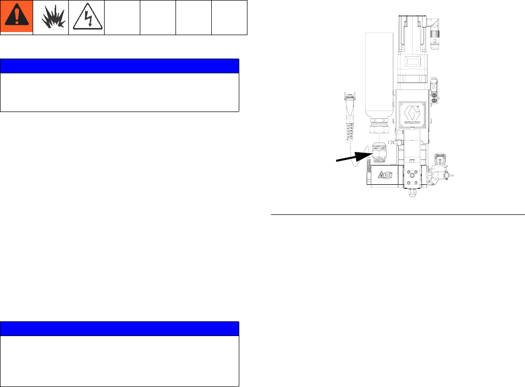
•See page 4 for list of inlet fittings.
•Air must be clean and dry, between 60-100 psi
(0.41-0.68 MPa, 4.14-6.89 bar). Flush air line before
plumbing in air filter assembly (234967). Plumb in air
filter assembly near air drop site (upstream of PGM).
Adding an air regulator to this line will provide more
consistent dispense valve response times.
•Connect a 1/4 in. OD air supply line to the inlet port
on the PGM air supply inlet.
NOTE: To maximize system performance keep the
dispense hose length as short as the application
will allow.
NOTICE
If power and grounding connections are not done
properly, the equipment will be damaged and the
warranty voided.
NOTICE
Route all fluid and air lines carefully. Avoid pinching
and premature wear due to excessive flexing or rub-
bing. Hose life is directly related to how well they are
supported.
FIG. 8: Inlet Fitting
Installation
18 3A0260H
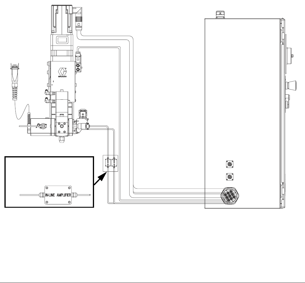
Install Cable Assemblies
1. Connect servo motor power and feedback cables.
2. Connect pressure transducer cable.
3. Connect dispense valve solenoid cable.
4. Connect heat cables, if equipped, to Therm-O-Flow
controller.
FIG. 9: Cable Installation Diagram
ti22239a
Remote mount amplifier on units
with 15 meter cables only.
System Setup
3A0260H 19
System Setup
Overview
The PGM system compensates for temperature, flow, or
pressure fluctuations. However, if there is a hardware
change on the supply system or the dispense material is
changed, the PGM system must be setup again.
After material is loaded into the supply system, set up
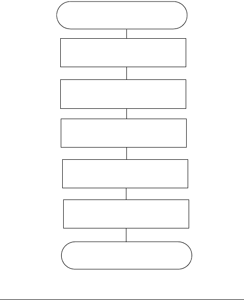
the PGM system using the Setup screens. FIG. 10
shows the major system setup steps. The following sub-
sections provide instructions to complete each setup
step. Once these steps are complete the module is
ready for operation.
NOTE: See Appendix A - User Interface Display on
page 81 for detailed operating instructions for each
user interface screen.
FIG. 10
System Setup
Configure Control Settings (
page 20)
Configure Mode Settings (
page 20)
Configure Delay Settings (
page 21)
Adjust Pressure Sensors (
page 21)
Configure Errors (
page 22)
End System Setup
System Setup
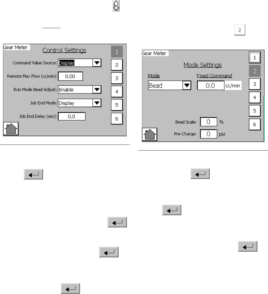
20 3A0260H
Configure Control Settings
Set the controls for the dispense source, how dispense
commands are sent, and auto mode settings.
1. From the Home screen, select the Setup icon
.
NOTE: The Setup screens are password protected.
Enter password “PGM10”to access the following
screens.
2. Press the drop-down list for Command Value
Source and select Display or Remote. Press
Enter to confirm selection.
3. If Command Value Source is set to Remote, enter
the Remote Max Flow (cc/min) for the 10 VDC com-
mand source.
4. Press the drop-down list for Run Mode Bead Adjust
and select Enable or Disable. Press Enter
to confirm selection.
5. Press the drop-down list for Job End Mode and
select Display or Remote. Press Enter to
confirm selection.
6. If Job End Mode is set to Display, press Job End
Delay Display field and enter desired delay time in
seconds. Press Enter to confirm.
Configure Mode Settings
Set the dispense mode (bead or shot). The bead scale
and pre-charge are also adjustable from the Mode Set-
tings screen.
NOTE: See Appendix A - User Interface Display on
page 81 for a description of each feature.
1. With the system in setup mode,
press
to navi-
gate to the Mode Settings screen.
2. Press the drop-down list for Mode. Select Bead or
Shot. Press Enter to confirm selection.
3. If Command Value Source is set to Display, press
the drop-down list for Fixed Command Flow Rate
then enter the flow rate in cc/min. Press
Enter to confirm. See Configure Control
Settings for instructions to set the Command Value
Source value.
4. If Shot Time is displayed, press the drop-down list
for Shot Time in Seconds. Press Enter to
confirm.
NOTE: Shot Time is only displayed if Dispense Mode
is set to Shot.
FIG. 11 FIG. 12
System Setup
3A0260H 21
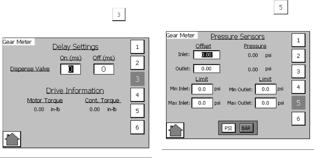
Configure Delay Settings
Set on and off delays (in milliseconds) for the dispense
valve.
1. With the system in setup mode,
press
to navi-
gate to the Delay Settings screen.
2. Press the On Delay field and enter a desired delay
value in milliseconds. Default is zero milliseconds.
3. Press the Off Delay field and enter e desired value
in milliseconds. Default is zero milliseconds.
Adjust Pressure Sensors
Set pressure offsets and pressure limits.
1. With the system in setup mode,
press
to navi-
gate to the Pressure Sensor screen.
2. Set the desired offset for the inlet and outlet pres-
sures. Remove all pressure on the sensors, and
then adjust the offset so the measured value
reads 0.
NOTE: Offsets are set at the factory.
3. Set the desired minimum and maximum pressure
limits for the inlet and outlet.
NOTE: These values may need changed after the
system has gone through the Startup procedure.
FIG. 13
FIG. 14
System Setup
22 3A0260H
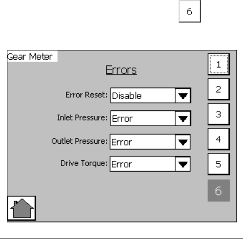
Configure Errors
Set the error type (error or deviation) that will be issued
if the pressure or drive torque goes outside the set high
and/or low limits. See Appendix A - User Interface
Display on page 81 for information on the purpose of
each error type.
NOTE: When an alarm is set to Error the machine
will be disabled when the alarm occurs.
1. With the system in setup mode,
press
to navi-
gate to the Errors screen.
2. Press the Error Reset drop-down list and select
Enable or Disable.
3. Press the Inlet Pressure drop-down list and select
Error or Deviation.
4. Press the Outlet Pressure drop-down list and select
Error or Deviation.
5. Press the Drive Torque drop-down list and select
Error or Deviation.
FIG. 15
Operation
3A0260H 23
Operation
Startup
Initial Startup
1. Ensure the PGM control enclosure and all of the
proper connections to and from the control enclo-
sure have been made. Ensure fittings are tight.
2. Read and understand the Operation and User Inter-
face sections of this manual.
3. Continue startup with Step 2 in Standard Startup.
Standard Startup
1. Carefully inspect the entire system for signs of leak-
age or wear. Replace or repair any worn or leaking
components before operating the system.
2. Press the Stop button on the control enclosure.
3. Turn on air and electrical power to the system.
4. Turn on the main power to supply power to the
PGM.
5. Check Interface Signals: If this is a new installa-
tion, power on each system input and verify that
each input is being received. See Appendix B - I/O
on page 95.
6. Turn on the material supply system.
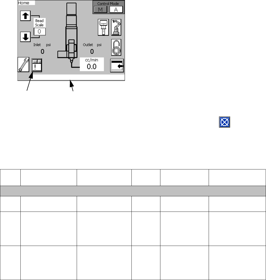
Load Material
Before using the system material must be loaded into
the supply system.
1. If this is a new installation, follow the Initial Startup
procedure. Otherwise, follow the Standard Startup
procedure.
2. Turn on the fluid supply pressure to the fluid inlet
block for the PGM.
3. Place the dispense valve over a waste container.
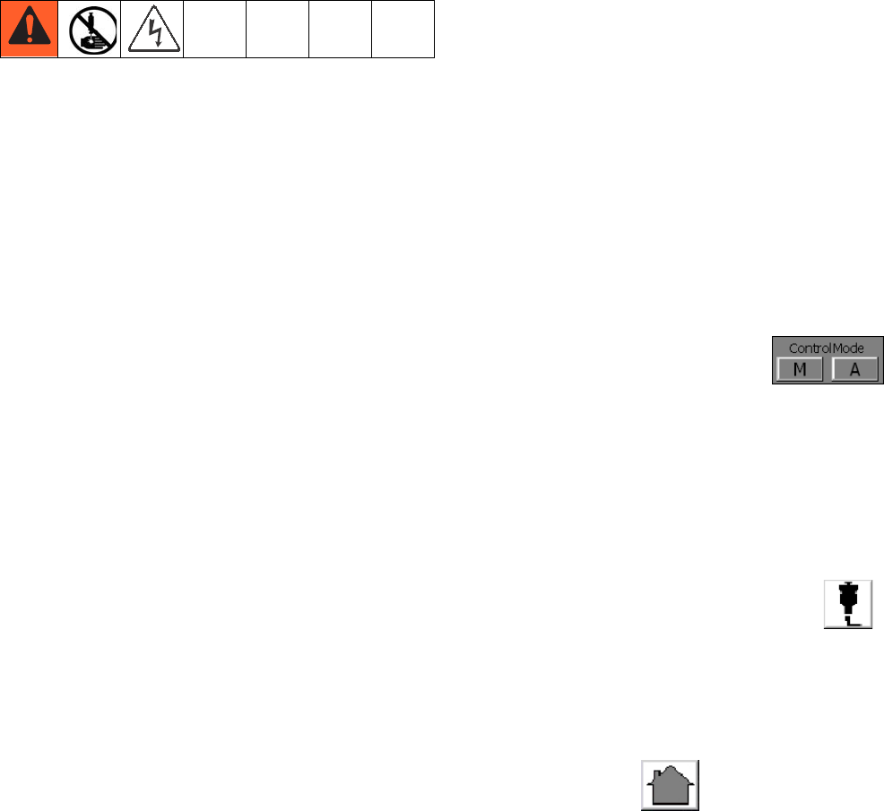
4. Navigate to the Maintenance screen. See Screen
Navigation Diagram on page 81 in the Appendix
A - User Interface Display section.
5. Select Manual (M) Control Mode .
6. Enter the minimum flow rate to prime the system.
See the following table.
7. Press and hold the dispense valve icon . Dis-
pense fluid until clean, air-free fluid flows from the
dispense valve.
NOTE: The manual purge button on the user-inter-
face panel can be used to prime the system.
8. If desired, press to navigate to the Home
screen.
Pump Size
cc / revolution
Min Flow Rate
cc / minute
612
20 40

Operation
24 3A0260H
Maintenance Mode Operation
Operating from maintenance mode enables the pump to
begin dispensing when the user presses . Dis-
pense parameters and duration depend on the selected
control.
Verify System Operation
Use maintenance mode to manually check the operation
of the PGM system components before switching over to
automation control (normal operation).
NOTE: Perform any of the following procedures
while in maintenance mode.
Set Inlet Pressure
The inlet pressure reading should be in the range of
300 psi (2.1 MPa, 21 bar) to 1500 psi (10.3 MPa,
103 bar). The recommended inlet pressure should be
500 psi (3.4 MPa, 34 bar) lower than the outlet pressure.
Follow steps in the supply system manual to set the inlet
pressure.
Feed System Pressure Drop
During material flow, the PGM inlet pressure decreases.
The amount the pressure decreases is the amount of
pressure lost between the feed pump and the PGM inlet.
With high viscosity fluids, long line lengths, or small
diameter line sizes this pressure decrease can be thou-
sands of psi (hundreds of bar). This means that the
static pump pressure is set much higher than the PGM
needs at its inlet. To prevent excessive static pressure at
the inlet of the PGM, a dynamic regulator is recom-
mended on air motor supply air. During dispense the
normal pump regulator is active. During a stalled condi-
tion the dynamic regulator is active.
Dispense Weight Verification
1. From maintenance screen, select Shot mode.
2. Enter a 10 second shot time.
3. Enter the desired flow rate.
4. Record a minimum of 5 shot weights.
5. If shot weights are inconsistent check feed pressure
or reduce flow rate and repeat shot test.
NOTE: Regular weight checks are recommended to
ensure system is performing properly.
NOTICE
Excessive inlet pressure will cause accelerated
wear on the gear meter seals and the pump feed
system.
Operation
3A0260H 25
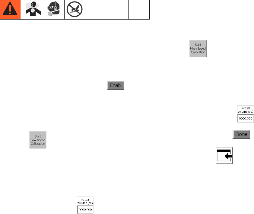
Calibration
1. Perform Startup procedure, page 23. Verify all sys-
tem components are at desired pressures and tem-
peratures. Adjust as desired.
2. Navigate to the Calibrate screen. See Screen Navi-
gation Diagram on page 81 in the Appendix A -
User Interface Display section.
3. Press the Enable Calibration button .
4. Weigh one disposable container and tare the scale.
5. Place container below dispense tip.
6. Press the Start Low Speed Calibration
button .
7. Weigh the container.
8. Divide the weight of the dispensed material by the
specific gravity to determine the volume.
9. Enter the volume into the Low Speed Calibration
Actual Volume input box .
10. Weigh a second disposable container and tare the
scale.
11. Place container below dispense nozzle.
12. Press the Start High Speed Calibration
button .
13. Weigh the container.
14. Divide the weight of the dispensed material by the
specific gravity to determine the volume.
15. Enter the volume into the High Speed Calibration
Actual Volume input box .
16. Press the Done button .
17. If desired, press to navigate to the Main
screen.
Operation
26 3A0260H
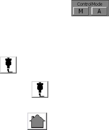
Dispense from Maintenance
Screen
1. Navigate to the Maintenance screen. See Screen
Navigation Diagram on page 81 in the Appendix
A - User Interface Display section.
2. Select Manual (M) Control Mode .
3. From the Mode drop-down menu, select Bead or
Shot Mode.
Manually Dispense Fluid
1. Press and verify the dispense valve opens.
2. Continue to press as long as needed to load
or dispense material. Release to stop dispensing.
3. If desired, press to navigate to the Home
screen.

Operation
3A0260H 27
Automation Control (Normal)
Operation
During automation control (normal operation) the PGM
automatically dispenses when it receives a command
from the automation unit.
NOTE: See Appendix B - I/O on page 95.
To enter Auto mode, select Auto (A) Control
Mode .
Typical Automation Cycle
In order for the system to run it must be in Auto mode.
Before a cycle begins the robot outputs should have the
following values:
• Job Complete: 0
• Dispense Trigger: 0
A typical cycle consists of the following dispensing
sequence.
1. The robot checks that Dispenser Ready signal is set
to On (High). If On, a cycle can begin.
2. If command source is set to Remote, robot sends
0-10 VDC Flow Rate signal.
NOTE: See Setup Screen 1 information in the
Appendix A - User Interface Display section begin-
ning on page 81.
3. Robot turns on dispense trigger.
4. PGM turns on In Cycle.
5. Robot removes dispense trigger.
6. If Job Complete is set to Remote, robot turns on Job
Complete.
7. Robot removes Job Complete before starting the
next cycle.
NOTE: In the event of a deviation alarm, the Dis-
pense Ready signal will remain on along with the
alarm signal. In the event of an error alarm, the Dis-
pense Ready signal will turn off and the alarm signal
will remain on.
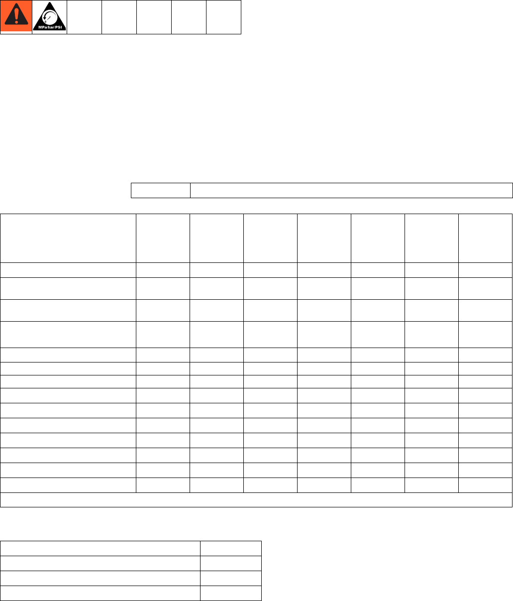
Pressure Relief Procedure
28 3A0260H
Pressure Relief Procedure
1. Shut off the fluid supply to the PGM inlet block.
2. If equipped, place a waste container beneath the
fluid drain valve under the filter.
3. Place a waste container beneath the dispense
valve.
4. Slowly open the drain valve at each fluid filter to
relieve fluid pressure. Close valve when pressure
gauge reads zero.
5. Navigate to the Maintenance screen. See Screen
Navigation Diagram on page 81 in the Appendix
A - User Interface Display section.
6. Perform the following steps to perform a low flow
dispense:
a. From the Mode drop-down menu, select Bead
mode.
b. Enter the minimum flow rate for your system.
For example, 12 cc/min or 40 cc/min depending
on the size of the gear meter.
c. Press or the Purge button on the control
enclosure to begin the low flow dispense.
d. Continue to dispense until the inlet pressure on
the PGM is near zero.
e. Visually locate the plug installed at the back of
the inlet block.
f. Place a container under the plug and slowly
remove the plug to relieve remaining inlet pres-
sure.
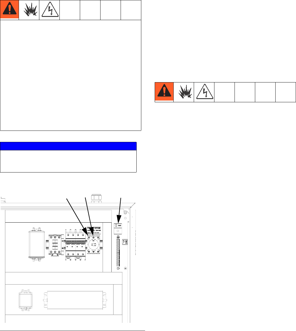
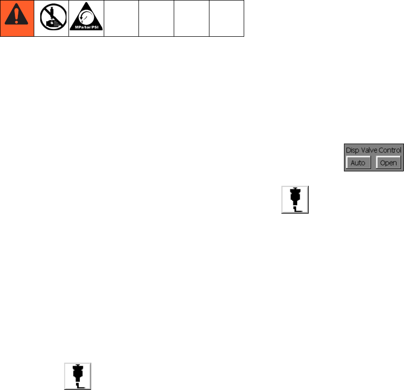
7. In maintenance mode, select Open Dispense Valve
Control mode , which opens the dis-
pense valve. Press the manual dispense button
until fluid flow stops.
Pressure Relief Procedure
3A0260H 29
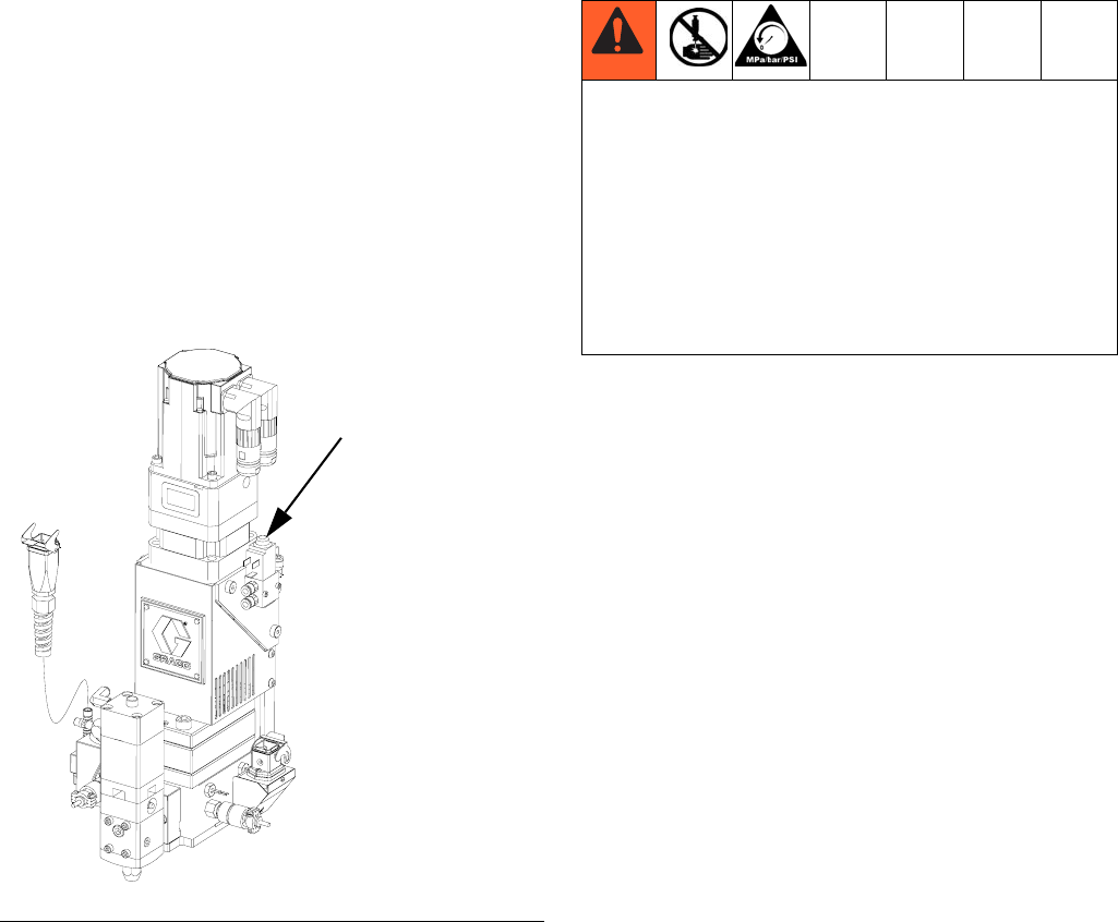
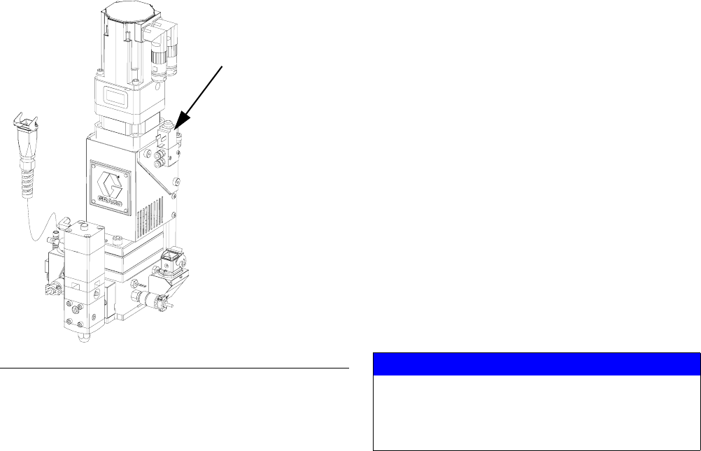
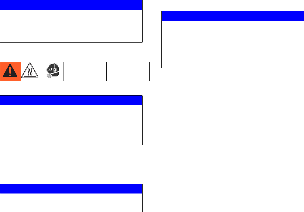
8. If the dispense device cannot be actuated from the
control center, refer to FIG. 16 and perform the fol-
lowing steps to open the dispense valve and relieve
fluid pressure:
a. Manually actuate the plunger on the solenoid,
that opens the dispense valve to relieve fluid
pressure. Refer to FIG. 16.
b. Continue actuating the plunger until all pressure
is purged from the system between the needle
and dispense valve before proceeding to the
next step.
9. Shut off power and air to the fluid supply system.
FIG. 16: Dispense Valve Air Solenoid
Dispense Valve
Air Solenoid
If you have followed the previous steps and still sus-
pect that a valve, hose, or dispense nozzle is clogged
or that pressure has not been fully relieved, very slowly
remove the dispense tip, clean the orifice, and con-
tinue relieving pressure.
If this does not remove the obstruction, very slowly
loosen the hose end coupling and relieve pressure
gradually, then loosen the coupling completely. Clear
the valves or hose. Do not pressurize the system until
the blockage is cleared.
Shutdown
30 3A0260H
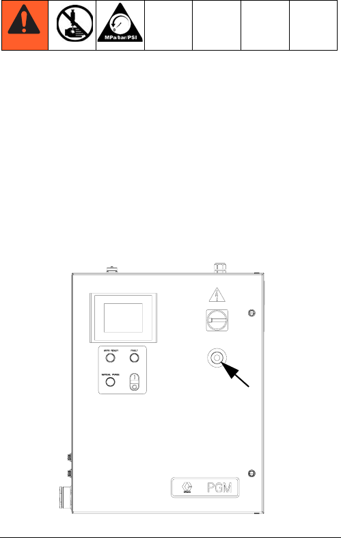
Shutdown
1. Press the Stop button. See FIG. 17.
2. Shut off the material supply to the gear meter/meter.
3. Shut off heat to PGM. See related manuals section
for Therm-O-Flow manual and Accessory Heat Con-
trol.
4. Shut off power and air to the fluid supply system.
5. Turn off the main power supply.
FIG. 17: Stop Button
Troubleshooting
3A0260H 31
Troubleshooting
NOTE: Check all possible solutions in the chart
below before you disassemble the system.
Refer to Supply Systems manual for additional trouble-
shooting; refer to Related Manuals on page 3. Also
refer to Error Codes and Troubleshooting, page 33.
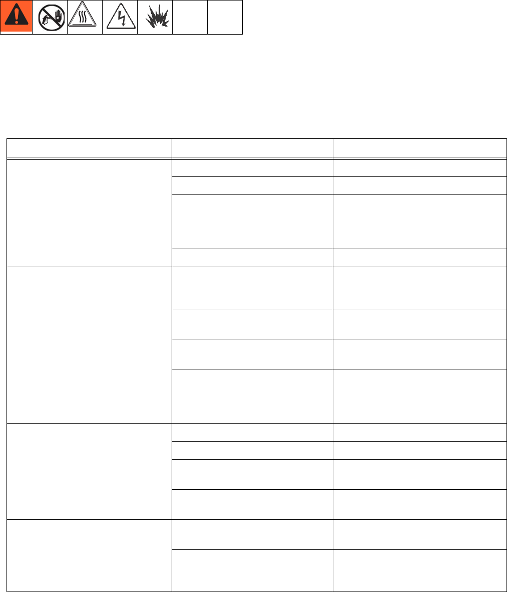
PGM Fluid Assembly
Problem Cause Solution
No Inlet Pressure No air pressure on supply system Verify supply system pressure
Leak in supply system Check supply lines and connections
False signal being sent to control Check inlet pressure sensor output;
verify that it corresponds to zero
pressure; replace sensor and/or
amplifier
Leak at PGM drive shaft Replace drive shaft seals
No Outlet Pressure Dispense motor not rotating Refer to Error code section of the
manual; Cycle power and perform
startup
Dispense Off delay set too long Verify Dispense valve delays in
setup screens
Dispense valve solenoid stuck
open
Verify function of dispense valve
False signal being sent to control Check outlet pressure sensor out-
put; verify that it corresponds to zero
pressure; replace sensor and/or
amplifier
High Outlet Pressure Blocked dispense tip Replace dispense tip
Flow rate too high for application decrease flow rate
Dispense valve On delay set too
long
Verify Dispense valve delays in
setup screens
Dispense valve solenoid stuck
closed
Verify function of dispense valve
Dispense pattern too light Supply pressure too low Verify inlet pressure needed for flow
rate
Flow rate too high for application Perform dispense weight verification,
see Calibration procedure on
page 25; Lower flow rate and repeat
Troubleshooting
32 3A0260H
Dispense Valves
Measured flow does not match
command
Supply pressure too low Verify inlet pressure needed for flow
rate
Flow rate too high for application Perform dispense weight verification,
see Calibration procedure on
page 25; Lower flow rate and repeat
Gear meter is not calibrated Perform calibration; Perform weight
verification, see Calibration proce-
dure on page 25
Gear meter is worn or damaged Perform weight verification, see Cal-
ibration procedure on page 25; if
weights are not repeatable repair or
replace gear meter
Problem Cause Solution
Valve not opening Air not getting to open port Verify air pressure solenoid
No Dispense Trigger signal from
automation unit
Check input from automation unit
Valve not shutting off Air not getting to close port (except
AutoPlus valve)
Verify air pressure to solenoid
Verify solenoid operation
Verify air line routing and connec-
tions
Dispense Trigger signal from auto-
mation unit is on Check input from automation unit
Sluggish open/close Air pressure low Verify air pressure is above 60 psi
(0.4 MPa, 4 bar)
Needle/seat worn Rebuild valve; replace needle/seat
Pressurized material past the valve
shut-off is escaping
Reduce running pressure
Reduce nozzle length
Increase nozzle orifice size
Material leaks from back of valve Shaft seal is worn Rebuild valve; replace seals
Air leaks from dispense valve Loose air connections Check air connections; tighten if
necessary
Worn piston o-ring Rebuild valve; replace piston o-ring
Errors
3A0260H 33
Errors
View Errors
Errors can be viewed from the Home screen or from the
Alarm View screen.
There are three levels or errors: alarms, deviations, and
advisories. Alarms are critical and require immediate
correction; therefore the system automatically shuts
down. Deviations are important and require attention but
not immediately. Advisories are not critical but still
require attention.
NOTE:
•Errors set the dispenser ready signal LOW.
•Advisories and deviations do not set the dispenser
ready signal LOW.
Diagnose Errors
See Error Codes and Troubleshooting for valid error
codes, possible causes, and solutions.
Clear Errors and Reset Control
Unit
From the Alarm View screen, press to clear an
error before restarting the control unit.
NOTE: See the Configure Errors section on page 22.
Error Codes and Troubleshooting
Access the Alarm
View screen Error Message
Error
No. Error Name Error Description
Error
Type Cause Solution
PGM Control Errors
1 Control Power Off Control power has
been removed
Advisory Stop button or
E-stop
Press Control Power
button
2 Inlet Pressure Devia-
tion
Inlet material pres-
sure outside limits
Deviation Feed pressure set
too high or too low.
Limits are not set
correctly
Verify pressure limits
in Setup Screen 5.
Verify supply pres-
sures during dis-
pense.
3 Inlet High Pressure
Error
Inlet material pres-
sure above max limit
Alarm Feed pressure too
high. Limits are
not set correctly.
Verify pressure limits
in Setup Screen 5.
Verify supply pres-
sures during dis-
pense.

Errors
34 3A0260H
4 Inlet Low Pressure
Error
Inlet material pres-
sure below min limit
Alarm Feed pressure too
low. Limits are not
set correctly.
Verify pressure limits
in Setup Screen 5.
Verify supply pres-
sures during dis-
pense.
5 Outlet Pressure Devi-
ation
Outlet material pres-
sure outside limits
Deviation Back pressure is
too high or too low.
Limits are not set
correctly
Verify pressure limits
in Setup Screen 5.
Verify outlet pressures
during dispense.
6 Outlet High Pressure
Error
Outlet material pres-
sure above max limit
Alarm Back pressure is
too high. Limits
are not set cor-
rectly
Verify pressure limits
in Setup Screen 5.
Verify outlet pressures
during dispense.
7 Outlet Low Pressure
Error
Outlet material pres-
sure below min limit
Alarm Outlet pressure
too low. Limits are
not set correctly.
Verify pressure limits
in Setup Screen 5.
Verify outlet pressures
during dispense.
8 Inlet Max Pressure
Fault - Relieve Pres-
sure and Cycle Power
Inlet material pres-
sure exceeds max
rated pressure
Alarm Feed system pres-
sure is set too
high. Pressure
sensor damaged.
Perform pressure
relief procedure.
Change inlet supply
pressure. Cycle
power; Verify Pres-
sure sensor is work-
ing properly.
9 Outlet Max Pressure
Fault - Relieve Pres-
sure and Cycle Power
Outlet material pres-
sure exceeds max
rated pressure
Alarm Dispense valve
not opening. Flow
rate too high.
Material not at
temperature
Perform pressure
relief procedure;
Cycle Power; Verify
Dispense valve func-
tion; Perform weight
check verification;
Reduce flow rate
10 Drive Torque Devia-
tion
Motor exceeds con-
tinuous rated torque
Deviation Flow rate too high.
Dispense Valve
not opening.
Material not at
temperature
Lower flow rate;
reduce outlet pres-
sure drop; Verify
material temperature
11 Drive Torque Error Motor exceeds con-
tinuous rated torque
Alarm Flow rate too high.
Dispense Valve
not opening.
Material not at
temperature
Lower flow rate;
reduce outlet pres-
sure drop; Verify
material temperature
12 Drive Peak Torque
Error - Drive disabled,
Cycle Power
Motor exceeds peek
torque rating
Alarm Flow rate too high.
Dispense Valve
not opening.
Material not at
temperature
Cycle Power Lower
flow rate; reduce out-
let pressure drop; Ver-
ify material
temperature
Error
No. Error Name Error Description
Error
Type Cause Solution

Errors
3A0260H 35
13 Pre-Charge Timeout Pre-Charge Pressure
was not reached
after dispense
Advisory Pre-Charge value
not set correctly
Set Pre-Charge to
zero. Monitor outlet
pressure; Adjust
Pre-Charge pressure
14 High Pressure Inter-
lock OFF
Pressure limit is
bypassed
Advisory Pressure sensors
are disabled
Contact Graco cus-
tomer service
15 Dispense Valve Open
(Auto Default)
Dispense valve is
open
Advisory Dispense valve
open button has
been selected
From the Mainte-
nance screen select
Dispense valve Auto
16 Calibration is enabled
complete calibration
procedure
Calibration mode
enabled
Advisory Calibration
enabled selected
from the calibrate
screen
Complete calibration
procedure
17 Drive Fault, Cycle
Power
Motor drive is dis-
abled
Alarm Various conditions Cycle Power verify
motor torque during
dispense
18 Calibration out of
range
Calibration values
are out of range or
flow rate is too low
for current K factor
Advisory Improper calibra-
tion, flow rate too
low, or pump wear
Perform calibration
procedure
Error
No. Error Name Error Description
Error
Type Cause Solution
Maintenance
36 3A0260H
Maintenance
Prior to performing any maintenance procedures, follow
the Pressure Relief Procedure on page 28.
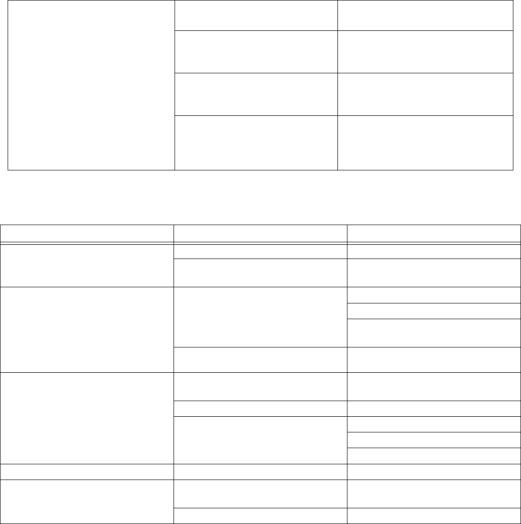
Maintenance Schedule
The following tables list the recommended maintenance procedures and frequencies to operate the equipment safely.
The maintenance is divided between mechanical and electrical tasks. Maintenance must be performed by trained
personnel per this schedule to assure safety and reliability of the equipment.
Mechanical
Electrical
* Check Component Manual for more detailed maintenance information.
Operator Maintenance Person
Task Daily Weekly Monthly 3-6
months
or
125,000
cycles
18-24
months
or
500,000
cycles
36-48
months
or
1,000,000
cycles
As
Required
Inspect system for leaks
Depressurize fluid, after opera-
tion
Remove heat from system,
after operation
Inspect filter (234967) bowls
and drain
Check hoses for wear
Check/tighten fluid connections
Check/tighten air connections
Lubricate dispense valves*
Replace gear meter seals
Rebuild dispense valve*
Replace air filter
Replace Solenoid
Replace gear meter drive shaft
Replace gear head
* Check component manual for more detailed maintenance information.
Task Weekly
Check cables for wear
Verify cable connections
Verify operation of “System Stop” button
Repair
3A0260H 37
Repair
NOTE: Refer to Parts section beginning on page 51
for part reference number identification.
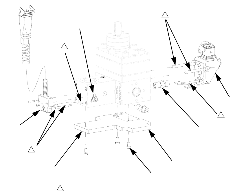
Gear Meter Assembly
This section describes how to remove and replace com-
ponents on the gear meter assembly.
Prepare Gear Meter Assembly for Repair
1. Perform Pressure Relief Procedure, page 28.
2. Disconnect main power at the control box.
3. If present, remove power from the heat control.
4. Remove servo power cable and servo feed back
cable. See gear meter assembly parts; see Parts
section starting on page 51.
5. Remove heat cables.
6. Remove pressure transducer cables and dispense
valve cable.
7. Remove supply air pressure from solenoid.
8. Remove front guard.
9. Remove material hoses if necessary.
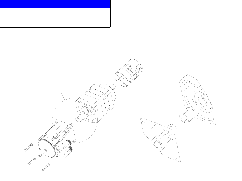
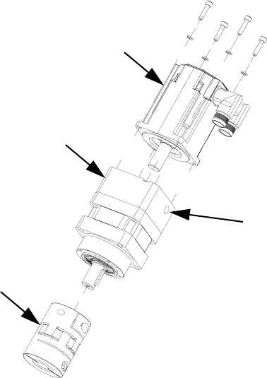
Replace Servo Motor or Gear Head
Replacing either the Servo Motor or Gear Head requires
the following procedure.
Remove Servo Motor and Gearhead
1. Prepare Gear Meter Assembly for Repair,
page 37.
2. Remove support gussets (9, 1106).
3. Remove bolts (1, 1103) connecting top mounting
plate (8, 1105) to vertical mounting plate (10, 1107).
4. Remove servo motor, gear head, and top plate.
Coupling (303, 1203) will separate.
5. Remove coupling half
6. Remove 4 screws (3, 1110) that mount to plate to
gear head.
7. Remove gear head coupling covers (302a, 1202a).
8. Loosen gearhead coupling on gearhead shaft.
9. Remove 4 bolts connecting servo motor to gear-
head.
10. Remove servo motor from gear head.
FIG. 18
Repair
38 3A0260H
Install Servo Motor or Gearhead
1. Remove key from motor shaft.
2. Slide the gear head bushing into the drive coupling
and align slots in drive coupling and bushing. See
FIG. 19.
3. Rotate the drive coupling to align clamping bolts
with access holes.
4. Place motor on work surface with motor shaft facing
straight up then mount the gear head. Mounting the
gear head in any other orientation will usually lead
to misalignment and excessive noise.
5. Pre-torque drive coupling to 0.4 N•m (4 in-lb).
6. Bolt gear head to the motor with fasteners provided.
7. Final toque drive coupling to 8.5 N•m (76 in-lb) in
three steps increasing torque each time.
8. Do not tighten coupling to gear head output shaft
until drive assembly is mounted in frame.
NOTE: Orient servo motor so that the motor connec-
tions do not interfere with material inlet hose.
9. Install gussets with shoulder bolts (5, 1104).
Remove Coupling
1. Prepare Gear Meter Assembly for Repair,
page 37.
2. Remove support gussets (9, 1106).
3. Remove bolts (1, 1103) connecting top mounting
plate (8, 1105) to vertical mounting plate (10, 1107).
4. Remove servo motor, gear head, and top plate.
NOTICE
Use caution when handling servo motor to prevent
damage. Do not use tools that could cause dam-
age.
FIG. 19
SEE DETAIL
A
DETAIL
A
SCALE
3/2
Repair
3A0260H 39
5. Loosen clamping bolts on each side of coupling and
remove coupling.
NOTE: Pump shaft key may fall out during coupling
removal. Secure pump shaft key until coupling is
replaced.
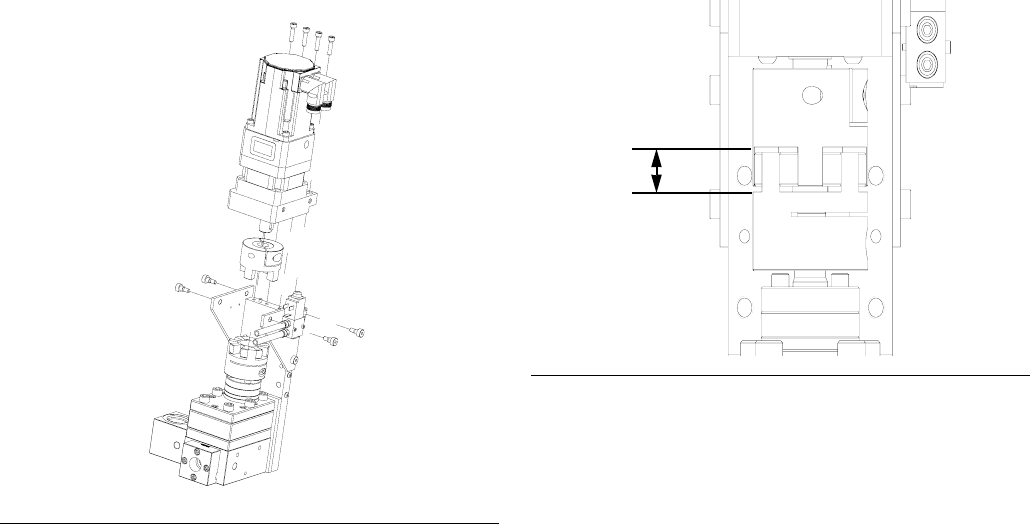
Install Coupling
1. Slide coupling onto gear head output shaft. Tighten
coupling bolt just enough to hold it’s position.
2. Align pump shaft key and slide coupling onto pump
shaft. Tighten coupling bolt just enough to hold it’s
position.
3. Attach servo motor, gear head, and top plate to
pump assembly. See FIG. 20.
4. Slide drive coupling so it is evenly spaced between
pump and gearhead. Both sides of coupling should
slide easily on each shaft. If coupling does not slide
freely loosen pump bolts (103, 1303) and align
pump until coupling moves freely. Tighten pump to
pump block to 430-480 in-lb (48.58-54.23 N•m)
5. Separate coupling until proper gap is created. FIG.
21. See the following table.
6. Tighten coupling bolts to the following torques:
7. Install gussets with shoulder bolts (5, 1104).
FIG. 20
Pump Size
cc / revolution Gap (mm)
618
20 20
FIG. 21
Pump Size
cc / revolution
Torque,
in-lb (N•m)
6 132 (15)
20 309 (35)
Gap
Repair
40 3A0260H
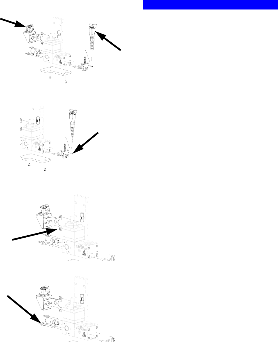
Remove Dispense Valve
1. Prepare Gear Meter Assembly for Repair,
page 37.
2. Manually actuate solenoid to ensure pressure has
been removed.
3. Verify air supply is off.
4. Remove air lines from dispense valve.
5. Remove four dispense valve mounting bolts and
remove dispense valve.
NOTE: For remote mount dispense valves, remove
supply hose at inlet block of dispense valve.
6. Refer to dispense valve manual for complete dis-
pense valve repair instructions; refer to Related
Manuals on page 3.
Install Dispense Valve
1. For direct mounted dispense valves, replace
o-ring (409) if necessary.
2. Align dispense valve with mounting pins on front
block.
3. Install four mounting bolts (408) torque to
50-60 in-lb (5.6-6.7 N•m).
4. Connect air lines.
5. Apply air to the solenoid.
6. Manually shuttle solenoid, see FIG. 22. Verify dis-
pense valve is open when solenoid is depressed.
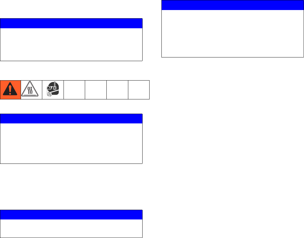
Replace Solenoid
1. Prepare Gear Meter Assembly for Repair,
page 37.
2. Disconnect solenoid cable. Remove mating
screws (405) from gusset.
3. Remove the dispense valve solenoid (410) and
replace it with a new solenoid.
4. Reconnect solenoid cable.
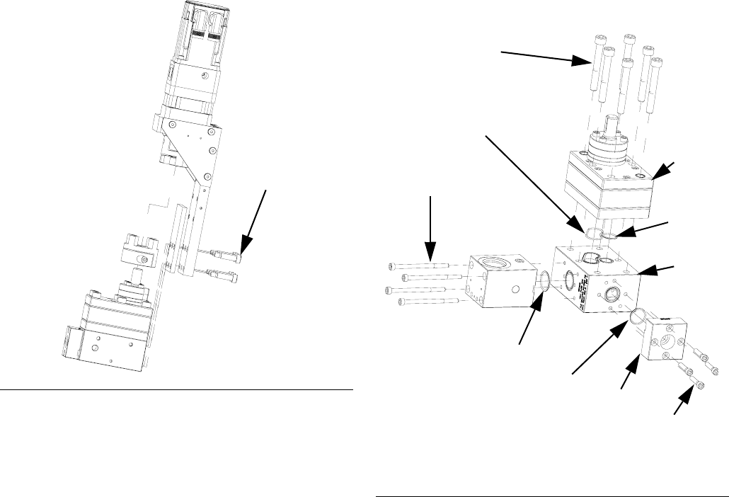
Gear Meter O-Ring Replacement
Refer to Parts section starting on page 51 for o-ring kits.
1. Prepare Gear Meter Assembly for Repair,
page 37.
2. Remove pump block shoulder bolts (4, 1102). See
FIG. 23.
FIG. 22: Dispense Valve Air Solenoid
Dispense Valve
Air Solenoid
NOTICE
Pump section should be fully supported to prevent
damage being dropped. It is recommended that the
gear meter assembly be located on a work bench
for service.
Repair
3A0260H 41
3. Remove drive assembly. See FIG. 23.
4. Perform Remove Dispense Valve procedure.
5. Loosen 4 bolts (407) and remove front block (412).
6. Loosen 4 bolts and remove inlet block (110, 1302).
7. Loosen pump bolts (3, 1303) and remove
pump (108, 1309).
8. Replace front block o-ring (105, 1305).
9. Install front block (412) onto pump block (109,
1308).
10. Replace inlet block o-ring (107, 1306).
11. Install inlet block (102, 1302) onto pump block.
12. Replace pump block o-rings (106, 104; 1304). See
FIG. 24.
13. Place pump (109, 1308) onto pump block. Install
bolts (103, 1303) hand tight.
14. Locate drive assembly on top of pump assembly.
15. Tighten pump block mounting shoulder bolts to
frame (4, 1102).
16. Loosen pump bolts (103, 1303) as needed to
ensure couplings are aligned.
17. Tighten pump bolts to 430 in-lb (48.58 N•m).
18. Replace all electrical connections and fluid connec-
tions before applying fluid pressure and power.
FIG. 23
4, 1102
FIG. 24
*107, 1306
105,
1305*
102, 1302
104, 1304
* Provided in o-ring kit 24E626.
103,
1303
106,
1304
109,
1308
412
407
108,
1309
Repair
42 3A0260H
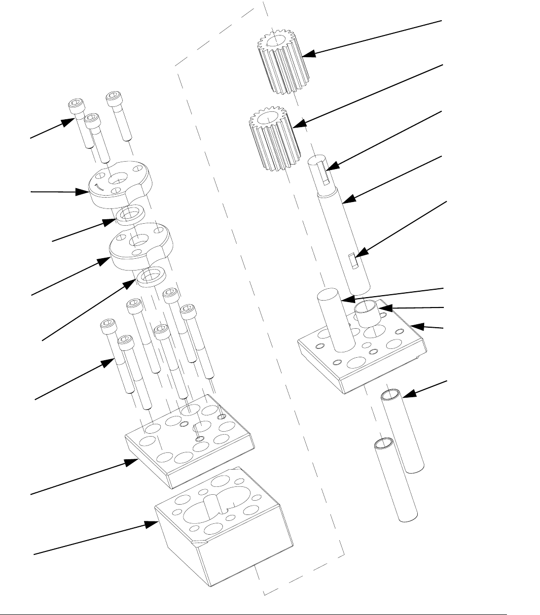
PGM-6 Pump Repair
FIG. 25: PGM-6
1614
1611
1612†
1611
1612†
1613
1601
1602
1607
1608
1615
1605
1609
1604
1606
1603
1610
† Parts included in kit 24E607.
Parts included in kit 24E827.
Parts included in kit 24E826.
(P/N: 125657)
(P/N: 125656)
Repair
3A0260H 43
PGM-6 Pump Disassembly
1. Prepare Gear Meter Assembly for Repair,
page 37.
2. Refer to Gear Pump Maintenance Guide on
page 49 for special notes regarding gear pump
repair.
3. Remove four pump block shoulder bolts (1102).
4. Remove drive assembly. See FIG. 23.
5. Remove seal retainer fasteners (1614) and seal
retainers (1611).
6. Remove pump dowel pins (1610) using an arbor
press.
7. Remove the pump plate screws (1613).
8. Separate the pump front plate (1601), gear case
(1602) and back plate (1603).
NOTE: Notches on the pump plates can be used to
separate the plates.
9. To remove the drive shaft (1605) from the bottom
plate (1603) press the shaft and gear from the bot-
tom pump plate towards the coupling end.
10. To remove the drive gear (1607) from the drive shaft
(1605) Support the drive gear at the lower end to
allow the shaft to be pressed through the gear from
the top or coupling end. Make sure to leave clear-
ance for the drive key.
11. The stud (1606) for the driven gear (1608) is press
fit into the back plate (1603) and need not be
removed if not worn.
12. Clean all components thoroughly before reassem-
bly. The use of an ultrasonic cleaner is recom-
mended.
NOTICE
Pump section should be fully supported to prevent
damage being dropped. It is recommended that the
gear meter assembly be located on a work bench
for service.
NOTICE
Thicker materials may pump heating prior to disas-
sembly. Do not expose the pump to thermal shock.
Raise temperature at a maximum rate of 180°F
(100°C) per hour. Do not exceed 400°F (204°C).
Gradually cool the pump to room temperature.
NOTICE
Do not use a hammer to remove dowel pins as this
will damage the pump.
NOTICE
The PGM pump design relies on a lap fit between
components for performance and sealing. Be care-
ful not to drop the gears (1607, 1608) or damage
the mating surfaces of the pump plates (1601,
1603) and gear case (1602). To prevent damage, do
not use pliers or screwdrivers to remove the gears.
Repair
44 3A0260H
PGM-6 Pump Assembly
1. Place the back plate (1603) on a table inside facing
up.
2. Place the driven gear (1608) on its stud (1606).
3. Place gear case (1602) onto back plate (1603).
Check orientation of dowel pin holes to assure they
align with the ones in the back plate.
4. Slide drive gear (1607) onto drive shaft (1605). Ver-
ify shaft key (1609) is installed properly.
5. Install drive gear (1607) and drive shaft (1605) into
back plate (1603).
6. Position top plate (1601) over drive shaft (1605) and
place onto gear case (1602).
7. Rotate the gears several times to ensure free rota-
tion.
8. Insert the dowel pins (1610) and rotate the gears
several times to ensure free rotation.
NOTE: Dowel pins are not a press fit and may be
installed using a plastic hammer if necessary.
9. Install pump plate screws (1613) and tighten to
85-105 in-lb (9.6-11.8 N•m).
10. Rotate the gears several times to ensure free rota-
tion.
11. Apply a heat resistant, non-evaporating lubricant to
the seal area of the drive shaft (1605).
12. Install new seals (1612). See FIG. 26 and FIG. 27.
13. Install seal retainers (1611) and seal retainer screws
(1614). Tighten screws to 85-105 in-lb
(9.6-11.8 N•m).
14. Align pump shaft key and slide coupling onto pump
shaft. Tighten coupling bolt just enough to hold it’s
position.
15. Attach servo motor, gear head, and top plate to
pump assembly. See FIG. 20.
16. Separate coupling until proper gap is created. See
FIG. 21.
17. Tighten pump block mounting shoulder bolts to
frame (1102).
18. Replace all electrical connections and fluid connec-
tions before applying fluid pressure and power.
NOTICE
Do not hammer or force components together or
damage may occur. Parts will drop into place if
properly cleaned and aligned. Use of a compatible
oil is recommended during assembly.
FIG. 26: Seal Locations
FIG. 27: Seal Orientation
1515,
1614
1512,
1611
*1513,
1612
Pump Body

Repair
3A0260H 45
Repair
46 3A0260H
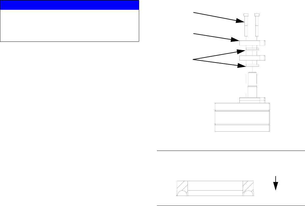
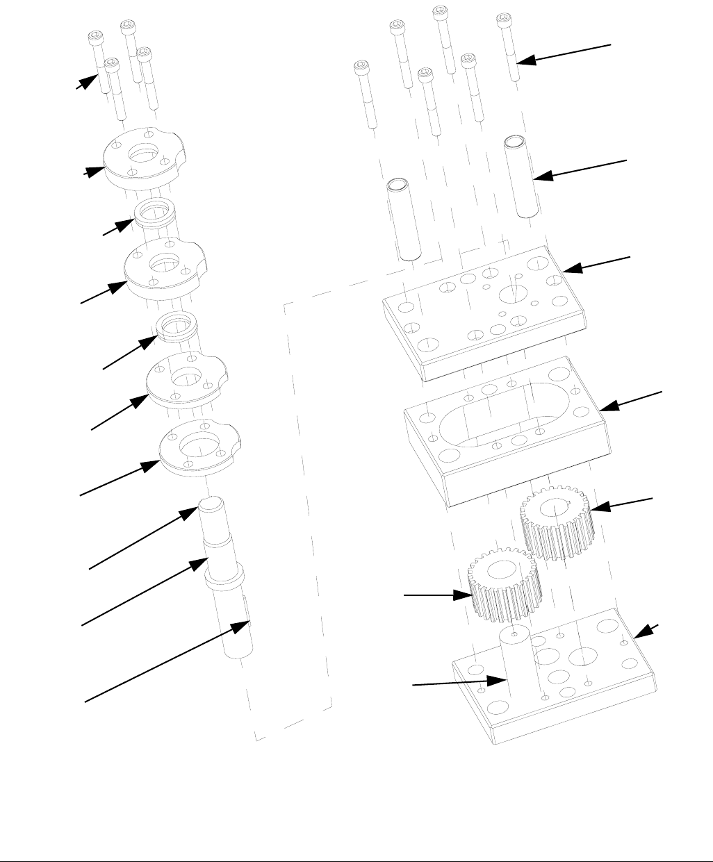
PGM-20 Pump Repair
FIG. 28: PGM-20
1515
1512
1513
†
1512
1513
†
1511
1510
1504
1508
1516
1514
1509
1501
1502
1506
1503
1507
1505
† Parts included in kit 24E619.
Parts included in kit 24E825.
Parts included in kit 24E824.
(P/N: 125655)
(P/N: 125654)
Repair
3A0260H 47
PGM-20 Pump Disassembly
1. Prepare Gear Meter Assembly for Repair,
page 37.
2. Refer to Gear Pump Maintenance Guide on
page 49 for special notes regarding gear pump
repair.
3. Remove six pump block shoulder bolts (4).
4. Remove drive assembly. See FIG. 23.
5. Remove seal retainer fasteners (1515) seal retain-
ers (1512), spacers (1510) and (1511).
6. Remove pump dowels (1509) using an arbor press.
7. Remove the pump plate screws (1514).
8. Separate the pump front plate (1501), gear case
(1502) and back plate (1503).
NOTE: Notches on the pump plates can be used to
separate the plates.
9. To remove drive shaft (1504) from the drive gear
(1506) several flat spacers 1/8 in. (3 mm) thick will
be needed. These will provide clearance for the
drive shaft key (1508) and the top plate (1501).
10. Support pump top plate (1501) and press drive shaft
(1504) through drive gear (1506). Stop when there
is enough clearance between the drive gear (1506)
and top plate (1501) to insert one spacer. Be sure to
allow clearance for drive key (1508).
11. Continue pressing the drive shaft (1504) and insert-
ing spacers until the shaft is free from the drive gear
(1506).
12. The stud (1505) for the driven gear (1507) is press
fit into the back plate (1503) and need not be
removed if not worn.
13. Clean all components thoroughly before reassem-
bly. The use of an ultrasonic cleaner is recom-
mended.
NOTICE
Pump section should be fully supported to prevent
damage being dropped. It is recommended that the
gear meter assembly be located on a work bench
for service.
NOTICE
Thicker materials may pump heating prior to disas-
sembly. Do not expose the pump to thermal shock.
Raise temperature at a maximum rate of 180°F
(100°C) per hour. Do not exceed 400°F (204°C).
Gradually cool the pump to room temperature.
NOTICE
Do not use a hammer to remove dowel pins as this
will damage the pump.
NOTICE
The PGM pump design relies on a lap fit between
components for performance and sealing. Be care-
ful not to drop the gears (1607, 1608) or damage
the mating surfaces of the pump plates (1601,
1603) and gear case (1602). To prevent damage, do
not use pliers or screwdrivers to remove the gears.

Repair
48 3A0260H
PGM-20 Pump Assembly
1. Place back plate (1503) on a table inside face up.
2. Install the driven gear (1507) on stud (1505).
3. Place gear case (1502) onto back plate (1503).
Check orientation of dowel pin holes to assure they
align with the ones in the back plate.
4. Place the top plate (1501) on its edge on a table.
Pass the drive shaft (1504) through the top plate
from the seal side so that the boss on the shaft rests
on the top plate.
5. Rotate the drive shaft (1504) to position the drive
key slot at the top. Insert the drive key (1508) and
driven gear (1506)
6. Grasp the top plate (1501), drive shaft (1504) and
driven gear (1506) to prevent them from separating
and carefully lower them into position onto the gear
case (1502).
7. Rotate the gears several times to ensure free rota-
tion.
8. Insert the dowel pins (1509) and check again for
free rotation.
NOTE: Dowel pins are not a press fit and may be
installed using a plastic hammer if necessary.
9. Install pump plate screws (1514) and tighten to
85-105 in-lb (9.6-11.8 N•m).
10. Rotate the gears several times to ensure free rota-
tion.
11. Apply a heat resistant, non-evaporating lubricant to
the seal area of the drive shaft (1504).
12. Install new seals (1513). See FIG. 26 and FIG. 27.
13. Install spacers (1510, 1511), seal retainers, (1512)
and seal retainer screws (1515). Tighten screws to
85-105 in-lb (9.6-11.8 N•m).
14. Align pump shaft key and slide coupling onto pump
shaft. Tighten coupling bolt just enough to hold it’s
position.
15. Attach servo motor, gear head, and top plate to
pump assembly. See FIG. 20.
16. Separate coupling until proper gap is created. See
FIG. 21.
17. Tighten pump block mounting shoulder bolts to
frame (4).
18. Replace all electrical connections and fluid connec-
tions before applying fluid pressure and power.
NOTICE
Do not hammer or force components together or
damage may occur. Parts will drop into place if
properly cleaned and aligned. Use of a compatible
oil is recommended during assembly.
Repair
3A0260H 49
Gear Pump Maintenance Guide
Review these guidelines prior to performing any mainte-
nance on the pumps.
• Do not run pump dry.
• Do not pull from a vacuum or negative suction head.
• Do not flush with water or other non-lubricating fluid.
• Do not pump corrosives, abrasives and/or fluids car-
rying particles that may harm the pump.
• Do not heat or cool pump faster than 180°F (100°C)
per hour
• Do not drop disassembled parts on a hard surfaces
and do not let parts knock together.
• Never strike the pump parts with an iron hammer.
The parts are designed to drop in place if properly
aligned. Use arbor press to insert or remove press
fit components.
• Do not use pliers to lift the gears.
• Never use a screwdriver to pry the gears upward.
• Apply clean oil or compatible fluid during assembly.
Repair
50 3A0260H
Installing new heater units and RTD sensors
1. Prepare Gear Meter Assembly for Repair,
page 37.
2. Disconnect the power cables from the heaters.
3. Remove two M3 screws to remove the kit from the
inlet block.
4. Remove two M6 screws to remove the kit from the
pump block.
5. Remove the two M8 heater nuts and M6 sensor nut.
6. Remove the heaters and sensor from the block.
7. Clean any residue from both heater and sensor
ports.
8. Installation is the reverse of removal.
NOTICE
The heaters may be difficult to remove and removal
depends on the system type. To ensure proper heat
transfer and to avoid premature heater failure,
System with through hole:
Press out the heater element using an 0.125”
(3 mm) diameter pin.
System without through hole:
Drill out the heater element using a 5mm (0.203 in.)
drill bit. Do not increase the hole dia mt er.
Parts
3A0260H 51
Parts
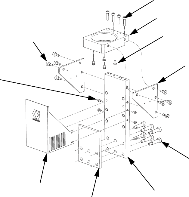
PGM-20 Mounting Frame
12
11
10
9
3
8
1
4
2
5
ti21285a
Ref Part Description Qty
1 124164 SCREW, shcs, M6-1.0 x 25 4
2 124165 SCREW, bhcs, M5-0.6 x 10 4
3 124166 SCREW, bhcs, M6-1.0 x 10 4
4 124167 SCREW, shoulder, 10x30, M8-1.25 6
5 124168 SCREW, shoulder, 8 x 6, M6-1.0 8
8 16D840 PLATE, mounting 1
9 16D841 GUSSET 2
10 16D842 PLATE 1
11 16D843 INSULATOR 1
12 16V444 GUARD, drive 1
Parts
52 3A0260H
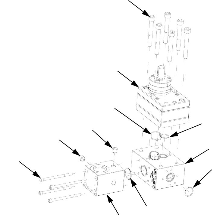
PGM-20 Lower Assembly Block
† Part included in o-ring kit 24E626.
* For part breakdown and repair kits, refer to PGM-20
Pump Repair, page 46.
103
108
104
101
101
102
105
109
106
107
110
Ref Part Description Qty
101 101970 PLUG, pipe, headless 2
102 124173 SCREW, M6-1.0 x 90 4
103 124174 SCREW, M10-1.5 x 75 6
104† O-RING 1
105† PACKING, o-ring 1
106† PACKING, o-ring 1
107† PACKING, o-ring 1
108* 16D827 METER, gear, precision, 20cc/rev 1
109 16D915 BLOCK, pump, mounting 1
110 16D916 BLOCK, inlet, PGM 1
Parts
3A0260H 53
PGM-20 Pump Heat Kit
Replacement Danger and Warning labels, tags, and
cards are available at no cost.
203 201
202
1
3
204 1
1
Ground location.
3
206
206
205
Ref Part Description Qty
201 117764 SENSOR, pressure 2
202 24E412 KIT, heat, pump, PGM-20 1
203 24E413 KIT, heat, PGM, inlet 1
204125363 LABEL, heat/burn, warning 2
205 16D923 INSULATOR 1
206 124175 SCREW 3
Parts
54 3A0260H
PGM Drive - 20 cc Pump
301
302
303
302a
Ref Part Description Qty
301 16D947 MOTOR, PGM drive, servo, 4
frame
1
302 16D946 GEAR REDUCER, PGM drive,
50:1, 80mm frame
1
302a COVER 1
303 16D945 COUPLING, PGM drive, 18x20mm,
w/key
1
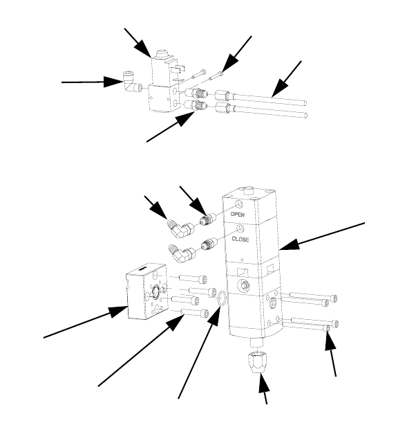
Parts
3A0260H 55
Endure Dispense Valve Fix Mounted
410
403
405 412
404
409
411
402
406
401
408
406
407
Ref Part Description Qty
401 597151 FITTING, elbow, 1/4 tube x 1/8 NPT, male 1
402 117820 SCREW, cap, socket head, M3 2
403 124200 SCREW, socket head cap screw, M6-1.0 x 30,
stainless steel
4
404 124201 SCREW, socket head cap screw, M5-0.8 x 60,
stainless steel
4
405 116768 PACKING, o-ring 1
406 124403 FITTING, adapter, 1/8 NPTM x 03 JICM, mild steel 4
407 124405 SWIVEL, elbow, 90 deg, 03 JICF x 03 JICM, mild
steel
2
408 198446 VALVE, dispense, closer 1
409 244907 VALVE, endure 1
410 16D943 BLOCK, mounting 1
411 16E899 HOSE, assembly, stainless steel braid, 3/16 x 12 2
412 C32089 RETAINER, seat 1
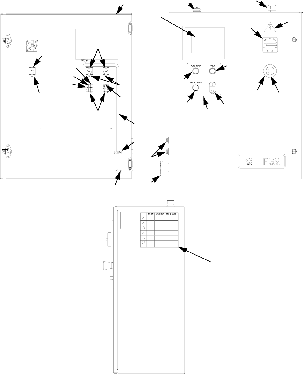
Parts
56 3A0260H
Gear Meter Assembly Panel
651
603
617
614
614
616
614
615
615
616
617
622, 625
618
626, 612
609
608
606
604
605
602, 623
611, 612, 613 610
620 619
601
607
624
652

Parts
3A0260H 57
Replacement Danger and Warning labels, tags, and
cards are available at no cost.
Cables
Ref Part Description Qty
601 ENCLOSURE, control, gear meter
painted
1
602 24F386 MODULE, HMI, PGM 1
603 121148 HANDLE, disconnect, electric 1
604 81/2060-
P/11
BUTTON, dual, grn/red, w/pl-wht 1
605 81/2065-
R/11
BUTTON, operator, pl, red 1
606 81/2065-
G/11
BUTTON, operator, pl, green 1
607 LABEL, legend, panel, PGM 1
608 16D363 BUTTON, operator, pb, flush, black1
609 FITTING, bulkhead, gland, 9wire 1
610 GRIP, cord, .35-.63, 3/4 1
611 81/1060-
14/25
CONNECTOR, sq, 14pw/key, 7a,
panel m
1
612 96/0360/
99
FASTENER, shc, 4-40x0.25, ms, e 12
613 COVER, dust, amp17 conn w/chain1
614 81/2070/
11
LATCH, operator 4
615 81/2080-
1/11
CONTACT, block, no 2
616 81/2072-
2/11
LIGHT, led, white, 24vdc, latch 3
617 81/2081-
1/11
CONTACT, block, nc 2
06 81/1096-
IC2/25
ADAPTER, db9, hmi to plc, s7200,
mxm
1
619 81/2060-
E/11
BUTTON, mush, maint, twist, red 1
620 81/2060-
EL/11
LABEL, legend, e-stop, 60mm 1
622 81/1096-
IC1/11
CABLE, ribbon, db9, m-f, 6ft 1
623 81/1097-
CV6/11
COVER, PET, 6", operator inter 1
62484/0130-
23/11
LABEL, prot earth(grnd).375x.375 1
625 STRAP, wrap, spiral, 1/2'', nylon 4
626 81/1060-
4/25
CONNECTOR, sq, 4p w/key, 7a,
panel m
2
651196548 LABEL, caution 1
65215M511 LABEL, warning,
english/spanish/french
1
Ref Part Description Qty
Description 3 Meter 6 Meter 9 Meter 15 Meter
Servo Power Cable 124251 124252 124253 127280
Feedback Cable 124254 124255 124256 127281
Dispense Valve 24E571 24E572 24E573 24U020
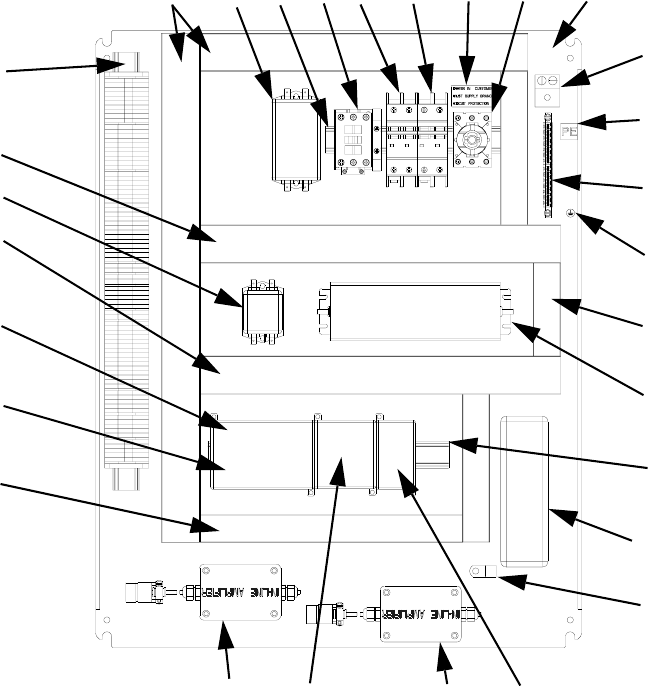
Parts
58 3A0260H
PGM Back Panel
718, 720
716, 720
718, 720
716
709 717 706 707 731 702, 707 701
704
729
705
728
719, 721
710, 725
715, 723, 724
727
718, 720
726, 728 717
714722*722*
712, 730
713
708
711
Ref Part Description Qty
701 PANEL, back, for30x24 encl,
conduit
1
702 123361 SWITCH, disconnect, 32a 1
703 124228 EXTENSION, disconnect,
230-350mm
1
704 117666 TERMINAL, ground 1
705 U70077 TERMINAL, lug, ground, bus type 1
706 123298 CIRCUIT, breaker, 2p, 20a, ul489 1
707 123296 CIRCUIT, breaker, 2p, 1a, ul489 1
708 123359 RELAY, contactor, 30a, 3p, 24vdc
co
1
709 124064 FILTER 1
710 121808 POWER SUPPLY, 24vdc, 4.0a,
100w
1
711 123718 FILTER, emi, 6a, spade con 1
712 24F323 MODULE, plc, s7-200, 14di/10do,
24dc
1
713 124223 MODULE, analog in, s7-200, 4ai,
10dc
1
714 124224 MODULE, ana-out, s7-200, 2aq,
10dc
1
715 24F324 DRIVE, indexer (PGM-06 only) 1
24F325 DRIVE, indexer (PGM-20 only) 1
716 STRIP, terminal, PGM, control 1
717 RAIL, din 1
718 WIREWAY, panduit, 1.5""x3.0""x6' 6
719 WIREWAY, panduit, 1"x3"x6' 6
720 COVER, panduit, 1.5""x6' 6
721 WIREWAY, cover, panduit, 1"x6' 6
Ref Part Description Qty
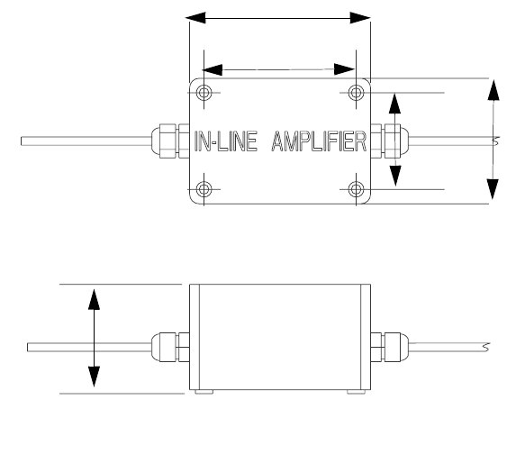
Parts
3A0260H 59
Replacement Danger and Warning labels, tags, and
cards are available at no cost.
* Inline amplifiers are not mounted on panel controls
with 15 m cables.
Remote Mount Amplifiers
Only for control centers with 15 m cables.
Mount
1. Remove cover.
2. Insert #8 machine screws or equivalent (not pro-
vided) into cover mounting holes.
722 124265 AMPLIFIER, signal conditioner,
PGM (3, 6, or 9 m cables)
2
*127279 AMPLIFIER, signal conditioner,
PGM (15 m cable)
2
723 124292 HARNESS, PGM, 26pin dsub, 24
awg
1
724 24D853 HARNESS, wire, power, motor
control
1
725 120997 CABLE, turck, rs 4t-4 1
726 DOCUMENT, schematic, PGM 1
727 CLAMP, wire, harness, 1/4,
galvaniz
1
Ref Part Description Qty
72884/0130-
23/11
LABEL, prot earth (grnd).375x.375 1
72984/0130-
26/11
LABEL, pe 1
730 81/1096-
B/11
BATTERY, backup, 200 day, s7200
plc
1
Ref Part Description Qty
1.9 in.
(50 mm)
2.5 in.
(65 mm)
3.1 in.
(79 mm)
3.7 in.
(94 mm)
2.2 in.
(56.5 mm)
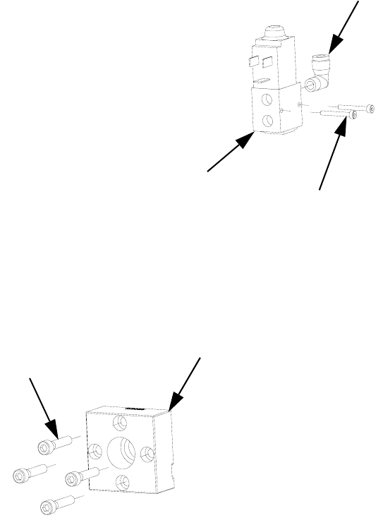
Parts
60 3A0260H
PGM Remote Dispense Valve
809
807
808
805
804
Ref Part Description Qty
804 FITTING 1
805 117820 SCREW, cap, socket head, M3 2
807 124200 SCREW, shsc, M6-1.0 x 30, stain-
less steel
4
808 198446 VALVE, dispense, closer 1
809 16E055 BLOCK, outlet, PGM, 3/4 NPTF,
stainless steel
1
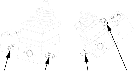
Parts
3A0260H 61
PGM Transducer
901901901
20 cc Pump 6 cc Pump
901
Ref Part Description Qty
901 117764 SENSOR, pressure 2
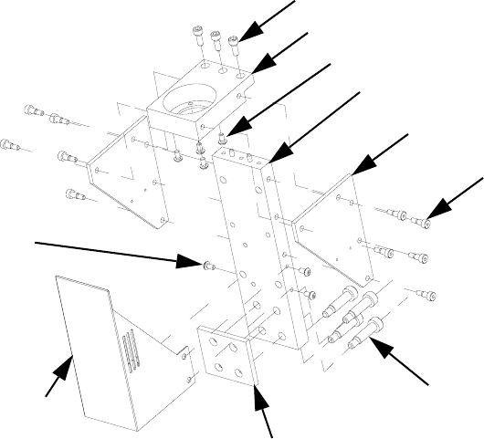
Parts
62 3A0260H
PGM-6 Mounting Frame
1107
1103
1105
1106
1104
1102
1108
1109
1101
1101
Ref Part Description Qty
1101 124165 SCREW, bhcs, M5-0.8 x 10, stain-
less steel
7
1102 124167 SCREW, shoulder, 10 x 30,
M8-1.25, stainless steel
4
1103 124313 SCREW, shcs, M6-1 x 16 mm,
stainless steel
3
1104 124314 SCREW, shoulder, 6 x 8, M5 - 0.8,
carbon steel
8
1105 16E327 PLATE, mounting, drive, PGM-6 1
1106 16E328 GUSSET, drive, PGM-6 2
1107 16E329 PLATE, mounting, pump, PGM-6 1
1108 16E330 INSULATOR, pump, PGM-6 1
1109 16E331 GUARD, drive, PGM-6 1
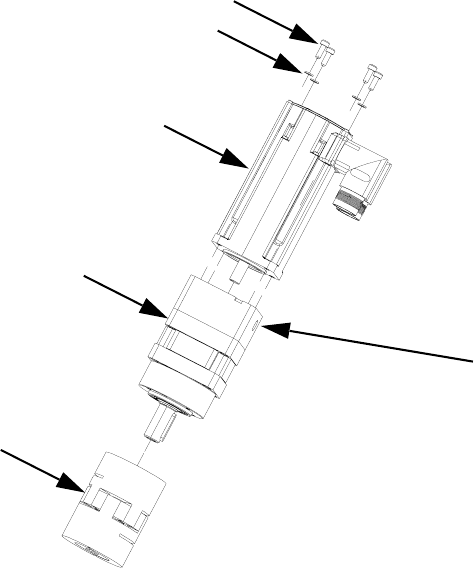
Parts
3A0260H 63
PGM-6 Drive Kit
1203a
1203b
1203
1202
1201
1202a
Ref Part Description Qty
1201 16E367 COUPLING, PGM drive, 12 mm x
14 mm, with key
1
1202 16E368 GEAR REDUCER, PGM drive,
50:1, 60 mm frame
1
1202a COVER 1
1203 16E369 MOTOR, PGM drive, frame 1
1203a SCREW 4
1203b WASHER 4
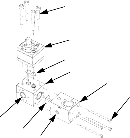
Parts
64 3A0260H
PGM-6 Lower Assembly Block
† Parts are available in o-ring kit 24E677.
* For part breakdown and repair kits, refer to PGM-6
Pump Repair, page 42.
1303
1309
1304
1308
1302
1307
1301
1305
1306
Ref Part Description Qty
1301 101970 PLUG, pipe, headless 2
1302 124173 SCREW, shcs, M6-1.0 x 90, stain-
less steel
4
1303 124174 SCREW, shcs, M10- 1.5 x 75,
stainless steel
4
1304† PACKING, o-ring 2
1305† O-RING 1
1306† PACKING, o-ring 1
1307 16D916 BLOCK, inlet, PGM 1
1308 16E340 BLOCK, pump mounting, PGM-6 1
1309* 24E832 METER, gear, precision, 6cc/rev 1
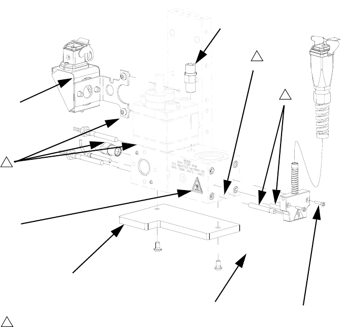
Parts
3A0260H 65
PGM-6 Pump Heat Kit
Replacement Danger and Warning labels, tags, and
cards are available at no cost.
1
3
1401
1405
1402
Ground location.
3
1406 1403
1
1404
Ref Part Description Qty
1401 117764 SENSOR, pressure 2
1402 24E732 KIT, heat, pump, PGM-6 1
1403 24E413 KIT, heat, PGM, inlet 1
1404125363 LABEL, heat, warning 2
1405 16E366 INSULATOR 1
1406 124166 SCREW 2
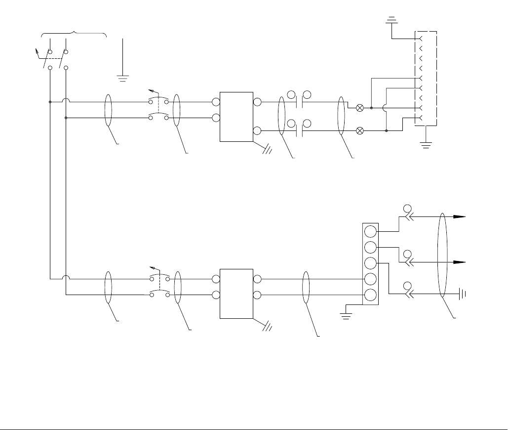
Schematics
66 3A0260H
Schematics
FIG. 29: Schematics, Page 1 of 10
140
149
147
145
142
110
138
136
134
132
130
128
126
124
122
120
118
114
116
112
108
106
104
102
100
141
148
144
146
143
111
139
137
135
133
131
129
127
125
123
121
119
115
117
113
109
107
105
103
101
50-60HZ
1PH/
230V/
DISC-1
L21L2
L11L1
GND
1L1
CB5
1L1
1L2
1L2
1L1
CB1A
1L1
1L21L2
20A
5A
110
111
100
101
GND
FIL-1
LOAD
LINE
102
103
GND
FIL-2
LOAD
LINE
112
113
4
3
2
1
J1
AC
POWER
7
6
5
9
8
GND
L2 240/120 VAC HOT
L1 240/120 VAC N
L3
C1 CNTRL VAC
C2 CNTRL VAC
+BUS
-BUS
REGEN
PE
PS-1
N
24V DC
L
FG
V-
V+
130
125
104
105
HARNESS 24D853
10 AWG
10 AWG
12 AWG
16 AWG
DC COM
CRM
12
CRM
34
BRN
BLU
2
PG-PS1
3
PG-PS1
HARNESS 120997
1
PG-PS1
12 AWG
CABLE FROM PS-1
WHT
BLU
BRN
CUSTOMER MUST SUPPLY BRANCH CIRCUIT PROTECTION
CASE GROUND
P
N
P
N
P
N
P
N
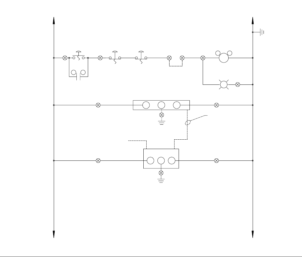
Schematics
3A0260H 67
FIG. 30: Schematics, Page 2 of 10
190
199
197
195
192
160
188
186
184
182
180
178
176
174
172
170
168
164
166
162
158
156
154
152
150
191
198
194
196
193
161
189
187
185
183
181
179
177
175
173
171
169
165
167
163
159
157
155
153
151
PROGRAMMING
IF1A
+24V
IF2 IF1B
0V
G
HMI-1
CAB-1
NOTE: SET SWITCHES
FOR DP/MPI
0X
PB-1
I
CRM
56
125
CONTROL POWER
140
PORT 0 OF PLC-1
CRM
A1 A2
PLC-1
L+
DC/DC/DC
GM
CONTROL_PWR
ON
PL-3
W
130
0
PB-1A
XO
24
VDC
125 130
REMOTE STOP
125
125
130
130
130
125 130
141 142 143
143
DC COM
PB-2
XO
E-STOP
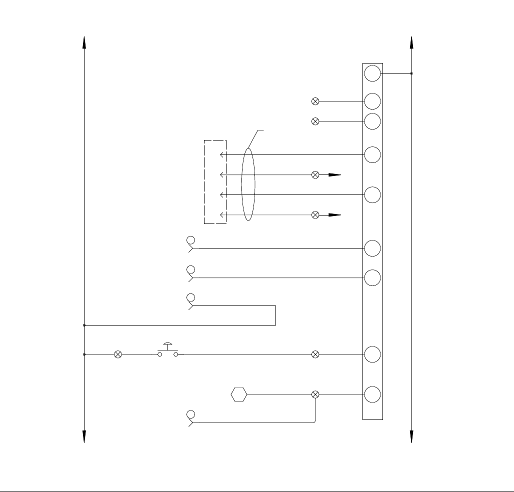
Schematics
68 3A0260H
FIG. 31: Schematics, Page 3 of 10
I0.2
I0.0
200
24
VDC
125 130
PLC-1
INPUTS
1M 130
6
HARNESS
124292
I0.1
202
26 PIN MALE
HIGH DENSITY
7
8
9
125
204 DRIVE-1
FAULT
125
24VDC+
125
206
125
24VDC+
I0.3 DRIVE-1
FAULT
I0.4 AUTOMATION
START
208
I0.5
210
AUTOMATION
JOB COMPLETE
I0.6
212
I0.7
310
MANUAL START
CONTROL POWER
XXX XXX
D-SUB
DRIVE-1 I/O
240
249
247
245
242
210
238
236
234
232
230
228
226
224
222
220
218
214
216
212
208
206
204
202
200
241
248
244
246
243
211
239
237
235
233
231
229
227
225
223
221
219
215
217
213
209
207
205
203
201
1
2
5
125
DC COM
PG-IO
PG-IO
PG-IO
SPARE
SPARE
ORG
ORG
ORG
0X
PB-3
MANL-PURGE
125
358
14
PG-IO
ORG 310
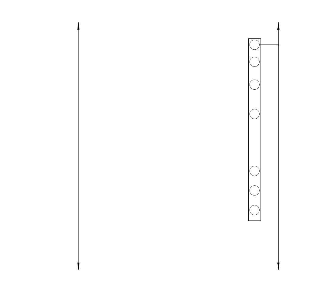
Schematics
3A0260H 69
FIG. 32: Schematics, Page 4 of 10
I1.2
I1.0
24
VDC
125 130
PLC-1
INPUTS
2M 130
I1.1
I1.3
I1.4
I1.5
125 130
DC
COM
258
265
263
260
256
254
252
250
259
266
262
264
261
257
255
253
251
267
268
279
298
296
294
292
290
287
283
285
281
277
275
273
271
269
280
299
297
295
293
291
289
284
286
282
278
276
274
272
270
288
SPARE
SPARE
SPARE
SPARE
SPARE
SPARE
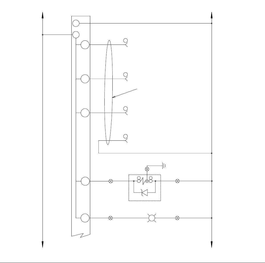
Schematics
70 3A0260H
FIG. 33: Schematics, Page 5 of 10
Q0.4
125
24VDC
Q0.3
Q0.2 304
Q0.1 302
Q0.0 300
130
GEARMETER
FAULT
PLC-1
OUTPUTS
1M
1L+
130
DC
COM
READY TO
DISPENSE
GEARMETER
R
FAULT
PL-2
GEARMETER FAULT
308
DISPENSE
VALVE
OPEN
IN CYCLE
GEARMETER
306
125 130
125 130
11
10
12
6
130 24VDC
COMMON
310
319
317
315
312
308
306
304
302
300
311
318
314
316
313
309
307
305
303
301
329
336
334
331
326
324
322
320
330
337
333
335
332
328
325
323
321
327
348
346
344
342
340
338
349
347
345
343
341
339
130
PG-IO
PG-IO
PG-IO
PG-IO
SOL-DV
+
1
RED
-
2
WHT
BLK
USE ORANGE WIRE
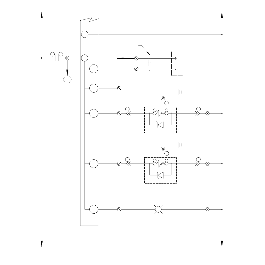
Schematics
3A0260H 71
FIG. 34: Schematics, Page 6 of 10
GEARMETER READY
G
READY
PL-1
320
125
Q0.7
Q0.5
Q0.6
2L+
310
24VDC DC
COM
Q1.1
Q1.0
2
26 PIN MALE
HIGH DENSITY
D-SUB
1
130
130
312
DC COM
312
314
316
HARNESS
124292
DRIVE-1 I/O
DRIVE-1
ENABLE
PRIMARY A
DYNAMIC REGULATOR
125 130
125 130
130
2M 130
CRM
13 14
285
318
SOL-B
BLK +
1
RED
-
2
WHT
PG-B
2
PG-B
1
3
TANDEM B
130
378
387
385
383
380
376
374
372
370
368
366
364
362
360
358
356
352
354
350
379
386
382
384
381
377
375
373
371
369
367
365
363
361
359
357
353
355
351
391
398
396
393
389
392
399
395
397
394
390
388
SOL-A
BLK +
1
RED
-
2
WHT
PG-A
2
PG-A
1
3
130
SPARE
DYNAMIC REGULATOR
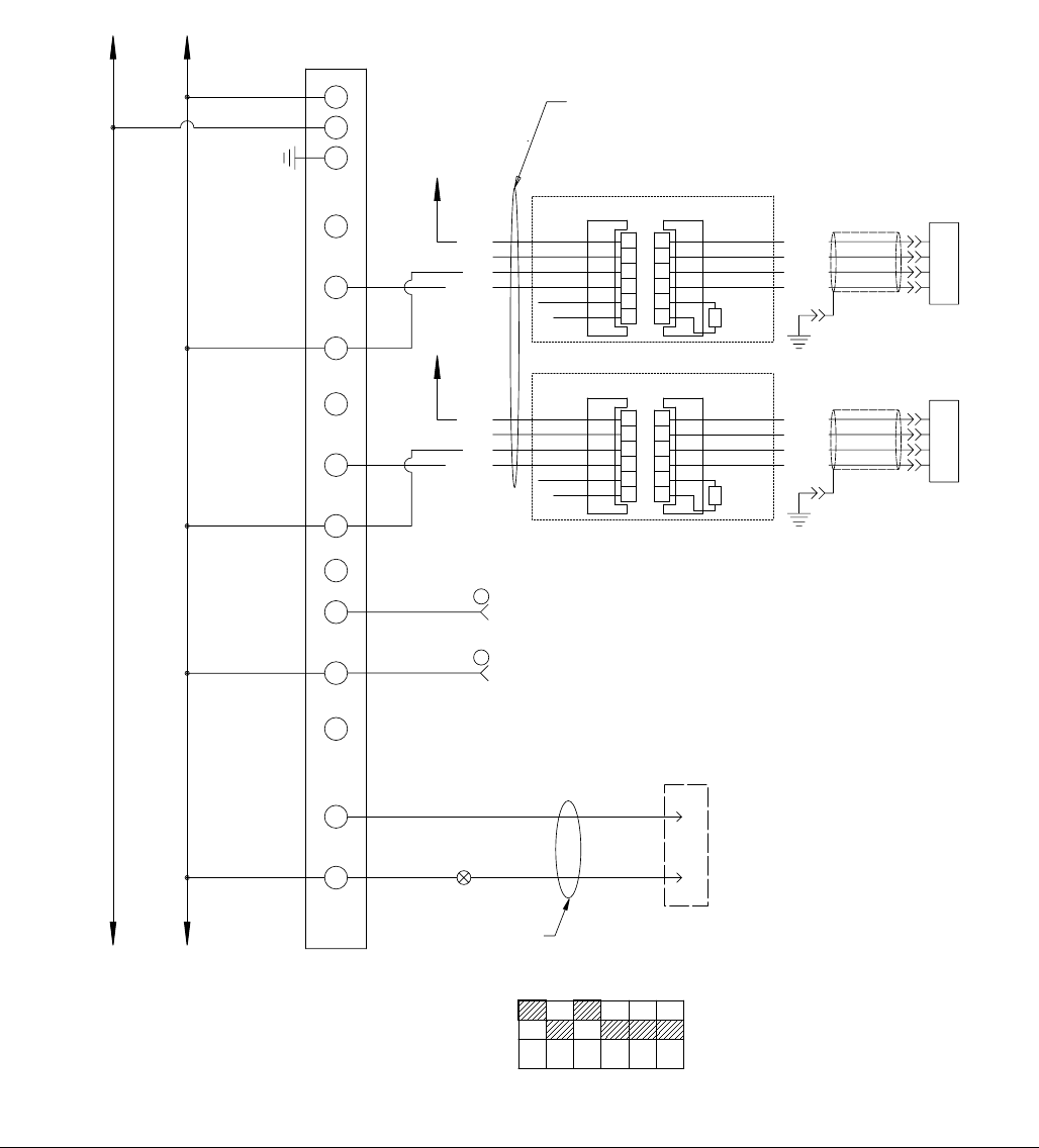
Schematics
72 3A0260H
FIG. 35: Schematics, Page 7 of 10
406
404
402
405
403
400
401
442
449
447
444
411
440
438
436
434
432
430
428
426
424
422
419
415
417
413
409
407
443
446
448
445
412
441
439
437
435
433
431
429
427
425
423
421
416
418
414
410
408
420
CONFIGURE DIP SWITCHES ON EXP-1 FOR 0-10V AS SHOWN BELOW
IN D-
IN D+
RB
IN C-
IN C+
RC
DIP SWITCHES LOCATED INSIDE ANALOG MODULE
213 54 6
OFF
ON
IN B-
IN B+
RB
400
130
IN A-
IN A+
RA
24VDC
125
130
24VDC
COM
DC
EXP-1
L+
GND
M
ANALOG INPUT
1
2
3
4
5
6
A
B
C
D
E
F
+POWER
-OUTPUT
/RETURN
+OUTPUT
SHUNTCAL
ENABLE
+EXCITATION
-EXCITATION
+SIGNAL
-SIGNAL
SHUNT
CAL
RESISTOR
POWER TRANSDUCER
GREEN
WHITE
BLACK
REDWHITE
RED
BLACK
INLET AMP
125 130
INLET
PRESURE
TRANSDUCER
402
130
1
2
3
4
5
6
A
B
C
D
E
F
+POWER
-OUTPUT
/RETURN
+OUTPUT
SHUNTCAL
ENABLE
+EXCITATION
-EXCITATION
+SIGNAL
-SIGNAL
SHUNT
CAL
RESISTOR
POWER TRANSDUCER
GREEN
WHITE
BLACK
REDWHITE
RED
BLACK
OUTLET AMP
24VDC
125
OUTLET
PRESURE
TRANSDUCER
24VDC
125
404 7
130 8
130
130
130
0-10 VDC
ANALOG FLOW COMMAND
ANALOG COM
125 130
FROM AUTOMATION
PG-IO
PG-IO
16
26 PIN MALE
HIGH DENSITY
D-SUB
130
15
408
HARNESS
124292
DRIVE-1 I/O
DAC MON-2
ORG
ORG
USE CABLE P/N 81/0055-MC3/11
130
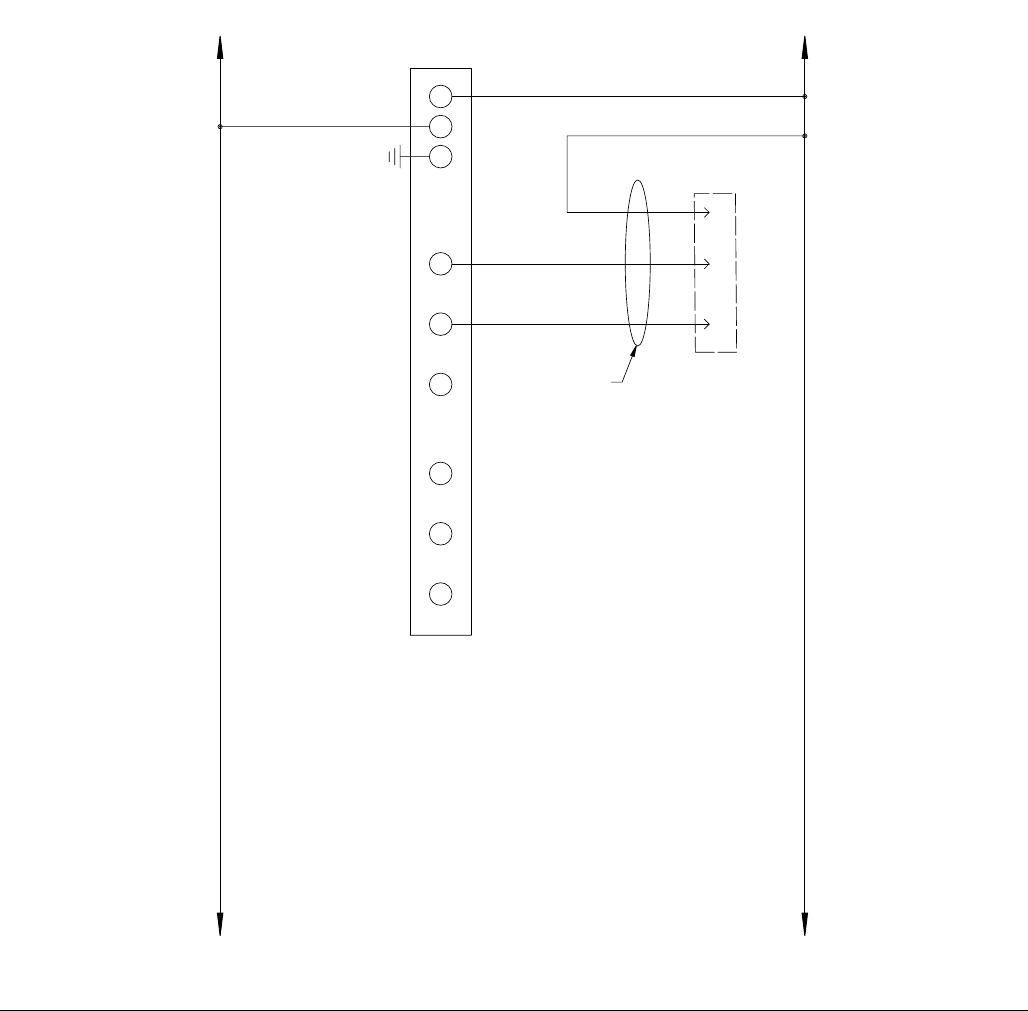
Schematics
3A0260H 73
FIG. 36: Schematics, Page 8 of 10
451
450
461
468
466
463
458
456
454
452
462
469
465
467
464
460
457
455
453
459
474
471
470
473
472
475
V0
24VDC
125
130
24VDC
COM
DC
EXP-2
L+
GND
M
ANALOG OUTPUT
125 130
M0
I0
24
26 PIN MALE
HIGH DENSITY
D-SUB
412
25
410
26
130
HARNESS
124292
DRIVE-1 I/O
ANALOG OUT
+/- 10 VDC
COMMANDED
FLOW TO DRIVE
486
498
496
494
490
492
488
484
482
480
478
476
487
499
497
495
491
493
489
485
483
481
479
477
125 130
V1
M1
I1
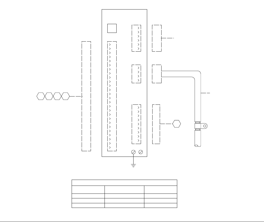
Schematics
74 3A0260H
FIG. 37: Schematics, Page 9 of 10
DRIVE-1
J5 SERIAL
PORT
4
3
2
1
J3
FEEDBACK
5
6
J4
COMMAND I/O
5
4
3
2
1
9
8
7
6
13
12
11
10
17
16
15
14
20
19
18
24
23
22
21
26
25
4
3
2
1
J2
MOTOR
POWER
4
3
2
1
J1
AC
POWER
7
6
5
9
8
516
525
523
521
518
514
512
510
508
506
504
502
500
517
524
520
522
519
515
513
511
509
507
505
503
501
534
541
539
536
532
530
528
526
535
542
538
540
537
533
531
529
527
543
544
102
HARNESS
124292
209
HARNESS
124292
358446
26 PIN MALE
HIGH DENSITY
D-SUB
MOTOR POWER CABLE
SEE CHART
FEEDBACK CABLE
SEE CHART
PE
549
547
545
548
546
474
DRIVE CABLE CHART
CONTROL P/N FEEDBACK CABLE POWER CABLE
24E630 124254 124251
24E633 124255 124252
24E634 124256 124253
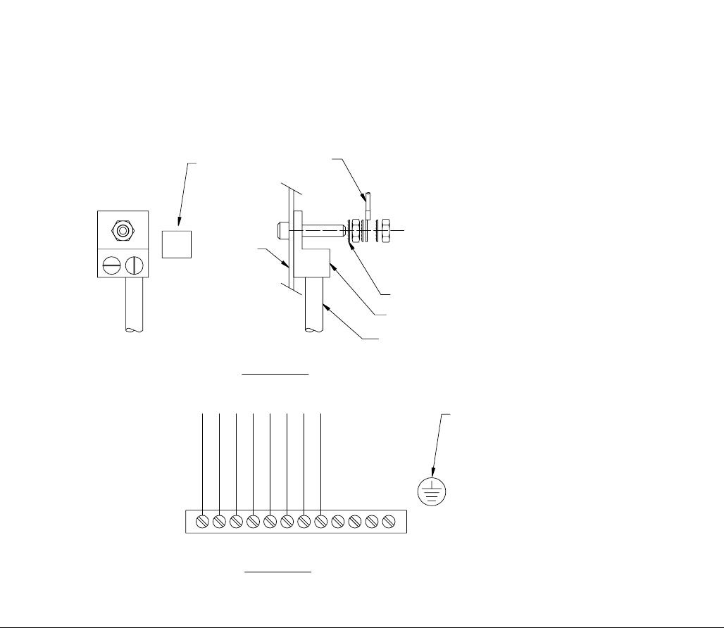
Schematics
3A0260H 75
FIG. 38: Schematics, Page 10 of 10
585
595
593
591
587
555
583
581
579
577
575
573
571
569
567
565
563
559
561
557
553
551
586
594
589
592
588
556
584
582
580
578
576
574
572
570
568
566
564
560
562
558
554
552
550
598
596
599
597
590
GROUND DIST. BAR
FIGURE 2
NTS
PE GROUND STUD GRN/YEL
DRIVE-1 PE
DRIVE-1 J1-1
TERMINAL STRIP
AMP-2
AMP-1
FIGURE 1
NTS
PLACE NEAR
GROUND DIST BAR
GROUNDING NOTES:
1. GROUND ALL DISTRIBUTION BARS F/N
2. GROUND ALL DOORS
3. DO NOT JUMPER GROUND WIRES.
TO GROUND
DIST. BAR #1
STAR WASHER
GROUND LUG
INCOMING GROUND
PROTECTIVE EARTH
SUBPLATE
PE
PLACE NEAR
GROUND LUG
FIL-2
FIL-1
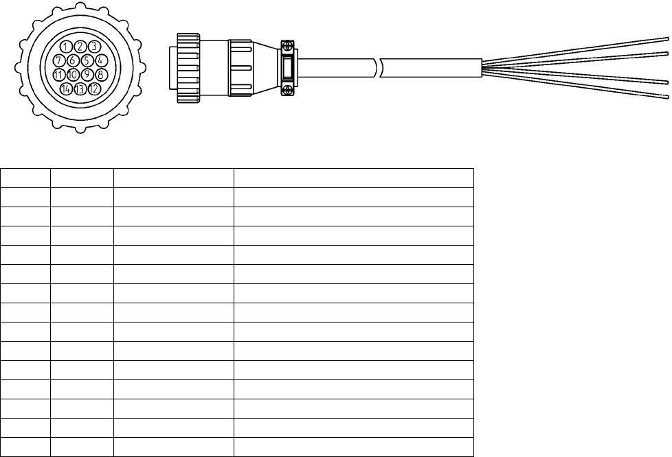
Accessory Parts
76 3A0260H
Accessory Parts
Automation Interface Cable Assembly
The cable length of automation interface cable assembly 24D824 is 40 ft (12.2 m). This figure shows the cable and
identifies the cable interface signals. See Appendix B - I/O on page 95 for wiring details. See Appendix C - Theory
of Operation on page 98.
Pin # Wire # Color Description
1 208 Black Dispense Start
2 210 Red Job Complete
3 SPARE White N/C
4 SPARE White/Black N/C
5 125 Orange 24 VDC from PGM
6 130 Blue 24 VDC common
7 404 Red/Black Analog flow command
8 406 Green Analog common
9 SPARE Green/Black N/C
10 302 Blue/Black Dispenser ready
11 300 Red/White Fault present
12 304 Orange/Black In cycle
13 SPARE Green/White Minimum volume dispensed
14 310 Blue/White 24 VDC thru E-stop
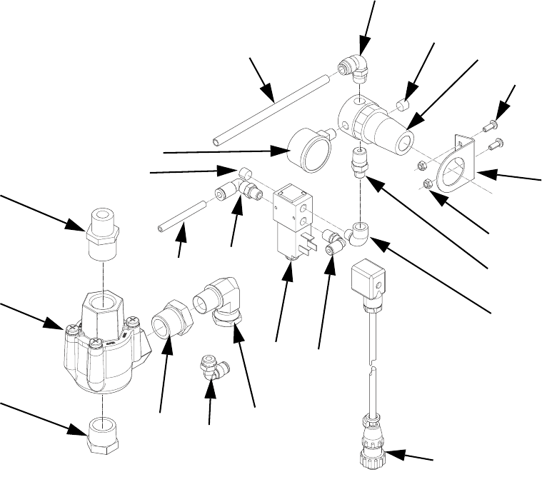
Accessory Parts
3A0260H 77
Dynamic Regulators
1011
1004
1008
1006
1010
1013
1001 1005
1004
1004
1014
1016
1003
1002
1012
1007
1009
1018
1017
1021
1020 1019
Ref Part Description Qty
1001 112699 TUBE, 1/4 OD 2
1002 C20466 FITTING, nipple, hex 1
1003 112307 FITTING, elbow, street 1
1004 100139 PLUG, pipe 2
1005 112781 FITTING, elbow, swivel 1
1006 054776 TUBE, nylon, round, 5/16 in/ 8 mm 2
1007 110321 BRACKET, mounting 1
1008 297612 SCREW, cap, button head 2
1009 110318 REGULATOR, air, 1/4 in. npt 1
1010 110319 GAUGE, pressure, air, 1/8 npt 1
1011 115948 FITTING, elbow, 1/4 nptM, 5/16T OD 1
1012 107110 NUT, lock 2
1013 121022 FITTING, elbow, male, 1/4 npt 1
1014 198171 FITTING, elbow 1
1015 198446 VALVE, dispense, closer 1
1016 24E574 CABLE, feed regulator, PGM, 9 meter 1
1017 080226 VALVE, quick exhaust, 3/4 in. nptf 1
1018 C20461 FITTING, nipple, reducing, hex 1
1019 125466 FITTING, swivel, elbow, 1/2 nptf 1
1020 100896 FITTING, bushing, pipe 1
1021 111530 MUFFLER 1

Accessory Parts
78 3A0260H
Dynamic Regulator Setup and Installation
1. Remove air pressure from Therm-O-Flow supply
system. See Pressure Relief Procedure in manual
311208.
2. Install dynamic regulator kit. See FIG. 39 on
page 79.
3. Apply air to the Therm-O-Flow supply. Check for air
leaks.
4. Set the secondary regulator for a low operating
pressure, for example 20-25 psi.
5. Adjust the panel mount Therm-O-Flow regulator to
zero psi.
6. Connect the dynamic regulator cable from the
Therm-O-Flow to the PGM control box.
7. Navigate to the Supply Pump screen. See Appen-
dix A - User Interface Display starting on page 81
for Supply Pump screen information.
8. Select ON mode for the Primary or Tandem Pump
drop-down menu.
9. Set the appropriate press for the panel mount regu-
lator on the Therm-O-Flow. For example, 30-40 psi.
10. Select AUTO mode for the Primary or Tandem
Pump drop-down menu.
11. Verify operation of the new regulator and adjust
pressure as needed to achieve a maximum static
pressure of 1500 psi (103 bar) when the system is
not dispensing.
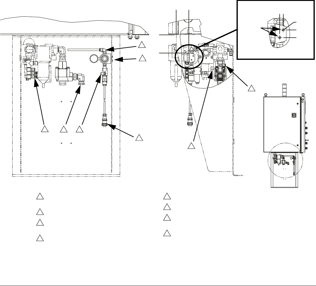
Accessory Parts
3A0260H 79
Dynamic Regulator Installation
The dynamic regulator kit is used to control the static
pressure of a Therm-O-Flow. The PGM has a maximum
inlet pressure of 1500 psi. During dispense the dynamic
regulator kit will activate the normal regulator located on
the front panel of the Therm-O-Flow. When the system
is idle the secondary regulator will control static pres-
sure.
FIG. 39
Detail A
3
1
6
2
4
11/16 in
.
7/32 in.
5
diameter
7
8
Remove plug and attach supplied tubing to
regulator inlet.
Holes required for mounting. See detail A.
5/32 in. tubing removed from Therm-O-Flow
regulator to be attached here.
Regulator pilot port will have an existing 5/32 in.
air line. This air line and its fitting are to be
removed from the regulator and replaced with
the fitting supplied with dynamic regulator.
The existing pilot tube will be connected to the
5/32 fitting on the diverting valve supplied with
24E575.
To Therm-O-Flow regulator pilot port.
Regulator inlet.
Thread existing air line with 1/2 in. npt coupling
to 90° swivel fitting.
Attach to PGM control panel.
1
2
3
4
5
6
7
8
5/16 in.
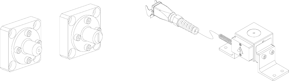
Accessory Parts
80 3A0260H
Endure Valve Nozzles Heater Nests
Part Description
24E654 10 x 1.5 mm Ribbon Nozzle
24E655 1/8 in. Bead Nozzle
Part Description
24E678 Heater Nest with Blank Insert
24E679 Heater Nest with Ported Insert
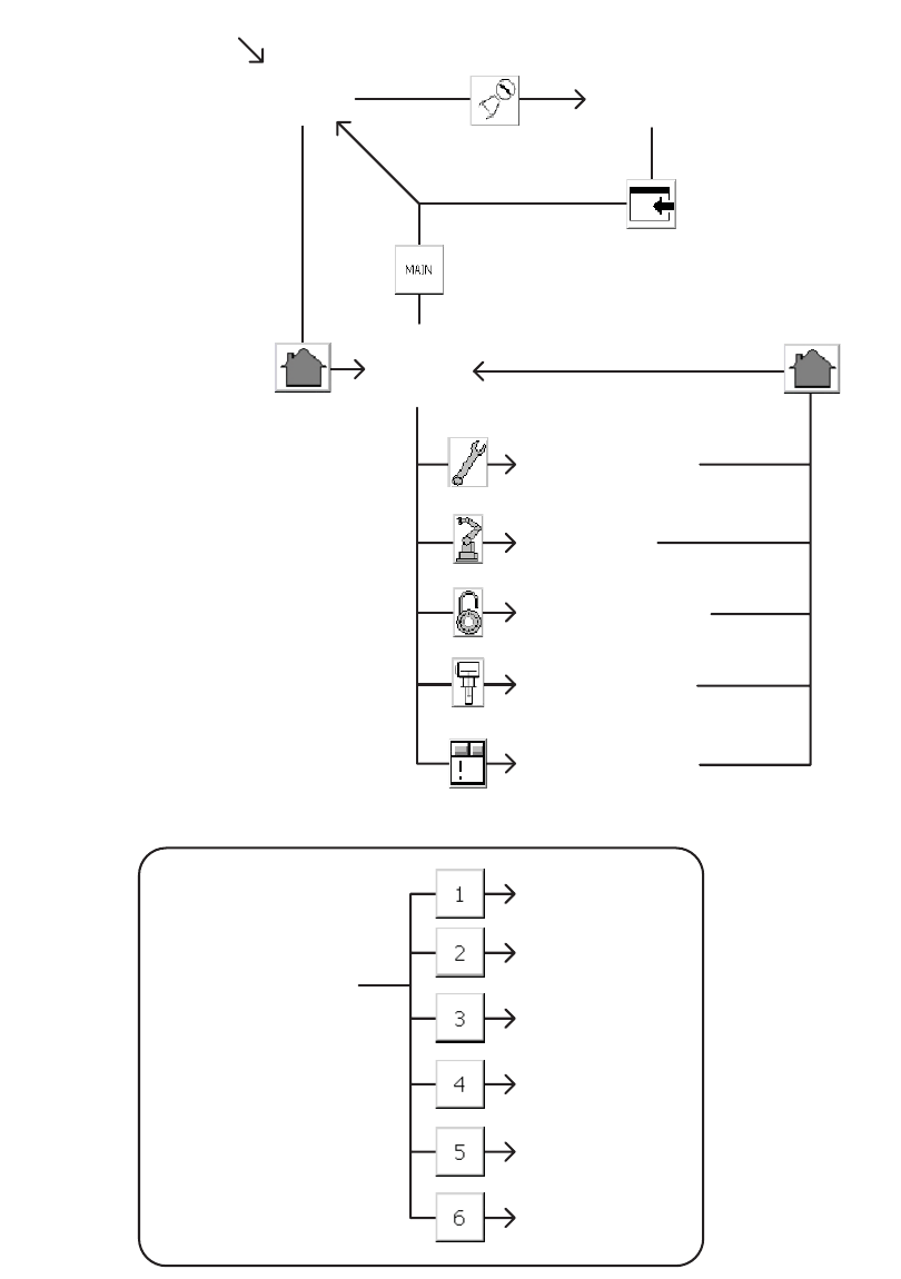
Appendix A - User Interface Display
3A0260H 81
Appendix A - User Interface Display
Screen Navigation Diagram
Screen #1
Current Setup
Screen
Screen #2
Screen #3
Screen #4
Screen #5
Main
START MACHINE
Maintenance
Home
Calibrate
Robot I/O
Setup Screens Flow
Supply Pump
Setup Screens
Alarm Screen
Screen #6
Appendix A - User Interface Display
82 3A0260H
Main Screen
Press the appropriate button to navigate to either the Home or Calibration screen. Enter password “PGM10”to
access the Calibration screen.
Key:
A Navigate to the Home screen
B Navigate to the Calibrate screen
AB
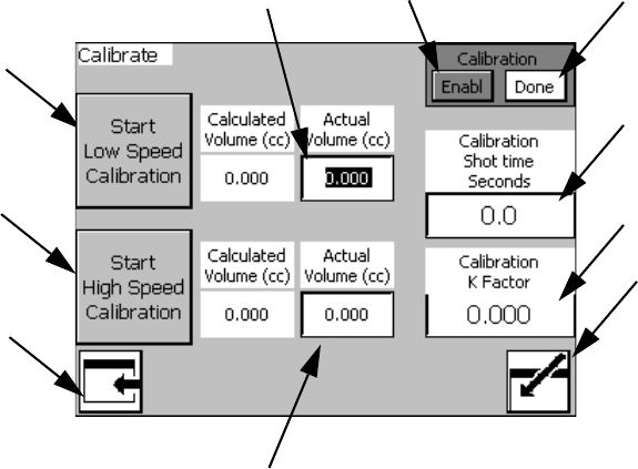
Appendix A - User Interface Display
3A0260H 83
Calibrate Screen #1
NOTE: See Calibration procedure on page 25.
Key:
C Enable Calibration button (Begin
Calibration)
D Done button (Finish Calibration)\
E Calibration Shot Time Input Box
F Calibration K Factor (Automatically
Calculated)
G Start Low Speed Calibration button
H Low Speed Calibration Shot Volume Input
Box
J Start High Speed Calibration button
K High Speed Calibration Shot Volume Input
Box
L Navigate to Main Screen
M Enter Calibration Screen
C
J
L
D
G
H
K
E
F
M
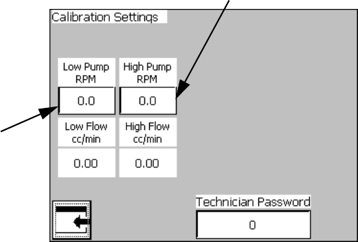
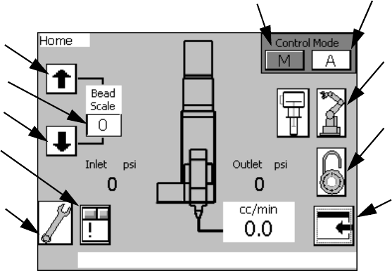
Appendix A - User Interface Display
3A0260H 85
Home Screen
Manual Mode
In Manual Mode, the machine only accepts signals from
the User Interface touch screen and the physical buttons
on the machine. All signals from an External Control
Interface to initiate a shot will be ignored.
Automatic Mode
In Automatic Mode, the machine only accepts initiate
shot signals from an external machine. All signals to ini-
tiate a shot using the User Interface touch screen or the
physical buttons on the machine will be ignored.
Bead Scale
The bead scale function adjusts the quantity dispensed
by the scale percent value shown. For example, if the
system is setup to dispense 100 cc/min and the bead
scale setting is 110 then the machine will dispense
100 cc/min x 110% scale =110 cc/min.
The primary purpose of the bead scale is to be able to
quickly adjust volume dispensed to be able to find that
actual desired volume. Once the correct volume is
found, the flow rate should be adjusted accordingly.
Screens Navigation
Access to the Setup screens requires the Supervisor
password.
Flow Rate Display
The Home screen will display the commanded Flow
Rate from 1 of 3 sources:
• 1 - Maintenance Flow Rate (see Maintenance
Screen on page 86)
• 2 - Auto Mode Display Flow (see Setup #2 Screen
on page 89)
• 3 - Remote 0-10 VDC Command Flow (see Appen-
dix B - I/O on page 95)
Key:
N Enable Manual mode
P Enable Automatic mode
R Increase Bead Scale
S Decrease Bead Scale
T Current Bead Scale setting
U Navigate to Maintenance Screen
V Navigate to Robot I/O Screen
W Navigate to Setup Screens
X Navigate to Main Screen
Y Navigate to Alarm Screen
NP
V
W
X
R
S
T
U
Y
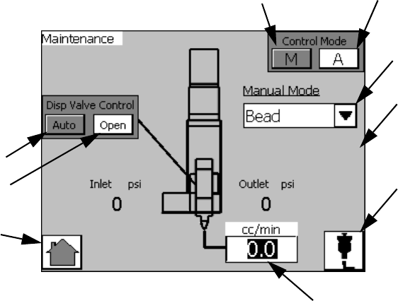
Appendix A - User Interface Display
86 3A0260H
Maintenance Screen
Dispense Valve Control
When Automatic Dispense Valve Control is enabled, the
dispense valve will open and close as needed to dis-
pense material.
When Open the Dispense Valve is selected, the dis-
pense valve will open and remain open until Automatic
Dispense Valve Control is enabled.
Dispense Settings
Dispense Mode: Options include Bead and Shot.
• In Bead mode, dispensing begins when the initiate
shot button is pressed and dispensing ends when
the initiate shot button is released.
• In Shot mode, dispensing begins when the initiate
shot button is pressed and released. Dispensing
ends when the Dispense Duration (AC) elapses.
Dispense Duration: This is the amount of time the
machine will dispense at the given flow rate. This value
is only used in Shot Mode.
Flow Rate: This is the rate at which the machine will
dispense for the given dispense duration.
Manual Start Dispense
After adjusting the settings, the user can press the Man-
ual Start Dispense button (AE) to dispense material
using the current settings.
NOTE: This button performs the same function as the
manual purge button located on the control panel.
Key:
Z Enable Automatic Dispense Valve
Control
AA Open the Dispense Valve, Disable
Automatic Dispense Valve Control
AB Dispense Mode Selection
drop-down menu
AC Dispense Duration Input Box
AD Flow Rate Input Box
AE Manual Start Dispense
AE
AC
Z
AA
AB
AD
NP
A
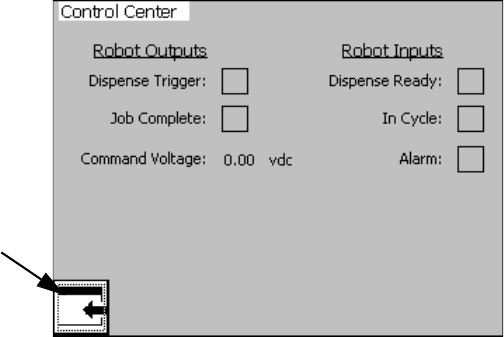
Appendix A - User Interface Display
3A0260H 87
Robot I/O Screen
Overview
This screen is for settings related to an external
machine setup to control the dispense operation of this
system. See Appendix B - I/O on page 95 for more
information.
Robot Outputs
These are signals sent by the external machine when
the related action should occur. The Job Complete sig-
nal is sent to stop the In Cycle signal. The Dispense
Trigger is sent to begin dispensing. The Command Volt-
age is a display of the voltage of the command cable
and is for troubleshooting only. See Appendix B - I/O on
page 95 for more information.
Robot Inputs
These are signals sent to the external machine to notify
it of system conditions. The Dispense Ready signal tells
the external machine that the system is ready to dis-
pense and a dispense can be initiated. The No Alarm
signal tells the machine that there are currently no active
alarms. The In Cycle signal tells the external machine
that the system is currently busy so dispensing cannot
be initiated.
NOTE: Dispense Ready remains on while in Auto Mode.
If a deviation alarm occurs the Dispense Ready and
Alarm signal will remain ON. If an error alarm occurs the
Dispense Ready will be removed.
A
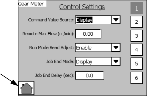
Appendix A - User Interface Display
88 3A0260H
Setup #1 Screen
#1 to #6 Buttons
Press to navigate to the Setup Screen with that number.
For example, press #3 to navigate to Setup Screen #3.
Command Value Source
Command Values can be controlled by the user-inter-
face touch screen or by an external machine connected
to the system via the External Control Interface.
Run Mode Bead Adjust
When this option is enabled the Bead Scale function
appears on the Home Screen. See the Home Screen
on page 85 for more information.
Job End Mode
The In Cycle signal can be dropped when the dispense
trigger is removed when Display is selected.
If Remote is selected the Job Complete signal is
required to remove the In Cycle signal.
Job End Delay (sec)
When Job End mode is set to Display the In Cycle signal
is removed after the time in this field.
A
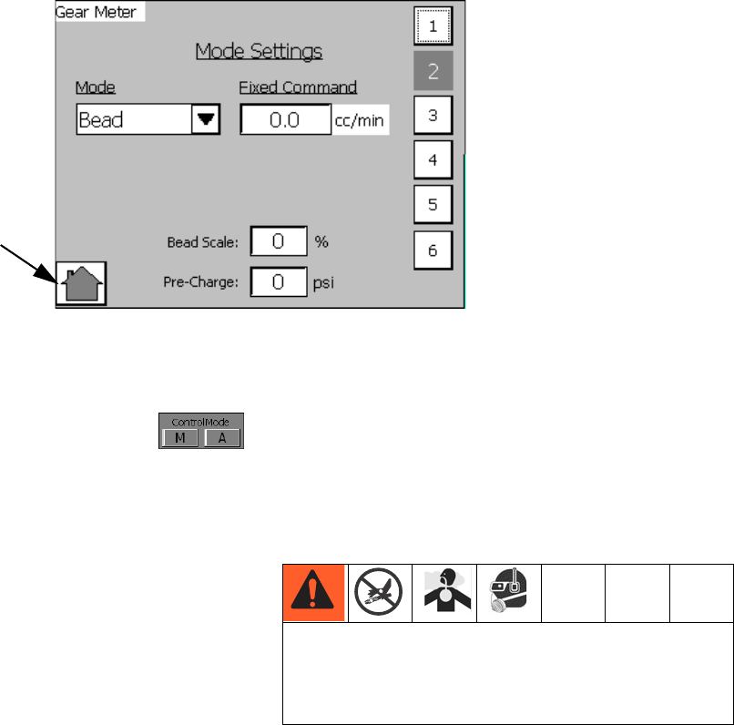
Appendix A - User Interface Display
3A0260H 89
Setup #2 Screen
Overview
The Dispense Mode, Flow Rate, and Dispense Duration
settings apply to Automatic Control Mode (A)
only. Values changed on this screen independent of
changes made on the Maintenance screen.
The Bead Scale value is a duplicate to the Bead Scale
setting on the Home Screen, which can be enabled or
disabled from the Setup #1 screen. See Setup #1
Screen on page 88 for more information.
Fixed Command cc/min
Flow rate can be entered here. This field is only used
when command value source is set to Display on Setup
Screen 1. See Setup #1 Screen on page 88 for more
information.
#1 to #6 Buttons
Press to navigate to the Setup Screen with that number.
For example, press #3 to navigate to Setup Screen #3.
Pre-Charge
This is the pressure between the meter and the dis-
pense valve when the dispense valve is closed. If the
pre-charge setting is non-zero then, immediately after
dispensing, the gear meter will continue to rotate after
the dispense valve closes until the pre-charge pressure
value is achieved. The maximum Pre-Charge value is
2500 psi (17.2 MPa, 172 bar).
A
Larger values for the On Delay setting lead to larger
pressures in the system. If a value too large is input,
the machine could over-pressurize leading to rup-
tured components and serious injury.
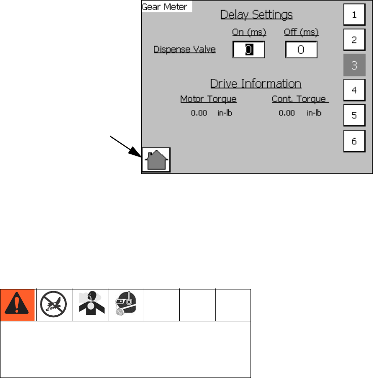
Appendix A - User Interface Display
90 3A0260H
Setup #3 Screen
#1 to #6 Buttons
Press to navigate to the Setup Screen with that number.
For example, press #3 to navigate to Setup Screen #3.
Delay Settings
The Delay Settings affect the timing of the Dispense
Valve opening and closing when a shot is initiated.
The On Delay is the amount of time, in milliseconds,
between a shot being initiated and the dispense valve
opening. If the On Delay is set to 100 the machine will
wait 100 milliseconds after a shot is initiated before
opening the dispense valve. This will lead to a pressure
build up between the meter and dispense valve until the
dispense valve opens.
The Off Delay is the amount of time, in milliseconds,
between a shot completing and the dispense valve clos-
ing. If the Off Delay is set to 100 the machine will wait
100 milliseconds after a shot is complete before closing
the dispense valve.
Drive Information
Motor Torque
Display motor torque during dispense. If motor torque
climbs above continuous torque an alarm is issued. See
Errors on page 33.
Cont. Torque
Continuous torque rating of the motor.
NOTE: The motor torque display is a good way to deter-
mine the maximum flow rate with a given viscosity.
A
Larger values for the On Delay setting lead to larger
pressures in the system. If a value too large is input,
the machine could over-pressurize leading to rup-
tured components and serious injury.
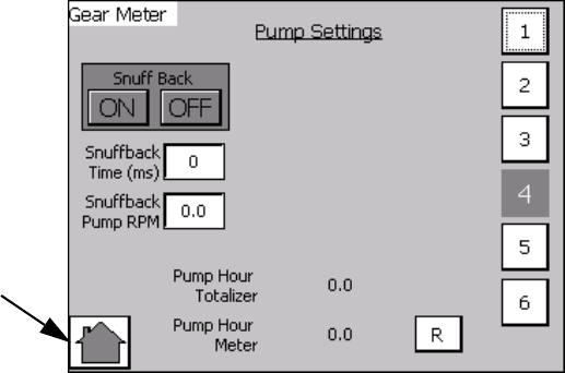
Appendix A - User Interface Display
3A0260H 91
Setup #4 Screen
#1 to #6 Buttons
Press to navigate to the Setup Screen with that number.
For example, press #3 to navigate to Setup Screen #3.
Pump Settings
Snuff Back: This enables the gear meter to rotate in
reverse, immediately following dispensing, to pull mate-
rial back from the dispense valve to minimize or elimi-
nate material drooling. The Snuff Back Time and Snuff
Back Pump RPM are the settings used when Snuff Back
is enabled. These settings should be adjusted to work
best for your material.
NOTE: Not recommended for very viscous materials.
Pump Hour Totalizer: This field will record the total dis-
pense time on the machine in hours. This field is
non-resettable.
Pump Hour Meter: This field displays total dispense
time in hours. This field is resettable.
A
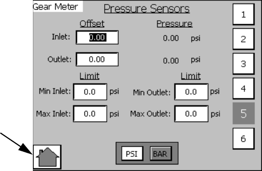
Appendix A - User Interface Display
92 3A0260H
Setup #5 Screen
Overview
This screen controls settings for the pressure sensors.
These values are used for triggering errors.
#1 to #6 Buttons
Press to navigate to the Setup Screen with that number.
For example, press #3 to navigate to Setup Screen #3.
Inlet, Outlet Offset
The inlet, outlet offset values are used to tune the pres-
sure transducer. If the pressure transducers do not reg-
ister zero pressure when there is no material in the
system, enter a value to shift the pressure value to zero.
For example, if 15 psi is shown, enter -15 psi to shift the
value to 0.
Min/Max Inlet/Outlet Limits
These limit values are used to set the acceptable range
of values for dispensing. If values are outside of this
range during dispensing the machine will issue an
alarm. See Errors on page 33.
PSI, BAR
Set the unit of measure for pressure system-wide.
A
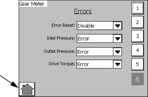
Appendix A - User Interface Display
3A0260H 93
Setup #6 Screen
Errors
Error Reset: If set to Disable, errors cannot be reset. If
set to Enable, errors can be reset.
Inlet/Outlet Pressure, Drive Torque: If set to Error, an
error will be generated when the out-of-limit condition
occurs. The machine will be disabled until the error is
reset. If set to deviation, an error will be generated when
the out-of-limit condition occurs. The machine will not be
disabled until the error is reset.
If set to Deviation, an error will be generated when the
out-of-limit condition occurs. The machine will not be
disabled. See Errors on page 33.
A
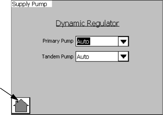
Appendix A - User Interface Display
94 3A0260H
Supply Pump Screen
NOTE: This screen is used to control the optional
dynamic regulator kit for a Therm-O-Flow. See
Accessory Parts section on page 76 for additional
information on the dynamic regulator kit option.
Dynamic Regulator
Primary Pump
•Auto Mode: During normal operation this mode will
activate the dynamic regulator solenoid when the
dispense valve solenoid is activated
•ON Mode: This will activate the dynamic regulator
solenoid
•OFF Mode: The dynamic regulator option is dis-
abled
Tandem Pump
• Same control features as primary pump
A
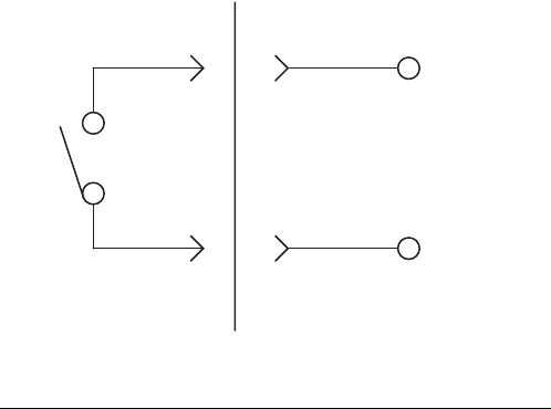
Appendix B - I/O
3A0260H 95
Appendix B - I/O
Using the PGM I/O
The gear meter uses several I/O signals to communicate with plant automation controllers. There are two digital
inputs, three digital outputs, and one analog input. All of these signals are routed to the I/O connector on the top of
the controller.
Other pins on the I/O connector include 24 VDC power, 24 VDC common, analog common, and a signal which is 24
VDC power only when the controller E-Stop switch is latched in. None of the signals are isolated; all are referenced to
the ground plane of the control box. The following paragraphs describe typical connection methods for the automa-
tion controller signals.
Digital Inputs
The two digital inputs are Dispense Start and Job Com-
plete. These inputs require a 24 VDC current sourcing
output from the automation controller. See FIG. 40.
If the automation controller uses relay contacts to acti-
vate I/O signals, the 24 VDC available at the gear meter
I/O connector (pin 5) should be used to drive the inputs.
If the automation controller uses high-side switching of
24 VDC, the automation outputs can be directly con-
nected to the inputs as long as the 24 VDC common
(pin 6) of the gear meter is able to be connected to the
automation controller common. If the automation con-
troller outputs are low-side switching (open collector) or
a voltage other than 24 VDC, relays must be used as
shown in FIG. 40.
FIG. 40
Automation PGM Control
Input Circuit
24VDC
Relay
Contact
Input
Pin 1 or 2
5
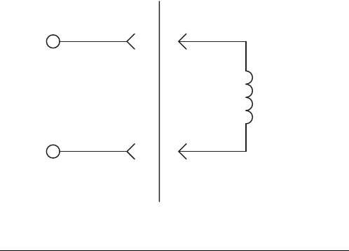
Appendix B - I/O
96 3A0260H
Digital Outputs
The three digital outputs are Dispenser Ready, Fault
Present and In Cycle. These outputs perform high-side
switching of 24 VDC and require a 24 VDC current sink-
ing input at the automation controller. See FIG. 41. If the
automation controller uses 24 VDC relay coils to receive
I/O signals, the signals should be connected as shown
in FIG. 41.
If the automation controller inputs are current sourcing
or use a voltage other than 24 VDC, relays with 24 VDC
coils must be used as shown in FIG. 41.
FIG. 41
AutomationPGM Control
Output Circuit
Load
(750 mA max)
Pins 10, 11, 12
DC Common
6
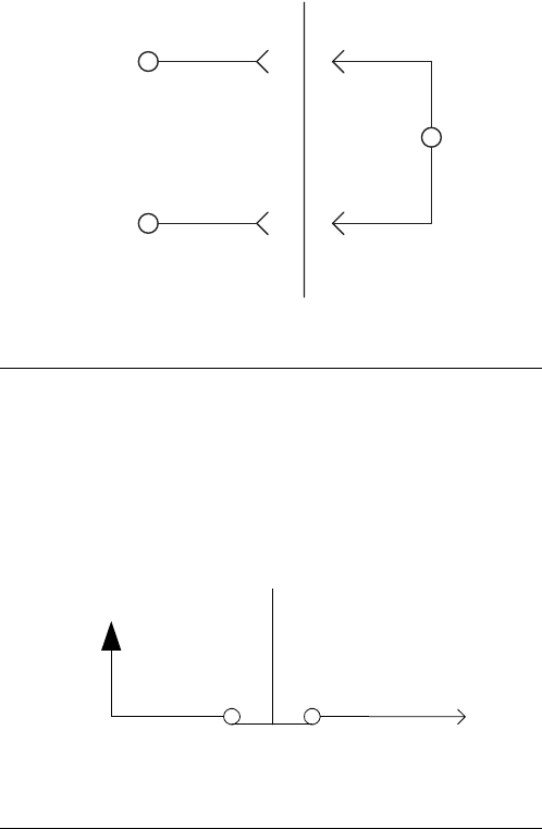
Appendix B - I/O
3A0260H 97
Analog Inputs
The PGM receives a flow rate analog command from
the automation. The 0 to 10 VDC analog input is refer-
enced to analog common on the control. See FIG. 42.
The reference for the automation controller analog out-
put must be connected to the PGM analog reference
(pin 8) for this signal to function properly.
24 VDC From E-Stop
The PGM provides a signal that can be used by the
automation controller to monitor the emergency stop
switch position of the PGM controller. See FIG. 43.
Relays
If the use of relays is required to condition the digital I/O
signals, these are some examples of part numbers that
could be used.
For 24 VDC Coils:
•Relay: Phoenix Contact Part Number: 2966171
For 120 VAC Coils:
•Relay: Phoenix Contact Part Number: 2966197
FIG. 42
FIG. 43
AutomationPGM Control
Analog Input
0 to 10 VDC
Voltage
Pin 8
Pin 7
+
-
_
+24 VDC
E-Stop Switch
Pin 14
Appendix C - Theory of Operation
98 3A0260H
Appendix C - Theory of Operation
Theory of Operation
Input and Output Signals
Terminology
For the purpose of this document a digital signal is said
to be SET when voltage is present (or above the mini-
mum threshold). A signal is said to be RESET when the
signal voltage is not present (below minimum threshold).
Devices are referred to as SET when they are in their
energized or active state.
Digital Inputs
Dispense Start - This is the Dispense Signal. The PGM
unit will attempt to dispense at either the commanded
flowrate while this signal is SET, dependent on mode.
Control On - This input is reset when the E-stop button
is pressed.
Job Complete - This input can be used to signal a job
end.
NOTE: The dispenser ready signal is an important sig-
nal for the automation to monitor. When the dispenser
ready output is not on, the LT may not be responding to
requests from the automation. This could create the sit-
uation where the automation is running production, but
the PGM is not dispensing any material.
Dispense Valve Solenoid - This signal will be set to
energize the dispense valve solenoid at the beginning of
a dispense cycle.
Fault Present - This bit is RESET under the following
conditions:
1. No Faults (alarms or warnings) are active.
In Cycle - In Cycle signal is set at the beginning of a dis-
pense cycle. It is reset at the end of the dispense cycle.
The dispense cycle can end in two ways, depending on
how the Job End mode is set:
•If the Job End mode is set to remote, dispense cycle
ends when the job complete signal is received from
the automation I/O.
•If the Job End mode is set to Display, dispense cycle
ends when the Job End delay timer expires. See
Appendix A - User Interface Display on page 81.
Analog Input
Flow Command - The flow command signal input rep-
resents flow requests. The voltage must be between 0
and 10 volts DC. The 0-10 volt signal is interpreted as a
relative 0-100% flow command signal. The system must
be in Remote Mode for this input to be used.
See the Accessory Parts on page 76.
Technical Data
3A0260H 99
Technical Data
* Flow rates and viscosities are general estimates. Flow rates drop as viscosity increases. Fluids are expected to
shear under pressure. New applications or fluids should always be tested to determine proper line sizes and
equipment selections. See your Graco Authorized distributor for other capabilities.
Volume repeatability . . . . . . . . . . . . . . . . . . . . . . . . . . . +/- 1%
Minimum Flow Rate . . . . . . . . . . . . . . . . . . . . . . . . . . . . 6 cc/rev model: 30 cc/min
20 cc/rev model: 40 cc/min
Maximum Flow Rate . . . . . . . . . . . . . . . . . . . . . . . . . . . 6 cc/rev model: 480 cc/min
20 cc/rev model: 1600 cc/min
Minimum Dispensed Shot Size . . . . . . . . . . . . . . . . . . . 6 cc/rev model: 8 cc
20 cc/rev model: 10 cc
Maximum Fluid Working Inlet Pressure . . . . . . . . . . . . . 1500 psi (10.3 MPa, 103 bar)
Maximum Fluid Working Outlet Pressure . . . . . . . . . . . 2500 psi (17.2 MPa, 172 bar)
Air Supply Pressure Range . . . . . . . . . . . . . . . . . . . . . . 60-100 psi (filtration required)
Fluid Filtration Recommended. . . . . . . . . . . . . . . . . . . . Up to 200 mesh, depending on viscosity
Viscosity Range of Fluids . . . . . . . . . . . . . . . . . . . . . . . 1,000-1,000,000 Centipoise
Wetted Parts . . . . . . . . . . . . . . . . . . . . . . . . . . . . . . . . . Stainless Steel, Tool Steel, Chrome, Carbide, Acetal
Plastic, PTFE, Chemical Resistant O-Rings
Power Requirements . . . . . . . . . . . . . . . . . . . . . . . . . . . Full Load: 18.5A, Fuse Rating: 21A
Power Supply Voltage Range . . . . . . . . . . . . . . . . . . . . 240VAC, 50-60 Hz, single phase
Sound Pressure Level at Maximum Flow Rate . . . . . . . 6 cc/rev model: 58 dB(A)
20 cc/rev model: 72 dB(A)
Sound Power Level at Maximum Flow Rate . . . . . . . . . 6 cc/rev model: 68 dB(A)
20 cc/rev model: 79 dB(A)
Operating Temperature Range . . . . . . . . . . . . . . . . . . . Control: 40-104°F (4-40°C)
Heated Pump: 40-400°F (4-204°C)
Ambient Pump: 40-120°F (4-49°C)
Operating Humidity Range . . . . . . . . . . . . . . . . . . . . . . 10-90% non-condensing
Weight . . . . . . . . . . . . . . . . . . . . . . . . . . . . . . . . . . . . . . 6 cc/rev model: 30 lb (13.61 kg)
20 cc/rev model: 60 lb (27.22 kg)
Controls: 100 lb (45.36 kg)
Overall Dimensions . . . . . . . . . . . . . . . . . . . . . . . . . . . . 6 cc/rev model: 19.75 H x 9.38 W x 6.6 D in.
(50.17 H x 23.83 W x 16.76 D mm)
20 cc/rev model: 21.75 H x 9.5 W x 8.9 D in.
(55.25 H x 24.13 W x 22.6 D mm)
Control: 30 H x 24 W x 12D in.
(76.2 H x 60.96 W x 30.48 D mm)
All written and visual data contained in this document reflects the latest product information available at the time of publication.
Graco reserves the right to make changes at any time without notice.
For patent information, see www.graco.com/patents.
Original instructions. This manual contains English. MM 3A0260
Graco Headquarters: Minneapolis
International Offices: Belgium, China, Japan, Korea
GRACO INC. AND SUBSIDIARIES • P.O. BOX 1441 • MINNEAPOLIS MN 55440-1441 • USA
Copyright 2010, Graco Inc. All Graco manufacturing locations are registered to ISO 9001.
www.graco.com
Revised September 2013
Graco Standard Warranty
Graco warrants all equipment referenced in this document which is manufactured by Graco and bearing its name to be free from defects in
material and workmanship on the date of sale to the original purchaser for use. With the exception of any special, extended, or limited warranty
published by Graco, Graco will, for a period of twelve months from the date of sale, repair or replace any part of the equipment determined by
Graco to be defective. This warranty applies only when the equipment is installed, operated and maintained in accordance with Graco’s written
recommendations.
This warranty does not cover, and Graco shall not be liable for general wear and tear, or any malfunction, damage or wear caused by faulty
installation, misapplication, abrasion, corrosion, inadequate or improper maintenance, negligence, accident, tampering, or substitution of
non-Graco component parts. Nor shall Graco be liable for malfunction, damage or wear caused by the incompatibility of Graco equipment with
structures, accessories, equipment or materials not supplied by Graco, or the improper design, manufacture, installation, operation or
maintenance of structures, accessories, equipment or materials not supplied by Graco.
This warranty is conditioned upon the prepaid return of the equipment claimed to be defective to an authorized Graco distributor for verification of
the claimed defect. If the claimed defect is verified, Graco will repair or replace free of charge any defective parts. The equipment will be returned
to the original purchaser transportation prepaid. If inspection of the equipment does not disclose any defect in material or workmanship, repairs will
be made at a reasonable charge, which charges may include the costs of parts, labor, and transportation.
THIS WARRANTY IS EXCLUSIVE, AND IS IN LIEU OF ANY OTHER WARRANTIES, EXPRESS OR IMPLIED, INCLUDING BUT NOT LIMITED
TO WARRANTY OF MERCHANTABILITY OR WARRANTY OF FITNESS FOR A PARTICULAR PURPOSE.
Graco’s sole obligation and buyer’s sole remedy for any breach of warranty shall be as set forth above. The buyer agrees that no other remedy
(including, but not limited to, incidental or consequential damages for lost profits, lost sales, injury to person or property, or any other incidental or
consequential loss) shall be available. Any action for breach of warranty must be brought within two (2) years of the date of sale.
GRACO MAKES NO WARRANTY, AND DISCLAIMS ALL IMPLIED WARRANTIES OF MERCHANTABILITY AND FITNESS FOR A
PARTICULAR PURPOSE, IN CONNECTION WITH ACCESSORIES, EQUIPMENT, MATERIALS OR COMPONENTS SOLD BUT NOT
MANUFACTURED BY GRACO. These items sold, but not manufactured by Graco (such as electric motors, switches, hose, etc.), are subject to
the warranty, if any, of their manufacturer. Graco will provide purchaser with reasonable assistance in making any claim for breach of these
warranties.
In no event will Graco be liable for indirect, incidental, special or consequential damages resulting from Graco supplying equipment hereunder, or
the furnishing, performance, or use of any products or other goods sold hereto, whether due to a breach of contract, breach of warranty, the
negligence of Graco, or otherwise.
FOR GRACO CANADA CUSTOMERS
The Parties acknowledge that they have required that the present document, as well as all documents, notices and legal proceedings entered into,
given or instituted pursuant hereto or relating directly or indirectly hereto, be drawn up in English. Les parties reconnaissent avoir convenu que la
rédaction du présente document sera en Anglais, ainsi que tous documents, avis et procédures judiciaires exécutés, donnés ou intentés, à la suite
de ou en rapport, directement ou indirectement, avec les procédures concernées.
Graco Information
For the latest information about Graco products, visit www.graco.com.
TO PLACE AN ORDER, contact your Graco distributor or call to identify the nearest distributor.
Phone: 612-623-6921 or Toll Free: 1-800-328-0211 Fax: 612-378-3505
