Graco 3A2175A Hfrl And Hfrs Setup Users Manual HFRS, Operation, English
2015-04-02
: Graco Graco-3A2175A-Hfrl-And-Hfrs-Setup-Users-Manual-685882 graco-3a2175a-hfrl-and-hfrs-setup-users-manual-685882 graco pdf
Open the PDF directly: View PDF ![]() .
.
Page Count: 96
- Related Manuals
- Models
- Warnings
- Important Two-Component Material Information
- A (Red) and B (Blue) Components
- Typical HFRS System
- Typical HFRL System
- Component Identification
- Dispense Valve Overview
- Setup
- Operation
- Maintenance
- Troubleshooting
- Advanced Display Module (ADM) Operation
- Appendix A - ADM Icons Overview
- Appendix B - ADM Setup Screens Overview
- Appendix C - ADM Run Screens Overview
- Appendix D - ADM Error Codes
- Appendix E - System Events
- Appendix F - USB Operation
- Accessories
- Technical Data
- Graco Standard Warranty
- Graco Information
3A2175A
EN
Setup - Operation
HFRL and HFRS
Hydraulic, Plural-Component, Fixed-Ratio Proportioner.
For pouring and dispensing laminates and silicones.
For professional use only. Not approved for use in explosive atmospheres or hazardous
locations.
See page 4 for model information and maximum
working pressure.
Patent Pending
Important Safety Instructions
Read all warnings and instructions in this
manual. Save these instructions.
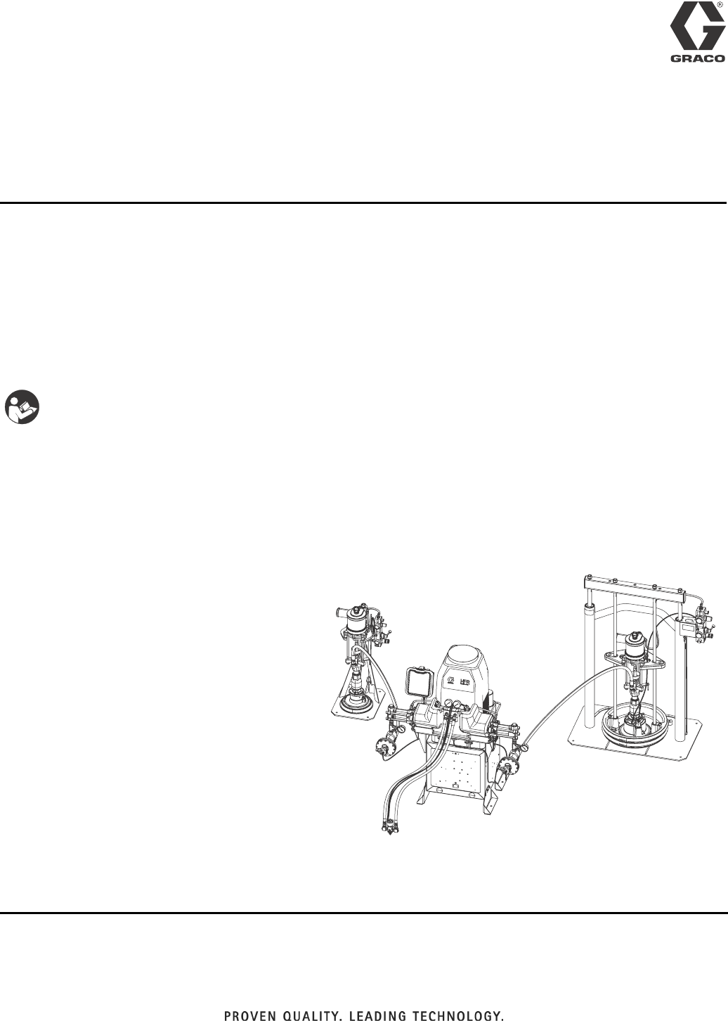
ti18208a
Silicone unit shown.
23A2175A
Contents
Related Manuals . . . . . . . . . . . . . . . . . . . . . . . . . . . 3
Models . . . . . . . . . . . . . . . . . . . . . . . . . . . . . . . . . . . 4
HFR-Laminate (HFRL) . . . . . . . . . . . . . . . . . . . . 4
HFR-Silicone (HFRS) . . . . . . . . . . . . . . . . . . . . . 6
Warnings . . . . . . . . . . . . . . . . . . . . . . . . . . . . . . . . 10
Important Two-Component Material Information 14
Isocyanate Conditions . . . . . . . . . . . . . . . . . . . . 14
Material Self-ignition . . . . . . . . . . . . . . . . . . . . . 14
Keep Components A (Red) and B (Blue) Separate
14
Moisture Sensitivity of Isocyanates . . . . . . . . . . 14
Changing Materials . . . . . . . . . . . . . . . . . . . . . . 15
A (Red) and B (Blue) Components . . . . . . . . . . . . 15
Typical HFRS System . . . . . . . . . . . . . . . . . . . . . . 16
Typical HFRL System . . . . . . . . . . . . . . . . . . . . . . 17
Component Identification . . . . . . . . . . . . . . . . . . . 18
Hydraulic Power Pack . . . . . . . . . . . . . . . . . . . . 21
Motor Control Module (MCM) . . . . . . . . . . . . . . 22
Advanced Display Module (ADM) . . . . . . . . . . . 24
Fluid Control Module (FCM) . . . . . . . . . . . . . . . 27
Dispense Valve Overview . . . . . . . . . . . . . . . . . . . 28
Setup . . . . . . . . . . . . . . . . . . . . . . . . . . . . . . . . . . . . 29
Operation . . . . . . . . . . . . . . . . . . . . . . . . . . . . . . . . 35
Startup . . . . . . . . . . . . . . . . . . . . . . . . . . . . . . . 35
Shutdown . . . . . . . . . . . . . . . . . . . . . . . . . . . . . 38
Pressure Relief Procedure . . . . . . . . . . . . . . . . 38
Flushing . . . . . . . . . . . . . . . . . . . . . . . . . . . . . . 39
Adjusting Material Inlet Pressure Using the Material
Regulator . . . . . . . . . . . . . . . . . . . . . . . . . . 40
Pressure Balancing Using the Orifice Valve
Assemblies . . . . . . . . . . . . . . . . . . . . . . . . . 41
Maintenance . . . . . . . . . . . . . . . . . . . . . . . . . . . . . . 43
Advanced Display Module (ADM) . . . . . . . . . . . 44
Motor Control Module (MCM) . . . . . . . . . . . . . . 45
Fluid Control Module (FCM) . . . . . . . . . . . . . . . 46
Fluid Inlet Strainer Screen . . . . . . . . . . . . . . . . . 46
IsoGuard Select™ System . . . . . . . . . . . . . . . . 47
Clean Orifice Valves . . . . . . . . . . . . . . . . . . . . . 48
Troubleshooting . . . . . . . . . . . . . . . . . . . . . . . . . . . 49
Light Tower (Optional) . . . . . . . . . . . . . . . . . . . . 49
Common Problems . . . . . . . . . . . . . . . . . . . . . . 49
ADM Troubleshooting . . . . . . . . . . . . . . . . . . . . 51
Motor Control Module . . . . . . . . . . . . . . . . . . . . 52
Fluid Control Module . . . . . . . . . . . . . . . . . . . . . 54
Advanced Display Module (ADM) Operation . . . . 55
Appendix A - ADM Icons Overview . . . . . . . . . . . 56
Appendix B - ADM Setup Screens Overview . . . . 58
Appendix C - ADM Run Screens Overview . . . . . 68
Appendix D - ADM Error Codes . . . . . . . . . . . . . . 74
Appendix E - System Events . . . . . . . . . . . . . . . . 84
Appendix F - USB Operation . . . . . . . . . . . . . . . . . 85
Overview . . . . . . . . . . . . . . . . . . . . . . . . . . . . . . 85
USB Options . . . . . . . . . . . . . . . . . . . . . . . . . . . 85
Download Log Files . . . . . . . . . . . . . . . . . . . . . . 85
Log Files, Folder Structure . . . . . . . . . . . . . . . . 86
Transfer System Settings . . . . . . . . . . . . . . . . . . 88
Update Custom Language . . . . . . . . . . . . . . . . . 89
Accessories . . . . . . . . . . . . . . . . . . . . . . . . . . . . . . 91
Technical Data . . . . . . . . . . . . . . . . . . . . . . . . . . . . 92
Motor Control Module Technical Data . . . . . . . . 93
Dimensions . . . . . . . . . . . . . . . . . . . . . . . . . . . . 94
Graco Standard Warranty . . . . . . . . . . . . . . . . . . . 96
Graco Information . . . . . . . . . . . . . . . . . . . . . . . . . 96

Related Manuals
3A2175A 3
Related Manuals
Manuals are available at www.graco.com.
Component manuals listed below are in English:
System Manuals
3A2176 HFRL and HFRS Repair-Parts
Pumpline Manuals
3A0019 Z-Series Chemical Pumps Instructions-Parts
3A0020 HFR Hydraulic Actuator Instructions-Parts
Feed System Manuals for HFRL Systems
3A0235 Feed Supply Kits Instructions-Parts
Dispense Valve Manuals
312185 MD2 Valve, Instructions-Parts
Accessory Manuals
3A1149 HFR Discrete Gateway Module Kits Manual
Models
43A2175A
Models
HFR-Laminate (HFRL)
HFRL models are designed for use with low viscosity, unheated urethane laminating adhesives at flow rates of up to
30 cc/sec (4 lb/min).
* Full load amps with all devices operating at maximum capabilities. Fuse requirements at various flow rates and
mix chamber sizes may be less.
** Cycle rate should be between 8 and 20 cycles per minute. Max flow rate is determined for continuous service at
120°F (39°C) at stated cpm and pressure. Higher cycle rates are possible at lower temperatures/pressures and
intermittant use. Lower cycle rates are possible, but should be tested under application conditions.
†Dispense rate in excess of max flow and pressure may result in a machine shutdown due to elevated temperature
of the hydraulic system, resulting in a thermal shutdown (T4H1).
★ approved.
‡The maximum fluid working pressure for the base machine without hoses is 3000 psi (20.7 MPa, 207 bar). If
hoses rated at less than 3000 psi are installed, the system maximum fluid working pressure becomes the rating of
the hoses. If 2000 psi hoses were purchased and installed by Graco, the working pressure for the machine is
already setup for the lower 2000 psi (13.8 MPa, 138 bar) working pressure by Graco. If the machine was pur-
chased without hoses and aftermarket hoses rated at or above 3000 psi are to be installed, see instruction man-
ual 3A1276 for the procedure to setup the machine for higher rated hoses. The change in working pressure is
made by changing a rotary switch setting in the Motor Control Module. The minimum pressure rating for hoses is
2000 psi. Do not install hoses with a pressure rating lower than 2000 psi.
Full Load Peak
Amps Per Phase*
Voltage
(phase) System Watts
Maximum Fluid Working
Pressure ‡
psi (MPa, bar)
55 A 230V (1) 12,650 3000
(20.7, 207)
55 A ★400V (3)
A Pump
Size
B Pump
Size cc/stroke
Required cpm@
Flow**
Max Flow †
cc/sec (lb/min)
Max Dispense Pressure
psi (MPa, bar)** Ratio
160 86 246 8
30 (4)
1500 (10, 103)
1.86
100 86 186 10 1.16
86 80 166 11 1.08
80 80 160 12 1.00
80 65 145 13 1.23
80 60 140 13 1.33
80 50 130 14 1.60
86 40 126 15 2.15
60 50 110 17 1.20
65 40 105 18 1.63
60 40 100 19 1.50
60 25 85 20 28 (3.7) 2.40
50 30 80 20 26 (3.5) 1.67
50 25 75 20 25 (3.3) 2.00
50 20 70 20 23 (3.1) 2.50
Models
3A2175A 5
HFRL Models
★ approved.
Part Num-
ber Description
HFRL01 HFR for Lamination, 230/1, 1.00:1,
80/80, Carbon Steel
HFRL02 HFR for Lamination, 230/1, 1.08:1,
86/80, Carbon Steel
HFRL03 HFR for Lamination, 230/1, 1.16:1,
100/86, Carbon Steel
HFRL04 HFR for Lamination, 230/1, 1.20:1,
60/50, Carbon Steel
HFRL05 HFR for Lamination, 230/1, 1.23:1,
80/65, Carbon Steel
HFRL06 HFR for Lamination, 230/1, 1.33:1,
80/60, Carbon Steel
HFRL07 HFR for Lamination, 230/1, 1.50:1,
60/40, Carbon Steel
HFRL08 HFR for Lamination, 230/1, 1.60:1,
80/50, Carbon Steel
HFRL09 HFR for Lamination, 230/1, 1.63:1,
65/40, Carbon Steel
HFRL10 HFR for Lamination, 230/1, 1.67:1,
50/30, Carbon Steel
HFRL11 HFR for Lamination, 230/1, 1.86:1,
160/86, Carbon Steel
HFRL12 HFR for Lamination, 230/1, 2.00:1,
50/25, Carbon Steel
HFRL13 HFR for Lamination, 230/1, 2.15:1,
86/40, Carbon Steel
HFRL14 HFR for Lamination, 230/1, 2.40:1,
60/25, Carbon Steel
HFRL15 HFR for Lamination, 230/1, 2.5:1,
50/20, Carbon Steel
HFRL16 ★HFR for Lamination, 400/3, 1.00:1,
80/80, Carbon Steel
HFRL17 ★HFR for Lamination, 400/3, 1.08:1,
86/80, Carbon Steel
HFRL18 ★HFR for Lamination, 400/3, 1.16:1,
100/86, Carbon Steel
HFRL19 ★HFR for Lamination, 400/3, 1.20:1,
60/50, Carbon Steel
HFRL20 ★HFR for Lamination, 400/3, 1.23:1,
80/65, Carbon Steel
HFRL21 ★HFR for Lamination, 400/3, 1.33:1,
80/60, Carbon Steel
HFRL22 ★HFR for Lamination, 400/3, 1.50:1,
60/40, Carbon Steel
HFRL23 ★HFR for Lamination, 400/3, 1.60:1,
80/50, Carbon Steel
HFRL24 ★HFR for Lamination, 400/3, 1.63:1,
65/40, Carbon Steel
HFRL25 ★HFR for Lamination, 400/3, 1.67:1,
50/30, Carbon Steel
HFRL26 ★HFR for Lamination, 400/3, 1.86:1,
160/86, Carbon Steel
HFRL27 ★HFR for Lamination, 400/3, 2.00:1,
50/25, Carbon Steel
HFRL28 ★HFR for Lamination, 400/3, 2.15:1,
86/40, Carbon Steel
HFRL29 ★HFR for Lamination, 400/3, 2.40:1,
60/25, Carbon Steel
HFRL30 ★HFR for Lamination, 400/3, 2.5:1,
50/20, Carbon Steel
Part Num-
ber Description
Models
63A2175A
HFR-Silicone (HFRS)
HFRS models are designed for use with high viscosity, unheated silicone adhesives at flow rates of up to 20 cc/sec.
The equipment can be ran at up to 20 cycles per minute continuous duty.
* Full load amps with all devices operating at maximum capabilities. Fuse requirements at various flow rates and
mix chamber sizes may be less.
** Cycle rate should be between 8 and 20 cycles per minute. Max flow rate is determined for continuous service at
120°F (39°C) at stated cpm and pressure. Higher cycle rates are possible at lower temperatures/pressures and
intermittent use. Lower cycle rates are possible, but should be tested under application conditions.
†Dispense rate in excess of max flow and pressure may result in a machine shutdown due to elevated temperature
of the hydraulic system, resulting in a thermal shutdown (T4H1).
★ approved.
‡The maximum fluid working pressure for the base machine without hoses is 3000 psi (20.7 MPa, 207 bar). If
hoses rated at less than 3000 psi are installed, the system maximum fluid working pressure becomes the rating of
the hoses. If 2000 psi hoses were purchased and installed by Graco, the working pressure for the machine is
already setup for the lower 2000 psi (13.8 MPa, 138 bar) working pressure by Graco. If the machine was pur-
chased without hoses and aftermarket hoses rated at or above 3000 psi are to be installed, see instruction man-
ual 3A1276 for the procedure to setup the machine for higher rated hoses. The change in working pressure is
made by changing a rotary switch setting in the Motor Control Module. The minimum pressure rating for hoses is
2000 psi. Do not install hoses with a pressure rating lower than 2000 psi.
Full Load Peak
Amps Per Phase*
Voltage
(phase) System Watts
Maximum Fluid Working
Pressure ‡
psi (MPa, bar)
55 A 230V (1) 12,650 3000
(20.7, 207)
55 A ★400V (3)
A Pump
Size
B Pump
Size cc/stroke
Required cpm@
Flow**
Max Flow †
cc/sec
Max Dispense Pressure
psi (MPa, bar)** Ratio
15 80 95 11.3-12.5 18-20
2500 (17, 172)
5.33
5 50 55 20 18.3 10.00
5 30 35 20 11.7 6.00
5 20 25 20 8.3 4.00
10 10 20 20 6.7 1.00
5 10 15 20 5 2.00

Models
3A2175A 7
HFRS Models
Part Num-
ber Description
HFRS01 HFR for Silicone, 230/1, 1:1, Carbon
Steel, 55/55 Feed
HFRS02 HFR for Silicone, 230/1, 1:1, Carbon
Steel, 5/5 Feed
HFRS03 ★HFR for Silicone, 400/3, 1:1, Carbon
Steel, 55/55 Feed
HFRS04 ★HFR for Silicone, 400/3, 1:1, Carbon
Steel, 5/5 Feed
HFRS05 HFR for Silicone, 230/1, 1:1, Stainless
Steel, 55/55 Feed
HFRS06 HFR for Silicone, 230/1, 1:1, Stainless
Steel, 5/5 Feed
HFRS07 ★HFR for Silicone, 400/3, 1:1, Stainless
Steel, 55/55 Feed
HFRS08 ★HFR for Silicone, 400/3, 1:1, Stainless
Steel, 5/5 Feed
HFRS09 HFR for Silicone, 230/1, 4:1, Carbon
Steel, 55/55 Feed
HFRS10 HFR for Silicone, 230/1, 4:1, Carbon
Steel, 55/5 Feed
HFRS11 HFR for Silicone, 230/1, 4:1, Carbon
Steel, 5/5 Feed
HFRS12 ★HFR for Silicone, 400/3, 4:1, Carbon
Steel, 55/55 Feed
HFRS13 ★HFR for Silicone, 400/3, 4:1, Carbon
Steel, 55/5 Feed
HFRS14 ★HFR for Silicone, 400/3, 4:1, Carbon
Steel, 5/5 Feed
HFRS15 HFR for Silicone, 230/1, 4:1, Stainless
Steel, 55/55 Feed
HFRS16 HFR for Silicone, 230/1, 4:1, Stainless
Steel, 55/5 Feed
HFRS17 HFR for Silicone, 230/1, 4:1, Stainless
Steel, 5/5 Feed
HFRS18 ★HFR for Silicone, 400/3, 4:1, Stainless
Steel, 55/55 Feed
HFRS19 ★HFR for Silicone, 400/3, 4:1, Stainless
Steel, 55/5 Feed
HFRS20 ★HFR for Silicone, 400/3, 4:1, Stainless
Steel, 5/5 Feed
HFRS21 HFR for Silicone, 230/1, 5.33:1, Carbon
Steel, 55/55 Feed
HFRS22 HFR for Silicone, 230/1, 5.33:1, Carbon
Steel, 55/5 Feed
HFRS23 HFR for Silicone, 230/1, 5.33:1, Carbon
Steel, 5/5 Feed
HFRS24 ★HFR for Silicone, 400/3, 5.33:1, Carbon
Steel, 55/55 Feed
HFRS25 ★HFR for Silicone, 400/3, 5.33:1, Carbon
Steel, 55/5 Feed
HFRS26 ★HFR for Silicone, 400/3, 5.33:1, Carbon
Steel, 5/5 Feed
HFRS27 HFR for Silicone, 230/1, 5.33:1, Stain-
less Steel, 55/55 Feed
HFRS28 HFR for Silicone, 230/1, 5.33:1, Stain-
less Steel, 55/5 Feed
HFRS29 HFR for Silicone, 230/1, 5.33:1, Stain-
less Steel, 5/5 Feed
HFRS30 ★HFR for Silicone, 400/3, 5.33:1, Stain-
less Steel, 55/55 Feed
HFRS31 ★HFR for Silicone, 400/3, 5.33:1, Stain-
less Steel, 55/5 Feed
HFRS32 ★HFR for Silicone, 400/3, 5.33:1, Stain-
less Steel, 5/5 Feed
HFRS33 HFR for Silicone, 230/1, 6:1, Carbon
Steel, 55/55 Feed
HFRS34 HFR for Silicone, 230/1, 6:1, Carbon
Steel, 55/5 Feed
HFRS35 HFR for Silicone, 230/1, 6:1, Carbon
Steel, 5/5 Feed
HFRS36 ★HFR for Silicone, 400/3, 6:1, Carbon
Steel, 55/55 Feed
HFRS37 ★HFR for Silicone, 400/3, 6:1, Carbon
Steel, 55/5 Feed
HFRS38 ★HFR for Silicone, 400/3, 6:1, Carbon
Steel, 5/5 Feed
HFRS39 HFR for Silicone, 230/1, 6:1, Stainless
Steel, 55/55 Feed
HFRS40 HFR for Silicone, 230/1, 6:1, Stainless
Steel, 55/5 Feed
HFRS41 HFR for Silicone, 230/1, 6:1, Stainless
Steel, 5/5 Feed
HFRS42 ★HFR for Silicone, 400/3, 6:1, SS 55/55
Feed
HFRS43 ★HFR for Silicone, 400/3, 6:1, Stainless
Steel, 55/5 Feed
HFRS44 ★HFR for Silicone, 400/3, 6:1, Stainless
Steel, 5/5 Feed
Part Num-
ber Description

Models
83A2175A
HFRS45 HFR for Silicone, 230/1, 10:1, Carbon
Steel, 55/55 Feed
HFRS46 HFR for Silicone, 230/1, 10:1, Carbon
Steel, 55/5 Feed
HFRS47 HFR for Silicone, 230/1, 10:1, Carbon
Steel, 5/5 Feed
HFRS48 ★HFR for Silicone, 400/3, 10:1, Carbon
Steel, 55/55 Feed
HFRS49 ★HFR for Silicone, 400/3, 10:1, Carbon
Steel, 55/5 Feed
HFRS50 ★HFR for Silicone, 400/3, 10:1, Carbon
Steel, 5/5 Feed
HFRS51 HFR for Silicone, 230/1, 10:1, Stainless
Steel, 55/55 Feed
HFRS52 HFR for Silicone, 230/1, 10:1, Stainless
Steel, 55/5 Feed
HFRS53 HFR for Silicone, 230/1, 10:1, Stainless
Steel, 5/5 Feed
HFRS54 ★HFR for Silicone, 400/3, 10:1, Stainless
Steel, 55/55 Feed
HFRS55 ★HFR for Silicone, 400/3, 10:1, Stainless
Steel, 55/5 Feed
HFRS56 ★HFR for Silicone, 400/3, 10:1, Stainless
Steel, 5/5 Feed
HFRS57 HFR for Silicone, 230/1, 1:1, Carbon
Steel, No Feed
HFRS58 ★HFR for Silicone, 400/1, 1:1, Carbon
Steel, No Feed
HFRS59 HFR for Silicone, 230/1, 1:1, Stainless
Steel, No Feed
HFRS60 ★HFR for Silicone, 400/3, 1:1, Stainless
Steel, No Feed
HFRS61 HFR for Silicone, 230/1, 4:1, Carbon
Steel, No Feed
HFRS62 ★HFR for Silicone, 400/3, 4:1, Carbon
Steel, No Feed
HFRS63 HFR for Silicone, 230/1, 4:1, Stainless
Steel, No Feed
HFRS64 ★HFR for Silicone, 400/3, 4:1, Stainless
Steel, No Feed
HFRS65 HFR for Silicone, 230/1, 5.33:1, Carbon
Steel, No Feed
HFRS66 ★HFR for Silicone, 400/3, 5.33:1, Carbon
Steel, No Feed
Part Num-
ber Description
HFRS67 HFR for Silicone, 230/1, 5.33:1, Stain-
less Steel, No Feed
HFRS68 ★HFR for Silicone, 400/3, 5.33:1, Stain-
less Steel, No Feed
HFRS69 HFR for Silicone, 230/1, 6:1, Carbon
Steel, No Feed
HFRS70 ★HFR for Silicone, 400/3, 6:1, Carbon
Steel, No Feed
HFRS71 HFR for Silicone, 230/1, 6:1, Stainless
Steel, No Feed
HFRS72 ★HFR for Silicone, 400/3, 6:1, Stainless
Steel, No Feed
HFRS73 HFR for Silicone, 230/1, 10:1, Carbon
Steel, No Feed
HFRS74 ★HFR for Silicone, 400/3, 10:1, Carbon
Steel, No Feed
HFRS75 HFR for Silicone, 230/1, 10:1, Stainless
Steel, No Feed
HFRS76 ★HFR for Silicone, 400/3, 10:1, Stainless
Steel, No Feed
HFRS77 HFR for Silicone, 230/1, 4:1, Carbon
Steel, No Feed
HFRS78 ★HFR for Silicone, 400/3, 4:1, Carbon
Steel, No Feed
HFRS79 HFR for Silicone, 230/1, 4:1, Stainless
Steel, No Feed
HFRS80 ★HFR for Silicone, 400/3, 4:1, Stainless
Steel, No Feed
HFRS81 HFR for Silicone, 230/1, 5:1, Carbon
Steel, No Feed
HFRS82 ★HFR for Silicone, 400/3, 5:1, Carbon
Steel, No Feed
HFRS83 HFR for Silicone, 230/1, 5:1, Stainless
Steel, No Feed
HFRS84 ★HFR for Silicone, 400/3, 5:1, Stainless
Steel, No Feed
HFRS85 HFR for Silicone, 230/1, 6:1, Carbon
Steel, No Feed
HFRS86 ★HFR for Silicone, 400/3, 6:1, Carbon
Steel, No Feed
HFRS87 HFR for Silicone, 230/1, 6:1, Stainless
Steel, No Feed
HFRS88 ★HFR for Silicone, 400/3, 6:1, Stainless
Steel, No Feed
Part Num-
ber Description
Models
3A2175A 9
★ approved.
HFRS89 HFR for Silicone, 230/1, 10:1, Carbon
Steel, No Feed
HFRS90 ★HFR for Silicone, 400/3, 10:1, Carbon
Steel, No Feed
HFRS91 HFR for Silicone, 230/1, 10:1, Stainless
Steel, No Feed
HFRS92 ★HFR for Silicone, 400/3, 10:1, Stainless
Steel, No Feed
Part Num-
ber Description
Warnings
10 3A2175A
Warnings
The following warnings are for the setup, use, grounding, maintenance, and repair of this equipment. The exclama-
tion point symbol alerts you to a general warning and the hazard symbol refers to procedure-specific risk. Refer back
to these warnings. Additional, product-specific warnings may be found throughout the body of this manual where
applicable.
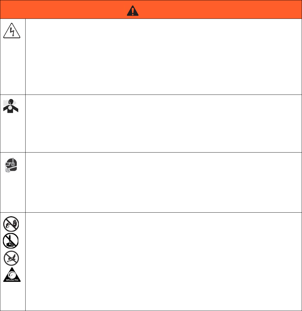
WARNING
ELECTRIC SHOCK HAZARD
This equipment must be grounded. Improper grounding, setup, or usage of the system can cause elec-
tric shock.
• Turn off and disconnect power at main switch before disconnecting any cables and before servicing
equipment.
• Connect only to grounded power source.
• All electrical wiring must be done by a qualified electrician and comply with all local codes and reg-
ulations.
TOXIC FLUID OR FUMES HAZARD
Toxic fluids or fumes can cause serious injury or death if splashed in the eyes or on skin, inhaled, or
swallowed.
• Read MSDSs to know the specific hazards of the fluids you are using.
• Store hazardous fluid in approved containers, and dispose of it according to applicable guidelines.
• Always wear chemically impermeable gloves when spraying, dispensing, or cleaning equipment.
PERSONAL PROTECTIVE EQUIPMENT
You must wear appropriate protective equipment when operating, servicing, or when in the operating
area of the equipment to help protect you from serious injury, including eye injury, hearing loss, inhala-
tion of toxic fumes, and burns. This equipment includes but is not limited to:
• Protective eyewear, and hearing protection.
• Respirators, protective clothing, and gloves as recommended by the fluid and solvent manufacturer.
+
SKIN INJECTION HAZARD
High-pressure fluid from dispensing device, hose leaks, or ruptured components will pierce skin. This
may look like just a cut, but it is a serious injury that can result in amputation. Get immediate surgical
treatment.
• Do not point dispensing device at anyone or at any part of the body.
• Do not put your hand over the fluid outlet.
• Do not stop or deflect leaks with your hand, body, glove, or rag.
• Follow the Pressure Relief Procedure when you stop dispensing and before cleaning, checking,
or servicing equipment.
• Tighten all fluid connections before operating the equipment.
• Check hoses and couplings daily. Replace worn or damaged parts immediately.
Warnings
3A2175A 11
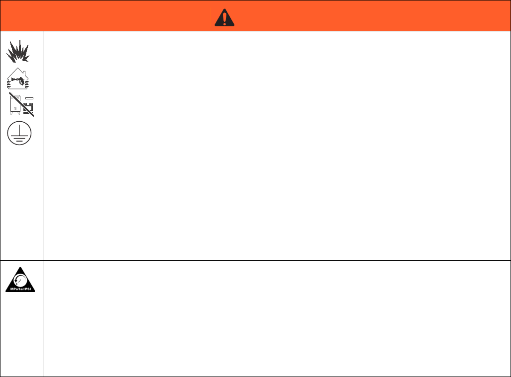
FIRE AND EXPLOSION HAZARD
Flammable fumes, such as solvent and paint fumes, in work area can ignite or explode. To help prevent
fire and explosion:
• Use equipment only in well ventilated area.
• Eliminate all ignition sources; such as pilot lights, cigarettes, portable electric lamps, and plastic
drop cloths (potential static arc).
• Keep work area free of debris, including solvent, rags and gasoline.
• Do not plug or unplug power cords, or turn power or light switches on or off when flammable fumes
are present.
• Ground all equipment in the work area. See Grounding instructions.
• Use only grounded hoses.
• Hold gun firmly to side of grounded pail when triggering into pail.
• If there is static sparking or you feel a shock, stop operation immediately. Do not use equipment
until you identify and correct the problem.
• Keep a working fire extinguisher in the work area.
PRESSURIZED EQUIPMENT HAZARD
Fluid from the gun/dispense valve, leaks, or ruptured components can splash in the eyes or on skin and
cause serious injury.
• Follow the Pressure Relief Procedure when you stop spraying and before cleaning, checking, or
servicing equipment.
• Tighten all fluid connections before operating the equipment.
• Check hoses, tubes, and couplings daily. Replace worn or damaged parts immediately.
WARNING
Warnings
12 3A2175A
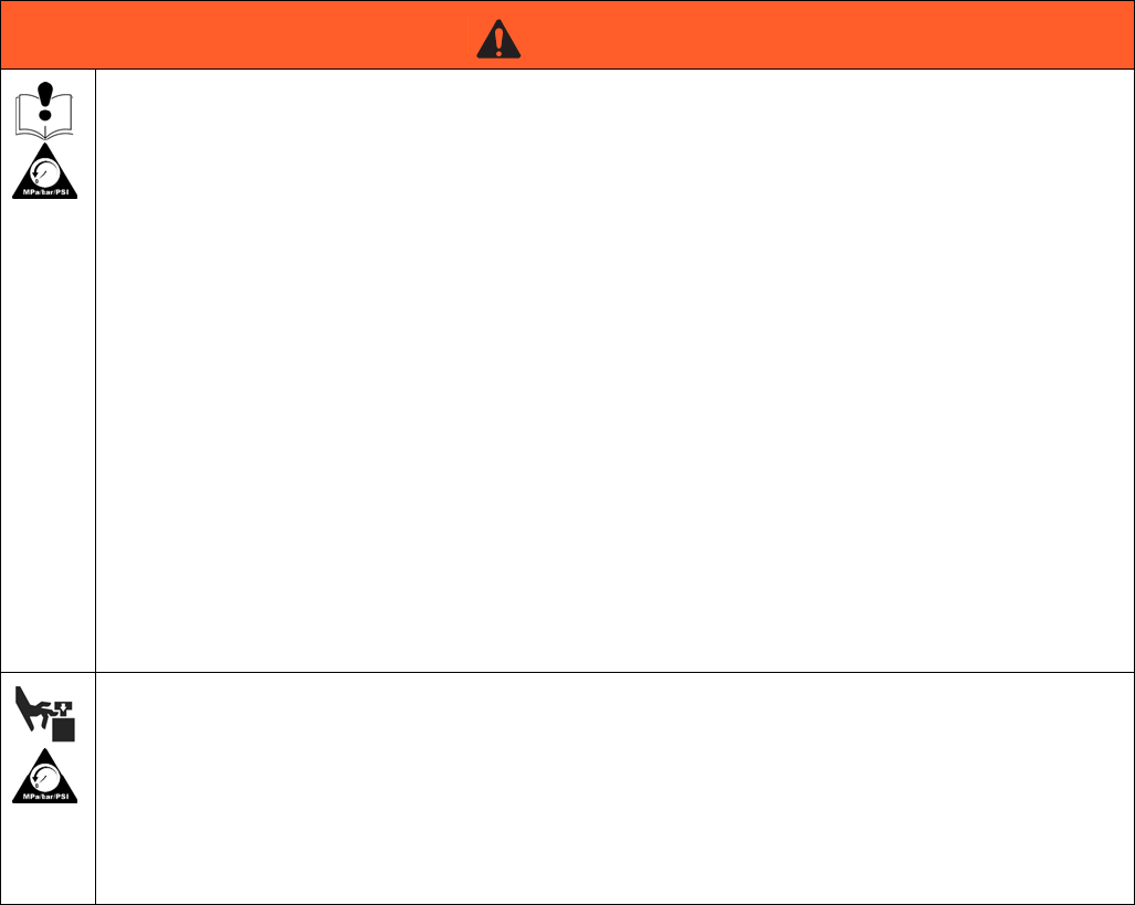
EQUIPMENT MISUSE HAZARD
Misuse can cause death or serious injury.
• Do not operate the unit when fatigued or under the influence of drugs or alcohol.
• Do not exceed the maximum working pressure or temperature rating of the lowest rated system
component. See Technical Data in all equipment manuals.
• Use fluids and solvents that are compatible with equipment wetted parts. See Technical Data in all
equipment manuals. Read fluid and solvent manufacturer’s warnings. For complete information
about your material, request MSDS from distributor or retailer.
• Do not leave the work area while equipment is energized or under pressure. Turn off all equipment
and follow the Pressure Relief Procedure when equipment is not in use.
• Check equipment daily. Repair or replace worn or damaged parts immediately with genuine manu-
facturer’s replacement parts only.
• Do not alter or modify equipment.
• Use equipment only for its intended purpose. Call your distributor for information.
• Route hoses and cables away from traffic areas, sharp edges, moving parts, and hot surfaces.
• Do not kink or over bend hoses or use hoses to pull equipment.
• Keep children and animals away from work area.
• Comply with all applicable safety regulations.
MOVING PARTS HAZARD
Moving parts can pinch, cut or amputate fingers and other body parts.
• Keep clear of moving parts.
• Do not operate equipment with protective guards or covers removed.
• Pressurized equipment can start without warning. Before checking, moving, or servicing equip-
ment, follow the Pressure Relief Procedure and disconnect all power sources.
WARNING

Warnings
3A2175A 13
Important Two-Component Material Information
14 3A2175A
Important Two-Component Material Information
Isocyanate Conditions
Material Self-ignition
Keep Components A (Red) and
B(Blue) Separate
Moisture Sensitivity of
Isocyanates
Isocyanates (ISO) are catalysts used in two component
foam and polyurea coatings. ISO will react with moisture
(such as humidity) to form small, hard, abrasive crystals,
which become suspended in the fluid. Eventually a film
will form on the surface and the ISO will begin to gel,
increasing in viscosity. If used, this partially cured ISO
will reduce performance and the life of all wetted parts.
NOTE: The amount of film formation and rate of crystal-
lization varies depending on the blend of ISO, the
humidity, and the temperature.
To prevent exposing ISO to moisture:
• Always use a sealed container with a desiccant
dryer in the vent, or a nitrogen atmosphere. Never
store ISO in an open container.
• Keep the ISO lube pump reservoir (if installed) filled
with IsoGuard Select™, part 24F516. The lubricant
creates a barrier between the ISO and the atmo-
sphere.
• Use moisture-proof hoses specifically designed for
ISO, such as those supplied with your system.
• Never use reclaimed solvents, which may contain
moisture. Always keep solvent containers closed
when not in use.
• Never use solvent on one side if it has been contam-
inated from the other side.
• Always lubricate threaded parts with ISO pump oil
or grease when reassembling.
Spraying or dispensing materials containing isocya-
nates creates potentially harmful mists, vapors, and
atomized particulates.
Read material manufacturer’s warnings and material
MSDS to know specific hazards and precautions
related to isocyanates.
Prevent inhalation of isocyanate mists, vapors, and
atomized particulates by providing sufficient ventila-
tion in the work area. If sufficient ventilation is not
available, a supplied-air respirator is required for
everyone in the work area.
To prevent contact with isocyanates, appropriate per-
sonal protective equipment, including chemically
impermeable gloves, boots, aprons, and goggles, is
also required for everyone in the work area.
Some materials may become self-igniting if applied
too thickly. Read material manufacturer’s warnings
and material MSDS.
Cross-contamination can result in cured material in
fluid lines which could cause serious injury or dam-
age equipment. To prevent cross-contamination of
the equipment’s wetted parts, never interchange
component A (Red) and component B (Blue) parts.
A (Red) and B (Blue) Components
3A2175A 15
Changing Materials
• When changing materials, flush the equipment mul-
tiple times to ensure it is thoroughly clean.
• Always clean the fluid inlet strainers after flushing.
• Check with your material manufacturer for chemical
compatibility.
• Most materials use ISO on the A (Red) side, but
some use ISO on the B (Blue) side. See the follow-
ing section.
A (Red) and B (Blue) Components
IMPORTANT!
Material suppliers can vary in how they refer to plural
component materials.
Be aware that when standing in front of the manifold on
proportioner:
• Component A (Red) is on the left side.
• Component B (Blue) is on the right side.
For all machines:
• The A (Red) side is intended for ISO, hardeners,
and catalysts.
• If one of the materials being used is moisture-sensi-
tive, that material should always be in the A (Red)
side.
• The B (Blue) side is intended for polyols, resins, and
bases.
For HFRS Systems:
The high volume material is typically the ISO and is
located on the A (Red) side. Some material chemistries
may have an ISO which is the low volume material. The
ISO must always be in the A (Red) side containing the
Isolube.
For HFRL Systems:
The high volume material will always be the B (Blue)
side.Typical Installation
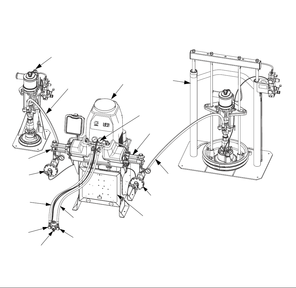
Typical HFRS System
16 3A2175A
Typical HFRS System
Key:
A HFR Unit (Silicone)
B Power Module
CB “Blue” Pump
D A ”Red” Pump
E Outlet Module
F B Hose Kit
G A Hose Kit
H Dispense Gun
J Orifice Block
K Orifice, 1/4”
L Supply Unit, B Side
M Supply Unit, A Side
N Supply Hose
P Inlet Regulator
FIG. 1: HFR Silicone System
M
ti18208a
N
D
P
E
A
C
P
L
B
F
G
J,
H
J,
N
KK
Typical HFRL System
3A2175A 17
Typical HFRL System
Key:
AA HFR Unit (Laminate)
AB Power Module
AC B “Blue” Pump
AD A “Red” Pump
AE Outlet Module
AF B Hose Kit
AG A Hose Kit
AH Dispense Gun
AJ Orifice Block
AK Orifice, 1/4”
AL Inlet Assembly
AM Isolube Kit (not shown)
FIG. 2: HFR Laminate System
ti18209a
AA
AC
AD
AL
AE
AG
AF
AJ,
AB
AK
AL
AH
Component Identification
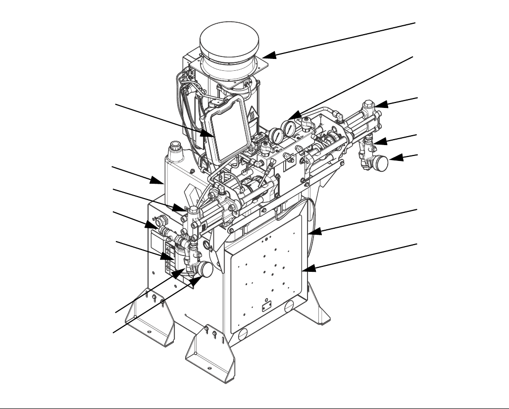
18 3A2175A
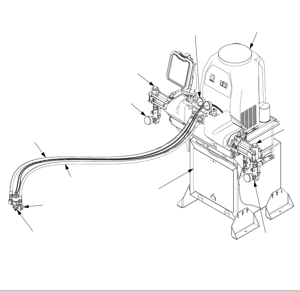
Component Identification
Key for FIG. 4.
BA Advanced Display Module (see page 24)
BB Component A (Red) Pressure Relief Outlet
BC Component B (Blue) Pressure Relief Outlet
BD Component A (Red) Fluid Manifold Inlet (on left side of manifold
block)
BE Component B (Blue) Fluid Manifold Inlet
BF HFR Fluid Manifold
BG Feed Inlet Pressure Gauge
BH Feed Inlet Strainer (standard filter size is 20 mesh)
BJ Feed Inlet Valve (A (Red) side shown)
BK Component A (Red) Outlet Pressure Gauge
BL Component B (Blue) Outlet Pressure Gauge
BM Component A (Red) Hose Connection (from feed to gun or mix
head)
BN Component B (Blue) Hose Connection (from feed to gun or mix
head)
BP Hydraulic Power Pack Assembly
BR Hydraulic Tank
BS IsoGuard™ Select Fluid Reservoir (included on all HFRL,
available separately as kit 24M154 for HFRS)
BT Pumpline Linear Sensor
BU Motor Control Module, see page 22
BV Main Power Switch
BW Component A (Red) Pump
BX Component B (Blue) Pump
BY Power Distribution Box
BZ Component A (Red) PRESSURE RELIEF/DISPENSE Valve
CA Component B (Blue) PRESSURE RELIEF/DISPENSE Valve
CB Component A (Red) Pressure Transducer
CC Component B (Blue) Pressure Transducer
CD Material Pressure Regulator Component A (Red)
CE Power Distribution Box
FIG. 3: Component Identification, shown with shrouds removed
BA
ti18210a
BR
BJ
BS
BH
BG
BX
BP
BH
BG
CE
BY
BF
BV
(Located on
opposite side
of machine)
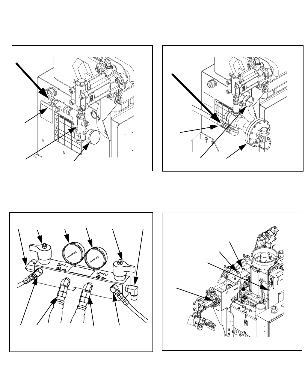
Component Identification
3A2175A 19
FIG. 4: Component Identification, shown with shrouds removed
ti9880a1
Fluid Manifold (FM) Detail
BU
CC
CB
Rear View
24C352_313998_4e
HFRL Material Inlet
(250 psi Max)
HFRS Material Inlet
(3000 psi Max)
ti18211a ti18212a
BJ
BH BG
BJ
BJ
CD BG
BZBD CABLBK BE
BMBB BCBN
BT
Component Identification
20 3A2175A
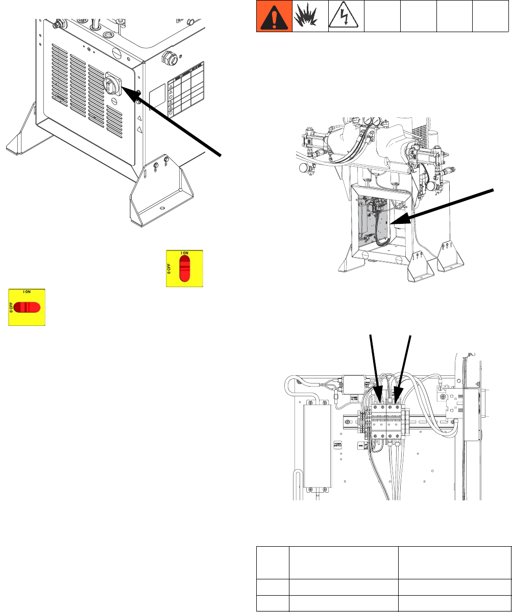
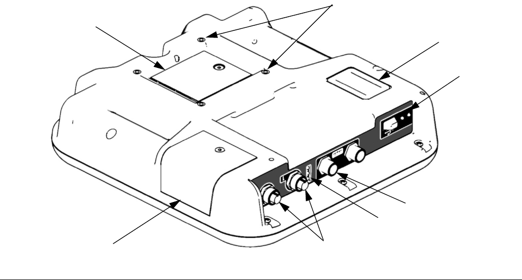
Main Power Switch
Located on rear of machine.
The main power switch turns power ON and
OFF . The main power switch does not turn
pumps on.
Circuit Breakers
The circuit breakers are located on the panel assembly
mounted directly behind the disconnect switch panel on
the right side of the enclosure. For more information
about items on the power distribution panel, see manual
3A2176
ti18213a
Ref.
230V/ 1 phase,
400V/ 3 phase Component
CB1 63A Motor Control Module
CB5 5A Miscellaneous
ti18215a
ti18214a
CB1
CB5
Component Identification
3A2175A 21
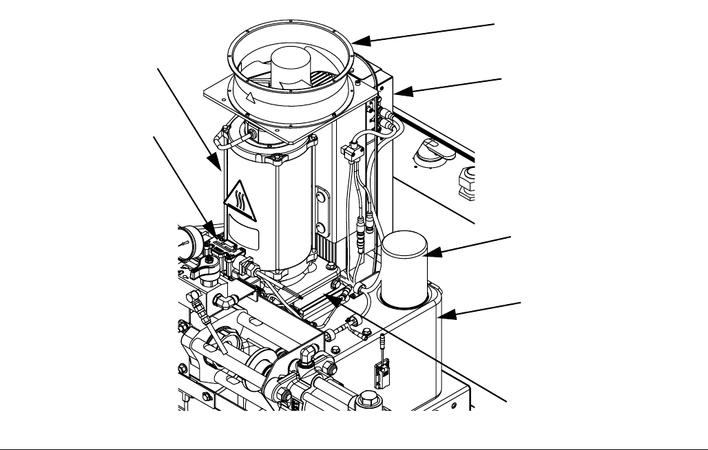
Hydraulic Power Pack
Key:
DA 8 Gallon Hydraulic Oil Reservoir (see Accessories on
page 91 for specifications)
DB Electric Motor
DC Dipstick (not shown, located at rear left of hydraulic tank)
DD Hydraulic Housing
DE Directional Valve
DF Motor Control Module (see page 22)
DG Fan
DH Filter
DJ Shroud (not shown, removed for clarity)
FIG. 5
DA
DG
DE
DD
DH
DB
DF
24C352 313998 2g
Component Identification
22 3A2175A
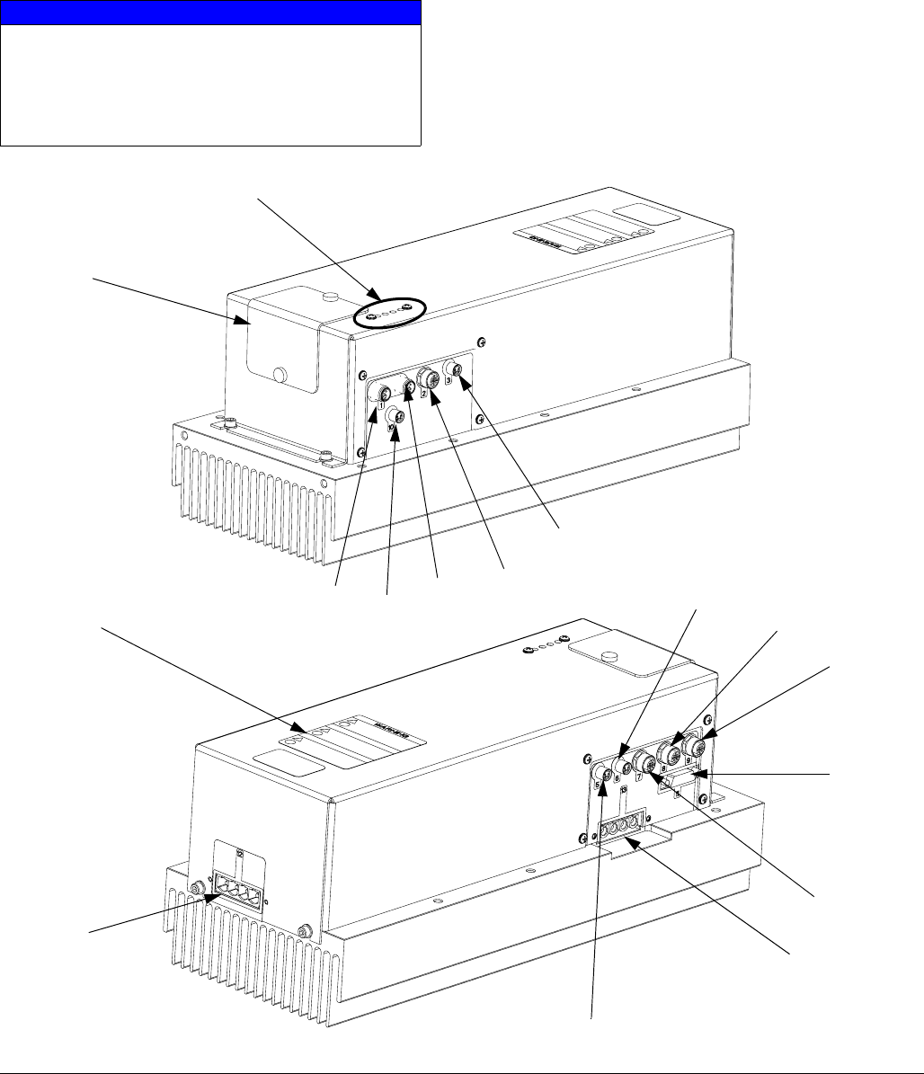
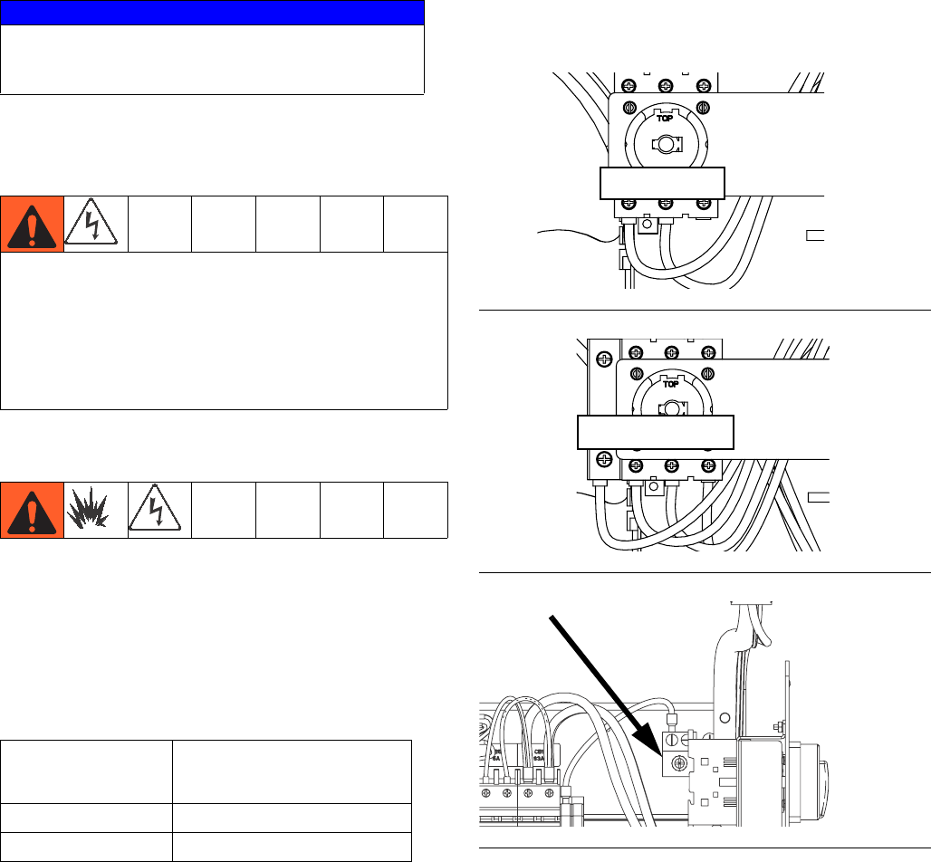
Motor Control Module (MCM)
For MCM location, see reference MA in FIG. 4 on
page 19. When installed, the end of the MCM with the
power input connection (12) faces down and the end
with the access cover (A) faces up.
The Motor Control Module uses an 8-position selector
switch to set the system maximum working pressure.
NOTICE
If the Motor Control Module is replaced, the selec-
tor switch must be set prior to initial startup of the
Motor Control Module or damage may occur. See
HFR Repair manual for details, see Related Man-
uals on page 3.
FIG. 6: MCM Component Identification
A
r_257396_3b9905_01b
r_257396_3b9905_03b
C
12
B
13
1A
11
1B
5
7
6
8
9
10
2
3

Component Identification
3A2175A 23
Ref Description
A Access Cover
BLEDs
C Warning Label
1A, 1B CAN Connections
2 Three-way Splitter to: Oil Low Level
Sensor, Dispense Valve Solenoid, and
Footswitch
3 Oil Temperature Sensor
5 Electric Motor Temperature Sensor
6LVDT
7 Three-way Splitter to:
Hydraulic Directional Valve,
Oil Overtemperature Switch
8 Pressure Transducer B (Blue) side
9 Pressure Transducer A (Red) side
10 Not used
11 Motor Position Sensor
12 MCM Power Input Connection
13 Motor Power Connection
Component Identification
24 3A2175A
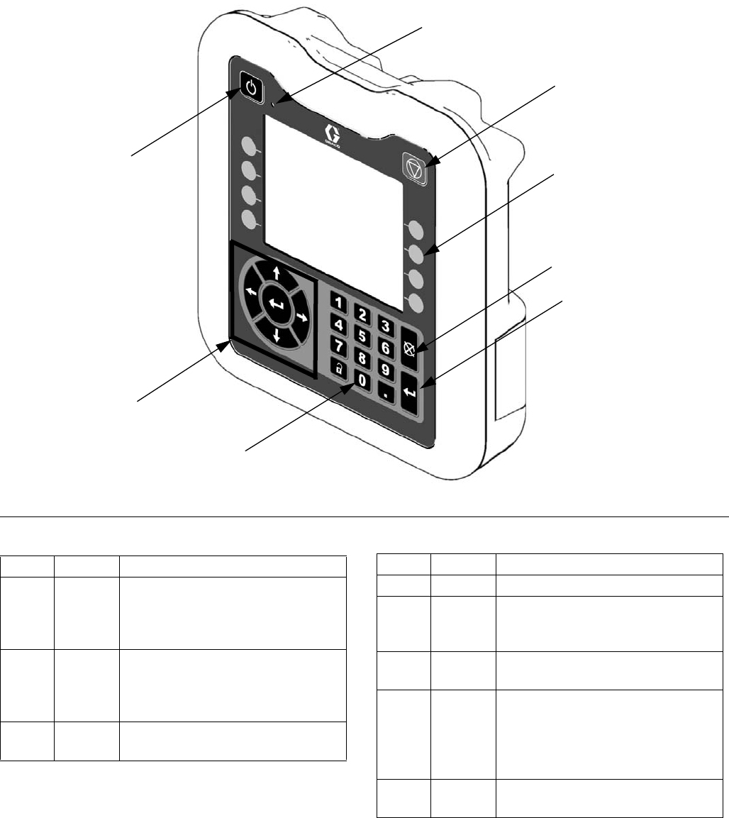
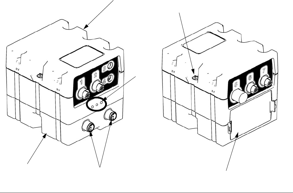
Advanced Display Module (ADM)
User Interface
Buttons
FIG. 7: ADM Component Identification - Front
TI12362a1
EA
EB
EC
EE
EH
EG
EF
ED
Callout Button Function
EA System
enable/
disable
Enables/disables system. When
system is disabled, temperature
control and dispense operation are
disabled.
EB System
Status
Indicator
Light
Displays system status. See Sys-
tem Status Indicator (CB) Condi-
tions on page 25 for details.
EC Stop Stop all system processes. Is not a
safety or emergency stop.
ED Soft Keys Defined by application using ADM.
EE Cancel Cancel a selection or number entry
while in the process of entering a
number or making a selection.
EF Enter Acknowledge changing a value or
making a selection.
EG Lock/Set
up
Toggle between run and setup
screens. If setup screens are pass-
word protected, button toggles
between run and password entry
screen.
EH Naviga-
tion
Navigate within a screen or to a
new screen.
Callout Button Function
Component Identification
3A2175A 25
Key:
EJ Flat Panel Mount
EK Model Number
EL USB Module Interface
EM CAN Cable Connections
EN Module Status LEDs
EP Accessory Cable Connections
ER Token Access Cover
ES Battery Access Cover
System Status Indicator (CB) Conditions
Green Solid - Run Mode, System On
Green Flashing - Setup Mode, System On
Yellow Solid - Run Mode, System Off
Yellow Flashing - Setup Mode, System Off
FIG. 8: ADM Component Identification - Rear
ER
EK
EJ
EL
EP
EN
EM
ES
ti12363a1

Component Identification
26 3A2175A
Main Display Components
The following figure calls out the navigational, status, and general informational components of each screen. For
details regarding the user interface display see Advanced Display Module (ADM) Operation, page 55.
FIG. 9: Main Display Components
Current date and time Current screen
Enter/Exit screen
Previous screen Next screen
Function display
Current
screen no.
Next
screen no.
Previous
screen no.
Mode Faults, Status
Component Identification
3A2175A 27
Fluid Control Module (FCM)
Key:
FA Fluid Control Module
FB Base
FC Module Connection Screws
FD Access Cover
FE Module Status LEDs
FF CAN Connectors
FIG. 10
ti12337a1 ti12336a1
FA
E
FB
FC
FD
FF
Dispense Valve Overview
28 3A2175A
Dispense Valve Overview
The HFRL and HFRS systems will be provided exclu-
sively with MD2 dispense valves.
The MD2 dispense valve is an example of a solenoid
controlled dispense valve. When the trigger is pulled the
signal requests the dispense to start. When the machine
sees the signal, fluid rises to dispensing pressure and
the valve is opened to begin dispensing. When the trig-
ger is released, the solenoid signals that the dispense is
finished.
Setup
3A2175A 29
Setup
Perform this setup procedure to secure all necessary
machine connections for machine operation.
1. Locate HFR.
a. Locate HFR on a level surface. See Dimen-
sions on page 94 for space requirements.
b. Do not expose HFR to rain.
2. Electrical requirements. See Models on page 4
for detailed electrical requirements information.
3. Connect electrical cord.
NOTE: See Power Line Voltage Surges information on
page 30.
NOTE: Power cord is not supplied. See the following
table.
† Residual Current Device (RCD) must be rated at
300 mA if installed.
Electrical Cord Wires by Model
230V, 1 phase: L1, L2, GND
400V, 3 phase: L1, L2, L3, N, GND
Use 5/32 or 4 mm hex allen wrench to connect the two
or three power leads to L1, L2, and L3, as applicable.
Connect green to ground (GND).
Electrical Cord Wires by Model
230V, 1phase: L1, L2, (L3 - No Connection), GND
400V, 3 phase: L1, L2, L3, N, GND
NOTICE
To avoid machine damage and personal injury,
ensure the machine is securely strapped to the pallet
to prevent tipping before lifting.
Installing this equipment requires access to parts
which may cause electric shock or other serious injury
if work is not performed properly. Have a qualified
electrician connect power and ground to main power
switch terminals, see step 3 in this setup procedure.
All electrical wiring must be done by a qualified electri-
cian and comply with all local codes and regulations.
Table 1: Power Cord Requirements
Model
Cord Requirements
AWG (mm2)
230V, 1 phase 6 (13.3), 2 wire + ground
400V, 3 phase 6 (13.3), 4 wire + ground †
FIG. 11: 230V, 1 phase shown
FIG. 12: 400V, 3 phase shown
FIG. 13: Grounding Lug
L1 L2 L3
L1 L2 L3N
Setup
30 3A2175A
Power Line Voltage Surges
Power conversion equipment can be sensitive to voltage
fluctuations on incoming power. The Motor Control Mod-
ule falls under the category of power conversion equip-
ment because energy is stored on a capacitive bus and
then modulated to control a brushless motor. Engi-
neered design takes this into account and withstands a
wide range of conditions, but it is possible for supplied
power to occasionally fall outside the tolerable range in
industrial plants with high-amperage reactive pulsed
loads such as welding equipment. If the tolerable range
is exceeded, an overvoltage condition is flagged and the
system will shut down in an alarm state to protect itself
and alert the user of unstable power. Excessive or
repeated overvoltage may permanently damage hard-
ware.
The MAX-HOLD feature on a multimeter can be used to
determine peak DC voltage on the line. DC is the proper
setting, as opposed to AC, because peak voltage is the
critical parameter that affects the DC voltage level
stored on the capacitive bus in power conversion equip-
ment. Reading should not regularly exceed approxi-
mately 400VDC to avoid tripping the 420VDC alarm
level in the Motor Control Module. If power quality is sus-
pect, power conditioning or isolation of the device(s)
causing poor power quality is recommended. Consult a
qualified electrician if there are any concerns about the
available power supply.
Power Line Test Steps with Multimeter
a. Set multimeter to “DC voltage”.
b. Connect multimeter probes to supplied power
line.
c. Press “Min Max” successively to show the peak
positive and negative DC voltages.
d. Confirm readings do not exceed 400VDC
(Motor Control Module alarm issued at
420VDC).
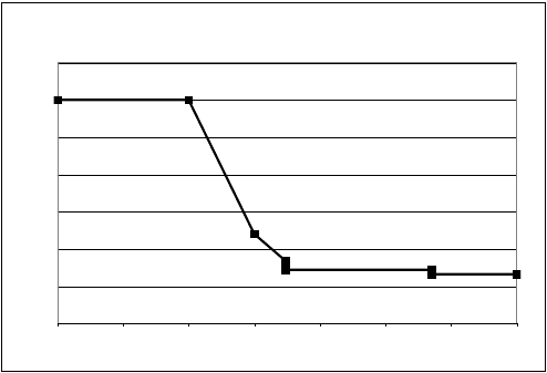
The chart below shows the permissible magnitude and
duration of temporary over-voltage events:
Maximum Permissible Transient Voltage Surges
* Constructed from ITIC 1996 curve, referenced by IEC 61000-2-4
1200Vac, 1697Vdc
264Vac, 373Vdc
336Vac, 475Vdc
288Vac, 407Vdc
480Vac, 679Vdc
<--1 MW Max Surge Power
<--150 KW Max Surge Power
<--50 KW Max Surge Power <--No Power Limit
0
200
400
600
800
1000
1200
1400
Time (seconds)
Voltage (Volts RMS)
0.000001 0.00001 0.0001 0.001 0.01 0.1 1 10
Setup
3A2175A 31
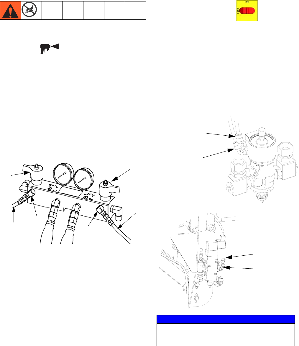
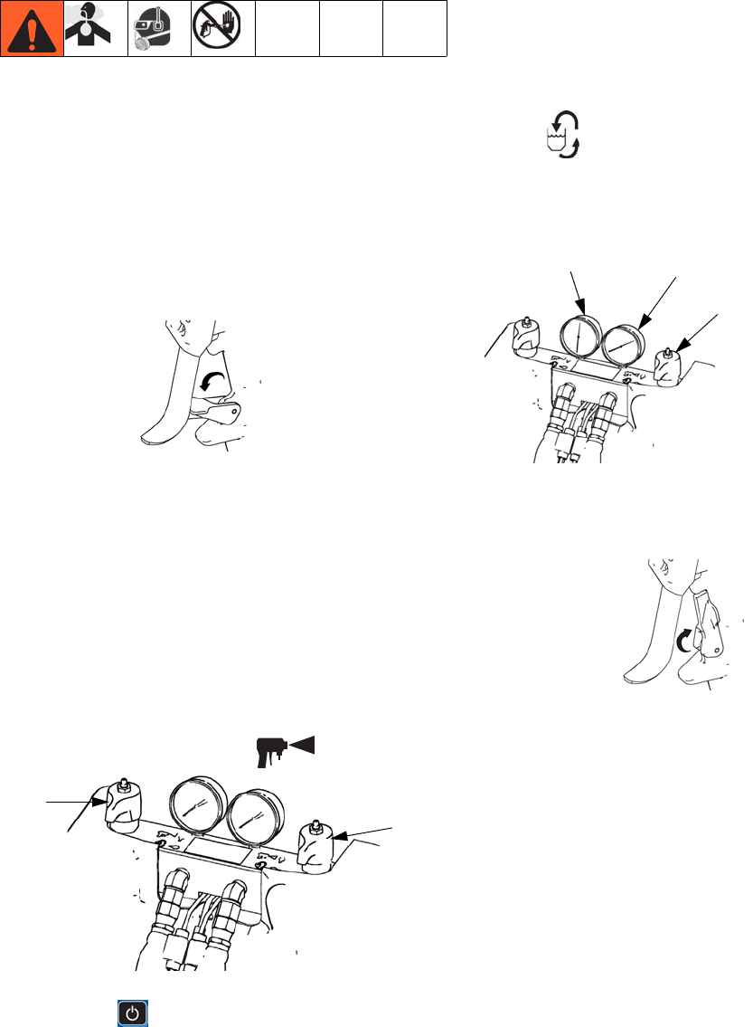
4. Connect regulator assemblies (If Equipped)
NOTE: Systems equipped with a fluid regulator on the
material inlet will not be fully assembled due to shipping.
The regulator assembly will be detached and boxed
separately.
a. Attach the male nipple located on the regulator
assembly to the female swivel located on the
end of the pump assembly.
b. Connect the air tube to the tee fitting on the
power valve assembly located on the right side
of the machine.
5. Connect feed pumps (HFRL)
a. Install feed pumps in component A (Red) and B
(Blue) supply drums. See FIG. 1 and FIG. 4,
pages 16 and 19.
NOTE: A minimum feed pressure of 50 psi (0.35 MPa,
3.5 bar) is required at both feed inlet pressure gauges
(FP). Maintain A (Red) and B (Blue) feed pressures
within 10% of each other.
b. Ensure A (Red) and B (Blue) inlet valves (FV)
are closed.
c. Adjust the fluid pressure regulator so the pres-
sure gauge reads zero.
NOTE: Supply hoses from feed pumps should be 3/4 in.
(19 mm) ID minimum.
d. Connect and tighten component B (Blue) supply
hose to the 3/4 npt(f) swivel on the component B
(Blue) inlet assembly.
e. Connect and tighten component A (Red) supply
hose to the 3/4 NPT(f) swivel on the component
A (Red) inlet assembly.
pressure
ti18216a
gauge
250 psi max inlet
pressure
3000 psi max
inlet pressure
ti9883a1
FV
ti18217a
Setup
32 3A2175A
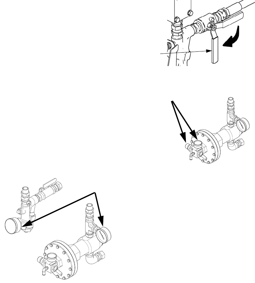
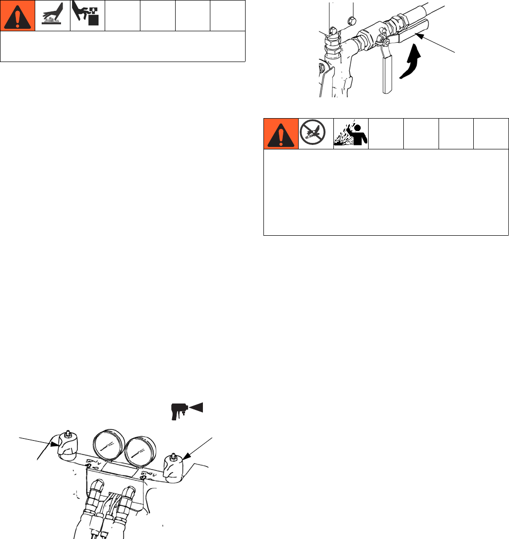
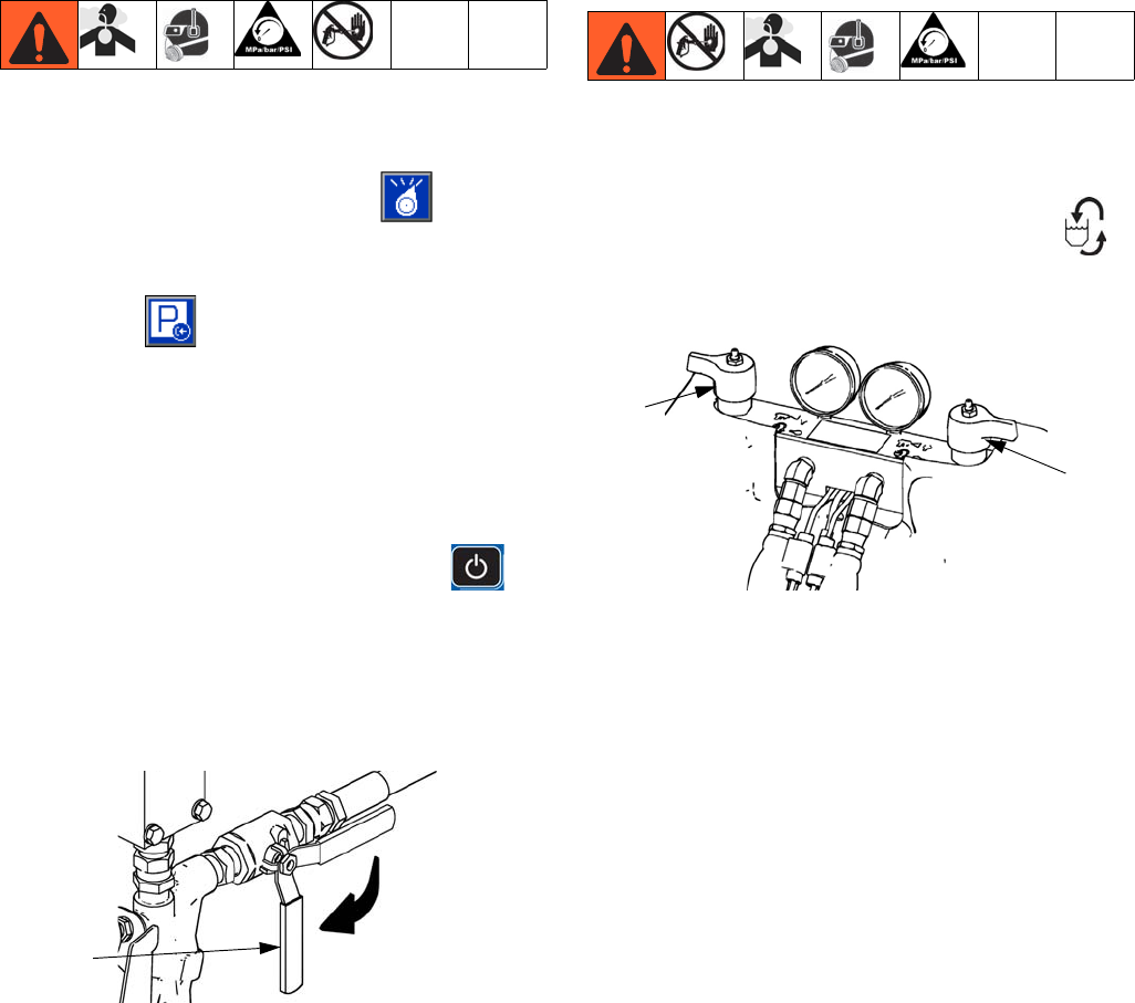
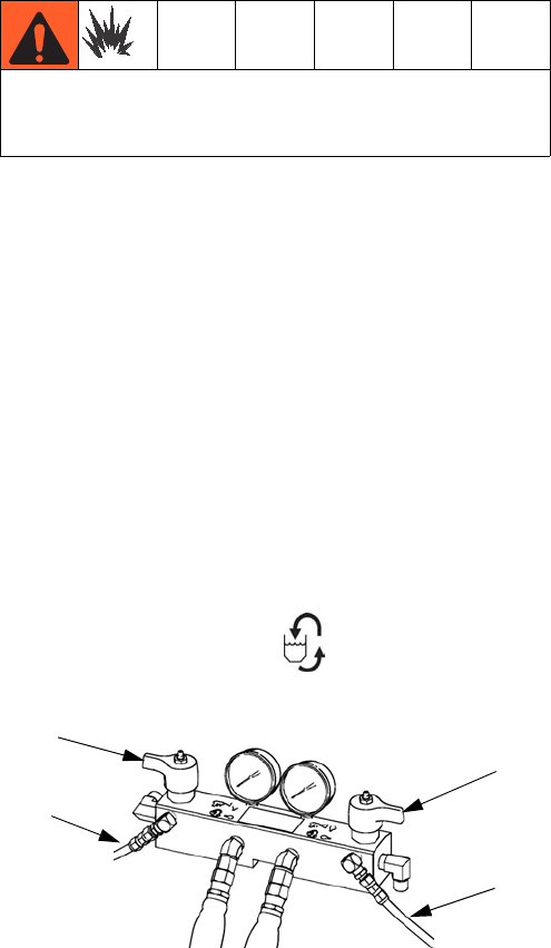
6. Connect pressure relief lines (R)
a. Recommended: Connect high pressure hose
(R) to relief fittings (BA, BB) of both PRES-
SURE RELIEF/DISPENSE valves. Secure sup-
plied bleed tubes (N) in grounded, sealed waste
containers (H). See FIG. 1, page 16.
7. Connect hose
a. Turn main power OFF .
b. Assemble fluid supply hose sections and whip
hose.
c. Connect A (Red) and B (Blue) hoses to A (Red)
and B (Blue) outlets on HFR fluid manifold (FM).
Hoses are color coded: red for component A,
blue for component B. Fittings are sized to pre-
vent connection errors.
8. Connect air tubes from solenoid valve to MD2.
a. Route the airlines following the material hoses.
Do not install shutoffs downstream of the PRESSURE
RELIEF/DISPENSE valve outlets (BA, BB). The
valves function as overpressure relief valves when set
to DISPENSE . Lines must be open so valves
can automatically relieve pressure when machine is
operating.
If circulating fluid back to the supply drums, use high
pressure hose rated to withstand the maximum work-
ing pressure of this equipment.
ti9880a1
BA
BB
R
R
SB
SA
NOTICE
To avoid improper machine operation, ensure the
open and close ports of the MD2 are connected to
the proper open and close ports of the valve.
OPEN
CLOSED
OPEN
CLOSED
Setup
3A2175A 33
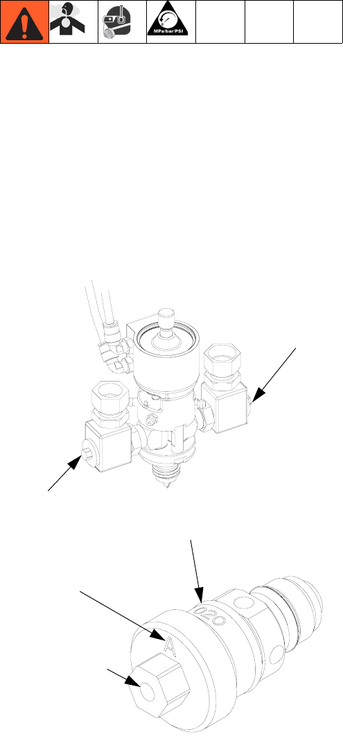
9. Connect whip hose to MD2 valve component A
(Red) and component B (Blue) fluid inlets.
10.Pressure check hose
Pressure check hoses for leaks. If no leaks, secure the
hoses and airlines together to protect from damage.
11.Ground system
a. HFR: grounded through power cord. See step 3
on page 29.
b. Fluid supply containers: follow your local code.
c. Object being dispensed: follow your local code.
d. Solvent pails used when flushing: follow your
local code. Use only metal pails, which are con-
ductive, placed on a grounded surface. Do not
place pail on a nonconductive surface, such as
paper or cardboard, which interrupts grounding
continuity.
e. To maintain grounding continuity when flushing
or relieving pressure, hold a metal part of dis-
pense gun firmly to the side of a grounded
metal pail, then trigger gun.
12.Check hydraulic fluid level
Hydraulic reservoir is filled at the factory. Check fluid
level before operating the first time, and weekly thereaf-
ter. See Accessories on page 91 for specifications.
13.IsoGuard Select Fluid system setup
(Not included on HFRS models)
Component A (Red) Pump: Fill IsoGuard Select reser-
voir (LR) with IsoGuard Select fluid (provided by Graco).
a. Lift the reservoir (LR) out of the bracket (RB)
and remove the container from the cap.
b. Fill with fresh fluid. Thread the reservoir onto
the cap assembly and place it in the
bracket (RB).
c. Push the supply tube approximately 1/3 of the
way into the reservoir. The supply tube is the
tube with the check valve with an arrow pointing
in the direction of flow towards the IsoGuard
Select fluid cylinder.
d. Push the return tube into the reservoir until it
reaches the bottom. The return tube is the tube
with the check valve with an arrow pointing in
the direction of flow away from the IsoGuard
Select fluid cylinder.
NOTE: The return tube must reach the bottom of the
reservoir to ensure that isocyanate crystals will settle to
the bottom and not be siphoned into the supply tube and
returned to the pump.
14. Prime IsoGuard Select fluid cylinder
The IsoGuard Select fluid cylinder must be primed when
replacing IsoGuard Select fluid. See IsoGuard Select™
System on page 47 for instructions.
This equipment must be grounded.
LR
RB
24C352_313998_8e
Setup
34 3A2175A
15. Install dispense valve
a. Navigate to System Screen 2 and select the
MD2 dispense valve from the “Dispense Valve”
drop down menu. See System Screen 2 on
page 62.
b. Set pressure relief valves (SA, SB) to RELIEF.
c. If dispense valve has a trigger safety lock,
engage the trigger safety lock.
d. Connect gun to machine. Verify gun is ready for
operation. See appropriate gun manual listed in
Related Manuals on page 3 for detailed
instructions.
e. Verify airline is connected to the dispense valve
then open bleed-type master air line valve.
f. Set PRESSURE RELIEF/DISPENSE valves
(SA, SB) to DISPENSE .
g. Press to enable system. LED should be
solid green.
h. Check fluid pressure display and adjust as nec-
essary.
i. If equipped, check fluid pressure gauges (GA,
GB) to ensure proper pressure balance. If
imbalanced, reduce pressure of higher compo-
nent by slightly turning PRESSURE
RELIEF/DISPENSE valve for that component
toward PRESSURE RELIEF/CIRCULATION
, until gauges show balanced pressures.
NOTE: For systems without gauges, pressures can be
monitored on the home screen of the ADM.
j. If dispense valve has a trigger safety lock, dis-
engage the trigger safety lock.
k. Perform mix ratio test using two tared cups.
Weigh the cups and divide the weights to verify
the mix ratio by weight. See Ratio Checking
section in the dispense valve manual for more
information.
l. Equipment is ready to dispense.
ti10442a1
LOCKED
ti9877a1
SA
SB
In this example, B (Blue)
side pressure is higher,
so use the B (Blue) side
valve to balance pres-
sures.
ti9877a1
GA GB
ti10441a1
UNLOCKED
Operation
3A2175A 35
Operation
Startup
1. Use feed pumps to load fluid
NOTE: The HFR is tested with oil at the factory. Flush
out the oil with a compatible solvent before dispensing.
See Flushing on page 39.
a. Check that all machine connections are setup.
See Setup procedure, page 29.
b. Verify both feed supply systems and the HFR
are connected to an air supply.
c. Verify the machine is ON.
d. If applicable, check that inlet screens are clean
before daily startup, see page 46.
NOTE: There are no inlet screens on systems equipped
with fluid pressure regulators.
e. If equipped, check level and condition of ISO
lube daily, see IsoGuard Select™ System on
page 47.
f. Turn both PRESSURE RELIEF/DISPENSE
valves (SA, SB) to DISPENSE .
g. Start feed pumps.
h. Open fluid inlet valves (FV), if equipped. Check
for leaks.
i. Prime material regulators with fluid. Refer to
Adjusting Material Inlet Pressure Using the
Material Regulator on page 40.
j. Use feed pumps to load system.
k. Hold MD2 valve nose piece, without a mixer
installed, over two grounded waste containers.
Leave mixer off and trigger gun until both fluids
flow freely from the nose piece without any air.
l. To prime the pump, cycle the pump a few times
or until air-free fluid dispenses.
Do not operate HFR without all covers and shrouds in
place.
ti9877a1
SA SB
Keep Components A (Red) and B (Blue) Separate
Cross-contamination can result in cured material in
fluid lines which could cause serious injury or damage
equipment. To prevent cross-contamination of the
equipment’s wetted parts, never interchange compo-
nent A (Red) and component B (Blue) parts.
FV
ti10002a1
Operation
36 3A2175A
2. Calibrate HFR
The HFR calibration procedure is a two step process.
The first step, Learn Mode, must be performed when-
ever the pump line is rebuilt or if any other maintenance
is performed that may affect the mechanical tolerances
in the pump line. If the machine does not appear to be
utilizing the full extent of the pump stroke, or if the
machine appears to be contacting the end of the
hydraulic cylinder, follow the Learn Mode procedure.
The Learn Mode procedure will teach the system the
mechanical limits of travel.
Learn Mode Procedure:
a. Navigate to the Calibration screen.
b. Place a waste container below the dispense
valve. The next steps will cause the machine to
dispense material.
c. Press the go right button and then the dis-
pense button . The pump will travel to the
right most extreme position.
d. After the pump stops moving, press the go left
button and then press the dispense
button . The pump will travel to the left most
extreme position.
e. After the pump stops moving, press the con-
tinue button to go on to the next step in the
calibration process or the page back button
to return to the main Calibration screen.
NOTE: During this process, the system learned the
mechanical limits of travel. If the pump did not reach
both the left and right extreme limits for any reason,
repeat the procedure.
If the system is to be used in a Time or Volume Dis-
pense Mode, system calibration is complete after the
Learn Mode procedure described above. However, if the
system is to be used in Weight Dispense mode and the
application requires that the dispense amount be accu-
rate and consistent then the weight calibration proce-
dure below must be followed.
Weight Calibration Procedure:
NOTE: Only perform Weight Calibration procedure if the
system will be run in Weight Dispense mode.
The Weight Calibration procedure must be run with the
system production-ready. Orifice sizes and hose lengths
must be finalized, material should be at temperature and
any conditioning zones that will be on during production
should be turned on. Any variation in system setup
between when this procedure is run and the production
environment will result in a decrease in system dispense
accuracy.
a. Navigate to the Weight Calibration screen .
b. Navigate to the Cal. Setpoint text box then enter
the desired set point (pressure or flow, based on
selected Control Mode).
c. Press .
d. Put a waste container under the dispense valve.
e. Press or the footswitch to start the system
characterization process. The pump will start to
operate at the entered setpoint until it learns the
proper control parameters, then repeat the pro-
cess at 60% of that value. When it is complete,
the icon will change back to .
f. Press again to deactivate.
g. Select the Cal. Point 1 of 2 text box under the
scale graphic.
h. With a waste container under the dispense
valve, press or the footswitch to dispense a
Cal. 1 shot. Discard the dispensed material.
Operation
3A2175A 37
i. Select the Cal. 1 Shot Average field then press
to erase the value.
j. Select the Cal. Point 1 of 2 text box.
k. Press or the footswitch to dispense a Cal. 1
shot.
l. Weight the material dispensed and enter the
weight in the text box.
m. Repeat the previous two steps three more
times. The logic will automatically average the
readings and provide the result in the second
text box in the row.
n. Select the Cal. Point 2 of 2 text box under the
scale graphic.
o. Press or the footswitch to dispense a Cal. 2
shot.
p. Weight the dispensed material and enter the
weight in the text box.
q. Repeat the previous two steps three more
times. The logic will automatically average the
readings and provide the result in the second
text box in the row.
r. Press .
The system is now able to dispense accurate material
amounts for the setpoint provided during the process. If
a weight dispense operation uses a setpoint significantly
different from the setpoint used in during calibration an
advisory will be provided to inform the user that the dis-
pense accuracy may be degraded.
3. Set system control and dispense modes: See
System Screen 1 on page 61.
4. Set pump sizes: See System Screen 1 on
page 61.
5. Define Shot Recipes
a. Navigate to the Shots screen.
b. Press to enter the screen.
c. Use the directional keypad to navigate to the
shot detail column for the desired shot number.
d. Type the desired setting for that item then
press .
e. Repeat the previous two steps for all desired
shot numbers.
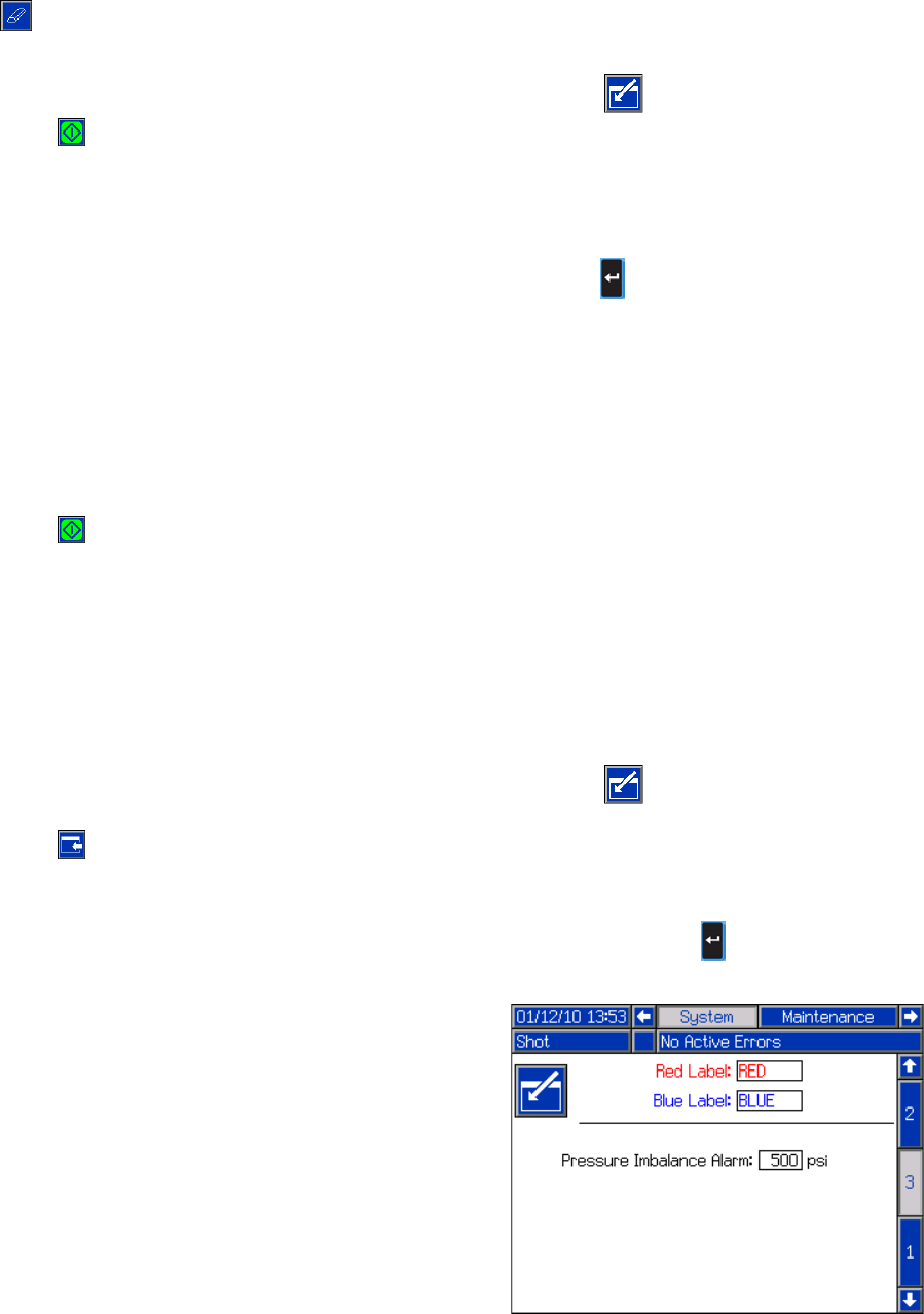
6. Change pressure imbalance setting (optional)
The pressure imbalance function detects conditions that
can cause off-ratio dispense, such as loss of feed pres-
sure/supply, pump seal failure, clogged fluid inlet filter, or
a fluid leak.
The pressure imbalance default is factory-set at 500 psi
(3.4 MPa, 34 bar). For tighter ratio error detection, select
a lower value. For looser detection or to avoid nuisance
alarms, input a higher value.
a. Navigate to System Screen 3.
b. Press to enter the screen.
c. Navigate to the pressure imbalance field.
d. Type the desired pressure imbalance setting
then press Enter .
Operation
38 3A2175A
Shutdown
1. Park pumps.
a. From the Home screen, press and select
Standby mode.
b. Press . Material will dispense. Pump will
park automatically. Once pump is parked, pump
will stop moving.
If a dispense gun with a trigger is installed,
pulling the trigger will begin a park operation.
Material will dispense.
2. Press the enable/disable key on the ADM to
disable the ADM.
3. Turn main power switch (MP) to OFF position.
4. Close A (Red) and B (Blue) fluid supply valves (FV),
if equipped, or remove fluid pressure at supply
device.
5. Perform Pressure Relief Procedure on page 38.
6. Shut down feed pumps as required. See feed pump
manual.
Pressure Relief Procedure
1. Shut off feed pumps and agitator, if used.
2. Turn PRESSURE RELIEF/DISPENSE valves (SA,
SB) to PRESSURE RELIEF/CIRCULATION .
Route fluid to waste containers or supply tanks.
Ensure gauges drop to 0.
3. For models with an dispense valve with a safety
lock, engage gun safety lock.
4. Relieve pressure in dispense valve. See dispense
valve manual.
ti9883a1
FV
ti9879a1
SA
SB
Operation
3A2175A 39
Flushing
• Flush out old fluid with new fluid, or flush out old
fluid with a compatible solvent before introducing
new fluid.
• Use the lowest possible pressure when flushing.
• All fluid components are compatible with common
solvents. Use only moisture-free solvents. See
Accessories on page 91 for list of wetted compo-
nents to verify compatibility of solvent with wetted
materials. See solvent manufacturers information for
material compatibility.
• To flush feed hoses, pumps, and heaters separately
from heated hoses, set PRESSURE RELIEF/DIS-
PENSE valves (SA, SB) to PRESSURE
RELIEF/CIRCULATION . Flush through bleed
lines (N).
• To flush entire system, circulate through gun fluid
manifold (with manifold removed from gun).
• To prevent moisture from reacting with isocyanate,
always leave the system dry or filled with a mois-
ture-free plasticizer or oil. Do not use water. See
Important Two-Component Material Information
on page 14.
•Solvent pails used when flushing: follow your local
code. Use only metal pails, which are conductive,
placed on a grounded surface. Do not place pail on
a nonconductive surface, such as paper or card-
board, which interrupts grounding continuity.
•To maintain grounding continuity when flushing or
relieving pressure, hold a metal part of dispense
gun firmly to the side of a grounded metal pail, then
trigger gun.
Flush equipment only in a well-ventilated area. Do not
dispense flammable fluids. Do not turn on heaters
while flushing with flammable solvents.
SA
SB
ti9880a1
N
N
Operation
40 3A2175A
Adjusting Material Inlet Pressure
Using the Material Regulator
Use the following procedure to adjust the material pres-
sure to the system. This process assumes that the sup-
ply system consisting of a supply pump and outlet hose
has already been loaded and primed and is ready to
provide material to the pump inlet.
1. Verify the air pressure is provided to the material
regulators and that the air gauge on both regulators
are functioning properly.
2. Adjust the air pressure on both material regulators
so that there is no air pressure on them and that the
regulator pressure gauge reads zero.
3. Verify that the material supply pump does not pro-
vide material pressure in excess of 3000 psi
(21 MPa, 207 bar).
4. Verify that there is no pressure in the material sup-
ply pump.
5. Connect the feed hose from material supply system
to the inlet assembly and make sure all fittings are
fluid tight.
6. Gradually increase the air pressure to the supply
pump to provide no more than 3000 psi (21 MPa,
207 bar) material pressure to the inlet regulator
assembly.
7. Place a container at the outlet of the relief lines from
the manifold assembly and secure the lines in place.
8. Place the pressure relief valve on the manifold into
the recirculation position.
9. Slowly increase the air pressure on the material reg-
ulator to allow material to flow though the pump and
out the bleed hose. The required material pressure
will vary depending on the material viscosity and
flow rate.
10. Once material is flowing from the bleed hose, slowly
decrease pressure on the material regulator until
flow stops.
11. Gradually increase pressure to the material regula-
tor until material begins to flow again
12. When material begins to flow out of the bleed port,
close the pressure relief valve.
NOTE: Record the material pressure gauge reading.
Use this pressure as a starting point for adjusting the
material feed pressure to meet application require-
ments.
NOTE: As a general rule for high viscosity materials, the
dispense pressure must exceed the material inlet pres-
sure by 2 to 3 times. Therefore, if the maximum dis-
pense pressure is 2500 psi (17 MPa, 172 bar), the inlet
pressure should be no more than 1250 psi (9 MPa,
86 bar). For lower viscosity, flowable materials, the dis-
pense pressure should exceed the inlet pressure by 3-4
times. Use only enough feed pressure to adequately
feed the HFR pumps.
NOTICE
Care must be taken when applying pressure to sys-
tems equipped with a material pressure regulator
on the inlet assembly. Read both operation and ser-
vice manuals for the pump/ram supply system and
the material pressure regulator prior to loading
material to the HFR system.
NOTICE
Although the material regulator itself is rated for
5000 psi (35 MPa, 345 bar) (, the assembly pro-
vided is only rated for do not exceed 3000 psi
(21 MPa, 207 bar)
NOTICE
The material pressure regulator is not self relieving.
Reducing the material pressure at the regulator will
not effect the pressure reading until the accumu-
lated down stream pressure is relieved. Perform
Pressure Relief Procedure on page 38.
Operation
3A2175A 41
Pressure Balancing Using the
Orifice Valve Assemblies
The MD2 valve for HFRL and HFRS systems is provided
with orifice valve blocks on both of the inlet ports. The
orifice blocks are assembled at the factory with no ori-
fices installed. An orifice kit is provided with a range of
orifice sizes to balance pressures. The orifice size is
etched on the side of the orifice body and there are two
orifices provided in each size. One of the orifices in each
size will be stamped on the hex end with an "A". Use the
orifices stamped with the "A" in the RED side orifice
block. The orifices with no letter etched on the hex end
are to be used on the BLUE side.
Orifices can be installed in one or both orifice blocks as
a tool to increase the outlet pressure in the correspond-
ing material hose. The orifice valves are equipped with a
needle valve that can be adjusted with the provided
allen wrench.
1. Before installing, insert the allen wrench into the hex
end of the orifice valve to adjust the needle position.
2. Verify the needle valve is in the fully open position
by turning counter-clockwise until rotation stops.
After installation, the needle valve can be turned
clockwise to further increase pressure.
NOTE: Always run the material first at the desired flow
rate with no orifice valves installed to evaluate the dis-
pense pressures generated for each material.
NOTE: Appropriate orifice valve selection is essentially
done by trial. The following can help determine if it is
necessary to increase the outlet pressure and help
select an orifice.
a. The outlet pressure for heavy-paste viscosity
materials should be at least 2 times higher than
the z-pump feed pressure (as determined by the
material pressure regulator). Max outlet pres-
sure is equal to 3000 psi (21 MPa, 207 bar) and
the feed pressure should be below 1500 psi
(10 MPa, 103 bar).
b. The outlet pressure for lower viscosity-flowable
materials should be 3-4 times higher than the
z-pump feed pressure. Dispense pressures for
this viscosity range should be in the 750 psi
(5 MPa, 52 bar) to 1000 psi (7 MPa, 69 bar)
range.
c. The outlet pressures of both material hoses
should be as close as possible to each other
and within a suggested range of 10%. See Sys-
tem Screen 3, page 63.
3. Install orifice valves only if the outlet pressure needs
to be increased. See Maintenance starting on page
43 for details.
4. If rule a and b above are met by both materials,
install an orifice valve in the lower pressure side,
only if required to balance the outlet pressures.
5. If neither rule a or rule above are met by either
material, install an orifice valve in both orifice blocks
to raise the pressure and allow pressure balancing.
B ORIFICE
A ORIFICE
SIZE
LOCATION
ADJUSTMENT

Operation
42 3A2175A
NOTE: In general, the flow area ratio of the orifice
valves should be equal to the material ratio, but it will
also be influenced by differences between "A" and "B"
material viscosities and flow characteristics. For flow-
able materials, start with a smaller orifice combination to
increase pressure. For heavy viscosity, paste materials,
start with a larger orifice combination. It is desirable for
the orifice to do the majority of the pressure adjustment,
as this will result in the most stable system. Adjustments
of the needle valve (if used) will require periodic adjust-
ment.
* Item included in kit 24E250
NOTICE
Not properly maintaining the pressure differential
between inlet and dispense pressures may cause
inconsistent pump output. Adjust the needle valves
periodically to maintain pressures.
Available Orifice Flow Area Ratios
Dia-
meter
0.016
0.020*
0.024
0.028
0.031 *
0.035
0.039
0.042
0.047 *
0.052
0.055
0.060 *
0.063
0.067 *
0.073
0.086 *
Flowrate Increases as Diameter Increases=>
0.016 1.0 1.6 2.3 3.1 3.8 4.8 5.9 6.9 8.6 10.6 11.8 14.1 15.5 17.5 20.8 28.9
0.020* 1.6 1.0 1.4 2.0 2.4 3.1 3.8 4.4 5.5 6.8 7.6 9.0 9.9 11.2 13.3 18.5
0.024 2.3 1.4 1.0 1.4 1.7 2.1 2.6 3.1 3.8 4.7 5.3 6.3 6.9 7.8 9.3 12.8
0.028 3.1 2.0 1.4 1.0 1.2 1.6 1.9 2.3 2.8 3.4 3.9 4.6 5.1 5.7 6.8 9.4
0.031* 3.8 2.4 1.7 1.2 1.0 1.3 1.6 1.8 2.3 2.8 3.1 3.7 4.1 4.7 5.5 7.7
0.035 4.8 3.1 2.1 1.6 1.3 1.0 1.2 1.4 1.8 2.2 2.5 2.9 3.2 3.7 4.4 6.0
0.039 5.9 3.8 2.6 1.9 1.6 1.2 1.01.21.51.82.0 2.4 2.6 3.0 3.5 4.9
0.042 6.9 4.4 3.1 2.3 1.8 1.4 1.2 1.0 1.3 1.5 1.7 2.0 2.3 2.5 3.0 4.2
0.047* 8.6 5.5 3.8 2.8 2.3 1.8 1.5 1.3 1.0 1.2 1.4 1.6 1.8 2.0 2.4 3.3
0.052 10.6 6.8 4.7 3.4 2.8 2.2 1.8 1.5 1.2 1.0 1.1 1.3 1.5 1.7 2.0 2.7
0.055 11.8 7.6 5.3 3.9 3.1 2.5 2.01.71.41.11.0 1.2 1.3 1.5 1.8 2.4
0.060* 14.1 9.0 6.3 4.6 3.7 2.9 2.4 2.0 1.6 1.3 1.2 1.01.11.21.52.1
0.063 15.5 9.9 6.9 5.1 4.1 3.2 2.6 2.3 1.8 1.5 1.3 1.1 1.0 1.1 1.3 1.9
0.067* 17.5 11.2 7.8 5.7 4.7 3.7 3.0 2.5 2.0 1.7 1.5 1.2 1.1 1.0 1.2 1.6
0.073 20.8 13.3 9.3 6.8 5.5 4.4 3.5 3.0 2.4 2.0 1.8 1.5 1.3 1.2 1.0 1.4
0.086* 28.9 18.5 12.8 9.4 7.7 6.0 4.9 4.2 3.3 2.7 2.4 2.1 1.9 1.6 1.4 1.0
Flowrate Increases as Diameter Increases =>

Maintenance
3A2175A 43
Maintenance
Change Break-in Oil
After initial break-in, see Table 5 for recommended fre-
quency of oil changes.
Table 2: Frequency of Oil Changes
Grease Circulation Valves With Fusion
Grease (117773)
Check Hydraulic Fluid Level
Check hydraulic fluid level on dipstick. Fluid level must
be between indent marks (IM) on dipstick. Refill as
required with approved hydraulic fluid; see Accessories
on page 91. If fluid is dark in color, change fluid and fil-
ter.
Task Schedule
Change break-in oil in a new unit After first 250
hours of opera-
tion or within 3
months, which-
ever comes first
Inspect hydraulic and fluid lines
for leaks
Daily
If equipped, inspect fluid inlet
strainer screens, page 46
Daily
If equipped, inspect IsoGuard
Select™ fluid level and condition,
refill or replace as needed, page
47
Daily
Check hydraulic fluid level Weekly
Grease circulation valves with
Fusion grease (117773)
Weekly
Verify operation of air drying sys-
tem to prevent isocyanate crystal-
lization
Weekly
Inspect air filter (part 24H018),
clean or replace as necessary,
Daily
Use compressed air to remove
dust buildup on control boards,
fan, motor (under shield), and
hydraulic oil coolers
Monthly
Clean up all hydraulic leaks; iden-
tify and repair cause of leak
As needed
Clean dispense valve mix cham-
ber ports regularly, see dispense
valve manual
See dispense
valve manual
Clean dispense valve check valve
screens, see dispense valve
manual
See dispense
valve manual
Ambient
Temperature
Recommended
Frequency
0 to 90°F
(-17 to 32°C)
1000 hours or 12 months,
whichever comes first
90°F and above
(32°C and above)
500 hours or 6 months,
whichever comes first
ti9879a1
S
IM
ti18218a

Maintenance
44 3A2175A
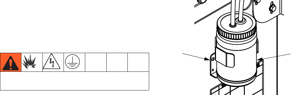
Advanced Display Module (ADM)
Replace Battery
A lithium battery maintains the ADM clock when power
is not connected.
To replace the battery:
1. Disconnect power to the ADM.
NOTE: This can be done by removing the CAN cable
from the bottom of the ADM.
2. Remove rear access panel.
3. Remove the old battery and replace with a new
CR2032 battery.
4. Properly dispose the old lithium battery according to
local codes.
5. Replace rear access panel.
6. Connect the power to the ADM and reset the clock
through Advanced Screen 1. Refer to Appendix B
- ADM Setup Screens Overview for more detail.
Install Upgrade Token
To install software upgrades:
1. Use software token 16H821. See Graco Control
Architecture™ Module Programming manual for
instructions.
NOTE: Upgrade all modules in the system to the
software version on the token, even if you are
replacing only one or two modules. Different soft-
ware versions may not be compatible.
All data in the module (System Settings, USB Logs,
Recipes, Maintenance Counters) may be reset to
factory default settings. Download all settings and
user preferences to a USB before the upgrade, for
ease of restoring them following the upgrade.
The latest software version for each system can be
found at www.graco.com.
Cleaning
Use any alcohol-based household cleaner, such as
glass cleaner, to clean the ADM. Spray on the rag then
wipe ADM. Do not directly spray the ADM.
ti12364a1

Maintenance
3A2175A 45
Motor Control Module (MCM)
Keep heat sink fins clean at all times. Clean them using
compressed air.
NOTE: Do not use conductive cleaning solvents on the
module.
Install Upgrade Token
NOTE: The MCM connection to the system is temporar-
ily disabled during the installation of upgrade tokens.
1. Use software token 16H821. See Graco Control
Architecture™ Module Programming manual for
instructions.
NOTE: Upgrade all modules in the system to the
software version on the token, even if you are
replacing only one or two modules. Different soft-
ware versions may not be compatible.
All data in the module (System Settings, USB Logs,
Recipes, Maintenance Counters) may be reset to
factory default settings. Download all settings and
user preferences to a USB before the upgrade, for
ease of restoring them following the upgrade.
The latest software version for each system can be
found at www.graco.com.
FIG. 14: Clean Heat Sink Fins
r_257396_3b9905_02b
Heat
Sink Fins
FIG. 15: Remove Access Cover
D
r_257396_3b9905_04b
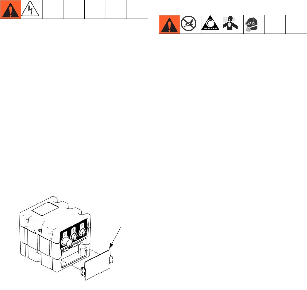
Maintenance
46 3A2175A
Fluid Control Module (FCM)
Install Upgrade and Key Tokens
NOTE: FCM connection to system is temporarily dis-
abled during the installation of upgrade or key tokens.
1. Use software token 16H821. See Graco Control
Architecture™ Module Programming manual for
instructions.
NOTE: Upgrade all modules in the system to the
software version on the token, even if you are
replacing only one or two modules. Different soft-
ware versions may not be compatible.
All data in the module (System Settings, USB Logs,
Recipes, Maintenance Counters) may be reset to
factory default settings. Download all settings and
user preferences to a USB before the upgrade, for
ease of restoring them following the upgrade.
The latest software version for each system can be
found at www.graco.com.
Fluid Inlet Strainer Screen
(Not included on HFRS systems)
The inlet strainers filter out particles that can plug the
pump inlet check valves. Inspect the screens daily as
part of the startup routine, and clean as required. The
standard strainer is 20 mesh.
Use clean chemicals and follow proper storage, transfer,
and operating procedures, to minimize contamination of
the A-side screen.
NOTE: Clean the A-side screen only during daily
startup. This minimizes moisture contamination by
immediately flushing out any isocyanate residue at the
start of dispensing operations.
1. Perform Pressure Relief Procedure on page 38.
2. Close the fluid inlet valve at the pump inlet and shut
off the appropriate feed pump. This prevents mate-
rial from being pumped while cleaning the screen.
3. Place a container under the strainer manifold (59d)
to catch fluid. Remove the strainer plug (59j).
4. Remove the screen (59g) from the strainer manifold.
Thoroughly flush the screen with compatible solvent
and shake it dry. Inspect the screen. If more than
25% of the mesh is blocked, replace the screen.
Inspect the gasket (59h) and replace as required.
5. Ensure the pipe plug (59k) is screwed into the
strainer plug (59j). Install the strainer plug with the
screen (59g) and gasket (59h) in place and tighten.
Do not overtighten. Let the gasket make the seal.
FIG. 16
ti12334a1
D
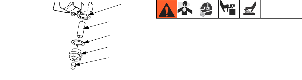
Maintenance
3A2175A 47
6. Open the fluid inlet valve, ensure that there are no
leaks, and wipe the equipment clean. Proceed with
operation.
IsoGuard Select™ System
(Not included on HFRS systems)
NOTE: The IsoGuard Select system is included on all HFRL
systems. It is available separately for HFRS systems as kit
24M154.
Check the condition of the A (Red) pump IsoGuard
Select fluid daily. Change the fluid if it becomes a gel, its
color darkens, or it becomes diluted with isocyanate.
Gel formation is due to moisture absorption by the pump
IsoGuard Select fluid. The interval between changes
depends on the environment in which the equipment is
operating. The pump lubrication system minimizes
exposure to moisture, but some contamination is still
possible.
Fluid discoloration is due to continual seepage of small
amounts of isocyanate past the pump packings during
operation. If the packings are operating properly, Iso-
Guard Select fluid replacement due to discoloration
should not be necessary more often than every 3 or 4
weeks.
To change pump IsoGuard Select fluid:
1. Perform Pressure Relief Procedure on page 38.
2. Remove fittings from IsoGuard Select fluid cylinder
inlet and outlet ports. Keep supply tube (ST), return
tube (RT), and leak management tube (LT) con-
nected to the fittings.
3. Carefully place ends of tubes with fittings still con-
nected into an empty pail to drain IsoGuard Select
fluid.
4. Lift the IsoGuard Select fluid reservoir (LR) out of
the bracket (RB) and remove the container from the
cap. Holding the cap over a suitable container,
remove the inlet check valve and allow the IsoGuard
Select fluid to drain. Reattach the check valve to the
inlet hose. See FIG. 18.
5. Drain the reservoir and flush it with clean IsoGuard
Select fluid.
6. When the reservoir is flushed clean, fill with fresh
IsoGuard Select fluid.
FIG. 17. Fluid Inlet Strainer
59g*
59h
59j
59k
ti9886a1
59d
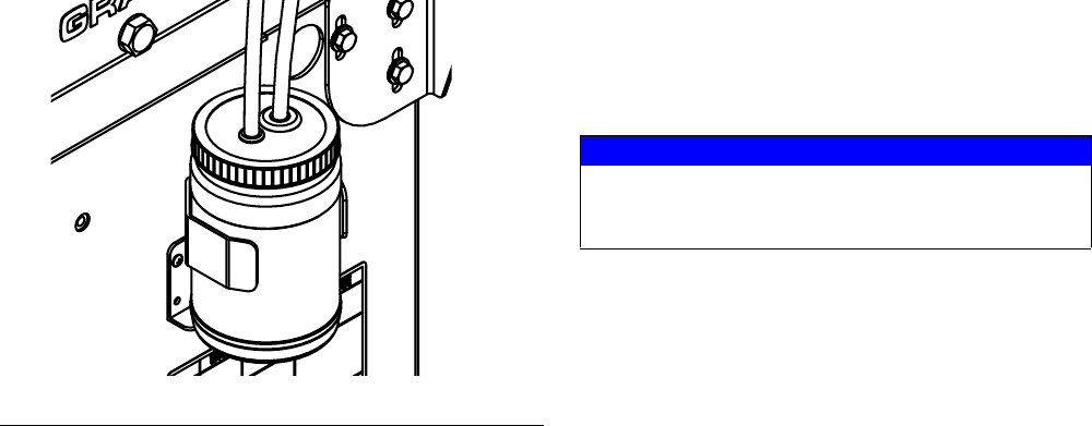
Maintenance
48 3A2175A
7. Thread the reservoir onto the cap assembly and
place it in the bracket (RB).
8. Push the supply tube (ST) approximately 1/3 of the
way into the reservoir.
9. Push the return tube (RT) into the reservoir until it
reaches the bottom.
NOTE: The return tube must reach the bottom of the
reservoir, to ensure that isocyanate crystals will settle to
the bottom and not be siphoned into the supply tube and
returned to the pump.
Prime IsoGuard Select Fluid Cylinder
Ensure that the IsoGuard Select fluid cylinder outlet
faces upward for air to exhaust.
1. Install IsoGuard Select fluid cylinder inlet fitting and
inlet tube into bottom of cylinder. The inlet tube is
the tube with a check valve installed in it which
points in the direction of flow towards the IsoGuard
Select fluid cylinder.
2. Install IsoGuard Select fluid cylinder outlet fitting
and outlet tube into top of cylinder. The outlet tube is
the tube with a check valve installed in it which
points in the direction of flow away from the Iso-
Guard Select fluid cylinder.
3. Remove check valve from end of outlet tube.
4. Use funnel to pour IsoGuard Select fluid into tube to
fill cylinder.
5. With check valve arrow pointing away from the Iso-
Guard Select fluid cylinder, install check valve in end
of outlet tube.
6. Install tubes into reservoir and install reservoir into
holder.
Clean Orifice Valves
Only for MD2 Valve using Orifice Block Kit 24E505 and
an orifice.
NOTE: 24E505 does not come with an orifice.
1. Follow Pressure Relief Procedure in MD2 valve
manual.
2. Use 5/16 in. nut driver to remove orifices.
3. Remove cap from orifice.
NOTE: The cap is held in place with reverse threads.
4. Remove needle from orifice. Thoroughly inspect all
o-rings and replace if necessary.
5. If necessary, use drill bit that is the same size as the
orifice to drill out the orifice. Orifice size is marked
on the orifice.
6. Liberally lubricate all o-rings.
7. Reassemble in reverse order. Torque orifices into
fluid housing to 20-30 in-lb (2.26-3.39 N•m).
FIG. 18: IsoGuard Select Fluid System
24C352_313998_8e
NOTICE
To prevent cross-contamination of the orifices, do not
interchange A component and B component parts.
The A component orifice is marked with an A.
Troubleshooting
3A2175A 49
Troubleshooting
Before performing any troubleshooting procedure:
1. Perform Pressure Relief Procedure on page 38.
2. Turn main power OFF.
3. Allow equipment to cool.
Try the recommended solutions in the order given for
each problem, to avoid unnecessary repairs. Also,
determine that all circuit breakers, switches, and con-
trols are properly set and wiring is correct before assum-
ing there is a problem.
Light Tower (Optional)
Errors include advisories, deviations, or alarms, so
green will only be on when none of these occur. A yellow
light can be on at the same time as red (flashing or solid
on) when an advisory exists at the same time as a devi-
ation or alarm.
Common Problems
Signal Description
Green on only System is powered up and there are
no error conditions present
Yellow on An advisory exists
Red flashing A deviation exists
Red on The system is shut down due to an
alarm occurring.
Problem Cause Solution
General
Display Module completely
dark
No Power Verify AC Power switch is ON
Thrown Breaker Check Machines Breakers and Reset
Loose Connection Tighten 5-pin cable on Advanced Display Module
Bad Display Module Replace Advanced Display Module
No or incorrect amount of
material dispensed from
either side
Ball Valve closed (if Installed) Open tank ball valve.
Tank Empty Add fluid
Tank Clogged Clean tank
Air In Material Prime the machine
Significant material leaking
from pump seal
Pump shaft worn and/or shaft seal
worn
Remove pump shaft assembly and reinstall read
pump rebuild kit
Material dispensed not cor-
rect weight
Specific gravity of one or more of the
two materials has changed since cali-
bration
Run calibration
Check valve malfunction Remove check valve; clean or replace as necessary
Piston worn or broken Replace Piston
Proportioning System
Proportioning pump does not
hold pressure when stalled
Pump piston or intake valve leaking 1. Observe gauges to determine which pump is los-
ing pressure.
2. Determine in which direction the pump has
stalled by observing which directional valve indi-
cator light is on.
3. Repair the valve.

Troubleshooting
50 3A2175A
Material imbalance. Inadequate flow from pump; cavitation Increase fluid supply to proportioning pump:
•Use 2:1 supply pump
•Use minimum 3/4 in. (19 mm) ID supply hose, as
short as practical
Fluid is too thick. Consult your material supplier for
the recommended fluid temperature to maintain a vis-
cosity of 250 to 1500 centipoise.
Clean inlet strainer screen
Worn pump inlet valve ball/seat or gasket
Pressure relief/circulation valve leak-
ing back to supply
Remove return line and determine if flow is present
while in SPRAY mode
Erratic pump movement Pump cavitation Feed pump pressure is too low. Adjust pressure to
maintain 100 psi (0.7 MPa, 7 bar) minimum.
Pump output low Obstructed fluid hose or gun; fluid
hose ID too small
Open, clear; use hose with larger ID
Worn piston valve or intake valve in
displacement pump
See pump manual 3A0019
Inadequate feed pump pressure Check feed pump pressure and adjust to 100 psi (0.7
MPa, 7 bar) minimum
Power Supply System
No power received from DC
power supply
Defective power supply Check circuit breaker. Check power supply. Replace
power supply.
No power to MCM, heat
zones, or tanks
Circuit breaker is tripping Check circuit breaker for tripping and defects. Diag-
nose cause of circuit breaker tripping before resetting
it. Replace defective parts if required.
Problem Cause Solution
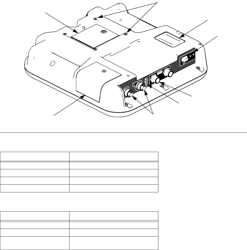
Troubleshooting
3A2175A 51
ADM Troubleshooting
ADM Module Status LEDs (CN) Conditions
USB Module Status LEDs (CL) Conditions
FIG. 19: ADM Component Identification - Rear
CR
CK
CJ
CL
CP
CN
CM
CS
ti12363a1
Module Status LED Signal Description
Green on System is powered up.
Yellow on Communication in progress.
Red solid ADM hardware failure.
Red flashing Uploading software.
Module Status LED Signal Description
Green flashing System is powered up.
Yellow on Downloading information to USB
Green/Yellow Flashing ADM is busy, USB cannot transfer
information when in this mode
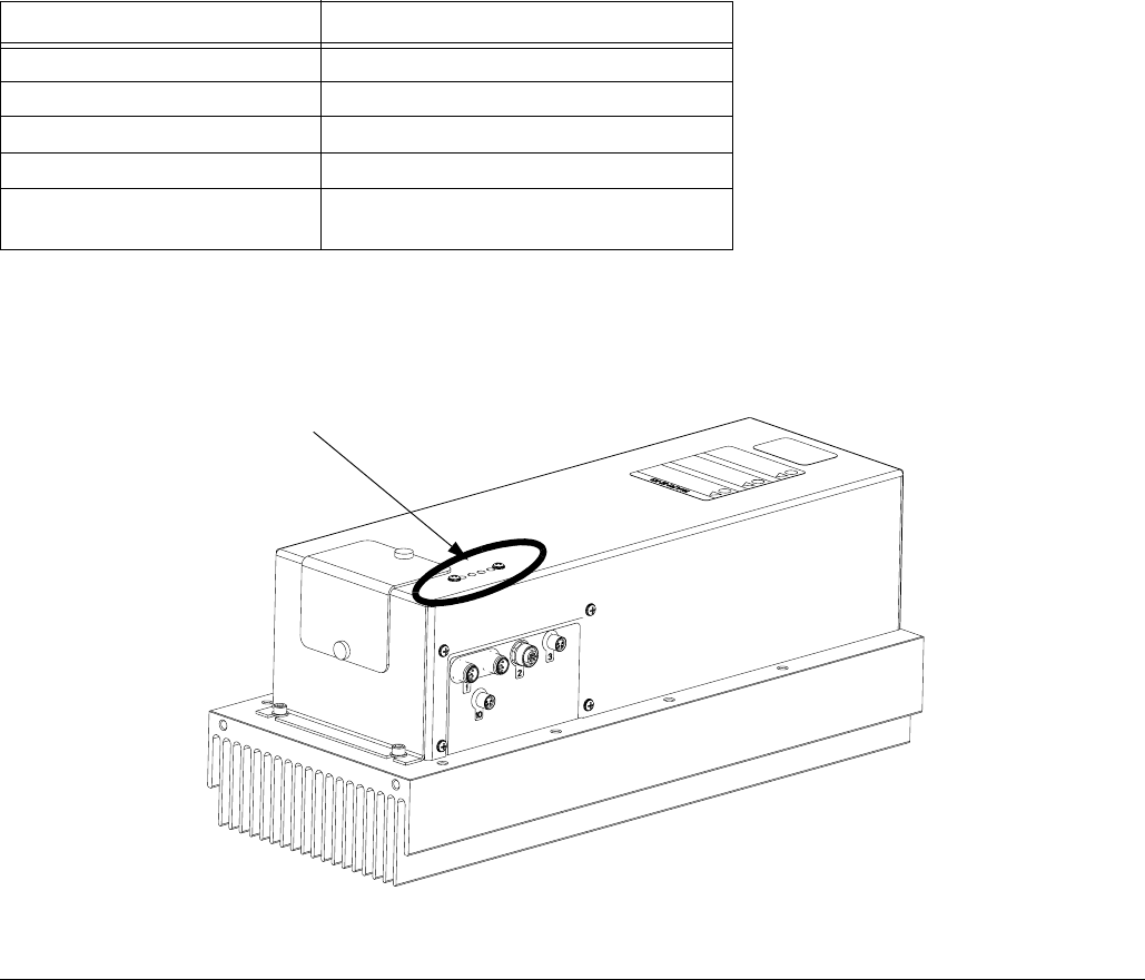
Troubleshooting
52 3A2175A
Motor Control Module
For MCM location, see reference MA in FIG. 4 on
page 19.
Diagnostic Information
7Table 3: LED Status Signal
Module Status LED Signal Description
Green on System is powered up.
Yellow on Internal communication in progress.
Red solid MCM hardware failure. Replace MCM.
Red flashing fast Uploading software.
Red flashing slow Token error. Remove token and upload
software token again.
FIG. 20: LED Signals
r_257396_3b9905_01b
LED
Signals
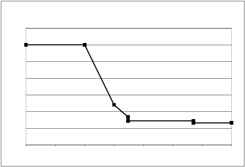
Troubleshooting
3A2175A 53
Acceptable Size and Duration of Power Line Voltage Fluctuations
The Motor Control Module is designed to withstand volt-
age fluctuations from the incoming power supply. If the
incoming power supply goes outside of the tolerable
range, an over-voltage condition is flagged and the sys-
tem shuts down in an alarm state. Excessive or
repeated over-voltage may permanently damage hard-
ware. The chart below shows the permissible magnitude
and duration of temporary over-voltage events. Consult
a qualified electrician if there are any concerns about
the available power supply.
Maximum Permissible Transient Voltage Surges
* Constructed from ITIC 1996 curve, referenced by IEC 61000-2-4
1200Vac, 1697Vdc
264Vac, 373Vdc
336Vac, 475Vdc
288Vac, 407Vdc
480Vac, 679Vdc
<--1 MW Max Surge Power
<--150 KW Max Surge Power
<--50 KW Max Surge Power <--No Power Limit
0
200
400
600
800
1000
1200
1400
Time (seconds)
Voltage (Volts RMS)
0.000001 0.00001 0.0001 0.001 0.01 0.1 1 10
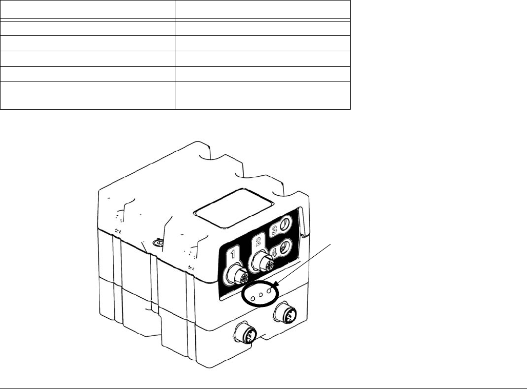
Troubleshooting
54 3A2175A
Fluid Control Module
Diagnostic Information
Module Status LED Signal Diagnosis
Green on System is powered up
Yellow Internal communication in progress
Red solid FCM hardware failure. Replace FCM.
Red flashing fast Uploading software
Red flashing slow Token error. Remove token and
upload software token again.
FIG. 21:
ti12337a1
Module Status LEDs

Advanced Display Module (ADM) Operation
3A2175A 55
Advanced Display Module (ADM) Operation
When main power is turned on by turning the main
power switch (MP) to the ON position, the splash screen
will be displayed until communication and initialization is
complete.
To begin using the ADM, the machine must be on and
enabled. To verify the machine is enabled, verify the
System Status Indicator Light (CB) is illuminated green,
see FIG. 7 on page 24. If the System Status Indicator
Light is not green, press the ADM Power On/Off (CA)
button . The System Status Indicator Light will illu-
minate yellow if the machine is disabled.
If the machine is in the Disabled mode screen press
repeatedly to select a different operating mode.
Perform the following tasks to fully setup your system.
1. Set general system settings. See Advanced
Screen 1, page 67.
2. Set units of measure. See Advanced Screen 2,
page 67.
3. Enable/disable system features. See Advanced
Screen 3, page 67.
4. Define control mode, dispense mode, and pump
information. See System Screen 1, page 61.
5. Define dispense valve and other system settings.
See System Screen 2, page 62.
6. Define labels and other system settings. See Sys-
tem Screen 3, page 63.
7. If L-Head is installed, define L-Head control
details. See Mix Head Operating Details Screen,
page 62.
8. Define level sensors and refill settings. See Supply
Screen, page 64.
9. If Night mode will be used, define Night mode set-
tings. See Conditioning Screen 3, page 66.
10. Calibrate machine. See Calibration Screen, Main,
page 60.
11. Define shots. See Shots Screen, page 59.
12. Define sequences. See Sequences Screen,
page 59.
13. If desired, view/reset counters. See Maintenance
Screen, page 64.
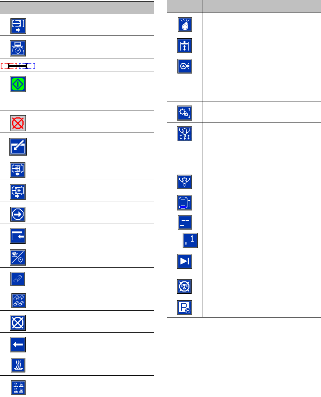
Appendix A - ADM Icons Overview
56 3A2175A
Appendix A - ADM Icons Overview
Icon Function
Access Learn Mode Calibration screen
Access Weight Calibration and Material
Specific Gravity Entry screen
Pump Graphic
Calibration Screen, Learn Mode:
Move pump
All other screens:
Begin Dispense
Stop Dispense
Press to enter the Conditioning Control
screen
Select left direction
Select right direction
Proceed to next step in calibration pro-
cedure
Back to main calibration screen
Run MCM Learn Mode
Erase Individual Data
Erase All Data
Abort Changing the Label
Backspace
Turn on or off the highlighted zone.
Turn on or off all zones.
Select mode
Move L-Head Cleanout Rod
With a mix head installed: Tur n s on
the mix head hydraulics and puts the
machine in low pressure circulation.
Press a second time to turn off insti-
gated system action.
Edit Operator Dispense Setting
Lock Dispense Valve Closed
(Press to lock the valved closed during
a dispense. Used to circulate through
the material manifold back to the tank
(the Pressure Relief/Dispense Valves
will need to be in the relief position).
Open, Close Valve
A (Red) and B (Blue) refill button
(Press to start/abort refill)
OR
Jump in to select sequence letter and
position.
Skip the next shot in selected
sequence. Only available when the sys-
tem is not dispensing.
Abort sequence and reset to first valid
position
Set system in park (icon will be selected
when system is parked)
Icon Function
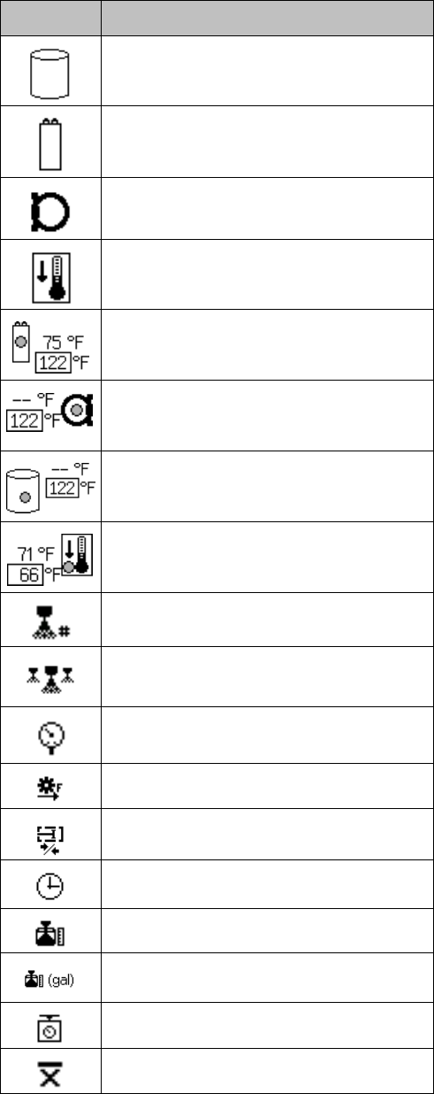
Appendix A - ADM Icons Overview
3A2175A 57
Tank Blanket Heater
Primary Heater
Heated Hose
Chiller
Current and setpoint temperature for
primary heater. Not displayed if heat
zone is not enabled.
Current and setpoint temperatures for
heated hose. Not displayed if heat zone
is not enabled.
Current and setpoint temperatures for
tank blanket. Not displayed if heat zone
is not enabled.
Current and setpoint temperatures for
chiller. Not displayed if heat zone is not
enabled.
Shot Number
Sequence Position
Pressure
Flow
Cycles
Time (Duration)
Volume
Amount of material moved through
pump (volume tracking)
Weight
Average weight for the calibration point
Icon Function
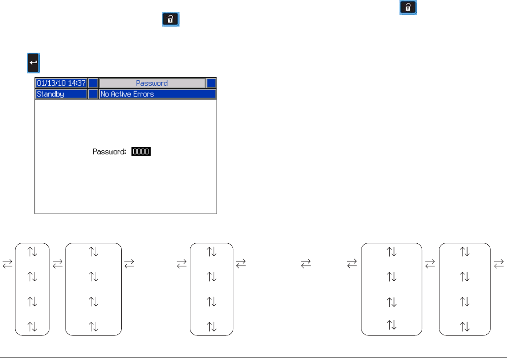
Appendix B - ADM Setup Screens Overview
58 3A2175A
Appendix B - ADM Setup Screens Overview
The ADM will start in the Run screens at the “Home”
screen. From the Run screens, press to access the
Setup screens. If the Setup screens password is turned
on, use the ADM keypad to enter the password then
press .
From the Setup screens, press to access the Run
screens. For Run screens information, see Appendix C
- ADM Run Screens Overview on page 68. FIG. 22
shows the flow of the Setup screens.
FIG. 22: Setup Screens Navigation Diagram
Calibration Maintenance
Shot #1
Shot #2
Shot #...
Sequences #1
Sequences #2
Sequences #...
Advanced #1
Advanced #2
Advanced #...
System #1
System #2
System #3
Supply Conditioning #1
Conditioning #2
Conditioning #3
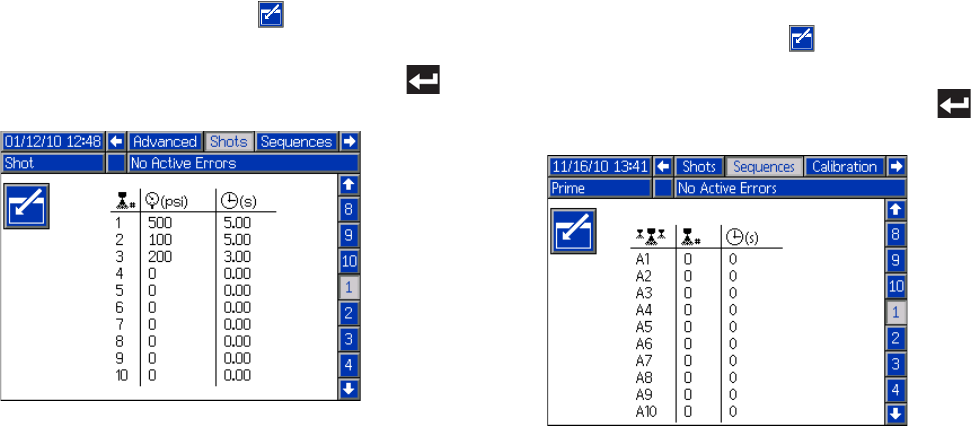
Appendix B - ADM Setup Screens Overview
3A2175A 59
Shots Screen
This screen allows the user to edit shot definitions. The
contents of this screen change based on the Dispense
and Control Mode selections. Shots may be defined by
pressure or flow rate depending upon the Control Mode
selection and by time (duration), volume, or weight
depending upon the Dispense Mode selection. See Sys-
tem Screen #1 for Control and Dispense Mode options.
See Home Screen, Shot Mode on page 69 for informa-
tion on how to use predefined shots.
NOTE: 100 shot definition are available across ten
pages.
To edit a shot definition:
1. Press the Enter screen button then use the
arrow keys to navigate to the desired value.
2. Type the new value then press the Enter button
to accept the new value.
Sequences Screen
This screen allows the user to edit sequence informa-
tion. The contents of this screen change based on the
Dispense and Control Mode selections.
Dispense detail is shown as volume, time, or weight
depending on which Dispense Mode is selected. See
System Screen 1 on page 61 for Dispense Mode
options. See Home Screen, Sequence Mode on
page 70 for information on how to use predefined
sequences.
NOTE: 5 sequences with 20 positions each are avail-
able across 10 pages.
To edit a sequence:
1. Press the Enter screen button then use the
arrow keys to navigate to the desired value.
2. Type the new value then press the Enter button
to accept the new value.
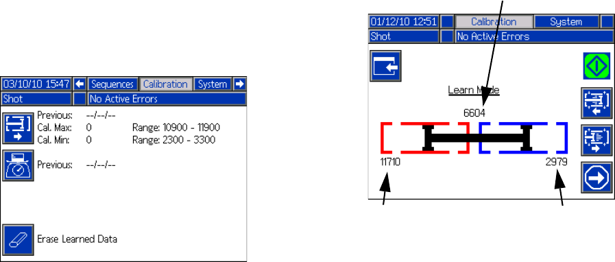
Appendix B - ADM Setup Screens Overview
60 3A2175A
Calibration Screen, Main
This screen shows calibration information for the system
and provides access to other calibration screens. See
Calibrate HFR on page 36 for how to use the calibration
screens to calibrate the machine.
The date next to each key represents the last time that
calibration was performed.
The “Cal. Min” and “Cal. Max” values are the system
recognized extreme ends of piston travel. See Calibra-
tion Screen, Learn Mode.
Calibration Screen, Learn Mode
This screen allows the user to calibrate piston position.
The piston can be moved to the left and right to obtain
the full range of motion. See Calibrate HFR on page 36
for how to use this screen to calibrate the machine.
Previously saved left
position
Previously saved right
position
Current position
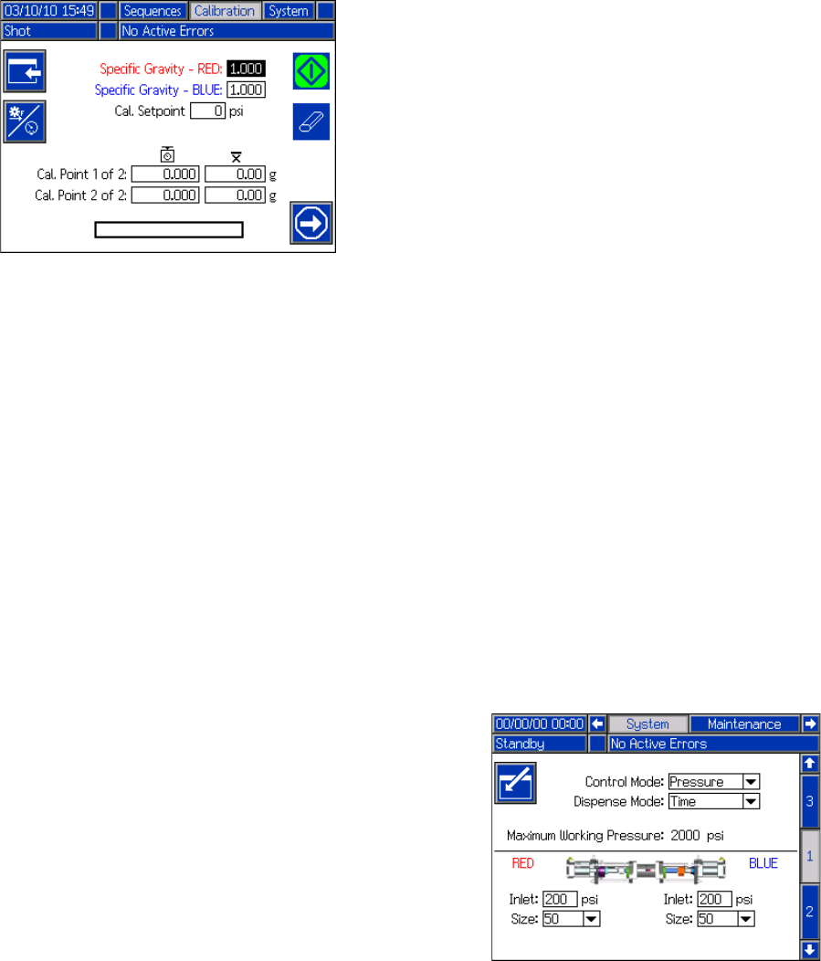
Appendix B - ADM Setup Screens Overview
3A2175A 61
Calibration Screen, Specific Gravity
This screen allows the user to enter material specific
gravities and perform weight calibration shots. See Cali-
brate HFR on page 36 for how and when to use this
screen to calibrate the machine.
System Screen 1
This screen allows the user to set important system set-
tings. Control Mode can be set to Pressure or Flow. With
Control Mode set to Pressure, the machine will adjust
dispense flow rate in order to maintain the requested
pressure. With Control Mode set to Flow, the machine
will dispense at a continuous flow rate regardless of
pressure fluctuations unless pressure alarm conditions
occur.
Dispense Mode can be set to Time, Volume, or Weight.
Dispense Mode controls how displayed amounts are
measured. If Dispense Mode is set to Weight, then the
machine dispenses until the desired weight of material
is dispensed. See Calibrate HFR on page 36 for more
information.
Pump sizes and inlet pressures must be entered on this
screen.
If pump sizes and inlet pressures are not entered prop-
erly, system performance will be affected. The inlet pres-
sure must be set to the maximum feed pressure that will
be seen by that side of the machine.
The maximum working pressure for the machine is dis-
played on this screen. The maximum working pressure
is dependent on the installed hoses and dispense valve.
The maximum working pressure is set to the lowest
rated system component. If 2000 psi hoses are installed
and the maximum working pressure displayed is not
2000 psi, see manual 313998 for instructions to set the
maximum working pressure for hoses. If the installed
dispense valve rating is below the maximum working
pressure shown here, verify the correct dispense valve
is selected on System Screen 2.
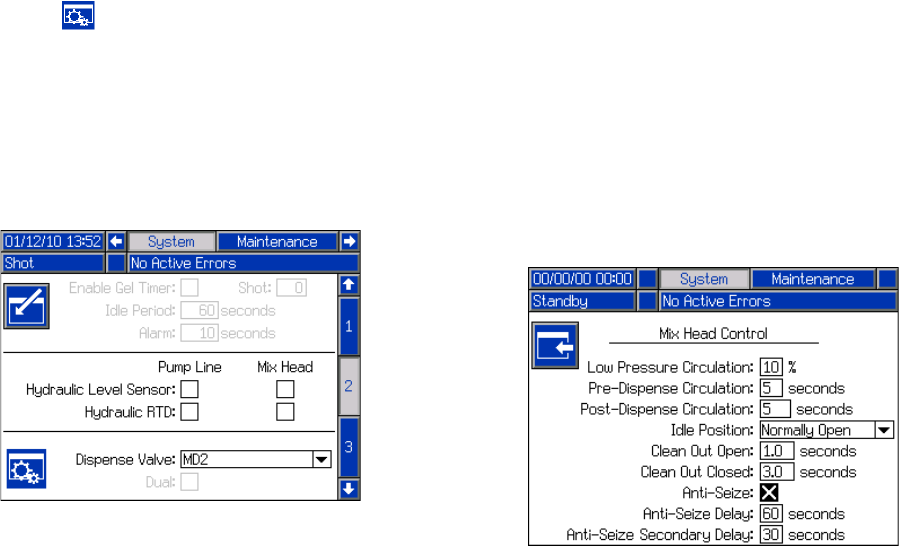
Appendix B - ADM Setup Screens Overview
62 3A2175A
System Screen 2
This screen allows the user to set the Gel Timer proper-
ties and set which items are installed on the machine.
When enabling the Gel Timer, the user must select one
of the 100 available shot definitions to use as the Gel
Shot. This shot will be dispensed when the Idle Period
expires. The Idle Period will begin after a dispense is
completed. Any dispense operation in the middle of the
timer countdown will reset the Idle Period counter. The
system will generate an audible alarm based upon the
user Alarm setting. The alarm will sound the
user-entered number of seconds before the Idle Period
expires.
The hydraulic level sensor and hydraulic RTD for both
the pump line and mix head must be marked as enabled
when installed in the system. If the sensors are not
marked as enabled, they will be ignored by the machine
controls.
Select the dispense valve installed in the system. This
selection is critical to ensure proper operation of the
machine. When a mix head is selected, the Dispense
Valve Details button will become active. When
active, pressing this button will open a screen used to
define the mix head operating parameters. See the Mix
Head Operating Details Screen on page 62.
Selecting the dispense valve will limit the system maxi-
mum working pressure to the maximum working pres-
sure of the dispense valve. See System Screen 1 on
page 61.
Mix Head Operating Details Screen
This screen allows the user to define the mix head oper-
ating parameters.
•Low Pressure Circulation: The percentage of set-
point at which the system will run during low pres-
sure circulation.
•Pre-Dispense Circulation: The time for which the
system will circulate at high pressure prior to dis-
pensing when the dispense command is triggered
while the system is in low pressure circulation.
•Post-Dispense Circulation: The time duration that
the system will remain in high pressure circulation
after a dispense before dropping into low pressure
circulation.
•Idle Position: Applies to an L-Head only. The posi-
tion of the cleanout rod when the mix head is idle.
•Clean Out Open: Applies to an L-Head only. The
amount of time the cleanout rod will remain open
immediately after the completion of a dispense.
•Clean Out Closed: Applies to an L-Head in a Nor-
mally Open configuration only. The amount of time
the cleanout rod will remain closed when it closes
after the completion of a dispense (after the clean
out open time delay).
•Anti-Seize Delay: Applies to an L-Head in a Nor-
mally Closed configuration only. After a shot occurs
and the cleanout piston closes, the first anti-seize
delay will count down then the cleanout piston will
open and close to break loose from any curing
material. The second anti-seize timer will then begin
counting down and the cleanout piston will open and
close again to break loose from any remaining cur-
ing material. If a shot occurs before both anti-seize
timers elapse, the anti-seize timers restart.
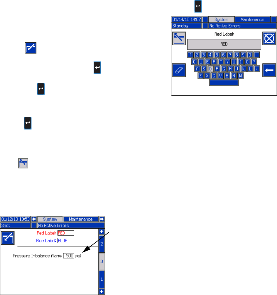
Appendix B - ADM Setup Screens Overview
3A2175A 63
System Screen 3
This screen allows the user to edit the labels for the A
(Red) and B (Blue) sides of the machine. The labels set
for the A (Red) and B (Blue) sides of the machine are
displayed throughout the screens. Labels are limited to
five characters.
To edit a label:
1. Press .
2. To edit the A (Red) label, press .
To edit the B (Blue) label, press the down arrow
then press . The keyboard will appear on the
screen. See Keyboard Screen on page 63.
3. Use arrow keys to select the desired letter and
press to accept the letter. To erase all text, press
the Eraser softkey. To go back one letter, press the
Back Arrow softkey.
4. When finished entering the new label, press
the button twice.
The pressure imbalance setting may be set from this
screen. Pressure imbalance is the allowable difference
in pressure between the two materials before an alarm
is triggered. The input range is 250-2000 psi (2-14 MPa,
17-138 bar).
Keyboard Screen
This screen is used to edit the A (Red) and B (Blue)
labels on the ADM. Use arrow keys to select the desired
letter and press to accept the letter.
Pressure
Imbalance
Setting
Appendix B - ADM Setup Screens Overview
64 3A2175A
Maintenance Screen
This screen shows shot number and sequence position
counters. Press the Enter Screen button and navigate to
the drop down box. Press the enter key and scroll to a
range of counters to view. Press the enter key again to
select the range of counters and display them on the
screen.
Counters may be erased individually. Navigate to the
counter you want to erase and press the Erase Individ-
ual button. Alternatively, each counter displayed on the
page may be erased simultaneously by pressing the
Erase All button.
Supply Screen
This screen allows the user to specify the operating
parameters for off-board, integrated tanks and indicate
which positions have level sensors installed. See the
Tank Feed Systems manual for information about install-
ing level sensors, see Related Manuals on page 3. The
user may select from the following refill settings: Dis-
abled, Monitor, Manual, Auto Top-Off, Auto Full-Volume.
NOTE: Use the “Disabled” setting if off-board tanks are
not installed.
The following describes system operation when each
tank mode is selected.
•Disabled
• Disables tank operation
•Monitor
• The top sensor generates a high level deviation
and the bottom sensor generates a low level
alarm
• Refill is not supported, no button is provided on
the run screens to initiate refill
• Errors will clear when the corresponding condi-
tion clears
•Manual
• The low level sensor will generate a low level
alarm
• A button is provided to the user on the run
screens to instigate a manual refill operation at
any time
• Manual refill will run until either the high level
sensor sees material, the user aborts the refill
via the refill button on the run screens, or the
refill time-out expires
• The low level alarm will clear when the condition
clears
•Auto Top-Off
• The low level sensor will generate a low level
alarm
• When the high level sensor does not see mate-
rial, automatic refill will begin and continue until
either the high level sensor sees material or
until the refill time-out expires
• The low level alarm will clear when the condition
clears
• A button is provided to the user on the run
screens to instigate an automatic refill operation
at any time, this button can also be used to
abort a refill operation
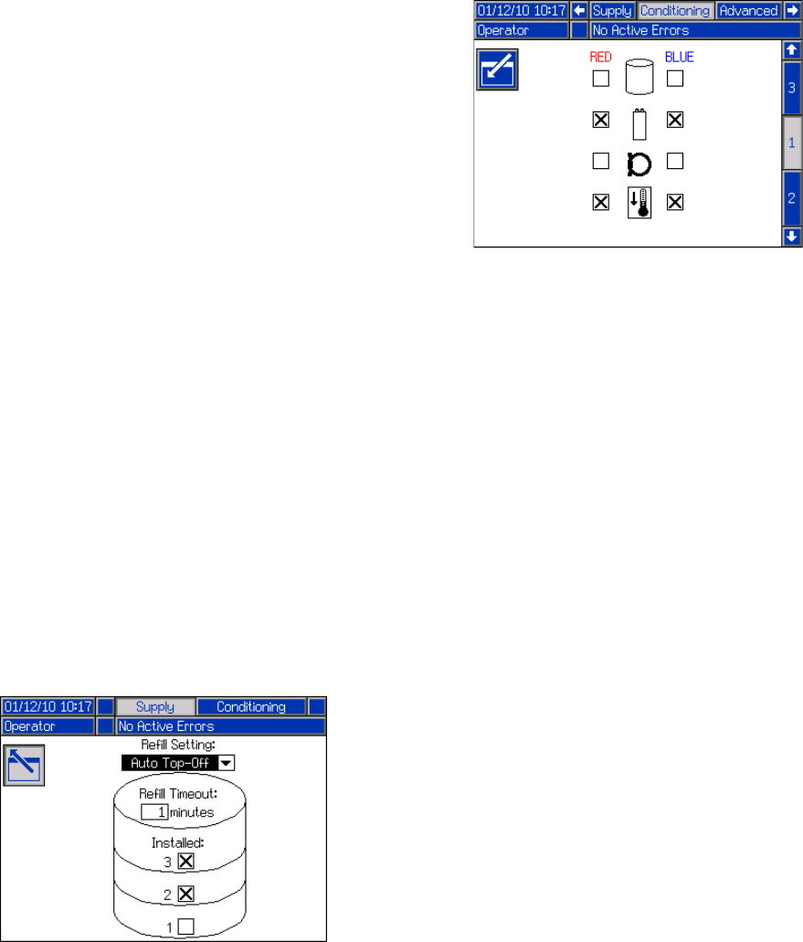
Appendix B - ADM Setup Screens Overview
3A2175A 65
•Auto Full-Volume
• The low level sensor will initiate an automatic
refill when it does not see material
• Automatic refill will continue until either the high
level sensor sees material or until the refill
time-out expires
• The low level alarm will clear when the condition
clears
• A button is provided to the user on the run
screens to instigate an automatic refill operation
at any time, this button can also be used to
abort a refill operation
If a refill setting other than Disabled is selected, the user
must set at least two level sensor locations as installed
by checking the check box on the screen. If all three
locations are set to installed, the system will default to
the Auto-Top Off refill setting and operate as follows:
• The low level sensor will generate a low level alarm.
• The high level sensor will generate a high level devi-
ation and abort any automatic refill operation.
• When the middle sensor is not satisfied, automatic
refill will begin and will run until either the middle
sensor is satisfied, the high level sensor generates a
deviation (if the middle sensor fails), or the refill
time-out expires.
• The low level alarm and the high level deviation will
clear when the condition clears.
• A button is provided to the user on the Run screens
to instigate an automatic refill operation at any time.
This button can also be used to abort a refill opera-
tion.
The refill time-out setting may be set by the user as a
means to abort the refill in the case of a high level sen-
sor failure. When an automatic refill begins, the time-out
counter will begin to count down. If the timer expires
before the high level sensor is satisfied, the refill will
abort.
Conditioning Screen 1
This screen allows the user to select which temperature
conditioning components are installed in the system.
Check the box next to the component type for the appro-
priate side of the system to indicate that a component is
installed. A maximum of four components may be
selected.
Appendix B - ADM Setup Screens Overview
66 3A2175A
Conditioning Screen 2
This screen shows the fluid path for the temperature
conditioning components and temperature setpoints for
each component.
NOTE: If tank blanket heaters or inline heaters are
installed along with hose heat, the hose heat setting will
be limited to at or below the inline or tank heat setting.
To edit the temperature setpoint and alarms for a partic-
ular component:
1. Press the Enter Screen button and navigate to the
component you wish to edit.
2. Press the enter key to display the setpoint and
alarm values associated with that component.
3. Edit the setpoint and alarm values and then press
the page back button to return to the previous
screen.
Conditioning Screen 3
This screen allows the user to configure Night Mode
operation. In Night Mode, the system will cycle on and
off periodically. Press the Enter Screen button and
adjust the on and off durations as desired.
When the system is in Night Mode and in an “On” cycle,
the system will circulate in low pressure. The installed
conditioning zones will be on and controlling to their
respective setpoints. When the system is in Night Mode
and in an “Off” cycle, the system will be idle. The system
will not be circulating, and the conditioning zones will not
be actively controlling temperature. When in Night
Mode, supply tanks will not fill.
NOTE: Gray fields on this screen are items unavailable
at this time. Future product releases will incorporate
these features.
N
OTE: All components are shown installed for refer-
e
nce only. Only 4 components can be installed at one
t
ime.
Appendix B - ADM Setup Screens Overview
3A2175A 67
Advanced Screen 1
This screen allows the user to set the language, date
format, current date, time, setup screens password,
screen saver delay, and turn on or off silent mode.
Advanced Screen 2
This screen allows the user to set the units of measure.
Advanced Screen 3
This screen allows the user to control the availability of a
few key system features.
•Disable Dispensing: Check this box to disable dis-
pensing from the ADM. A footswitch, gun trigger, or
other external signal will be the only means with
which to trigger a dispense.
•Disable Modifying Temp Setpoint: Check this box
to disable modifying temperature setpoints from the
Status run screen.
•Disable Operator Mode Adjustments: When this
box is checked, the user will not be able to adjust
the dispense setpoint in Operator Mode.
•Low Heater Temp Disables Dispense: When this
box is checked, the system will reject dispense
requests on system power up until all enabled heat
zones have reached their setpoint.
•High Chiller Temp Disables Dispense: When this
box is checked, the system will disable dispensing
on system power up until all enabled chiller zones
have reached their setpoint.
•Operator Mode Cavitation Alarm: Check this box
to enable cavitation alarms in Operator Mode. Clear
this box to disable cavitation alarms in Operator
Mode.
•Enable Downloading of USB Logs: When this box
is checked, USB logs will be automatically down-
loaded when a USB drive is inserted into the ADM.
•Complete Dispense with Setpoint Error: When
this box is checked, the shot will continue dispens-
ing even if the system never reaches the desired
setpoint.
The screen displays the date of the last USB log down-
load. When downloading logs, only data recorded since
the displayed date will be downloaded. To reset the date
and force a download of the USB logs in their entirety,
press the Erase Single button next to the Date of Last
Download label. The next time a USB drive is inserted
into the ADM, the complete USB logs will be down-
loaded. See Appendix F - USB Operation on page 85
for a complete explanation.
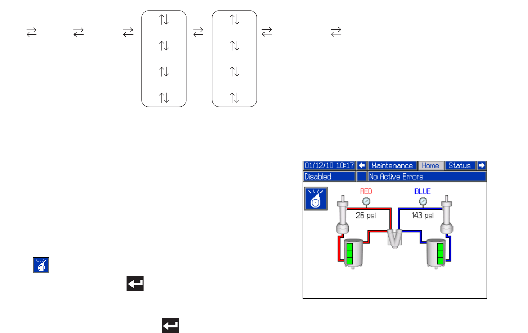
Appendix C - ADM Run Screens Overview
68 3A2175A
Appendix C - ADM Run Screens Overview
Run screens are divided into five major sections: status,
errors, events, and maintenance. The following diagram
demonstrates the flow of the Run screens beginning
with the Home screen.
Home Screen
The Home screen is the first screen that displays in the
Run screens. It shows the current fluid pressure on the
A (Red) and B (Blue) fluid outlets of the pump and if
there are any active errors. If tanks are installed in the
system, the fill level is shown on each tank.
To select an operating mode, press the Select Mode
button repeatedly until the desired mode is shown
then press the Enter button to select the mode.
Alternately, press the Select Mode button and use the
up and down arrow keys until the desired mode is
shown, then press the Enter button to select the
mode. The available operating modes are operator,
sequence, shot, standby, night, and disabled.
FIG. 23: Run Screens Navigation Diagram
Maintenance
Home Status Events #1
Events #2
Events #...
Errors #1
Errors #2
Errors #...
* Supply tanks shown for reference only. Your sys-
tem may not include supply tanks.
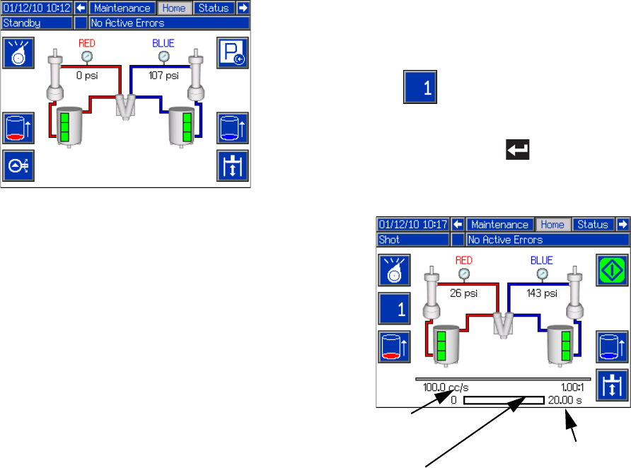
Appendix C - ADM Run Screens Overview
3A2175A 69
Home Screen, Standby Mode
In Standby Mode, the user can enable heating, park the
pumps, refill the tanks, circulate materials.
Home Screen, Shot Mode
This mode allows the user to select one of 100 pre-
defined shot numbers. See Shots Screen on page 59
for information about editing shot definitions.
To use a predefined shot:
1. Enter shot mode.
2. Press and use the numeric keypad to enter
the desired shot number.
3. Press the Enter button to select the shot num-
ber.
4. Press the dispense button to begin dispensing.
Target
Flow/Pressure
Ratio
Target dispense amount (time/vol-
ume/weight depending on Dis-
pense Mode)
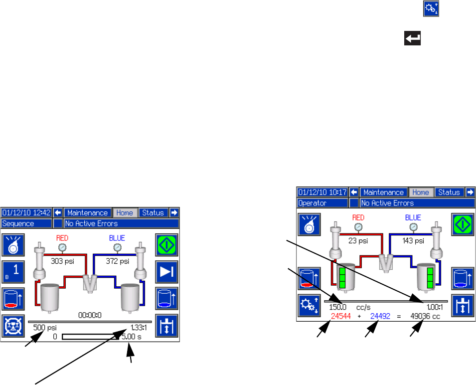
Appendix C - ADM Run Screens Overview
70 3A2175A
Home Screen, Sequence Mode
This mode allows the user to select one of five
sequences (A-E). The progress bar on the bottom of the
screen shows the progress of a shot dispensing from
the selected sequence. See Sequences Screen on
page 59 for information about editing sequence defini-
tions.
To use a predefined sequence:
1. Ensure that the machine is in Sequence Mode.
2. Press the sequence letter/position selection button.
3. Use the left and right arrows to toggle between letter
and position selection. When selecting a sequence
letter (A-E), use the up and down arrow keys to
scroll through the available letters. When selecting a
sequence position, type in the desired position with
the numeric keypad. The system will reject invalid
letter/position selections.
4. Press the enter key to accept the sequence let-
ter/position.
5. Press the Dispense button to begin dispensing.
Home Screen, Operator Mode
This mode allows users to set a pressure or flow rate to
dispense material without using predefined shot infor-
mation. Pressure or flow rate availability is dependent
on the Control Mode selection, see System Screen 2
on page 62.
To edit the pressure or flow rate, press the button.
The value to change will now be highlighted. Type the
new value then press the Enter button to accept it.
The machine will begin dispensing at the set pressure or
flow rate when the dispense button is pressed and will
stop dispensing when it is pressed again. If a foot switch
is installed, the machine will dispense and continue to
dispense until the foot switch is released. If the foot
switch is used with a Mix Head installed a foot switch
press will start the pre-dispense timer and dispense
material when the timer expires. Another foot switch
press will terminate the dispense and start the post dis-
pense timer.
Ta r g e t
Flow/Pressure
Ratio
Target dispense amount (time/vol-
ume/weight depending on Dis-
pense Mode)
Total of resetta-
ble material
counters
B (Blue) reset-
table material
counter
A (Red) resetta-
ble material
counter
Operator
Setting
Ratio
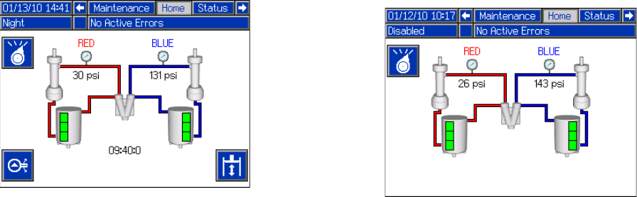
Appendix C - ADM Run Screens Overview
3A2175A 71
Home Screen, Night Mode
In Night Mode, the system will cycle on and off
periodically. The recirculation on/off cycle begins
automatically upon entering Night Mode. See
Conditioning Screen 3 on page 66.
Home Screen, Disabled Mode
When this mode is selected, the machine will not be
able to dispense or condition (heat/cool) material. The
setup screens cannot be accessed while in Disabled
mode. Use the Select mode button to exit Disabled
mode.
Appendix C - ADM Run Screens Overview
72 3A2175A
Status Screen
The status screen provides all of the operational func-
tionality of the Home screen except for operating mode
selection. Refer to the Home screen and operating
mode descriptions for information on this functionality.
In addition to the functionality provided by the Home
screen, the Status screen also provides material condi-
tioning information and control.
Status Screen, Conditioning Control
This screen allows users to turn on and off heat zones
individually or all at once. The grey circles indicate that a
zone is off and green circles indicate that a zone is on.
When a zone is on it is actively controlling temperature.
To turn a single zone on/off:
1. Press to enter the Conditioning Control screen.
2. Use the arrows keys to navigate to the desired zone.
3. Press to turn the selected zone on. When a
zone is on, the button will be selected. Press the
button again to turn the zone off.
To turn all zones on/off:
1. Press to enter the Conditioning Control screen.
2. Press the to turn on all zones. When all zones
are on, the button will be selected. Press the button
again to turn all zones off.
All zones shown for reference. Only four zones may
be active at one time.
Appendix C - ADM Run Screens Overview
3A2175A 73
Errors Screens
This screen shows users a list of errors that have
occurred in the system. Each error entry includes a
description and error code along with a date and time
stamp. There are 5 pages, each holding 10 errors. The
50 most recent errors are shown.
Refer to the Troubleshooting section on page 49 for a
detailed description of all of the system errors.
Events Screens
This screen shows users a list of events that have
occurred in the system. Each event includes a descrip-
tion and event code along with a date and time stamp.
There are 20 pages, each holding 10 events. The 200
most recent events are shown.
Refer to the Troubleshooting section on page 49 for a
detailed description of all of the system events.
Maintenance Screen 1
This screen displays historical information for each
pump in the system. The Batch counters are resettable
and count both material usage and pump cycles. The
Total counters are not resettable by the user. They also
count both material usage and pump cycles. For mate-
rial usage counters, units are displayed next to the vol-
ume/weight indicator icons.
To erase a batch counter, press the Enter Screen button
and navigate to the field to be erased. Press the Erase
Single button to erase that data point. Alternatively, the
Erase All button may be pressed to erase all of the batch
data points simultaneously.
NOTE: In a circulation system, the pumpline must be
stopped to erase counters.

Appendix D - ADM Error Codes
74 3A2175A
Appendix D - ADM Error Codes
Error
Code Error Name Error Description
Error
Type Cause Solution
A4H3
Mix Head
Motor
Overload
Refer to AC Power Pack manual
DEH3 Soft Stop
Asserted
MBH3
Low Mix
Head Oil
Level
P1H3
Low
Accumulator
Pressure
P4H3
High
Accumulator
Pressure
T4H3
High Mix
Head Oil
Temp.
WDF3 M1 Material
Rod Shift Fail
WDD3 M1 Cleanout
Rod Shift Fail
0500
Invalid
Weight Cal.
Data
The three point calibration data
is invalid, system will operate
in weight mode but will attempt
to volumetrically calculate
weight. This will lead to
consistent shots which will be
offset for the desired dispense
amount.
Deviation Invalid data Re-calibrate the machine
05A1 Invalid Auto
Cal. Data
The system will ignore the
calibration data gathered and
will use information gathered
during dispenses
Deviation Invalid data
If any messages appeared indicating why the
calibration failed attempt to fix the problem then
re-run the calibration
A4A6 Red Blanket
Overcurrent
An over current was detected
on the output
Alarm
Bad heaters Measure resistance of heater
A4B5 Blue Blanket
Overcurrent Alarm
A4A3 Red Inline
Overcurrent Alarm
A4B1 Blue Inline
Overcurrent Alarm
A4A2 Red Hose
Overcurrent Alarm
A4B4 Blue Hose
Overcurrent Alarm
A4A7 Red Chiller
Overcurrent Alarm High voltage Measure voltage across the disconnect switch.
Voltage should measure between 190 and 264 Vac.
A4B8 Blue Chiller
Overcurrent Alarm Shorted Temperature
Control Module
If temperature rises for a zone that has been disabled,
replace Temperature Control Module
A4H1 Motor Over
Current
High current has been
detected on a phase and has
been shutdown to prevent
damage
Alarm
Bad internal wiring of the
motor Replace motor
Short circuit of motor
wiring
Check wiring to the motor to ensure no bare wires are
touching and that no wires are shorted to ground
A4M1 Motor Over
Current
Too much current is being
drawn from the wall Alarm Low voltage from the wall
during load
Make sure the supply line is properly sized for the
load and is above the minimum voltage requirements

Appendix D - ADM Error Codes
3A2175A 75
A4N1 Motor Over
Current
A hardware current fault has
occurred causing a system
shutdown
Alarm
Short circuit of motor
wiring
Check wiring to the motor to ensure no bare wires are
touching and that no wires are shorted to ground
Motor rotor has become
locked
Unplug the directional valve (so pressure will not
build) and try to move the motor again. If this
succeeds then the power pack may need to be
replaced. If the motor is still unable to move, the
bearings or hydraulic pump have likely failed in the
motor and will need to be replaced.
A7A6 Red Blanket
Control Fault
Unexpected current to
heater/chiller
Alarm
Shorted Temperature
Control Module
If temperature rises for a zone that has been disabled,
replace Temperature Control Module
A7B5 Blue Blanket
Control Fault Alarm
A7A3 Red Inline
Control Fault Alarm
A7B1 Blue Inline
Control Fault Alarm
A7A2 Red Hose
Control Fault Alarm
A7B4 Blue Hose
Control Fault Alarm
A7A7 Red Chiller
Control Fault Alarm
A7B8 Blue Chiller
Control Fault Alarm
A8A6
No Red
Blanket
Current
No current to the conditioning
zone
Alarm
Tripped circuit breaker Visually check circuit breaker for a tripped condition
A8B5
No Blue
Blanket
Current
Alarm
A8A3 No Red Inline
Current Alarm
A8B1 No Blue Inline
Current Alarm
A8A2 No Red Hose
Current Alarm
A8B4 No Blue Hose
Current Alarm Low power
Measure voltage across input terminals on power line
filter. Voltage should measure between 190 and 264
Vac
A8B7
No Red
Chiller
Current
Alarm Cable unplugged/loose
power Check for loose or disconnected wires or plugs
A8B8
No Blue
Chiller
Current
Alarm Bad heater(s) Measure resistance of heater(s)
A9C1 Motor Over
Current
A software error has occurred
commanding too much current Alarm Bad Motor Control
Module code
Check for MCM software update, load latest MCM
software, if problem persists contact Graco
B9C0 Small Shot
Request
The requested dispense
amount is below the minimum
amount of the system (25% of
the combined pump volumes is
the minimum)
Deviation
Pumps are defined with
the wrong size
On the ADM go into the Setup screens to the System
screens then make sure that the pump sizes are
defined correctly
Requested shot is below
the capabilities of the
current pump setup
If the user has to be able to take the shot the system
must be fitted with smaller pumps
Error
Code Error Name Error Description
Error
Type Cause Solution

Appendix D - ADM Error Codes
76 3A2175A
CAC1 Comm. Error
Motor
Communication error
Alarm
Loose/broken connection Check connection
CAC3 Comm. Error
Red Tank Alarm
CAC4 Comm. Error
Blue Tank Alarm
CAC5 Comm. Error
Mix Head Alarm
CAC6 Comm. Error
Mix Head 2 Alarm
CAC7 Comm. Error
Ratio Monitor Alarm
CAA6 Comm. Error
Red Blanket Alarm
CAB5 Comm. Error
Blue Blanket Alarm
CAA3 Comm. Error
Red Inline Alarm
CAB1 Comm. Error
Blue Inline Alarm
CAA2 Comm. Error
Red Hose Alarm
CAB4 Comm. Error
Blue Hose Alarm Module not programmed Program the module
CAA7 Comm. Error
Red Chiller Alarm Module missing power Check power supply connection
CAB8 Comm. Error
Blue Chiller Alarm Module bad Replace module
D1A1 Setpoint Not
Reached
The set point was not reached
and the pump was shutdown Deviation Material restriction too
high for requested flow Reduce flow request
D2A1 Setpoint Not
Reached The set point was not reached Deviation
Pump cannot reach the
requested pressure Increase restriction in the system
Pump cannot reach the
requested flow Decrease restriction in the system
D3A1 Setpoint
Exceeded The set point was exceeded Deviation
System underwent a
change that caused a
large drop in restriction
(such as new orifices)
Erase learned System Data, found in the setup
screens under calibration
No material in pumps Make sure the material lines are open and have
proper feed pressure
D5A1 Invalid Learn
Mode Data
This calibration lets the MCM
know where the ends of the
pump are. If the data gathered
during this process is outside
of normal parameters the
machine will operate with a
greatly reduced stroke.
Deviation
Recalibrate the machine Rerun the learn mode calibration
Loose/bad connection Check to ensure the pressure transducer is properly
installed and all wires are properly connected
Bad linear position
sensor
Verify pump moves to limits, if problem persists
replace linear position sensor
D6A1 Position
Sensor Fault
The linear position sensor is
returning data that should not
be possible during normal
operation
Alarm
Loose/bad connection to
linear position sensor
Check to ensure the linear position sensor is properly
installed and all wires are properly connected
Bad linear position
sensor Replace linear position sensor
Linear position sensor
may be loose where
attached to pump
housing
Re-tighten the sensor and re-calibrate the machine
DDA1 Red Pump
Cavitation
Cavitation was detected on the
given pump
Deviation Insufficient material
being supplied or
insufficient material
pressure on feed system
Verify that incoming ball valves are open
DDB2 Blue Pump
Cavitation
Deviation Verify that feed pumps are supplying material
Debris or packout in the
incoming fluid filter
Inspect filter for debris of filler packout and clean or
replace as necessary
Error
Code Error Name Error Description
Error
Type Cause Solution

Appendix D - ADM Error Codes
3A2175A 77
DFA1 Pump Not
Parked
The pump failed to reach the
park position Deviation
Orifices blocked Clear blockage
Hose blocked Clear or replace hose as necessary
Dispense valve failed to
open
Check to make sure the dispense valve is properly
configured and connected to the MCM
DSC0 Pumps Not
Defined
The type or size of the Red or
Blue material pumps have not
been defined
Alarm Properly setup the
system
On the ADM go into the setup screens -> System->
then make sure that the pump type and size are set
(not --)
F7D1 Pump Failed
to Stall
When the pump tried to stall to
pressure the pump traveled
more than it should in normal
operation (only applies to
dead-headed system)
Deviation
Failure of the dispense
valve
Ensure the valve has a proper air supply and seals
properly. If not, service the valve as necessary.
Material leak
Visually inspect the machine and hoses for sign of
leakage. NOTE: This error will display after 2 full
piston strokes so the leak will be substantial.
Out of material Fill tanks
L111 Red Low
Material Level
Low material level in tanks
Deviation Tanks low on material Fill tanks with material
L122 Blue Low
Material Level
Deviation Loose/broken connection
If the tanks appear to have plenty of material check to
make sure the level sensor is connected to the proper
port and that the cord is not damaged
Bad level sensor Replace level sensor
L311 Red High
Material Level High material level in tanks
Deviation
Defective fill valve
If the tanks appear to have plenty of material check to
make sure the level sensor is connected to the proper
port and that the cord is not damaged
L322 Blue High
Material Level Deviation
L6A1 Red Auto
Refill Timeout The tank stand has been filing
for a time greater than
expected
Deviation No material is actually
being fed Make sure the feed pumps are operating properly
L6B2 Blue Auto
Refill Timeout Deviation
Loose level sensor
connection Check for loose or disconnected wires or plugs
Bad level sensor Replace level sensor
MBH1 Low Oil Level
The volume of oil in the tank is
below the minimum level
needed for the system to
properly operate
Alarm
Low oil level Check oil level and if low add more hydraulic fluid
Loose/bad connection
Check to ensure the hydraulic oil level sensor is
properly connected to the MCM and that the wire has
not been damaged
Bad level sensor Replace sensor
Leak in hydraulic driver
Inspect hydraulic driver end seals and early leak
detection tubing. Replace seals as necessary and
replace lost oil.
Leak in the hydraulic
reservoir, heat
exchanger
Inspect the hydraulic reservoir fittings and filter for
leaks. Repair or replace as necessary and replace
lost oil.
MBN1 Low Motor
Performance
The motor magnetism has
decreased to the point where
performance is greatly reduced
Advisory Prolonged exposure to
heat or high voltage
If error persists and performance can no longer
satisfy the user requirements the motor will need to
be replaced
Error
Code Error Name Error Description
Error
Type Cause Solution

Appendix D - ADM Error Codes
78 3A2175A
N4A1 Pump Failed
to Move
The MCM attempted to move
the pump but no movement
was detected
Deviation
Motor failure Visually check to ensure the pump is moving, if not
ensure the motor is wired properly
Hydraulic power pack
failure
If motor is moving but pump is not and pressure is not
building they hydraulic power pack may need
servicing
Loose/bad connection to
the linear position sensor
Check to ensure the linear position sensor is properly
connected to the MCM and the wiring has not be
damaged
Failure of the linear
position sensor Replace the linear position sensor
Motor no longer coupled
to hydraulic pump
Reset coupler per specifications and retighten set
screws
Supply tube from
hydraulic pump to
manifold is loose or
broken
Retighten or replace supply tube
Broken motor shaft Replace motor
Over-pressure valve
dumping to tank
Verify that no outside forces are stopping the pump
from moving, then inspect over-pressure valve for
damage or debris
P400
Thermal
Pressure
Rise
Pressure has risen to an
unsafe level due to thermal
expansion of materials. All
conditioning zones have
automatically been turned off.
Deviation High pressure Open the dispense valve manually or open the valves
to bleed pressure
P4A1 Red Pressure
Shutdown
The material pump pressure
exceeded the maximum
operating pressure as defined
in the setup screens
Alarm Dispense valve failed to
open
Check to make sure the dispense valve is properly
configured and connected to the MCM
P4B2
Blue
Pressure
Shutdown
Alarm
Bad dispense valve Replace dispense valve
Restriction in the
material lines Check to ensure there is no blockage
Invalid maximum
pressure defined
Make sure the requested pressure is within the max
operating pressure, which can be found on the setup
screen System 1
Orifices blocked Clear blockage
Hose blocked Clear blockage or replace hose as necessary
Dispense valve failed to
open
Check to make sure the dispense valve is properly
configured and connected to the MCM
P4D0 Pressure
Imbalance
The pressure difference
between the Red and Blue
material is greater than the
defined amount
Alarm
Dispense line is clogged Ensure the material flow is equally restricted on both
material lines
Pressure imbalance is
defined too low
On the ADM go into the setup screens -> System->
and ensure the pressure imbalance value is the
maximum acceptable to prevent unnecessary alarms
which will abort dispenses
Orifice blocks closed off
too much on one or both
sides
Verify that one or both of the orifice blocks dispense
when adjusted to the fully open position then adjust
accordingly
Debris in the orifice block Relieve system pressure then remove the orifice from
the orifice block and inspect for debris in the cavity
Material fillers may have
packed out in an orifice
Relieve system pressure and remove the orifice from
the orifice block and inspect for pack out. Clean or
replace as necessary.
Out of material Fill tanks with material
Feed system defective Replace defective item
P6A1 Red Pressure
Sensor Fault The pressure sensor is
providing invalid/no pressure
readings
Alarm Loose/bad connection Check to ensure the pressure transducer is properly
installed and all wires are properly connected
P6B2
Blue
Pressure
Sensor Fault
Alarm
Bad sensor Replace pressure transducer
No material in pump Fill tanks
Error
Code Error Name Error Description
Error
Type Cause Solution

Appendix D - ADM Error Codes
3A2175A 79
T1A6
Red Tank
Low Fluid
Temp.
Fluid temperature is below the
defined low alarm limit
Alarm
Tripped circuit breaker Visually check circuit breaker for a tripped condition
T1B5
Blue Tank
Low Fluid
Temp.
Alarm
T1A3
Red Inline
Low Fluid
Temp.
Alarm
T1B1
Blue Inline
Low Fluid
Temp.
Alarm
T1A2
Red Hose
Low Fluid
Temp.
Alarm
T1B4
Blue Hose
Low Fluid
Temp.
Alarm Low power
Measure voltage across input terminals on power line
filter. Voltage should measure between 190 and 264
Vac
T1A7
Red Chiller
Low Fluid
Temp.
Alarm Cable unplugged/loose
power Check for loose or disconnected wires or plugs
T1B8
Blue Chiller
Low Fluid
Temp.
Alarm Bad heater(s) Measure resistance of heater(s)
T3H1 Oil Temp.
Cutback
The hydraulic oil temperature
is approaching a level where
damage is possible so the
Motor Control Module is
limiting the output to a safe
level
Deviation
No power to fan Check cord to make sure fan has power
Debris is fan or fan grill Clear debris from fan/fan grill
Low air volume from fan
Try to stop fan by lightly pressing on the center with a
pencil eraser. If the fan slows down easily it will need
to be replaced
T3N1 Motor Temp.
Cutback
Motor temperature is
approaching a level where
damage is possible so the
motor control module is limiting
the output to a safe level
Advisory
No power to fan Check cord to make sure fan has power
Debris is fan or fan grill clear debris from fan/fan grill
Low air volume from fan
Try to stop fan by lightly pressing on the center with a
pencil eraser. If the fan slows down easily it will need
to be replaced
Ambient environmental
conditions are too hot Move machine to an area below 120°F
Motor/pump coupler may
be rubbing on hydraulic
pump
Reset coupler per specifications and retighten set
screws
T4B5
Blue Tank
High Fluid
Temp.
Fluid temperature is above the
defined high alarm limit
Alarm
Defective RTD Replace RTD
T4A3
Red Inline
High Fluid
Temp.
Alarm
T4B1
Blue Inline
High Fluid
Temp.
Alarm
T4A2
Red Hose
High Fluid
Temp.
Alarm
T4B4
Blue Hose
High Fluid
Temp.
Alarm
T4A7
Red Chiller
High Fluid
Temp.
Alarm
Defective High Power
Temperature Control
Module
Replace High Power Temperature Control Module
T4B8
Blue Chiller
High Fluid
Temp.
Alarm Loose connections Tighten connections
Error
Code Error Name Error Description
Error
Type Cause Solution

Appendix D - ADM Error Codes
80 3A2175A
T4C1 Motor Control
High Temp.
The temperature the MCM has
reached a level where product
life will be decreased
drastically and has been
shutdown for protection
Alarm
No power to fan Check cord to make sure fan has power
Debris is fan or heatsink Clear debris from fan or heatsink
Low air volume from fan
Try to stop fan by lightly pressing on the center with a
pencil eraser. If the fan slows down easily it will need
to be replaced
Motor may be damaged Replace motor
Debris is packed in the
MCM’s heat sink fins Clear debris from MCM heat sink fins
T4H1 Oil Temp.
Shutdown
The hydraulic oil is at a
temperature where
performance is impacted
significantly and has resulted
in a system shutdown
Alarm
No Power to Fan Check cord to make sure fan has power
Debris in fan or fan grill Clear debris from fan/fan grill
Low air volume from fan
Try to stop fan by lightly pressing on the center with a
pencil eraser. If the fan slows down easily it will need
to be replaced
T4N1 Motor Temp.
Shutdown
Motor temperature is too high
and system has been
shutdown to prevent possible
damage
Alarm
No power to fan Check cord to make sure fan has power
Debris is fan or fan grill Clear debris from fan/fan grill
Low air volume from fan
Try to stop fan by lightly pressing on the center with a
pencil eraser. If the fan slows down easily it will need
to be replaced
Ambient environmental
conditions are too hot Move machine to an area below 120°F
Motor may be damaged Motor may need to be replaced
T6A6 Red Tank
RTD Fault
RTD 1 is giving no or invalid
data
Alarm
Loose or bad connection Check RTD wiring
T6B5 Blue Tank
RTD Fault Alarm
T6A3 Red Inline
RTD Fault Alarm
T6B1 Blue Inline
RTD Fault Alarm
T6A2 Red Hose
FTS Fault Alarm
T6B4 Blue Hose
FTS Fault Alarm
T6A7 Red Chiller
RTD Fault Alarm
T6B8 Blue Chiller
RTD Fault Alarm Bad RTD Replace RTD
T6C6 Red Blanket
RTD Fault
RTD 2 is giving no or invalid
data
Alarm
Loose or bad connection Check RTD wiringT6C5 Blue Blanket
RTD Fault Alarm
T6C7 Red Chiller
RTD Fault Alarm
T6C8 Blue Chiller
RTD Fault Alarm Bad RTD Replace RTD
T8A6 No Heat Red
Tank
No temperature rise
Alarm
Tripped circuit breaker Visually check circuit breaker for a tripped conditionT8B5 No Heat Blue
Tank Alarm
T8A3 No Heat Red
Inline Alarm
T8B1 No Heat Blue
Inline Alarm Low Power
Measure voltage across input terminals on power line
filter. Voltage should measure between 190 and 264
Vac
T8A2 No Heat Red
Hose Alarm Cable unplugged/loose
power Check for loose or disconnected wires or plugs
T8B4 No Heat Blue
Hose Alarm Bad heater(s) Measure resistance of heater(s)
Error
Code Error Name Error Description
Error
Type Cause Solution

Appendix D - ADM Error Codes
3A2175A 81
T8A7 No Cooling
Red Chiller
No temperature decline
Alarm Tripped circuit breaker Visually check circuit breaker for a tripped condition
T8B8 No Cooling
Blue Chiller Alarm
Defective cooling valve
Disconnect the valve and measure the voltage across
the wires when the chiller is running to ensure 24V is
being delivered to the valve. If so, the cooling valve
will likely need replacing.
Chilled water supply off Turn on chilled water supply
Loose or bad connection Check RTD wiring
T9A6 Red Blanket
Temp. Cutoff
Heater overtemperature cutoff
Alarm
Defective RTD Replace RTD
T9B5 Blue Blanket
Temp. Cutoff Alarm
T9A3 Red Inline
Temp. Cutoff Alarm
Defective High Power
Temperature Control
Module
Replace High Power Temperature Control Module
T9B1 Blue Inline
Temp. Cutoff Alarm Loose connections Tighten connections
T9C6
Red Blanket
Ctrl
Shutdown
PCB over temperature
Alarm
Overheated
Temperature Control
Module
Turn conditioning zone off. Wait a few minutes. If the
condition does not clear or regenerates consistently,
replace heater module
T9C5
Blue Blanket
Ctrl
Shutdown
Alarm
T9C3
Red Inline
Ctrl
Shutdown
Alarm
T9C1
Blue Inline
Ctrl
Shutdown
Alarm
T9C2 Red Hose Ctrl
Shutdown Alarm
T9C4
Blue Hose
Ctrl
Shutdown
Alarm
T9C7
Red Chiller
Ctrl
Shutdown
Alarm
T9C8
Blue Chiller
Ctrl
Shutdown
Alarm
V1H1 Motor Control
Undervoltage
The voltage to the MCM has
dropped to a level where
performance is greatly affected
Alarm
Tripped circuit breaker Visually check circuit breaker for a tripped condition
Supply lines providing
low voltage
Check incoming voltage to ensure it is above the
minimum operating voltage
V4A6 Red Blanket
Overvoltage
High line voltage
Alarm
Incoming line voltage is
too high
Measure voltage across disconnect switch. Voltage
should measure between 190 and 264 Vac.
V4B5 Blue Blanket
Overvoltage Alarm
V4A3 Red Inline
Overvoltage Alarm
V4B1 Blue Inline
Overvoltage Alarm
V4A2 Red Hose
Overvoltage Alarm
V4B4 Blue Hose
Overvoltage Alarm
V4A7 Red Chiller
Overvoltage Alarm
V4B8 Blue Chiller
Overvoltage Alarm
Error
Code Error Name Error Description
Error
Type Cause Solution

Appendix D - ADM Error Codes
82 3A2175A
V4H0 Motor Control
Overvoltage
The voltage to the MCM has
reached an unsafe level and
has been shutdown in an
attempt to prevent damage
Alarm Supply lines providing
high voltage
Check incoming voltage to ensure it is below the
maximum operating voltage
W0U0 USB Update
Failed
The ADM tried to upload a
system settings file but failed Alarm
System Settings file is
corrupt
Replace the system settings file with a backup or new
file
System Settings file is
intended for another
system
Ensure that the first line in the settings.txt file contains
the text GMS. If not replace the file with the proper
system update file.
WBH1 Motor
Encoder Fault
An error has been detected on
the motor position sensor Alarm
Failing sensors If error persists the motor will need to be replaced
Loose connection Ensure the d-sub connector to the motor is connected
and the wiring is intact
WKH1 High Motor
Speed
The motor has reached a
speed that should not be
reached in normal operation
and was shutdown to prevent
possible damage
Alarm
No power to directional
valve Make sure the directional valve has power
Bad directional valve
connection
Make sure the cord to the directional valve is
connected to the correct port and the cord is not
damaged
Directional valve failure The directional valve will need to be replaced
Hydraulic power pack
failure The hydraulic power pack will need repair
Defective encoder Replace encoder
Motor no longer coupled
to hydraulic pump
Reset coupler per specifications and retighten set
screws
Supply tube from
hydraulic pump to
manifold is loose or
broken
Retighten or replace supply tube
Broken motor shaft Replace motor
WM06 Red Tank
Con. Fault
High current to relay 1
Alarm
Broken contactor Replace contactor
WM05 Blue Tank
Con. Fault Alarm
WM03 Red Inline
Con. Fault Alarm
WM01 Blue Inline
Con. Fault Alarm
WM02 Red Hose
Con. Fault Alarm
WM04 Blue Hose
Con. Fault Alarm
WM07 Red Chiller
Con. Fault Alarm
WM08 Blue Chiller
Con. Fault Alarm
WMA6 Red Blanket
High Temp.
Tank blanket is above the
defined high alarm limit
Alarm Defective RTD Replace RTD
WMB5 Blue Blanket
High Temp. Alarm
Defective High Power
Temperature Control
Module
Replace High Power Temperature Control Module
Loose connections Tighten connections
Error
Code Error Name Error Description
Error
Type Cause Solution

Appendix D - ADM Error Codes
3A2175A 83
WMC6 Red Tank
Con. Fault
Unexpected current to relay 1
Alarm
Shorted module If temperature is being affected by a zone that has
been disabled, replace heat module
WMC5 Blue Tank
Con. Fault Alarm
WMC3 Red Inline
Con. Fault Alarm
WMC1 Blue Inline
Con. Fault Alarm
WMC2 Red Hose
Con. Fault Alarm
WMC4 Blue Hose
Con. Fault Alarm
WMC7 Red Chiller
Con. Fault Alarm
WMC8 Blue Chiller
Con. Fault Alarm
WMH1
Motor
Controller
Fault
A general fault has occurred
within the MCM Deviation Internal hardware failure Cycle power, if the error persists the MCM will need to
be replaced
WSC0
Invalid
Setpoint
Request
The requested controlling
value (pressure or flow) is
outside the limits of the system
Deviation
System incorrectly setup
On the ADM go into the setup screens -> System->
and ensure that all pages have properly defined
values
Shot incorrectly defined Redefine shot with control parameters within the limits
of the system
WSD0
Invalid Gel
Timer
Definition
The shot that was entered for
the gel timer is not a valid shot.
This must be fixed before the
gel timer will function properly
Deviation
Gel timer shot is below
the minimum dispense
amount or set for a
invalid pressure/flow
Select a different shot or modify existing shot data
The MCM has
determined that the gel
timer shot will not be able
to be executed based
parameters entered in
the ADM
If you are certain that the shot is within parameters,
try running the Learn Mode routine found in the setup
screen Calibration. If the error persists, a gel shot with
reduced control parameters is required.
Error
Code Error Name Error Description
Error
Type Cause Solution

Appendix E - System Events
84 3A2175A
Appendix E - System Events
Event Code and
String Triggers
REL00: System Pow-
ered On
The System was powered on.
REM00: System Pow-
ered Off
The System was powered off.
REB00: Stop Button
Pressed
The Red stop button was pressed on
the Advanced Display Module.
RECH0: Learn Mode
Executed
A learn mode calibration was success-
fully completed.
RENN0: Automatic
Cal. Performed
The system was successfully charac-
terized with the Automatic calibration.
RECA1: Red Mate-
rial SG Modified
The Red materials specific gravity was
modified.
RECB2: Blue Material
SG Modified
The Blue materials specific gravity was
modified.
RENC1: Cal. Point 1
Weight Entered
A value for the first point in the three
point calibration was entered.
RENC2: Cal. Point 2
Weight Entered
A value for the second point in the
three point calibration was entered.
RENC4: Cal. Point 1
Weight Erased
The running average for point one of
the three point calibration was erased.
RENC5: Cal. Point 2
Weight Erased
The running average for point two of
the three point calibration was erased.
REND0: Ratio Check
Dispense
A ratio check shot was dispensed from
the ratio check calibration screen.
REA00: Disp.
Occurred (Shot #)
A dispense has occurred of the given
shot number.
REH00: Gel Timer
Dispense
The gel timer expired and the system
automatically took the gel shot.
RER01: Shot Count
Reset
A counter from the shot counters main-
tenance page was erased
RER02: Seq. Posi-
tion Count Reset
A counter from the sequence counters
maintenance page was erased
RERA1: Red Mate-
rial Volume Reset
The resettable totalizer for the Red
material volume was reset to zero.
RERB1: Blue Material
Volume Reset
The resettable totalizer for the Blue
material volume was reset to zero.
RERA2: Red Mate-
rial Weight Reset
The resettable totalizer for the Red
material weight was reset to zero.
RERB2: Blue Material
Weight Reset
The resettable totalizer for the Blue
material weight was reset to zero.
RERA3: Red Cycle
Count Reset
The resettable cycle counter for the
Red pump was reset to zero.
RERB3: Blue Cycle
Count Reset
The resettable cycle counter for the
Blue pump was reset to zero.
REQU1: Settings
Downloaded
The system settings were successfully
transferred from the ADM to a USB
drive.
REQU2: Settings
Uploaded
The system settings file was success-
fully transferred from the USB drive to
the ADM.
REQU3: Language
Downloaded
The custom language file was suc-
cessfully transferred from the ADM to a
USB drive.
REQU4: Language
Uploaded
The custom language file was suc-
cessfully transferred from the USB
drive to the ADM.
REQU5: Logs Down-
loaded
The Error/Event and Shot data logs
were successfully transferred from the
ADM to a USB drive.
REAR0: Night Mode
Recirc On
While in night mode the system has
automatically entered a low recircula-
tion mode and attempted to turn on all
enabled conditioning zones.
REBR0: Night Mode
Recirc Off
While in night mode the system has
automatically stopped the low recircu-
lation mode and turned off all condi-
tioning zones.
Event Code and
String Triggers
Appendix F - USB Operation
3A2175A 85
Appendix F - USB Operation
Overview
There are 3 main uses for the USB on a GMS system
• Ability to download a log of the past 50,000 errors
and events and a shot log that can contain over
250,000 snapshots of critical dispense information
• Ability to download, modify, and upload custom lan-
guage files
• Ability to download and upload system configura-
tions
• This data includes most user selectable and
user configurable settings.
• This data does not include pump counters, error
and event logs, shot and sequence counters
USB Options
The only options for USB on the ADM are in Advanced
Screen 2, see page 67.
The first option is a checkbox that enables or disables
the downloading of the Error Event and Shot Data log
files. The Shot Data log runs during all recirculation,
shots, and operator modes.
The second option is the Erase icon which will reset the
last download date to a time where all logs can be
downloaded, 10/01/09. This will allow the user to down-
load all the USB log entries, which may take over 2
hours if the log files are full. Currently the ADM does not
monitor the USB logs and alert the user when data may
be overwritten so in order to minimize download times
and the risk of losing data it is recommended that the
user download the logs every 2 weeks or more often if
the machine is used during more than one full shift a
day.
Download Log Files
If the “Enable Downloading of USB Logs” is checked,
the user can use a USB stick-drive to download the log
files.
To download the log files, insert a high-quality USB
stick-drive into the USB port in the bottom of the ADM.
The ADM will automatically begin downloading the log
files as well as the custom language file (DISP-
TEXT.TXT) and the system settings (SETTINGS.TXT).
The status of the download will be shown in the Status
bar.
Appendix F - USB Operation
86 3A2175A
Log Files, Folder Structure
Each time a stick-drive is inserted into the ADM USB
port, a new folder named DATAxxxx is created. The
number at the end of the folder name is incremented
each time a stick-drive is inserted and data is down-
loaded or uploaded. In each DATAxxxx folder there is
two log files. They are formatted as .csv (comma sepa-
rated value) files and can be opened by most text editors
or data processing programs such as Excel.
FIG. 24: DOWNLOAD, DATAxxxx Folders
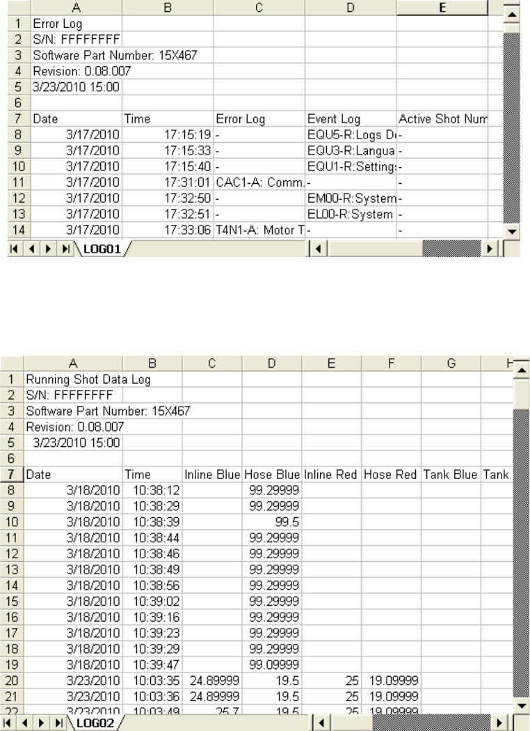
Appendix F - USB Operation
3A2175A 87
Example LOG01 File
The LOG01 file is the Errors and Events log file.
Example LOG02 File
The LOG02 file is the Shot Data Log file.
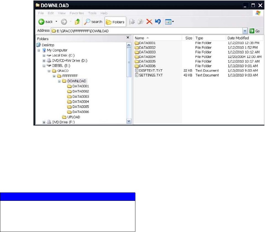
Appendix F - USB Operation
88 3A2175A
Transfer System Settings
Use the following process to transfer system settings
from one machine to another.
1. Insert a high-quality USB stick-drive into the USB
port on the system with the settings to be trans-
ferred. Once the download is complete the SET-
TINGS.TXT file will be located in the “DOWNLOAD”
folder.
2. Plug the USB stick-drive into a computer.
3. Navigate to the DOWNLOAD folder.
4. Copy the SETTINGS.TXT file from the DOWNLOAD
folder into the UPLOAD folder.
5. Remove the USB stick-drive from the computer and
install it into the ADM USB port for the second
machine. The software will automatically begin
updating.
NOTE: Before the update begins the ADM automatically
shuts down the system, aborting any in-progress dis-
pensing. When the software is updating the system a
pop-up box will appear to inform the user of the update
and the system will lock. Once the update is complete
the ADM will tell the user to cycle power to apply the
updates. Once this box appears it is safe to remove the
drive before cycling power.
6. When the software is done updating, remove the
USB stick-drive from the ADM USB port and install
in a computer.
7. Navigate to the UPLOAD folder and remove the
SETTINGS.TXT file.
NOTE: Immediately after uploading the settings, remove
the SETTINGS.TXT file from the UPLOAD folder to pre-
vent accidental loss of data the next time the USB
stick-drive is inserted into the ADM USB port. If there is
a SETTINGS.TXT file in the UPLOAD folder when the
USB stick-drive is inserted into the ADM USB port the
software will try to update the ADM.
NOTICE
The user should never attempt to modify the SET-
TINGS.TXT file in any way. Graco is not responsible
for damages caused by an improperly modified
setup file.
Appendix F - USB Operation
3A2175A 89
Update Custom Language
Use the following process to customize the text on the
ADM. The language file DISPTEXT.TXT can be modi-
fied in Excel but must be saved as a Unicode Text file
with the extension .TXT in order for it to properly import.
1. Insert a high-quality USB stick-drive into the USB
port on the system with the settings to be trans-
ferred. Once the download is complete the DISP-
TEXT.TXT file will be located in the “DOWNLOAD”
folder.
2. Plug the USB stick-drive into a computer.
3. Navigate to the DOWNLOAD folder.
4. Copy the DISPTEXT.TXT file from the DOWNLOAD
to your computer.
5. Use any data processing software such as Excel to
edit the DISPTEXT.TXT file. When done editing
save the file as the “Unicode Text” format. See
Example DISPTEXT.TXT File on page 90.
a. In the first column, locate the string to change.
b. In the second column of the same row, enter the
new string.
c. Save the file as a Unicode Text file. The name
must remain “DISPTEXT.TXT”.
6. Copy the edited DISPTEXT.TXT file into the
UPLOAD folder.
7. Remove the USB stick-drive from the computer and
install it into the ADM USB port. The software will
automatically begin updating.
NOTE: Before the update begins the ADM automatically
shuts down the system, aborting any in-progress dis-
pensing. When the software is updating the system a
pop-up box will appear to inform the user of the update
and the system will lock. Once the update is complete
the ADM will tell the user to cycle power to apply the
updates. Once this box appears it is safe to remove the
drive before cycling power.
8. When the software is done updating, remove the
USB stick-drive from the ADM USB port and install
in a computer.
9. Navigate to the UPLOAD folder and remove the
DISPTEXT.TXT file.
NOTE: Immediately following uploading the language
file, remove the DISPTEXT.TXT file from the UPLOAD
folder to prevent accidental loss of data the next time the
USB stick-drive is inserted into the ADM USB port. If
there is a DISPTEXT.TXT file in the UPLOAD folder
when the USB stick-drive is inserted into the ADM USB
port the software will try to update the ADM.
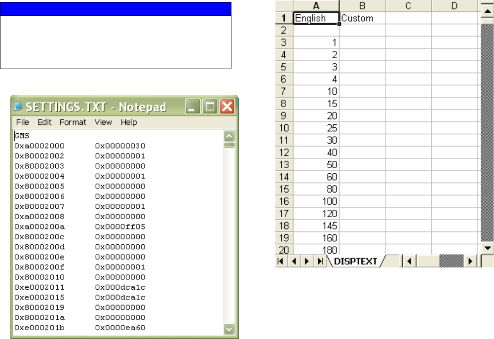
Appendix F - USB Operation
90 3A2175A
Example SETTINGS.TXT File Example DISPTEXT.TXT File
NOTICE
The user should never attempt to modify the SET-
TINGS.TXT file in any way. Graco is not responsible
for damages caused by an improperly modified
setup file.

Accessories
3A2175A 91
Accessories
HFR Discrete Gateway Module (DGM) Kits
Single DGM Kit, 24F843
Dual DGM Kit, 24F844
DGM only, 24G830
The HFR Discrete Gateway Module (DGM) allows the
user to control an HFR through an external control
device such as a PLC. The DGM operates in conjunc-
tion with the existing Advanced Display Module (ADM)
such that both devices can be used to control the
machine. See HFR Discrete Gateway Module manual
3A1149 for more information.
Secondary Supply Pump to Create a Tandem Unit
(HFRS Equipment Only)
Part No. Description
24M154 IsoGuard® Select Assembly with 32 oz reservoir
(Included on HFRL units)
24F516 IsoGuard® Select Fluid, 6 Quarts
255244 Footswitch with Guard and 4 meter cable
Part No.
Drum/Ram
Size
gallon (liter) Type Displacement Ratio
24M0028 5 (19) Carbon Steel
60 cc 20:1
24M0026 55 (208)
24M0029 5 (19) Stainless Steel
24M0027 55 (208)
Technical Data
92 3A2175A
Technical Data
All other brand names or marks are used for identification purposes and are trademarks of their respective owners.
Maximum Fluid Working Pressure . . . 3000 psi (21MPa, 207 bar)
See Models starting on page 4 for specific information
Maximum Fluid Temperature . . . . . . . 120°F (50°C)
Fluid Inlet Pressure at Inlet Fitting:
HFRL Models . . . . . . . . . . . . . . . . 50 psi (345 kPa, 3.4 bar) to 250 psi (1.8 MPa, 18 bar)
HFRS Models . . . . . . . . . . . . . . . . 250 psi (1.8 MPa, 18 bar) to 3000 psi (21 MPa, 207 bar)
HFRS (Regulated Pressure). . . . . 250 psi (1.8 MPa, 18 bar) to 1500 psi (10 MPa, 103 bar)
Fluid Inlets . . . . . . . . . . . . . . . . . . . . . Component A (Red): 3/4 npt(f)
Component B (Blue): 3/4 npt(f)
Fluid Outlets on Manifold . . . . . . . . . . Component A (Red): 1/2 in. npt(f)
Component B (Blue): 1/2 in. npt(f)
Air Inlet. . . . . . . . . . . . . . . . . . . . . . . . 1/4 NPS
Air Inlet Pressure . . . . . . . . . . . . . . . . 40 psi (280 kPa, 2.8 bar) to 100 psi (0.7 MPa, 7 bar)
Fluid Circulation Ports . . . . . . . . . . . . 1/4 npsm(m), with plastic tubing, 250 psi (1.8 MPa, 18 bar) maximum
Line Voltage Requirement . . . . . . . . . 230V / 1 phase: 195-264V, 50/60 Hz
400V / 3 phase: 360-440V, 50/60 Hz
Amperage Requirement. . . . . . . . . . . See Models on page 4
Sound Power . . . . . . . . . . . . . . . . . . . 93 dB
Hydraulic reservoir capacity. . . . . . . . 8 gal. (30 liters)
Recommended hydraulic fluid . . . . . . Citgo A/W Hydraulic Oil, ISO Grade 46
Weight . . . . . . . . . . . . . . . . . . . . . . . . 634 lb (288 kg) (Not including supply pumps)
Wetted Parts . . . . . . . . . . . . . . . . . . . Aluminum, stainless steel, zinc-plated carbon steel, brass, carbide, chrome,
fluoroelastomer, PTFE, ultra-high molecular weight polyethylene, chemically
resistant o-rings
Technical Data
3A2175A 93
Motor Control Module Technical Data
Overtemperature protection is provided to protect from motor overload.
Current limit, set via the software, is provided as a secondary protection from motor overload.
All installations and wiring must comply with NEC and local electrical codes.
Input Specifications
Input Line Voltage . . . . . . . . . . . . . . . . . . . . . . . . . . . 0-264 Vac, line-to-line
Input Line Phasing . . . . . . . . . . . . . . . . . . . . . . . . . . . Single or Three Phase
Input Line Frequency . . . . . . . . . . . . . . . . . . . . . . . . . 50/60 Hz
Input Current per Phase. . . . . . . . . . . . . . . . . . . . . . . 25A (three-phase), 50A (single-phase)
Maximum Branch Circuit Protection Rating: . . . . . . . 30A (three-phase), 63A (single-phase)
Short Circuit Current Rating. . . . . . . . . . . . . . . . . . . . 5 kA
Output Specifications
Output Line Voltage . . . . . . . . . . . . . . . . . . . . . . . . . . 0-264 Vac
Output Line Phasing . . . . . . . . . . . . . . . . . . . . . . . . . Three Phase
Output Current . . . . . . . . . . . . . . . . . . . . . . . . . . . . . . 0-30A
Output Overload. . . . . . . . . . . . . . . . . . . . . . . . . . . . . 200% for 0.2 seconds
DC Power Supply . . . . . . . . . . . . . . . . . . . . . . . . . . . . . . . 24 Vdc, Class 2, Graco-provided power supply
Enclosure . . . . . . . . . . . . . . . . . . . . . . . . . . . . . . . . . . . . . Type 1
Max Ambient Temperature . . . . . . . . . . . . . . . . . . . . . . . . 50°C (122°F)
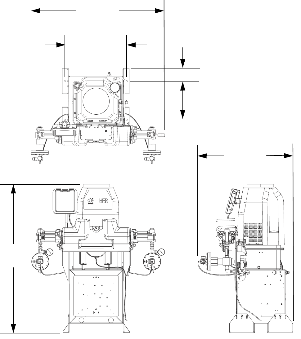
Technical Data
94 3A2175A
Dimensions
ti18219a
58.1 in.
(1476 mm)
51.8 in.
(1316 mm)
37.2 in.
(945 mm)
24 in.
(610 mm)*
15 in.
(381 mm)*
* (4) 5/8” diameter anchor locations
5 in.
(127 mm)*

Technical Data
3A2175A 95

All written and visual data contained in this document reflects the latest product information available at the time of publication.
Graco reserves the right to make changes at any time without notice.
Original instructions. This manual contains English. MM 3A2175
Graco Headquarters: Minneapolis
International Offices: Belgium, China, Japan, Korea
GRACO INC. AND SUBSIDIARIES • P.O. BOX 1441 • MINNEAPOLIS MN 55440-1441 • USA
Copyright 2011, Graco Inc. All Graco manufacturing locations are registered to ISO 9001.
www.graco.com
Graco Standard Warranty
Graco warrants all equipment referenced in this document which is manufactured by Graco and bearing its name to be free from defects in
material and workmanship on the date of sale to the original purchaser for use. With the exception of any special, extended, or limited warranty
published by Graco, Graco will, for a period of twelve months from the date of sale, repair or replace any part of the equipment determined by
Graco to be defective. This warranty applies only when the equipment is installed, operated and maintained in accordance with Graco’s written
recommendations.
This warranty does not cover, and Graco shall not be liable for general wear and tear, or any malfunction, damage or wear caused by faulty
installation, misapplication, abrasion, corrosion, inadequate or improper maintenance, negligence, accident, tampering, or substitution of
non-Graco component parts. Nor shall Graco be liable for malfunction, damage or wear caused by the incompatibility of Graco equipment with
structures, accessories, equipment or materials not supplied by Graco, or the improper design, manufacture, installation, operation or
maintenance of structures, accessories, equipment or materials not supplied by Graco.
This warranty is conditioned upon the prepaid return of the equipment claimed to be defective to an authorized Graco distributor for verification of
the claimed defect. If the claimed defect is verified, Graco will repair or replace free of charge any defective parts. The equipment will be returned
to the original purchaser transportation prepaid. If inspection of the equipment does not disclose any defect in material or workmanship, repairs will
be made at a reasonable charge, which charges may include the costs of parts, labor, and transportation.
THIS WARRANTY IS EXCLUSIVE, AND IS IN LIEU OF ANY OTHER WARRANTIES, EXPRESS OR IMPLIED, INCLUDING BUT NOT LIMITED
TO WARRANTY OF MERCHANTABILITY OR WARRANTY OF FITNESS FOR A PARTICULAR PURPOSE.
Graco’s sole obligation and buyer’s sole remedy for any breach of warranty shall be as set forth above. The buyer agrees that no other remedy
(including, but not limited to, incidental or consequential damages for lost profits, lost sales, injury to person or property, or any other incidental or
consequential loss) shall be available. Any action for breach of warranty must be brought within two (2) years of the date of sale.
GRACO MAKES NO WARRANTY, AND DISCLAIMS ALL IMPLIED WARRANTIES OF MERCHANTABILITY AND FITNESS FOR A
PARTICULAR PURPOSE, IN CONNECTION WITH ACCESSORIES, EQUIPMENT, MATERIALS OR COMPONENTS SOLD BUT NOT
MANUFACTURED BY GRACO. These items sold, but not manufactured by Graco (such as electric motors, switches, hose, etc.), are subject to
the warranty, if any, of their manufacturer. Graco will provide purchaser with reasonable assistance in making any claim for breach of these
warranties.
In no event will Graco be liable for indirect, incidental, special or consequential damages resulting from Graco supplying equipment hereunder, or
the furnishing, performance, or use of any products or other goods sold hereto, whether due to a breach of contract, breach of warranty, the
negligence of Graco, or otherwise.
FOR GRACO CANADA CUSTOMERS
The Parties acknowledge that they have required that the present document, as well as all documents, notices and legal proceedings entered into,
given or instituted pursuant hereto or relating directly or indirectly hereto, be drawn up in English. Les parties reconnaissent avoir convenu que la
rédaction du présente document sera en Anglais, ainsi que tous documents, avis et procédures judiciaires exécutés, donnés ou intentés, à la suite
de ou en rapport, directement ou indirectement, avec les procédures concernées.
Graco Information
For the latest information about Graco products, visit www.graco.com.
TO PLACE AN ORDER, contact your Graco distributor or call to identify the nearest distributor.
Phone: 612-623-6921 or Toll Free: 1-800-328-0211 Fax: 612-378-3505
