Graco 3A2308C Protective Coating Hand Held Paint Sprayer Users Manual Sprayer, Operation Parts Repair (English)
16h960 07082930-6e85-4eb6-9ba0-c28ddb1ed2fc Graco Paint Sprayer 16H960 User Guide |
2015-04-02
: Graco Graco-3A2308C-Protective-Coating-Hand-Held-Paint-Sprayer-Users-Manual-686187 graco-3a2308c-protective-coating-hand-held-paint-sprayer-users-manual-686187 graco pdf
Open the PDF directly: View PDF ![]() .
.
Page Count: 44
- Table of Contents
- Important User Information
- Warnings
- Component Identification
- Operation
- Charging the Battery
- Charger Status Indicator Lights
- Sprayer Status Indicator
- Common Procedures
- Adjusting Pressure
- Setup
- Starting a New Job
- Install/Service Filter (if needed)
- Install Tip/Guard Assembly (if not installed)
- Filling and Installing Cup
- Priming Pump
- Setting Pressure
- Getting Started with Basic Techniques
- Triggering Sprayer
- Aiming Sprayer
- Unclogging Spray Tip/Guard Assembly
- Shutdown and Cleaning
- Cleaning Sprayer Exterior
- Storage
- Parts
- Troubleshooting
- Repair
- Technical Data
- FCC Declaration for Battery Charger
- Notes
- Notes
- Graco Standard Warranty
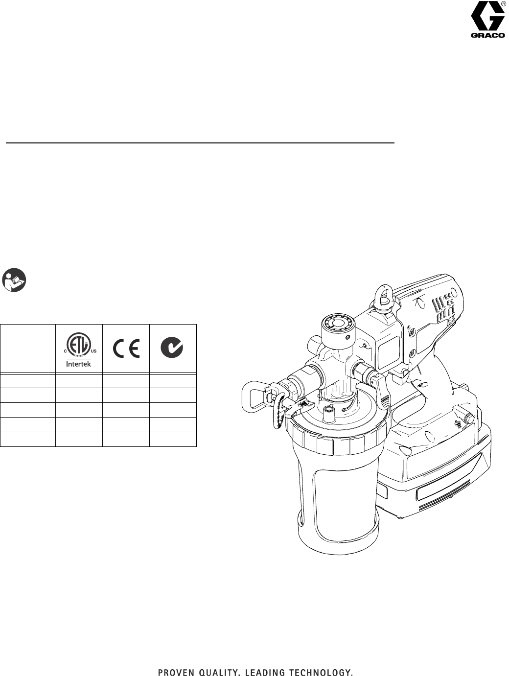
3A2308C
Operation - Parts - Repair
Protective Coating
Hand-Held Paint Sprayer
- For portable spray applications of protective coatings
-
- For professional use only -
- Not approved for use in explosive atmospheres or hazardous locations -
- DO NOT SPRAY ZINC COATINGS OR MATERIALS WITH AGGREGATE.
ACCELERATED PUMP WEAR WILL OCCUR -
4000 psi (27.6 MPa, 276 bar) Maximum Working Pressure
IMPORTANT SAFETY INSTRUCTIONS
Read all warnings and instructions in this
manual. Save these instructions.
Model
16H960 ✓
16N654 ✓
16N927
16N655 ✓
16N656 ✓
EN
ti19340a

Table of Contents
23A2308C
Table of Contents
Warnings . . . . . . . . . . . . . . . . . . . . . . . . . . . . . . . . . . . . . . 3
Component Identification . . . . . . . . . . . . . . . . . . . . . . . . . 6
Operation . . . . . . . . . . . . . . . . . . . . . . . . . . . . . . . . . . . . . . 7
Charging the Battery . . . . . . . . . . . . . . . . . . . . . . . . . . 7
Charger Status Indicator Lights . . . . . . . . . . . . . . . . . . 7
Sprayer Status Indicator . . . . . . . . . . . . . . . . . . . . . . . . 8
Common Procedures . . . . . . . . . . . . . . . . . . . . . . . . . . 9
Adjusting Pressure . . . . . . . . . . . . . . . . . . . . . . . . . . . 10
Setup . . . . . . . . . . . . . . . . . . . . . . . . . . . . . . . . . . . . . 12
Starting a New Job . . . . . . . . . . . . . . . . . . . . . . . . . . . 12
Install/Service Filter (if needed) . . . . . . . . . . . . . . . . . 13
Install Tip/Guard Assembly (if not installed) . . . . . . . . 14
Filling and Installing Cup . . . . . . . . . . . . . . . . . . . . . . 14
Priming Pump . . . . . . . . . . . . . . . . . . . . . . . . . . . . . . . 15
Setting Pressure . . . . . . . . . . . . . . . . . . . . . . . . . . . . . 15
Getting Started with Basic Techniques . . . . . . . . . . . 17
Triggering Sprayer . . . . . . . . . . . . . . . . . . . . . . . . . . . 17
Aiming Sprayer . . . . . . . . . . . . . . . . . . . . . . . . . . . . . . 17
Unclogging Spray Tip/Guard Assembly . . . . . . . . . . . 18
Shutdown and Cleaning . . . . . . . . . . . . . . . . . . . . . . . 19
Cleaning Sprayer Exterior . . . . . . . . . . . . . . . . . . . . . 21
Storage . . . . . . . . . . . . . . . . . . . . . . . . . . . . . . . . . . . . 21
Parts . . . . . . . . . . . . . . . . . . . . . . . . . . . . . . . . . . . . . . . . . 22
Parts List . . . . . . . . . . . . . . . . . . . . . . . . . . . . . . . . . . 23
Troubleshooting . . . . . . . . . . . . . . . . . . . . . . . . . . . . . . . 24
Spray Pattern Diagnostics . . . . . . . . . . . . . . . . . . . . . 26
Repair . . . . . . . . . . . . . . . . . . . . . . . . . . . . . . . . . . . . . . . . 28
Inlet Valve . . . . . . . . . . . . . . . . . . . . . . . . . . . . . . . . . 28
Outlet Valve . . . . . . . . . . . . . . . . . . . . . . . . . . . . . . . . 29
Pressure Control Knob . . . . . . . . . . . . . . . . . . . . . . . . 30
Pump Module/Drive Module . . . . . . . . . . . . . . . . . . . . 31
Pump Rebuild Kit . . . . . . . . . . . . . . . . . . . . . . . . . . . . 32
Clamshell . . . . . . . . . . . . . . . . . . . . . . . . . . . . . . . . . . 33
Motor/Control Board Replacement Kit . . . . . . . . . . . . 35
Switch Assembly . . . . . . . . . . . . . . . . . . . . . . . . . . . . 37
Gear Replacement . . . . . . . . . . . . . . . . . . . . . . . . . . . 39
Technical Data . . . . . . . . . . . . . . . . . . . . . . . . . . . . . . . . . 41
FCC Declaration for Battery Charger . . . . . . . . . . . . . . . 41
Notes . . . . . . . . . . . . . . . . . . . . . . . . . . . . . . . . . . . . . . . . 42
Notes . . . . . . . . . . . . . . . . . . . . . . . . . . . . . . . . . . . . . . . . 43
Graco Standard Warranty . . . . . . . . . . . . . . . . . . . . . . . . 44
Important User Information
Before using your sprayer read this Operation Manual for complete instructions on proper use and safety warnings.
Before using this equipment, be sure to read and follow the information on your container label and ask for a Material Safety
Data Sheet (MSDS) from your supplier. The container label and MSDS will explain the contents of the material and the
specific precautions related to it.
Paints, coatings and clean-up materials generally fit into one of the following 3 basic categories:
WATER-BASED:
The container label should indicate that the material can be cleaned up with soap and water.
Your sprayer is compatible with this type of material. Your sprayer is NOT compatible with harsh cleaners such as
chlorine bleach.
OIL-BASED:
The container label should indicate that the material is COMBUSTIBLE and can be cleaned up with
mineral spirits or paint thinner. The MSDS must indicate that the flash point of the material is above 100° F. Your
sprayer is compatible with this type of material. Use oil-based material outdoors or in a well-ventilated indoor area
with a flow of fresh air. See the safety warnings in this manual.
FLAMMABLE:
This type of material contains flammable solvents such as xylene, toluene, naphtha, MEK, lacquer
thinner, acetone, denatured alcohol, and turpentine. The container label should indicate that this material is
FLAMMABLE. Your sprayer is compatible with this type of material. Use flammable materials outdoors or in a
well-ventilated indoor area with a flow of fresh air. See the safety warnings in this manual.
DO NOT RETURN THIS SPRAYER TO THE STORE!
If you experience problems, contact Graco Product Support at 1-888-541-9788 or visit www.graco.com.
Warnings
3A2308C 3
Warnings
The following warnings are for the setup, use, maintenance, and repair of this equipment. The exclamation point
symbol alerts you to a general warning and the hazard symbols refer to procedure-specific risks. When these
symbols appear in the body of this manual or on warning labels, refer back to these Warnings. Product-specific
hazard symbols and warnings not covered in this section may appear throughout the body of this manual where
applicable.
WARNING
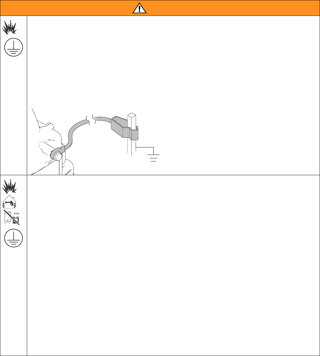
FIRE AND EXPLOSION HAZARD (GROUNDING)
Some oil-based and flammable materials generate static electricity when sprayed. Static electricity creates
an explosion and fire risk. Your sprayer has a ground wire that will conduct the static electricity to earth
ground. The sprayer and all objects in spray area must be properly grounded to protect against static
discharge, sparks or shocks.
• Connect the ground wire when spraying flammable or static producing oil-based materials.
• If there is static sparking or if you feel a shock, stop spraying immediately and connect the sprayer to
earth ground with the ground wire provided.
GROUNDING INSTRUCTIONS
Clamp sprayer ground wire to earth ground.
FIRE AND EXPLOSION HAZARD
Flammable fumes, such as solvent and paint fumes, in work area can ignite or explode. To help prevent
fire and explosion:
• Do not spray flammable or combustible liquids in a confined area.
• Keep spray area well-ventilated. Keep a good supply of fresh air moving through the area.
• Paint or solvent flowing through the sprayer is able to result in static electricity. Static electricity creates
a risk of fire or explosion in the presence of paint or solvent fumes. The sprayer and all objects in spray
area shall be properly grounded to protect against static discharge, sparks, or shocks.
• Always connect the ground wire provided when spraying flammable materials or static producing
oil-based materials. See Grounding Instructions above.
• If there is static sparking or you feel a shock, stop operation immediately and connect sprayer to earth
ground with the ground wire provided.
• Do not spray flammable or combustible materials near open flame or sources of ignition such as
cigarettes, external motors, and electrical equipment.
• Do not operate light switches, engines, or similar spark producing products in the spray area.
• Do not smoke in the spray area.
• Keep spray area clean and free of paint or solvent containers, rags, and other flammable materials.
• Know the contents of the paints and solvents being sprayed. Read all Material Safety Data Sheets
(MSDS) and container labels provided with the paints and solvents. Follow the paint and solvents
manufacturer’s safety instructions.
• Fire extinguisher equipment shall be present and working.
ti19343a

Warnings
43A2308C
WARNINGWARNINGWARNING
WARNING
SKIN INJECTION HAZARD
High-pressure spray is able to inject toxins into the body and cause serious bodily injury. In the event that
injection occurs, get immediate surgical treatment.
• Do not aim the sprayer at, or spray any person or animal.
• Keep hands and other body parts away from the discharge. For example, do not try to stop leaks with any
part of the body.
• Always engage the trigger lock when not spraying. Verify the trigger lock is functioning properly.
• Always use the spray tip guard. Do not spray without spray tip guard in place.
• Use caution when cleaning and changing spray tips. In the case where the spray tip clogs while spraying,
follow the Pressure Relief Procedure for relieving the pressure before reversing or removing the spray tip
to clean.
• Do not leave the unit energized or under pressure while unattended. When the unit is not in use, follow the
Pressure Relief Procedure and engage the trigger lock.
• Check parts for signs of damage. Replace any damaged parts with genuine Graco parts.
• This system is capable of producing 4000 psi. Use replacement parts or accessories that are rated a min-
imum of 4000 psi.
• Do not carry the sprayer with a finger on the trigger.
• Verify that all connections are secure before operating the unit.
• Know how to stop the unit and bleed pressure quickly. Be thoroughly familiar with the controls.
EQUIPMENT MISUSE HAZARD
Misuse can cause death or serious injury.
• Disconnect the battery before servicing.
• Always wear appropriate gloves, eye protection, and a respirator or mask when painting.
• Do not operate or spray near children. Keep children away from equipment at all times.
• Do not overreach or stand on an unstable support. Keep effective footing and balance at all times.
• Stay alert and watch what you are doing.
• Do not operate the unit when fatigued or under the influence of drugs or alcohol.
• Use only in dry locations. Do not expose to water or rain.
• Use in well-lit areas.
• Always replace cracked, broken or missing parts immediately with genuine Graco parts. See Parts List,
page 23.
BATTERY HAZARD
The battery may leak, explode, cause burns, or cause an explosion if mishandled. Contents of an open battery
can cause severe irritation and/or chemical burns. If on skin, wash with soap and water. If in eyes, flush with
water for at least 15 minutes and seek immediate medical attention.
• Replace battery only in a well-ventilated area and away from flammable or combustible materials; includ-
ing paints and solvents.
• When battery is not in use, keep it away from metal objects like keys, nails, screws or other metal objects
that can short circuit the battery terminals.
• Do not throw into fire.
• Charge only with Graco-approved charger as listed in this manual.
• Do not store at temperatures below 32° or above 113° F (0° to 45° C).
• Do not use at temperatures below 40° or above 90° F (4° to 32° C).
• Do not expose battery to water or rain.
• Do not disassemble, crush, or penetrate the battery.
• Do not charge a battery that is cracked or damaged.
• Follow local ordinances and/or regulations for disposal.
Warnings
3A2308C 5
CHARGER ELECTRIC SHOCK, FIRE AND EXPLOSION HAZARD
Improper setup or usage can cause electric shock, fire, and explosion.
• Charge only in a well-ventilated area and away from flammable or combustible materials, including paints
and solvents.
• Do not charge on a combustible or flammable surface.
• Do not leave battery unattended while charging.
• Immediately unplug charger and remove battery when charging is complete.
• Charge only Graco batteries listed in this manual; other batteries may burst.
• Use only in dry locations. Do not expose to water or rain.
• Do not use a charger that is cracked or damaged.
• If the supply cord is damaged, replace the charger or cord, depending on model.
• Never force the battery into the charger.
• When operating a charger outdoors, always provide a dry location and use an extension cord suitable for
outdoor use.
• Disconnect the charger from the outlet before cleaning.
• Ensure that the outside surface of the battery is clean and dry before plugging into the charger.
• Do not attempt to charge non-rechargeable batteries.
• Do not disassemble the charger. Take charger to authorized service center when service or repair is
required.
PRESSURIZED ALUMINUM PARTS HAZARD
Use of fluids that are incompatible with aluminum in pressurized equipment can cause serious chemical reac-
tion and equipment rupture. Failure to follow this warning can result in death, serious injury, or property dam-
age.
• Do not use 1,1,1-trichloroethane, methylene chloride, other halogenated hydrocarbon solvents or fluids
containing such solvents.
• Many other fluids may contain chemicals that can react with aluminum. Contact your material supplier for
compatibility.
TOXIC FLUID OR FUMES HAZARD
Toxic fluids or fumes can cause serious injury or death if splashed in the eyes or on skin, inhaled, or swal-
lowed.
• Read MSDS’s to know the specific hazards of the fluids you are using.
• Store hazardous fluid in approved containers, and dispose of it according to applicable guidelines.
PERSONAL PROTECTIVE EQUIPMENT
Wear appropriate protective equipment when in the work area to help prevent serious injury, including eye
injury, hearing loss, inhalation of toxic fumes, and burns. This protective equipment includes but is not limited
to:
• Protective eyewear, and hearing protection.
• Respirators, protective clothing, and gloves as recommended by the fluid and solvent manufacturer.
WARNINGWARNINGWARNING
WARNING
Component Identification
63A2308C
Component Identification
N
M
K
B
J
H
G
F
E
D
C
A
P
ti19345a
R
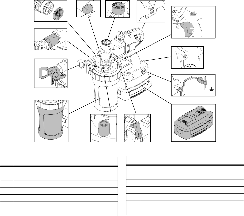
Ref. Description
A Accumulator
B Pressure Control Knob
C Sprayer Status Indicator
D Trigger Lock
E Trigger
F Static Wick
G Ground Wire Assembly with Clamp
H Battery
J Pressure Relief Valve / Prime Valve
KCheck Valve
M Material Cup
N Spray Tip Assembly
P Front Shut-Off Valve
R Material Filter
Ref. Description
Operation
3A2308C 7
Operation
Charging the Battery
Batteries are initially 50% charged to provide optimum
battery life and require charging before first use. It takes
approximately 50 minutes to charge a dead battery to
80%, at which point it can be used. It will take approxi-
mately 75 minutes to fully charge a dead battery.
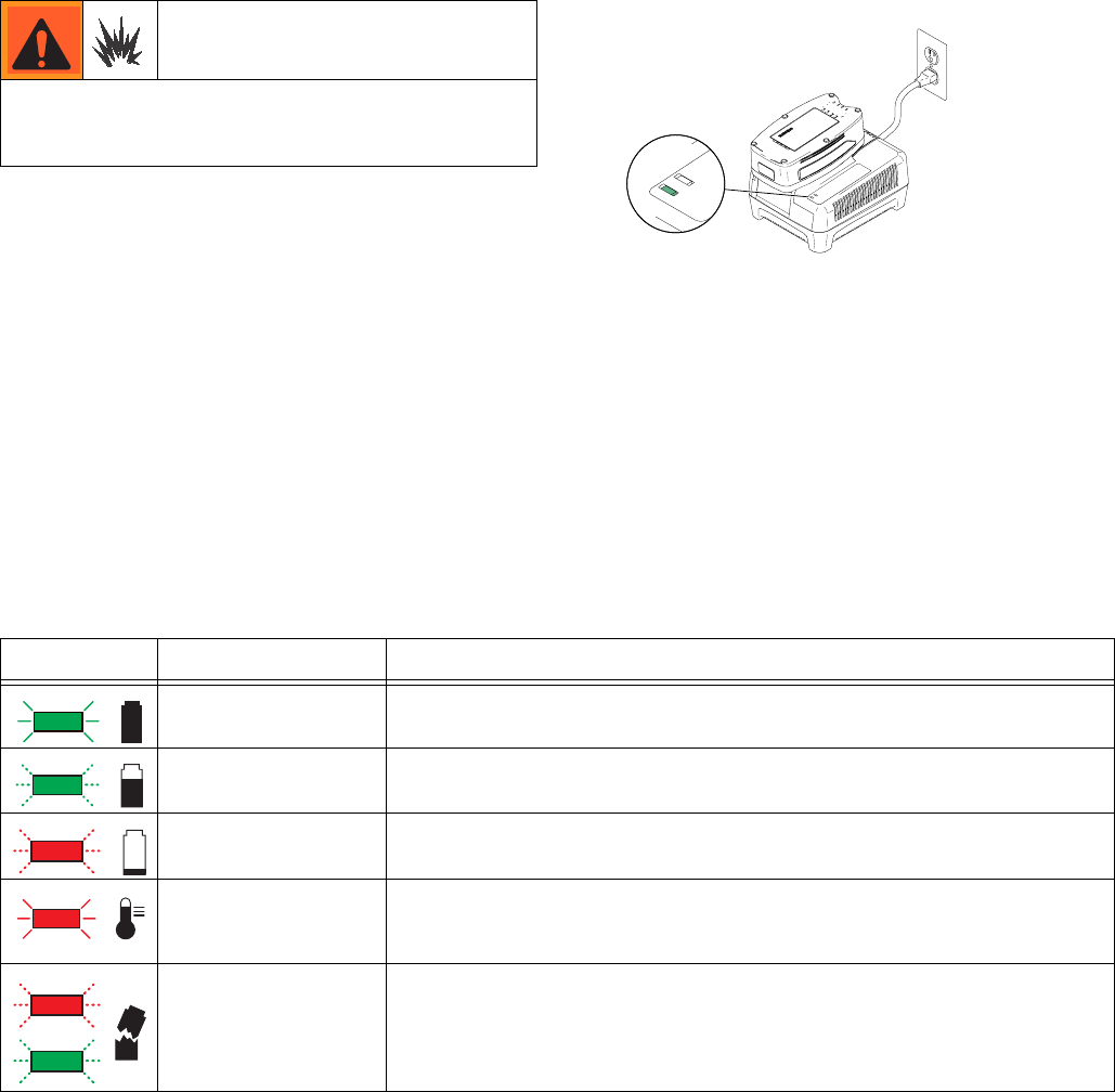
1. Place charger in a dry, well-ventilated area and
away from flammable or combustible materials,
including paints and solvents.
2. Plug charger into an electrical outlet and slide bat-
tery into charger as shown (light will turn on in 5
seconds).
3. When battery becomes fully charged, immediately
unplug the charger from the power supply and
remove the battery from the charger.
NOTE: The amount sprayed with each battery varies
depending on material, spray tip size, battery charge,
and battery temperature. One battery fully charged will
spray up to one gallon. Amount sprayed will be less
depending on spray tip size, material sprayed, life of
battery, temperature, and other environmental factors.
Charger Status Indicator Lights
Replace and charge battery only in a well-ventilated
area and away from flammable or combustible materi-
als, including paints and solvents.
ti19341a
Label Appearance Description
Solid green light Indicates a full charge. Battery can be used.
Flashing green light Battery is charging, indicates 80% charge.
Battery can be used.
Flashing red light Battery is charging, indicates less than 80% charge.
Do NOT use battery.
Solid red light
Battery is too hot or too cold to charge. Remove battery and allow to cool or
warm up before charging. Battery temperature must be between
50° F - 113° F (10° C - 45° C) to charge.
Both lights Battery has internal fault or has experienced damage. Do not use.
Operation
83A2308C
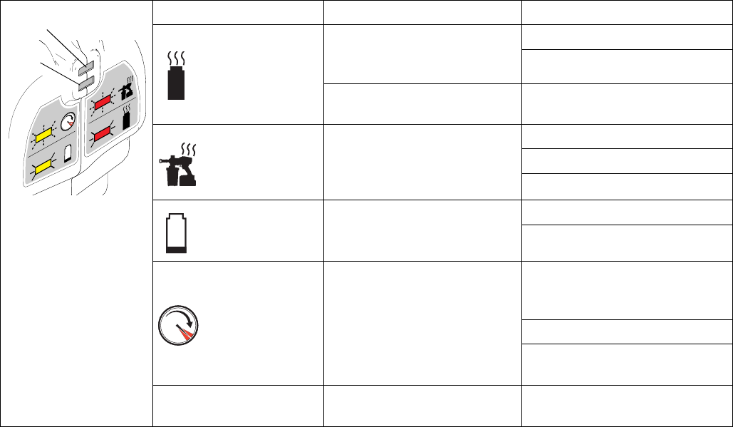
Sprayer Status Indicator
*NOTE: The sprayer status indicator light is visible for 10 seconds after the trigger is released.
No light Normal operation. No action required.
Solid Red
Battery is too hot. Unit will
shut down until battery has
cooled.
Change battery.
Allow battery to cool.
Liquid has contacted control
board. Allow unit to dry.
Flashing Red
Motor is too hot and will shut
down if heavy use continues.
Unit will shut down until motor
has cooled.
Increase tip size.
Turn down pressure.
Let unit cool down.
Solid Yellow Battery is low or
battery is too cold.
Charge battery.
Warm up battery.
Flashing Yellow High pressure signal. Gun will
shut down after 1.5 seconds.
Turn pressure control
counter-clockwise to reduce
pressure.
Increase tip size.
Material is too thin--do not thin
as much.
Solid red and solid yellow Locked motor. Bring sprayer in to service cen-
ter for diagnostics.
ti19361a
Red
Yellow
Operation
3A2308C 9
Common Procedures
Trigger Lock
Follow the Pressure Relief Procedure whenever
you see this symbol.
Prime/Pressure Relief Valve Position
Pressure Relief Procedure
1. Engage trigger lock.
2. Put prime/pressure relief valve UP to release pres-
sure.
Spray Tip Position
Always engage the trigger lock when you stop spraying
to prevent the sprayer from being triggered accidentally
by hand, or if dropped or bumped.
ti14994a
Trigger Locked
Trigger Unlocked
ti14995a
(red ring is visible)
ti19374a
ti19350a
UP position
(For priming and releasing
DOWN position
(Ready to spray)
ti14999a
pump pressure)
ti19347a
ti19346a
Do not operate or spray near children. Do not aim the
sprayer at, or spray any person or animal. Keep hands
and other body parts away from the discharge. For
example, do not try to stop the paint flow with any part
of the body.
This sprayer builds up an internal pressure of 4000 psi
during use. This equipment stays pressurized until
pressure is manually relieved. To help prevent serious
injury from pressurized fluid, such as skin injection,
splashing fluid and moving parts, follow the Pressure
Relief Procedure when you stop spraying and before
cleaning, checking, or servicing the equipment.
Always perform Pressure Relief Procedure before
adjusting spray tip position.
ti19350a
ti14999a
ti19347a
Tip Forward
(SPRAY position)
Tip Reversed
(UNCLOG position)
ti14991a
ti14985a
ti15510a
ti19371a ti19370a
ti15510a
Operation
10 3A2308C
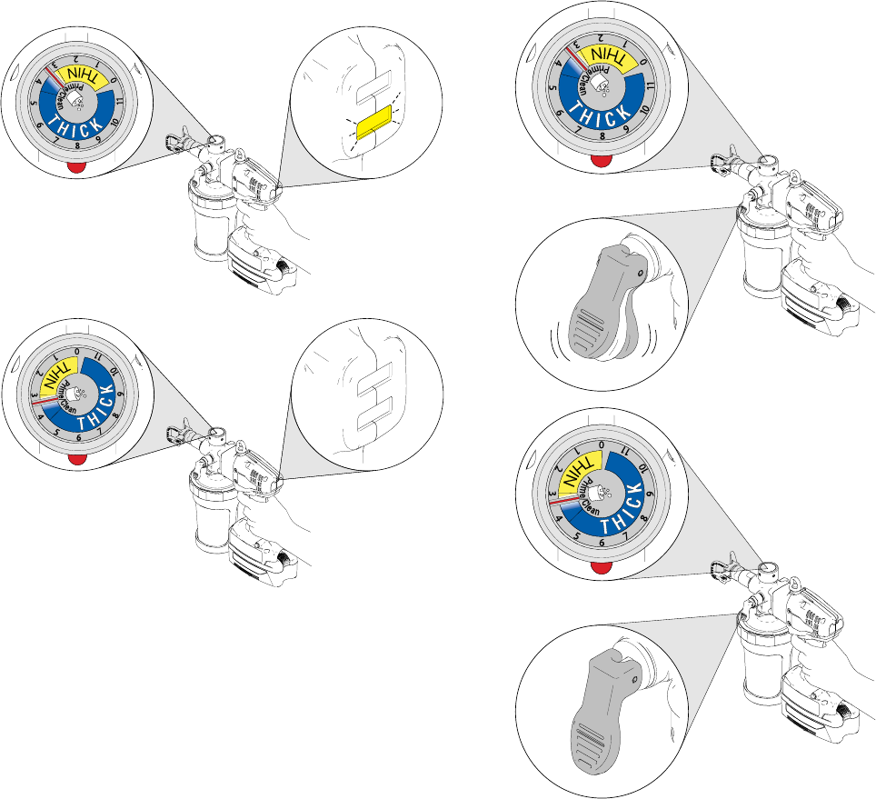
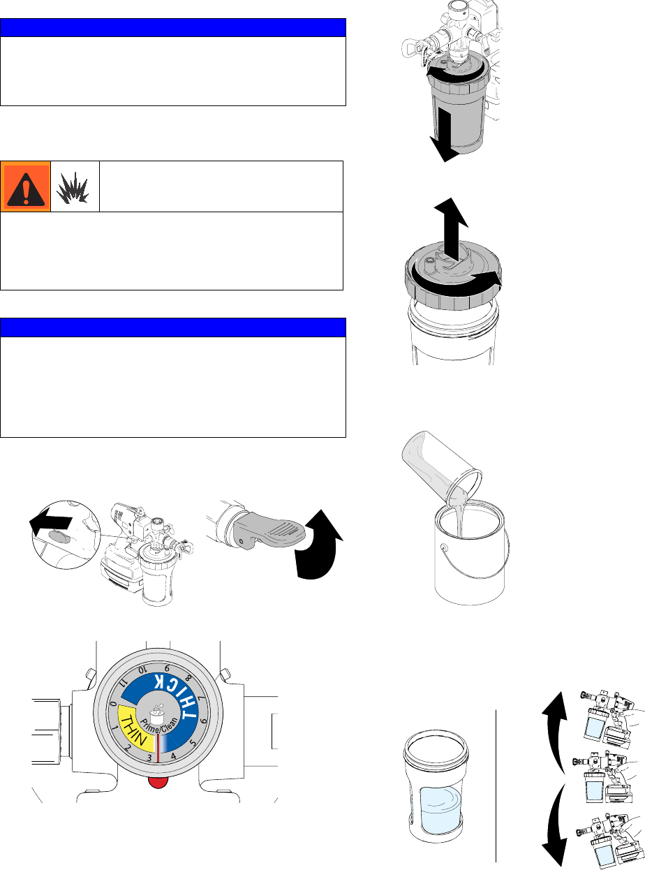
Adjusting Pressure
NOTE: Spraying water, solvents, and thin materials
(low viscosity materials) at high pressure (setting “2” or
higher with yellow light flashing) can result in temporary
pump leaking. To avoid, read and follow instructions
(Quick Guide or Manual) on how to properly adjust
pressure.
NOTE: To reduce overspray and extend battery life,
always spray at lowest pressure that results in an
acceptable spray pattern.
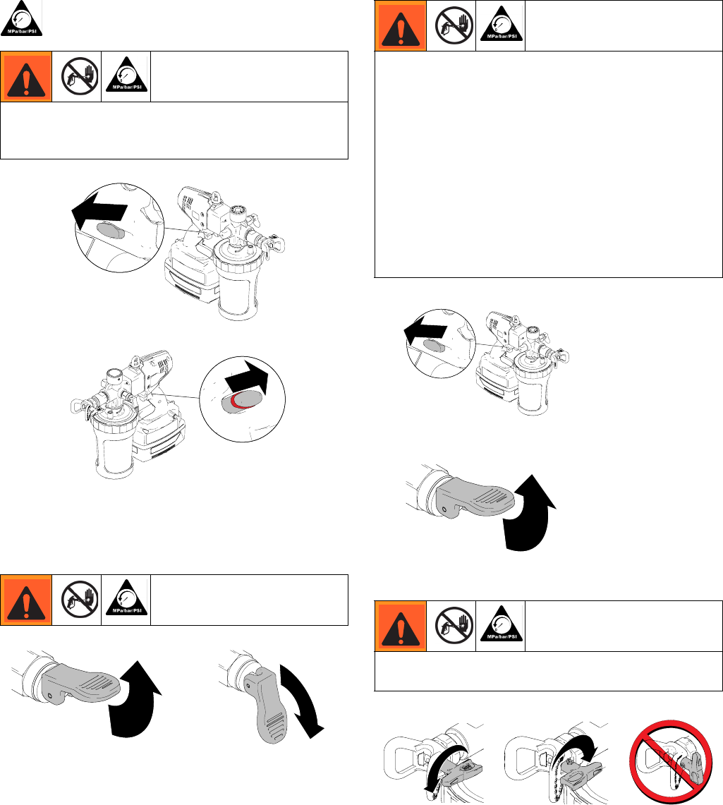
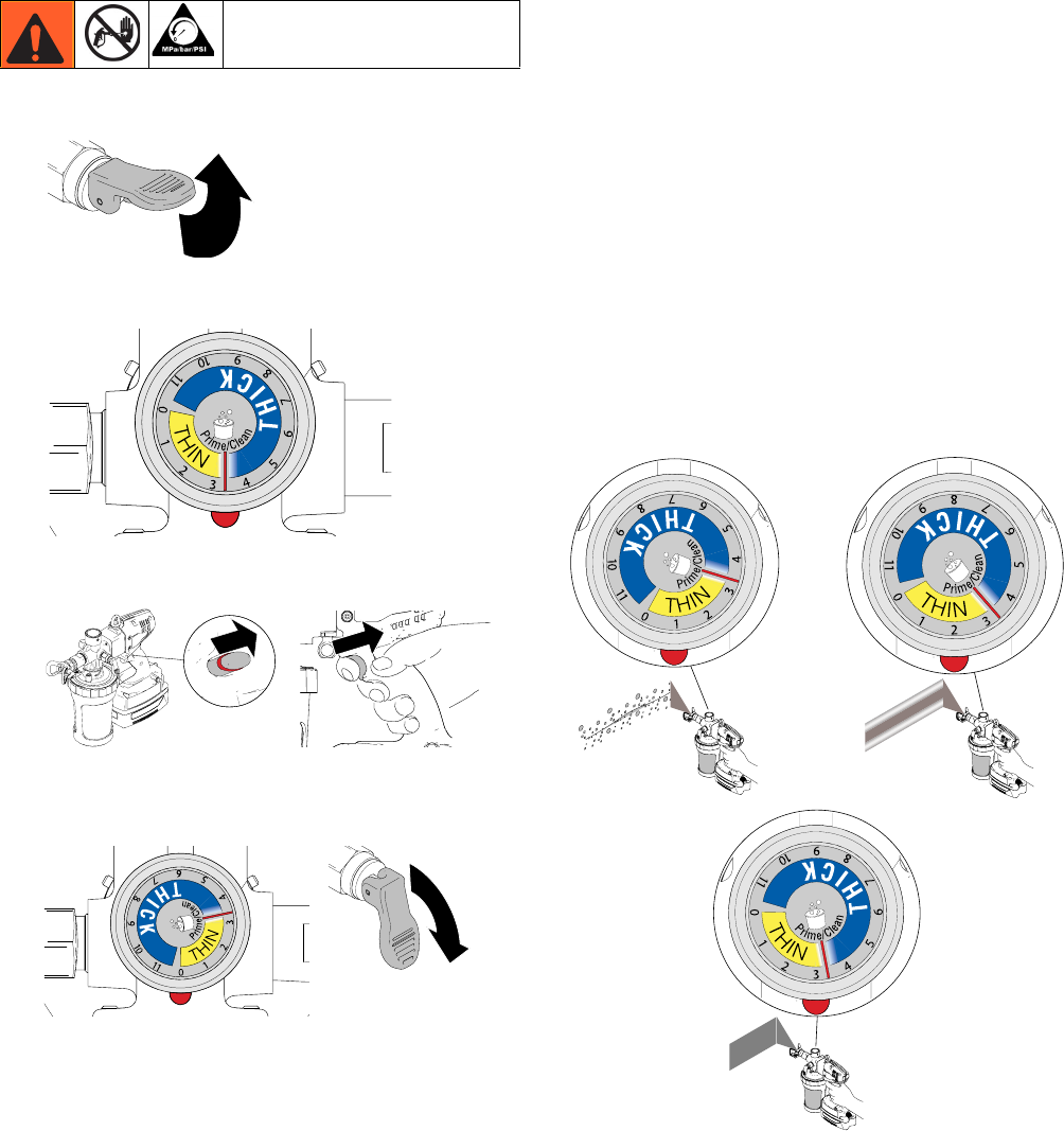
1. Put the pressure relief valve UP to relieve pressure.
2. Turn pressure control knob:
Clockwise to INCREASE pressure, or
Counter-clockwise to DECREASE pressure.
3. Dial in pressure by spraying material on a scrap
material.
4. You MUST start with dial at “1” and gradually
increase by increments of “1” or less until desired
spray pattern is achieved. Put pressure relief handle
in UP position to turn pressure control knob, then
return handle to DOWN position to spray.
ti19372a
ti19347a
0 1 2 3 4 5 6 7 8 9 10 11
ti19407a
THIN
MATERIAL
THICK
MATERIAL
ti19353a
ti19408a
ti19409a
Operation
3A2308C 11
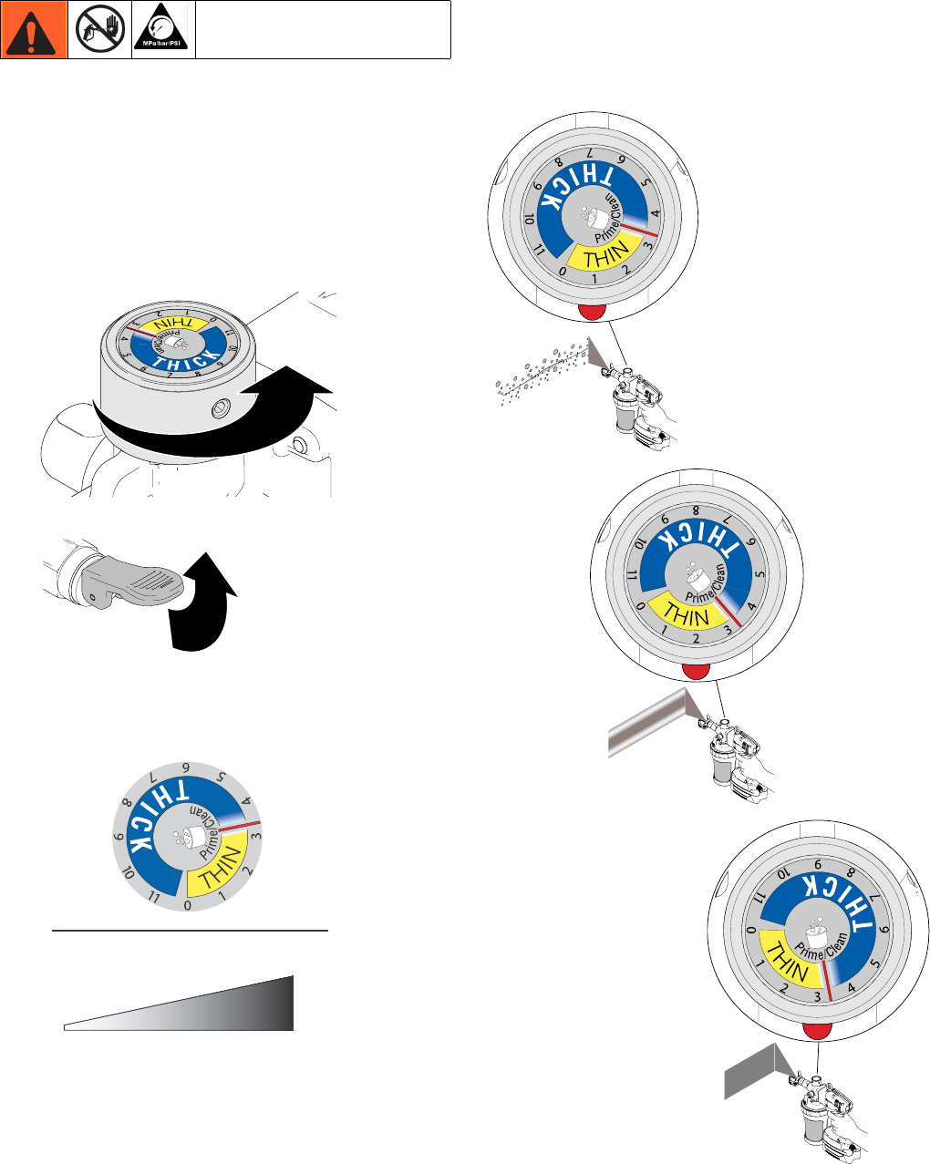
5. If yellow light is flashing while triggering, pressure is
set too high. You MUST turn down pressure until
yellow light no longer flashes, increase tip size, or
do not thin material as much.
6. If pressure relief valve is vibrating, pressure is set
too high. You MUST turn down pressure, increase
tip size, or do not thin material as much.
NOTE: Thin materials will generally require a low
setting and thick materials will generally require a
high setting.
IMPORTANT!
After storage, the piston seals need to be energized
prior to next use to prevent leakage. To energize, follow
steps below:
1. Prime system with flushing fluid.
2. Spray at low pressure setting “1” for 10 seconds.
3. Drain fluid. You are now ready to spray.
ti19655a
ti19654a
ti19656a
ti19653a
Operation
12 3A2308C
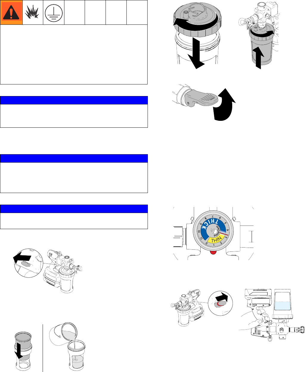
Setup
Starting a New Job
1. Engage trigger lock.
2. Install liner into cup and fill liner 1/2 full with appro-
priate cleaning fluid for material about to be
sprayed.
3. Thread lid onto cup and connect cup to sprayer.
4. Put prime/pressure relief valve in UP position.
NOTE: After storage, the piston seals need to be
energized prior to next use to prevent leakage. To
energize, follow steps below:
a. Prime system with flushing fluid.
b. Spray at low pressure setting “1” for 10 sec-
onds.
c. Drain fluid. You are now ready to spray.
5. You MUST set pressure control to setting “1”.
6. Disengage trigger lock, turn sprayer upside-down
and trigger for approximately 5 seconds to recircu-
late material.
Flammable fumes (such as solvent and paint fumes) in
work area can ignite or explode.
See Grounding Instructions, page 3.
Do not spray flammable or combustible liquids in a con-
fined area.
Keep spray area well-ventilated. Keep a good supply
of fresh air moving through the area.
NOTICE
Your sprayer is NOT compatible with harsh cleaners
such as chlorine bleach. Using these cleaners will
cause damage to the sprayer.
NOTICE
Always flush any cleaning material from the previous
use before starting a new job. If the new spraying
material is not compatible with leftover material in the
pump, adverse reactions could ruin new material.
NOTICE
Do NOT spray zinc coatings or materials with
aggregate. Accelerated pump wear will occur.
ti19350a
ti19348a
ti19384a
ti19354a
ti19347a
ti19374a
Operation
3A2308C 13
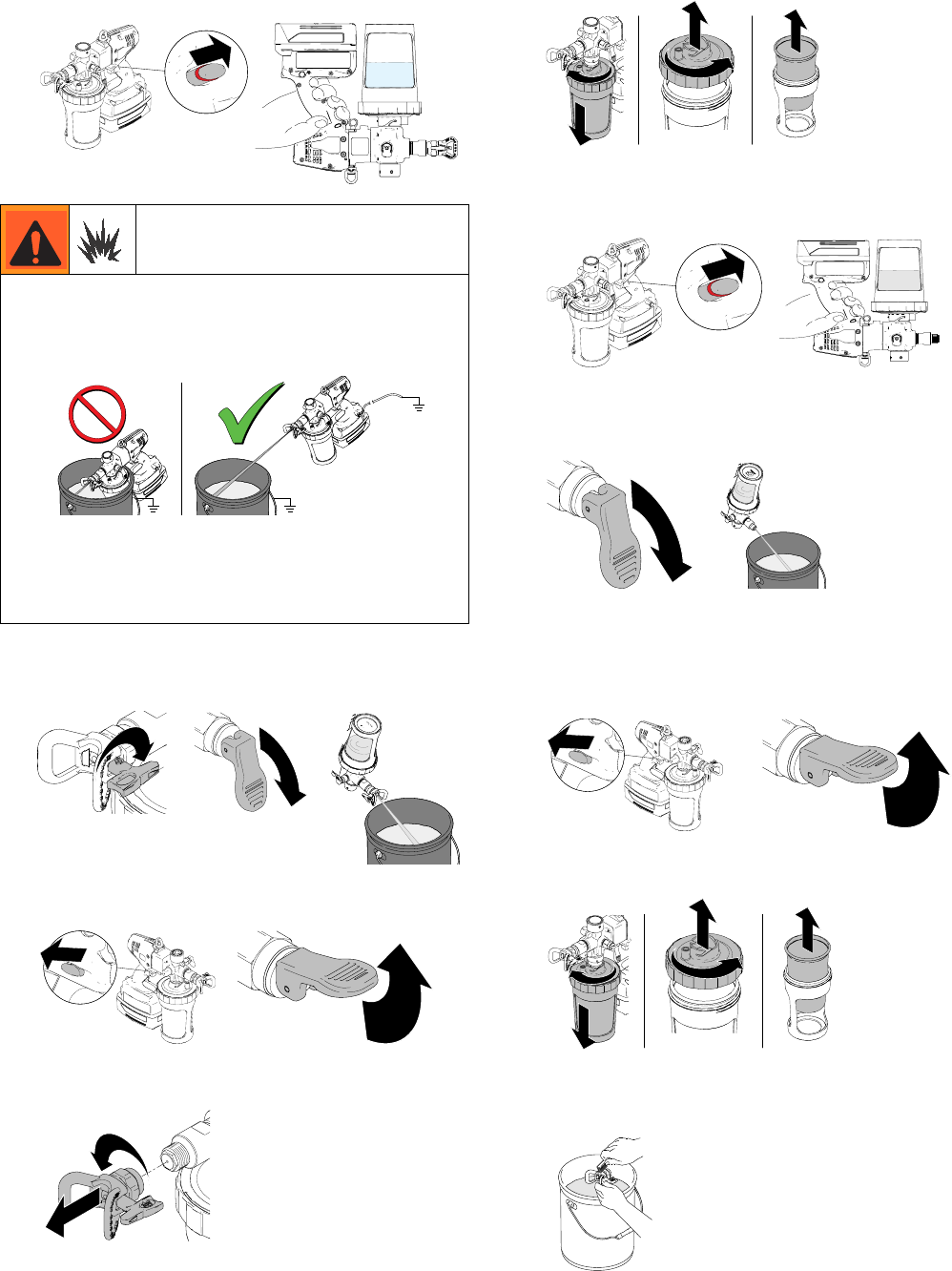
7. Reverse tip to UNCLOG position. Put prime/pres-
sure relief valve DOWN to spray position and trigger
sprayer through tip into waste area for 1- 2 seconds.
8. Engage trigger lock and put prime/pressure relief
valve UP to release pressure.
9. Remove material cup.
10. Disengage trigger lock, put prime/pressure relief
valve DOWN to spray position, hold sprayer slightly
above material cup and pull trigger to discharge fluid
from pump.
11. Put prime/pressure relief valve UP and pull trigger to
finish flushing material.
12. Properly discard any material in cup.
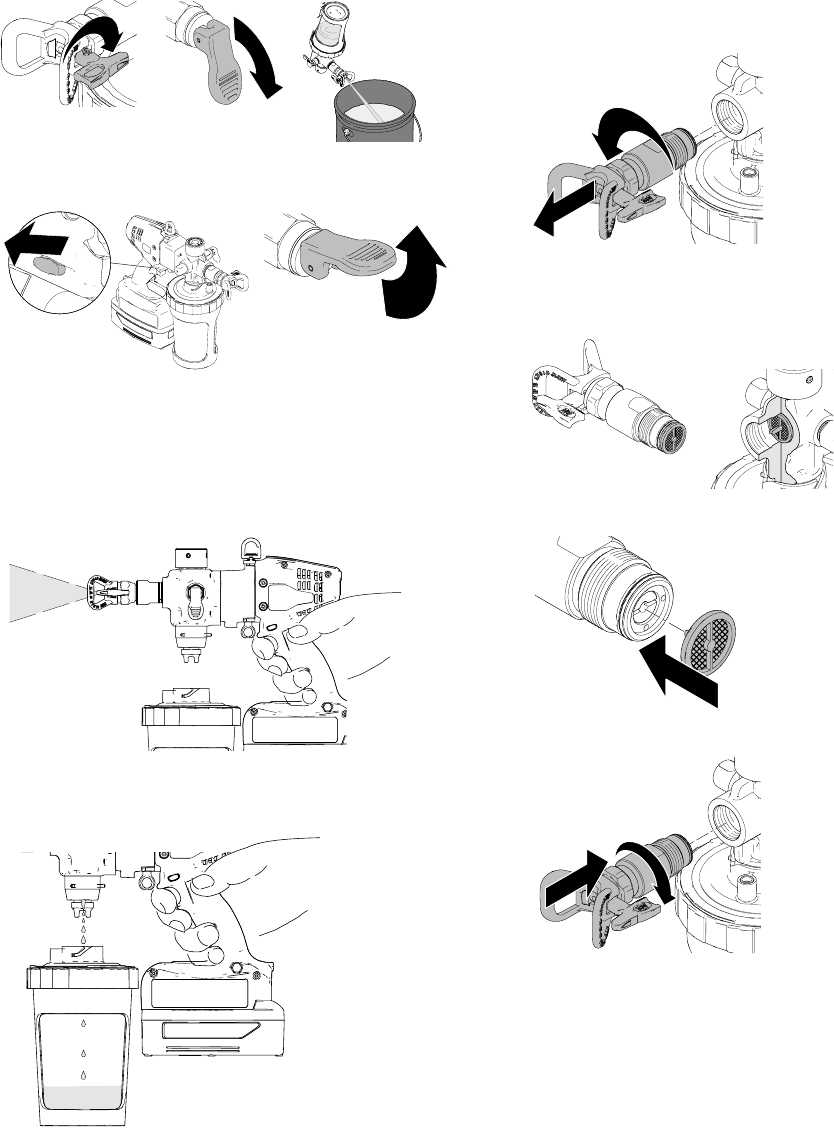
Install/Service Filter (if needed)
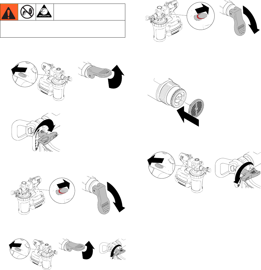
1. Perform Pressure Relief Procedure, page 9.
2. Unthread front valve housing from sprayer.
3. Filter should come out of pump housing with valve.
If filter remains in housing, remove it by hand or with
pliers if necessary.
4. Install properly-sized filter (if needed).
5. Reassemble valve housing to pump.
ti14995a
ti19346a
ti19366a
ti19370a
ti19347a
ti19350a
ti19403a
ti19401a
ti19362a
ti19342a
ti19349a
ti19364a
Operation
14 3A2308C
Install Tip/Guard Assembly
(if not installed)
NOTE: Only use Graco Tip/Guard assemblies.
1. Engage trigger lock and put prime/pressure relief
valve UP to relieve pressure.
2. Screw Tip/Guard Assembly onto sprayer. Tighten
retaining nut until completely engaged with sprayer.
Do not overtighten nut.
Filling and Installing Cup
1. Engage trigger lock and put prime/pressure relief
valve UP to relieve pressure.
2. Install liner into material cup and fill with material.
3. Thread lid onto material cup and connect cup to
sprayer. NOTE: Do not squeeze sides of cup while
threading lid onto cup.
NOTE: Check valve can be oriented in three loca-
tions when attached to cup. If squeezing liner with
left hand, position check valve on left side. If
squeezing liner with right hand, position check valve
on right side.
4. Squeeze liner to purge air through check valve until
material is present at check valve.
NOTE: To purge the maximum amount of air out of
the liner, slightly tilt the sprayer so the check valve is
the highest point.
This equipment stays pressurized until pressure is
manually relieved. To help prevent serious injury
from pressurized fluid, such as skin injection,
splashing fluid and moving parts, follow the
Pressure Relief Procedure when you stop spraying
and before cleaning, checking, or servicing the
equipment.
Do NOT place hands in front of tip.
ti19347a
ti19350a
ti19369a
ti19347a
ti19350a
ti19348a
ti19354a ti19384a
ti19355a
ti19367a
Operation
3A2308C 15
Priming Pump
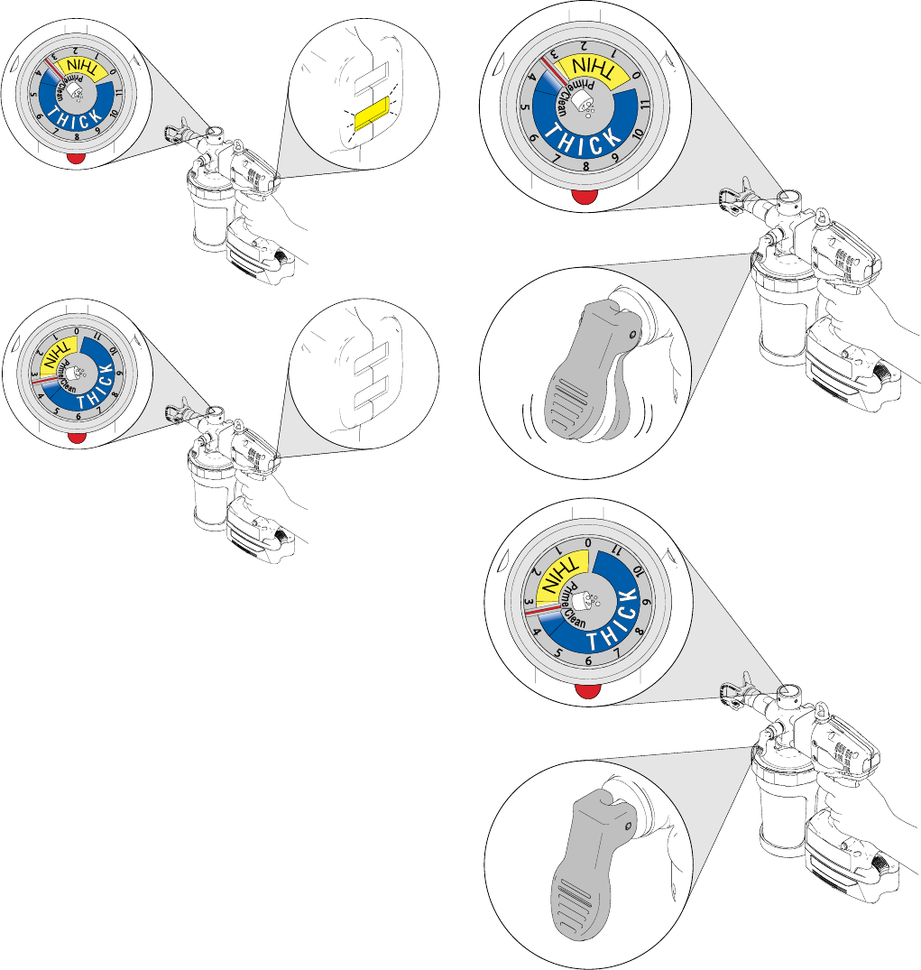
1. Put prime/pressure relief valve UP to priming posi-
tion.
2. Turn pressure control knob to prime/clean position
in line with red indicator dot.
3. Disengage trigger lock and trigger sprayer for three
seconds, then release trigger.
4. Turn pressure control knob counter-clockwise to
lowest position. Put prime/relief valve to DOWN
position to spray.
NOTE: A small amount of air may be introduced into
the cup from the pump while priming. Slightly tip unit
and squeeze liner to purge final amount of air if
desired.
Setting Pressure
NOTE: Spraying water, solvents, and thin materials (low
viscosity materials) at high pressure (setting “2” or
higher with yellow light flashing) can result in temporary
pump leaking. To avoid, read and follow instructions
(Quick Guide or Manual) on how to properly adjust pres-
sure.
1. To reduce overspray and extend battery life, always
spray at lowest pressure that produces an accept-
able spray pattern.
2. Dial in pressure by spraying material on a scrap
material.
3. You MUST start with dial at “1” and gradually
increase by increments of “1” or less until desired
spray pattern is achieved. Put pressure relief handle
in UP position to turn pressure control knob, then
return handle to DOWN position to spray.
NOTE: After storage, the piston seals need to be
energized prior to next use to prevent leakage. To
energize, follow steps below:
a. Prime system with flushing fluid.
b. Spray at low pressure setting “1” for 10 sec-
onds.
c. Drain fluid. You are now ready to spray.
ti19347a
ti19357a
ti19359a
ti19374a
ti19346a
ti19351a
ti19353a ti19408a
ti19409a
Operation
16 3A2308C
4. If yellow light is flashing while triggering, pressure is
set too high. You MUST turn down pressure until
yellow light no longer flashes, increase tip size, or
do not thin material as much.
5. If pressure relief valve is “popping”, pressure is set
too high. You MUST turn down pressure, increase
tip size, or do not thin material as much.
NOTE: If not enough pressure can be achieved for
an acceptable pattern, reduce tip orifice size and
repeat steps. If acceptable pattern is still not
achieved, material might need to be thinned or
heated (see material manufacturing data sheet for
thinning and heating instructions).
ti19655a
ti19654a
ti19656a
ti19653a
Operation
3A2308C 17
Getting Started with Basic
Techniques
Use a piece of scrap cardboard to practice these basic
spraying techniques before you begin spraying the sur-
face.
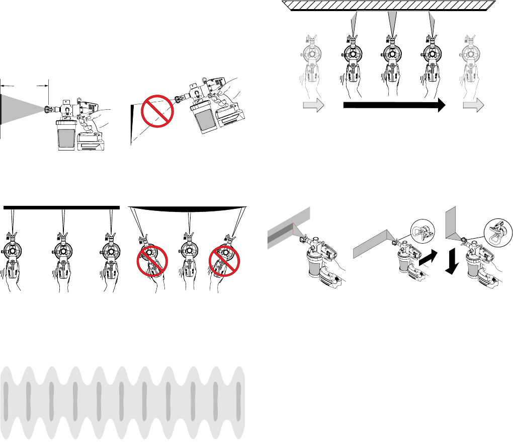
Hold sprayer 10 in. (25 cm) from surface and aim
straight at surface. Tilting sprayer to direct spray angle
causes an uneven finish.
Flex wrist to keep sprayer pointed straight. Fanning
sprayer to direct spray at angle causes uneven finish.
NOTE: How fast you move the sprayer will affect spray
application. If material is pulsating (see below), you are
moving too fast. If material runs, you are moving too
slow. See Troubleshooting, page 24.
Triggering Sprayer
Pull trigger after starting stroke. Release trigger before
end of stroke. Sprayer must be moving when trigger is
pulled and released.
Aiming Sprayer
Aim tip of sprayer at bottom edge of previous stroke,
overlapping each stroke by half.
ti19391a
(25 cm)
10 in.
even
thin
thick
uneven
finish
finish
ti19387a ti19392a
even finish thin thick thin
Pulsating Material
ti19393a
Start Moving Pull Trigger Release Trigger
ti19389a
ti19388a
ti19390a
Operation
18 3A2308C
Unclogging Spray Tip/Guard
Assembly
1. To unclog tip obstruction, engage trigger lock and
put prime/pressure relief valve UP to relieve pres-
sure.
2. Reverse spray tip to UNCLOG position.
3. Aim sprayer at waste area, disengage trigger lock,
and put prime/pressure relief valve DOWN to spray
position. Pull trigger to clear clog.
4. Engage trigger lock. Put prime/pressure relief valve
UP to relieve pressure and rotate spray tip back to
SPRAY position.
5. Disengage trigger lock, put prime/pressure relief
valve DOWN to spray position, and resume spray-
ing.
6. If tip is still clogged, it may be necessary to repeat
steps 1 - 5 and rotate the tip from SPRAY to
UNCLOG several times. Repeat step 1 to release
pressure, remove and clean filter, or replace with
new tip assembly.
7. When obstruction is cleared, engage trigger lock
and rotate arrow-shaped handle back to SPRAY
position.
Always perform the Pressure Relief Procedure
(page 9) before unclogging spray tip.
ti19350a
ti19347a
ti19370a
ti19374a ti19346a
ti19350a
ti19347a
ti19371a
ti19374a ti19346a
ti19349a
ti19350a
ti19371a
Operation
3A2308C 19
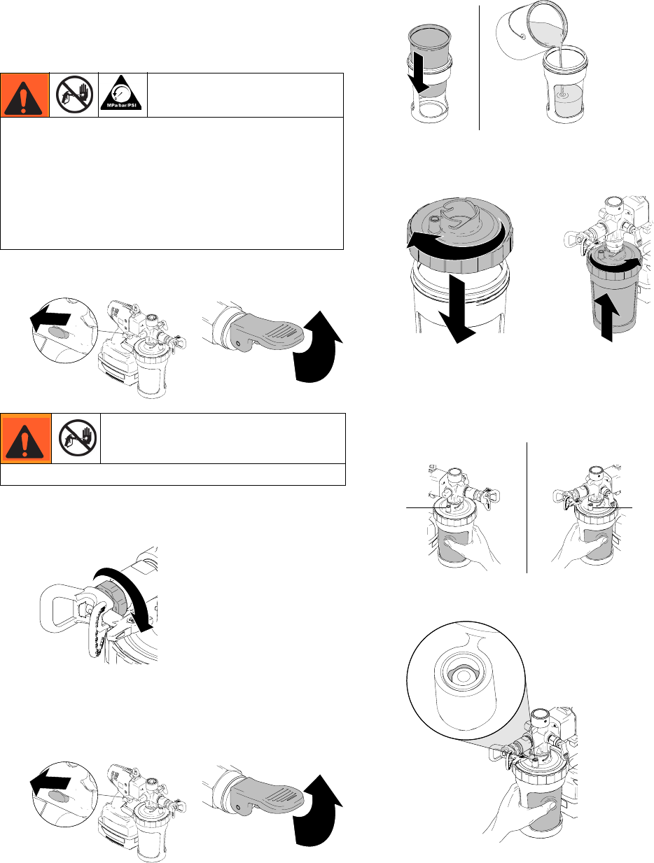
Shutdown and Cleaning
Flushing Sprayer
1. Engage trigger lock and put prime/pressure relief
valve UP to release pressure.
2. Turn pressure control knob to prime/clean position.
3. Remove cup from sprayer.
4. Remove lid from cup.
5. Remove material liner and lid from cup and properly
dispose. Properly dispose any excess material left
in the liner.
6. Insert a new liner into cup and fill 1/2 full with appro-
priate flushing fluid. Screw on lid and attach cup to
sprayer. Shake sprayer to move flushing fluid
around and clean all wetted areas inside cup.
NOTICE
Failure to properly clean sprayer after each use will
result in hardened materials, damage to the sprayer, and
the warranty will no longer be valid. Do not store solvents
other than mineral spirits in sprayer.
Do not spray solvents through the spray tip. Clean the tip
in a bucket of compatible solvent.
Keep spray area well-ventilated. Keep a good supply of
fresh air moving through the area.
NOTICE
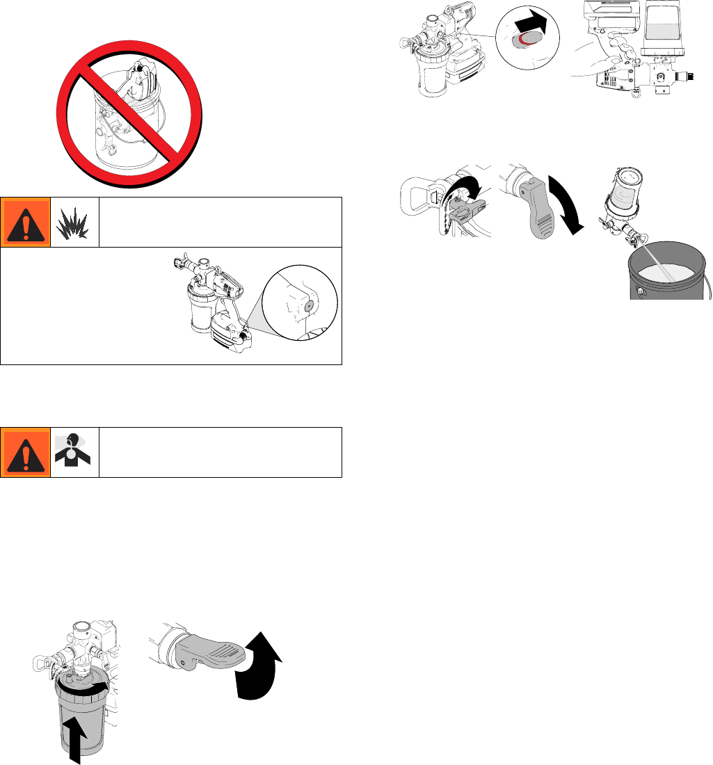
Protect the internal parts of this sprayer from water.
Do not submerge the sprayer in cleaning fluid. Openings
in shroud allow cooling of mechanical parts and electron-
ics inside. If water or cleaning fluid gets into these open-
ings, the sprayer could malfunction or become
permanently damaged.
ti14994a
ti19347a
ti19350a
ti19357a
ti19360a
ti19363a
ti15000a
ti19352a
ti19365a
Operation
20 3A2308C
7. Disengage trigger lock, turn sprayer upside-down
and trigger for approximately 15 seconds to
recirculate material.
8. Reverse tip to UNCLOG position. Put prime/pres-
sure relief valve DOWN to spray position and trigger
sprayer through tip into waste area for 1- 2 seconds.
9. Engage trigger lock. Put prime/pressure relief valve
in UP position.
10. Unthread tip/guard from sprayer and soak in appro-
priate flushing fluid.
11. Remove cup and properly dispose contaminated
fluid.
12. Refill liner 1/2 full. Disengage trigger lock, turn
sprayer upside-down and trigger sprayer for
approximately 15 seconds to recirculate material.
13. Put prime/pressure relief valve DOWN to spray
position. Spray the remaining amount of cleaning
fluid through the front of the sprayer.
14. If sprayer is not completely clean, repeat steps 11
and 12.
15. Engage trigger lock and put prime/pressure relief
valve UP to release pressure.
16. Remove material liner and lid and properly dispose.
Properly dispose used fluid.
17. Clean Spray Tip/Guard assembly with clean flush-
ing fluid. Use a soft brush to loosen and remove
dried material if needed.
To avoid serious injury or damage to equipment, do not
expose the sprayer electronics to flushing solvents.
Keep sprayer at least 10 in. above the rim of the con-
tainer when flushing.
Keep spray area well-ventilated. Keep a good supply
of fresh air moving through the area. When flushing
with solvents, always ground the sprayer and waste
container.
ti14994a
ti19374a
ti19798a
ti14995a
ti19346a
ti19366a
ti19370a
ti19350a ti19347a
ti19386a
ti19385a
ti19374a ti19358a
ti19346a ti19404a
ti19350a ti19347a
ti19385a
ti19344a
Operation
3A2308C 21
Cleaning Sprayer Exterior
Wipe paint off outside of sprayer using a soft cloth
moistened with water or flushing fluid. Do NOT sub-
merge the sprayer or pump.
Storage
1. Fill material cup 1/3 full with mineral spirits solvent
or dilute a 4 oz. bottle of Pump Armor concentrate
with an additional 4 oz. of water in material cup and
liner.
2. Connect cup to sprayer, put prime/pressure relief
valve to UP position.
3. Disengage trigger lock, turn sprayer upside-down
and trigger for approximately 10 seconds to recircu-
late material.
4. Reverse tip to UNCLOG position. Put prime/pres-
sure relief valve DOWN to spray position and trigger
sprayer through tip into waste area for 1- 2 seconds.
5. Properly dispose of used storage fluid from material
cup.
6. Recharge battery to full charge before storage. See
Charging the Battery, page 7.
7. Store sprayer indoors in a cool, dry place. Never
store sprayer with material in the cup.
This sprayer is equipped
with a static wick that
reduces the build up of
static charge to reduce the
risk of fire and explosion.
KEEP THIS SURFACE
CLEAN OF OVERSPRAY.
ti19400a
ti19405a
ti19384a
ti19347a
ti19374a ti19358a
ti19370a ti19346a
ti19366a
Parts
22 3A2308C
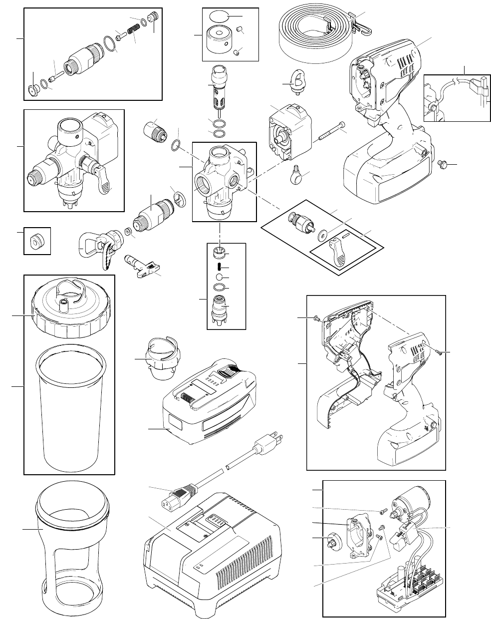
Parts
62
6
3
2
13
4
10
11
18
7
16
19
15
17
61
20
21
22
24
25
26
27
28
29
30
31
39
40
41
42
43
44
45
36
35
37
38
46
47
48
49
32
33
3434
50 51
52
53
54
55
57
60
58
56
59
64
18
63
ti19153a
65
Parts
3A2308C 23
Parts List
Ref. Part Description Qty.
2 16P165 KIT, lid, liner, 25 pack 1
3 16P166 KIT, lid, 25 pack 1
4 16P167 KIT, plug, cup (6 pack) 1
6 16P169 KIT, cup 1
7 16P170 KIT, filter, 30 mesh, 10 pack 1
16P171 KIT, filter, 60 mesh, 10 pack 1
16P172 KIT, filter, 100 mesh, 10 pack 1
10 16P173 KIT, battery, 28V, lithium-ion 1
11 KIT, module, drive
16P174 Models 16H960, 16N927 1
16P175 Models 16N654, 16N655, 16N656 1
13 KIT, charger, battery
*16P177 120V Models 16H960, 16N654 1
**16P178 240V Models 16N927, 16N655, 16N656 1
15 16P179 KIT, pump, rebuild 1
16 16P180 KIT, accumulator, replacement 1
17 16P181 KIT, prime valve, replacement 1
18 16P182 KIT, front shutoff valve, replacement 1
19 262601 KIT, replacement, handle, prime valve 1
20 16M558 SCREW, thumb 1
21 16P284 SCREW, cap, socket head 1
22 16P669 SWIVEL 1
24 16P451 KIT, repair, intake valve 1
25 16N586 GUIDE, ball, inlet 1
26 15R867 SPRING, compression 1
27 16N589 BALL, stainless steel 1
28 109450 PACKING, o-ring 1
29 16N848 HOUSING, intake 1
30 LTX517 TIP, spray 517, RAC X 1
31 16P452 KIT, repair, outlet valve 1
32 16P935 KIT, repair, pressure knob 1
33 16P894 LABEL, control 1
34 16P285 SCREW, set, cup, socket, HD 2
35 16P164 KIT, pump, replacement, HD 1
36 16P183 KIT, motor, replacement 1
37 KIT, repair, clamshell
16P962 Models 16H960, 16N927 1
16P961 Models 16N654, 16N655, 16N656 1
38 246215 GUARD, RAC X 1
39 246453 OneSeal
™
, RAC X (5 pack) 1
40 16P966 STRAP, shoulder 1
41 237686 WIRE, ground assembly with clamp 1
42 124165 SCREW, BHCS, M5, 0.8 x 10, ss 4
43 119236 SCREW, mach, torx pan hd 10
44 112161 SCREW, mach, hex, washer, hd 1
45 278345 SWITCH, assembly 1
46 115263 SCREW, cap, socket, head 3
47 POWER CORD 1
16N441 U.S.
16N442 Europe
16P074 Australia
16P076 Italy
16P077 Denmark
16P078 Swiss
16P411 UK
48 16N510 GEAR, reducer 1
49 24P203 HOUSING, drive 1
50 109450 PACKING, o-ring 1
51 111116 PACKING, o-ring, seat 1
52 102982 PACKING, o-ring 1
53 16M574 SEAT, assembly 1
54 104319 PACKING, o-ring 1
55 16M569 NEEDLE, assembly, HD 1
56 111603 PACKING, o-ring, PTFE 1
57 16M571 CAP, needle 1
58 16C354 SPRING, compression 1
59 16P303 PACKING, o-ring 1
60 16M572 RETAINER, spring 1
61 16N602 DISK, toggle knob 1
62 121817 SCREW, cap, socket HD, m4 1
63 248936 KIT, accessory, RAC X 1
64 109575 SCREW, flange, hex HD 2
65 16N180 HOUSING, gear, machining 1
*** Warning Label Kit (Not Shown)
16T263 ENG/FRA/SPA Models 16H960, 16N654
16T264 SPA/POR/ITA Model 16N927
16T265 EU Model 16N655
16T266 ASIA/ANZ Model 16N656
*** Includes 16N441
*** Includes 16N441, 16N442, 16P074
***
Replacement Danger and Warning labels are
available at no cost.
Ref. Part Description Qty.
Troubleshooting
24 3A2308C
Troubleshooting
Check everything in this Troubleshooting Table before
you bring the sprayer to an authorized service center.
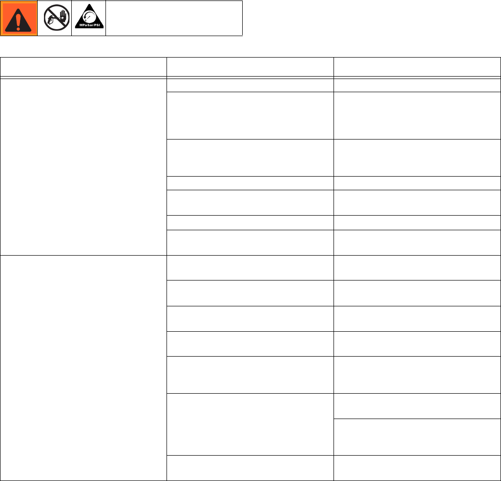
Problem Cause Solution
Sprayer makes no sound when
trigger is pulled
Trigger is locked. Disengage trigger lock. See page 9.
Status Indicator Light is solid YELLOW
when triggering, indicating that the bat-
tery charge is low, or the battery is too
cold.
Replace with charged battery and
place old battery in charger, or allow
battery to warm up.
Status Indicator Light is solid RED
when triggering, indicating that the bat-
tery is too hot to operate.
Allow battery to cool.
Battery is not installed or is damaged. Install battery or replace.
Prime/Pressure Relief valve is in UP
position.
Put valve DOWN to spray position.
Tip is not in SPRAY position. Turn tip to SPRAY position.
Pump is clogged, frozen, or has debris
inside.
See Repair manual.
Sprayer makes sound but no material
is sprayed when trigger is pulled
Sprayer is not primed or air is in
material cup.
Prime the pump. See Starting a new
Job (or Refilling the Cup), page 12.
Tip is clogged. See Unclogging Tip/Guard
Assembly, page 18.
Tip filter is clogged. Remove and clean tip filter. See
Install/Service Filter, page 13.
No or low material in liner. Refill liner with material and prime the
pump.
Inlet ball is stuck from material
residue left in sprayer.
Use a pencil or thin rod to lightly push
on inlet valve to make sure it moves up
and down freely.
Outlet ball is stuck from material resi-
due left in sprayer.
Use a thin rod to lightly push outlet
valve ball to make sure it moves freely.
Outlet valve is visible when filter is
removed. See Install/Service Filter,
page 13.
Pressure setting too low. Turn pressure control knob clockwise
to increase pressure.

Troubleshooting
3A2308C 25
Sprayer sprays with poor results Tip is partially clogged See Unclogging Tip/Guard
Assembly, page 18.
Tip filter is partially clogged or dam-
aged.
Clean or replace filter. See page 13.
Material being sprayed is aerated
because it was shaken.
Do NOT shake material. Stir the mate-
rial or check the manufacturer’s recom-
mendation for the material being
sprayed.
Material being sprayed is too cold to
spray.
Warm material.
Pressure adjustment is not set cor-
rectly.
Readjust pressure setting. See Setting
Pressure, page 15.
Material being sprayed is too thick. Thin material with proper reducer rec-
ommended by material manufacturer.
Incorrect tip for application of material. Change tip size.
Tip is worn or damaged. Replace tip.
Tip is not in correct position. Rotate tip to SPRAY position.
Inlet or outlet valves are worn. See Repair manual.
Prime/Pressure Relief valve is worn
out.
Replace Prime/Pressure Relief valve.
Accumulator is frozen and not function-
ing properly.
Check to see if accumulator moves
when spraying. If frozen, replace accu-
mulator.
Battery is discharged but charger still
displays green light when battery is
inserted.
Damaged battery. Replace battery.
Battery does not last long. Battery life varies with material, tip size,
pressure, and speed setting.
See Charging the Battery, page 7.
Prime/relief valve is moving and
making a popping noise while spraying.
Tip is clogged. Unclog tip.
Pressure is too high Turn pressure control knob counter-
clockwise.
Increase tip size.
Front valve housing is clogged. Remove front valve housing and clean.
Tip is not in correct position. Rotate Tip to SPRAY position.
Accumulator is frozen and not function-
ing properly.
Check to see if accumulator moves
when spraying. If frozen, replace accu-
mulator.
Pump keeps losing prime. Air is getting into the bag system Ensure lid is tight.
Ensure liner is not pinched and creating
an air leak path.
Change lid and liner. Retry.
Material is too thick. Properly mix material to shear thin the
material.
Warm up material to reduce viscosity.
Thin material with proper reducing
agent.
Prime/Pressure Relief valve is not
properly sealed.
Make sure Prime/Pressure Relief valve
is fully assembled with thread sealant
applied to threads.
Problem Cause Solution
Troubleshooting
26 3A2308C
Spray Pattern Diagnostics
Paint leaks from bottom of pump
module.
Piston seal failure. Replace pump module. See Repair
manual.
Replace piston seals. See Repair
manual.
Water or thin cleaning fluids drip from
bottom of pump module.
Thin fluids commonly drip while
spraying at high pressure.
After storage, the piston seals need
to be energized prior to next use to
prevent leakage. To energize, follow
steps below:
a. Prime system with flushing fluid.
b. Spray at low pressure setting “1”
for 10 seconds.
c. Drain fluid. You are now ready to
spray.
Cannot squeeze bag to extinguish air
out of liner with a new lid.
O-ring has set in check valve. Lightly poke bottom of check valve on
underside of lid to release valve.
O-ring in check valve is enlarged from
solvents.
Replace lid.
Check valve is frozen from cured
material.
Replace lid.
Sprayer shuts down after 1.5 seconds
of spraying and yellow light flashes.
Pressure is too high. Turn pressure control knob counter-
clockwise.
Increase tip size.
Liquid is squirting out of accumulator. Accumulator is worn out. Replace accumulator.
Problem Cause Solution
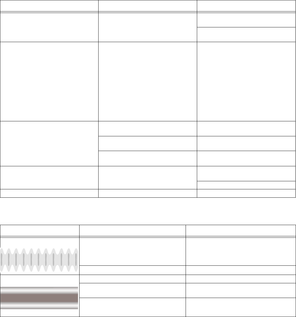
Problem Cause Solution
Spray pattern is pulsating:
Operator is moving too fast while spraying. Slow speed of movement.
Tip or tip filter is clogged. Unclog tip or clean tip filter, page 18.
Spray pattern has tails:
Pressure control is too low. Turn up pressure control.
Incorrect tip for application of
material.
Change tip.
Inlet or outlet valves are worn. See Repair manual.
ti15526a
Troubleshooting
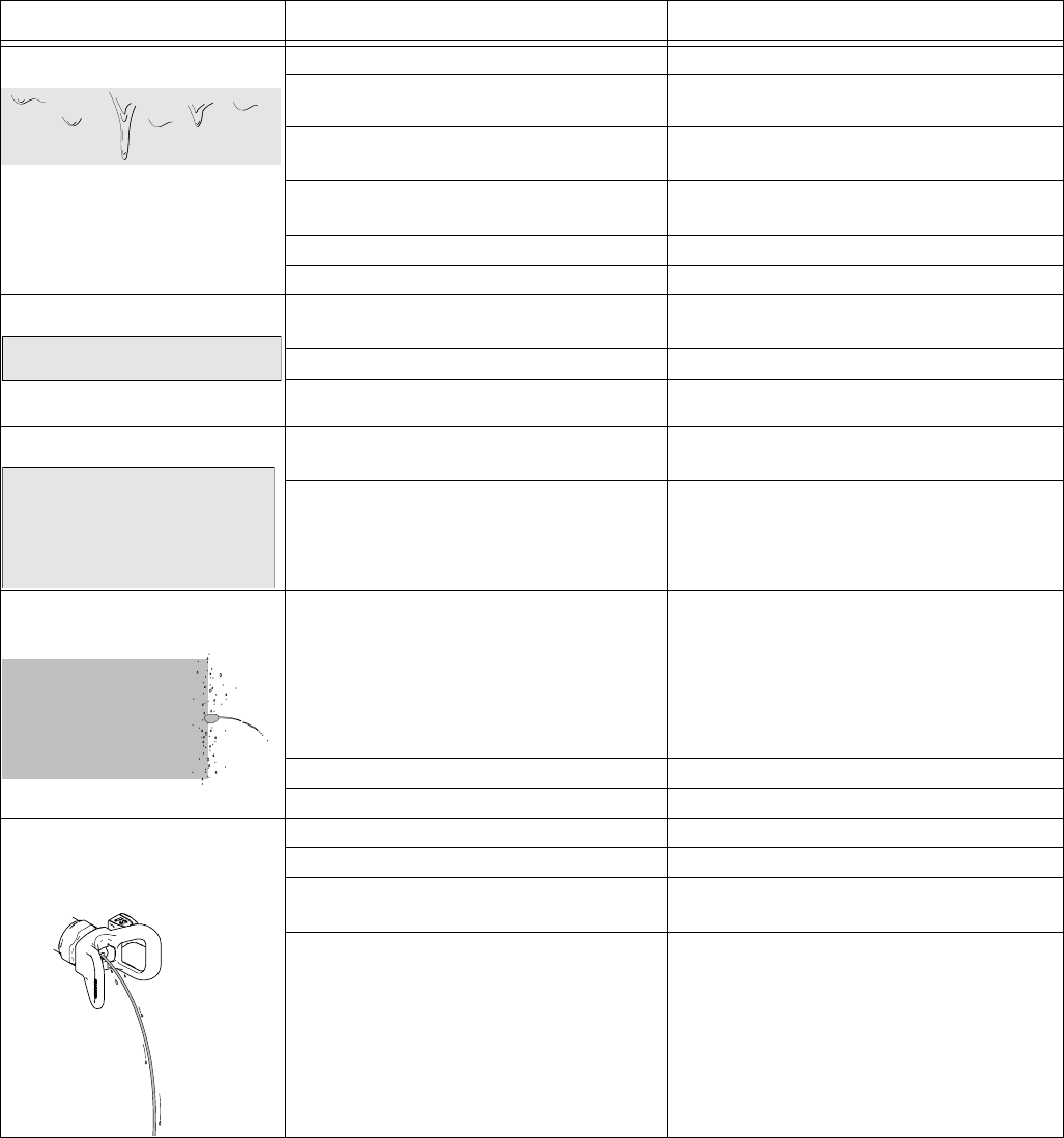
3A2308C 27
Spray pattern has dripping:
Sprayer is moving too slow for material. Move sprayer faster while spraying.
Sprayer is too close to target surface. Move sprayer away from surface 10 in.
(25 cm)
Holding trigger while changing spray
direction.
Release trigger when changing directions.
Incorrect tip for application of
material.
Replace tip.
Pressure control is too high. Turn down pressure control.
Tip is worn or damaged. Replace tip.
Spray pattern is too narrow:
Sprayer is too close to target surface. Move sprayer away from surface 10 in.
(25 cm)
Incorrect tip for application of material. Replace tip.
Tip is worn or damaged. Replace tip.
Spray pattern is too wide:
Sprayer is too far away from target sur-
face.
Move sprayer closer to surface.
Incorrect tip for application of material. Replace tip.
Spray pattern “spits” at the
end or beginning:
Excess material has accumulated on
Spray Tip/Guard Assembly.
See Shutdown and Cleaning, page 19.
Tip filter is partially clogged or damaged. Clean or replace filter. See page 13.
Front valve is slow to react. Clean front valve.
Tip continues to drip or ooze
material after trigger is
released:
Front valve is damaged or worn out. Replace front valve.
Filter is partially clogged or damaged. Clean or replace filter. See page 13.
Tip/Guard Assembly not threaded com-
pletely onto sprayer.
See Install Tip/Guard Assembly, page 14.
Seat is worn. Replace front valve seat housing.
Problem Cause Solution
ti15523a
ti15523a
ti15527a
ti15527a
ti15525a
ti15525a
ti15528a
ti15528a
Repair
28 3A2308C
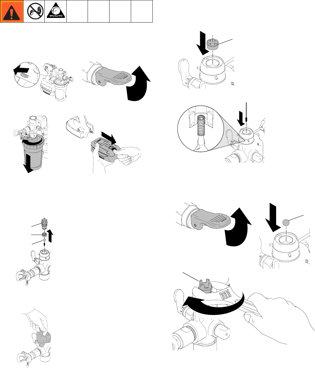
Repair
Inlet Valve
Removal
1. Engage trigger lock and put prime/pressure relief
valve in UP position to relieve pressure.
2. Remove material cup and battery.
3. Hold sprayer upside-down and use wrench or
socket to loosen fitting. Remove inlet fitting (29),
inlet ball (27), spring, and ball guide (25).
NOTE: Use needle-nose pliers to remove spring
and ball guide if needed.
4. Clean as much excess material from inlet cavity as
possible.
Installation
1. Insert ball guide (25) with smaller diameter inserted
first.
2. Use a thin wire to assemble spring into inlet cavity.
3. Make sure prime/pressure relief valve is in UP
position. Insert ball (27) and assemble inlet fitting
(29) using wrench or socket. Tighten to 140 in-lb
(15.8 N•m).
ti19350a ti19347a
ti19360a ti19617a
ti19619a
29
27
25
ti19613a
ti19615a
25
ti19612a
ti19347a
ti19663a
ti19664a
27
29
Repair
3A2308C 29
Outlet Valve
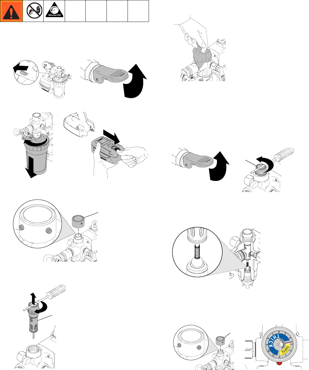
Removal
1. Engage trigger lock and put prime/pressure relief
valve in UP position to relieve pressure.
2. Remove material cup and battery.
3. Loosen set screws (34) from pressure control knob
and remove knob.
4. Use thin screwdriver or allen wrench to turn outlet
valve (31) clockwise and remove.
5. Clean as much excess material from outlet valve
cavity as possible.
Installation
NOTE: Inlet valve must be fully installed before outlet
valve can be installed.
1. Make sure prime/pressure relief valve is in UP posi-
tion. Use a thin screwdriver or allen wrench and turn
outlet valve (31) counter-clockwise to install.
2. Thread outlet valve in until it touches inlet ball.
DO NOT TIGHTEN. Outlet valve should only be
threaded until inlet ball does not move when
touched.
3. Install pressure control knob. Turn knob fully
counter-clockwise until it stops (“0” setting will line
up with red dot). Torque set screws (34) to 40 in-lb
(4.5 N•m).
ti19350a ti19347a
ti19360a ti19617a
ti19620a
34
ti19626a
31
ti19614a
ti19347a
ti19623a
31
ti19616a
ti19620a ti19351a
34
Repair
30 3A2308C
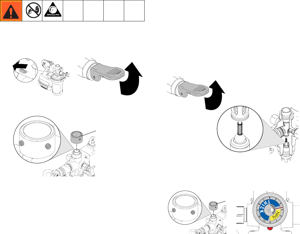
Pressure Control Knob
Removal
1. Engage trigger lock and put prime/pressure relief
valve in UP position to relieve pressure.
2. Loosen two set screws (34) from pressure control
knob and remove knob.
Installation
NOTE: Inlet valve must be fully installed before outlet
valve can be installed.
1. Make sure prime/pressure relief valve is in UP posi-
tion. Use a thin screwdriver or allen wrench to turn
outlet valve counter-clockwise until it touches inlet
ball. DO NOT TIGHTEN. Outlet valve should only
be threaded until inlet ball does not move when
touched.
2. Install pressure control knob. Turn knob fully coun-
ter-clockwise (“0” setting will line up with red dot).
Torque set screws (34) to 40 in-lb (4.5 N•m).
ti19350a ti19347a
ti19620a
34
ti19347a
ti19616a
ti19351a
ti19620a
34
Repair
3A2308C 31
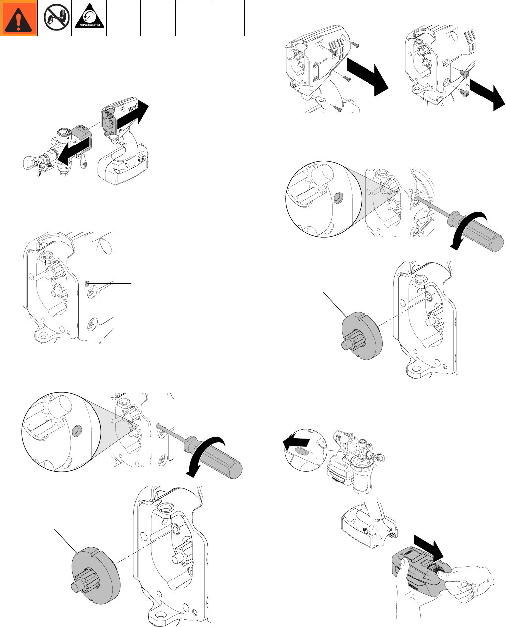
Pump Module/Drive Module
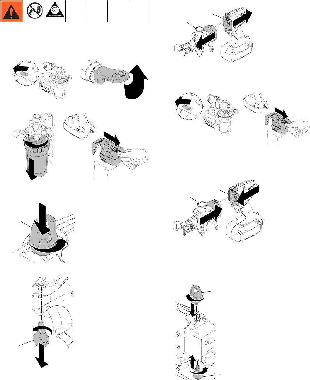
Removal
1. Engage trigger lock and put prime/pressure relief
valve in UP position to relieve pressure.
2. Remove material cup and battery.
3. Unscrew swivel bolt (22) by pressing down and
turning it counter-clockwise. Use tool if needed.
4. Unscrew bolt (20). Use tool if needed.
5. Remove pump module (35) from drive module (11).
Installation
1. Engage trigger lock and remove battery from unit.
2. Assemble pump module (35) to drive module (11).
Gears must properly engage for assembly. Slightly
rotate pump assembly as needed for proper
engagement.
3. Assemble swivel bolt (22) and bolt (20). Partially
thread both bolts before tightening either bolt. Use
tool to tighten and make sure bolts are secure.
NOTE: Make sure there is no gap between the two
housings when assembling bolts.
ti19350a ti19347a
ti19360a ti19617a
ti19621a
22
ti19618a
20
ti19625a
35
11
ti19350a
ti19617a
ti19624a
35
11
ti19622a
22
20
Repair
32 3A2308C
Pump Rebuild Kit
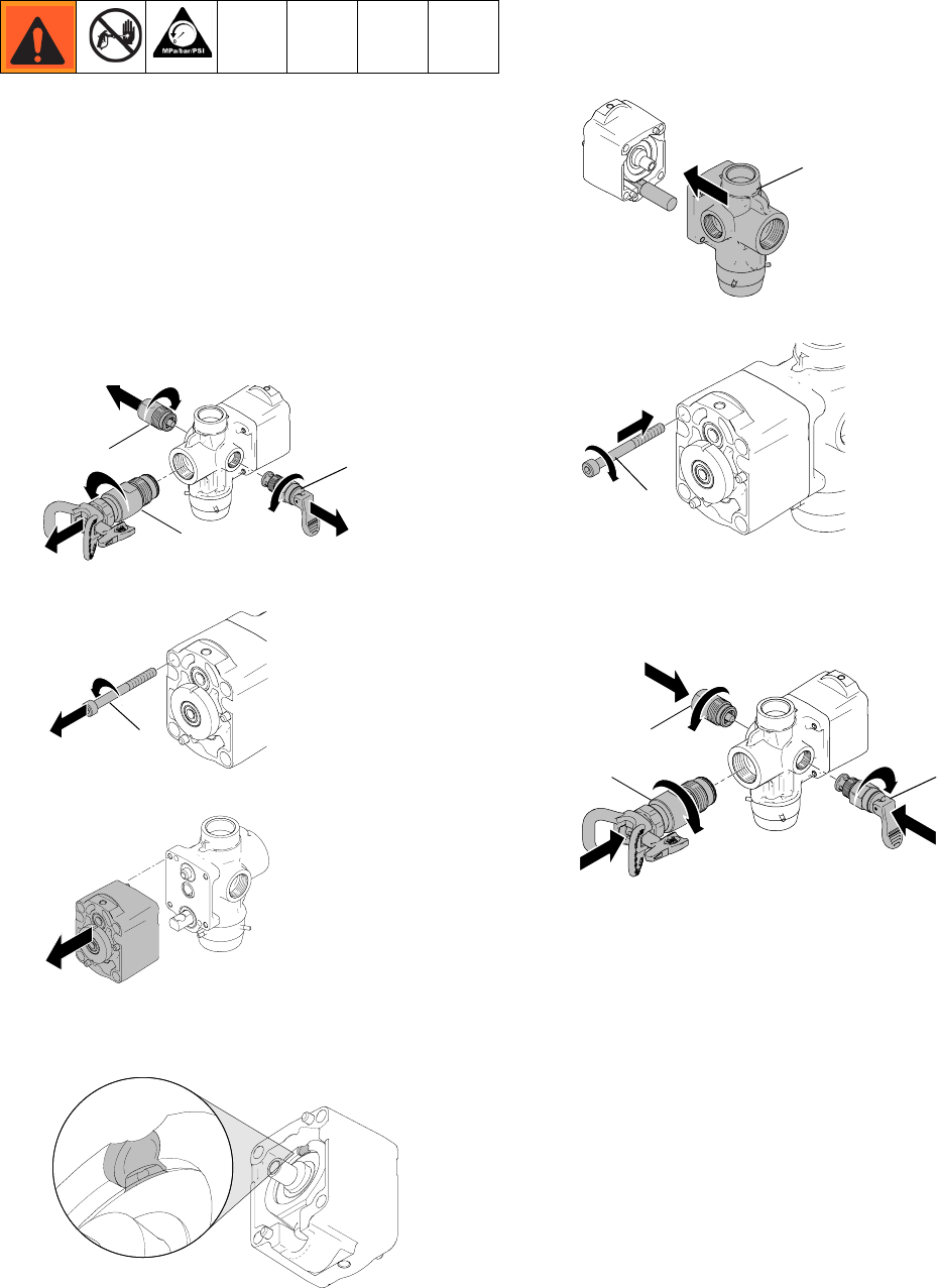
Removal
1. Remove pump module from drive module. See
Pump Module/Drive Module, page 31.
2. Remove outlet valve from pump module and set
aside. See Outlet Valve, page 29.
3. Remove inlet valve from pump module and set
aside. See Inlet Valve, page 7.
4. Remove accumulator (16), front valve (18), and
prime valve (17) from pump module and set aside.
5. Remove four bolts (21) from pump module.
6. Separate pump portions as shown below.
7. Inspect wobble drive assembly. If bearing race is
visible as shown below, replace wobble drive
assembly.
Installation
1. Hold rebuild kit (15) and insert wobble drive into pis-
ton pocket and connect together.
2. Install four bolts (21). Torque to 60 in-lb (6.7 N•m).
3. Install accumulator (16). Torque to 140 in-lb
(15.8 N•m). Apply thread sealant to prime valve (17)
and install. Torque to 140 in-lb (15.8 N•m). Install
front valve (18) fully tighten.
4. Install inlet valve to pump module. See Inlet Valve,
page 7.
5. Install outlet valve to pump module. See Outlet
Valve, page 29.
6. Install pump module to drive module. See Pump
Module/Drive Module, page 31.
ti19645a
16 17
18
ti19646a
21
ti19647a
ti19863a
ti19642a
15
ti19643a
21
ti19644a
16
17
18
Repair
3A2308C 33
Clamshell
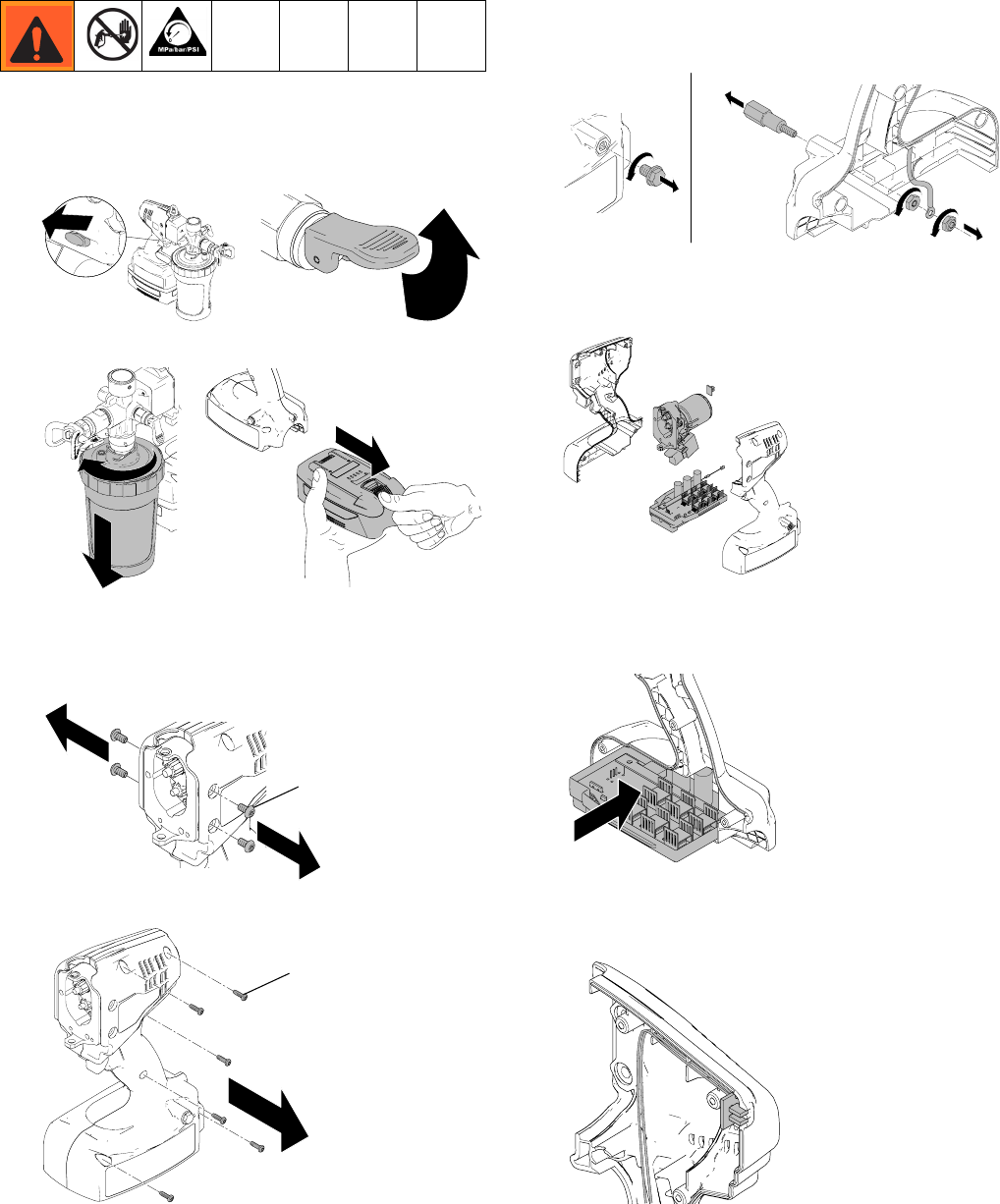
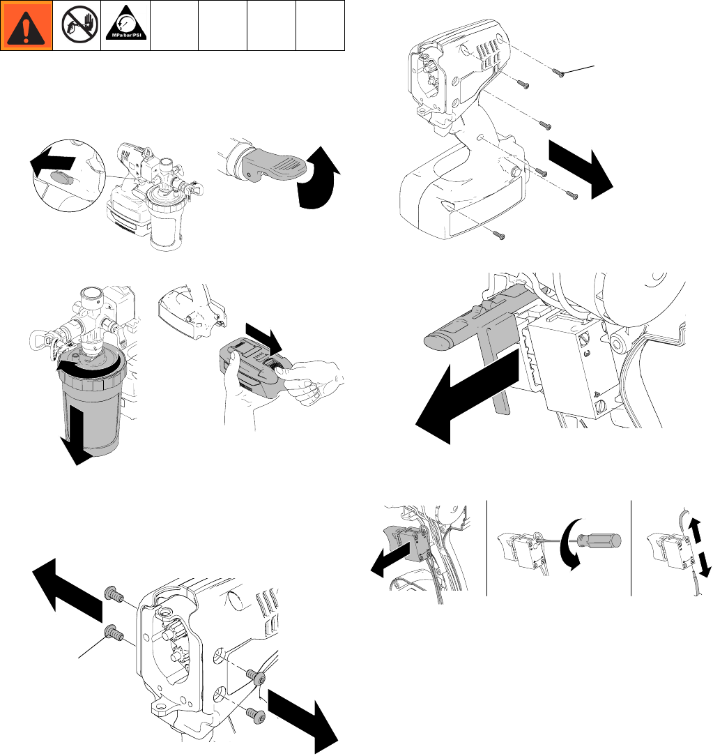
Removal
1. Engage trigger lock and put prime/pressure relief
valve in UP position to relieve pressure.
2. Remove material cup and battery.
3. Remove pump module from drive module. See
Pump Module/Drive Module, page 31.
4. Remove screws (42) from motor housing.
5. Remove screws (43) from clamshell.
6. Remove nut from ground stud. Remove ring termi-
nal and unscrew second nut from ground stud.
Remove ground stud from clamshell.
7. Carefully remove motor, motor housing, switch, con-
trol board, indicator lights, trigger lock, and static
wick from clamshell.
Installation
1. Insert control board into right half of clamshell.
2. Install two LED lights into designated slot in right
half of clamshell. Push wire bundle into slots in
clamshell.
ti19350a ti19347a
ti19360a ti19617a
ti19636a
42
ti19637a
43
ti19638a
ti19639a
ti19627a
ti19628a
Repair
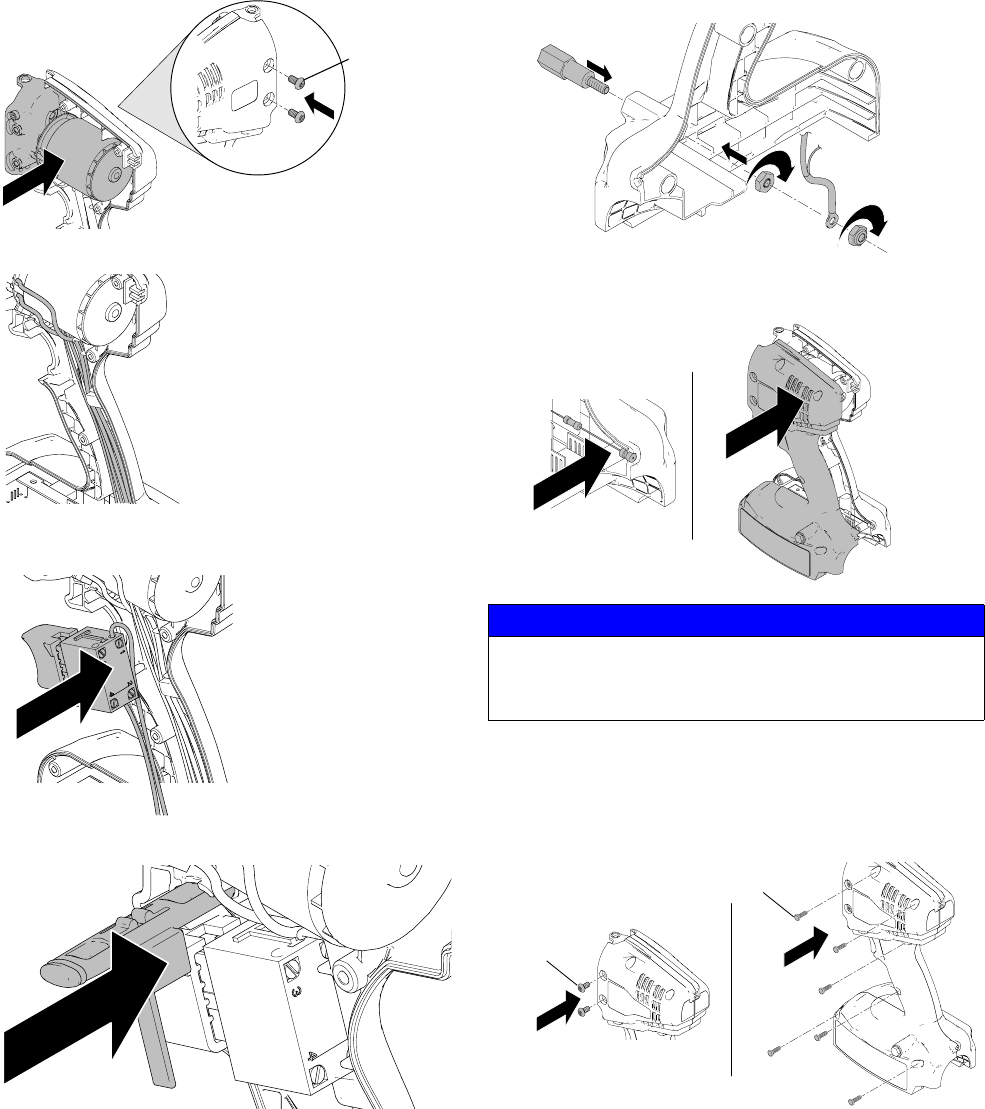
34 3A2308C
3. Set motor housing into right half of clamshell and
loosely install two bolts (42) to motor housing as
shown below.
4. Route wires from motor down the handle.
5. Install trigger over top of wires. Route trigger wires
behind trigger.
6. Insert trigger lock over trigger with o-ring facing out.
7. Press ground stud into left half of clamshell. Tighten
nut onto stud. Install ground terminal to stud and
tighten second nut onto stud. Install wire up along
handle.
8. Insert static wick into right half of clamshell and
install left clamshell to right clamshell.
9. Install bolts (42) to motor housing and install screws
(43) to connect clamshell halves. Make sure LED
lights and static wick are securely in place. Tighten
bolts (42) to 50 in-lb (5.6 N•m) and screws (43)
to 9 in-lb (1 N•m).
10. Install pump module to drive module. See Pump
Module/Drive Module, page 31.
ti19629a
42
ti19630a
ti19631a
ti19632a
NOTICE
Wires can become damaged when pinched between
clamshell halves. Make sure no wires are pinched
during reassembly.
ti19633a
ti19634a
ti19635a
43
42
Repair
3A2308C 35
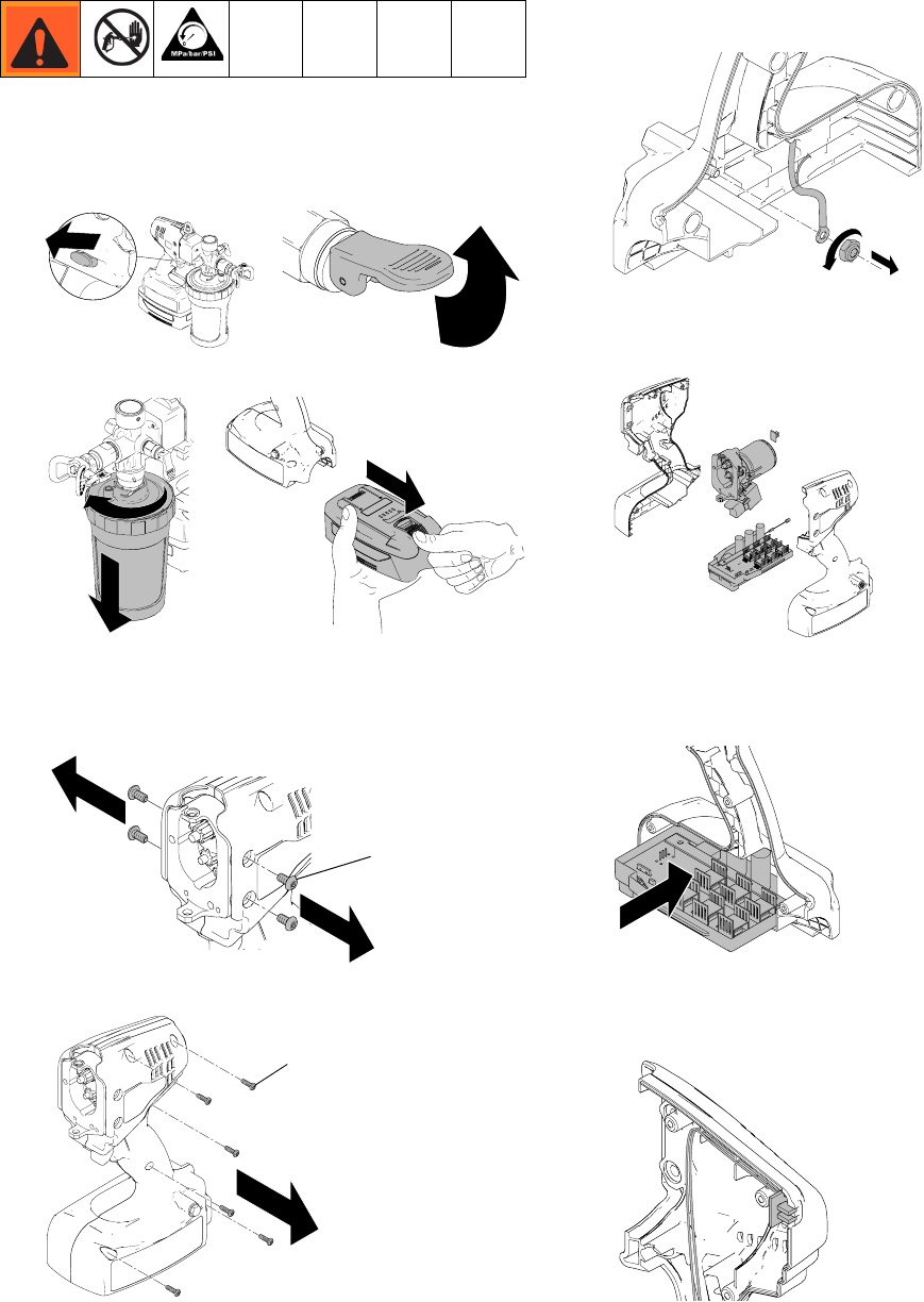
Motor/Control Board Replacement Kit
Removal
1. Engage trigger lock and put prime/pressure relief
valve in UP position to relieve pressure.
2. Remove material cup and battery.
3. Remove pump module from drive module. See
Pump Module/Drive Module, page 31.
4. Remove four bolts (42) from motor housing.
5. Remove screws (43) from clamshell.
6. Unscrew nut from ground stud and remove ring
terminal. Leave other nut secured to ground stud.
7. Remove motor, motor housing, switch, control
board, indicator lights, trigger lock, and static wick
from clamshell.
Installation
1. Insert control board into right half of clamshell.
2. Install two LED lights into designated slot in right
half of clamshell. Push wire bundle into slots in
clamshell.
ti19350a ti19347a
ti19360a ti19617a
ti19636a
42
ti19637a
43
ti19640a
ti19639a
ti19627a
ti19628a
Repair
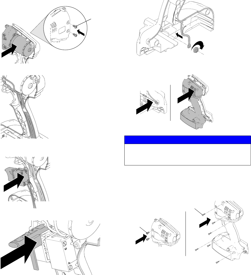
36 3A2308C
3. Set motor housing into right half of clamshell and
loosely install two bolts (42) to motor housing as
shown below.
4. Route wires from motor down the handle.
5. Assemble trigger over top of wires. Route trigger
wires behind trigger.
6. Insert trigger lock over trigger with o-ring facing out.
7. Install ground terminal to stud and tighten second
nut onto stud. Install wire up along handle.
8. Insert static wick into right half of clamshell and
install left clamshell to right clamshell.
9. Install two bolts (42) to motor housing and install
screws (43) to connect clamshell halves. Make sure
LED lights and static wick are securely in place.
Tighten bolts (42) to 50 in-lb (5.6 N•m) and screws
(43) to 9 in-lb (1 N•m).
10. Install pump module into drive module. See Pump
Module/Drive Module, page 31.
ti19629a
42
ti19630a
ti19631a
ti19632a
NOTICE
Wires can become damaged when pinched between
clamshell halves. Make sure no wires are pinched
during reassembly.
ti19641a
ti19634a
ti19635
a
42
43
Repair
3A2308C 37
Switch Assembly
Removal
1. Engage trigger lock and put prime/pressure relief
valve in UP position to relieve pressure.
2. Remove material cup and battery.
3. Remove pump module from drive module. See
Pump Module/Drive Module, page 31.
4. Remove four bolts (42) from motor housing.
5. Remove eight screws (43) from clamshell.
6. Remove trigger lock from assembly.
7. Remove trigger switch from clamshell and loosen
screws connecting wires to switch.
ti19350a
ti19347a
ti19360a
ti19617a
ti19636a
42
ti19637a
43
ti19649a
ti19650a
Repair
38 3A2308C
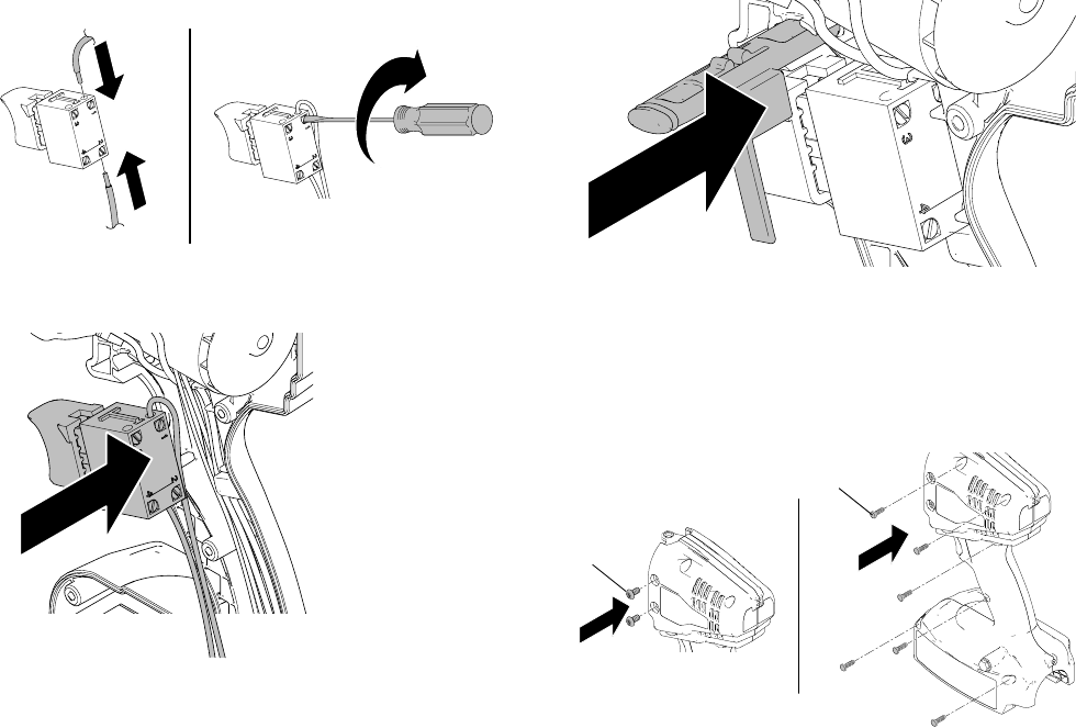
Installation
1. Insert wires and tighten screws to connect wires into
slots 1 and 2 of trigger switch.
2. Install trigger over top of wires. Route trigger wires
behind trigger.
3. Install trigger lock over trigger with o-ring facing out.
4. Install bolts (42) into motor housing and install
screws (43) to connect the clamshell halves. Make
sure LED lights and static wick are properly in place.
Tighten all four bolts (42) to 50 in-lb (5.6 N•m) and
screws (43) to 9 in-lb (1 N•m).
5. Install pump module into drive module. See Pump
Module/Drive Module, page 31.
ti19648a
ti19631a
ti19632a
ti19635a
42
43
Repair
3A2308C 39
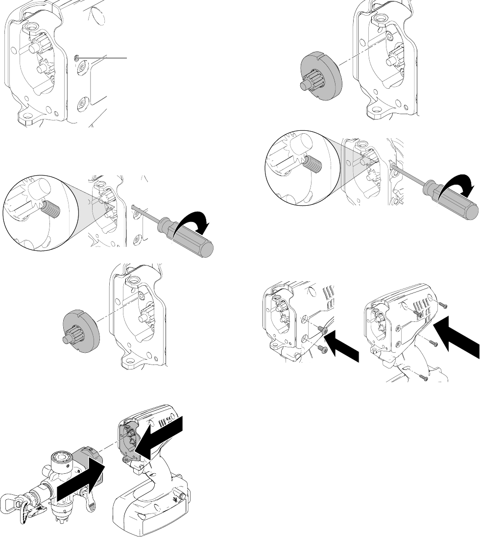
Gear Replacement
Removal
1. Remove pump module from drive module. See
Pump Module/Drive Module, page 31.
2. If unit has accessible retaining bolt shown below,
proceed to step 3. If unit does not have accessible
retaining bolt, proceed to step 4.
3. Unscrew retaining bolt until gear (48) is no longer
retained. Remove gear from drive. Proceed to
Installation.
4. Remove four screws holding clamshells together
and two bolts connecting drive to clamshell.
5. Pull the clamshell up and unscrew retaining bolt
until gear (48) is no longer retained. Remove gear
from drive. Proceed to Installation.
Installation
1. Engage trigger lock and remove battery from unit.
ti19625a
ti19858a
ti19860a
ti19859a
48
ti19861a
ti19877a
ti19860a
ti19878a
48
ti19617a
ti19350a
Repair
40 3A2308C
2. If unit has accessible retaining bolt shown below,
proceed to step 3. If unit does not have accessible
retaining bolt, proceed to step 5.
3. Install new gear into drive housing. Screw retaining
bolt into drive housing to retain gear. Torque to 30
in-lb (3.4 N•m).
4. Install pump module to drive module. See Pump
Module/Drive Module, page 31.
5. Install new gear into drive housing. Pull the clam-
shell up and screw in retaining bolt to retain gear.
Torque to 30 in-lb (3.4 N•m).
6. Install two bolts connecting drive to clamshell.
Torque to 50 in-lb (5.6 N•m). Install four screws
connecting clamshell halves. Torque to 9 in-lb
(1.0 N•m).
7. Install pump module to drive module. See Pump
Module/Drive Module, page 31.
ti19858a
ti19857a
ti19860a
ti19624a
ti19879a
ti19860a
ti19880a
ti19862a

Technical Data
3A2308C 41
Technical Data
FCC Declaration for Battery Charger
This device complies with Part 15 of the FCC Rules. Operation is subject to the following two conditions: (1) this device may not cause harmful
interference, and (2) this device must accept any interference received, including interference that may cause undesired operation.
WARNING:
Changes or modifications to this unit not expressly approved by the party responsible for compliance could void the user’s authority to
operate the equipment.
NOTE:
This equipment has been tested and found to comply with the limits for a Class A digital device, pursuant to Part 15 of the FCC Rules.
These limits are designed to provide reasonable protection against harmful interference in a residential installation. The equipment generates,
uses and can radiate radio frequency energy and, if not installed an used in accordance with the instructions, may cause harmful interference to
radio communications. However, there si no guarantee that interference will not occur in a particular installation. If this equipment does not cause
harmful interference to radio or television reception, which can be determined by turning the equipment off and on, the user is encouraged to try to
correct the interference by one or more of the following measure:
• Reorient or relocate the receiving antenna
• Increase the separation between the equipment and receiver
• Connect the equipment into an outlet on a circuit different from that to which the receiver is connected
• Consult the dealer or an experienced radio/TV technician for help
Models 16H960, 16N654, 16N927, 16N655, 16N656
U.S. Metric
Sprayer:
Adjustable Pressure Range 1000 to 4000 psi 69 to 276 bar, 6.9 to 27.6 MPa
Maximum Working Pressure 4000 psi 276 bar, 26.7 MPa
Weight 8.6 lb 3.9 kg
Dimensions:
Length 14.5 in. 36.8 cm
Width 5.6 in. 14.2 cm
Height 12.8 in. 32.5 cm
Storage Temperature Range ◆❖ 32° to 113° F 0° to 45° C
Operating Temperature Range ✔40° to 90° F 4° to 32° C
Battery Charging Temperature Range 50° to 113° F 10° to 45° C
Storage Humidity Range 0% to 95% relative humidity, non-condensing
Sound Pressure Level LpA = 79.0 dB, Sound Power = LWA = 90.0
Vibration Level Acceleration Less than 8.2 feet/s
2
2.5 m/s
2
††
Wetted Parts Brass, aluminum, 301 sstl, 440c sstl, carbide, FKM, TFE, PTFE, LDPE,
UHMWPE, Polypropylene, Nylon 6/6
Charger:
Charging Time 50 minutes to 80%, 75 minutes to 100%
Power Source 120 VAC / 240 VAC
Battery:
Voltage 28 VDC, Lithium Ion
Capacity 2.4 Ah, 67 Wh
◆
Pump damage will occur if fluid freezes in pump.
❖
Damage to plastic parts may result if impact occurs in low temperature conditions.
✔
Changes in coating viscosity at very low or very high temperatures can affect sprayer performance.
†
per ISO 3744 measured at 3.1 feet (1m)
††
per ISO 5349, no load condition

Notes
42 3A2308C
Notes

Notes
3A2308C 43
Notes

All written and visual data contained in this document reflects the latest product information available at the time of publication.
Graco reserves the right to make changes at any time without notice.
This manual contains English. MM 3A2308
Graco Headquarters: Minneapolis
International Offices: Belgium, China, Japan, Korea
GRACO INC. AND SUBSIDIARIES • P.O. BOX 1441 • MINNEAPOLIS MN 55440-1441 • USA
Copyright 2012, Graco Inc. All Graco manufacturing locations are registered to ISO 9001.
www.graco.com
Revision C - April 2013
Graco Standard Warranty
Graco warrants all equipment referenced in this document which is manufactured by Graco and bearing its name to be free from defects in
material and workmanship on the date of sale to the original purchaser for use. With the exception of any special, extended, or limited warranty
published by Graco, Graco will, for a period of twelve months from the date of sale, repair or replace any part of the equipment determined by
Graco to be defective. This warranty applies only when the equipment is installed, operated and maintained in accordance with Graco’s written
recommendations.
This warranty does not cover, and Graco shall not be liable for general wear and tear, or any malfunction, damage or wear caused by faulty
installation, misapplication, abrasion, corrosion, inadequate or improper maintenance, negligence, accident, tampering, or substitution of
non-Graco component parts. Nor shall Graco be liable for malfunction, damage or wear caused by the incompatibility of Graco equipment with
structures, accessories, equipment or materials not supplied by Graco, or the improper design, manufacture, installation, operation or
maintenance of structures, accessories, equipment or materials not supplied by Graco.
This warranty is conditioned upon the prepaid return of the equipment claimed to be defective to an authorized Graco distributor for verification of
the claimed defect. If the claimed defect is verified, Graco will repair or replace free of charge any defective parts. The equipment will be returned
to the original purchaser transportation prepaid. If inspection of the equipment does not disclose any defect in material or workmanship, repairs
will be made at a reasonable charge, which charges may include the costs of parts, labor, and transportation.
THIS WARRANTY IS EXCLUSIVE, AND IS IN LIEU OF ANY OTHER WARRANTIES, EXPRESS OR IMPLIED, INCLUDING BUT NOT LIMITED
TO WARRANTY OF MERCHANTABILITY OR WARRANTY OF FITNESS FOR A PARTICULAR PURPOSE
.
Graco’s sole obligation and buyer’s sole remedy for any breach of warranty shall be as set forth above. The buyer agrees that no other remedy
(including, but not limited to, incidental or consequential damages for lost profits, lost sales, injury to person or property, or any other incidental or
consequential loss) shall be available. Any action for breach of warranty must be brought within two (2) years of the date of sale.
GRACO MAKES NO WARRANTY, AND DISCLAIMS ALL IMPLIED WARRANTIES OF MERCHANTABILITY AND FITNESS FOR A
PARTICULAR PURPOSE, IN CONNECTION WITH ACCESSORIES, EQUIPMENT, MATERIALS OR COMPONENTS SOLD BUT NOT
MANUFACTURED BY GRACO
. These items sold, but not manufactured by Graco (such as electric motors, switches, hose, etc.), are subject to
the warranty, if any, of their manufacturer. Graco will provide purchaser with reasonable assistance in making any claim for breach of these
warranties.
In no event will Graco be liable for indirect, incidental, special or consequential damages resulting from Graco supplying equipment hereunder, or
the furnishing, performance, or use of any products or other goods sold hereto, whether due to a breach of contract, breach of warranty, the
negligence of Graco, or otherwise.
Graco Information
For the latest information about Graco products, visit www.graco.com.
TO PLACE AN ORDER, contact your Graco distributor or call 1-800-690-2894 to identify the nearest distributor.
