Graco 3A2497Bpro Xp 60 Aa Wb And Wb3000 Users Manual 3A2497B, Instructions Parts For Pro Electrostatic Air Assisted Waterborne Spray Gun Isolation Encl
2015-04-02
: Graco Graco-3A2497Bpro-Xp-60-Aa-Wb-And-Wb3000-Users-Manual-686002 graco-3a2497bpro-xp-60-aa-wb-and-wb3000-users-manual-686002 graco pdf
Open the PDF directly: View PDF ![]() .
.
Page Count: 78
- toc
- Contents
- Models
- Warnings
- Gun Overview
- Installation
- Gun Setup
- Operation
- Maintenance
- Electrical Tests
- Troubleshooting
- Repair
- Prepare the Gun for Service
- Air Cap, Spray Tip, and Fluid Seat Housing Replacement
- Electrode Replacement
- Gun Barrel Removal
- Gun Barrel Installation
- Fluid Needle Replacement
- Power Supply Removal and Replacement
- Alternator Removal and Replacement
- Fan Air Adjustment Valve Repair
- Atomizing Air Adjustment Valve Repair
- ES On-Off Valve Repair
- Air Valve Repair
- Smart Module Replacement
- Air Swivel and Exhaust Valve Replacement
- Parts
- Spray Tip Selection Chart
- Repair Kits, Related Manuals, and Accessories
- Gun Accessories
- Dimensions
- Technical Data
- Graco Pro Xp Warranty
- Contents
- tables
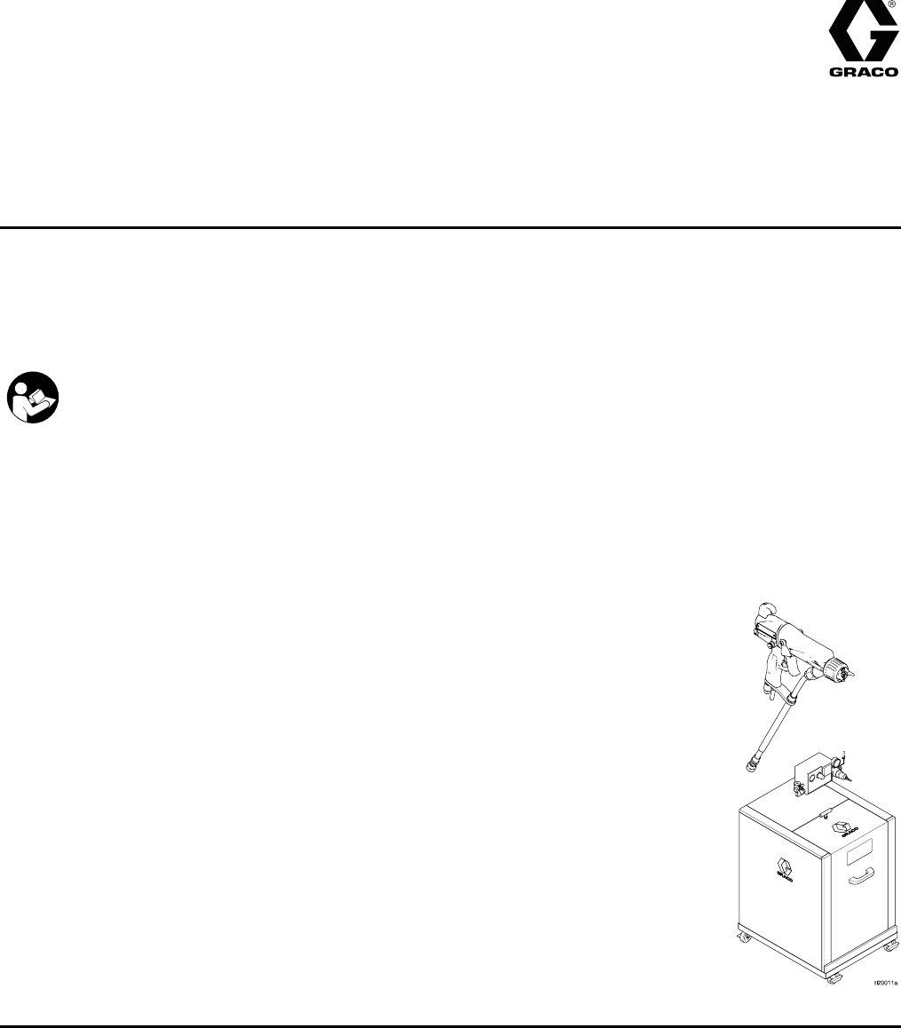
Instructions - Parts
WB3000 Isolation System &
Pro Xp™ 60 AA WB Gun 3A2497B
EN
Air-assisted spray system for use when electrostatically spraying conductive, waterborne fluids that
meet at least one of the conditions for non-flammability listed on page 3.
For professional use only.
Important Safety Instructions
Read all warnings and instructions in this manual. Save these
instructions.
3000 psi (21 MPa, 210 bar) Maximum
Fluid Working Pressure
100 psi (0.7 MPa, 7 bar) Maximum
Air Working Pressure
See page 3 for model part numbers
and approval information.
PROVEN QUALITY. LEADING TECHNOLOGY.
Contents
Models............................................................... 3
Warnings ........................................................... 4
Gun Overview .................................................... 7
How the Electrostatic AA Spray Gun
Works ............................................ 7
Spraying Waterborne Fluids
Electrostatically .............................. 7
Controls, Indicators, and Components........... 8
Smart Guns ................................................. 9
Installation.......................................................... 15
System Requirements .................................. 15
Warning Sign............................................... 15
Install the System......................................... 15
Ventilate the Spray Booth ............................. 15
Air Supply Line ............................................ 16
Ground the Cabinet...................................... 16
Connect the Waterborne Fluid Hose.............. 17
Agitator Kit Accessory .................................. 20
Gun Setup.......................................................... 21
Grounding ................................................... 21
Check Gun Electrical Grounding ................... 23
Flush Before Using Equipment...................... 24
Operation........................................................... 25
Operating Checklist...................................... 25
Fluid Voltage Discharge and Grounding
Procedure ...................................... 25
Pressure Relief Procedure............................ 26
Fill the Fluid Supply...................................... 27
Adjust the Spray Pattern............................... 28
Shutdown .................................................... 30
Maintenance ...................................................... 31
Flushing ...................................................... 31
Clean the Gun Daily ..................................... 33
Daily System Care ....................................... 35
Electrical Tests................................................... 36
Test Gun Resistance.................................... 36
Test Power Supply Resistance ..................... 37
Test Gun Barrel Resistance.......................... 38
Test Ground Strip Resistance ....................... 39
Test Cylinder Resistance.............................. 39
Troubleshooting.................................................. 40
Voltage Loss Troubleshooting....................... 40
Spray Pattern Troubleshooting...................... 43
Gun Operation Troubleshooting .................... 44
Electrical Troubleshooting ............................ 45
Repair................................................................ 47
Prepare the Gun for Service ......................... 47
Air Cap, Spray Tip, and Fluid Seat Housing
Replacement.................................. 48
Electrode Replacement ................................ 49
Gun Barrel Removal..................................... 50
Gun Barrel Installation.................................. 50
Fluid Needle Replacement............................ 51
Power Supply Removal and
Replacement.................................. 52
Alternator Removal and Replacement ........... 53
Fan Air Adjustment Valve Repair .................. 55
Atomizing Air Adjustment Valve
Repair............................................ 55
ES On-Off Valve Repair ............................... 56
Air Valve Repair........................................... 57
Smart Module Replacement.......................... 58
Air Swivel and Exhaust Valve
Replacement.................................. 59
Parts.................................................................. 60
Standard Air-Assisted Spray Gun
Assembly ....................................... 60
Smart Air-Assisted Spray Gun
Assembly ....................................... 62
Isolation Enclosure....................................... 64
Alternator Assembly ..................................... 67
ES On-Off Valve Assembly........................... 68
Fan Air Valve Assembly ............................... 69
Air Cap Assembly ........................................ 70
Smart Module Assembly............................... 70
Spray Tip Selection Chart.................................... 71
AEM Fine Finish Spray Tips.......................... 71
AEF Fine Finish Pre-Orifice Spray
Tips ............................................... 72
Repair Kits, Related Manuals, and
Accessories .......................................... 73
Gun Accessories.......................................... 73
Operator Accessories................................... 73
System Accessories..................................... 73
Hoses ......................................................... 74
Test Equipment ........................................... 74
245895 Agitator Kit ...................................... 75
Dimensions ........................................................ 76
Technical Data ...................................................77
Graco Pro Xp Warranty....................................... 78
23A2497B

Models
Models
Models which are FM Approved and Compliant with EN50059
FM approved for use with fluids that meet the following condition:
• Material does not sustain burning in accordance with the Standard Test Method
for Sustained Burning of Liquid Mixtures, ASTM D4206.
0.35 J, with
24M508 Hose
FM12ATEX0080
EN 50059
Ta 0°C – 50°C
Models Compliant with EN 50059 when used
with fluids that meet the following criteria:
• Materials which cannot be ignited, in any mixture with air, by an energy source
of less than 500 mJ.
Part No. Model Description
24N551 WB3000 Waterborne Isolation Enclosure 24N550 with standard
electrostatic air-assisted spray gun H60T18, grounded air hose
235070, and unshielded waterborne fluid hose 24M508.
24P632 WB3000 Waterborne Isolation Enclosure 24N550 with smart electrostatic
air-assisted spray gun H60M18, grounded air hose 235070,
and unshielded waterborne fluid hose 24M508.
24N550 WB3000 Waterborne Isolation Enclosure for unshielded hoses. Does not
include hoses and gun.
H60T18 ProXp60AAWB Standard Electrostatic Air-assisted Spray Gun, for waterborne
coatings.
H60M18 ProXp60AAWB Smart Electrostatic Air-assisted Spray Gun, for waterborne
coatings.
24M508 -—— Unshielded Waterborne Fluid Hose Assembly, 25 ft (7.6 m).
3A2497B 3

Warnings
Warnings
The following warnings are for the setup, use, grounding, maintenance and repair of this equipment. The
exclamation point symbol alerts you to a general warning and the hazard symbol refers to procedure-specific
risks. When these symbols appear in the body of this manual or on warning labels, refer backtothese
Warnings. Product-specific hazard symbols and warnings not covered in this section may appear throughout
the body of this manual where applicable.
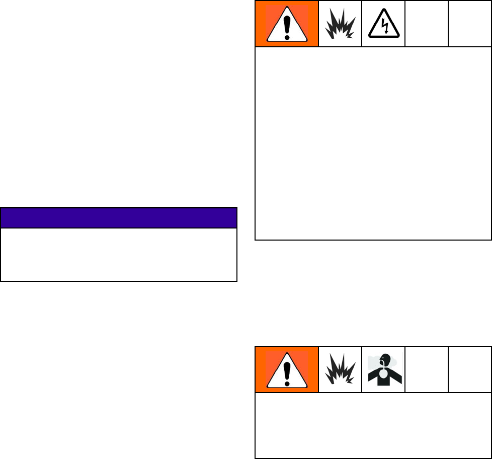
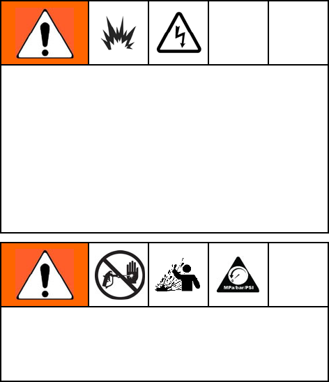
WARNING
ELECTRIC SHOCK HAZARD
Improper grounding, setup, or usage of an isolated waterborne system can result in electric
shock. To help prevent electric shock:
• Ground all equipment, personnel, object being sprayed, and conductive objects in or close
to spray area. See Grounding instructions.
• Connect the electrostatic gun to a voltage isolation system that will discharge the system
voltage when not in use.
•Allcompo
nents of the isolation system that are charged to high voltage must be contained
within an isolation enclosure that prevents personnel from making contact with thehigh
voltage components before the system voltage is discharged.
• Follow the Fluid Voltage Discharge and Grounding Procedure when instructed to discharge
the voltage; before cleaning, flushing, or servicing the system; before approaching the front of
the gun; and before opening the isolation enclosure for the isolated fluid supply.
• Do not enter a high voltage or hazardous area until all high voltage equipment has been
discharged.
•Donott
ouch the gun nozzle or electrode, or come within 4 in. (102 mm) of the electrode
during gun operation. Follow the Fluid Voltage Discharge and Grounding Procedure.
• Interlock the gun air supply with the voltage isolation system to shut off the air supply anytime
the isolation system enclosure is opened.
• Only use the red-colored Graco electrically conductive gun air hose with this gun. Do not
use black or gray-colored Graco air hoses.
• Do not splice hoses together. Install only one continuous Graco waterborne fluid hose
between the isolated fluid supply and the spray gun.
43A2497B
Warnings
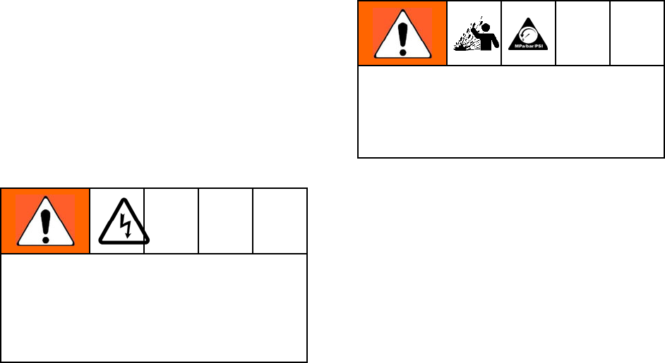
WARNING
FIRE AND EXPLOSION HAZARD
Combustible dust in work area canigniteorexplode.Tohelppreventfireandexplosion:
• Fluids used must meet the following flammability requirements:
•FM, FMc Approved:
Material does not sustain burning in accordance with the Standard Test Method for
Sustained Burning of Liquid Mixtures, ASTM D4206.
•CE-EN 50059 Compliant:
Materials which cannot be ignited, in any mixture with air, by an energy source of
less than 500mJ.
•Stop operation immediately if static sparking occurs or you feel a shock. Do not use
equipment until you identify and correct the problem.
• Check gun resistance, hose resistance, and electrical grounding daily.
• Use and clean equipment only in well ventilated area.
• Interlock the gun air supply to prevent operation unless ventilating fansareon.
•Onlyusen
on-flammable solvents when flushing or cleaning equipment.
• Always turn the electrostatics off when flushing, cleaning or servicing equipment.
• Eliminate all ignition sources; such as pilot lights, cigarettes, portable electric lamps, and
plastic drop cloths (potential static arc).
• Do not plug or unplug power cords or turn lights on or off when flammable fumes are present.
• Keep spray area free of debris, including solvent, rags and gasoline.
• Keep a working fire extinguisher in the work area.
SKIN INJECTION HAZARD
High-pressure fluid from gun, hose leaks, or ruptured components will pierce skin.Thismay
look like just a cut, but it is a serious injury that can result in amputation. Get immediate surgical
treatment.
• Do not spray without tip guard and trigger guard installed.
• Engage trigger lock when not spraying.
• Do not point gun at anyone or at any part of the body.
• Do not put your hand over the spray tip.
•Dono
t stop or deflect leaks with your hand, body, glove, or rag.
• Follow the Pressure Relief Procedure when you stop spraying and before cleaning, checking,
or servicing equipment.
• Tighten all fluid connections before operating the equipment.
• Check hoses and couplings daily. Replace worn or damaged parts immediately.
PLASTIC PARTS CLEANING SOLVENT HAZARD
Many solvents can degrade plastic parts and cause them to fail, which could cause serious
injury or property damage.
•Us
e only compatible water-based solvents to clean plastic structural or pressure-containing
parts.
•SeeTechnical Data in this and all other equipment instruction manuals. Read fluid and
solvent manufacturer’s MSDSs and recommendations.
3A2497B 5
Warnings
WARNING
TOXIC FLUID OR FUMES
Toxic fluids or fumes can cause serious injury or death if splashed in the eyesoronskin,
inhaled, or swallowed.
•ReadMSDSsto
know the specific hazards of the fluids you are using.
• Store hazardous fluid in approved containers, and dispose of it according to applicable
guidelines.
PERSONAL PROTECTIVE EQUIPMENT
Wear appropriate protective equipment when in the work area to help prevent serious injury,
including eye injury, hearing loss, inhalation of toxic fumes, and burns. This protective
equipment includes but is not limited to:
• Protective eyewear, and hearing protection.
• Respirators, protective clothing, and gloves as recommended by the fluid and solvent
manufacturer.
EQUIPMENT MISUSE HAZARD
Misuse can cause death or serious injury.
• Do not operate the unit when fatigued or under the influence of drugs or alcohol.
• Do not exceed the maximum working pressure or temperature rating of the lowest rated
system component. See Technical Data in all equipment manuals.
• Use fluids and solvents that are compatible with equipment wetted parts. See Technical Data
in all equipment manuals. Read fluid and solvent manufacturer’s warnings. For complete
information about your material, request MSDS from distributor or retailer.
• Do not leave the work area while equipment is energized or under pressure.
•Turnof
f all equipment and follow the Pressure Relief Procedure when equipment is not in use.
• Check equipment daily. Repair or replace worn or damaged parts immediately with genuine
manufacturer’s replacement parts only.
• Do not alter or modify equipment. Alterations or modifications may void agency approvals
and create safety hazards.
•Makes
ure all equipment is rated and approved for the environment in which you are using it.
• Use equipment only for its intended purpose. Call your distributor for information.
• Route hoses and cables away from traffic areas, sharp edges, moving parts, and hot surfaces.
•Dono
t kink or over bend hoses or use hoses to pull equipment.
• Keep children and animals away from work area.
• Comply with all applicable safety regulations.
63A2497B

Gun Overview
Gun Overview
How the Electrostatic AA Spray Gun
Works
This is not an air spray gun. To help prevent
serious injury from pressurized fluid, such as skin
injection, and splashing fluid, read and follow the
Skin Injection Hazard Warnings on page 5.
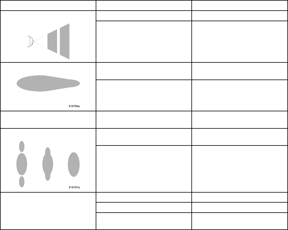
The air-assisted spray gun combines airless and
air spraying concepts. The spray tip atomizes
and shapes the fluid into a fan pattern, as does
a conventional airless spray tip. Air from the air
cap further atomizes the fluid and completes the
atomization of the fluid tails to produce a uniform
pattern.
As the gun is triggered, part of the regulated air
operates the alternator turbine and the rest of the
air helps atomize the fluid being sprayed. The
alternator generates power, which is converted by
the power cartridge to supply high voltage to the
gun’s electrode.
The gun’s internal power supply provides high
voltage. The fluid is electrostatically charged as it
passes the electrode. The charged fluid is attracted
to the grounded workpiece, wrapping around and
evenly coating all surfaces.
The regulated air that is directed to the air cap can
be further controlled using the gun’s atomizing air
adjustment valve. This valve can be used to restrict
air flow to the air cap while maintaining sufficient air
flow to the alternator. The atomizing air adjustment
valve does not control pattern width. To change
pattern width, use a new tip size, or use the fan
adjustment to narrow the pattern width.
The high working fluid pressure of this gun provides
the power needed to atomize higher solids materials.
NOTE: For airless atomization, if desired, turn the
gun’s atomizing air adjustment valve completely off.
Closing this valve does not affect alternator operation.
Spraying Waterborne Fluids
Electrostatically
This electrostatic air-assisted spray gun is designed
to spray onlywaterborne fluids which meet the
following flammability requirements:
•FM, FMc Approved:
Material does not sustain burning in accordance
with the Standard Test Method for Sustained
Burning of Liquid Mixtures, ASTM D4206.
•CE-EN 50059 Compliant:
Materials which cannot be ignited, in any mixture
with air, by an energy source of less than 500mJ.
When connected to a voltage isolation system,
all of the fluid in the spray gun, fluid hose, and
isolated fluid supply is charged to high voltage,
which means that the system has more electrical
energy than a solvent-based system. Therefore,
only non-flammable fluids (as defined under
Models, page 3 ) can be sprayed with the system or
be used to clean, flush, or purge the system.
Precautions must be taken when using electrostatic
waterborne equipment to avoid potential shock
hazards. When the spray gun charges the isolated
fluid to high voltage, it is similar to charging a
capacitor or a battery. The system will store some of
the energy while spraying and retain some of that
energy after the spray gun is shut off. Do not touch
the gun nozzle or come within 4 in. (102 mm) of
the electrode until the stored energy is discharged.
The amount of time it takes to discharge the
energy depends on the system design. Follow the
Fluid Voltage Discharge and Grounding Procedure,
page 25 before approaching the front of the gun.
The Graco warranty and approvals are void if the
electrostatic spray gun is connected to a non-Graco
voltage isolation system or if the gun is operated
above 60 kV.
3A2497B 7
Gun Overview
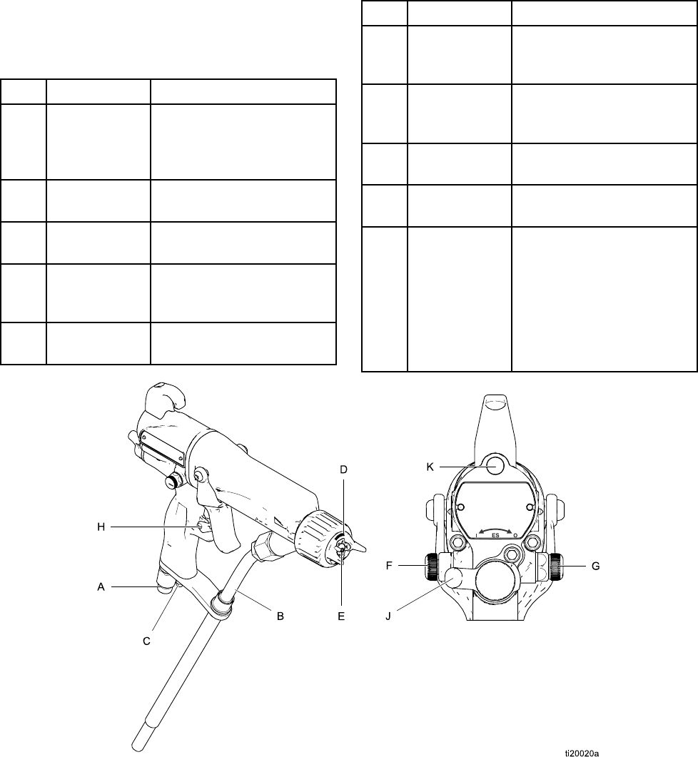
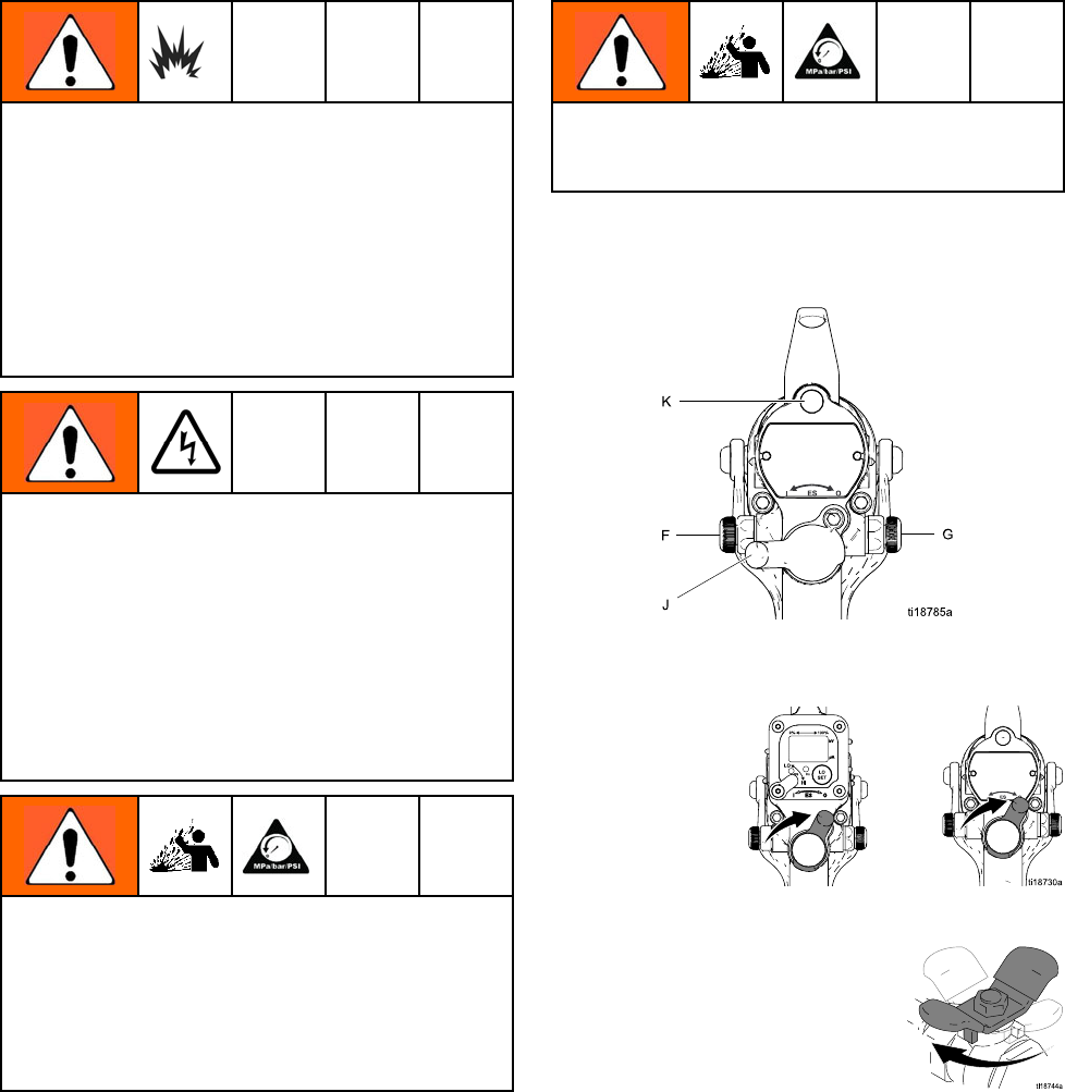
Controls, Indicators, and Components
The electrostatic gun includes the following
controls, indicators, and components (see Fig.
1). For information on Smart guns, also see
Smart Guns, page 9 .
Item Description Purpose
AAir Swivel
Inlet
1/4 npsm(m) left-hand
thread, for Graco
red-colored grounded
air supply hose.
B Fluid Hose Graco waterborne fluid
hose
CTurbine Air
Exhaust
Barbed fitting, for supplied
exhaust tube.
DAir Cap/Tip
Guard and
Spray Tip
See Spray Tip Selection
Chart, page 71, for avail-
able sizes.
EElectrode Supplies electrostatic
charge to the fluid.
Item Description Purpose
FFanAir
Adjustment
Valve
Adjusts fan size and shape.
Canbeusedtodecrease
pattern width.
GAtomizing Air
Adjustment
Valve
Adjusts atomizing air flow.
HTrigger Safety
Lock
Locks trigger to prevent
gun from spraying.
JES On-Off
Valve
Turns electrostatics ON (I)
or OFF (O).
KES Indica-
tor (standard
gun only; for
Smart gun in-
dicator, see
Operating
Mode, page
9)
Lit when ES is ON (I).
Color indicates alternator
frequency. See the LED
indicator table on page 30.
Figure 1 Gun Overview
83A2497B
Gun Overview
Smart Guns
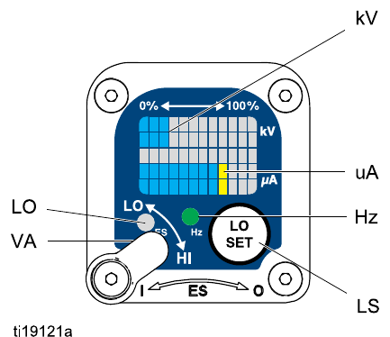
The Smart Gun module displays spraying voltage,
current, alternator speed, and the voltage setting (low
or high). It also allows the user to change to a lower
spraying voltage. The module has two modes:
• Operating Mode
• Diagnostic Mode
Operating Mode
Bar Graph
See Fig. 2, and Table 1 on page 11. The Operating
Mode displays gun data during normal spraying. The
display uses a bar graph to show the voltage level in
kiloVolts (kV) and the current level in microAmperes
(uA). The bar graph range is from 0 to 100% for each
value.
If the uA bar graph LEDs are blue, the gun is ready
to spray. If the LEDs are yellow or red, the current is
too high. See Electrical Troubleshooting, page 45.
Hz Indicator
The Hz indicator functions the same as the ES
indicator on standard guns. The indicator lights to
show the alternator speed status, and has three
colors:
• Green indicates the alternator speed is correct.
• If the indicator changes to amber after 1 second,
increase the air pressure.
• If the indicator changes to red after 1 second,
reduce the air pressure.
Voltage Adjustment Switch
The voltage adjustment switch (VA) allows the
operator to change from low to high voltage.
• The high voltage setting is determined by the
maximum voltage of the gun and is not adjustable.
•Thelowvolt
age indicator (LO) lights
when the switch is set to LO. The low
voltage setting is user adjustable. See
Adjusting the Low Voltage Setting, page 10.
NOTE: If the Error display appears, the Smart module
has lost communication with the power supply. See
Error Display, page 10 for further information.
Figure2 SmartGunModuleinOperatingMode
3A2497B 9
Gun Overview
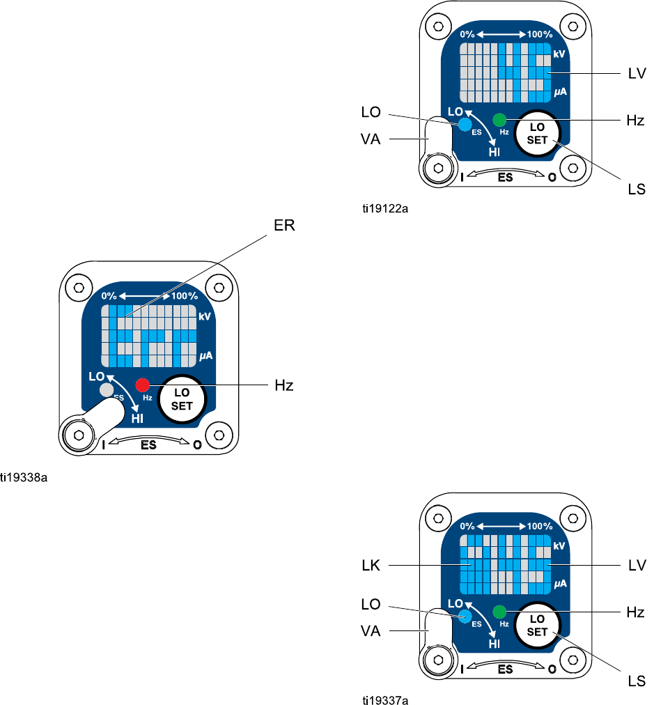
Error Display
If the Smart module loses communication with
the power supply, the Error display appears, the
Hz indicator turns red, and the Smart module is
disabled. See Fig. 3, and Table 1 on page 11.
This can occur in Operating Mode or Diagnostic
Mode. See Electrical Troubleshooting, page 45.
Communication must be restored to make the Smart
module functional.
NOTE: It takes 8 seconds for the Error display to
appear. If the gun has been disassembled, wait 8
seconds before spraying to ensure that an Error
condition has not occurred.
NOTE: If there is no power to the gun, the Error
display will not appear.
Figure3 ErrorDisplay
Adjusting the Low Voltage Setting
The low voltage setting is user adjustable. To access
the low voltage setting screen when in Operating
Mode, press the LO SET button (LS) momentarily.
The screen will display the current low voltage
setting. SeeFig. 4,andTable1onpage11. The
range is 30–60 kV.
Set the Voltage Adjustment switch (VA) to LO. Press
the LO SET button repeatedly to increase the setting
in increments of 5. When the display reaches the
maximum setting (60 kV) it will return to the minimum
setting (30 kV). Continue pressing the button until
you reach the desired setting.
NOTE: After 2 seconds of inactivity the display will
return to the Operating Screen.
NOTE: The low voltage setting may be locked. See
Lock Symbol, page 10.
Figure 4 Low Voltage Setting Screen (Unlocked)
Lock Symbol
The low voltage setting may be locked. When locked,
an image (LK) appears on the screen. See Fig. 5,
and Table 1 on page 11.
• When in HI mode, the low voltage setting is always
locked. The lock symbol will appear when the LO
SET button is pressed.
• When in LO mode, the lock symbol will
only appear if the lock is enabled. See
Low Voltage Lock Screen, page 14,tolockor
unlock the low voltage setting.
Figure 5 Low Voltage Setting Screen (Locked)
10 3A2497B

Gun Overview
Table 1 . Key for Figs. 2–9.
Item Description Purpose
VA Voltage Adjustment Switch Two-position switch sets smart
gun voltage to low setting (LO) or
high setting (HI). This switch is
functional in Operating Mode and
in Diagnostic Mode.
LO Low Voltage Mode Indicator Lights (blue) when the smart gun
is set to Low Voltage.
kV Voltage (kV) Display Displays actual spraying voltage
of the gun, in kV. In Operating
Mode, display is a bar graph.
In Diagnostic Mode, voltage is
displayed as a number.
uA Current (uA) Display Displays actual spraying current
of the gun, in uA. In Operating
Mode, display is a bar graph.
In Diagnostic Mode, current is
displayed as a number.
LS LO SET button Press momentarily to enter the
Low Voltage Setting screen.
Press and hold for approximately 5
seconds to enter or exit Diagnostic
Mode.
While in Diagnostic Mode, press
momentarily to advance through
screens.
While on the Low Voltage Lock
Screen (in Diagnostic Mode),
press and hold to turn the lock on
or off.
LV Low Voltage Display Displays the low voltage setting
as a number. The setting can be
changed. See Fig. 4.
LK Low Voltage Locked Appears if the low voltage setting
is locked. See Fig. 5 and Fig. 9.
LD Lo Display Appears on the Low Voltage Lock
Screen. See Fig. 9.
ER Error Display Appears if the Smart module loses
communication with the power
supply. See Fig. 3.
VI Voltage Indicator In Diagnostic Mode, the two top
right LEDs of the screen light,
indicating that the value displayed
isinkV.SeeFig. 6.
3A2497B 11

Gun Overview
Item Description Purpose
CI Current Indicator In Diagnostic Mode, the two
bottom right LEDs of the screen
light, indicating that the value
displayedisinuA.SeeFig. 7.
AS Alternator Speed Display In Diagnostic Mode, Hz level is
displayed as a number. See Fig.
8.
Hz Alternator Speed Indicator In Operating Mode, indicator color
varies to show the alternator
speed status:
• green indicates the alternator
speed is at the correct level.
• If the indicator changes to amber
after 1 second, the alternator
speed is too low.
• If the indicator changes to red
after 1 second, the alternator
speed is too high. The indicator
will also turn red if the Error
display appears.
In Diagnostic Mode, the indicator
is green when in the Alternator
Speed (Hertz) screen.
123A2497B
Gun Overview
Diagnostic Mode
Diagnostic Mode includes four screens which display
gun data:
• Voltage (kiloVolts) Screen
• Current (microAmperes) Screen
• Alternator Speed (Hertz) Screen
• Low Voltage Lock Screen
NOTE: You must be in Operating Mode to adjust the
low voltage setting; the setting is not adjustable in
Diagnostic Mode. However, the voltage adjustment
switch (VA) can be set to HI or LO in Operating Mode
and Diagnostic Mode.
To enter Diagnostic Mode, press and hold the LO SET
(LS) button for approximately 5 seconds. The display
will go to the Voltage (kiloVolts) Screen, page 13.
To advance to the next screen, press the LO SET
button again.
To exit Diagnostic Mode, press and hold the LO SET
button for approximately 5 seconds. The screen will
return to Operating Mode.
NOTE: If the gun is detriggered while in Diagnostic
Mode,thelastscreenviewedwillbedisplayedwhen
the gun is retriggered.
NOTE: Diagnostic Mode cannot be exited
from the Low Voltage Lock Screen. See
Low Voltage Lock Screen, page 14 for details.
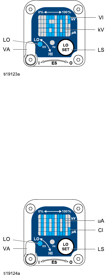
Voltage (kiloVolts) Screen
The Voltage (kiloVolts) Screen is the first screen to
appear after entering Diagnostic Mode. See Fig. 6,
and Table 1 on page 11. To enter this screen, press
and hold the LO SET button for approximately 5
seconds while in the Operating Mode.
This screen displays the spraying voltage of the
gun as a number (kV), rounded to the nearest 5 kV.
The two top right LEDs (VI) of the display panel
light, indicating that the Voltage (kiloVolts) Screen
is displayed. The display is a readout and cannot
be changed.
Press the LO SET button to advance to the
Current (microAmperes) Screen, page 13.Press
and hold for approximately 5 seconds to return to
Operating Mode.
Figure 6 Voltage (kiloVolts) Screen
Current (microAmperes) Screen
The Current (microAmperes) Screen is the second
screen in the Diagnostic Mode. See Fig. 7, and Table
1 on page 11. To enter this screen, press the LO
SET button while in the Voltage (kiloVolts) Screen.
This screen displays the spraying current of the gun
as a number (uA), rounded to the nearest 5 uA. The
two bottom right LEDs (CI) of the display panel light,
indicating that the Current (microAmperes) Screen
is displayed. The display is a readout and cannot
be changed.
Press the LO SET button to advance to the
Alternator Speed (Hertz) Screen, page 14.Press
and hold for approximately 5 seconds to return to
Operating Mode.
Figure 7 Current (microAmperes) Screen
3A2497B 13
Gun Overview
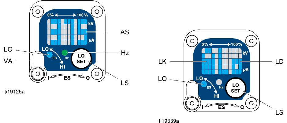
Alternator Speed (Hertz) Screen
The Alternator Speed (Hertz) Screen is the third
screen in the Diagnostic Mode. See Fig. 8, and Table
1 on page 11. To enter this screen, press the LO SET
button while in the Current (microAmperes) Screen.
This screen displays the alternator speed as a 3
digit number (AS), rounded to the nearest 5 Hz. The
display is a readout and cannot be changed. If the
alternator speed is greater than 999 Hz, the display
will show 999.
The Hz indicator lights green to show that you are
viewing the Alternator Speed (Hertz) Screen.
Press the LO SET button to advance to the
Low Voltage Lock Screen, page 14. Press and hold
for approximately 5 seconds to return to Operating
Mode.
Figure 8 Alternator Speed (Hertz) Screen
Low Voltage Lock Screen
The Low Voltage Lock Screen is the fourth screen in
the Diagnostic Mode. See Fig. 9, and Table 1 on
page 11. To enter this screen, press the LO SET
button while in the Alternator Speed (Hertz) Screen.
This screen displays the status of the Low Voltage
Lock. If the setting is locked, the lock image (LK)
appears to the left of the Lo display (LD). If the setting
is unlocked, the lock image does not appear.
To change the lock status, press and hold the
LO SET button until the lock image appears or
disappears. If the lock is set, the image will also
appear on the Low Voltage Setting Screen when in
low voltage mode (see Fig. 4).
NOTE: Diagnostic Mode cannot be exited from this
screen, because pressing and holding the LO SET
button is used to turn the lock on or off. To exit,
press LO SET momentarily to return to the Voltage
(kiloVolts) Screen, then exit Diagnostic Mode from
there.
Figure 9 Low Voltage Lock Screen
143A2497B
Installation
Installation
System Requirements
AGracovolta
ge isolation system must have the
following features:
• An isolation enclosure that prevents persons from
making contact with the high voltage components
before the system voltage is discharged. All
components of the isolation system that are
charged to high voltage must be contained within
the enclosure.
• A bleed resistor to drain off the system voltage
when the spray gun is not in use. A metal part of
the fluid supply unit must be electrically connected
to the bleed resistor.
• A safety interlock that automatically discharges the
system voltage when anyone opens the isolation
enclosure.
NOTICE
The system should not have any severe arcing
occurring when the isolation mechanism opens
and closes. Severe arcing will shorten the life of
the system components.
NOTE: The Graco warranty and approvals are
void if the electrostatic spray gun is connected to a
non-Graco voltage isolation system or if the gun is
operated above 60 kV.
Warning Sign
Mount warning signs in the spray area where they
can easily be seen and read by all operators. An
English Warning Sign is provided with the gun.
Install the System
Installing and servicing this equipment requires
access to parts which may cause electric shock
or other serious injury if work is not performed
properly.
• Do not install or service this equipment unless
you are trained and qualified.
• Be sure your installation complies with local,
state, and national codes for the installation
of electrical apparatus in a Class I, Div. I
Hazardous Location or Group II, Zone I
Explosive Atmosphere Location.
• Comply with all applicable local, state, and
national fire, electrical, and other safety
regulations.
Fig. 12 shows a typical electrostatic air-assisted
spray system. It is not an actual system design.
For assistance in designing a system to suit your
particular needs, contact your Graco distributor.
Ventilate the Spray Booth
Provide fresh air ventilation to reduce the risk of fire
or explosion caused by the buildup of flammable or
toxic vapors when spraying, flushing, or cleaning
the gun. Do not operate the gun unless ventilation
fans are operating.
Check and follow all local, state, and national codes
regarding air exhaust velocity requirements.
High velocity air exhaust will decrease the operating
efficiency of the electrostatic system. The minimum
allowable air exhaust velocity is 60 linear ft/min (18.3
linear meters/minute).
3A2497B 15
Installation
Air Supply Line
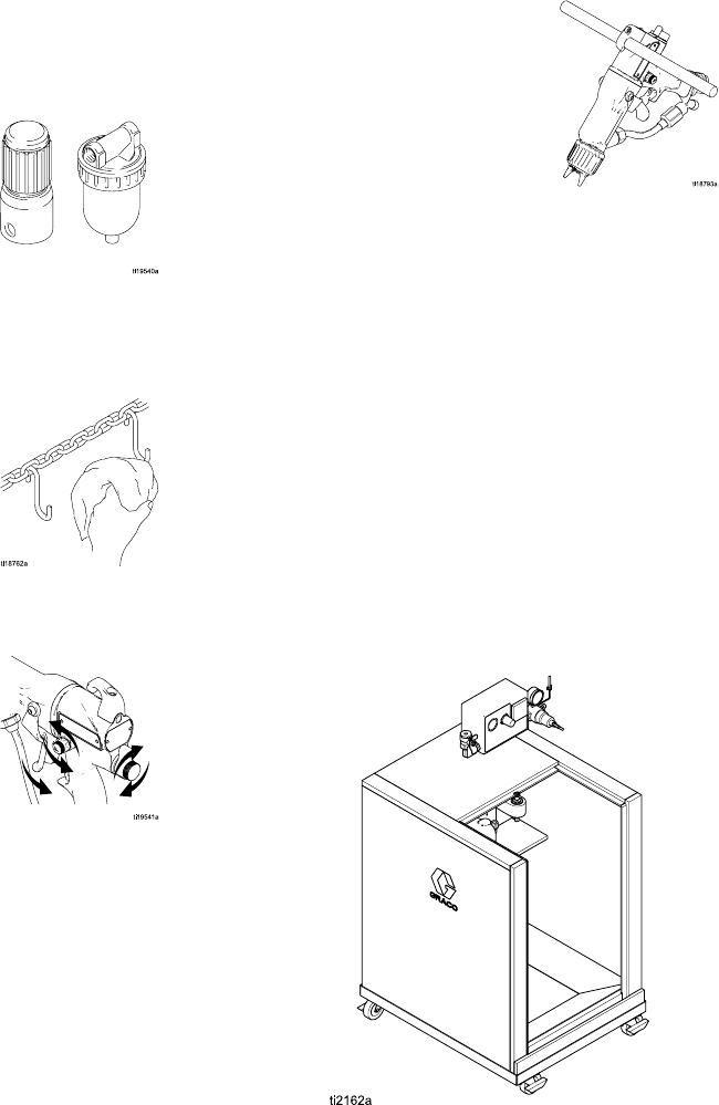
1. See Fig. 12. Install an air line filter/water
separator (M) on the main air supply line to
ensure a dry, clean air supply to the gun. Dirt and
moisture can ruin the appearance of your finished
workpiece and can cause the gun to malfunction.
2. The WB3000 system includes a bleed-type air
regulator (N) on the gun air supply line (P), to
control air pressure to the gun.
To reduce the risk of electric shock or other
serious injury, you must use the red-colored
Graco Electrically Conductive Air Hose for the
gun air supply, and you must connect the hose
ground wire to a true earth ground. Do not use
the black or gray-colored Graco air hoses.
3. Connect the red-colored Graco Electrically
Conductive Air Hose (P) between the gun air
regulator (N) and the gun’s air inlet. The gun air
inlet fitting has a left-hand thread. Connect the
airsupplyhosegroundwire(Q)toatrueearth
ground.
Trapped air can cause the fluid supply unit to
cycle unexpectedly, which can result in serious
injury, including splashing fluid in the eyes or
on the skin. Do not operate the equipment
without the bleed-type air valve (B) installed.
4. The WB3000 system includes a bleed-type air
valve (B). The bleed-type air valve is required
to shut off all air to the system and relieve air
trapped between the valve and the fluid supply
unit after the air regulator is shut off. Connect the
main air supply line (A) to the bleed valve.
5. Install an additional bleed-type air valve (CC)
upstream of the air filter (M) to isolate the filter
for servicing.
Ground the Cabinet
Connect the main ground wire (V) to a true earth
ground.
16 3A2497B
Installation
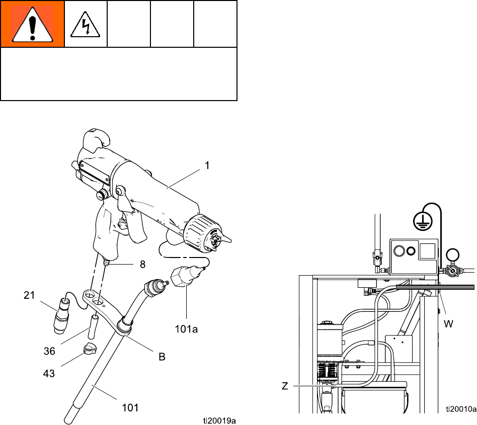
Connect the Waterborne Fluid Hose
Always use a Graco waterborne fluid hose between
the voltage isolation system fluid outlet and the gun
fluid inlet.
Before connecting the waterborne fluid hose to the
gun, blow it out with air and flush with water to
remove contaminants. Flush the gun before using it.
To reduce the risk of electric shock, install only
one continuous Graco waterborne hose between
the isolated fluid supply and the gun. Do not splice
hoses together.
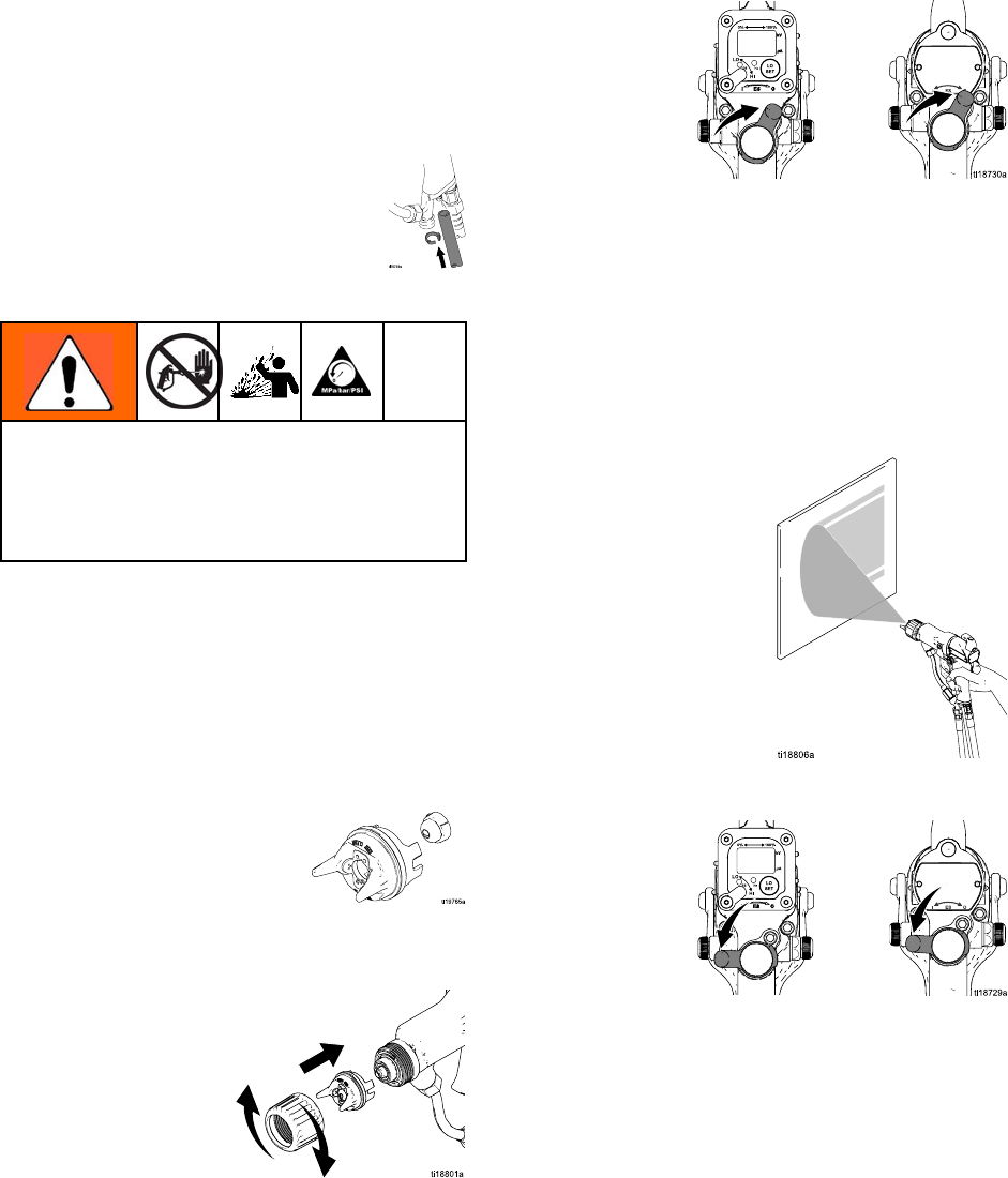
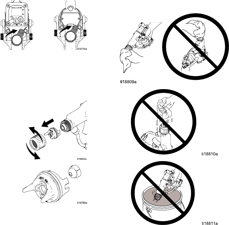
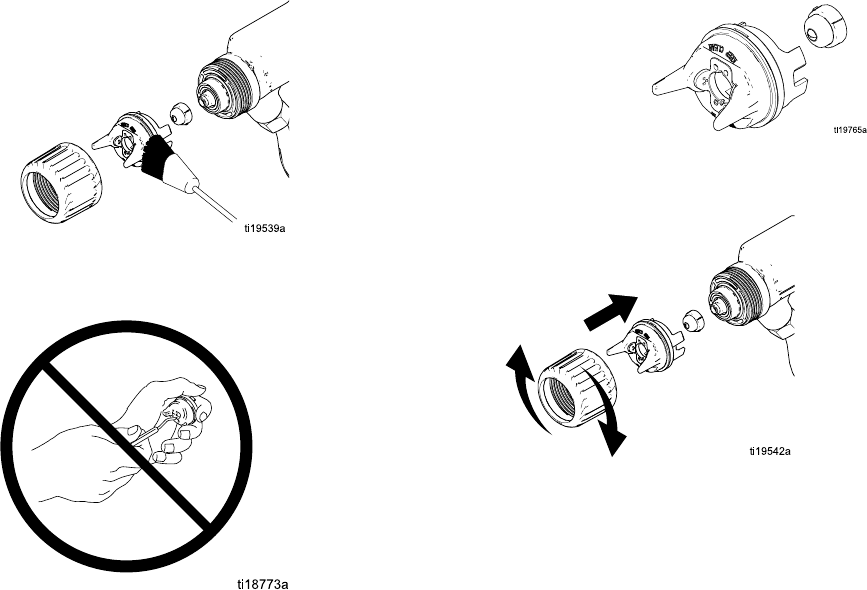
1. Remove the gun air inlet fitting (21).
Figure 10 Connect the Fluid Hose
2. Make sure the barrel fluid inlet is clean and dry.
Apply dielectric grease to the threads of the barrel
connector (101a) and screw it into the fluid inlet.
3. Apply dielectric grease to the threads of the
hose (101) and screw it into the barrel connector
(101a).
4. Align the bracket (B) holes with the air inlet and
exhaust outlet. Secure with the air inlet fitting
(21).
5. Press the exhaust tube (35) onto the exhaust
valve. Secure with the clamp (36).
6. Slide the other end of the hose through the hole
in the side of the isolated enclosure. Connect the
swivel (Z) to the fluid outlet of the pump. Secure
thehosetothesideoftheenclosurewiththe
bracket (W).
NOTE: The Graco warranty and approvals are
void if the electrostatic spray gun is connected
to a non-Graco voltage isolation system or if the
gun is operated above 60 kV.
Figure 11 Unshielded Hose 24M508 Connection at
WB3000 Enclosure
3A2497B 17
Installation
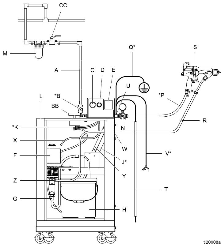
Figure 12 Typical Installation, Pro Xp Waterborne
System
18 3A2497B

Installation
Typical Installation Key
Item Description
AMain Air Supply Line
B* Bleed-Type Air Shutoff
Valve
CPump Air Pressure
Gauge
D Pump Air Pressure
Regulator
E kV Meter
FPump
GPumpSuct
ion Hose
HPaint Container
J* Bleed Resistor
K* Enclosure Safety
Interlock
L Isolated Enclosure
MGun Air Line Filter
NGun Air Pressure
Regulator
P* Graco Red Grounded
Air Hose (left-hand
threads)
Q* Gun Air Hose Ground
Wire
RGraco Waterborne Fluid
Hose
Item Description
SWaterborne
Electrostatic
Air-Assisted Spray
Gun
TGrounding Rod
UGround Terminal
V* Main Ground Wire
WStrain Relief Fitting
XPump Air Supply Line
YGrounding Cylinder
ZPump Fluid Outlet
Fitting
AA Isolated Enclosure Door
(not shown, to illustrate
internal components.
Door must be closed
and locked to operate
system).
BB Enclosure T-Handle
Locking Screw (part of
door assembly)
CC Accessory Bleed-Type
Air Shutoff Valve
* These items are required for safe operation. They
are included with the WB3000 system.
3A2497B 19
Installation
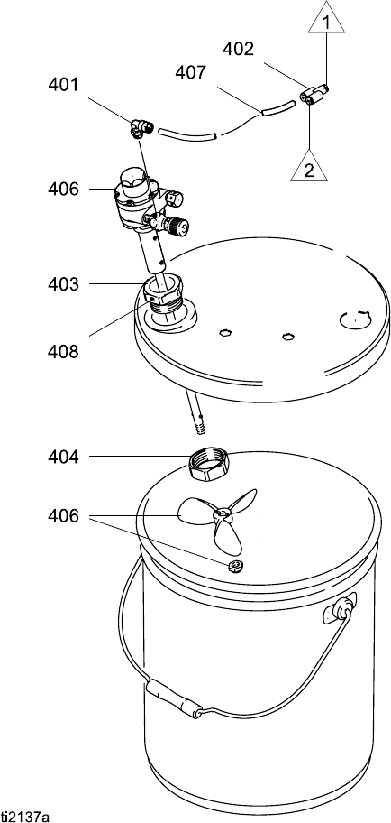
Agitator Kit Accessory
To add an agitator to the Graco isolation system, order
Part No. 245895. See 245895 Agitator Kit, page 75,
for the kit parts list.
1. Discharge the system voltage (see Fluid Voltage
Discharge and Grounding Procedure, page 25).
2. Relieve the pressure (see
Pressure Relief Procedure, page 26).
3. Open the isolated enclosure door.
4. Remove the back of the control box (258).
5. Remove tube (A2) from elbow (282) at the air
manifold; see . Install the Y fitting (402) into
the elbow. Install tubes (A2) and (407) into the
Y fitting. Route the agitator tube (407) into the
cabinet.
6. Replace the back of the control box (258).
7. Assemble the other parts of the kit as shown.
Secure the agitator with the setscrew (408).
8. Return the system to service.
Figure 13 245895 Agitator Kit
20 3A2497B
Gun Setup
Gun Setup
Grounding
When operating the electrostatic gun, any
ungrounded objects in the spray area (people,
containers, tools, etc.) can become electrically
charged. Improper grounding can result in static
sparking, which can cause a fire, explosion, or
electric shock. Ground all equipment, personnel,
object being sprayed, and conductive objects
in or close to the spray area. Resistance must
not exceed 100 ohms. Follow the grounding
instructions below.
The following are minimum grounding requirements
for a basic electrostatic waterborne system. Your
system may include other equipment or objects which
must be grounded. Check your local electrical code
for detailed grounding instructions. Your system must
be connected to a true earth ground.
•
Voltage Isolation System:
Electrically connect the
voltage isolation system to a true earth ground.
See Ground the Cabinet, page 16.
•
Electrostatic Air-Assisted Spray Gun:
ground
the gun by connecting the red-colored Graco
Grounded Air Hose to the gun, and connecting the
air hose ground wire to a true earth ground. See
Check Gun Electrical Grounding, page 23.
•
Object being sprayed:
keep the workpiece hangers
clean and grounded at all times.
•
All electrically conductive objects or devices in the
spray area:
must be properly grounded.
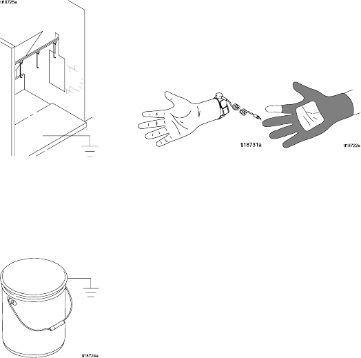
•
Fluid and waste containers:
ground all fluid and
waste containers in the spray area. Do not use pail
liners unless they are conductive and grounded.
When flushing the spray gun, the container used
to catch the excess fluid must be electrically
conductive and grounded.
•
Air compressors:
ground the equipment according
to the manufacturer's recommendations.
•
All air lines
must be properly grounded. Use only
grounded hoses with a maximum of 100 feet (30.5
m) combined hose length to ensure grounding
continuity.
3A2497B 21
Gun Setup
•
The floor of the spray area:
must be electrically
conductive and grounded. Do not cover the floor
with cardboard or any non-conductive material
which would interrupt grounding continuity.
•
All solvent pails:
use only approved, grounded
metal containers, which are conductive. Do not
use plastic containers. Only use non-flammable
solvents. Do not store more than the quantity
needed for one shift.
•
All persons entering the spray area:
must wear
shoes having conductive soles such as leather,
or wear personal grounding straps. Do not
wear shoes with non-conductive soles such as
rubber or plastic. If gloves are necessary, wear
the conductive gloves supplied with the gun. If
non-Graco gloves are worn, cut off fingers or palm
area of gloves to ensure your hand contacts the
grounded gun handle.
223A2497B
Gun Setup
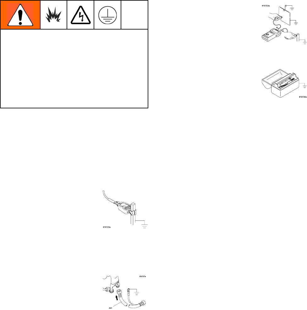
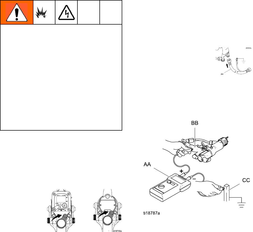
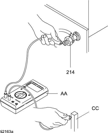
Check Gun Electrical Grounding
Megohmmeter Part No. 241079 (AA-see Fig.
14) is not approved for use in a hazardous area.
To reduce the risk of sparking, do not use the
megohmmeter to check electrical grounding
unless:
• The gun has been removed from the hazardous
area;
• Or all spraying devices in the hazardous area
are turned off, ventilation fans in the hazardous
area are operating, and there are no flammable
vapors in the area (such as open solvent
containers or fumes from spraying).
Failure to follow this warning could cause fire,
explosion, and electric shock and result in serious
injury and property damage.
Graco Part No. 241079 Megohmmeter is available
as an accessory to check that the gun is properly
grounded.
1. Have a qualified electrician check the electrical
grounding continuity of the spray gun and air
hose.
2. Turn OFF (O) the ES On-Off switch.
3. Turn off the air and fluid supply to the gun. Follow
the Pressure Relief Procedure, page 26.
4. Disconnect thefluidhose.
5. Make sure the grounded air hose is connected
and the hose groundwireisconnectedtoatrue
earth ground.
6. Measure the resistance between the gun handle
(BB) and a true earth ground (CC). Use an
applied voltage of 500 minimum to 1000 volts
maximum. The resistance should not exceed
100 ohms. See Fig. 14.
Figure 14 Check Gun Electrical Grounding
3A2497B 23
Gun Setup
7. If the resistance is greater than 100 ohms, check
the tightness of the ground connections and be
suretheairhosegroundwireisconnectedtoa
true earth ground. If the resistance is still too
high, replace the air hose.
8. Using an ohmmeter (AA) measure the resistance
between the cabinet ground lug (214) and a true
earth ground (CC). The resistance must be less
than 100 ohms.
Figure 15 Check Cabinet Grounding
Flush Before Using Equipment
The equipment was tested in fluid at the factory. To
avoid contaminating your fluid, flush the equipment
with a compatible solvent before using the equipment.
243A2497B
Operation
Operation
Operating Checklist
Check the following list daily, before starting the
system.
⃞All operators are properly trained to operate
an electrostatic waterborne air-assisted spray
system as instructed in this manual.
⃞All operators are trained in the
Pressure Relief Procedure, page 26.
⃞The electrostatics are turned off and system
voltage is discharged according to the
Fluid Voltage Discharge and Grounding
Procedure, page 25, before any person en-
ters the isolation enclosure, before cleaning,
and before performing any maintenance or
repair.
⃞The system is grounded according to the
instructions in Grounding, page 21.
⃞The Graco waterborne fluid hose is in good
condition with no cuts or abrasions of the
inner layer. Replace hose if damaged.
⃞Ventilation fans are operating properly.
⃞All debris, including flammable fluids and
rags, is removed from the spray area.
⃞Fluids used must meet the following
flammability requirements:
•FM, FMc Approved:
Material does not sustain burning in
accordance with the Standard Test Method
for Sustained Burning of Liquid Mixtures,
ASTM D4206.
•CE-EN 50059 Compliant:
Materials which cannot be ignited, in any
mixturewithair,byanenergysourceof
less than 500mJ.
Fluid Voltage Discharge and
Grounding Procedure
The fluid supply is charged with high voltage until
the voltage is discharged. Contact with the charged
components of the voltage isolation system or
spray gun electrode will cause an electric shock.
To avoid an electric shock, follow the Fluid Voltage
Discharge and Grounding Procedure:
• whenever you are instructed to discharge the
voltage
• before cleaning, flushing, or servicing the system
equipment
• before approaching the front of the gun
• or before opening the isolation enclosure for the
isolated fluid supply.
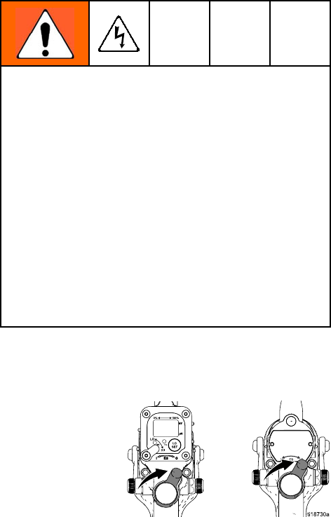
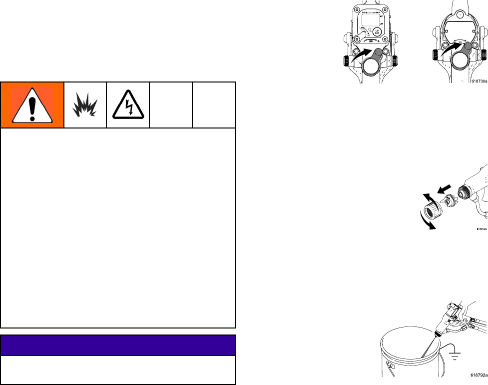
1. Turn the ES ON/OFF valve OFF and wait 30
seconds, to allow the voltage to discharge
through the bleed resistor.
2. Fully unscrew the door T-handle locking screw.
This will shut off the air to the gun and trigger the
grounding cylinder to discharge any remaining
electrical charge.
3. Use the grounding rod to touch the pump
and supply pail. If you see any arcs, see
Electrical Troubleshooting, page 45.
3A2497B 25
Operation
Pressure Relief Procedure
This equipment stays pressurized until pressure
is manually relieved. To help prevent serious
injury from pressurized fluid, such as skin injection,
splashing fluid and moving parts, follow the
Pressure Relief Procedure when you stop spraying
and before cleaning, checking, or servicing the
equipment.
1. Turn OFF (O) the ES On/Off switch.
2. Follow the Fluid Voltage Discharge and
Grounding Procedure, page 25.
3. Engage the trigger lock.
4. Turn off the air bleed valves to the fluid source
and to the gun.
5. Disengage the trigger lock.
6. Trigger the gun into a grounded metal waste
container to relieve the fluid pressure.
7. Engage the trigger lock.
8. Open the pump drain valve, having a waste
container ready to catch the drainage. Leave
thepumpdrainvalveopenuntilyouareready
to spray again.
9. If the spray tip or hose is completely clogged or
pressure is not fully relieved, slowly loosen the
hose end coupling. Now clear the spray tip or
hose.
26 3A2497B

Operation
Fill the Fluid Supply
1. Follow the Fluid Voltage Discharge and
Grounding Procedure, page 25.
2. Follow the Pressure Relief Procedure, page 26.
3. Open the isolated enclosure door.
4. Remove the pail cover from the pail, holding a rag
over the suction tube strainer to prevent any fluid
from dripping into the isolated enclosure. Place
the cover and suction tube outside the enclosure.
5. Remove the supply pail from the enclosure.
NOTICE
Be sure to wipe up all fluid spills in the isolated
enclosure. Fluid can create a conductive path
and cause the system to short out.
6. Clean up any fluid spills in the enclosure, using
a soft cloth and a non-flammable, compatible
solvent.
7. Fill the supply pail with fluid and return it to the
enclosure. Clean up any spills.
8. Reinstall the pail cover, holding a rag over the
suction tube strainer to prevent fluid spills while
you place the pump suction tube in the pail.
9. Close the isolated enclosure door and fasten
securely with the T-handle locking screw.
3A2497B 27
Operation
Adjust the Spray Pattern
To reduce the risk of fire and explosion, fluids used
must meet the following flammability requirements:
•FM, FMc Approved:
Material does not sustain burning in accordance
with the Standard Test Method for Sustained
Burning of Liquid Mixtures, ASTM D4206.
•CE-EN 50059 Compliant:
Materials which cannot be ignited, in any mixture
with air, by an energy source of less than 500mJ.
Contact with the charged components of the spray
gun will cause an electric shock. Do not touch
the gun nozzle or electrode or come within 4 in.
(102 mm) of the electrode during operation or
until performing the Fluid Voltage Discharge and
Grounding Procedure, page 25.
Follow the Fluid Voltage Discharge and Grounding
Procedure, page 25 when you stop spraying and
whenever you are instructed to discharge the
voltage.
To reduce the risk of component rupture, which
can cause serious injury, do not exceed the
maximum working pressure of the lowest rated
system component. This equipment has a 100 psi
(0.7 MPa, 7 bar) maximum air working pressure
and a 3000 psi (21 MPa, 210 bar) maximum fluid
working pressure.
To reduce the risk of an injury, follow the
Pressure Relief Procedure, page 26 whenever you
are instructed to relieve the pressure.
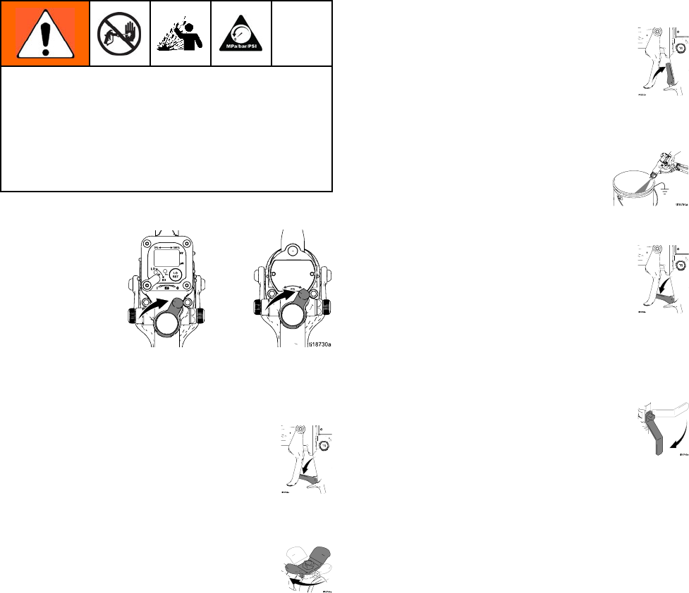
Follow the steps below to establish the correct
fluid flow and air flow. See Fig. 16 to locate the
electrostatic gun controls.
Figure 16 Electrostatic Gun Controls
1. Turn OFF (O) the ES On-Off switch (J).
2. Shut off the air bleed valve to the gun.
28 3A2497B
Operation
3. Check gun resistance. See
Test Gun Resistance, page 36.
4. Follow all steps under Grounding, page 21.
5. Follow all steps under
Check Gun Electrical Grounding, page 23.
Reading must be less than 100 ohms.
6. Connect the exhaust tube and secure with the
clamp provided.
7. Flush if needed. See Flushing, page 31.
To reduce the risk of a skin in-
jection injury, always follow the
Pressure Relief Procedure, page 26,
before removing or installing the spray tip, air
cap, or tip guard.
8. The fluid output and pattern width depend
on the size of the spray tip, the fluid
viscosity, and the fluid pressure. Use the
Spray Tip Selection Chart, page 71, as a guide
for selecting the appropriate spray tip for your
application.
9. Align the spray tip tab with the groove in the air
cap. Install the tip.
10. Install the air cap and retaining ring. Orientate
the air cap and tighten the retaining ring securely.
11. Close the atomizing air adjustment valve (G) and
the fan air adjustment valve (F).
12. Check that the ES On-Off switch is OFF (O).
13. Start the pump. Set the fluid regulator to 400 psi
(2.8 MPa, 28 bar).
14. Spray a test pattern. Examine the particle size in
the center of the pattern (tails will be removed
in step 18). Increase the pressure in small
increments. Spray another pattern. Compare
particle size. Continue increasing pressure until
the particle size remains constant. Do not exceed
3000 psi (21 MPa, 210 bar).
15. Turn ON (I) the ES On-Off switch.
3A2497B 29
Operation
16. Check that the ES indicator (Hz indicator on
Smart guns) is lit, or check that the kV indicator
on the isolated enclosure reads 30–50 kV.
The actual spraying voltage for AA waterborne
systems is 40–50 kV, but because the charging
electrode does not directly contact the fluid, the
voltage measured by the WB3000 kV meter will
be 5–10 kV lower. See the following table.
Table 2 . LED Indicator Colors
Indicator
Color
Description
Green When spraying, the indicator
should remain green, indicating
sufficient air pressure to the
alternator turbine.
Amber If the indicator turns amber after
1 second, the air pressure is too
low. Increase air pressure until
the indicator is green.
Red If the indicator turns red after 1
second, the air pressure is too
high. Decrease air pressure until
the indicator is green.
17. Set the gun air regulator to deliver a minimum of
45 psi (0.32 MPa, 3.2 bar) at gun when triggered,
to ensure full spraying voltage. See the table
below.
Table 3 . Pressure Drop
Air Hose
Length in ft (m)
(using 5/16 in. [8
mm] diameter hose)
Air Regulator Setting
in psi (MPa, bar)
[with gun triggered]
15 (4.6) 52 (0.36, 3.6)
25 (7.6) 57 (0.40, 4.0)
50 (15.3) 68 (0.47, 4.7)
75 (22.9) 80 (0.56, 5.6)
100 (30.5) 90 (0.63, 6.3)
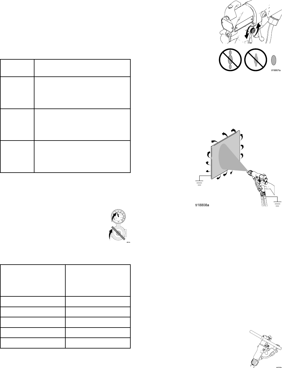
18. Turn the atomizing air adjustment valve
counterclockwise until any tails disappear.
19. If desired atomization is not achieved, change
the tip size. The smaller the tip orifice, the finer
the atomization.
20. Spray a test piece. Examine the edges
for coverage. If wrap is poor, see
Troubleshooting, page 40.
NOTE: If a narrower pattern is needed occasionally,
open the fan air adjustment valve slightly. (Excessive
fan air flow can cause paint buildup on the air cap.)
Shutdown
1. Discharge the system voltage. See Fluid Voltage
Discharge and Grounding Procedure, page 25.
2. Flush the gun. See Flushing, page 31.
3. Follow the Pressure Relief Procedure, page 26.
4. Hang the gun from its hook, with the nozzle
pointing down. Be sure to keep the gun from
grounding out.
30 3A2497B
Maintenance
Maintenance
Flushing
•Flushbefore
changing fluids, before fluid can dry
in the equipment, at the end of the day, before
storing, and before repairing equipment.
•Flushatthe
lowest pressure possible. Check
connectors for leaks and tighten as necessary.
•Flushwitha
non-flammable solvent that is
compatible with the fluid being dispensed and the
equipment wetted parts.
To reduce the risk of fire, explosion, or electric
shock, turn OFF (O) the ES On-Off switch before
flushing the gun.
Follow the Fluid Voltage Discharge and Grounding
Procedure, page 25, before flushing.
Only flush, purge, or clean the gun with fluids that
meet the following flammability requirements:
•FM, FMc Approved:
Material does not sustain burning in accordance
with the Standard Test Method for Sustained
Burning of Liquid Mixtures, ASTM D4206.
•CE-EN 50059 Compliant:
Materials which cannot be ignited, in any mixture
with air, by an energy source of less than 500mJ.
NOTICE
Only use non-flammable solvents when flushing
or cleaning equipment.
1. Turn OFF (O) the ES On-Off switch. Wait 30
seconds for the voltage to bleed off.
2. Discharge the system voltage. See Fluid Voltage
Discharge and Grounding Procedure, page 25.
3. Follow the Pressure Relief Procedure, page 26.
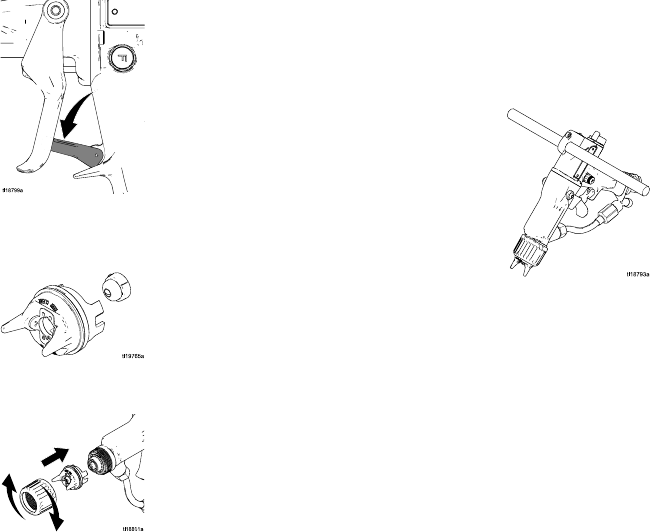
4. Removeandcleantheaircapandspraytip.
5. Change the fluid source to non-flammable
solvent.
6. Point the gun into a grounded metal pail. Flush
until clean solvent flows from the gun.
3A2497B 31
Maintenance
7. Follow the Pressure Relief Procedure, page 26.
Engage the trigger lock.
8. Align the spray tip tab with the groove in the air
cap. Install the tip.
9. Reinstall the air cap, tip guard, and retaining ring.
10. Open the isolated enclosure door. Leave the
flushing fluid in the system until you are ready
to spray again.
11. Hang the gun from its hook, with the nozzle
pointing down. Be sure to keep the gun from
grounding out.
12. Before using the system electrostatically again,
make sure no flammable vapors are present.
32 3A2497B
Maintenance
Clean the Gun Daily
1. Turn OFF (O) the ES On-Off switch.
2. Discharge the system voltage. See Fluid Voltage
Discharge and Grounding Procedure, page 25.
3. Follow the Pressure Relief Procedure, page 26.
4. Remove the air cap/tip guard and spray tip.
5. Flush the gun, see Flushing, page 31.
6. Follow the Pressure Relief Procedure, page 26.
7. Clean the outside of the gun with a non-flammable
solvent, as defined under Flushing, page 31.
Use a soft cloth. Point the gun down to prevent
solvent from entering the gun passages. Do not
immerse the gun.
3A2497B 33
Maintenance
8. Clean the air cap/tip guard and spray tip with a
soft brush and non-flammable solvent.
9. If necessary, use a toothpick or other soft tool to
clean the air cap holes. Do not use metal tools.
10. Align the spray tip tab with the groove in the air
cap. Install the tip.
11. Install the air cap and retaining ring. Orientate
the air cap and tighten the retaining ring securely.
34 3A2497B
Maintenance
Daily System Care
1. Follow the instructions under
Clean the Gun Daily, page 33. Follow
the Pressure Relief Procedure, page 26.
2. Clean the fluid and air filters.
3. Check for fluid leaks. Tighten all fittings.
4. Clean workpiece hangers. Use non-sparking
tools.
5. Check the movement of the trigger and valves.
Lubricate if necessary.
6. Check Gun Electrical Grounding, page 23.
7. Hang the gun from its hook, with the nozzle
pointing down.
8. Clean the cabinet:
• Inspect the cabinet and clean up any spilled
paint. Conductive paint residue allowed to
contact grounded parts may short out the
electrostatics.
•Keepthein
side of the cabinet clean, for proper
operation.
• Inspect the door T-handle locking screw
regularly, to ensure the threads are well
greased. Apply silicone-free grease to the
threads when necessary.
• Visually inspect the ground strip (240)
for damage. Replace if needed.
Measure theresistanceweekly. See
Test Ground Strip Resistance, page 39.
3A2497B 35
Electrical Tests
Electrical Tests
Use the following procedures to test the condition
of the power supply and gun body, and electrical
continuity between components.
NOTICE
The gun body resistor cartridge is part of the body
and is not replaceable. To avoid destroying the gun
body, do not attempt to remove the body resistor.
Use megohmmeter Part No. 241079 (AA) with an
applied voltage of 500 V. Connect the leads as
shown.
Megohmmeter Part No. 241079 (AA-see Fig.
17) is not approved for use in a hazardous area.
To reduce the risk of sparking, do not use the
megohmmeter to check electrical grounding
unless:
• The gun has been removed from the hazardous
area;
• Or all spraying devices in the hazardous area
are turned off, ventilation fans in the hazardous
area are operating, and there are no flammable
vapors in the area (such as open solvent
containers or fumes from spraying).
Failure to follow this warning could cause fire,
explosion, and electric shock and result in serious
injury and property damage.
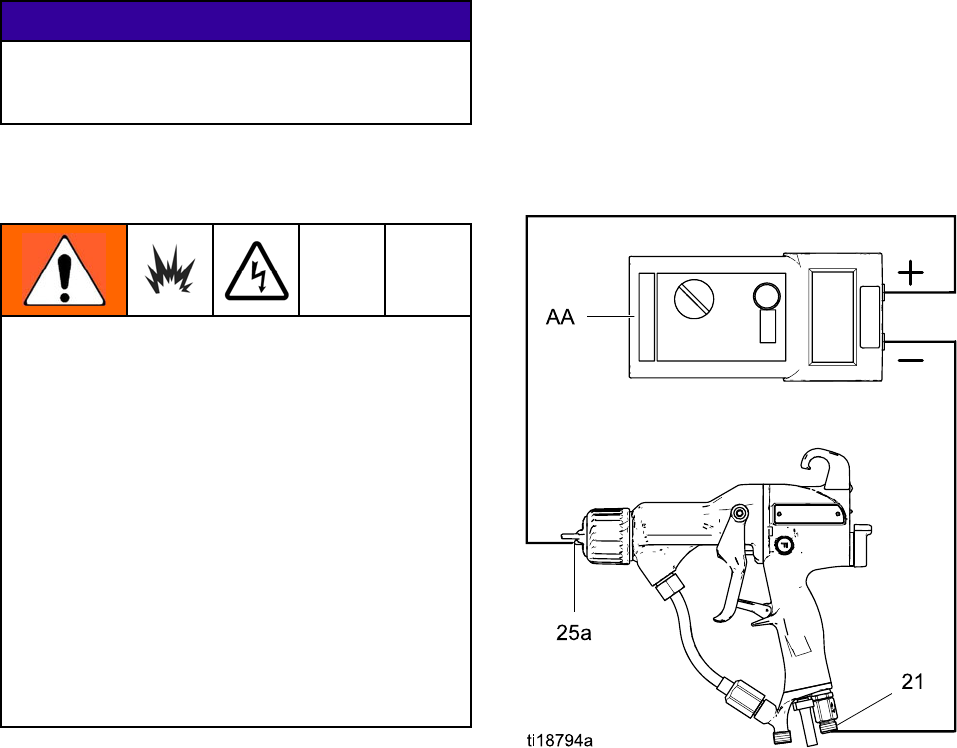
Test Gun Resistance
1. Flush and dry the fluid passage.
2. Measure resistance between the electrode
needle tip (25a) and the air swivel (21).
The resistance should be 104–150
megohms. If outside this range, go to
Test Power Supply Resistance, page 37.Ifin
range, see Electrical Troubleshooting, page 45 for
other possible causes of poor performance, or
contact your Graco distributor.
Figure 17 Test Gun Resistance
36 3A2497B
Electrical Tests
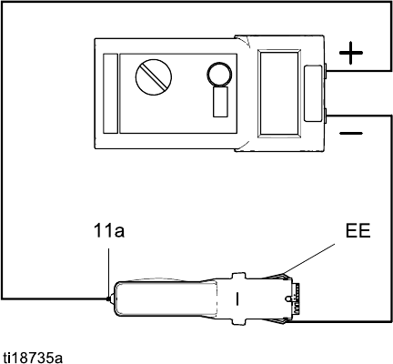
Test Power Supply Resistance
1. Remove the power supply (11). See Power
Supply Removal and Replacement, page 52.
2. Remove the alternator (15)
from the power supply. See
Alternator Removal and Replacement, page 53.
3. Measure resistance from the power supply's
ground strips (EE) to the spring (11a). The
resistance should be 90–115 megohms. If outside
this range, replace the power supply. If in range,
go to Test Gun Barrel Resistance, page 38.
4. Be sure the spring (11a) is in place before
reinstalling the power supply.
Figure 18 Test Power Supply Resistance
3A2497B 37
Electrical Tests
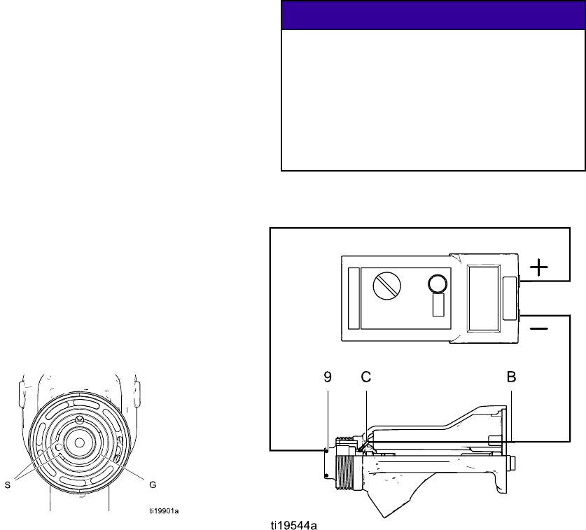
Test Gun Barrel Resistance
1. Insert a conductive rod (B) into the gun barrel
(which was removed for the power supply test)
and against the metal contact (C) in the front of
the barrel.
2. Measure the resistance between the conductive
rod (B) and the conductive ring (9). The
resistance should be 10–30 megohms. If the
resistance is incorrect, make sure the metal
contact (C) in the barrel and the conductive ring
(9) are clean and undamaged.
3. If the resistance is still outside the range,
remove the conductive ring (9) and measure the
resistance between the conductive rod (B) and
the wire lead at the bottom of the conductive ring
groove.
4. If the resistance is in range, replace the
conductive ring (9) with a new one. Insert the
ends of the conductive ring into the slots (S) at
the front of the barrel, then press the ring firmly
intothegroove(G).
NOTICE
The conductive ring (9) is a conductive metal
contact ring, not a sealing o-ring. For best
performance and to avoid potential damage to
the spray gun, do not remove the conductive
ring (9) except to replace it and never operate
the gun without the conductive ring in place.
Do not replace the conductive ring with
anything but a genuine Graco part.
5. If the resistance is still outside the range, replace
the gun barrel.
Figure 19 Test Gun Barrel Resistance
38 3A2497B
Electrical Tests
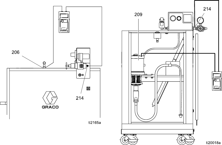
Test Ground Strip Resistance
Using an ohmmeter, measure the resistance between
the latch housing (206) and the ground lug (214).
The ground strip is grounded through the cart back
to the ground lug. Resistance must be less than 100
ohms. If greater than 100 ohms, replace the ground
strip (240).
Figure 20 Test Ground Strip Resistance
Test Cylinder Resistance
Remove the enclosure door. Using an ohmmeter,
measure the resistance from the pump (209) to the
ground lug (214). Resistance must be less than
100 ohms. If greater than 100 ohms, replace the
grounding cylinder.
Figure 21 Test Cylinder Resistance
3A2497B 39
Troubleshooting
Troubleshooting
Installing and servicing this equipment requires
access to parts which may cause an electric shock
or other serious injury if the work is not performed
properly. Do not install or service this equipment
unless you are trained and qualified.
Follow the Fluid Voltage Discharge and Grounding
Procedure, page 25 before checking or servicing
the system and whenever you are instructed to
discharge the voltage.
To reduce the risk of a skin injection injury, always
follow the Pressure Relief Procedure, page 26,
whenever you are instructed to relieve the
pressure.
NOTE: Check all possible remedies in the
Troubleshooting Chart before disassembling the gun.
Voltage Loss Troubleshooting
Normal spraying voltage for a system using the
waterborne gun is 40–50 kV. The system voltage is
lower due to spraying current demands and voltage
isolation system losses.
A loss of spraying voltage can be caused by a
problem with the spray gun, fluid hose, or voltage
isolation system, since all of the system components
are electrically connected through the conductive,
waterborne fluid.
Before troubleshooting or servicing the voltage
isolation system itself, you need to determine which
component in the system is most likely causing a
problem. Possible causes include the following:
Spray Gun
• Fluid leakage
• Dielectric breakdown at the fluid hose connection
or fluid packings
• Not enough air pressure for the alternator turbine
• Faulty power supply
• Excessive overspray on gun surfaces
• Fluid in the air passages
Waterborne Fluid Hose
• Dielectric failure of the hose (pin-hole leak in the
inner layer)
• Air gap in the fluid column between the gun and the
isolated fluid supply, causing a low voltage reading
on the isolation system voltage meter.
Voltage Isolation System
• Fluid leakage
• Dirty interior
40 3A2497B
Troubleshooting
Visual Checks
First, check the system for any visible faults or errors
to help isolate whether the spray gun, fluid hose or
voltage isolation system has failed. A voltage probe
and meter, part no. 245277, is helpful for diagnosing
voltage problems and is required for some of the
troubleshooting tests that follow.
1. Check that all of the air and fluid tubes and hoses
are properly connected.
2. Check that the voltage isolation system valves
and controls are properly set for operation.
3. Check that the interior of the isolated enclosure
is clean.
4. Check that the spray gun and voltage isolation
system have sufficient air pressure.
5. Check that the gun ES ON/OFF valve is in the
ON position and that the gun ES indicator light
is on. If the ES indicator light is not on, remove
the spray gunforserviceandcompletethe
Electrical Tests, page 36.
6. Check that the voltage isolation system's
enclosure door is closed and that any safety
interlocks are engaged and working properly.
7. Make sure the voltage isolation system is in
the “isolate” mode, where it is isolating the fluid
voltage from ground.
8. To eliminate air gaps in the fluid column, spray
enough fluid to purge the air out between the
voltage isolation system and the spray gun. An
air gap in the fluid hose can break the electrical
continuity between the spray gun and the isolated
fluid supply and cause a low voltage reading on
a voltage meter connected to the isolated fluid
supply.
9. Check the spray gun cover and barrel for
accumulated overspray. Excessive overspray
can create a conductive path back to the
grounded gun handle. Install a new gun cover
and clean the exterior of the gun.
10. Inspect the entire system for any visible fluid
leakage and repair any fluid leaks that are found.
Pay special attention to the following areas:
•Packinga
rea of the spray gun.
• Fluid hose: check for leakage or any bulges in
the outer cover, which may indicate an internal
leak.
• Internal voltage isolation system components
3A2497B 41
Troubleshooting
Tests
If you still have no voltage, separate the spray gun
and hose from the voltage isolation system and
check whether the gun and hose alone will hold
voltage with the following test.
1. Flush the system with water and leave the lines
filled with water.
2. Discharge the system voltage (see Fluid Voltage
Discharge and Grounding Procedure, page 25).
3. Follow the Pressure Relief Procedure, page 26.
4. Disconnect the fluid hose from the voltage
isolation system.
Avoid allowing any water to leak out of the fluid
hose as that could cause a significant air gap in
the fluid column up to the gun electrode, which
can break the conductivity path and conceal a
potential failure area.
5. Position the end of the hose as far as possible
away from any grounded surface. The end of
the hose must be at least 1 ft. (0.3 m) from any
ground. Make sure that no one is within 3 ft. (0.9
m) of the end of the hose.
6. Turn the ES ON/OFF valve to ON and trigger
the gun just enough to turn on the air to the gun
but not the fluid. Measure the voltage at the gun
electrode with a voltage probe and meter.
7. Discharge the system voltage by waiting 30
seconds and then touching the gun electrode
with a grounded rod.
8. Check the meter reading:
• If the meter reading is 40 to 50 kV, the gun and
fluid hose are okay, and the problem is in the
voltage isolation system.
• If the meter reading is below 40 kV, the
problem is in the gun or fluid hose.
9. Flush the fluid hose and gun with enough air to
dry out the fluid passages.
10. Turn the ES ON/OFF valve to ON and trigger the
gun. Measure the voltage at the gun electrode
with a voltage probe and meter.
• If the meter reading is 40-50 kV, the gun
power supply is okay, and there is probably a
dielectric breakdown somewhere in the fluid
hose or gun. Continue with step 11.
• If the meter reading is below 40 kV, do
the Electrical Tests, page 36,tocheckthegun
and power supply resistance. If those tests
show the gun and power supply are okay,
continue with step 11.
11. A dielectric breakdown is most likely in one of
the following three areas. Repair or replace the
component that is failing.
a. Fluid hose:
• Check for leakage or any bulges in the
outer cover, which may indicate a pin-hole
leak through the inner layer. Disconnect
the fluid hose from the gun, and look for
signs of fluid contamination on the outside
of the inner portion of the fluid tube.
• Inspect the end of the hose connected to
the voltage isolation system. Look for cuts
or nicks.
b. Fluid needle:
Remove the fluid needle from the gun
(see Fluid Needle Replacement, page 51),
and look for signs of fluid leakage or any
blackened areas, which would indicate arcing
is occurring along the packing rod.
c. Fluid hose connection to the spray gun:
Abrea
kdown at the fluid hose connection
joint would be caused by fluid leaking past
the hose fittings. Remove the hose at the
gun connection and look for signs of fluid
leakage.
12. Before reassembling the gun, clean and dry the
gun fluid inlet tube. Repack the inner spacer of
the fluid packing rod with dielectric grease and
reassemble the gun.
13. Reconnect the fluid hose.
14. Check the gun voltage with the voltage probe
and meter before filling the gun with fluid.
423A2497B
Troubleshooting
Spray Pattern Troubleshooting
NOTE: Some spray pattern problems are caused by the improper balance between air and fluid.
Problem Cause Solution
No fluid. Refill supply.
Fluttering or spitting spray.
Air in fluid supply. Check fluid source. Refill.
Fluid buildup; partially plugged tip. Clean. See
Clean the Gun Daily, page 33.
Irregular pattern.
Worn/damaged tip or air cap holes. Clean or replace.
Pattern pushed to one side; air
cap gets dirty.
Air cap holes plugged. Clean. See
Clean the Gun Daily, page 33.
Air pressure too low. Open atomizing air adjustment
valve.
Tails in pattern.
Fluid pressure too low. Increase.
Air pressure too high. Decrease.
Fluid pressure too low. Increase.
Fluid buildup on air cap/tip guard.
Air cap holes plugged. Clean. See
Clean the Gun Daily, page 33.
3A2497B 43

Troubleshooting
Gun Operation Troubleshooting
Problem Cause Solution
Atomizing air pressure too high. Close atomizing air valve part way,
or decrease air pressure as low
as possible; minimum 45 psi (0.32
MPa, 3.2 bar) needed at gun for
full voltage.
Excessive spray fog.
Fluid too thin. Increase viscosity.
Atomizing air pressure too low. Open atomizing air valve more or
increase gun air inlet pressure;
use lowest air pressure necessary.
Spray tip is too large. Use smaller tip. See Spray Tip
Selection Chart, page 71.
Poorly mixed or filtered fluid. Remix or refilter fluid.
“Orange Peel” finish.
Fluid too thick. Reduce viscosity.
Fluid leaks from the fluid packing
area.
Worn fluid needle packings or rod. See Fluid Needle Replacement,
page 51.
Air leaks from the front of the gun. Air valve is not seating properly. See Air Valve Repair, page 57.
Worn or damaged fluid needle ball. See Fluid Needle Replacement,
page 51.
Worn fluid seat housing. See Air Cap, Spray Tip, and Fluid
Seat Housing Replacement, page
48.
Loose spray tip. Tighten retaining ring.
Fluid leakage from the front of the
gun.
Damaged tip seal. See Air Cap, Spray Tip, and Fluid
Seat Housing Replacement, page
48.
Low fluid supply. Add fluid if necessary.
Damaged spray tip. Replace.
Dirty or clogged spray tip. Clean. See
Clean the Gun Daily, page 33.
Gun does not spray.
Damaged fluid needle. See Fluid Needle Replacement,
page 51.
Dirty air cap. Damaged or plugged air cap. Clean air cap. See
Clean the Gun Daily, page 33.
Poor grounding. See Grounding, page 21.
Excessive paint wrap back to
operator. Incorrect distance from gun to part. Should be 8–12 in. (200–300 mm).
443A2497B

Troubleshooting
Electrical Troubleshooting
Problem Cause Solution
ES On/Off switch is OFF (O). Turn ON (I).
Gun air pressure too low (ES
indicator is amber).
Check air pressure to gun;
minimum45psi(0.32MPa,3.2
bar) needed at gun for full voltage.
Atomizing air pressure too high. Decrease.
Fluid pressure too high. Decrease, or replace worn tip.
Incorrect distance from gun to part. Should be 8-12 in. (200-300 mm).
Poorly grounded parts. Resistance must be 100 ohms or
less. Clean workpiece hangers.
Faulty gun resistance. See
Test Gun Resistance, page 36.
Fluid leaks from the fluid needle
packings and causes a short.
See Fluid Needle Replacement,
page 51.
Poor wrap.
Faulty alternator. See Alternator Removal and
Replacement, page 53.
ES On/Off switch is OFF (O). Turn ON (I).ES or Hz indicator is not lit.
No power. Check power supply, alternator,
and alternator ribbon cable. See
Power Supply Removal and
Replacement, page 52 and
Alternator Removal and
Replacement, page 53.
Operator not grounded or is near
ungrounded object.
See Grounding, page 21.
Operator gets mild shock.
Gun not grounded. See Check Gun Electrical
Grounding, page 23,and
Test Gun Resistance, page 36.
Operator gets shock from
workpiece.
Workpiece not grounded. Resistance must be 100 ohms or
less. Clean workpiece hangers.
3A2497B 45

Troubleshooting
Problem Cause Solution
Gun is too close to the part being
sprayed.
Gun should be 8–12 in. (200–300
mm) from the part.
Voltage/current display stays red
(smart guns only).
Dirty gun. See Clean the Gun Daily, page 33.
ES or Hz indicator is amber. Air turbine speed is too low. Increase air pressure until
indicator is green. To avoid
over-atomization, use the
atomizing air restrictor valve to
reduce the atomizing air to the air
cap.
ES or Hz indicator is red. Air turbine speed is too high. Decrease air pressure until
indicator is green.
Error display appears and Hz
indicator is red (Smart guns only).
Smart module has lost
communication with the power
supply.
Check for good connections
between Smart Module and
power supply. See Smart Module
Replacement, page 58,and
Power Supply Removal and
Replacement, page 52.
46 3A2497B
Repair
Repair
Prepare the Gun for Service
Installing and repairing this equipment requires
access to parts that may cause electric shock or
other serious injury if the work is not performed
properly. Do not install or service this equipment
unless you are trained and qualified.
To reduce the risk of injury, follow the
Pressure Relief Procedure, page 26, before
checking or servicing any part of the system
and whenever you are instructed to relieve the
pressure.
• Check all possible remedies in
Troubleshooting, page 40, before disassembling
the gun.
• Use a vise with padded jaws to prevent damage
to plastic parts.
• Lubricate the some needle assembly parts (20)
and certain fluid fittings with dielectric grease (57),
as specified in the text.
• Lightly lubricate o-rings and seals with non-silicone
grease. Order Part No. 111265 Lubricant. Do not
over-lubricate.
• Only use genuine Graco parts. Do not mix or use
parts from other PRO Gun models.
• Air Seal Repair Kit 24N789 is available. The
kit must be purchased separately. Kit parts are
marked with an asterisk, for example (3*).
1. Flush the gun. See Flushing, page 31.
2. Relieve the pressure. See
Pressure Relief Procedure, page 26.
3. Disconnect the gun air and fluid lines.
4. Remove the gun from the worksite. Repair area
must be clean.
3A2497B 47
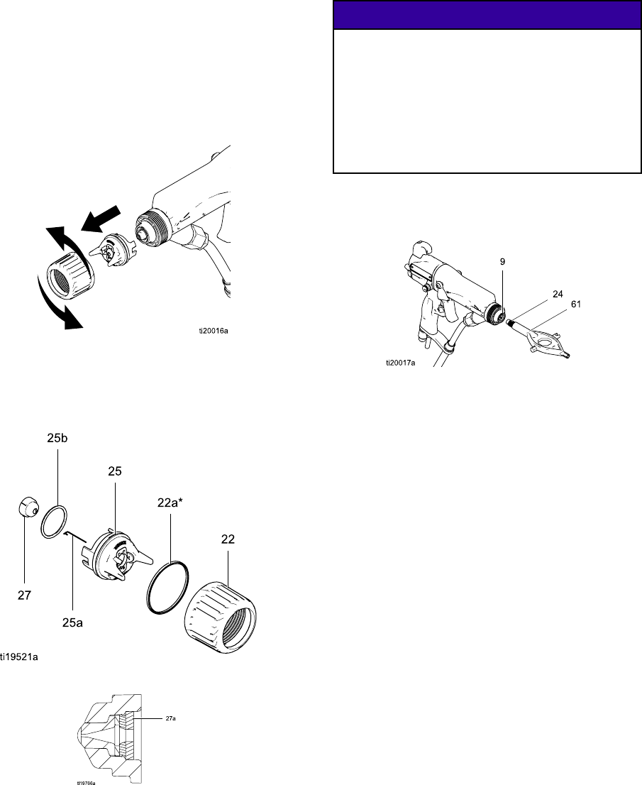
Repair
Air Cap, Spray Tip, and Fluid Seat
Housing Replacement
1. See Prepare the Gun for Service, page 47.
2. Remove the retainer ring (22) and air cap/tip
guard assembly (25).
Figure 22 Remove Air Cap
3. Disassemble the air cap assembly. Check the
condition of the u-cup (22a), o-ring (25b), and tip
gasket (27a). Replace any damaged parts.
Figure 23 Disassemble Air Cap Assembly
Figure 24 Tip Gasket
4. To replace the electrode (25a), see
Electrode Replacement, page 49.
NOTICE
The conductive ring (9) is a conductive metal
contact ring, not a sealing o-ring. For best
performance and to avoid potential damage to
the spray gun, do not remove the conductive
ring (9) except to replace it and never operate
the gun without the conductive ring in place.
Do not replace the conductive ring with
anything but a genuine Graco part.
5. Trigger the gun and remove the fluid seat housing
(24), using the multi-tool (61).
Figure 25 Replace Fluid Seat Housing
48 3A2497B
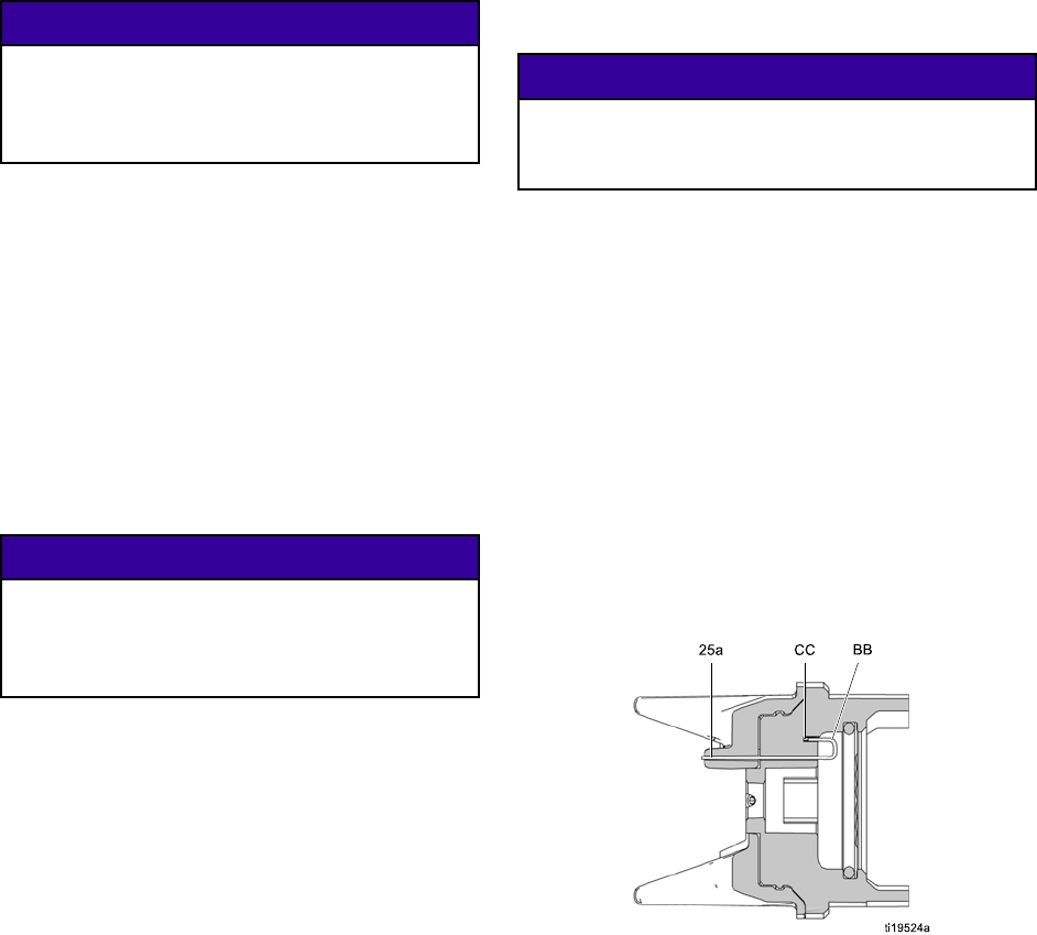
Repair
NOTICE
Do not overtighten the fluid seat housing (24).
Overtightening may damage the housing and
the gun barrel, resulting in improper fluid
shutoff.
6. Trigger the gun and install the fluid seat housing
(24). Tighten until snug, then 1/4 turn more.
7. Check that the spray tip gasket (27a) is in place.
Align the spray tip tab with the groove in the air
cap (25). Install the spray tip (27) in the air cap.
8. Make sure that the electrode (25a) is installed
correctly in the air cap.
9. Check that the air cap o-ring (25b) is in place.
10. Check that the u-cup (22a) is in place on the
retainingring(22). Thelipsoftheu-cupmust
face forward.
NOTICE
To avoid damaging the tip guard, orient the
air cap assembly (25) before tightening the
retaining ring (22). Do not turn the air cap
when the retaining ring is tight.
11. Orientate the air cap and tighten the retaining
ring securely.
12. See Test Gun Resistance, page 36.
Electrode Replacement
NOTICE
For best performance and to avoid potential
damage to the spray gun, do not operate the spray
gun without the electrode installed in the air cap.
1. See Prepare the Gun for Service, page 47.
2. Remove the air cap assembly (25). See
Air Cap, Spray Tip, and Fluid Seat Housing
Replacement, page 48.
3. Pull the electrode (25a) out of the back of the air
cap, using a needle-nose pliers.
4. Push the new electrode through the air cap hole.
Make sure the short end (BB) of the electrode
engages thehole(CC)inthebackoftheair
cap. Press the electrode in place firmly with your
fingers.
5. Install the air cap assembly.
6. See Test Gun Resistance, page 36.
Figure 26 Replace Electrode
3A2497B 49
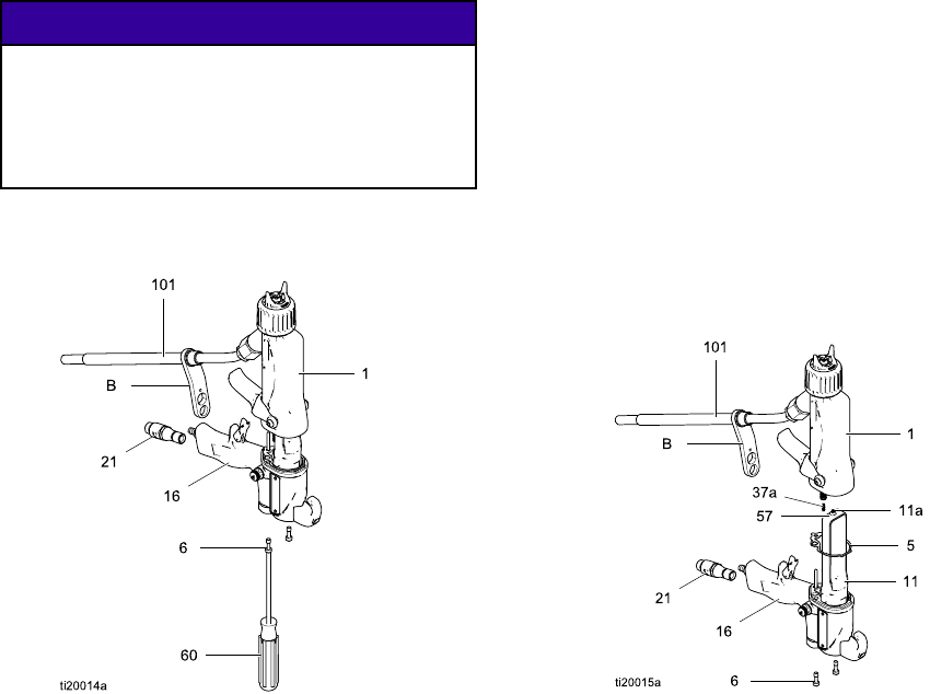
Repair
Gun Barrel Removal
1. See Prepare the Gun for Service, page 47.
2. Remove the air inlet fitting (21) and take the
bracket (B) off the gun handle (16).
3. Loosen the two screws (6).
NOTICE
To avoid damaging the power supply (11),
pull the gun barrel straight away from the gun
handle. If necessary, gently move the gun
barrel from side to side to free it from the gun
handle.
4. Hold the gun handle (16) with one hand and pull
the barrel (1) straight off the handle.
Figure27 GunBarrelRemoval
Gun Barrel Installation
1. Be sure the gasket (5*) and grounding spring
(37a) are in place. Make sure the gasket air
holes are aligned properly. Replace the gasket if
damaged.
2. Make sure the spring (11a) is in place on the
tip of the power supply (11). Liberally apply
dielectric grease (57) to the tip of the power
supply. Place the gun barrel (1) over the power
supply and onto the gun handle (16).
3. Tighten the two screws (6) oppositely and evenly
(about a half turn past snug). Do not over-tighten
the screws (6).
4. Position the bracket (B) on the gun handle (16)
and secure with the air inlet fitting (21).
5. See Test Gun Resistance, page 36.
Figure 28 Gun Barrel Installation
50 3A2497B
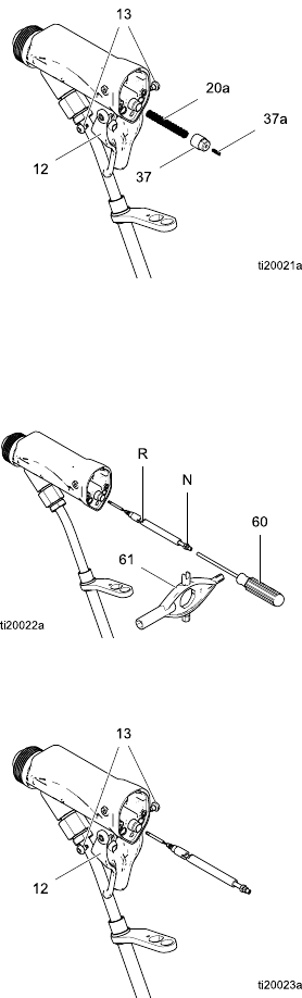
Repair
Fluid Needle Replacement
1. See Prepare the Gun for Service, page 47.
2. Remove the air cap assembly and fluid seat
housing. See Air Cap, Spray Tip, and Fluid Seat
Housing Replacement, page 48.
3. Remove the gunbarrel. See
Gun Barrel Removal, page 50.
4. Remove the trigger screws (13) and trigger (12).
5. Unscrew the spring cap (37). Remove the spring
(20a).
6. Insert the supplied driver (60) in the socket at the
back of the fluid needle. Press forward so the two
segments of the needle engage (R). This allows
the needle to be unscrewed from the gun body.
7. Using the multi-tool (61), pull back on the packing
nut (N) to remove the fluid needle assembly.
8. Install the fluid needle assembly in the gun barrel.
Push in on the needle with the driver (60) and
tighten.
9. Install the spring (20a).
10. Install the spring cap (37). Make sure the
grounding spring (37a) is in place.
11. Install the trigger (12) and screws (13).
12. Install the gun barrel. See
Gun Barrel Installation, page 50.
13. Install the seat housing and air cap assembly.
See Air Cap, Spray Tip, and Fluid Seat Housing
Replacement, page 48.
14. See Test Gun Resistance, page 36.
Figure 29 Remove Cap and Springs
Figure 30 Remove Fluid Needle
Figure 31 Replace Fluid Needle
3A2497B 51
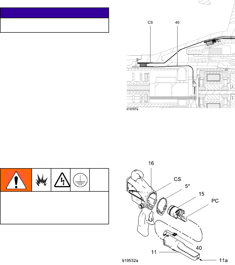
Repair
Power Supply Removal and Replacement
• Inspect the gun handle power supply cavity for dirt
or moisture. Clean with a clean, dry rag.
• Do not expose gasket (5) to solvents.
1. See Prepare the Gun for Service, page 47.
2. See Gun Barrel Removal, page 50.
NOTICE
Be careful when handling the power supply
(11) to avoid damaging it.
3. Grasp the power supply (11) with your hand.
Withagentlesidetosidemotion,freethepower
supply/alternator assembly from the gun handle
(16), then carefully pull it straight out.
On Smart
Models only,
disconnect the flexible circuit (40)
from the socket at the top of the handle.
4. Inspect the power supply and alternator for
damage.
5. To separate the power supply (11) from the
alternator (15), disconnect the 3-wire ribbon
connector (PC) from the power supply.
On Smart
Models only,
disconnect the 6–pin flexible circuit
(40) from the power supply. Slide the alternator
up and off the power supply.
6. See Test Power Supply Resistance, page 37.
Replace the power supply if necessary.
To repair the alternator, see
Alternator Removal and Replacement, page 53.
7.
Smart models only:
connect the 6–pin flexible
circuit (40) to the power supply.
To prevent damage to the cable and possible
interruption of the ground continuity, bend the
alternator’s 3–wire ribbon cable (PC) upward
and back, so the bend faces the power supply
and the connector is at the top.
8. Connect the 3-wire ribbon connector (PC) to the
power supply. Tuck the ribbon forward, under
the power supply. Slide the alternator (15) down
onto the power supply (11).
9. Insert the power supply/alternator assembly in
the gun handle (16). Make sure the ground strips
make contact with the handle. On Smart models,
align the connector of the 6–pin flexible circuit
(40) with the socket (CS) at the top of the handle.
Push the connector securely into the socket as
you slide the power supply/alternator assembly
into the handle.
Figure 32 Connect Flexible Circuit
10. Make sure the gasket (5*), ground spring (37a),
and power supply spring (11a) are in place.
Assemble the barrel (1) to the handle (16). See
Gun Barrel Installation, page 50.
11. See Test Gun Resistance, page 36.
Figure 33 Power Supply
52 3A2497B
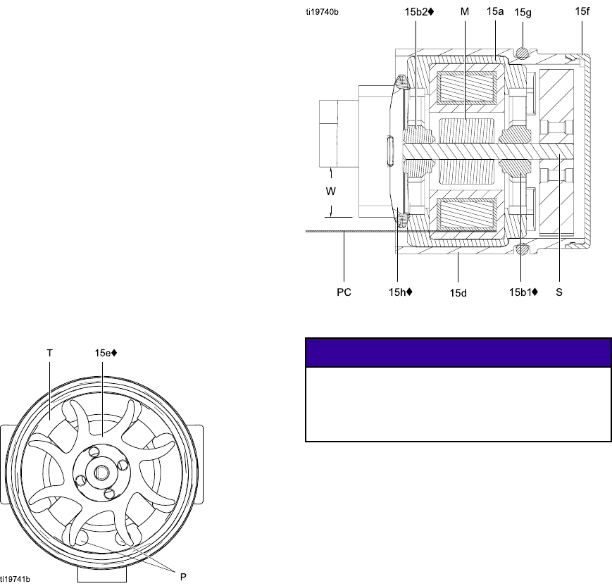
Repair
Alternator Removal and Replacement
NOTE: Replace alternator bearings after 2000 hours
of operation. Order Part No. 24N706 Bearing Kit.
Parts included in the kit are marked with a symbol (♦).
1. See Prepare the Gun for Service, page 47.
2. Remove the power supply/alternator assembly
and disconnect the alternator. See Power Supply
Removal and Replacement, page 52.
3. Measure resistance between the two outer
terminals of the 3-wire connector (PC); it should
be 2.0–6.0 ohms. If outside this range, replace
the alternator coil (15a).
4. Using a flat blade screwdriver, pry the clip (15h)
off the housing (15d). Remove the cap (15f),
using a thin blade or screwdriver.
5. If necessary, rotate the fan (15e) so its blades
clear the four bearing tabs (T) of the housing
(15d).
Figure 34 Fan Orientation
6. Push the fan and coil assembly (15a) out the
front of the housing (15d).
Figure 35 Alternator Cross-Section
NOTICE
Do not scratch or damage the magnet (M) or
shaft (S). Do not pinch or damage the 3–wire
connector (PC) when disassembling and
reassembling the bearings.
7. Hold the coil assembly (15a) on a workbench
with thefanendfacingup. Usingawideblade
screwdriver, pry the fan (15e) off the shaft (S).
8. Remove the top bearing (15b2).
9. Remove the bottom bearing (15b1).
10. Install the new bottom bearing (15b1♦) on the
long end of the shaft (S). The flatter side of the
bearing must face away from the magnet (M).
Install in the coil (15a) so the bearing blades are
flush with the surface of the coil.
11. Press the new top bearing (15b2♦) onto the short
end of the shaft so the bearing blades are flush
with the surface of the coil (15a). The flatter side
of the bearing must face away from the coil.
3A2497B 53
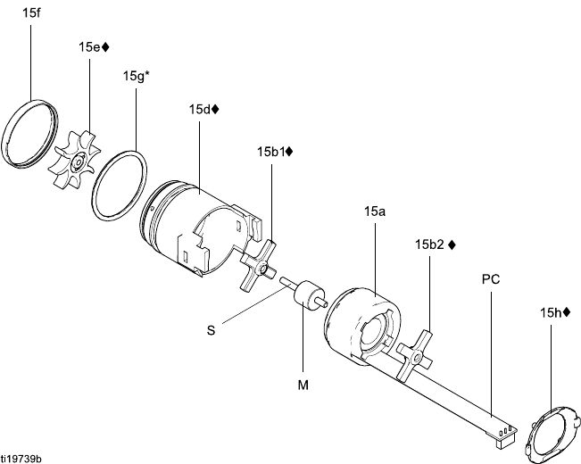
Repair
12. Hold the coil assembly (15a) on a workbench
with the fan end facing up. Press the fan (15e♦)
onto the long end of the shaft (S). The fan blades
must be oriented as shown.
13. Carefully press the coil assembly (15a) into
the front of the housing (15d♦). The 3–wire
connector (PC) must be positioned below the
wider notch (W) of the housing tabs, as shown in
Fig. 35. Be sure the coil alignment pins (P) are
positioned as shown in Fig. 34.
14. Rotate the fan (15e) so its blades clear the four
bearing tabs (T) at the back of the housing.
Ensure that the blades of the bottom bearing
(15b1♦) align with the tabs.
15. Seat the coil fully into the housing (15d♦). Secure
with the clip (15h♦), ensuring that its tabs engage
the slots in the housing.
16. Ensurethattheo-ring(15g)isinplace. Install
the cap (15f).
17. Install the alternator on the power supply, and
install both parts in the handle. See Power
Supply Removal and Replacement, page 52.
Figure 36 Alternator
54 3A2497B
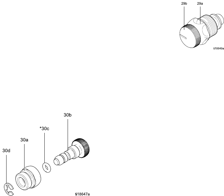
Repair
Fan Air Adjustment Valve Repair
1. See Prepare the Gun for Service, page 47.
2. Place a wrench on the flats of the valve assembly
(30) and unscrew it from the handle (16).
NOTE: You may replace the valve as an
assembly (go to step 9) or as individual parts
(steps 3-9).
3. Remove the retaining ring (30d).
4. Turn the valve shaft (30b) counterclockwise until
it comes free from the valve housing (30a).
5. Remove the o-ring (30c).
6. Clean all parts and inspect for wear or damage.
NOTE: Use non-silicone grease, Part No.
111265. Do not over-lubricate.
7. When reassembling the fan air valve (30), lightly
lubricate the valve threads and screw the shaft
(30b) fully into the housing (30a) until bottomed.
Install the o-ring (30c*), lubricate, and unscrew
the valve stem until the o-ring enters the housing.
8. Reassemble the retaining ring (30d). Unscrew
the valve stem from the housing until it is stopped
by the retaining ring.
9. Screw the valve assembly (30) into the gun
handle (16),usingawrenchontheflatsofthe
housing. Torque to 15 in-lb (1.7 N•m).
Figure 37 Fan Air Adjustment Valve
Atomizing Air Adjustment Valve
Repair
1. See Prepare the Gun for Service, page 47.
2. Place a wrench on the flats of the valve assembly
(29) and unscrew it from the handle (16).
3. Inspect the valve assembly. If damaged, install
a new valve (29).
4. Before installing the valve assembly in the
handle, unscrew the valve stem (29b) from the
housing (29a) until it stops.
5. Install the valve assembly into the gun handle.
Torque the valve housing (29a) to 15 in-lb (1.7
N•m).
Figure 38 Atomizing Air Adjustment Valve
3A2497B 55
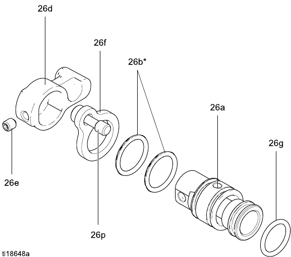
Repair
ES On-Off Valve Repair
1. See Prepare the Gun for Service, page 47.
2. Loosen the captive screw (26p). Remove the
valve (26) from the handle.
3. Lubricate the o-rings (26b* and 26g*) with
non-silicone grease, Part No. 111265. Do not
over-lubricate.
NOTE: Do not over-lubricate parts. Excessive
lubricant ontheo-ringscanbepushedintothe
gun air passage and blemish the finish on the
workpiece.
4. Clean and inspect parts for damage. Replace
if necessary.
NOTE: The protrusion on the retainer plate (26f)
must point upward.
5. Reinstall the valve. Torque the screw (26p) to
15-25 in-lb (1.7-2.8 N•m).
Figure 39 ES On-Off Valve
56 3A2497B
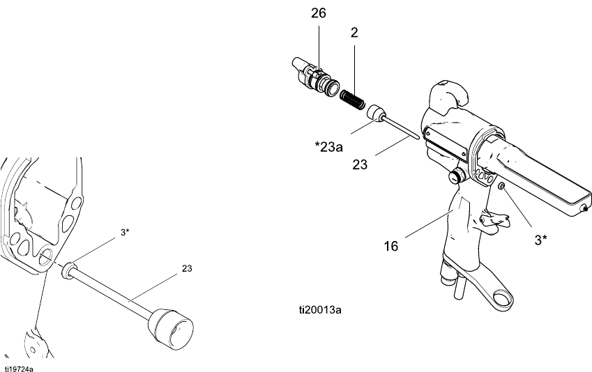
Repair
Air Valve Repair
1. See Prepare the Gun for Service, page 47.
2. See Gun Barrel Removal, page 50.
3. Remove the screws (13) and trigger (12).
4. Remove the ES On-Off Valve. See
ES On-Off Valve Repair, page 56.
5. Remove the spring (2).
6. Push on the front of the air valve shaft to force it
out the back of the handle. Inspect the rubber
seal (23a*) and replace if damaged.
7. Inspect the u-cup (3). Do not remove the u-cup
unless damaged. If removed, install the new one
with its lips facing into the gun handle (16). Place
the u-cup on the shaft of the air valve to help seat
it in the gun handle.
Figure 40 Install U-Cup
8. Install the air valve (23) and spring (2) into the
gun handle (16).
9. Install the ES On-Off Valve. See
ES On-Off Valve Repair, page 56.
10. Install the trigger (12) and screws (13).
11. See Gun Barrel Installation, page 50.
Figure 41 Air Valve
3A2497B 57
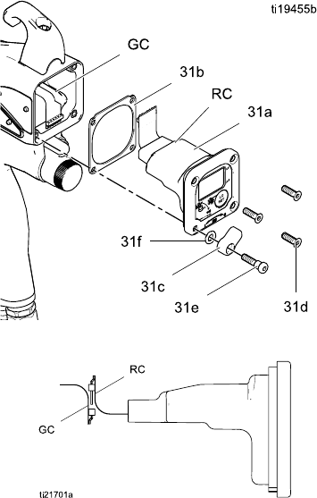
Repair
Smart Module Replacement
If the Error display appears, the Smart Module has
lost communication with the power supply. Check for
good connections between the Smart Module and
the power supply.
If the module’s LEDs are not lighting, replace the
module.
1. See Prepare the Gun for Service, page 47.
2. Remove the pivot screw (31e), o-ring (31f), and
ES HI/LO switch (31c) at the bottom left corner of
the Smart Module cartridge (31a).
3. Remove the remaining three screws (31d) from
the cartridge.
4. Pull the Smart Module out the back of the gun.
Disconnect the ribbon cable (RC) from the
connector (GC) in the gun handle.
5. Remove the gasket (31b).
6. Install a new gasket (31b) on the new cartridge
(31a). Make sure the notched corners of the
gasket are at the top.
7. Align the module’s ribbon cable (RC) with
the gun’s cable (GC) and slide them securely
together, as shown. Tuck the connected cables
into the recess of the gun handle. Install the
module flush to the back of the gun handle.
8. Install the pivot screw (31e), o-ring (31f), and
ES HI/LO switch in the bottom left corner of the
cartridge (31a).
9. Install the three remaining screws (31d). Torque
to 7–9 in-lb (0.8–1.0 N•m).
Figure 42 Smart Module
Figure 43 Align Ribbon Cables
58 3A2497B
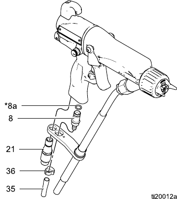
Repair
Air Swivel and Exhaust Valve Replacement
1. See Prepare the Gun for Service, page 47.
2. To replace the air exhaust valve:
a. Remove the clamp (36) and the exhaust tube
(35).
b. Unscrew the swivel (21) from the gun handle
(16). The swivel is a left-hand thread. Move
thebracketoutoftheway.
c. Pull the exhaust valve (8) from the handle
(16). Inspect the o-ring (8a) and replace if
necessary.
d. Install the o-ring (8a*) on the exhaust valve
(8). Lubricate the o-ring with a light coating
of non-silicone grease.
e. Install the exhaust valve (8) in the handle
(16).
f. Apply thread sealant to the top threads of the
swivel (21). Position the bracket and screw
the swivel into the gun handle (16). Torque
to 75–85 in-lb (8.4–9.6 N•m).
g. Install the tube (36) and clamp (43).
3. To replace the air inlet swivel:
a. Unscrew the swivel (21) from the gun handle
(16). The swivel is a left-hand thread.
b. Apply thread sealant to the top threads of the
swivel. Screw the swivel into the gun handle.
Torque to 75–85 in-lb (8.4–9.6 N•m).
Figure 44 Air Inlet Fitting and Air Exhaust Valve
3A2497B 59
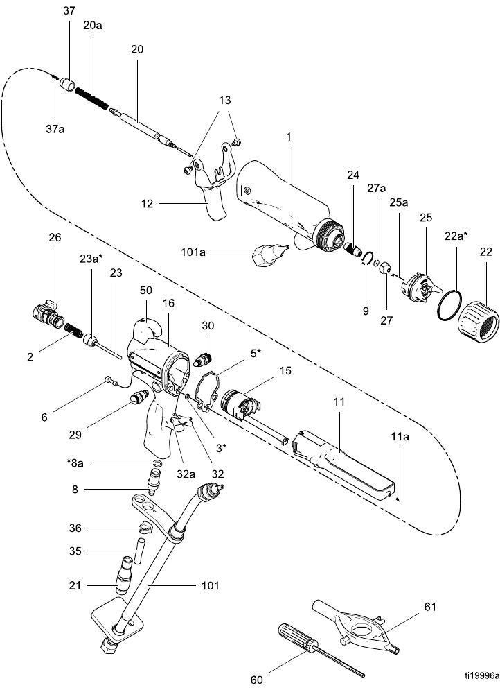
Parts
Parts
Standard Air-Assisted Spray Gun Assembly
Part No. H60T18 60 kV Electrostatic Air-Assisted Spray Gun, Series A, includes items 1–61
Part No. 24M508 Unshielded Waterborne Fluid Hose (101), sold separately
60 3A2497B

Parts
Part No. H60T18 60 kV Electrostatic Air-Assisted Spray Gun, Series A, includes items 1–61
Part No. 24M508 Unshielded Waterborne Fluid Hose (101), sold separately
Ref.
No.
Part No. Description Qty
124N745 BODY, gun 1
2 185116 SPRING, compression 1
3* 188749 PACKING, u-cup 1
5* 24N699 GASKET, body 1
624N740
SCREW, hex socket;
package of 2
1
724N742 BRACKET 1
8 249323 VALVE, exhaust 1
8a* 112085 O-RING 1
924N747
RING, conductive 1
11 24N662 POWER SUPPLY, 60 kV gun 1
11a 24N979 SPRING 1
12 24N663 TRIGGER; includes item 13 1
13 24A445 SCREW, trigger; package of 2 1
15 24N664 See
Alternator Assembly, page 67
1
16 24P746 HANDLE; 60 kV AA gun 1
20 24N781 NEEDLE ASSEMBLY; includes
item 20a
1
20a 24N782 SPRING, fluid needle 1
21 24N626 SWIVEL, air inlet; M12 x 1/4
npsm(m); left-hand thread
1
22 24N793 RING, retainer; includes 22a 1
22a* 198307 PACKING, u-cup; UHMWPE;
part of 22
1
23 24N633 VALVE, air 1
23a* 276733 SEAL 1
24 24N725 HOUSING, seat 1
25 24N727 See Air Cap Assembly, page 70 1
25a 24N643 ELECTRODE; package of 5 1
26 24N632 See ES On-Off Valve Assembly,
page68
1
Ref.
No.
Part No. Description Qty
27 AEMxxx
AEFxxx
TIP ASSEMBLY; customer’s
choice; includes item 27a
1
27a 183459 GASKET, tip 1
29 24N792 ATOMIZING AIR
ADJUSTMENT VALVE
1
30 24N634 See Fan Air Valve Assembly,
page 69
1
32 24E404 STOP, trigger; includes item 32a 1
32a ——— PIN, dowel 1
35 185103 TUBE, exhaust; 1/4 in. (6 mm)
ID (shipped loose)
1
36 110231 CLAMP 1
37 24N785 CAP, spring; includes item 37a 1
37a 197624 SPRING, compression 1
38 24N786 PLUG, fan control; option,
shipped loose for use in place
of item 29
1
50 24N783 HOOK; includes screw 1
51 112080 TOOL, needle (shipped loose) 1
54 24N604 COVER, gun; package of 10 1
55▲ 222385 CARD, warning (not shown) 1
56▲ 186118 SIGN, warning (not shown) 1
57 116553 GREASE, dielectric; 1 oz (30
ml) tube (not shown)
1
58 117824 GLOVE, conductive, medium;
package of 12; also available
in small (117823) and large
(117825)
1
60 107460 TOOL, wrench, ball end
(shipped loose)
1
61 276741 MULTI-TOOL (shipped loose) 1
101 24M508 HOSE, unshielded, waterborne
fluid; includes 101a
1
101a ——— CONNECTOR, barrel 1
▲ Replacement Danger and Warning labels, tags,
and cards are available at no cost.
* These parts are included in Air Seal Repair Kit
24N789 (purchase separately).
Parts labeled — — — are not available separately.
3A2497B 61
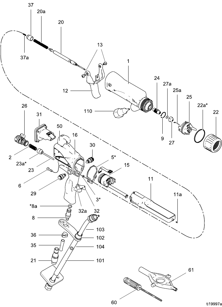
Parts
Smart Air-Assisted Spray Gun Assembly
Part No. H60M18 60 kV Electrostatic Air-Assisted Spray Gun, Series A, includes items 1–61
Part No. 24M508 Unshielded Waterborne Fluid Hose (101), sold separately
62 3A2497B

Parts
Part No. H60M18 60 kV Electrostatic Air-Assisted Spray Gun, Series A, includes items 1–61
Part No. 24M508 Unshielded Waterborne Fluid Hose (101), sold separately
Ref.
No.
Part No. Description Qty
124N745 BODY, gun 1
2 185116 SPRING, compression 1
3* 188749 PACKING, u-cup 1
5* 24N699 GASKET, body 1
624N740
SCREW, hex socket;
package of 2
1
724N742 BRACKET 1
8 249323 VALVE, exhaust 1
8a* 112085 O-RING 1
924N747
RING, conductive 1
11 24N662 POWER SUPPLY, 60 kV gun 1
11a 24N979 SPRING 1
12 24N663 TRIGGER; includes item 13 1
13 24A445 SCREW, trigger; package of 2 1
15 24N664 See
Alternator Assembly, page 67
1
16 24P745 HANDLE, smart; 60 kV AA gun 1
20 24N781 NEEDLE ASSEMBLY; includes
item 20a
1
20a 24N782 SPRING, fluid needle 1
21 24N626 SWIVEL, air inlet; M12 x 1/4
npsm(m); left-hand thread
1
22 24N793 RING, retainer; includes 22a 1
22a* 198307 PACKING, u-cup; UHMWPE;
part of 22
1
23 24N633 VALVE, air 1
23a* 276733 SEAL 1
24 24N725 HOUSING, seat 1
25 24N727 See Air Cap Assembly, page 70 1
25a 24N643 ELECTRODE; package of 5 1
26 24N632 See ES On-Off Valve Assembly,
page68
1
27 AEMxxx
AEFxxx
TIP ASSEMBLY; customer’s
choice; includes item 27a
1
Ref.
No.
Part No. Description Qty
27a 183459 GASKET, tip 1
29 24N792 ATOMIZING AIR
ADJUSTMENT VALVE
1
30 24N634 See Fan Air Valve Assembly,
page 69
1
31 24N756 See Smart Module Assembly,
page 70
1
32 24E404 STOP, trigger; includes item 32a 1
32a ——— PIN, dowel 1
35 185103 TUBE, exhaust; 1/4 in. (6 mm)
ID (shipped loose)
1
36 110231 CLAMP 1
37 24N785 CAP, spring; includes item 37a 1
37a 197624 SPRING, compression 1
38 24N786 PLUG, fan control; option,
shipped loose for use in place
of item 29
1
40 245265 CIRCUIT, flexible 1
50 24N783 HOOK; includes screw 1
51 112080 TOOL, needle (shipped loose) 1
54 24N604 COVER, gun; package of 10 1
55▲ 222385 CARD, warning (not shown) 1
56▲ 186118 SIGN, warning (not shown) 1
57 116553 GREASE, dielectric; 1 oz (30
ml) tube(notshown)
1
58 117824 GLOVE, conductive, medium;
package of 12; also available
in small (117823) and large
(117825)
1
60 107460 TOOL, wrench, ball end
(shipped loose)
1
61 276741 MULTI-TOOL (shipped loose) 1
101 24M508 HOSE, unshielded, waterborne
fluid; includes 101a
1
101a ——— CONNECTOR, barrel 1
▲ Replacement Danger and Warning labels, tags,
and cards are available at no cost.
*T
hese parts are included in Air Seal Repair Kit
24N789 (purchase separately).
Parts labeled — — — are not available separately.
3A2497B 63
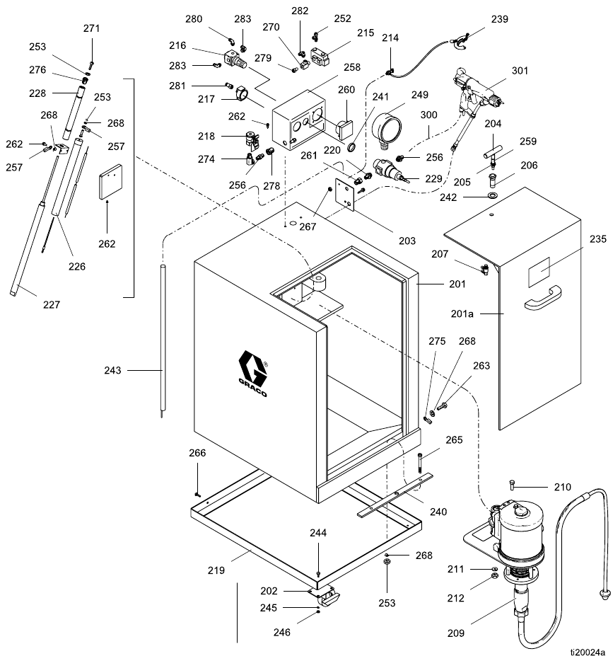
Parts
Isolation Enclosure
Part No. 24N550 Waterborne Isolation Enclosure, for use with unshielded waterborne fluid hose; includes
items 201–286
64 3A2497B

Parts
Part No. 24N550 Waterborne Isolation Enclosure, for use with unshielded waterborne fluid hose; includes
items 201–286
Ref.
No.
Part No. Description Qty
201 ——— CABINET; includes 201a 1
201a 15A947 DOOR, cabinet 1
202 116993 CASTER, brake 4
203 ——— PLATE 1
204 15A551 T-HANDLE, latch 1
205 15A545 STEM, handle, door 1
206 15A524 HOUSING, latch 1
207 113061 SWITCH, push, air 1
209 24N548 PUMP; see 3A0732 1
210 ——— SCREW, hex hd cap; 5/16–18 x
5.5 in. (140 mm)
4
211 ——— WASHER, plain; 0.344 in. ID 4
212 ——— NUT, lock; 5/16–18 4
214 104029 LUG, ground 1
215 116989 VALVE, air 1
216 111804 REGULATOR, air 1
217 113060 GAUGE, air; 1/8 npt 1
218 116473 BALL VALVE; 1/4 npt(f) 1
219 233824 CART 1
220 162453 NIPPLE; 1/4 npt x 1/4 npsm 1
226 190410 RESISTOR, bleed 1
227 116988 CYLINDER ROD 1
228 15A518 HOUSING, cylinder rod 1
229 104267 REGULATOR, air 1
230 ——— BUSHING; plastic; 3/4 x 1/2 npt 1
235▲ 15A682 LABEL, warning 1
238 114958 STRAP, tie 5
239 222011 GROUNDWIRE;25ft(7.6m) 1
240 234018 STRIP, grounding; aluminum 1
241 110209 NUT, regulator 11
Ref.
No.
Part No. Description Qty
242 114051 WASHER, shim, ;atch 1
243 210084 ROD, ground 1
244 ——— SCREW, hex hd; 1/4–20 x 5/8
in. (16 mm)
16
245 ——— WASHER,plain;1/4in.(6mm) 16
246 ——— NUT, hex; 1/4–20 16
247 107257 SCREW, thread-forming 1
248 ——— TUBE; 1/4 in. (6 mm) OD; nylon A/R
249 160430 GAUGE, air 1
251 ——— WIRE, 10 gauge; green with
yellow stripe
1
252 ——— CONNECTOR, swivel tee; 1/8
npt x 5/32 in. (4 mm) tube
1
253 ——— NUT, hex; 10–32 5
256 162449 NIPPLE, reducing; 1/2 npt x 1/4
npt
2
257 101874 TERMINAL, ring 5
258 116990 BOX, control 1
259 113983 RING, retaining; 1/2 in. (13 mm) 1
260 237933 METER, 0–90 kV 1
261 113336 ADAPTER; 1/4 npt 1
262 ——— SCREW, pan hd; 10–32 x 5/8 in.
(16 mm)
2
263 ——— SCREW, pan hd; 10–32 x 1/4 in.
(6 mm)
1
264 ——— HOLDER, tie 3
265 ——— SCREW, button hd; 10–24 x 1.5
in. (38 mm)
2
266 ——— SCREW, button hd; 10–32 x 1.0
in. (25 mm)
4
267 ——— NUT, hex; M5 x 0.8 1
268 ——— WASHER, lock; no. 10 9
3A2497B 65

Parts
Ref.
No.
Part No. Description Qty
270 116991 TEE, run, manifold 1
271 203953 SCREW, hex hd cap with patch;
10–24 x 3/8 in. (10 mm)
1
272 ——— WIRE, 14 gauge; red A/R
273 ——— WIRE, ground, 14 gauge; green
with yellow stripe
A/R
274 155541 UNION, swivel; 1/4 npt 1
275 114261 TERMINAL, ring; no. 10 1
276 15A780 PLUG, hex hd 1
278 117314 BULKHEAD CONNECTOR; 1/4
npt
1
279 113319 CONNECTOR, tube; 1/4 npt x
3/8 in. (10 mm) OD tube
2
280 ——— ELBOW, tube 1
281 ——— FITTING, tube; 1/8 npt x 5/32 in.
(4 mm) OD tube
1
Ref.
No.
Part No. Description Qty
282 ——— SWIVEL, tube; 1/4 npt x 1/4 in.
(6 mm) OD tube
4
283 ——— SWIVEL, tube; 1/8 npt x 5/32 in.
(4 mm) OD tube
2
286 ——— TUBE; 3/8 in. (10 mm) OD A/R
300★ 235070 HOSE, air, grounded; 0.315 in.
(8 mm) ID; 1/4 npsm(f) x 1/4
npsm(f) left-hand thread; red
cover with stainless steel braid
ground path; 25 ft (7.6 m) long
1
H60T18 GUN; see Standard Air-Assisted
Spray Gun Assembly, page 60
1301★
H60M18 GUN; see Smart Air-Assisted
Spray Gun Assembly, page 62
1
▲ Replacement Danger and Warning labels, tags,
and cards are available at no cost.
★ The air hose (300) and gun (301) are not included
with the 24N550 Isolation Enclosure. They are shown
for illustrative purposes only. See page 3 for a list of
models which include an air hose and gun.
66 3A2497B
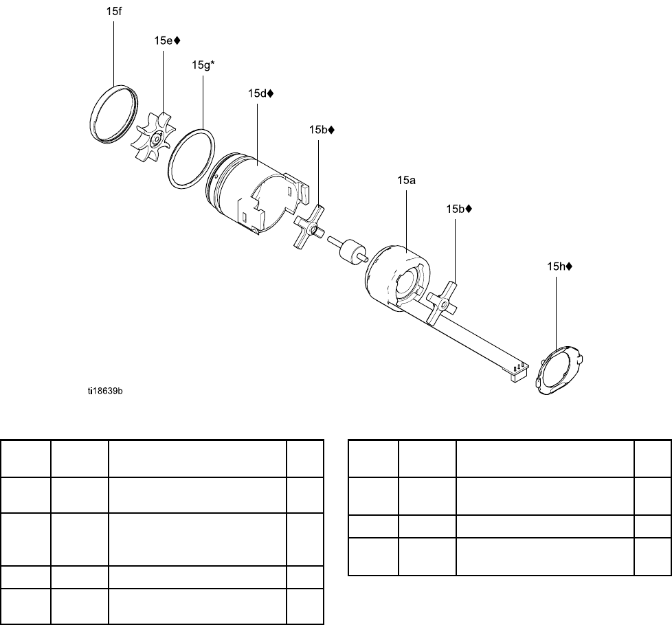
Parts
Alternator Assembly
Part No. 24N664 Alternator Assembly
Ref.
No.
Part
No.
Description Qty
15a 24N705 COIL, alternator 1
15b♦ 24N706 BEARING KIT (includes two
bearings, item 15e fan, and
one item 15h clip)
1
15d♦ 24N707 HOUSING; includes item 15f 1
15e♦ ——— FAN; part of item 15b 1
Ref.
No.
Part
No.
Description Qty
15f ——— CAP, housing; part of item
15d
1
15g* 110073 O-RING 1
15h♦ 24N709 CLIP; package of 5 (one clip
included with item 15b)
1
*The
se parts are included in Air Seal Repair Kit
24N789 (purchase separately).
♦ These parts are included in Bearing Kit 24N706
(purchase separately).
Parts labeled — — — are not available separately.
3A2497B 67
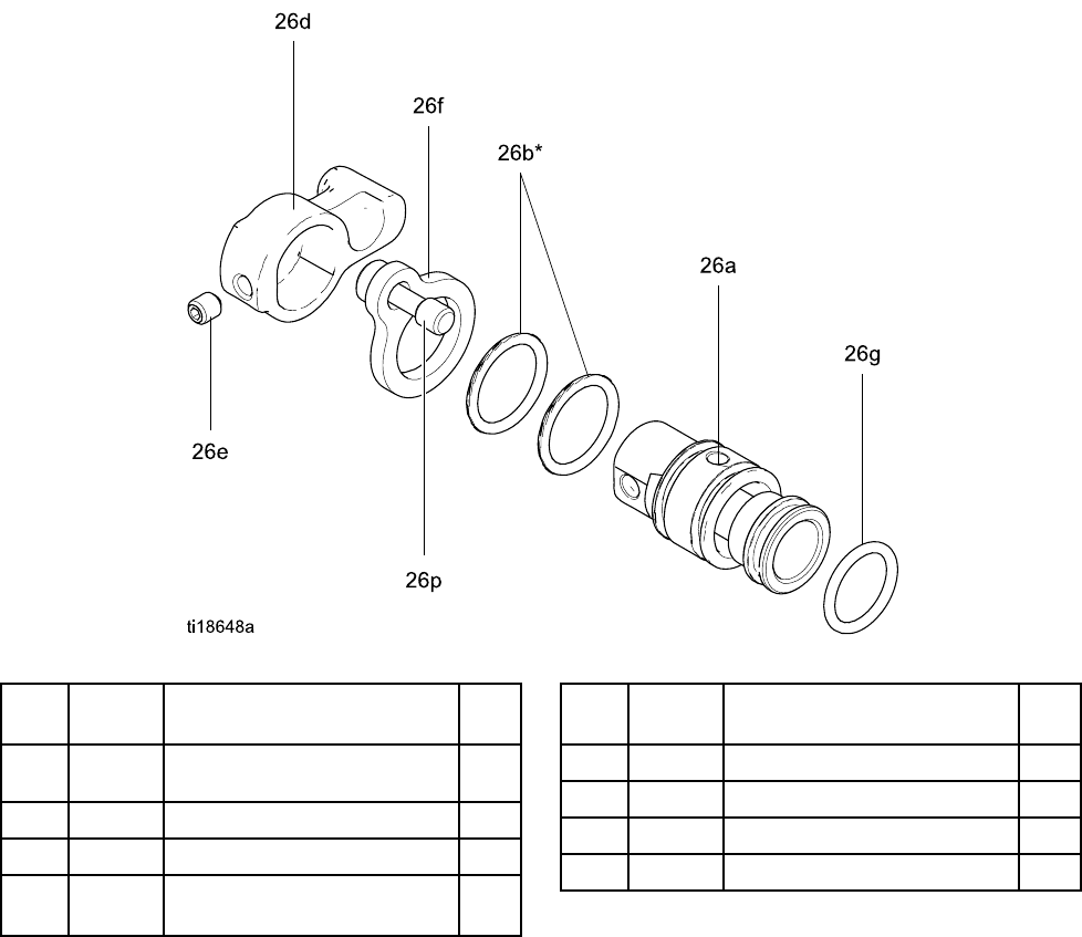
Parts
ES On-Off Valve Assembly
Part No. 24N632 ES On-Off Valve Assembly
Ref.
No.
Part No. Description Qty
26a ——— HOUSING, valve 1
26b* 15D371O-RING 2
26c ——— PISTON, valve 1
26d 24N650 LEVER, ES on-off; includes
item 26e
1
Ref.
No.
Part No. Description Qty
26e ——— SCREW, set, socket head 2
26f 24N631 PLATE, retaining 1
26g* 113746 O-RING 1
26p ——— SCREW, captive 1
* These parts are included in Air Seal Repair Kit
24N789 (purchase separately).
Parts labeled — — — are not available separately.
68 3A2497B
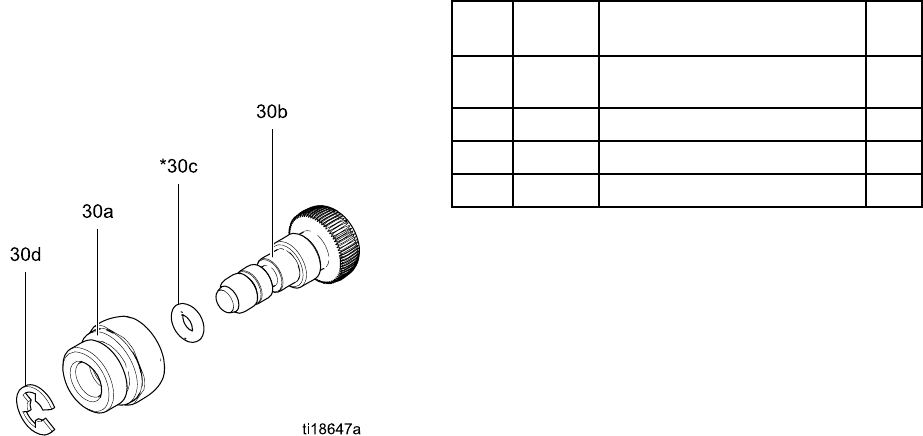
Parts
Fan Air Valve Assembly
Part No. 24N634 Fan Air Valve Assembly
Ref.
No.
Part No. Description Qty
30a ——— NUT, valve 1
30b ——— STEM, valve 1
30c* 111504 O-RING 1
30d 24N646 RING, retaining; package of 6 1
* These parts are included in Air Seal Repair Kit
24N789 (purchase separately).
Parts labeled — — — are not available separately.
3A2497B 69
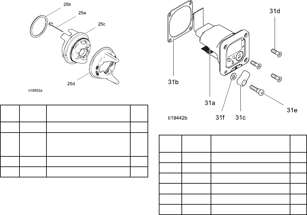
Parts
Air Cap Assembly
Part No. 24N727 Air Cap Assembly
Ref.
No.
Part No. Description Qty
25a 24N643 ELECTRODE; package of 5 1
25b 24N734 O-RING; ptfe; package of 5
(also available in package of
10; order 24E459)
1
25c ——— AIR CAP 1
25d 24N726 GUARD, tip, orange 1
Parts labeled — — — are not available separately.
Smart Module Assembly
Part No. 24N756 Smart Module Assembly
Ref.
No.
Part No. Description Qty
31a ——— CARTRIDGE 1
31b 24P433 GASKET 1
31c 24N787 SWITCH, ES HI/LO 1
31d♦ ——— SCREW 3
31e♦ ——— SCREW, pivot 1
31f 112319 O-RING 1
Parts labeled — — — are not available separately.
♦ThesepartsareincludedinSmartModuleScrew
Kit 24N757 (purchase separately).
70 3A2497B

Spray Tip Selection Chart
Spray Tip Selection Chart
AEM Fine Finish Spray Tips
Recommended for high finish quality applications at low and medium pressures. Order desired tip, Part No.
AEMxxx, where xxx = 3–digit number from the matrix below.
Fluid Output
fl oz/min (l/min)
Maximum Pattern Width at 12 in. (305 mm)
in. (mm)
2–4
(50–
100)
4–6
(100–
150)
6-8
(150-
200)
8-10
(200-
250)
10-12
(250-
300)
12-14
(300-
350)
14-16
(350-
400)
16-18
(400-
450)
Orifice
Size
in.
(mm)
at 600
psi (4.1
MPa,
41 bar)
at 1000
psi (7.0
MPa,
70 bar) Spray Tip
†0.007
(0.178)
4.0
(0.1)
5.2
(0.15)
107 207 307
†0.009
(0.229)
7.0
(0.2)
9.1
(0.27)
209 309 409 509 609
†0.011
(0.279)
10.0
(0.3)
13.0
(0.4)
211 311 411 511 611 711
0.013
(0.330)
13.0
(0.4)
16.9
(0.5)
213 313 413 513 613 713 813
0.015
(0.381)
17.0
(0.5)
22.0
(0.7)
215 315 415 515 615 715 815
0.017
(0.432)
22.0
(0.7)
28.5
(0.85)
217 317 417 517 617 717
0.019
(0.483)
28.0
(0.8)
36.3
(1.09)
319 419 519 619 719
0.021
(0.533)
35.0
(1.0)
45.4
(1.36)
421 521 621 721 821
0.023
(0.584)
40.0
(1.2)
51.9
(1.56)
423 523 623 723 823
0.025
(0.635)
50.0
(1.5)
64.8
(1.94)
425525625725825
0.029
(0.736)
68.0
(1.9)
88.2
(2.65)
829
0.031
(0.787)
78.0
(2.2)
101.1
(3.03)
431 631 831
0.033
(0.838)
88.0
(2.5)
114.1
(3.42)
833
0.037
(0.939)
108.0
(3.1)
140.0
(4.20)
737
0.039
(0.990)
118.0
(3.4)
153.0
(4.59)
539
* Tips are tested in water.
Fluid output (Q) at other pressures (P) can be calculated by this formula: Q = (0.041) (QT) where QT =
fluid output (fl oz/min) at 600 psi from the above table for the selected orificesize.
† These tip sizes include a 150 mesh filter.
3A2497B 71

Spray Tip Selection Chart
AEF Fine Finish Pre-Orifice Spray
Tips
Recommended for high finish quality applications at low and medium pressures. AEF tips have a pre-orifice
that assists in atomizing sheer thinning materials, including lacquers.
Order desired tip, Part No. AEFxxx, where xxx = 3–digit number from the matrix below.
Fluid Output
floz/min(l/min)
Maximum Pattern Width at 12 in. (305 mm)
in. (mm)
6-8 (150-
200)
8-10
(200-250)
10-12
(250-300)
12-14
(300-350)
14-16
(350-400)
16-18
(400-450)
Orifice
Size
in. (mm) at 600 psi
(4.1 MPa,
41 bar)
at 1000
psi (7.0
MPa, 70
bar) Spray Tip
† 0.010
(0.254)
9.5 (0.28)12.5
(0.37)
310 410 510 610 710
0.012
(0.305)
12.0
(0.35)
16.0
(0.47)
312 412 512 612 712 812
0.014
(0.356)
16.0
(0.47)
21.0
(0.62)
314 414 514 614 714 814
0.016
(0.406)
20.0
(0.59)
26.5
(0.78)
416 516 616 716
* Tips are tested in water.
Fluid output (Q) at other pressures (P) can be calculated by this formula: Q = (0.041) (QT) where QT =
fluid output (fl oz/min) at 600 psi from the above table for the selected orificesize.
† These tip sizes include a 150 mesh filter.
723A2497B
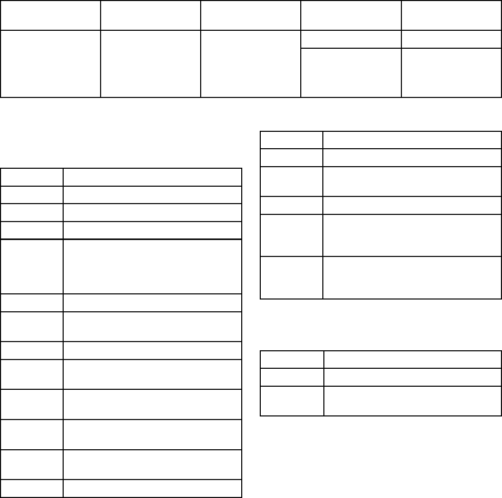
Repair Kits, Related Manuals, and Accessories
Repair Kits, Related
Manuals, and Accessories
Gun Part No. Description Manual Description Repair Kits Repair Kit
Description
24N789 Air Seal Repair Kit
All guns in this
manual.
60 kV Waterborne
Air-Assisted Spray
Guns
Electrostatic
Waterborne
Air-Assisted
Spray Guns,
Instructions-Parts
24N706 Alternator Bearing
Repair Kit
Gun Accessories
Part No. Description
105749 Cleaning Brush.
111265 Non-silicone Lubricant, 4 oz (113 g).
116553 Dielectric Grease. 1 oz (30 ml)
24N319 Round Spray Kit. To convert a
standard air—assisted spray gun to
a round spray air cap. See manual
3A2499.
24N604 Gun Covers. Box of 10.
24N758 Display Covers. Keeps Smart display
clean. Package of 5.
24P170 Metal Trigger Kit.
24P172 Quick Adjust Valve. For quick
change of fan size.
185105 Non-swivel Air Inlet; 1/4–18 npsm(m)
(left-hand thread)
24N642 Air Inlet Ball Swivel; 1/4–18 npsm(m)
(left-hand thread)
185493 Air Hose Adapter; 1/4 npt(m) x
1/4–18 npsm(m) (left-hand thread)
112534 Air Line Quick Disconnect Fitting.
Operator Accessories
Part No. Description
117823 Conductive Gloves, box of 12 (small)
117824 Conductive Gloves, box of 12
(medium)
117825 Conductive Gloves, box of 12 (large)
24N520 Comfort Grip. Snap-on grip
increases handle size to reduce
operator fatigue. Medium size.
24N521 Comfort Grip. Snap-on grip
increases handle size to reduce
operator fatigue. Large size.
System Accessories
Part No. Description
222011 Ground Wire and Clamp.
186118 English Warning Sign. Available at
no charge from Graco.
3A2497B 73

Repair Kits, Related Manuals, and Accessories
Hoses
Grounded Air Hoses
100 psi (0.7 MPa, 7 bar) Maximum Working Pressure
0.315 in. (8 mm) ID; 1/4 npsm(f) x 1/4 npsm(f)
left-hand thread
Part No. Description
Grounded Air Hose with stainless steel braid
ground path (Red)
235068 6ft(1.8m)
235069 15 ft (4.6 m)
235070 25 ft (7.6 m)
235071 36 ft (11 m)
235072 50 ft (15 m)
235073 75 ft (23 m)
235074 100 ft (30.5 m)
Test Equipment
Part No. Description
241079 Megohmmeter. 500 V output,
0.01–2000 megohms. Use for
ground continuity and gun resistance
tests.Not for use in hazardous areas.
245277 Test Fixture, High Voltage Probe,
and kV Meter. Use to test the
electrostatic voltage of the gun, and
the condition of the alternator and
power supply when being serviced.
See manual 309455.
743A2497B
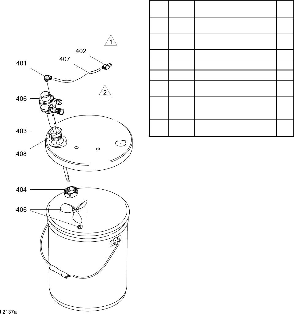
Repair Kits, Related Manuals, and Accessories
245895 Agitator Kit
To keep fluid mixed and prevent settling out. Includes
items 401–408.
Ref.
No.
Part No. Description Qty
401 112698 ELBOW, swivel; 1/8 npt(m) x
1/4 in. (6 mm) OD tube
1
402 114158 FITTING, adapter, Y; 1/4 in. (6
mm) OD tube; mxfxf
1
403 193315 COLLAR, mounting, agitator 1
404 193316 NUT, collar, agitator 1
405 197298 COVER, pail; 5 gal. (19 liter) 1
406 224571 AGITATOR; see manual
306565
1
407 pur-
chase
locally
TUBE, nylon; 1/4 in. (6 mm)
OD; 4 ft (1.22 m)
1
408 110272 SCREW, set, socket hd;
1/4–20 x 1/4 in. (6 mm)
1
3A2497B 75
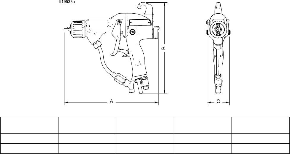
Dimensions
Dimensions
Figure 45
Gun Model A, in. (mm) B, in. (mm) C, in. (mm) Weight without
bracket, oz (g)
H60T18 10.7 (272) 8.9 (226) 2.4 (61) 22.0 (623)
H60M18 10.8 (274) 9.6 (244) 2.4 (61) 24.4 (692)
76 3A2497B

Technical Data
Technical Data
Electrostatic Air—Assisted Spray Waterborne Guns
U.S. Metric
Maximum Working Fluid Pressure 3000 psi 21 MPa, 210 bar
Maximum Working Air Pressure 100 psi 0.7 MPa, 7.0 bar
Minimum Air Pressure at Gun Inlet 45 psi 0.32 MPa, 3.2 bar
Maximum Fluid Operating
Temperature
120°F 48°C
Short Circuit Current Output 125 microamperes
Voltage Output Energy 0.35 J with fluid hose 24M508 installed.
H60T18: 60kV
H60M18: 30–60 kV
Sound Power (measured per ISO
Standard 9216)
at 40 psi: 90.4 dB(A)
at 100 psi: 105.4 dB(A)
at 0.28 MPa, 2.8 bar: 90.4 dB(A)
at 0.7 MPa, 7.0 bar: 105.4 dB(A)
Sound Pressure (measured 1 m
from gun)
at 40 psi: 87.0 dB(A)
at 100 psi: 99.0 dB(A)
at 0.28 MPa, 2.8 bar: 87.0 dB(A)
at 0.7 MPa, 7.0 bar: 99.0 dB(A)
Air Inlet Fitting 1/4 npsm(m) left-hand thread
Fluid Inlet Fitting Custom inlet for Graco waterborne fluid hose.
Isolation Enclosure Air Inlet Fitting 1/4 npt
Isolation Enclosure Fluid Inlet
Fitting
3/8 in. OD tube fitting 10 mm OD tube fitting
Wetted Parts Gun: Stainless Steel, PEEK, UHMWPE, Fluoroelastomer, Acetal,
Nylon, Polyethylene, Tungsten Wire
Waterborne Fluid Hose: PTFE
Suction Tube: Polyethylene, Stainless Steel
Merkur Pump: See manual 3A0732.
3A2497B 77

Graco Pro Xp Warranty
Graco warrants all equipment referenced in this document which is manufacturedbyGracoandbearingitsnametobe
free from defects in material and workmanship on the date of sale to the original purchaser for use. With the exception of
any special, extended, or limited warranty published by Graco, Graco will,foraperiodoftwelvemonthsfromthedate
of sale, repair or replace any part of the equipment determined by Graco to be defective. However, any deficiency in
the barrel, handle, trigger, hook, internal power supply, and alternator (excluding turbine bearings) will be repaired or
replaced for thirty-six months from the date of sale. This warranty applies only when the equipment is installed, operated
and maintained in accordance with Graco’s written recommendations.
This warranty does not cover, and Graco shall not be liable for general wear and tear, or any malfunction, damage or
wear caused by faulty installation, misapplication, abrasion, corrosion, inadequate or improper maintenance, negligence,
accident, tampering, or substitution of non-Graco component parts. Nor shall Graco be liable for malfunction, damage
or wear caused by the incompatibility of Graco equipment with structures, accessories, equipment or materials not
supplied by Graco, or the improper design, manufacture, installation, operation or maintenance of structures, accessories,
equipment or materials not supplied by Graco.
This warranty is conditioned upon the prepaid return of the equipment claimed to be defective to an authorized Graco
distributor for verification of the claimed defect. If the claimed defect is verified, Graco will repair or replace free of charge
any defective parts. The equipment will be returned to the original purchaser transportation prepaid. If inspection of the
equipment does not disclose any defect in material or workmanship, repairs will be made at a reasonable charge, which
charges may include the costs of parts, labor, and transportation.
THIS WARRANTY IS EXCLUSIVE, AND IS IN LIEU OF ANY OTHER WARRANTIES, EXPRESS OR IMPLIED,
INCLUDING BUT NOT LIMITED TO WARRANTY OF MERCHANTABILITY OR WARRANTY OF FITNESS FOR A
PARTICULAR PURPOSE.
Graco’s sole obligation and buyer’s sole remedy for any breach of warranty shall be as set forth above. The buyer agrees
that no other remedy (including, but not limited to, incidental or consequential damages for lost profits, lost sales, injury to
person or property, or any other incidental or consequential loss) shall be available. Any action for breach of warranty
must be brought within two (2) years of the date of sale.
GRACO MAKES NO WARRANTY, AND DISCLAIMS ALL IMPLIED WARRANTIES OF MERCHANTABILITY AND
FITNESS FOR A PARTICULAR PURPOSE, IN CONNECTION WITH ACCESSORIES, EQUIPMENT, MATERIALS OR
COMPONENTS SOLD BUT NOT MANUFACTURED BY GRACO. These items sold, but not manufactured by Graco
(such as electric motors, switches, hose, etc.), are subject to the warranty, if any, of their manufacturer. Graco will provide
purchaser with reasonable assistance in making any claim for breach of these warranties.
In no event will Graco be liable for indirect, incidental, special or consequential damages resulting from Graco supplying
equipment hereunder, or the furnishing, performance, or use of any products or other goods sold hereto, whether due to a
breach of contract, breach of warranty, the negligence of Graco, or otherwise.
FOR GRACO CANADA CUSTOMERS
The Parties acknowledge that they have required that the present document, as well as all documents, notices and legal
proceedings entered into, given or instituted pursuant hereto or relating directly or indirectly hereto, be drawn up in
English. Les parties reconnaissent avoir convenu que la rédaction du présente document sera en Anglais, ainsi que
tous documents, avis et procédures judiciaires exécutés, donnés ou intentés, à la suite de ou en rapport, directement ou
indirectement, avec les procédures concernées.
Graco Information
For the latest information about Graco products, visit www.graco.com. For patent information, see www.graco.com/patents.
To place an order, contact your Graco Distributor or call to identify the nearest distributor.
Phone: 612-623-6921 or Toll Free: 1-800-328-0211 Fax: 612-378-3505
All written and visual data contained in this document reflects the latest product information available at the time of publication.
Graco reserves the right to make changes at any time without notice.
Original Instructions. This manual contains English, MM 3A2497
Graco Headquarters: Minneapolis
International Offices: Belgium, China, Japan, Korea
GRACO INC. AND SUBSIDIARIES • P.O. BOX 1441 • MINNEAPOLIS, MN 55440-1441 • USA
Copyright 2012, Graco Inc. All Graco manufacturing locations are registered to ISO 9001.
www.graco.com
Revised July 2013
