Graco 3A2989G Xm Pfp Users Manual 3A2989G, PFP, Repair Parts, (English)
2015-04-02
: Graco Graco-3A2989G-Xm-Pfp-Users-Manual-686257 graco-3a2989g-xm-pfp-users-manual-686257 graco pdf
Open the PDF directly: View PDF ![]() .
.
Page Count: 62
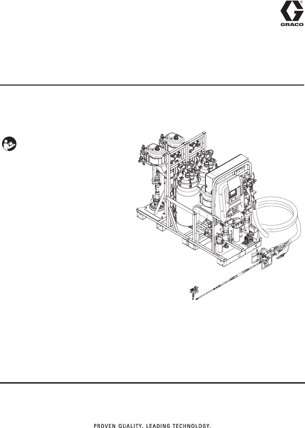
3A2989G
EN
Repair - Parts
XM PFP
For spraying two-component intumescent epoxies. For professional use only.
Not for use in explosive atmospheres or hazardous locations.
See page 3 for model information, including
maximum working pressure and approvals.
Important Safety Instructions
Read all warnings and instructions in all
supplied manuals. Save all instructions.
WLD
23A2989G
Contents
Models . . . . . . . . . . . . . . . . . . . . . . . . . . . . . . . . . . . 3
Related Manuals . . . . . . . . . . . . . . . . . . . . . . . . . . . 3
Warnings . . . . . . . . . . . . . . . . . . . . . . . . . . . . . . . . . 4
Keep Components A and B Separate . . . . . . . . 6
Changing Materials . . . . . . . . . . . . . . . . . . . . . . . 6
Components A and B . . . . . . . . . . . . . . . . . . . . . 6
Component Identification . . . . . . . . . . . . . . . . . . . . 6
Grounding . . . . . . . . . . . . . . . . . . . . . . . . . . . . . . . . 6
Pressure Relief Procedure . . . . . . . . . . . . . . . . . . . 7
Troubleshooting . . . . . . . . . . . . . . . . . . . . . . . . . . . 8
Repair . . . . . . . . . . . . . . . . . . . . . . . . . . . . . . . . . . . . 9
Replace Air Filter Element . . . . . . . . . . . . . . . . . 9
User Interface/Control Box . . . . . . . . . . . . . . . . 10
Junction Box . . . . . . . . . . . . . . . . . . . . . . . . . . . 15
Air Controls . . . . . . . . . . . . . . . . . . . . . . . . . . . . 17
Dosing Valve Assembly . . . . . . . . . . . . . . . . . . 19
Sensors . . . . . . . . . . . . . . . . . . . . . . . . . . . . . . . 20
Pump Assembly (System Module) . . . . . . . . . . 21
Pail Feed RAM Pump Assembly (Feed Module) 22
Solvent Pump . . . . . . . . . . . . . . . . . . . . . . . . . . 22
Heaters . . . . . . . . . . . . . . . . . . . . . . . . . . . . . . . 23
Replace Radar Level Sensor . . . . . . . . . . . . . . 24
Set Up a New Guided Radar Level Sensor . . . 25
Electrical Schematics . . . . . . . . . . . . . . . . . . . . . . 27
Simplified Electrical Schematic . . . . . . . . . . . . . 27
Parts . . . . . . . . . . . . . . . . . . . . . . . . . . . . . . . . . . . . 32
XM PFP System (262869, 24W626) . . . . . . . . . 32
Base System (262878, 24W648) Subassemblies 44
Technical Data . . . . . . . . . . . . . . . . . . . . . . . . . . . . 58
Notes . . . . . . . . . . . . . . . . . . . . . . . . . . . . . . . . . . . . 61
Graco Standard Warranty . . . . . . . . . . . . . . . . . . . 62
Graco Information . . . . . . . . . . . . . . . . . . . . . . . . 62
Models
3A2989G 3
Models
Related Manuals
Manuals are available at www.graco.com. Component
manuals in English:
Models
Maximum Fluid
Working Pressure
Maximum Air Working
Pressure Approvals
262869
24W626
A and B Materials:
6000 psi
(41 MPa, 414 bar)
Flushing Fluid:
4500 psi
(31 MPa, 310 bar)
Heating Fluid:
100 psi
(0.7 MPa, 7 bar)
Supply: 150 psi
(1.0 MPa, 10.3 bar)
Max. Setpoint: 100 psi
(0.7 MPa, 7 bar)
9902471
Certified to CAN/CSA C22.2 No. 88
Conforms to
UL 499
Manual Description
3A2776 XM PFP Setup - Operation
3A2988 XM PFP Mix Manifold Instructions - Parts
3A2799 XHF Spray Gun
Heaters
309524 Viscon
®
HP High Pressure Fluid Heater
Instructions - Parts
3A2954 Viscon HF High Flow, High Pressure Fluid
Heater Instructions - Parts
3A2824 Viscon LT Fluid Heater Instructions - Parts
Pumps, Motors, Supply Systems
308652 Husky
™
205 Air-Operated Diaphragm
Pumps Instructions - Parts
311238 NXT
®
Air Motor Instructions - Parts
311762 Xtreme
®
Lowers Instructions - Parts
312375 Check-Mate
®
Displacement Pumps
Instructions - Parts
312376 Check-Mate Pump Packages Instructions -
Parts
312792 Merkur
®
Pump Repair - Parts
312794 Merkur Pump Assembly Instructions - Parts
312796 NXT Air Motor Instructions - Parts
313526 Supply Systems Operation
313527 Supply Systems Repair - Parts
312374 Air Control Instructions - Parts
Accessories
332073 Hot Water Flush Kit Instructions
3A2987 Air Dryer Kit Instructions
Other
313342 Dosing Valve Instructions - Parts
306861 Ball Valves Instructions - Parts
307005 High Pressure Swivel Instructions - Parts
308169 Air Filters, Lubricators, and Kits Instructions
- Parts
407061 Simulation XM PFP Display Module
3A1244 Graco Control Architecture Module Pro-
gramming
Manual Description
Warnings
43A2989G
Warnings
The following warnings are for the setup, use, grounding, maintenance, and repair of this equipment. The exclama-
tion point symbol alerts you to a general warning and the hazard symbols refer to procedure-specific risks. When
these symbols appear in the body of this manual or on warning labels, refer back to these Warnings. Product-specific
hazard symbols and warnings not covered in this section may appear throughout the body of this manual where
applicable.
WARNINGWARNINGWARNING
WARNING
ELECTRIC SHOCK HAZARD
This equipment must be grounded. Improper grounding, setup, or usage of the system can cause
electric shock.
• Turn off and disconnect power at main switch before disconnecting any cables and before servicing
or installing equipment.
• Connect only to grounded power source.
• All electrical wiring must be done by a qualified electrician and comply with all local codes and
regulations.
SKIN INJECTION HAZARD
High-pressure fluid from gun, hose leaks, or ruptured components will pierce skin. This may look like just
a cut, but it is a serious injury that can result in amputation. Get immediate surgical treatment.
• Do not spray without tip guard and trigger guard installed.
• Engage trigger lock when not spraying.
• Do not point gun at anyone or at any part of the body.
• Do not put your hand over the spray tip.
• Do not stop or deflect leaks with your hand, body, glove, or rag.
•Follow the Pressure Relief Procedure when you stop spraying and before cleaning, checking, or
servicing equipment.
• Tighten all fluid connections before operating the equipment.
• Check hoses and couplings daily. Replace worn or damaged parts immediately.
FIRE AND EXPLOSION HAZARD
Flammable fumes, such as solvent and paint fumes, in work area can ignite or explode. To help prevent
fire and explosion:
• Use equipment only in well ventilated area.
• Eliminate all ignition sources; such as pilot lights, cigarettes, portable electric lamps, and plastic drop
cloths (potential static arc).
• Keep work area free of debris, including solvent, rags and gasoline.
• Do not plug or unplug power cords, or turn power or light switches on or off when flammable fumes
are present.
• Ground all equipment in the work area. See Grounding instructions.
• Use only grounded hoses.
• Hold gun firmly to side of grounded pail when triggering into pail. Do not use pail liners unless they
are antistatic or conductive.
•Stop operation immediately if static sparking occurs or you feel a shock. Do not use equipment
until you identify and correct the problem.
• Keep a working fire extinguisher in the work area.
BURN HAZARD
Equipment surfaces and fluid that’s heated can become very hot during operation. To avoid severe
burns:
• Do not touch hot fluid or equipment.
Warnings
3A2989G 5
MOVING PARTS HAZARD
Moving parts can pinch, cut or amputate fingers and other body parts.
• Keep clear of moving parts.
• Do not operate equipment with protective guards or covers removed.
• Pressurized equipment can start without warning. Before checking, moving, or servicing equipment,
follow the Pressure Relief Procedure and disconnect all power sources.
EQUIPMENT MISUSE HAZARD
Misuse can cause death or serious injury.
• Do not operate the unit when fatigued or under the influence of drugs or alcohol.
• Do not exceed the maximum working pressure or temperature rating of the lowest rated system
component. See Technical Data in all equipment manuals.
• Use fluids and solvents that are compatible with equipment wetted parts. See Technical Data in all
equipment manuals. Read fluid and solvent manufacturer’s warnings. For complete information
about your material, request MSDS from distributor or retailer.
• Do not leave the work area while equipment is energized or under pressure.
• Turn off all equipment and follow the Pressure Relief Procedure when equipment is not in use.
• Check equipment daily. Repair or replace worn or damaged parts immediately with genuine manu-
facturer’s replacement parts only.
• Do not alter or modify equipment. Alterations or modifications may void agency approvals and create
safety hazards.
• Make sure all equipment is rated and approved for the environment in which you are using it.
• Use equipment only for its intended purpose. Call your distributor for information.
• Route hoses and cables away from traffic areas, sharp edges, moving parts, and hot surfaces.
• Do not kink or over bend hoses or use hoses to pull equipment.
• Keep children and animals away from work area.
• Comply with all applicable safety regulations.
TOXIC FLUID OR FUMES HAZARD
Toxic fluids or fumes can cause serious injury or death if splashed in the eyes or on skin, inhaled, or
swallowed.
• Read MSDSs to know the specific hazards of the fluids you are using.
• Store hazardous fluid in approved containers, and dispose of it according to applicable guidelines.
PERSONAL PROTECTIVE EQUIPMENT
Wear appropriate protective equipment when in the work area to help prevent serious injury, including
eye injury, hearing loss, inhalation of toxic fumes, and burns. This protective equipment includes but is
not limited to:
• Protective eyewear, and hearing protection.
• Respirators, protective clothing, and gloves as recommended by the fluid and solvent manufacturer
SPLATTER HAZARD
Hot or toxic fluid can cause serious injury if splashed in the eyes or on skin. During blow off of platen,
splatter may occur.
• Use minimum air pressure when removing platen from drum.
WARNINGWARNINGWARNING
WARNING
Component Identification
63A2989G
Keep Components A and B
Separate
Changing Materials
Components A and B
IMPORTANT!
Material suppliers can vary in how they refer to plural
component materials.
Be aware that in this manual:
Component A refers to resin or major volume.
Component B refers to the hardener or minor volume.
This equipment doses the B component into the A com-
ponent flow. An integration hose must always be used
after the mix manifold and before the static mixer.
Component Identification
See XM PFP Operation manual for component identifi-
cation.
Grounding
Ground the electrical connection properly according to
local codes.
Cross-contamination can result in cured material in
fluid lines which could cause serious injury or damage
equipment. To prevent cross-contamination:
•Never interchange component A and component
B wetted parts.
• Never use solvent on one side if it has been con-
taminated from the other side.
NOTICE
Changing the material types used in your equipment
requires special attention to avoid equipment damage
and downtime.
• When changing materials, flush the equipment mul-
tiple times to ensure it is thoroughly clean.
• Always clean any fluid inlet strainers after flushing.
• Check with your material manufacturer for chemical
compatibility.
• When changing between epoxies and urethanes or
polyureas, disassemble and clean all fluid compo-
nents and change hoses. Epoxies often have
amines on the B (hardener) side. Polyureas often
have amines on the B (resin) side.
The equipment must be grounded to reduce the risk
of static sparking and electric shock. Electric or static
sparking can cause fumes to ignite or explode.
Improper grounding can cause electric shock.
Grounding provides an escape wire for the electric
current.
Pressure Relief Procedure
3A2989G 7
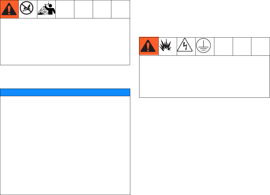
Pressure Relief Procedure
Follow the Pressure Relief Procedure whenever
you see this symbol.
1. Engage trigger lock.
2. If the system will be shut down for more than a few
hours, perform Park Fluid Pump Rods procedure
in XM PFP Operation manual to prevent fluid hard-
ening on the pump shaft.
3. Press (Stop button).
4. Slide the feed pump air supply valve (DF) and direc-
tor valve air supply valve (DA) to the OFF position.
5. If necessary to relieve tank air pressure: close both
feed system air control ball valves and back out the
air pressure regulator. Open the brass valves on the
tank lids for full tank de-pressurization. Pressure
gauge should read 0 psi.
6. Open mix manifold ball valves.
This equipment stays pressurized until pressure is
manually relieved. To help prevent serious injury
from pressurized fluid, such as skin injection,
splashing fluid and moving parts, follow the Pressure
Relief Procedure when you stop spraying and before
cleaning, checking, or servicing the equipment.
F
IG
. 1: Feed Pump Controls
TI19265a2
DF
DB
DA
DC
DD
DE
ti20104a
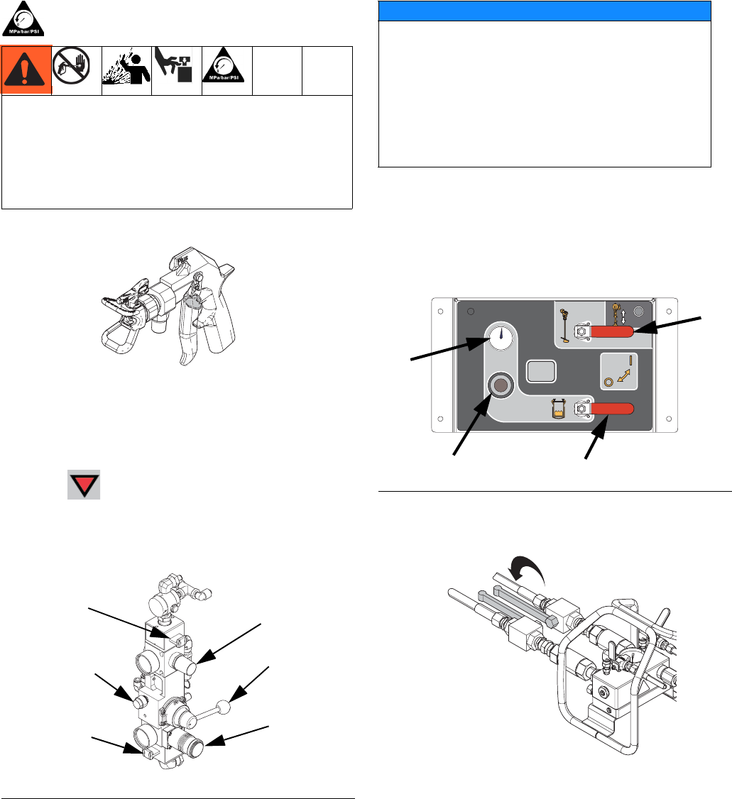
NOTICE
The material may expand when air pressure is
removed. This can cause the tank to overfill and
damage the parts attached to the tank lid. To pre-
vent overfilling the tank, never relieve air pressure
in the tank unless the tank is less than half full.
Verify tank material level on the user interface, see
Appendix A - User Interface Display section in
XM PFP Operation manual.
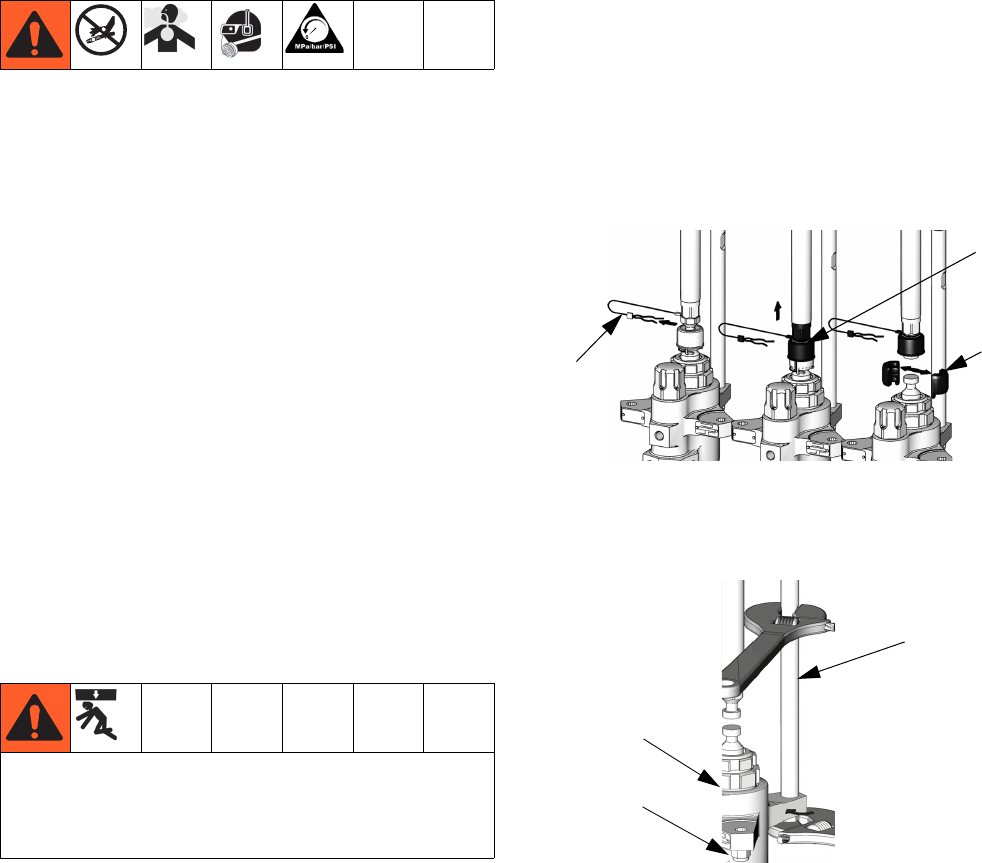
F
IG
. 2
FEED PUMP
BYPASS
ti20127a
ti20128a
Troubleshooting
83A2989G
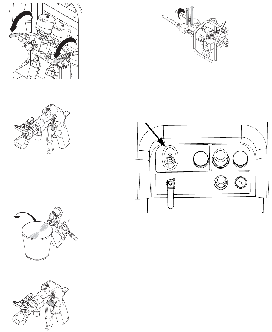
7. Open recirculation ball valves.
8. Disengage trigger lock.
9. Hold a metal part of the gun firmly to a grounded
metal pail. Trigger gun to relieve pressure in mate-
rial hoses. Use a pail lid with a hole to dispense
through. Seal around hole and gun with a rag to pre-
vent splash back.
10. Engage trigger lock.
11. Close mix manifold material ball valves.
12. Perform Flush Mixed Material procedure in XM
PFP Operation manual to prevent mixed material
curing in the system and to relieve pressure in the
solvent lines.
13. Close metering pump air supply ball valve.
14. If the system will be shutdown for more than a few
hours, fill pump A and B packing nuts with throat
seal liquid (TSL
™
).
NOTE: Fluid pressure in the system is now relieved.
Troubleshooting
See XM PFP Operation manual 3A2776 for trouble-
shooting details.
WLD
TI19265a1
TI1953a
TI19265a2
ti20129a
Repair
3A2989G 9
Repair
Follow Pressure Relief Procedure on page 7 if service
time may exceed pot life time, before servicing fluid
components, and before transporting sprayer.
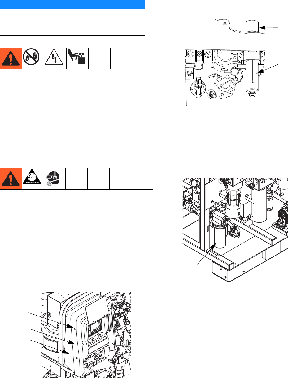
Replace Air Filter Element
There are two air filters on the system: the inlet air regu-
lator filter on the air controls and the main air inlet mani-
fold filter. Check filters weekly and replace element as
needed.
Both Filters
1. Close main air shutoff valve on air supply line and
on system. Depressurize air line.
Control Air Regulator Filter
2. Remove four nuts (21) and then remove front and
rear shrouds (19, 20).
3. Unscrew filter bowl from inlet air regulator (601d).
4. Remove and replace element.
5. Screw filter bowl on securely.
6. Replace front and rear shrouds (19, 20) using four
nuts (21).
Main Air Inlet Manifold Filter
2. Unscrew filter bowl collar from main air inlet
filter (14).
3. Remove and replace filter element (701a). See Air
Filter (24P899), page 49.
4. Reassemble filter bowl.
NOTICE
Do not use air motor lift rings to lift the entire
assembly. This will damage the system. The sys-
tem must be lifted from the bottom.
To reduce the risk of serious injury, do not service air
filter until air line is depressurized. Removing a pres-
surized air filter bowl could cause serious injury.
21
20
19
ti19926a1
Filter Bowl
and Element
r_312359_313289_15
601d
14
ti199526a1
Repair
10 3A2989G
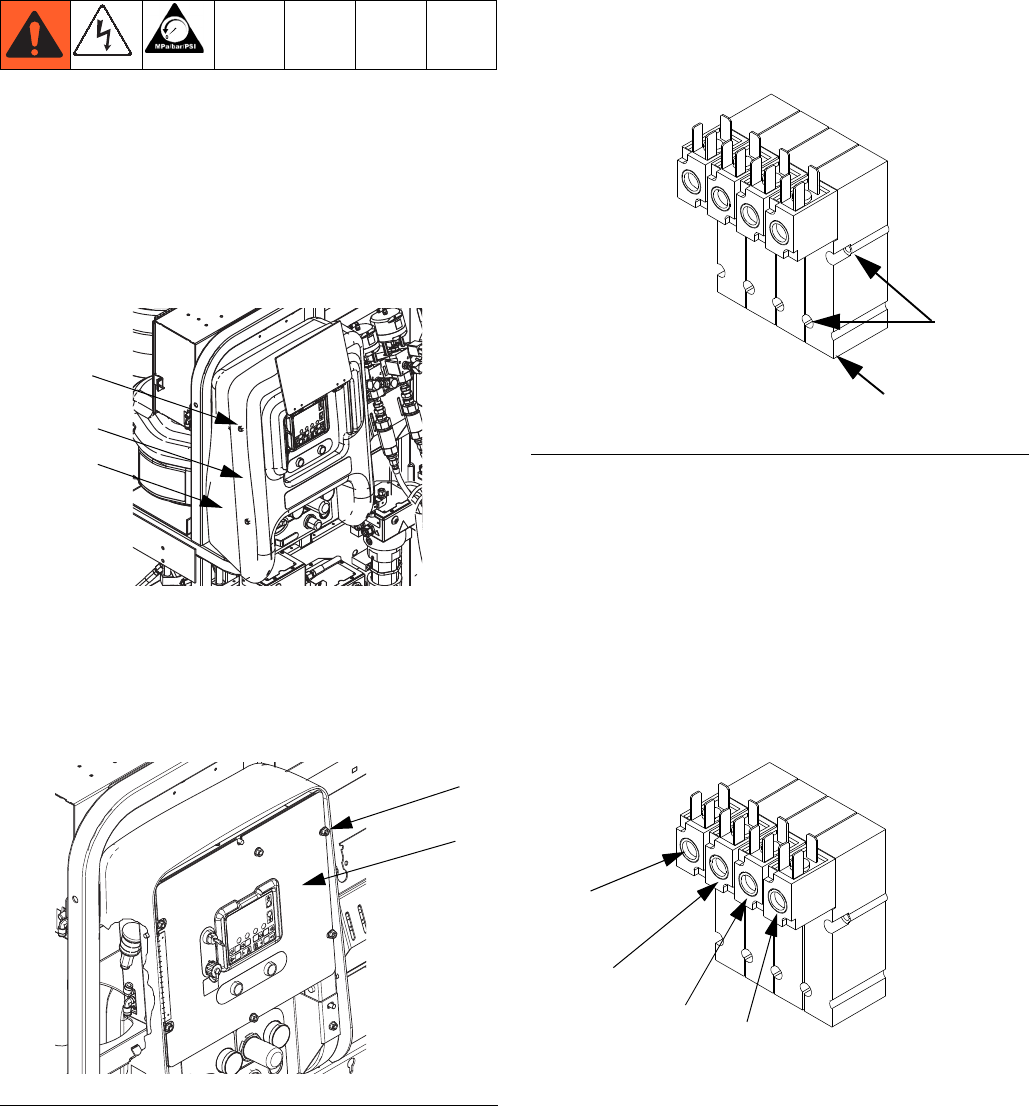
User Interface/Control Box
Remove Shroud and Front Panel of Control
Box
1. Close main air shutoff valve on air supply line and
on system. Depressurize air line.
2. Remove four nuts (21) and then remove front and
rear shrouds (19, 20).
3. Disconnect power.
4. Remove four nuts (17); leave two nuts on left side of
panel tight. Open front panel of control box (16).
See F
IG
. 3.
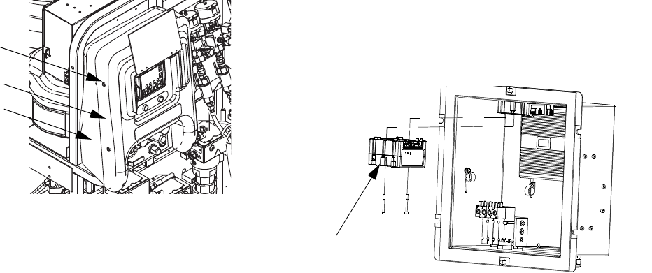
Replace Single Solenoid Module
1. Remove Shroud and Front Panel of Control Box,
see page 10.
2. Disconnect solenoid cable connector (542) from the
solenoid (509a) being replaced.
3. Remove two screws (509b) from the solenoid being
replaced then remove solenoid (509a). See F
IG
. 4.
4. Use screws (509b) to install new solenoid (509a).
5. Reconnect solenoid cable connectors (542). See
Control Box (255771) on page 47.
NOTE:
From left to right, solenoid functions are as follows:
• Dosing valve A (DVA) (normally open)
• Dosing valve B (DVB) (normally open)
• Pump A (PA) (normally closed)
• Pump B (PA) (normally closed)
F
IG
. 3
21
20
19
ti19926a1
17
16
ti20158b1
F
IG
. 4
r_xm1a00_312359_313289_9_3
509b
509a
DVA
DVB
PA
PB
r_xm1a00_312359_313289_9_3
Repair
3A2989G 11
Update USB Module Software
1. Remove four nuts (21) and then remove front and
rear shrouds (19, 20).
2. Use software token 16P644. See Graco Control
Architecture
™
Module Programming manual for
instructions.
NOTE: Upgrade all modules in the system to the
software version on the token, even if you are
replacing only one or two modules. Different soft-
ware versions may not be compatible.
All data in the module may be reset to factory
default settings. Record all settings and user prefer-
ences before the upgrade, for ease of restoring
them following the upgrade.
The latest software version for each system can be
found at Tech Support at www.graco.com.
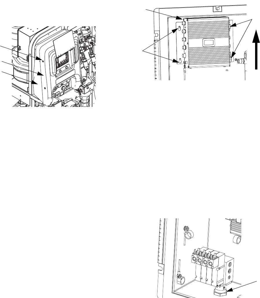
Replace USB Module
1. Remove Shroud and Front Panel of Control Box,
see page 10.
2. Disconnect CAN cables and USB cable from USB
module (519).
3. Remove two mounting screws from USB module
and remove module from base.
4. Follow steps in reverse order to install new USB
module.
5. Load software. See Update USB Module Soft-
ware.
21
20
19
ti19926a1
519
r_312359_313289_23a
Repair
12 3A2989G
Update Fluid Control Module (FCM)
Software
1. Remove four nuts (21) and then remove front and
rear shrouds (19, 20).
2. Use software token 16P644. See Graco Control
Architecture
™
Module Programming manual for
instructions.
NOTE: Upgrade all modules in the system to the
software version on the token, even if you are
replacing only one or two modules. Different soft-
ware versions may not be compatible.
All data in the module may be reset to factory
default settings. Record all settings and user prefer-
ences before the upgrade, for ease of restoring
them following the upgrade.
The latest software version for each system can be
found at Tech Support at www.graco.com.
Replace Fluid Control Module (FCM)
NOTE:
The USB module does not need to be removed prior to
replacing the FCM.
1. Remove Shroud and Front Panel of Control Box,
see page 10.
2. Remove all cables from FCM (518). Take note of
cable locations.
3. Loosen four mounting screws (535).
4. Slide FCM up and out of keyhole slots.
5. Follow steps in reverse order to install new FCM.
6. Load software. See Update Fluid Control Module
(FCM) Software.
7. Most of the system configuration is stored in the
FCM. Use the display to change the configuration to
the values in the old FCM. See XM PFP operation
manual for instructions.
Replace Alarm
1. Remove Shroud and Front Panel of Control Box,
see page 10.
2. Disconnect alarm wires from alarm (517).
3. Unscrew alarm (517) and replace.
4. Screw in new alarm. Reconnect alarm wires.
5. Reinstall front panel of control box and reinstall
shrouds.
21
20
19
ti19926a1
518
535
535
r_312359_313289_26
517
r_312359_313289_22
Repair
3A2989G 13
Display
Upgrade Software
Use software token 16P644. See Graco Control Archi-
tecture
™
Module Programming manual for instructions.
NOTE: Upgrade all modules in the system to the
software version on the token, even if you are
replacing only one or two modules. Different soft-
ware versions may not be compatible.
All data in the module may be reset to factory
default settings. Record all settings and user prefer-
ences before the upgrade, for ease of restoring
them following the upgrade.
The latest software version for each system can be
found at Tech Support at www.graco.com.
1. Remove Shroud and Front Panel of Control Box,
see page 10.
2. Remove four screws (512) then remove access
cover (511).
3. Insert and press token (T) firmly into slot.
NOTE:
There is no preferred orientation of token.
4. Turn power on.
5. The red indicator light (L) will flash until new soft-
ware is completely loaded.
6. Turn power off.
7. Remove token (T).
8. Use screws (512) to install access cover (511).
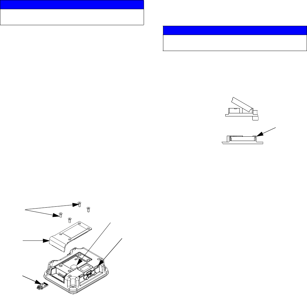
Replace Display Battery
1. Perform steps 1-2 in the Upgrade Software section
on page 13.
2. Use a flat head screwdriver to pry out old battery.
3. Replace with new battery. Ensure battery fits under
connector tabs before snapping other end in place.
NOTE:
Use only Panasonic CR2032 batteries for replacement.
4. Use screws (512) to install access cover (511).
NOTICE
To avoid damaging circuit board, wear a grounding
strap.
L
T
512
511
Battery
r_xm1a00_312359_313289_2a
NOTICE
To avoid damaging circuit board, wear a grounding
strap.
Connector
Tabs
Remove Old Battery
Insert New Battery
r_xm1a00_312359_313289_9_8a
Repair
14 3A2989G
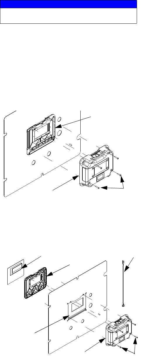
Replace Display
NOTE: Order display kit 257484 for replacement.
1. Remove Control Box Shrouds, see page 17.
2. Disconnect CAN cable from display module.
3. Remove four screws (505) from rear display panel
(506) while holding front display panel (507) in
place.
NOTE:
To ease removal use clear tape to hold front display
panel (507) in place.
4. Remove rear display panel (505) and disconnect
display cable and key switch cable (539) from circuit
board.
5. Remove front display panel (507) and gasket (513).
6. Discard old display assembly.
7. Place new front display panel (507) and
gasket (513) on front panel of control box (16).
NOTE:
To ease installation use clear tape to hold front display
panel in place.
8. Carefully connect display cables and key switch
cable to new circuit board.
9. Install new rear display panel (506) and secure with
four screws (505). Ensure key switch cable pro-
trudes from opening in top of display module.
10. Install access cover and screws. Apply warning
label to access cover.
11. Reconnect CAN cable to display module.
12. Reconnect power.
13. Load software. See Upgrade Software, page 13.
14. Replace shroud.
15. Configure system settings as they were set on old
display. See XM PFP Operation manual for instruc-
tions.
Replace Front Panel
See Replace Display, page 14, for instructions.
NOTICE
To avoid damaging circuit board, wear a grounding
strap.
r_312359_313289_24a
505
507
506
r_xm1a00_312359_313289_25a
505
506
513
507
Display Cable 539
Repair
3A2989G 15
Junction Box
Update High Power Temperature Control
Module (HPTCM, ref. 404) Software
NOTE: Upgrade all modules in the system to the
software version on the token, even if you are
replacing only one or two modules. Different soft-
ware versions may not be compatible.
All data in the module may be reset to factory
default settings. Record all settings and user prefer-
ences before the upgrade, for ease of restoring
them following the upgrade.
The latest software version for each system can be
found at Tech Support at www.graco.com.
1. Open junction box.
2. Use software token 16P644. See Graco Control
Architecture
™
Module Programming manual for
instructions.
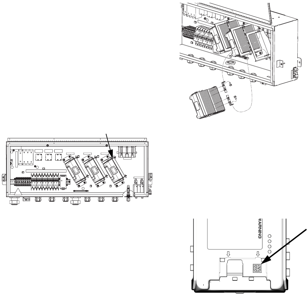
Replace High Power Temperature Control
Module (HPTCM, ref. 404)
1. Turn system main power switch OFF.
2. Open junction box.
3. Unplug all connections on the HPTCM.
4. Remove screws securing HPTCM then remove
HPTCM.
5. Remove access door on new HPTCM. Set rotary
switches to the same number as the old module.
B module = 1. Hose module = 2. A module = 0.
6. Use screws to install HPTCM.
7. Reattach HPTCM connections.
8. Close junction box.
B HOSE A
404
ti20155a
ti21595a
ti12360a
Repair
16 3A2989G
Update Fluid Control Module Cube (FCM3,
ref. 415) Software
NOTE: Upgrade all modules in the system to the
software version on the token, even if you are
replacing only one or two modules. Different soft-
ware versions may not be compatible.
All data in the module may be reset to factory
default settings. Record all settings and user prefer-
ences before the upgrade, for ease of restoring
them following the upgrade.
The latest software version for each system can be
found at Tech Support at www.graco.com.
1. Open junction box.
2. Use software token 16P644. See Graco Control
Architecture
™
Module Programming manual for
instructions.
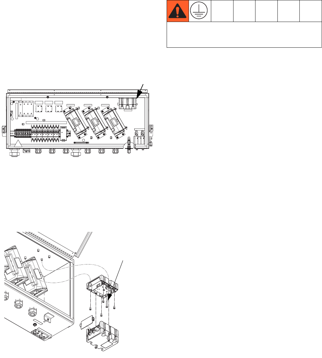
Replace Fluid Control Module Cube (FCM3,
ref. 415)
1. Turn system main power switch OFF.
2. Open junction box.
3. Unplug all connections on the FCM3.
4. Remove two screws securing FCM3 then remove
FCM3.
5. Use screws to install FCM3.
6. Reattach FCM3 connections.
7. Perform Update Fluid Control Module Cube
(FCM3, ref. 415) Software on page 16.
8. Close junction box.
B HOSE A
415
ti20155a
ti21594a
Ground screw
Center ground screw in the Fluid Control Module
Cube must be used to avoid serious injury due to
electric shock.
Repair
3A2989G 17
Air Controls
Remove Control Box Shrouds
1. Close main air shutoff valve on air supply line and
on system. Depressurize air line.
2. Remove four nuts (21) and then remove front and
rear shrouds (19, 20).
Remove Air Control Assembly
1. Remove Control Box Shrouds.
2. Disconnect air motor air lines and system air line.
3. Remove four nuts (17) from front of air controls (18).
See page 36.
4. Pull out assembly.
5. Follow steps in reverse order to reinstall air control
assembly.
Replace Solvent Pump Air Ball Valve
1. Remove Control Box Shrouds.
2. Disconnect air motor air lines and system air line.
3. Remove four nuts (17) from front of air controls (18).
See page 36.
4. Pull out assembly.
5. Remove two nuts (630) from front of air control
bracket (619). See F
IG
. 5 on page 18.
6. Disconnect air line (632) running to ball valve
assembly (626).
7. Replace with new ball valve assembly. See part
number shown in the System Air Controls Module
(255761) section beginning on page 44.
8. Follow steps in reverse order to reassemble.
Replace Solvent Air Regulator
1. Remove Control Box Shrouds.
2. Disconnect air motor air lines and system air line.
3. Remove four nuts (17) from front of air controls (18).
See page 36.
4. Pull out assembly.
5. Remove regulator nut (631), and disconnect air
lines (632, 633) running to regulator (625). See F
IG
.
5 on page 18.
6. Remove regulator assembly and replace with new.
See part number shown in the System Air Con-
trols Module (255761) section beginning on
page 44.
7. Follow steps in reverse order to reassemble.
Replace System Air Regulator
1. Remove Control Box Shrouds.
2. Disconnect air motor air lines and system air line.
3. Remove four nuts (17) from front of air controls (18).
See page 36.
4. Pull out assembly.
5. Remove regulator nut (601h) and disconnect sys-
tem air line.
6. Remove screws from quick clamps and open
clamps (601f) at hinge.
7. Remove regulator assembly (601c) and replace with
new. See part number shown in the System Air
Controls Module (255761) section beginning on
page 44.
8. Follow steps in reverse order to reassemble.
Replace Solenoid Inlet Air Regulator
1. Remove Control Box Shrouds.
2. Disconnect air motor air lines and system air line.
3. Remove four nuts (17) from front of air controls (18).
See page 36.
4. Pull out assembly.
21
20
19
ti19926a1
Repair
18 3A2989G
5. Disconnect air line.
6. Remove gauge (606) from block (601e).
7. Remove screws from quick clamps (601f) holding
air regulator assembly (601c) in place.
8. Open clamps (601f) at hinge and pull apart from
block (601e).
9. Remove regulator assembly (601d) and replace
with new. See part number shown in the System
Air Controls Module (255761) section beginning
on page 44.
10. Follow steps in reverse order to reassemble.
11. Set new air pressure regulator to at least 80-85 psi
(0.55-0.58 MPa, 5.5-5.8 bar).
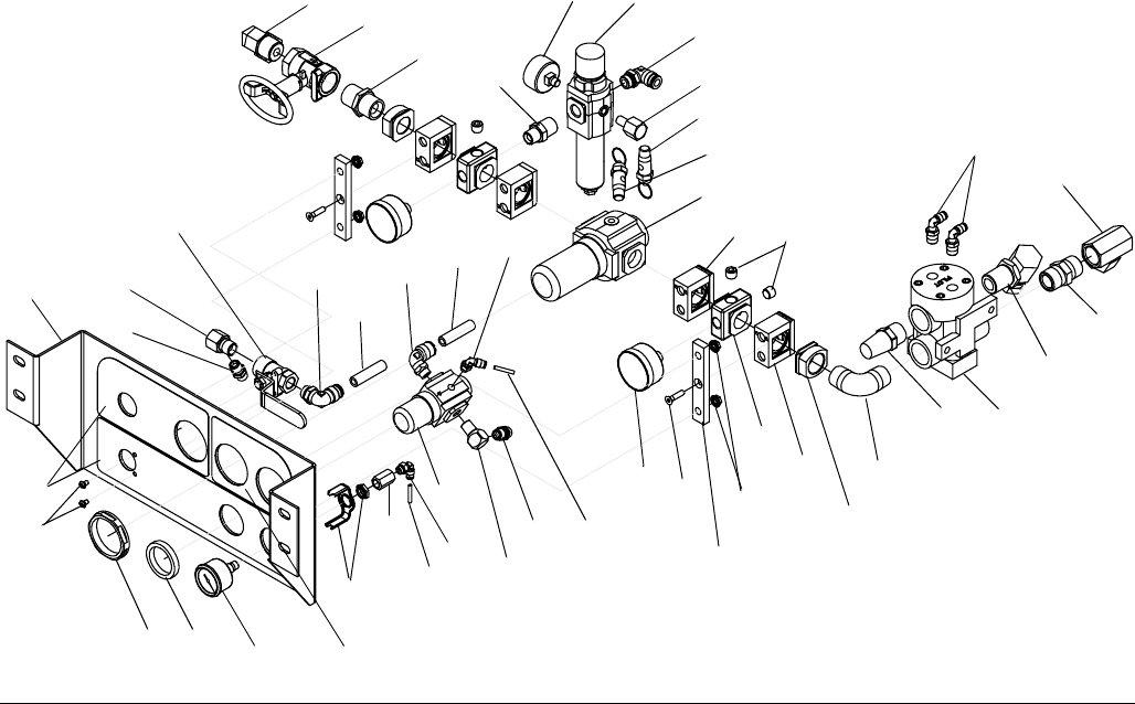
F
IG
. 5
604
640 631
633
611
617
615
613
606
618
603
609
629
625
620
621 622
617
612
616
610
607 608
635
633 634
635
629
627
628
627
632
636
626
638
632
637
619
618
630 641
646
644
645
642
642
643
647
613
Ref. 27
Repair
3A2989G 19
Dosing Valve Assembly
1. Follow Pressure Relief Procedure, page 7.
2. Disconnect all fluid lines from dosing valves (28 or
29). See F
IG
. 6.
3. Remove two bolts (31) securing dosing valve to
bracket.
4. Unscrew dosing valve nipple fitting (36 or 37) from
dosing valve outlet.
5. Disconnect pressure sensor (831) from dosing
valve. See page 50.
6. Remove dosing valves.
7. See Ratio Control Valve Assemblies on page 50
for disassembly illustration.
8. Follow steps in reverse order to reassemble dosing
valve assembly. See Ratio Control Valve Assem-
blies on page 50 for assembly illustration and spec-
ifications.
F
IG
. 6
29
28
55
55 54
85
31
37
36

Repair
20 3A2989G
Sensors
Replace Fluid Pressure Sensor
1. Close main air shutoff valve on air supply line and
on system.
2. Follow Pressure Relief Procedure, page 7.
3. Open control box cover. See User Interface/Con-
trol Box, page 10.
4. Disconnect pressure sensor (831) from dosing
valve. See Ratio Control Valve Assemblies on
page 50.
5. Disconnect other end of pressure sensor (831) from
FCM (518). See Control Box (255771) on page 47.
6. Replace with new fluid pressure sensor, and recon-
nect pressure sensor to FCM and dosing valve.
Hose Bundle Temperature Sensor (93)
1. Disconnect the M8 cable connection going into the
hose bundle.
2. Open up the hose bundle wrap and insulation until
sensor (93) can be removed easily without pulling
on cable.
3. Remove sensor.
4. Push new sensor fully into insulated portion of hose
bundle.
5. Close insulation and hose bundle wrap and re-tape.
Ensure there is no stress on the cable.
6. Reconnect M8 connector.
Replace Temperature (RTD) Sensors
This procedure applies to:
• Tank sensors mounted in the side of each tank near
the bottom (209).
• Glycol heater for hose outlet manifold sensor (100).
1. Close main air shutoff valve on air supply line and
on system.
2. Follow Pressure Relief Procedure, page 7.
3. Disconnect the M8 cable connection.
4. Loosen the compression nut. Pull sensor straight
out of fitting.
5. Remove fitting (82 or 208).
NOTE: The compressed ferrule cannot be removed
from the sensor. A new compression fitting must be
used.
6. Apply thread sealant then replace compression
fitting (82 or 208). Tighten fitting in place.
7. Position sensor (100 or 209):
•Tank: Insert sensor, leaving 5/8 in. sheath out-
side fitting.
•Heater manifold: Insert sensor, leaving 1/8 in.
sheath outside fitting.
8. Install compression nut on sheath hand-tight then
tighten an additional 3/4 turn.
Repair
3A2989G 21
Pump Assembly (System
Module)
Prior to servicing the pump assembly you must first
remove either the entire pump assembly or the displace-
ment pump and air motor individually.
Remove Pump Assembly
1. Follow Pressure Relief Procedure, page 7.
2. Close ball valve at metering pump inlet.
3. Disconnect fluid inlet line from the displacement
pump. Leave line connected to the tank.
4. Disconnect air motor.
a. Disconnect sensor cable, air line, and ground
wire from air motor.
b. Remove mounting screws (5) and washers (4)
holding air motor (2 or 3) to mounting bracket.
See F
IG
. 7 on page 22.
5. Use lift ring on air motor to remove pump assembly.
6. Refer to Xtreme Displacement Pump manual
311762 to service or repair the displacement pump.
Refer to NXT Air Motor manual 311238 to service or
repair the air motor.
7. Follow steps in reverse order to reinstall pump
assembly.
Remove Displacement Pump
Follow these instructions for removing only the displace-
ment pump; the air motor will remain installed.
1. Follow Pressure Relief Procedure, page 7.
2. Close ball valve on tank outlet.
3. Disconnect fluid inlet line from the displacement
pump. Leave line connected to the tank.
4. Remove clip (2b), and slide coupling cover (2c) up
to remove coupling (2a).
5. Use a wrench to hold the tie rod flats to keep the
rods from turning. Unscrew the nuts (2e) from the tie
rods (2d) and carefully remove the displacement
pump (2f).
6. Refer to the Xtreme Displacement Pump manual
311762 to service or repair the displacement pump.
7. Follow steps in reverse order to reinstall displace-
ment pump.
To avoid serious injury from falling objects caused by
the lift ring breaking, do not lift pump assembly by the
lift ring when the total weight of the pump assembly
exceeds 550 lb (250 kg).
ti8264a
2a
2c
2b
ti8301a
2d
2e
2f
Repair
22 3A2989G
Remove Air Motor
1. Follow Pressure Relief Procedure, page 7.
2. Disconnect displacement pump from air motor. See
steps 2 and 3 under Remove Displacement Pump,
page 21.
3. Disconnect sensor cable, air line, and ground wire
from air motor.
4. Remove mounting screws (5) and washers (4) hold-
ing air motor (2 or 3) to mounting bracket.
5. Refer to NXT Air Motor manual 311238 to service or
repair the air motor.
6. Follow steps in reverse order to reinstall air motor.
Pail Feed RAM Pump Assembly
(Feed Module)
NOTE: See Pail Feed RAM Pump assembly (227) in
parts breakdown beginning on page 40.
See Supply Systems manual 313527 for service and
repair instructions and parts.
Solvent Pump
1. Follow Pressure Relief Procedure, page 7.
2. Disconnect pump inlet line (154) and air lines (57,
60) from solvent pump.
3. Disconnect fluid outlet line.
4. Remove four screws (153) that attach solvent
pump (8) to bracket (152) and remove solvent
pump.
5. Refer to Merkur Pump Assembly manual 312794 to
service or repair solvent pump 257463.
6. Follow steps in reverse order to reinstall solvent
pump.
F
IG
. 7
2 or 3
5
4
Bracket
r__312359_313289_32
57
153
8
60
154
152
Repair
3A2989G 23
Heaters
NOTE:
See applicable heater manual for wiring, repair, and
parts information. See Related Manuals on page 3.
Service and Repair
1. Follow Pressure Relief Procedure, page 7.
2. Disconnect fluid lines and electrical wiring from fluid
heater.
3. Refer to heater manual to service or repair heater.
4. Reconnect fluid lines and electrical wiring.
Replace
1. Follow Pressure Relief Procedure, page 7.
2. Disconnect fluid lines and electrical wiring from fluid
heater.
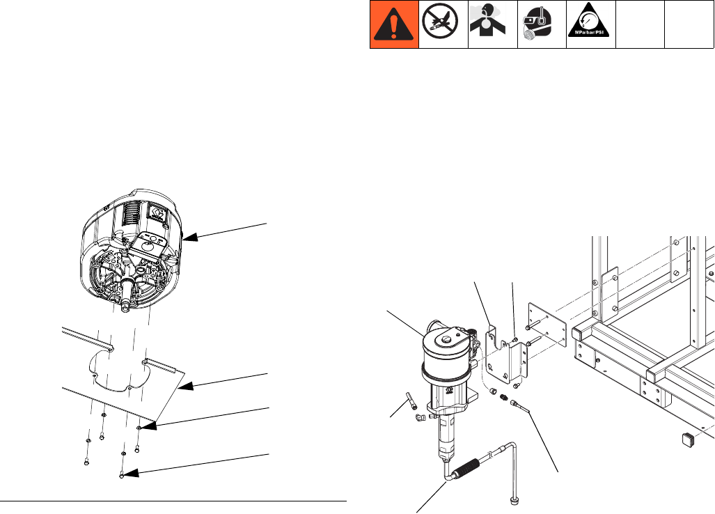
3. System Module Heaters: See F
IG
. 8. Loosen four
mounting screws, lock washers, and plain washers
on back of heater (12 or 13) that secure it to the sys-
tem frame. Slide heater up and remove from mount-
ing plate.
4. Feed Module Heaters: See page 41. Remove 2
screws (224) then remove heater (226) from feed
module frame.
5. Replace heater. Follow steps in reverse order to
install new heater.
F
IG
. 8: Heaters on System Module
12
13
12
Repair
24 3A2989G
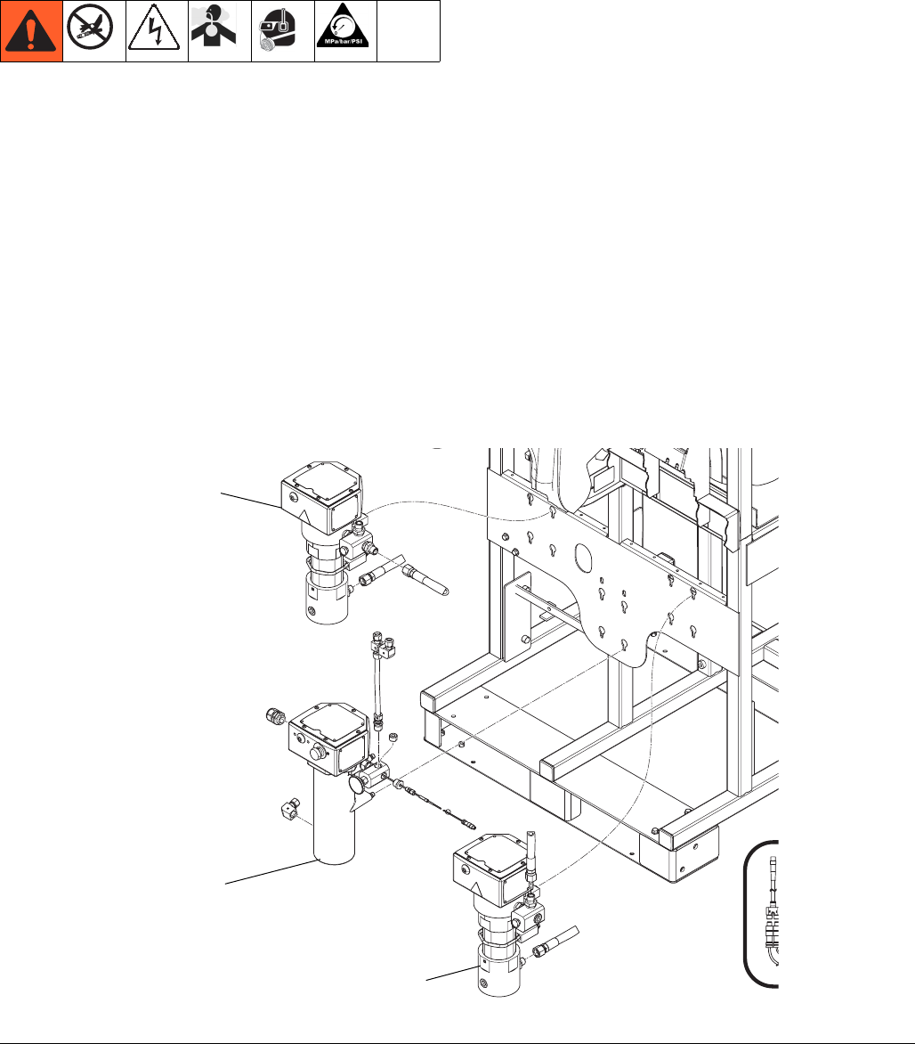
Replace Radar Level Sensor
NOTE: Order radar level sensor kit 24T052. See Feed
Module (24P883) on page 40 for kit contents.
NOTE: Tank level sensors changed in 2014. The old
sensors were red. The new sensors are blue. The blue
sensors can be used as direct replacements for the red
sensors.
1. With the tank empty, close the tank air supply ball
valve then open brass valve on tank lid to de-pres-
surize the tank. See F
IG
. 9.
2. Disconnect cable at the bottom of the feed module.
NOTE: Always use the new cable supplied with the
sensor. It has different connections than the old
sensor.
3. Disconnect 3/4 in. union that holds the level sensor
on top of the tank.
4. Pull the old sensor straight up out of the tank.
5. Remove plugs from new sensor and discard plugs.
Move fittings from old sensor to new sensor.
6. If the sensor rod was removed for shipping, apply
blue thread-lock to the threads in the end of the rod.
7. Feed the rod into the sensor head and screw the
threaded end into the sensor head.
8. Use a wrench to hold the 3/8 in. flats on the sensor
rod.
9. Tighten to approximately 25 - 30 in-lb (2.8 - 3.4
N•m). Do not over-tighten.
10. Reconnect sensor cable.
11. See Set Up a New Guided Level Sensor, page 25.
F
IG
. 9: Level Sensor Installation
WLD
Tank Air
Supply Ball
Valve location
(on other side
of panel)
Valve
Repair
3A2989G 25
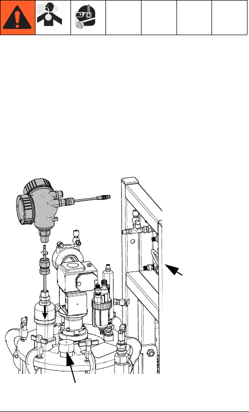
Set Up a New Guided Radar Level Sensor
Level sensors need to have three settings setup after installing on the tank of the PFP machine. The tank must be
empty, or the level needs to be at least below the bottom of the installed probe with the tank cover closed.
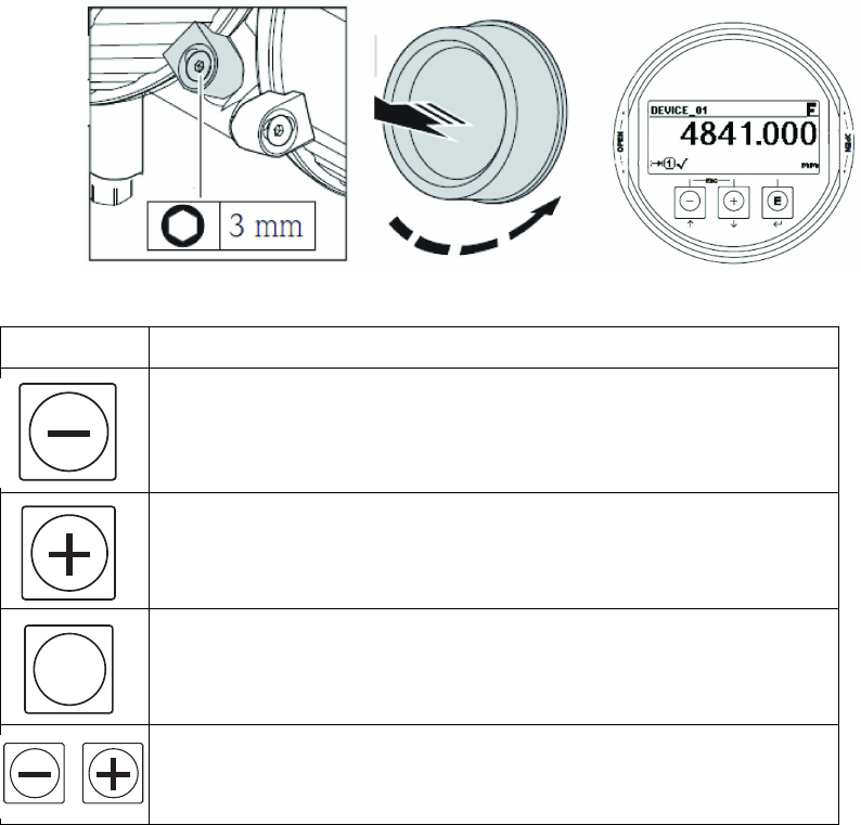
1. Open the sensor head cover over the display:
a. Loosen the securing clamp with an Allen wrench (if clamp is present).
b. Unscrew the round cover and pull away.
Use the operating keys to navigate within the operating menu and to select options from a list.
2. Turn power on the machine. Set EMPTY CAL, then FULL CAL, then do a mapping of the Empty Tank.
3. Set EMPTY CAL to .939 meters:
a. Press E, then +, +, to get to Set Up. Then press E to get to EMPTY CAL, then press E.
b. Press + until decimal point (.) appears, then press E.
c. Press + until 9 appears, then press E.
d. Press + until 3 appears, then press E.
e. Press + until 9 appears, then press E.
f. Press and hold E until the hourglass appears, then release.
Key Meaning
“Minus” Key
• In a selection list, this key will move the selection bar upward.
• In an input matrix, this key will move the selection bar backward.
“Plus” Key
• In a selection list, this key will move the selection bar downward.
• In an input matrix, this key will move the selection bar forward.
“Enter” Key
• Opens the marked sub-menu or parameter.
• Confirms a changed parameter value.
“Escape” Key combination (press keys simultaneously)
• Closes a parameter without accepting the changes.
• Quits the current menu layer and returns to the next higher layer.
ti24380a
E
+
Repair
26 3A2989G
4. Set FULL CAL to .691 meters.
a. Press + to get to FULL CAL, then press E.
b. Press + until decimal point (.) appears, then press E.
c. Press + until 6 appears, then press E.
d. Press + until 9 appears, then press E.
e. Press + until 1 appears, then press E.
f. Press and hold E until the hourglass appears, then release.
5. Map EMPTY TANK.
a. Press + to get to MAPPING, then press E.
b. Press E to get to CONFIRM DISTANCE.
c. Press + until TANK EMPTY appears, then press E.
d. Press + under the check mark to confirm, END OF SEQUENCE will appear. Press and hold E until the hour-
glass appears, then release.
e. You are now finished. Press + and - together until the hourglass appears, then release.
6. The transmitter display should show nothing in the tank. Check the level display on the PFP machine control. It
should also show the tank as empty.
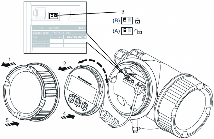
7. These settings can now be locked from display control so they will not be inadvertently changed.
8. Set display to lock ON:
a. Turn display counter-clockwise to release it as shown below (2).
b. Set the dip switch to the lock position as shown below (3).
c. Replace display (4).
d. Replace screw on lid (5).
e. Engage cover securing clamp.
Electrical Schematics
3A2989G 27
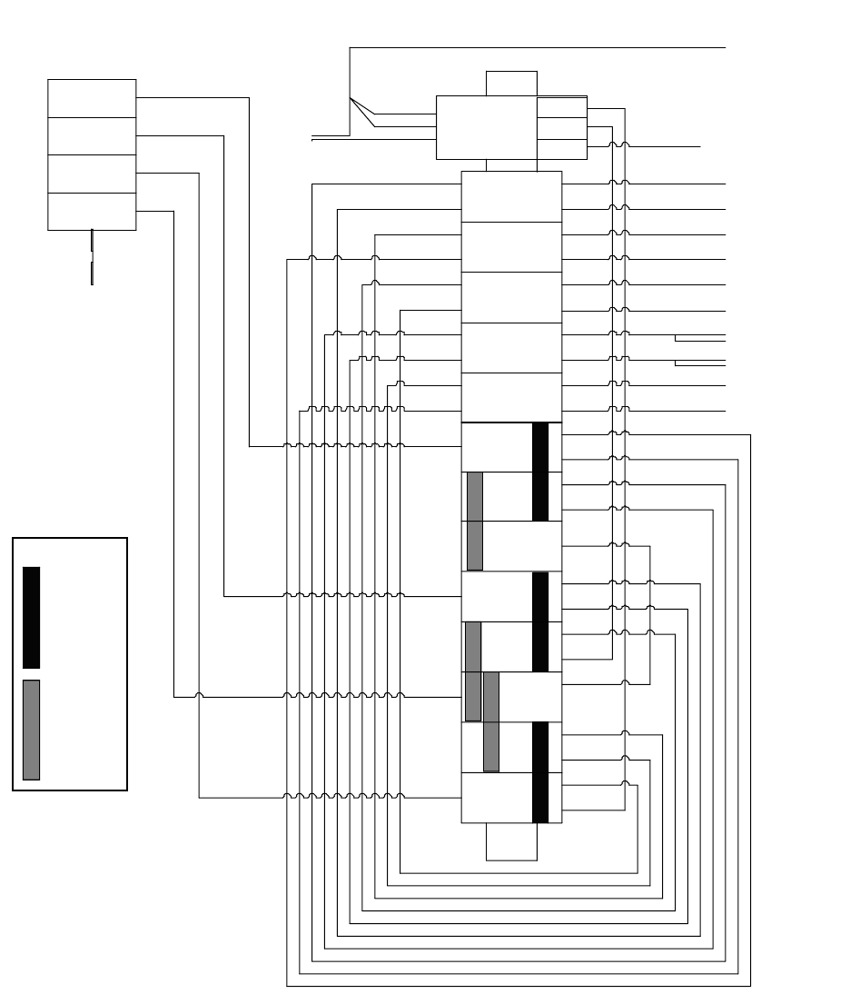
Electrical Schematics
Simplified Electrical Schematic
Page 1 of 3
TB1
TB3
TB8
TB6
1
CB2
20A
126128
1
CB3
30A
126130
1
CB4
20A
126128
1
CB5
30A
126130
1
CB1
25A
126129
CB5-3
CB5-1
CB1-3
CB1-1
CB3-1
CB3-3
CB4-1
CB4-3
CB2-3
CB2-1
TB8-2
TB8-2
TB7-2
TB7-2
TB2-2
TB5-2
TB2-2
TB8-1
TB5-1
TB3-1
TB1-1
TB1-2
TB5-2
TB4-2
TB6-2
CB5-4
CB5-2
CB2-4
CB2-2
TB4-2
TB1-2
CB3-2
CB3-4
CB4-2
CB4-4
TB2
TB5
TB7
CB1-2
CB1-4
TB4
3
3
3
3
3
GND-2
24VDC
Power Supply
+L
GND
N
GND-3
N
L
+
-
-
230VAC
KEY:
DELTA
JUMPER
POSITIONS
N
L3
L2
L1
DISC1
Switch - 123969
4th
pole - 123968
FIELD
WIRE
SIDE
GRACO
WIRE
SIDE
RED +V
BLACK -V
TB3-2
16T147
PS1
380VAC
WYE
JUMPER
POSITIONS
2
4
2
4
2
4
2
4
2
4
TCMA-5L2
TCMA-5L1
SW3-3
SW1-1
TCMB-5L1
TCMB-5L2
TCMH5L1
TCMH-5L2
SW2-1
SW2-3
SW1-3
SW3-1
24VDC
POWER
Din rail
Electrical Schematics
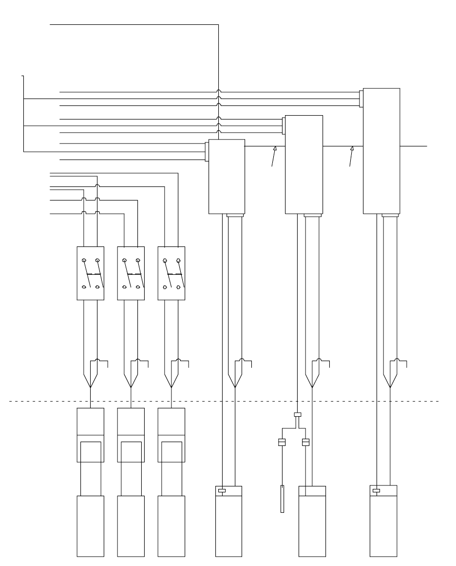
28 3A2989G
Page 2 of 3
HOSE HEATER
4KW
245869
262853
16T525
16T525
16T859
AFLUID HEATER
5.4KW
NEMA
L6-20R
3
1
2
4
3
1
2
4
GND-2 GND-2 GND-2
BT
ANK HEATER
1.75KW
FLUSHHEATER
5K W
AT
ANKHEATER
1.75KW
NEMA
L6-30R
NEMA
L6-20R
NEMA
L6-20P
NEMA
L6-30P
NEMA
L6-20P
BLA CK
BLA CK
WHITE
WHITE
BFLUID HEATER
5.4KW
24P242
SW2-
1
SW2-
3
SW3-
1
SW3-
3
SW1-
3
SW1-
1
TC
MB-6
TCMB-6
TCMA-6
TCMB-5L2
GND-2
TCMB-5L1
SW1-
2
SW1-
4
SW2 -
2
SW3-
2
SW3-
4
SW2-
43
1
2
4
TCMB
255774
126511
126511
566
3
2
TCMB-
3L1
TCMB-
3L2
26
TCMH
255774
66
32
TCMH-
3L1
TCMH-
3L2
5
TCMH-5L2
GND-2
TCMH-5L1
TCMA
255774
66
32
TC
MA-3L1
TCMA-3L2
5
TCMA-5L2
GND-2
TCMA-5L1
TCMH-6
24VDC
POWER
TCMH-6 CAN
TCMA-6
TCMA-5L2
GND-2
TCMA-5L1
SW3-3
SW1-1
TCMB-5L1
TCMB-5L2
TCMH5L1
TCMH-5L2
SW2-1
SW2-3
SW1-3
SW3-1
16T147
Cable
125789
Cable
125789
SW1
Switch -15U423
15U423
15U423
SW2
Switch -
SW3
Sw
itch -
BLA CK
WH ITE
GND-2
BLACK
WHITE
GND-2
BLACK
WHITE
GND-2
BLACK
WHITE
Power
Distribution
Enclosure
125357
126427
262853
12
Splitter
125806
Electrical Schematics
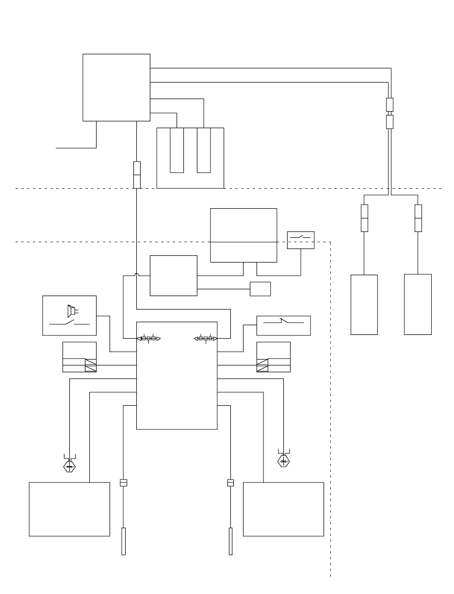
3A2989G 29
Page 3 of 3
126495
124273
126494
126494
127172
24T052
24T052
127172
121806
121806
ALEVE LSENSOR
16T123
FCM1
Base - 289697
FCM - 2896961
5
7
2
BLEV
ELSENSOR
FCM1
126496
16T072
FCM1
CAN
USB1
Base - 289899
USB - 289900
DISPLAY SHIELD
15M483
DISPLAY
FRONT 255727
Air Motor Junction Box
NXT411
Linear Sensor - 256893
Reed Switch
ATankRTD
BT
ankRTD
Air Motor Junction Box
NXT411
Linear Sensor - 256893
Reed Switch
15M669
15M669
Dose A
Motor A
Dose B
Motor B
Stop - 121619
Power
Distribution
Enclosure
Control Enclosure
Manifold
Soleno id A
Soleno id B
15V779
Buzzer - 122000
Start - 121618
Manifold
256555
Manifold
256555
15M977 15M977
15U542 15U542
2
1
5
4
33
1
2
4
5
A BLUE B
GREEN
AFCM
255920
15M975 15M976
15M974
SETUP
KEY 121617
DISPLAY LCD
288997
121683
121683
15V778
USB
15R324
126381
126381
Electrical Schematics
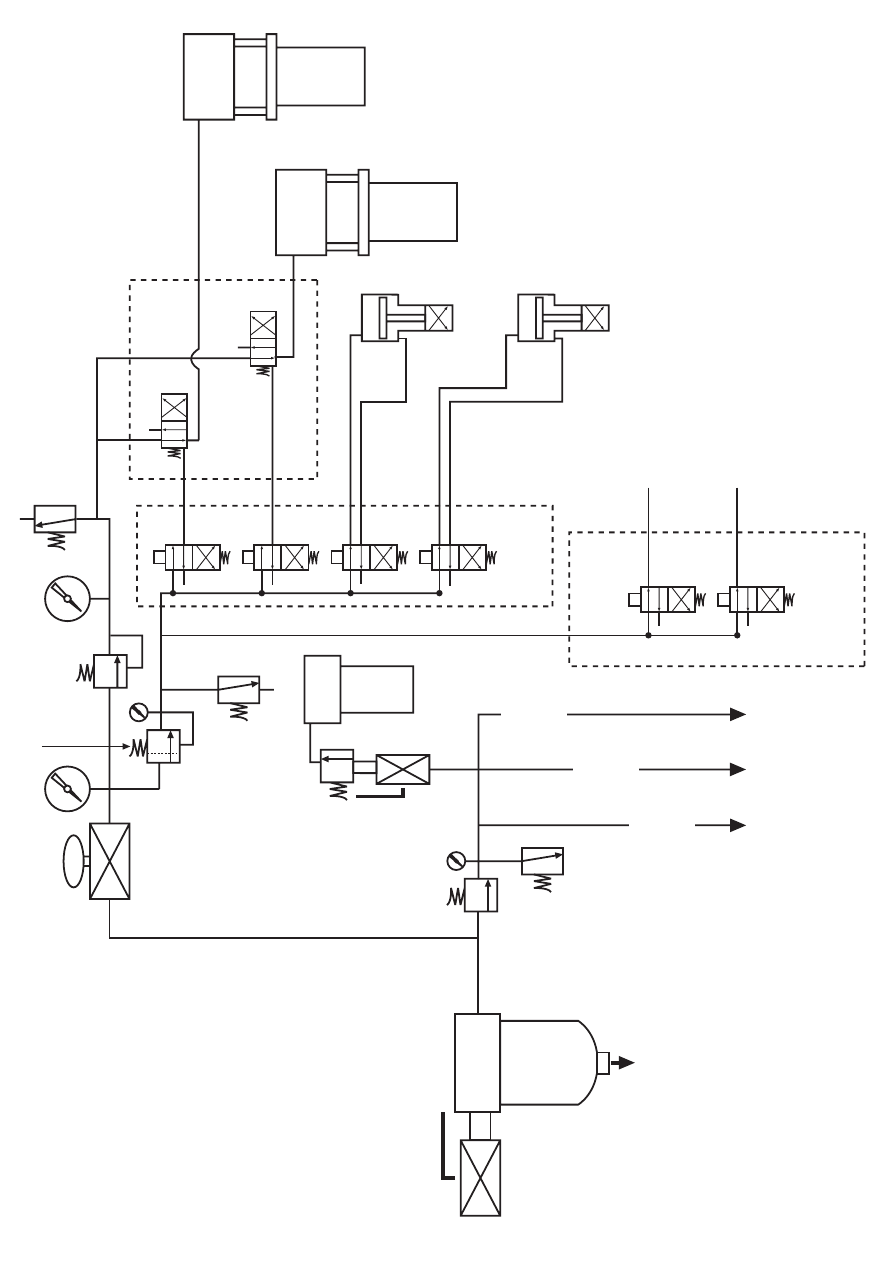
30 3A2989G
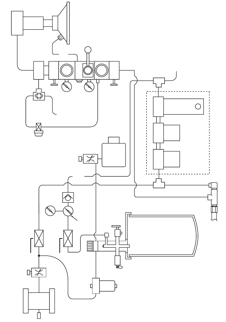
XM PFP Air Logic Schematic
1” {ರ
PLFURQ
$872
-XQFWLRQ
%R[
6ROHQRLGV
;0&RQWURO
%R[
6ROHQRLGV
7R3QHXPDWLF
5DPSXPSSLORW$
7R3QHXPDWLF
5DPSXPSSLORW%
'RVLQJ
9DOYHV
;0'XDO
SLORW
YDOYH
3803
$
3803
%
+LJK3UHVVXUH
0HWHULQJ3XPSV
SVLOLPLW
(;+
3XPS
5HJ
0LFURQ
)LOWHU5HJ
0DLQ
FRQWURO
YDOYH
SVL
OLPLW
(;+
)OXVK
3XPS
SVL
OLPLW
7R
$
)HHG
0RGXOH
7R
%
)HHG
0RGXOH
7R
+RVH
&LUF
3XPS
6\VWHP
9DOYH
Electrical Schematics
3A2989G 31
Feed Module Air Controls Schematic
3XPS
3LORW
:DWHU
3XPS
7DQN
+HDW
6SHHG
&RQWURO
~
7XEH
212))
&LUF$JLWDWRU
~ 5HGKRVH
212))
7DQN
3UHVVXUH
5HG
KRVH
~
~ 5HGKRVH
9HQW
3UHV
5HOLHI
9DOYH
7DQN/LG
0DQLIROG
$JLWDWRU
0RWRU
/XEULFDWRU
$LU)URP
3URSRUWLRQHU
ೀ5HGKRVH
~ 5HGKRVH
5HGKRVH
2SWLRQDO
7DQN
'U\$LU
'U\$LU
WRWDQN
LINLWLVXVHG
$LU
0RWRU
$JLWDWRU
6SHHG
&RQWURO
5HGKRVH
%ODFN
From
J-Box
Level
Solenoid
%ODFN 3XPS
2))21
5DP
2))21
)HHG
3XPS
3DLO
3DLO
%ORZRII
~
:KLWH
83
5$0
'2:1
35(6685(
5(*8/$725
%ODFN 5DP
3XPS
5HJ
3XPS
2YHULGH
3XVK
%XWWRQ
Parts
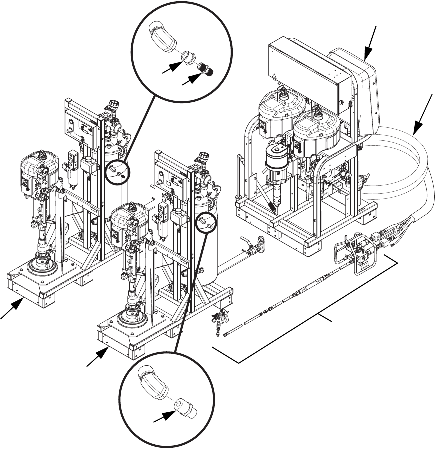
32 3A2989G
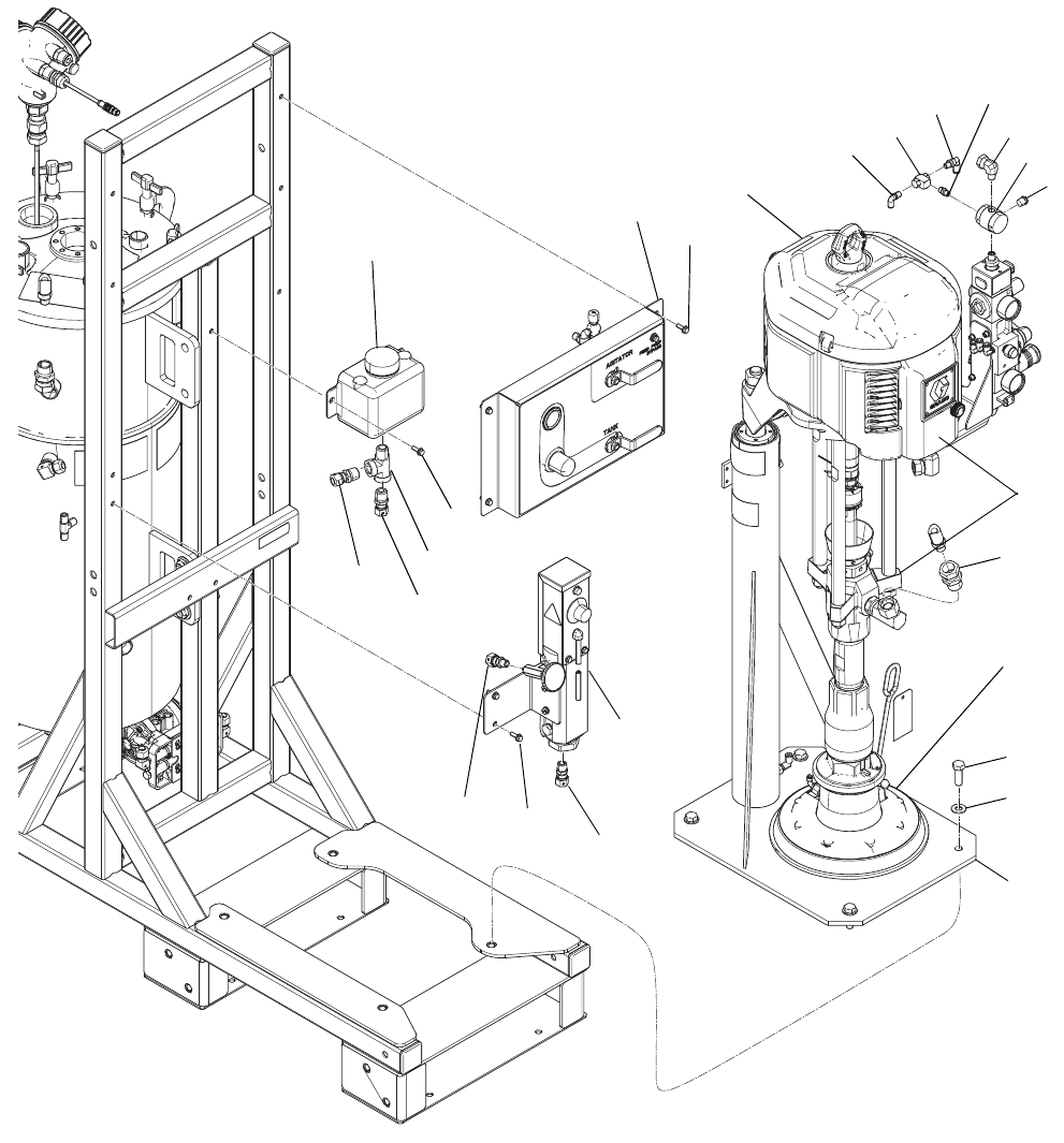
Parts
XM PFP System (262869, 24W626)
--- Not for sale.
◆Not shown.
‡ Not required for model 24W626.
* Qty. 2 required for 24W626.
Ref. Part Description Qty.
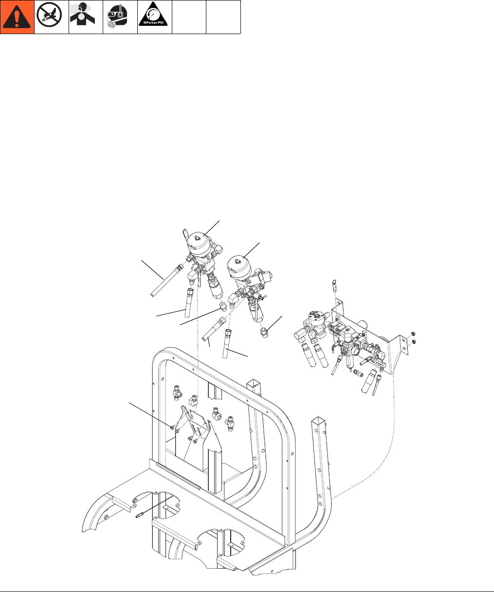
1 SYSTEM MODULE AND MIX LINE 1
262878 Model 262869
24W648 Model 24W626
2 FEED MODULES ASSEMBLY 1
24P202 Model 262869
24W628 Model 24W626
2a 24P883 FEED MODULE 2
2b* C20461 NIPPLE, reducing 1
2c‡ 100505 BUSHING 1
2d‡ 156849 NIPPLE 1
2f◆15U654 LABEL, A/B Identification 1
2g◆061134 HOSE, nylon 2.5
2h◆--- CABLE TIE 8
3 HEATED HOSE BUNDLE 1
16T121 Model 262869
16T122 Model 24W626
Ref. Part Description Qty.
‡
2c
2a
2a
‡
2d
*2b
3
1
ti20491a
1
Parts
3A2989G 33
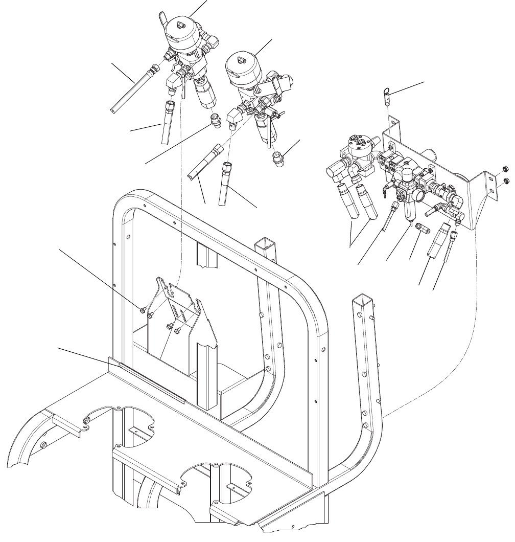
XM PFP System (262869, 24W626) Subassemblies
Base System (262878, 24W648)
Page 1 of 5
46 85 95 96 61 97 99
61
NOTE: Apply pipe sealant to all non-swiveling pipe threads.
Heated Hose Bundle 16T121. Not included with assemblies 262878 and 262869.
Shown for reference only.
Heated Hose Bundle 16T122 not included with assembly 24W648 and 24W626.
Shown for reference only.
98
ti20154a
Parts
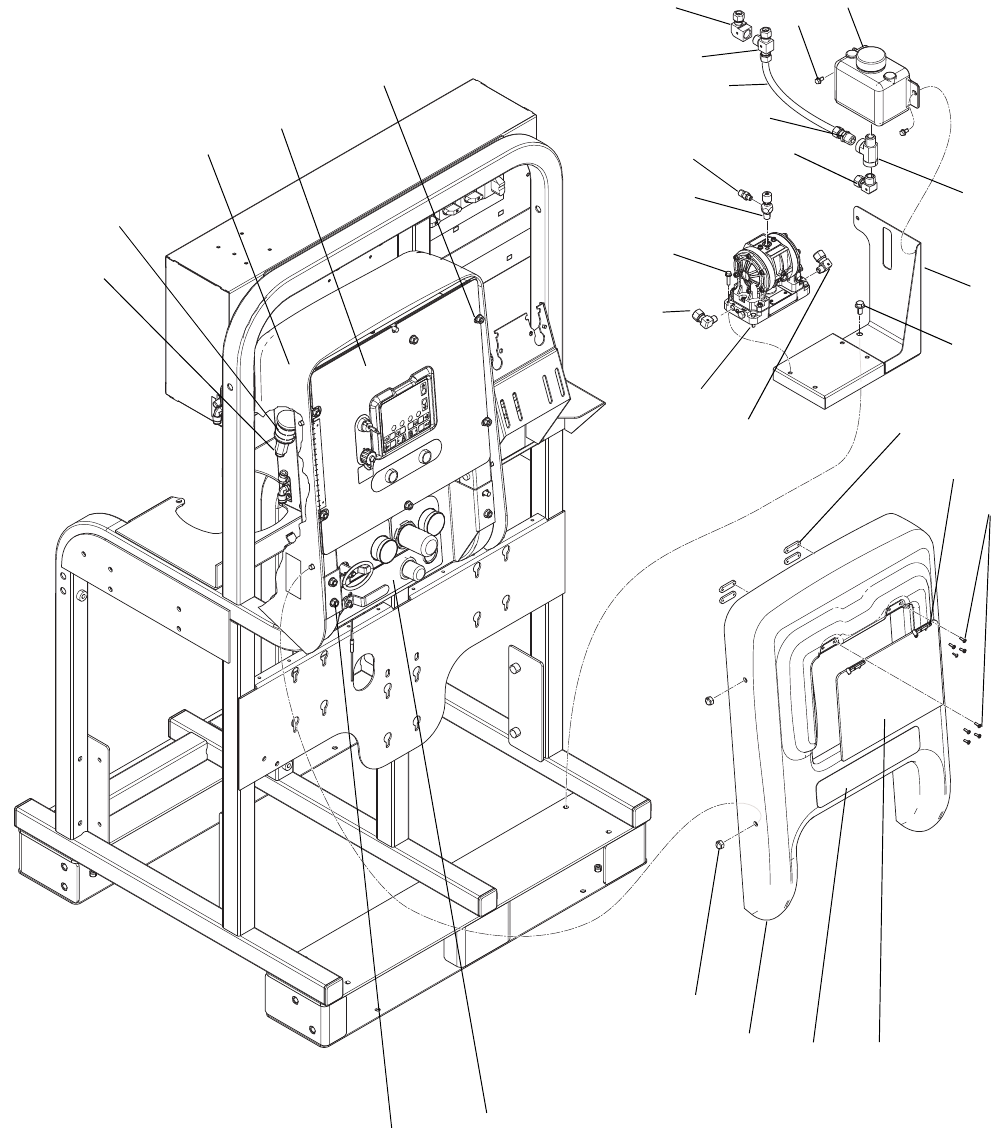
34 3A2989G
Base System (262878, 24W648) page 2 of 5
10
11
45, 11
140
4, 5
43
140
43
36
44
1
41
57
151
8
76
94
36
44
102
103
104
32
33
61
35
38
39
61
30
101
67
67
67
54
54
60
Set air regulator to 85 psi
(590 kPa, 5.9 bar)
3
2
140a
143
144
145
146
147
148
154
155
153
152
150
149
9
ti20156a
Parts
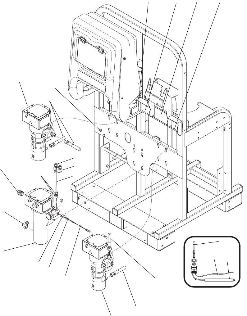
3A2989G 35
Base System (262878, 24W648) page 3 of 5
27
67
59
67
105
118
60
29
28
56
55 54
85
31
120
37
36
ti20157a
Parts
36 3A2989G
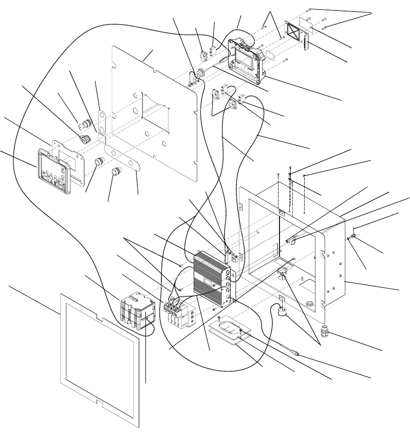
Base System (262878, 24W648) page 4 of 5
110
26
25
21
20 22 24
23
18
17
19
16
17
52
40
109
15
112
111
108
116
115
9
114
113
117
114
ti20158b
133
86
132
Parts
3A2989G 37
Base System (262878, 24W648) page 5 of 5
54
54
78 79
85
127 120
12
107
106
13
100
82
34
15
12
9
ti20159b
64
93 100
132
133
87
Parts
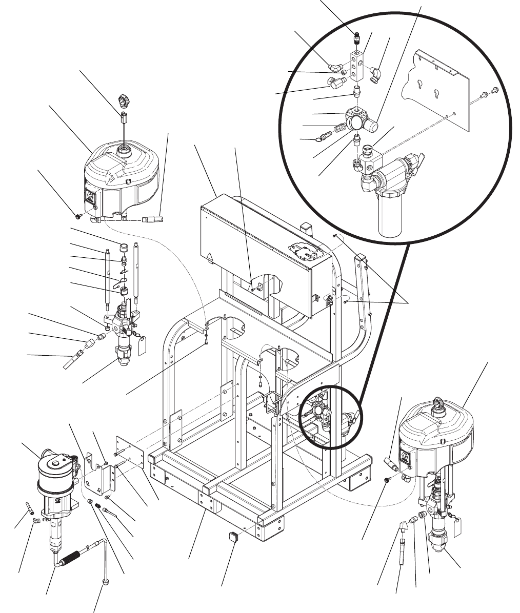
38 3A2989G
Base System (262878, 24W648)
Ref Part Description Qty
1 --- FRAME 1
2 L180C9 PUMP; B side lower 1
3 L220C9 PUMP; A side lower 1
4 100133 WASHER, lock, 3/8 8
5 100101 SCREW, cap, hex head 8
6 256169 PLATE, solvent pump 1
7 121488 SCREW, hex head, flanged 2
8 W30CAS PUMP, solvent, 6.0 in, 75 cc; see
312794
1
9 112395 SCREW, cap, flange head 8
10 24N598 JUNCTION BOX; see page 45 1
11 113796 SCREW, flanged, hex head 6
12 262853 HEATER, Viscon HF 2
13 245869 HEATER, Viscon HP 1
14 24P899 FILTER, air, 1-1/4, assembly 1
15 126899 FITTING, compression, straight 2
16 255771 BOX, control, air/electric 1
17 112958 NUT, hex, flanged 10
18 255761 MODULE, air controls, upper 1
19 --- COVER, shroud, rear 1
20 256177 COVER, shroud, front 1
21 117623 NUT, cap, 3/8-16 4
22 --- LABEL, XM PFP 1
23 15T567 NUT, backup plate, hinge 4
24 15T568 DOOR, control shroud 1
25 121471 HINGE, friction, positioning 2
26 112380 SCREW, mach, pan head 8
27 113498 VALVE, safety, 110 psi 1
28 --- VALVE, ratio control, left; see
page 50
1
29 --- VALVE, ratio control, right; see
page 50
1
30 C19024 FITTING, elbow, swivel 1
31 111801 SCREW, cap, hex head 8
32 217430 FITTING, swivel, union, 90 degree 1
33 15T536 REGULATOR, air, 3/8 npt 1
34 100329 BUSHING, pipe 1
35 116504 FITTING, tee, run 1
36 C20461 FITTING, nipple, reducing, hex
Model 262878 3
Model 24W648 2
37 160032 FITTING, nipple
Model 262878 2
Model 24W648 4
38 116643 VALVE, safety, relief, air 1
39 101689 GAUGE, press, air 1
40 121688 CONNECTOR, 3/8 npti x 3/8 tube
ptc
1
41 115313 PLUG, tube 8
42 160327 FITTING, union adapter, 90
degree
2
43 15J277 CONTROL, de-ice, assembly 2
44 15M987 FITTING, elbow, 60 degree 2
45 117666 TERMINAL, ground 1
46 262893 MANIFOLD, mix; see manual
3A2988
1
47 --- SEALANT, pipe, stainless steel 1
48 --- LUBRICANT, thread 1
49 --- SEALANT, anaerobic 1
50 206995 FLUID, TSL, 1 qt. 1
52 108636 MUFFLER 1
53▲15X393 LABEL, warning, USB, all
languages
1
54 H75003 HOSE, coupled, 7250 psi,
0.50 in. ID, 3 ft
3
55 H75004 HOSE, coupled, 7250 psi,
0.50 in. ID, 4 ft
Model 262878 3
Model 24W648 5
56 H73806 HOSE, coupled, 7250 psi,
0.375 in. ID, 6 ft
(Model 262878 only)
1
57 H42506 HOSE, coupled, 4500 psi,
0.25 in. ID, 6 ft
1
58 205418 HOSE, coupled, air, 1/2 x 6 ft 2
59 16P244 HOSE, coupled, air, 5/16 x 3 ft 2
60 248208 HOSE, coupled, air, 5/16 x 4 ft 1
61◆159239 FITTING, nipple, pipe, reducing 4
62 16A004 FLASH DRIVE, USB, 2.0 1
63 121456 CONNECTOR, power, male, 3 pin 1
64 125806 CABLE, splitter, M8, 4-pin,
female/female/male, 1.5 m
1
65 126511 CABLE, GCA, M8, 4-pin, 1.5 m,
male/female
2
66 16T123 CABLE, GCA, CAN, male/female,
1.0 m
1
67 240900 HOSE, coupled, air, 30 in. x 3/4 in. 3
68 054172 TUBE, nylon, round, black, 1/4 in. 26.5
69 054175 TUBE, nylon, round, natural,
1/4 in.
8.5
70 551390 SIGHTGLASS, beaker, graduated 10
71 --- STRAP, tie 20
73 238909 WIRE, grounding assembly 1
74 C12508 TUBING, nylon, round, black,
3/8 in.
4.7
76 109025 TERMINAL, ring 1
79 16P856 LABEL, codes, alerts; all
languages
1
80 125357 CABLE, M8, 4-pin, male/female,
1 meter
1
81 126494 CABLE, M12, 5p, 4-wire with drain 2
82 126351 FITTING, compression,
thermocouple
1
Ref Part Description Qty
Parts
3A2989G 39
--- Not for sale.
▲Replacement Danger and Warning labels, tags and
cards are available at no cost.
◆Included in mix line and gun kit 24P833.
85◆H75002 HOSE, coupled, 7250 psi, 0.5 in.
(12 mm) ID, 2 ft
2
86 --- TUBE, 0.375 in. (9.5mm) ID blue
nylon
6
87 --- TUBE, 0.375 in. (12 mm) ID red
nylon
1.5
88 114601 CONDUIT, flexible, non-metallic 3.5
92 15T258 TOOL, wrench, Xtreme, 145/290 1
93 24P242 SENSOR, RTD, 1k ohm, insulated 1
94 158586 FITTING, bushing 1
95◆16T316 MIXER, static, assembly 1
96◆H75010 HOSE, coupled, 7250 psi, 0.50 ID,
10 ft
1
97◆H73803 HOSE, coupled, 7250 psi, 0.375
ID, 3 ft
1
98◆24P834 SWIVEL, straight 1
99◆262854 GUN, spray 1
100 126427 SENSOR, RTD, 1K ohm, 4 pin,
8in.
1
101 158990 MANIFOLD, air 1
102 165198 FITTING, nipple, reducing 1
103 121858 FITTING, elbow, 3/8 npte x 1/4
npte
1
104 101754 PLUG, pipe 1
105 119798 CONNECTOR, tee, push-tube 1
106 126896 FITTING, elbow, tube 1
107 121603 GRIP, cord, 0.51-0.71, 3/4 1
108 16T745 BRACKET, water circulation,
mount
1
109 16R871 BOTTLE, overflow, 1/2npt 1
110 113161 SCREW, flange, hex head 2
111 108126 FITTING, tee, street 1
112 126898 FITTING, elbow 1
113 D11021 PUMP, diaphragm 1
114 126897 FITTING, elbow 2
115 206264 VALVE, needle 1
116 151519 FITTING, nipple, reducing 1
117 15R472 FASTENER, hex head, flanged,
1/4 x 1
4
118 054760 TUBE, polyurethane, round, black 5
119 100028 WASHER, lock 1
120 115901 TRIM, edge, protection 2
121 16T171 STRAP, frame connector 2
122 100679 SCREW, cap, hex head 8
123 115211 SCREW, cap, hex head 2
124 --- SCREW, hex head with serrated
face flange base, 1/2-13
8
125 109570 WASHER, plain 20
126 112731 NUT, hex, flanged 10
127▲15W598 LABEL, warning 1
128 15U654 LABEL, identification, A/B 1
129 --- FLUID, ethylene glycol/water 2
Ref Part Description Qty
131 16F366 FITTING, 1/4 in. x 1/4 in. push to
connect
2
132 126346 FITTING, tee, tube x tube x nptm 2
133 126345 FITTING, elbow, tube x nptf 2
135 121683 CABLE, M8, 4-pin, male/female,
3 meter
2
136 122032 NUT, wire 2
137 15V778 CABLE, CAN, female-female,
20 in.
1
138 15V779 CABLE, CAN, female-female,
34 in.
1
140 257055 MOTOR, 6500 with sensor 2
140a 256893 LINEAR SENSOR ASSEMBLY
141 100133 WASHER, lock 8
142 100101 SCREW 8
143 257150 ROD, tie 6
144 197340 COVER, coupler 2
145 15H392 ROD, adapter 2
146 244820 CLIP, hairpin lanyard 2
147 244819 COUPLING, assembly rod 2
148 101712 NUT, nyloc 6
149 157350 ADAPTER, 3/8 x 1/4 1
150 100081 BUSHING 1
151 116395 UNION, 90 degree, 1/4 male x 3/8
swivel
1
152 256561 PLATE, mount, pump 1
153 111799 SCREW, M8 x 1.25 x 16 mm 4
154 256421 HOSE, siphon 1
155 181073 STRAINER, inlet 1
Ref Part Description Qty
Parts
40 3A2989G
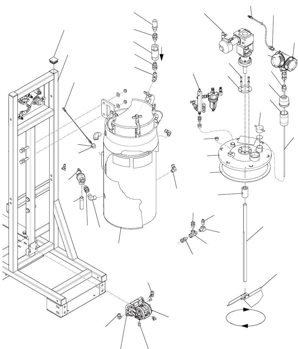
Feed Module (24P883)
Page 1 of 2
WLF
218
219
217
269
300
202
272
268, 215
265
266
215
206
271
270
273
267
243
201
247
216
213 211
209
207
208
210
211
212
213
213
222220
251
252
252
254
233
253
230
254
219a
298
297
Turns clockwise
as viewed from
the top
219
246
Parts
3A2989G 41
Page 2 of 2
ti20161c
225
224
249
250
250
276
226
224
277
227
229
228
261
223
224
260
259 258
257
231
262
227a
227b
227c
213
Parts
42 3A2989G
Feed Module (24P883)
--- Not for sale.
◆See Supply Systems manuals 313526 and 313527
for detailed instructions and parts list for the S20
Supply Unit (262868).
★Included in radar level sensor kit 24T052. See
Replace Radar Level Sensor on page 24.
NOTE: 24T052 Level sensor with the blue head
replaces the 24P884 sensor with the red head.
24T052 includes #298
Ref Part Description Qty
201 --- FRAME 1
202 24M683 TANK, pressure, assembly 1
203 --- BOLT, hex head, 3.25 in. long,
5/8-11
4
204 111841 WASHER, plain 5/8 8
205 --- NUT, self-locking hex, nylon
insert, 5/8-11
4
206 16R869 COVER, tank wrap 1
207 --- BUSHING, pipe, hex head,
3/4 npt x 1/8 npt, steel
1
208 126351 FITTING, compression, thermo-
couple
1
209 126381 SENSOR, RTD, 1k ohm, 4 pin,
3in.
1
210 126898 FITTING, elbow 2
211 295847 FITTING, elbow, 90, 3/4 mpt 2
212 16T481 VALVE, check (see page 57) 1
213 157785 FITTING, swivel 4
215 171988 GASKET, inspection cap 1
216 16T619 FITTING, nipple, thread on one
end
1
217 24P885 AGITATOR, assembly, air (see
page 51)
1
218 --- MANIFOLD, assembly, air (see
page 53)
1
219 24T052 SENSOR ASSEMBLY, level 1
220 D11021 PUMP, diaphragm 1
221 100016 WASHER, lock 4
222 102040 NUT, lock, hex 4
223 262860 PANEL, assembly, air 1
224 113796 SCREW, flanged, hex head 8
225 16R871 BOTTLE, overflow, 1/2 npt 1
226 16T525 HEATER, fluid, 240V, Viscon LT 1
227◆262868 SUPPLY UNIT, 40:1, 0 volt, S20,
20L
1
227a P40DCS PUMP AND MOTOR, see man-
ual 312376
1
227b 257620 S20 RAM, see 313527 1
227c 257727 PLATEN, pail, see 313527 1
228 GC2041 WASHER, flat, std, 1/2 4
229 100017 SCREW, cap, hex head 4
230 117426 INSERT, tube 6
231 104633 VALVE, pilot 1
232 --- SEALANT, pipe, stainless steel 1
233 103475 FITTING, tee, pipe 1
234 --- TUBE, 0.375 in. (9.5mm) ID red
nylon
3.8
235 --- TUBE, 0.375 in. (9.5mm) ID blue
nylon
4.2
236 205418 HOSE, coupled 1
237 109130 HOSE, coupled, 48 in. 1
238 16P244 HOSE, coupled, 3 feet 3
239 15B772 HOSE, air, 18 inch 3
240 054172 TUBE, nylon, round 12
241 054753 TUBE, nylon, round, black 8
242 --- TUBE, 0.275 in. ID black nylon 5.5
243 115313 PLUG, tube 6
246 215241 HOSE, 3/4 in. x 6 ft, 6000 psi
(41 MPa, 410 bar)
1
247 16T244 VALVE, pressure relief, 3/4 in.
female npt
1
248 --- TIE, cable, 14 in. 20
249 108126 FITTING, tee, street 1
250 126899 FITTING, compression, straight 2
251 112782 ELBOW, swivel, 90 degree 1
252 126897 FITTING, elbow 2
253 115764 FITTING, elbow, 90 degree 1
254 190451 UNION, adapter 2
255 --- LABEL, part description 1
257 116395 FITTING, swivel, elbow 1
258 103656 FITTING, pipe, hex 1
259 198171 FITTING, elbow 1
260 593538 VALVE, shuttle 1/8 nptf 1
261 112781 ELBOW, swivel, 90 degree 1
262 24K976 MUFFLER, 1/4 npt 1
263 100505 BUSHING, pipe 1
264 155665 UNION, adapter 1
265 16R985 FITTING, nipple, 2 npt 1
266 16R983 FITTING, adapter, 2 npt to
3/4 npt
1
267 24P837 GASKET, agitator 1
268 210575 CAP, filler 1
269 16T245 COUPLING, shaft, one piece
clamp
1
270 16T396 SHAFT, agitator, lower 1
271 257604 BLADE ASSEMBLY 1
272 102726 PLUG, pipe headless 1
273 109212 SCREW, socket cap head 1
274 115219 FITTING, tee, 1/4 npt 1
275 262820 KIT, fluid outlet, flexible 1
276 126900 CONNECTOR, male 1
277 126692 CONNECTOR, male 1
296 156172 FITTING, union, swivel 1
297 260067 FITTING, strain relief 1
298★127172 CABLE, M12, 5-pin, 4-wire 1
299 102726 PLUG, pipe, headless 1
300 117571 GASKET, santoprene 1
Ref Part Description Qty
Parts
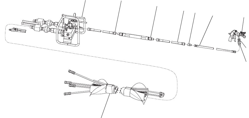
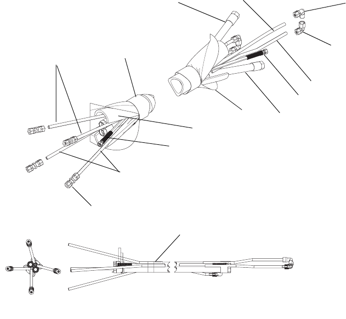
3A2989G 43
Heated Hose Bundle
16T121 - 3/4 in. x 1/2 in. (included in model 262869)
16T122 - 3/4 in. x 3/4 in. (included in model 24W626)
--- Not for sale.
◆Not shown.
310b
310c
302 (red)
305 (blue)
301
308
306
310a
302
305
303
303
307
304
309
ti20243a
Ref Part Description Qty
301 H67550 HOSE, coupled, 3/4 in., 6500 psi;
Model 16T121 - Qty 1
Model 16T122 - Qty 2
302 16X027 KIT, tube, 0.375 (9.5mm) ID red
nylon
2
303 H42550 HOSE, coupled, 4500 psi, 1/4 in. ID,
50 ft (15.2 m)
1
304 --- LABEL, identification 1
305 16X028 KIT, tube, 0.375 in. (9.5mm) ID blue
nylon
2
306 --- TAPE, electrical 1
307 --- TUBE, insulation, 2-5/8 in. ID, 50 ft
(15.2 m)
1
308 H75050 HOSE, coupled, 7250 psi, 1/2 in. ID,
50 ft (15.2 m); Model 16T121 only
1
309 16T138 JACKET, scuff, 50 ft (15.2 m) 1
310 16U666 KIT, tube fittings 1
310a 126894 UNION, 1/2 in. tube x 1/2 in. tube 4
310b 126898 ELBOW, 1/2 in. tube x 1/2 nptm 2
310c 126896 ELBOW, 1/2 in. tube x 1/2 nptf 2
311◆16U111 KIT, fittings, hose connection 1
311a◆C20487 NIPPLE, hex 2
311b◆158491 NIPPLE 1
311c◆156823 UNION, swivel 2
311d◆156971 NIPPLE, short 1
Ref Part Description Qty
Parts
44 3A2989G
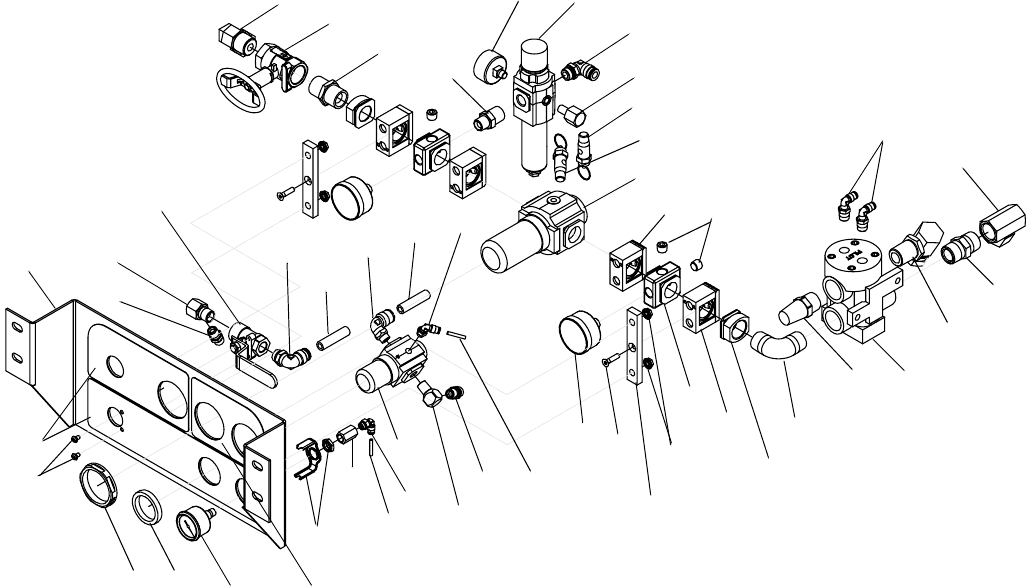
Base System (262878, 24W648) Subassemblies
System Air Controls Module (255761)
NOTE: For Feed Module Air Panel (262860) parts, see page 55.
★Parts included in Air Controls Kit 255772 (purchase sepa-
rately).
--- Not for sale.
604
640 631
633
611
617
615
613
606
618
603
609
629
625
620
621 622
617
612
616
610
607 608
635
633 634
635
629
627
628
627
632
636
626
638
632
637
619
618
630 641
646
644
645
642
642
643
647
613
Ref. 27
Ref. Part Description Qty.
603 157350 NIPPLE, pipe; 1/2 x 3/8 npt 1
604 108307 ELBOW, pipe, male 1
606 101689 GAUGE, press, air 2
607 117346 VALVE, ball, vented 1
608 114316 ELBOW, male, swivel 1
609* 114109 ELBOW, male, swivel; 1/4 OD tube 2
610 158962 ELBOW, street; 1/4(f) x 1/8(m) 1
611 116643 VALVE, safety, relief, air 1
612 100721 PLUG, pipe 3
613 119992 PIPE, nipple; 3/4 x 3/4 npt 2
615 156589 ADAPTER, union; 90 deg. 1
616 113911 GAUGE, pressure, air 1
617 160327 ADAPTER, union; 90 deg. 2
618 15T119 LABEL, control 1
619 --- BRACKET, air controls 1
620 15R437 BRACKET, adapter, air controls 2
621 121432 SCREW, machine, hex flat head 2
622 115942 NUT, hex, flange head 4
625 116513 REGULATOR, air 1
626 121457 VALVE, ball, air, panel mounted 1
627 121424 GAUGE, pressure, panel mount, 1.5 in. 1
628 100451 COUPLING 1
629 114151 ELBOW, male, swivel 2
630 100264 SCREW, machine, pan head 2
631 116514 NUT, regulator 1
632 054760 TUBE, polyurethane, round, black; 1.25
in.
-
633 --- TUBE, polyurethane, round; 0.6 ft. -
634 100840 ELBOW, street 1
635 162453 FITTING; 1/4 npsm x 1/4 npt 2
636 114114 ELBOW, male, swivel 1
637 114128 ELBOW, male, swivel 1
638 164259 ELBOW, street 1
640★122336 NUT, panel, regulator 1
641★113440 ADAPTER 2
642★113431 CLAMP, quick 4
643★113442 BLOCK, porting 2
644★15R488 REGULATOR 1
644a 123454 FILTER, element; 5 micron 1
645★15R487 REGULATOR 1
646★15R486 MUFFLER 1
647★15R485 VALVE, dual pilot 1
Ref. Part Description Qty.
Parts
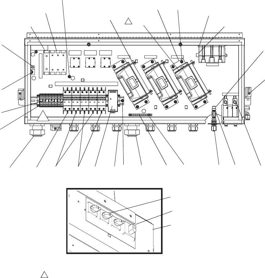
3A2989G 45
Junction Box (24N598)
B HOSE A
Set High Power Temperature Control Module zone addresses on dial
under cover when installing modules (404). Addresses: B Module =1,
Hose Module = 2, A Module = 0.
NOTE: See Electrical Schematics beginning on page 27 for cable
identification.
4
416
417,
407, 408 405b 406 403 407 420 421 426, 427
415, 445
413, 414, 443
402 403
404
418, 419, 423
403, 446
412
411
410
409
401
425
442
405
405a
405f 405c 405e
4
ti20155a
444
442
422,
439
Parts
46 3A2989G
Junction Box (24N598)
--- Not for sale.
▲Replacement Danger and Warning labels, tags and
cards are available at no cost.
zBase electronic components do not have
XM PFP-specific software installed. Therefore, use
software upgrade token (506) to install software
before use.
†Parts available in Fluid Control Module Cube Kit
24R902. Kit includes items 413, 415, 445, software
token (506), and instructions.
◆Parts available in High Power Temperature Control
Module Kit 24R903. Kit includes items 404, software
token (506), and instructions.
Ref Part Description Qty
401 --- ENCLOSURE 1
402 --- BRACKET, module 3
403 114231 NUT, lock, hex 16
404◆255774 MODULE, GCA, HPTCM 3
405 --- MODULE, breaker 1
405a 126382 BLOCK, terminal 8
405b 126129 BREAKER, 25A 1
405c 126130 BREAKER, 30A 2
405d 126684 JUMPER, red 3
405e 126453 POWER SUPPLY, 24V 1
405f 126128 BREAKER, 20A 2
406 121603 GRIP, cord, 0.51-0.71, 3/4 6
407 255047 BUSHING, strain relief, M40
thread
2
408 255048 NUT, strain relief, M40 thread 2
409 15U423 SWITCH, 2p, 25a 3
410 123967 KNOB, operator disconnect 1
411 123968 SWITCH, disconnect, 100 amp 1
412 123969 SWITCH, disconnect, 100 amp 1
413† 289697 MODULE, GCA, cube, base 1
414 104371 SCREW, cap sch 10 x 0.375 4
415z† 289696 MODULE, GCA, cube, FCM 1
416 117666 TERMINAL, ground 1
417 115942 NUT, hex, flange head 1
418 15U651 BRACKET, high power, GCA 6
419 117831 SCREW, machine, pan head 12
420 --- BAR, ground 1
421 109466 NUT, lock, hex 2
422 104387 SCREW, machine, pan head 4
423 113161 SCREW, flange, hex head 6
425 126496 CONNECTOR, thru, M12, male x
female, reverse key
1
426 --- MODULE, solenoid 1
426a 121636 VALVE, solenoid 2
426b 15A798 GASKET, outlet 1
426c 15A799 GASKET, inlet 1
427 106084 SCREW, machine, pan head 2
428 125789 CABLE, CAN, female / female,
0.5 m
2
429 123422 CABLE, CAN, 5-pin, female /
female, 0.4 m
2
430 121615 HARNESS, splitter, M8, 4-pin,
female/female/male, 3 m
1
432 126495 CABLE, splitter, 4-20ma, 2 circuit 1
433 124273 CONNECTOR, splitter 1
434 --- STRAP, tie 14
435 126494 CABLE, M12, 5p, 4wire with drain 2
436 121806 CABLE, solenoid 2
437 --- STRIP, foam, neoprene 10
438 16T147 CABLE, can power, M12 female,
pigtail
1
439 16P626 LATCH, enclosure 4
440▲16T278 LABEL, multi-purpose; including
warnings text, shock arrow,
ground symbol, and various infor-
mational stickers
1
442 16T072 ADAPTER, cable, CAN 1
443 126687 SCREW, machine, pan head 1
444 558685 WASHER, lock, external type, 1/4 1
445† 277674 ENCLOSURE, cube door 1
446 555629 WASHER, lock, external type, #10 2
Ref Part Description Qty
Parts
3A2989G 47
Control Box (255771)
501
502
504c
504a, 504d
532
532 538
521
504e
504f
510
528
529
530
540
541
543
515
524, 525
517
507
535
514
509
526
508
545
503
502
523
522
520
536
504g
501
538
537
544
533 534 526
527
504b
542
542
551
543
504h
539
519c
543
526
ti18050a
546
Ref. Part Description
Qty
.
501 --- BOX, control 1
502 --- LABEL, control display 1
503† 24R899 KIT, replacement, USB; includes
519 and 506
1
504z257484 MODULE, display, kit
504a 15M483 SHIELD, membrane, display (qty.
10)
1
504b --- SCREW, pan head; #6 x 7/8 in. 4
z504c 288997 CASE, rear, display module, IS
version
1
504d 255727 CASE, front, data module 1
504e 277463 COVER, access, low level display 1
504f 113768 SCREW, socket, flat head 4
504g 15R458 GASKET, control, front panel 1
▲504h 15W958 LABEL, warning, battery 1
505† 24R897 KIt, replacement, display; includes
504 and 506
1
506* 16P644 TOKEN, software 1
507† 24R898 KIT, replacement, FCM; includes
518 and 506
1
508 --- SCREW, pan head 4
509 256555 MODULE, solenoid, IS version 1
509a 121636 VALVE, solenoid, din connector 4
509b 15A798 GASKET, solenoid, outlet 1
509c 15A799 GASKET, solenoid, inlet/exhaust 1
510 106084 SCREW, machine, pan head 2
514 15R379 GASKET, box, control 1
515 --- LABEL 1
516❄15B056 LABEL, air motor/dosing valve 1
517 122000 ALARM, panel mount 1
518z255920 MODULE, fluid control 1
Ref. Part Description
Qty
.
Parts
48 3A2989G
▲Replacement Danger and Warning labels, tags, and
cards are available at no cost.
--- Not for sale.
❄Not shown.
zBase electronic components do not have
XM PFP-specific software installed. Therefore, use
software upgrade token (506) to install software
before use.
† Includes software token (506) and instruction sheet.
519z257088 MODULE, USB, assy.
519a 289899 BASE 1
z519b 289900 MODULE, USB 1
519c 277674 DOOR, module 1
520 121618 SWITCH, start, push button,
green
1
521 15R324 HARNESS, USB, plug/bulkhead;
32 in.
1
522 121619 SWITCH, stop, push button, red 1
523 121617 SWITCH, 2 position, key, controls 1
523a❄123412 KEY, replacement (pair)
524 117745 BUSHING, strain relief 1
525 117625 NUT, locking 1
526 113505 NUT, keps, hex head 6
527 15B090 WIRE, grounding, door 1
528 --- WASHER, lock, external, 1/4 in. 1
529 15R343 CLAMP, ground, electrical 1
530 --- WIRE, copper 3
531❄172953 LABEL, designation 2
532 120493 LATCH, mounting 3
533 15H189 BOOT, wire feed through 1
534 15G816 COVER, plate, wire 1
535 110637 SCREW, machine, pan head 4
536 15R325 COVER, dust, bulkhead
receptacle
1
537 120494 BLOCK, switch, normally open 2
538 120495 BLOCK, switch, normally closed 1
539 15M974 HARNESS, key switch 1
540 15M975 HARNESS, start/alarm 1
541 15M976 HARNESS, stop 1
542 15M977 HARNESS, solenoid 2
543 121988 RETAINER, routing, wire harness 4
544 195875 SCREW, machine, pan head 1
545 102063 WASHER, lock 1
546 15U542 CABLE, motor 2
551▲LABEL, warning, USB 1
15X214 English
15X393 All languages
552❄122829 CONDUIT; 0.75 ft. -
Ref. Part Description
Qty
.
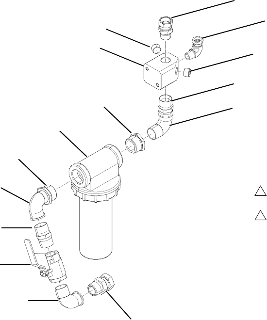
Parts
3A2989G 49
Air Filter (24P899)
--- Not for sale.
◆Not shown.
ti20218a
Apply PTFE tape and/or pipe sealant to all
non-swiveling pipe threads.
Orient fittings approximately as shown.
1
2
706
707
711
703
704
711
705
702
701
702
703
704
708
703
709
Ref Part Description Qty
701 16T236 FILTER, air, 1-1/4, auto drain 1
701a◆106204 FILTER ELEMENT 1
702 C19662 BUSHING, 1-1/4 x 1 npt carbon
steel
2
703 110300 FITTING, elbow, street, pipe 3
704 158585 FITTING, nipple 2
705 16R951 MANIFOLD, air distribution 1
706 157785 FITTING, swivel 1
707 C19024 FITTING, elbow, swivel 1
708 113163 VALVE, ball, vented, 1.00 in. 1
709 160022 FITTING, union, adapter 1
710 --- SEALANT, pipe, stainless steel 1
711 100361 PLUG, pipe 2
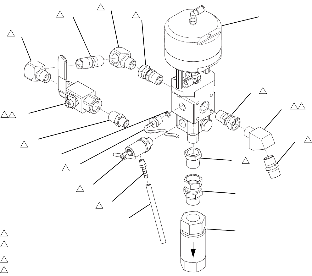
Parts
50 3A2989G
Ratio Control Valve Assemblies
† See Dosing Valve Instructions - Parts manual refer-
enced on page 3 for further details.
Apply pipe sealant to all non-swiveling pipe threads.
Position valve (832) with barbed fitting (833) oriented as shown,
position elbow (837) as shown.
Torque until nut (831) bottoms out in housing.
Flip ball valve handle retainer (855). Handle to face forward in
open position.
1
8
14
15
836
855
852
852
854
853
839
831
1
15
1
1
1
1
1
14
832
8
833
8
851
857 1
856
836 1
8371
840 1
8
801
ti20219a
858
Ref Part Description Qty
801† 255478 VALVE, dosing 1
831 15M669 SENSOR, pressure, fluid outlet 1
832 262872 VALVE, pressure, bleed, PFP 1
833 116746 FITTING, barbed, plated 1
836 156684 FITTING, union, adapter 2
837 15M987 FITTING, elbow, 60 degree 1
839 121399 PACKING, o-ring 1
840 158491 FITTING, nipple
(B side only - Qty 1)
(A side only - Qty 2)
851 116750 TUBE, nylon 1
852 158683 FITTING, elbow, 90 degree 2
853 159239 FITTING, nipple, pipe, reducing
(B side only)
1
854 156877 FITTING, nipple, long 1
855 262739 VALVE, ball, 1/2 in. 1
856 16T481 VALVE, check; see page 57 1
857 502033 FITTING, bushing, pipe 1
858 157785 FITTING, swivel 1
Ref Part Description Qty
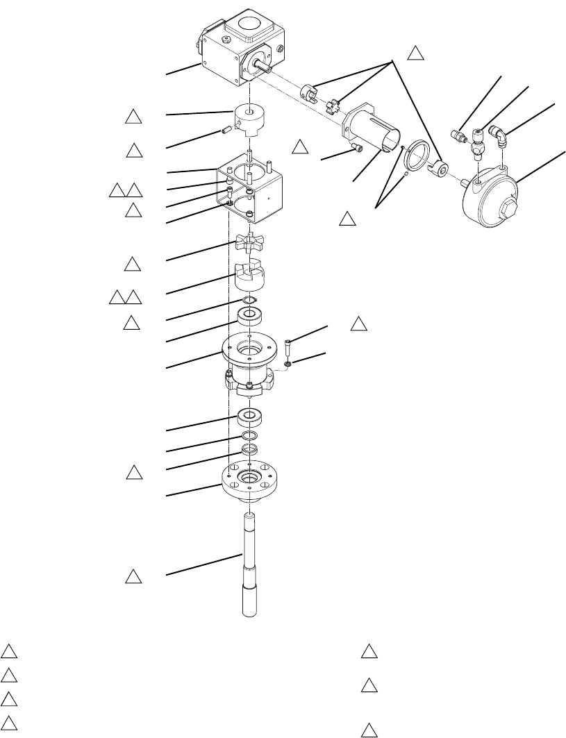
Parts
3A2989G 51
Feed Module (24P883) Sub-Assemblies
Air Powered Agitator (24P885)
Apply pipe sealant to all non-swiveling pipe threads.
Apply low strength threadlocker.
Apply blue thread locker.
Remove four screws from gear reducer (915), pass them
through bracket (912) and back into gear reducer (915) then
torque to 150-170 in-lb (17-19 N•m).
Leave a 0.015 in. gap between each half of couplings (910,
911, 916, 917).
When ordering a replacement coupling: Remove set screw
supplied with couplings (910, 916) and discard. Replace with
set screw (931).
Open side of u-cup seal (903) must face down inside
housing (902).
1
2
3
4
5
7
8
917
918
923
924
925
922
919
921
915
907
916
914
912
913
911
910
909
905
906
908
913
905
904
903
902
901
5
2
2
5
7
915
43
3
5
7
5
3
8
7
7
Parts
52 3A2989G
Air Powered Agitator (24P885)
--- Not for sale.
▲Replacement Danger and Warning labels, tags and
cards are available at no cost.
Ref Part Description Qty
901 16P919 SHAFT, agitator, upper 1
902 16U219 HOUSING, agitator 1
903 --- SEAL, 0.875 in. ID x 1.125 in. OD,
PTFE
1
904 --- SPACER, shaft, agitator, ASME 1
905 122774 BEARING, ball, 3/4bore x 1-3/4 dia. x
1/2
2
906 16P920 HOUSING, bearing, agitator 1
907 --- SCREW, socket head set screw,
5/16-18 x 0.75
2
908 112222 SCREW, socket cap head 4
909 --- RING, retaining, external, 0.750 in. 1
910 122761 HOUSING, alignment, hub 1
911 122760 COUPLING, alignment, disk, TPE 1
912 16P922 BRACKET, adapter, agitator 1
913 C19209 WASHER, lock 8
914 101682 SCREW, socket cap head 4
915 181794 GEAR, reducer 1
916 16P923 COUPLER, adapter 1
917 100828 COUPLING, flexible 1
918 16T063 COLLAR, mounting 1
919 116940 SCREW, cap, socket head, 5/16-18 2
920 181849 COLLAR 1
921 101118 SCREW 2
922 111310 MOTOR, air, rotary 1
923 115841 FITTING, elbow 1
924 206264 VALVE, needle 1
925 191872 FITTING, nipple, reducing 1
926 --- SEALANT, pipe, stainless steel 1
927 --- SEALANT, low strength thread locker 1
928 --- SEALANT, blue thread locker 1
929▲15A722 TAG, warning, agitator 1
930▲16A614 TAG, label, caution 1
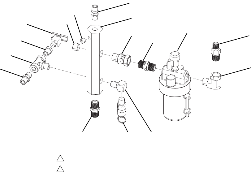
Parts
3A2989G 53
Tank Air Manifold Assembly
--- Not for sale.
1008
Apply pipe sealant to all non-swiveling pipe threads.
Orient all fittings as shown.
1
2
1001
1005
1013
1004
1003
1002
100610071003
1010
1012
1011
1013
1009
1008
Ref Part Description Qty
1001 189016 MANIFOLD, air, inlet 1
1002 155665 UNION, adapter 1
1003 156849 PIPE, nipple 2
1004 214847 LUBRICATOR, air line 1
1005 165198 FITTING, nipple, reducing 1
1006 100840 FITTING, elbow, street 1
1007 103347 VALVE, safety, 100 psi 1
1008 156971 FITTING, nipple, short 2
1009 108638 FITTING, pipe, tee 1
1010 101759 FITTING, drain cock 1
1011 101754 PLUG, pipe 1
1012 100139 PLUG, pipe 1
1013 100030 BUSHING 1
1014 111856 FITTING, elbow, street 1
1015 --- SEALANT, pipe, stainless steel 1
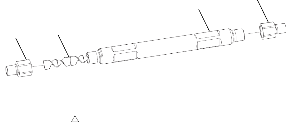
Parts
54 3A2989G
Static Mixer (16T316)
--- Not for sale.
1303
1303
1301
1302
Apply pipe sealant to all non-swiveling pipe threads.
1
Ref Part Description Qty
1301 --- TUBE, mixer 1
1302 24P886 MIXER, 12 element, stainless steel 1
1303 16T315 BUSHING, reducing 3/4 nptf x
1/2 npt
2
1304 --- SEALANT, pipe, stainless steel 1
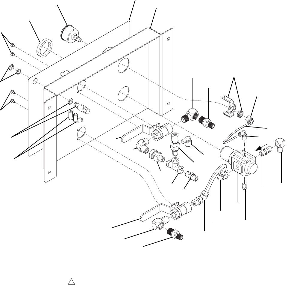
Parts
56 3A2989G
Air Panel (262860)
--- Not for sale.
Ref Part Description Qty
1101 --- BRACKET, air control 1
1102 --- LABEL, instructions 1
1103 121424 GAUGE, pressure, panel mount,
1.5 in.
1
1104 15T498 FITTING, 90 degree, swivel,
5/32 in. tee x 1/8 in. female npt
1
1105 116513 REGULATOR, air 1
1106 121141 FITTING, elbow, swivel, 3/8 tee,
1/4 in. male npt
1
1109 198171 FITTING, elbow 1
1110 100403 PLUG, pipe 1
1111 121457 VALVE, ball, air, panel mounted 2
1113 155699 FITTING, elbow, street 3
1114 165198 FITTING, nipple, reducing 3
1115 104984 FITTING, tee, pipe 1
1116 157705 UNION, swivel 1
1117 156971 FITTING, nipple, short 1
1118 206264 VALVE, needle 1
1119 114367 FITTING, tube, qd, 90 degree
elbow
1
1120 109544 FITTING, elbow, pipe, male 1
1121 110914 VALVE, button, push 1
1122 100264 SCREW, mach, panhead 4
1123 116514 NUT, regulator mount 1
1124 109193 FITTING, tube, male, elbow 2
1125 16F151 FITTING, elbow, swivel, 3/8 tee,
3/8 npt
1
1126 --- SEALANT, pipe, stainless steel 1
1127 054134 TUBE, nylon, 3/8 in. OD 1.1
1128 517305 TUBE, nylon, 5/32 in. OD 0.7
1129 106495 VALVE, check, brass, 1/4 MBE 1
1130 100840 FITTING, elbow, street 1
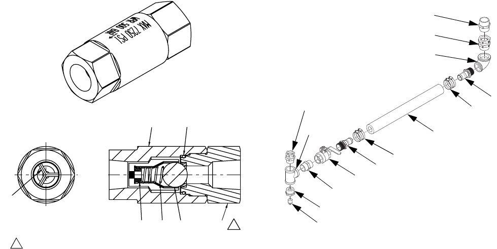
Parts
3A2989G 57
Check Valve (16T481)
--- Not for sale.
Flexible Fluid Connection Kit (262820)
Ref Part Description Qty
1201 --- NUT, seat 1
1202 102595 PACKING, o-ring 1
1203 100279 BALL, metallic 1
1204 108361 SPRING, compression 1
1205 --- HOUSING, ball check 1
1206 181492 GUIDE, ball 3
1207 181535 RETAINER, spring 1
1205
1201
1207 1204 1203
1202
1206
1
Torque to 75-80 ft-lb (102-108 N•m).
1
Ref Part Description Qty
1401 120291 PIPE, elbow female 1
1402 125995 FITTING, hose, barbed, 1-1/2 npt 2
1403 126320 HOSE, 1-1/2 ID, 200 psi, 3 ft 1
1404 126889 CLAMP, hose 2
1405 121440 VALVE, ball, 1-1/2 npt 1
1406 121441 FITTING, nipple, hex, 1-1/2 npt 1
1407 121443 FITTING, tee, 1-1/2npt 1
1408 101496 BUSHING, pipe 1
1409 104663 PLUG, pipe 1
1410 121445 SWIVEL, reducing, 1-1/2 x 1-1/4 1
1411 121436 FITTING, swivel, male, 2 in. 1
1412 121435 FITTING, nipple, hex, 2 in. 1
1406
1405
1402
1404
1403
1404
1402
1401
1411
1412
1410
1408
1409
1407

Technical Data
58 3A2989G
Technical Data
XM PFP
US Metric
Mix Ratio Range 1:1-10:1 (in 0.01 increments)
Ratio Tolerance Range (before alarm) +/- 5%
Maximum Flow Rate (measured with oil) 3 gallons per minute 13.6 liters per minute
Fluid Viscosity Range Handles mastic materials which are loaded into heated tanks
with ram-fed priming piston pumps
Air Inlet 1 in. npt(f)
Fluid Inlets Pail (Pail Feed RAM Pumps)
Maximum Fluid Working Pressure for A and B
Materials
6000 psi 41 MPa, 414 bar
Maximum Fluid Working Pressure for Flushing
Fluid
4500 psi 31 MPa, 7 bar
Maximum Fluid Working Pressure for Heating
Fluid
100 psi 0.7 MPa, 7 bar
Maximum Fluid Temperature 160°F 70°C
System Inlet Supplied Air Pressure Range 80-150 psi 0.5-1.0 MPa, 5.5-10.3 bar
Maximum Pump Air Pressure 100 psi 0.7 MPa, 7 bar
Maximum Tank Air Pressure 90 psi 0.6 MPa, 6 bar
Air Filtration 40 micron main filter, 5 micron control air filter
Ambient Operating Temperature Range 32 to 130°F 0 to 54°C
Ambient Storage Temperature Range 30 to 160°F -1 to 71°C
Environmental Conditions Rating Altitude up to 13,123 ft Altitude up to 4000 m
Sound Pressure * 86 dBA at 100 psi 86 dBA at 0.7 MPa, 7 bar
Sound Power ** 98 dBA at 100 psi 98 dBA at 0.7 MPa, 7 bar
System Weight (empty, no fluid) 2175 lb 987 kg
Air Consumption
Minimum 100 scfm 2.8 meter
3
/min
Maximum 250 scfm 7.1 meter
3
/min
Typical Application 125-175 scfm 3.5-5.0 meter
3
/min
Power Requirements
Voltage (can be set with jumpers) Option 1: 220-240V, 3 phase DELTA (3 wire plus ground)
Option 2: 380-400V, 3 phase WYE (4 wire including neutral
plus ground)
Wattage 18,400 watts (23,400 with optional flush water heater)
Amps 240V, 3-phase models: 65 Amps per phase full load
380V, 3-phase models: 38 Amps per phase full load

Technical Data
3A2989G 59
Wetted Parts
Suction Tube (Flush) Aluminum
Tanks Stainless Steel
Flush Pump Carbide, PTFE, stainless steel, UHMWPE
Hoses Nylon
Pumps (A, B and Feed Pail) Carbon steel, alloy steel, 303, 440, 17-ph grades stainless
steel, zinc and nickel plating, ductile iron, tungsten carbide,
PTFE
Dosing Valves Carbon Steel, nickel plating, carbide, polyethylene, leather
Manifold Carbon steel, nickel plating, carbide, 302 stainless steel,
PTFE, UHMWPE
Mixer Stainless steel housing with stainless elements
Approvals
Machine CE, ETL
Pressure Tanks ASME, PED
Notes
* Sound pressure measured 3.3 feet (1 meter) from equipment.
** Sound power measured per ISO-9614-2.
XM PFP
US Metric
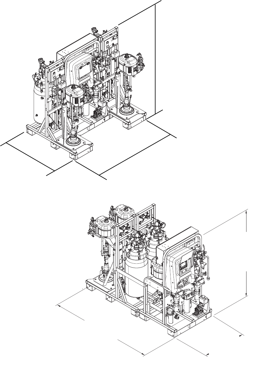
Technical Data
60 3A2989G
Dimensions
Min: 70 in.
(1780 mm)
Max: 84 in.
(2130 mm)
76 in.
(1930 mm)
52 in.
(1320 mm)
WLE
Min: 70 in.
(1780 mm)
Max: 84 in.
(3130 mm)
38 in.
(965 mm)
104 in.
(2640 mm)

Notes
3A2989G 61
Notes

All written and visual data contained in this document reflects the latest product information available at the time of publication.
Graco reserves the right to make changes at any time without notice.
For patent information, see www.graco.com/patents.
Original instructions. This manual contains English. MM 3A2989
Graco Headquarters: Minneapolis
International Offices: Belgium, China, Japan, Korea
GRACO INC. AND SUBSIDIARIES • P.O. BOX 1441 • MINNEAPOLIS MN 55440-1441 • USA
Copyright 2012, Graco Inc. All Graco manufacturing locations are registered to ISO 9001.
www.graco.com
Revision G, January 2015
Graco Standard Warranty
Graco warrants all equipment referenced in this document which is manufactured by Graco and bearing its name to be free from defects in
material and workmanship on the date of sale to the original purchaser for use. With the exception of any special, extended, or limited warranty
published by Graco, Graco will, for a period of twelve months from the date of sale, repair or replace any part of the equipment determined by
Graco to be defective. This warranty applies only when the equipment is installed, operated and maintained in accordance with Graco’s written
recommendations.
This warranty does not cover, and Graco shall not be liable for general wear and tear, or any malfunction, damage or wear caused by faulty
installation, misapplication, abrasion, corrosion, inadequate or improper maintenance, negligence, accident, tampering, or substitution of
non-Graco component parts. Nor shall Graco be liable for malfunction, damage or wear caused by the incompatibility of Graco equipment with
structures, accessories, equipment or materials not supplied by Graco, or the improper design, manufacture, installation, operation or
maintenance of structures, accessories, equipment or materials not supplied by Graco.
This warranty is conditioned upon the prepaid return of the equipment claimed to be defective to an authorized Graco distributor for verification of
the claimed defect. If the claimed defect is verified, Graco will repair or replace free of charge any defective parts. The equipment will be returned
to the original purchaser transportation prepaid. If inspection of the equipment does not disclose any defect in material or workmanship, repairs
will be made at a reasonable charge, which charges may include the costs of parts, labor, and transportation.
THIS WARRANTY IS EXCLUSIVE, AND IS IN LIEU OF ANY OTHER WARRANTIES, EXPRESS OR IMPLIED, INCLUDING BUT NOT
LIMITED TO WARRANTY OF MERCHANTABILITY OR WARRANTY OF FITNESS FOR A PARTICULAR PURPOSE.
Graco’s sole obligation and buyer’s sole remedy for any breach of warranty shall be as set forth above. The buyer agrees that no other remedy
(including, but not limited to, incidental or consequential damages for lost profits, lost sales, injury to person or property, or any other incidental or
consequential loss) shall be available. Any action for breach of warranty must be brought within two (2) years of the date of sale.
GRACO MAKES NO WARRANTY, AND DISCLAIMS ALL IMPLIED WARRANTIES OF MERCHANTABILITY AND FITNESS FOR A
PARTICULAR PURPOSE, IN CONNECTION WITH ACCESSORIES, EQUIPMENT, MATERIALS OR COMPONENTS SOLD BUT NOT
MANUFACTURED BY GRACO. These items sold, but not manufactured by Graco (such as electric motors, switches, hose, etc.), are subject to
the warranty, if any, of their manufacturer. Graco will provide purchaser with reasonable assistance in making any claim for breach of these
warranties.
In no event will Graco be liable for indirect, incidental, special or consequential damages resulting from Graco supplying equipment hereunder, or
the furnishing, performance, or use of any products or other goods sold hereto, whether due to a breach of contract, breach of warranty, the
negligence of Graco, or otherwise.
FOR GRACO CANADA CUSTOMERS
The Parties acknowledge that they have required that the present document, as well as all documents, notices and legal proceedings entered into,
given or instituted pursuant hereto or relating directly or indirectly hereto, be drawn up in English. Les parties reconnaissent avoir convenu que la
rédaction du présente document sera en Anglais, ainsi que tous documents, avis et procédures judiciaires exécutés, donnés ou intentés, à la suite
de ou en rapport, directement ou indirectement, avec les procédures concernées.
Graco Information
For the latest information about Graco products, visit www.graco.com.
TO PLACE AN ORDER, contact your Graco distributor or call to identify the nearest distributor.
Phone: 612-623-6921 or Toll Free: 1-800-328-0211 Fax: 612-378-3505
