Graco Manzel Hp 50 60 High Pressure Lubricators Users Manual
2015-04-02
: Graco Graco-Manzel--Hp-50-Hp-60-High-Pressure-Lubricators-Users-Manual-685742 graco-manzel--hp-50-hp-60-high-pressure-lubricators-users-manual-685742 graco pdf
Open the PDF directly: View PDF ![]() .
.
Page Count: 4
INTRODUCTION
This manual provides operation and service instructions and a
parts list for the “Manzel” Model HP-50 and HP-60 High Pressure
Lubricators, Discharge and Terminal Check Valves.
The high pressure lubricator comprises one to four integral sight
and pump assemblies in a cast iron reservoir. The unit is designed
for direct connection to an electric motor/speed reducer power
source. A “Manzel” terminal check valve is recommended in the
lubrication system. When required to maintain proper oil viscosity,
the reservoir can be fitted with an optional steam or electric
heater.
OPERATING INSTRUCTIONS
1. Oil Level — When necessary, completely fill the lubricator
reservoir with clean filtered lubricant. Three sight glasses,
provided in the reservoir at various levels, permit observation
of fluid level. Oil level should not be allowed to drop below
the bottom sight glass. During the initial filling, the vent plugs
at the top of the pump sight glasses should be removed. This
allows lubricant to rise in the drip tube up to the level of the
oil in the reservoir and reduces the priming re quired at start
up.
2. Pump Priming — If the sight well on the pump does not
contain oil, the pump should be primed. Pumps may be
primed while the lubricator shaft is rotating as follows:
• Adjust the pumping rate to the maximum setting by
turning the adjustment nut on the indicator stem as far
as possible in a clockwise direction.
• Remove the vent plug on top of the sight glass and
fill the housing sight well with oil to 3/8 inch below the
discharge of the drip tube.
• Replace the vent plug. Check the sight glass to
insure that it is properly seated against the O-ring to
prevent air leakage into the sight well.
• Readjust the pumping rate to the desired delivery.
3. Pumping Rate — The pumping rate is indicated at the drip
tube inside the sight glass. During the pump suction stroke,
fluid is drawn into the pump from the sight well. This creates
a partial vacuum in the sight well, permitting atmospheric
pressure in the lubricator reservoir to force an amount of oil
equal to the pump displace ment through the drip tube into the
sight well. The rate is adjustable for each pump assembly by
means of the pump regulator which varies the stroke of the
positive displacement, reciprocating pump assembly.
Caution: The drip tube flow rate is accurate after the
pump has operated long enough to stabilize the pressure
inside the sight well. There is a time lag at start-up, low
pumping rates, and during pump rate changes. Allow
sufficient time to insure an accurate rate indication.
4. Regulating Pump Rate — The pumping rate can be varied
infinitely within the range of minimum to maximum by means
of the graduated pump regulators which project through the
reservoir cover. The regulators are easily adjusted by hand
during the pump suction stroke. Maximum pumping rate
is achieved when the adjustment nut on the sight indicator
stem is turned in a clockwise direction as far as it can go. In
this position the sight indicator stem projects the maximum
distance indicating maximum pumping stroke. When the
adjusting nut is turned in a counter-clockwise direction,
delivery reduces, because of a reduction in pump stroke, until
minimum delivery is obtained.
Note: To retain the hydraulic seal between the plunger
and the cylinder walls, minimum delivery must not go
below 1/2 drop (0.017 cc) per pump stroke.
Manzel® Model HP-50, HP-60
High Pressure Lubricators
SPECIFICATIONS
Plunger Diameter 1/4 in
Max Operating Pressure
HP-50 50,000 psi
HP-60 60,000 psi
Max Pumping Rate 0.133 cc/stroke, base on SAE 40 oil
(approx 4 drops) @ max pressure*
Reservoir Heating
(Optional) Steam or Electric
*Greater pumping rate may be obtained when operating pressure
is below maximum. Increased viscosity results in a slightly lower
pumping rate.
High Pressure Lubricator Product Service/Maintenance
Page 2
L40240
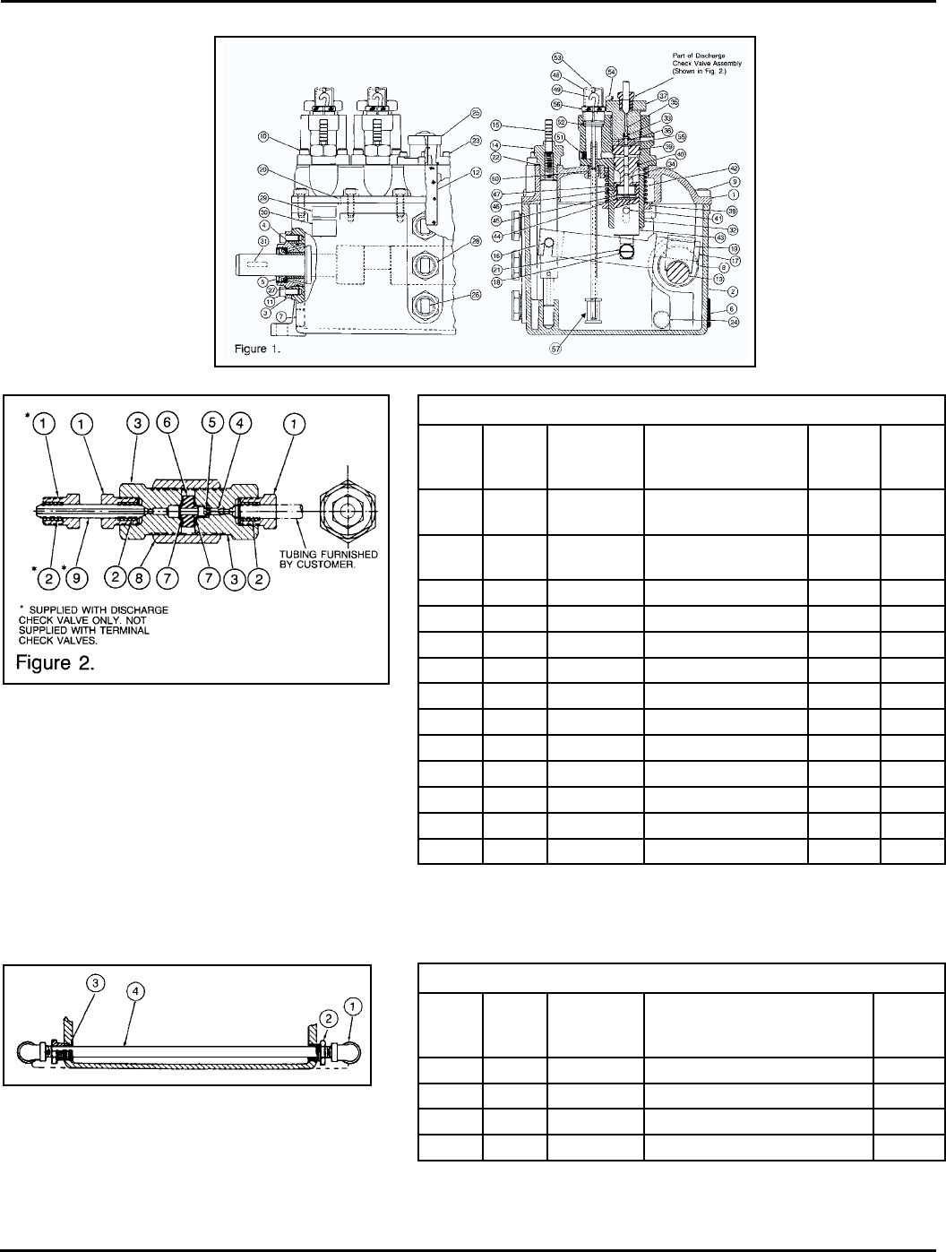
CHECK VALVE PARTS LIST
Figure
& Index
No.
Part No. Old Part No. Description Quantity
Required
Usage
Code
2- 564336 463-280-071 Terminal Check Valve,
HP-50, 3/8 in O.D. Tube 1 D
2- 564335 463-280-021 Discharge Check Valve,
HP-50, 3/8 in O.D. Tube 1 E
-1 556783 446-010-010 Nut, Gland 2 D
-1 556783 446-010-010 Nut, Gland 3 E
-2 556781 446-000-010 Collar 2 D
-2 556781 466-000-010 Collar 3 E
-3 560161 410-700-750 Bonnet, Check Valve 2
-4 556936 458-005-140 Spring, Valve 1
-5 560343 463-920-010 Valve 1
-6 560339 463-910-010 Seat, Valve 1
-7 556747 439-077-080 Gasket, Valve 2
-8 561354 463-860-860 Body, Check Valve 1
-9 558823 446-055-000 Nipple, Check Valve 1 E
Note: Check Valve for 3/8 in tube, other sizes available, refer to factory for parts list
details
Figure 2
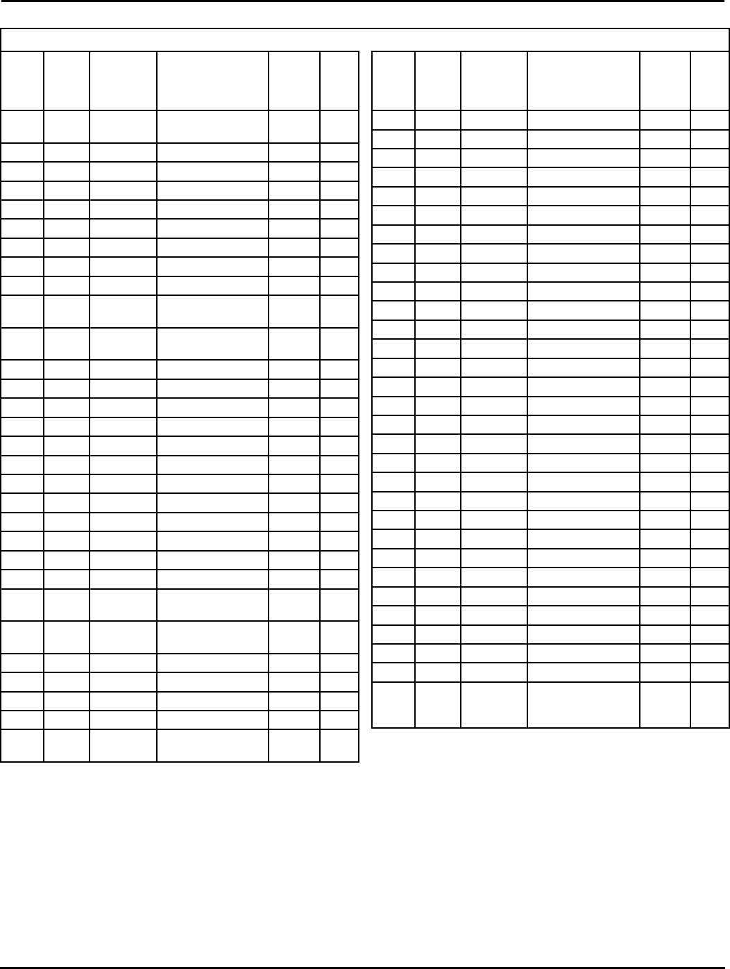
STEAM HEATER COMPONENTS
Figure
& Index
No.
Part No. Old Part No. Description Quantity
Required
3-1 – 412-010-020 Elbow, 1/4 NPT Steam Pipe 2
-2 561335 412-700-040 Seal Plug, Steam Pipe 2
-3 558693 422-051-140 Seal, Steam Pipe 2
-4 560179 412-700-050 Steam Pipe 1
Note: Steam and electric heaters available for all lubricators. Refer to the factory for
detail parts other than those shown above.
Figure 3
Page 3
L40240
High Pressure Lubricator Product Service/Maintenance
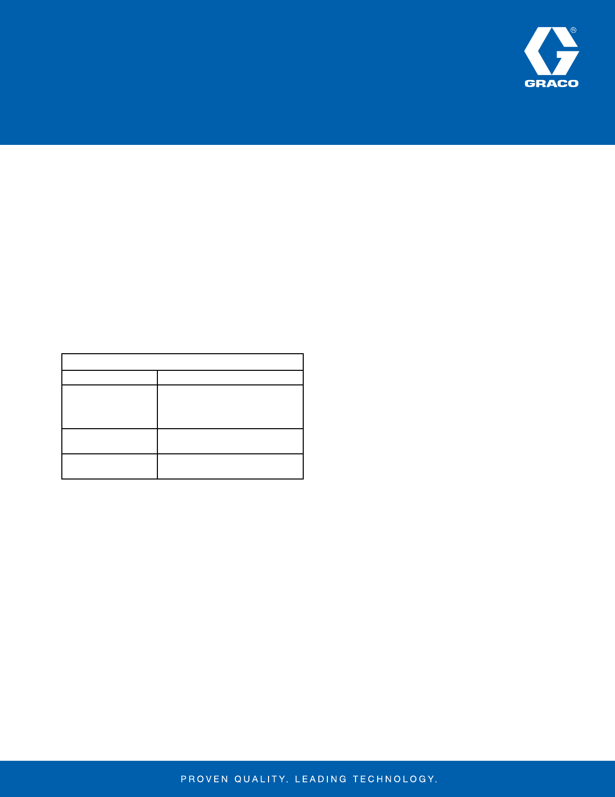
HP-50, HP-60 LUBRICATOR ASSEMBLY PARTS LIST
Figure
&
Index
No.
Part No. Old Part No. Description Quantity
Required
Usage
Code
1- – 469-838-021 Reservoir Assembly,
HP-20-1 1
-1 560398 471-638-000 Cover, Reservoir 1
-2 15M340 469-838-000 Body, Reservoir 1
-3 556340 402-020-020 Bearing, Shaft 2
-4 556343 402-110-000 Bushing, Bearing 2
-5 556579 423-700-000 Seal, Shaft 2
-6 556401 412-140-060 Plug, Heater Opening 1
-7 555444 412-130-150 Plug, Drain Hole 1
-8 560148 402-110-010 Bushing, Reservoir 2
-9 555605 419-170-060 Screws, Reservoir, Cover
& Pump Housing 12
-10 555606 419-170-150 Screws, Pump Housing
End 4
-11 555603 419-170-030 Screws, Bearing 4
-12 557148 473-020-031 Strainer 1
-13 557062 465-920-000 Shaft, Eccentric 1
-14 560157 410-700-440 Nut, Feed Adjusting 4
-15 560281 453-030-000 Rod, Feed Adjusting 4
-16 560171 411-700-050 Pin, Feed Rod 4
-17 560284 453-040-000 Lever, Pump Actuating 4
-18 560169 411-700-030 Pin, Lever 4
-19 560483 484-110-000 Shoe, Pump Actuating 4
-20 560170 411-700-040 Pin, Dowel 2
-21 555552 418-010-230 Ring, Lever Pin 8
-22 556523 421-700-060 Washer, Friction 4
-23 558673 419-150-040 Screw, Reservoir Oil
Filler 4
-24 555450 412-150-060 Plug, Steam Heater
Opening 2
-25 563087 471-638-021 Plate, Oil Filler 1
-26 556685 438-028-050 Reflector, Sight Glass 3
-27 555664 422-012-280 O-Ring, Bearing 2
-28 556683 438-010-040 Sight Glass, Reservoir 3
-29 – 457-002-000 Plate, Operating
Instructions 1
Figure
&
Index
No.
Part No. Old Part No. Description Quantity
Required
Usage
Code
-30 – 457-008-000 Nameplate 1
-31 555379 409-010-290 Key, Woodrufl 1
1- 562952 362-390-505 Pump Unit, HP-50 4 B
-32 560443 477-140-280 Housing, Pump 1
-33 563062 463-160-011 Valve Assembly 1
-34 563111 477-020-011 Cylinder Assembly 1 B
-34 563112 477-020-021 Cylinder Assembly 1 C
-35 556936 458-005-140 Spring, Pump Valve 1
-36 556747 439-077-080 Gasket Valve 2
-37 560162 410-700-770 Nut, Housing 1 B
-37 560156 410-700-420 Nut, Housing 1 C
-38 560195 418-700-000 Retainer, Spring 1
-39 555691 422-041-270 O-Ring, Cylinder 1
-40 555694 422-042-170 O-Ring, Cylinder 1
-41 560172 411-700-060 Pin, Spring Retainer 1
-42 556937 458-005-150 Spring, Plunger 1
-43 560425 475-120-000 Pusher, Plunger 1
-44 556522 421-700-050 Washer, Thrust 1
-45 557191 484-170-000 Collar, Plunger 1
-46 560233 424-150-240 Spacer, Plunger 1
-47 555564 418-050-210 Retainer, Snap Ring 1
-48* 556700 438-036-070 Sight, Vacuum 1
-49 560235 433-700-020 Tube, Oil Drip 1
-50 562989 433-700-701 Tube Assembly, Suction 1
-51 555724 435-060-010 Plug, Sight Well 1
-52 556563 422-042-130 O-Ring, Vacuum Sight 1
-53 555733 437-700-770 Plug, Vent 1
-54 555746 439-079-020 Seal, Wire 1
-55 560492 484-170-030 Collar, Valve Seat 1
-56 560165 410-701-840 Nut, Hold Down 1
-57 557155 473-020-471
Suction Strainer (added
to pumps made after
1/98)
1
Figure 1
*Site Glass Kit - 564151 (438-036-061).
Order this kit if your present pumps have plastic site feeds.

SERVICE INSTRUCTIONS
1. Lubricator operation can be checked by observing the drip
tube. If the correct pumping rate is maintained, no servicing
is required other than periodic replenish ment of the reservoir.
If the sight glass well pumps dry or no flow is observed,
check the following points until the cause is determined and
corrected.
• Check the vent plug for proper sealing. Any nicks or
cracks in the rubber plug will cause an air leak into the
sight glass.
• Check shaft rotation. If the lubricator shaft is not
rotating, determine the cause and repair as necessary.
• Check oil level and viscosity. Be sure the reservoir is
filled with oil, and if necessary heat the reservoir to
maintain viscosity at the correct level for the desired
flow.
• Check pump priming. If necessary, prime the pump in
accordance with the “Operating Instructions”.
• Check the feed adjustment and readjust if the pumping
rate is too low.
• Check the actuating linkage for proper operation. If
defective, isolate the broken part and repair or replace
as required.
2. If none of the above steps isolate the malfunction, the
cause is in the pump assembly. The following items
should be checked before removing the pump assembly
from the cover.
• Check the sight for inward leakage due to a crack in the
sight glass, improper sight glass seating, or a defective
O-ring. Repair as required.
• Check for an obstruction in the drip tube and remove if
found.
3. If the above steps do not isolate the malfunction, disconnect
the discharge tubing and remove the pump assembly which
is attached to the cover with four screws. It is not necessary
to stop the equipment on which the lubricator is installed
or to empty the reservoir. Faulty pumps should be returned
to the fac tory for repair as they contain a selectively fitted
cylinder and plunger. A spare pump should be on hand for
use during emergencies when a pump is being repaired.
4. If the sight glass fills with lubricant proceed as follows:
• Remove the vent plug and allow the lubricant to pump
down to the proper level. Replace the vent plug. The
pump should operate normally.
• If the sight glass continues to fill with lubricant check all
terminal check valves for proper operation. If the valves
are operating properly, remove and clean the pump
assembly, then re install the pump in the system and
check operation.
• If the sight glass still fills with lubricant it may be caused
by temperature variation.
1) When the unit is not operating, remove the vent
plug and allow the lubricant to pump down to the
proper level. Replace the vent plug. The pump
will now function properly. The sight glass may fill
with fluid without affecting the operation of the
lubricator as long as the drip tube remains above
the lubricant level to show the rate of pumping.
2) When the unit is operating, the sight level will vary
depending on temperature variations. If the level
falls to less than 1/4inch above sight glass flange,
add lubricant to the proper level (3/8 inch below the
discharge of the drip tube) through the vent hole.
If the level is too high, remove the vent plug and
allow the unit to pump down before replacing the
vent plug.
5. Other servicing that may be required is listed below:
• Periodic cleaning of the lubricator is desirable to
eliminate contamination that may have occurred in the
oil. To accomplish this, remove all pumping units and
clean the pumps and reservoir by brushing loose all
foreign matter, dipping in solvent and blowing dry with
compressed air.
• If external leakage is observed, determine the cause
(loose bolts, defective gaskets, or seals) and repair as
required.
All written and visual data contained in this document are based on the latest product information available at the time of publication. Graco reserves the right to make changes at any time without notice.
Contact us today!
To receive product information or talk with a Graco representative,
call 800-533-9655 or visit us online at www.graco.com.
©2006-2011 Graco Inc. Form No. L40240 Rev. C 12/11 Document is available in electronic format only. All other brand names or marks are used for identification purposes and are trademarks of their
respective owners. All written and visual data contained in this document are based on the latest product information available at the time of publication. Graco reserves the right to make changes at any
time without notice.
