Graco Trabon Modu Flo System Users Manual 42000Cov&TofC.PMD
2015-04-02
: Graco Graco-Trabon-Modu-Flo-System-Users-Manual-686030 graco-trabon-modu-flo-system-users-manual-686030 graco pdf
Open the PDF directly: View PDF ![]() .
.
Page Count: 68
© LUBRIQUIP, INC., 1988. All Rights Reserved.
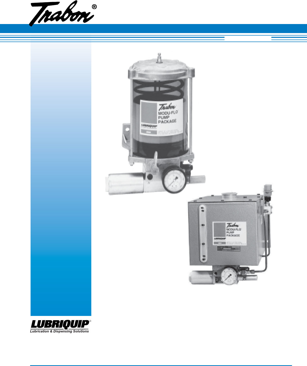
Modular
Pumping
Packages
Revised November 2005
LUBRIQUIP
BY ®
Bulletin 42000
Operation and Service Instructions
Modu-Flo® System
R

42000Modu-Flo® System
R
i
TABLE OF CONTENTS
Section/Para Page
1 INTRODUCTION .............................................. 1-1
1.1 GENERAL ............................................................. 1-1
1.2 GENERAL SYSTEM OPERATION ......................... 1-2
Section/Para Page
5.3 OIL TANK AND RESERVOIR 15 AMP
LOW-LEVEL ASSEMBLY MAINTENANCE
(OPTIONS L1, L2 and L3) .................................... 5-2
5.4 OIL TANK RESERVOIR 10-WATT LOW-LEVEL
ASSEMBLY MAINTENANCE (OPTIONS L5, L6
AND L7) ................................................................ 5-4
5.5 GREASE RESERVOIR LOW-LEVEL ASSEMBLY
MAINTENANCE (OPTION L4) ............................... 5-5
6 HIGH-PRESSURE AND BLOWOUT
SWITCHES ...................................................... 6-1
6.1 DESCRIPTION...................................................... 6-1
6.2 HIGH-PRESSURE SWITCH ADJUSTMENT ........ 6-2
6.3 MOUNTING INSTRUCTIONS ............................... 6-3
6.4 HIGH-PRESSURE SWITCH MAINTENANCE
(OPTION P1) ......................................................... 6-3
6.5 RESERVOIR BLOWOUT SWITCH MAINTE-
NANCE (OPTIONS P2 and P3) ............................ 6-4
6.6 TANK BLOWOUT SWITCH MAINTENANCE
(OPTION P4) ......................................................... 6-6
7 PNEUMATIC SOLENOID OPTIONS ................ 7-1
8 CONTROLLERS .............................................. 8-1
8.1 DESCRIPTION...................................................... 8-1
8.2 WIRING ................................................................. 8-2
9 SYSTEM OPERATION ..................................... 9-1
9.1 GENERAL ............................................................. 9-1
9.2 SYSTEM INFORMATION ....................................... 9-1
9.3 OPERATING TIPS ................................................. 9-1
9.4 MATERIAL CONSIDERATIONS ............................. 9-2
10 TROUBLESHOOTING ................................... 10-1
10.1 GENERAL ........................................................... 10-1
LIST OF ILLUSTRATIONS
Number Title Page Number Title Page
2 RESERVOIRS AND TANKS ............................. 2-1
2.1 DESCRIPTION...................................................... 2-1
2.2 MOUNTING INSTRUCTIONS ............................... 2-1
2.3 PREPARATION FOR USE ..................................... 2-2
2.4 GREASE RESERVOIR MAINTENANCE
(OPTIONS GP1 THROUGH GP5 AND GM1
THROUGH GM4) .................................................. 2-3
2.5 OIL RESERVOIR MAINTENANCE
(OPTIONS OP1 THROUGH OP4) ........................ 2-7
2.6 OIL TANK MAINTENANCE
(OPTIONS T1, T2 and T3) .................................. 2-11
3 PUMPS............................................................ 3-1
3.1 DESCRIPTION...................................................... 3-1
3.2 PREPARATION FOR USE ..................................... 3-3
3.3 PNEUMATIC PUMP MAINTENANCE
(OPTIONS A1 THROUGH A6) .............................. 3-3
3.4 HYDRAULIC PUMP MAINTENANCE
(OPTIONS H1 AND H3) ........................................ 3-9
3.5 HYDRAULIC PUMP MAINTENANCE
(OPTION H2)....................................................... 3-13
4 MANIFOLDS.................................................... 4-1
4.1 DESCRIPTION...................................................... 4-1
4.2 PREPARATION FOR USE ..................................... 4-1
4.3 MAINTENANCE ..................................................... 4-1
5 LOW-LEVEL SWITCHES ................................ 5-1
5.1 DESCRIPTION...................................................... 5-1
5.2. MOUNTING INSTRUCTIONS ............................... 5-1
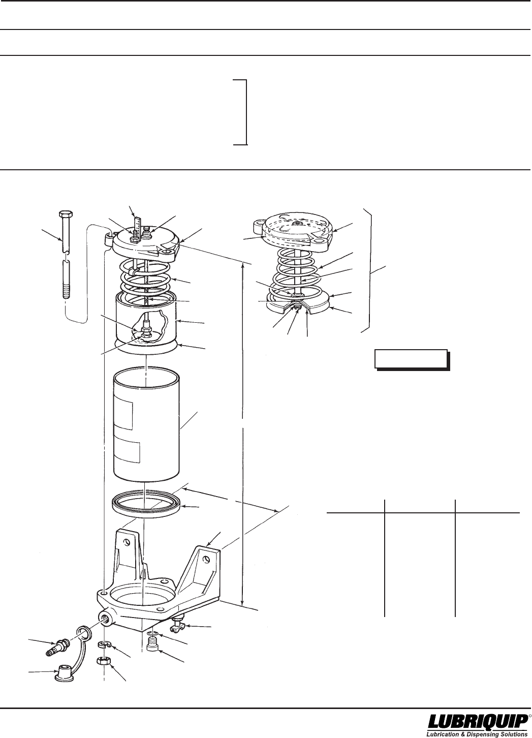
1-1. Modu-Flo Functional Schematic ......................... 1-3
2-1. Grease Reservoir - Exploded View..................... 2-5
2-2. Oil Reservoir - Exploded View ............................ 2-9
2-3. Oil Tank - Exploded View .................................. 2-13
3-1. Typical Pump Operation ...................................... 3-2
3-2. Pneumatic Pump, Exploded View ...................... 3-7
3-3. Hydraulic Pump Options H1 and H3 -
Exploded View ................................................... 3-11
3-4. Hydraulic Pump Option H2 - Exploded View .... 3-15
4-1. Typical Manifold Assembly .................................. 4-3
5-1. Oil Tank and Reservoir 15 Amp Low-Level
Assembly ............................................................ 5-3
5-2. Oil Tank and Reservoir 10-Watt
Low-Level Assembly ........................................... 5-5
5-3. Grease Reservoir Low-Level Assembly ............. 5-6
6-1. High-Pressure Switch ......................................... 6-2
6-2. High-Pressure Switch (Rear View)..................... 6-4
6-3. Reservoir Blowout Switch Assembly (Front
View) .................................................................... 6-5
6-4. Tank Blowout Switch Assembly .......................... 6-7
7-1. Pneumatic Solenoid ........................................... 7-1
8-1. DC Timer Wiring Schematic ............................... 8-2
8-2. AC Timer Wiring Schematic ................................ 8-2
8-3. TC1000 Timer/Counter Wiring Schematic ......... 8-3
8-4. WMP Maxi-Monitor Wiring Schematic ................. 8-3

Modu-Flo® System 42000
R
ii
LIST OF TABLES
Number Title Page
2-1. Reservoirs and Tanks ......................................... 2-2
2-2. Grease Reservoir Parts List ............................... 2-4
2-3. Oil Reservoir Parts Lists ..................................... 2-8
2-4. Oil Tank Parts List ............................................. 2-12
3-1. Pumps................................................................. 3-2
3-2. Pneumatic Pump Parts List ................................ 3-5
3-3. Hydraulic Pump Options H1 and H3
Parts List ........................................................... 3-10
3-4 Hydraulic Pump Option H2 Parts List ............... 3-14
4-1. Operating Ports on Modu-Flo Manifolds ............. 4-2
4-2. Manifolds and Manifold Accessories.................. 4-2
5-1. Low-Level Switch Assemblies ........................... 5-2
5-2. Oil Tank and Reservoir 15 Amp Low-Level
Assemblies Parts List ........................................ 5-3
Number Title Page
5-3. Oil Tank and Reservoir 10-Watt Low-Level
Assemblies Parts List ........................................ 5-5
5-4. Grease Reservoir Low-Level Assembly
Parts List ............................................................. 5-6
6-1. Blowout Discs and Kits....................................... 6-1
6-2. High-Pressure and Blowout Switch
Assemblies ......................................................... 6-2
6-3. Pressure Switch Settings ................................... 6-3
6-4. High-Pressure Switch Parts List ........................ 6-4
6-5. Reservoir Blowout Switch Parts List .................. 6-5
6-6. Tank Blowout Switch Parts List........................... 6-6
7-1. Pneumatic Solenoid Parts List ........................... 7-1
10-1. Modu-Flo Troubleshooting ............................... 10-1

42000Modu-Flo® System
R
OPERATION AND
SERVICE INSTRUCTIONS
Modu–Flo®
System
SECTION 1
INTRODUCTION
1.1 GENERAL................................................................... 1-1
1.1.1 Standard Components................................... 1-1
1.1.2 Modu-Flo Options ........................................... 1-1
1.2 GENERAL SYSTEM OPERATION .............................. 1-1
1.1 GENERAL
1.1.1 Standard Components. A wide choice of modular
components may be assembled to meet a given applica-
tion.
1.1.1.1 All Modu-Flo systems consist of the following
components:
a. A reservoir or tank for holding the lubricant. Reservoirs
are cylindrical units for grease or oil and are equipped
with a spring-loaded follower for grease applications.
Tanks are rectangular and are used for applications
using oil. Further information on reservoirs may be
found in Section 2.
b. A pump for dispensing a specific volume of lubricant.
Pumps may be pneumatically or hydraulically operated.
A selection of power ratios and displacement ranges
are available. Further information on pumps may be
found in Section 3.
c. A manifold attached to the base of the reservoir to
provide a mounting base for any pump. The manifold
has all the necessary porting to allow lubricant to flow
from the reservoir to the pump and from the pump to the
lubricant lines. Ports are also provided for pneumatic or
hydraulic inputs to operate the pump. Accessories such
as gauges and blowout assemblies are available and
may be connected to the manifold. If the pump is to be
located some distance from the reservoir, a wall-
mounted manifold is available. Further information on
manifolds is contained in Section 4.
1.1.2 Modu-Flo Options.
1.1.2.1 Options which are available for any system include
the following:
a. Low-level switches which mount to the reservoir or tank
and provide a low-level fault signal to a customer-
designated component. Level switch options are
described in Section 5.
b. High-pressure indicators which are installed into the
pump outlet circuit and provide an over-pressure signal
to external components. Pressure switch options are
discussed in Section 6.
c. A pneumatic solenoid valve which mounts directly to the
manifold. The solenoid valve is a three-way, normally-
closed type. Use of the solenoid allows the pump to be
cycled by various controller options. The solenoid is
equipped with a manual override button which may be
used to simplify system testing, line filling and line
bleeding.
d. Several types of controllers are used which can be
adapted to the system. Controller options are dis-
cussed in Section 8. Controllers available are as
follows:
(1) Timers which may be set to cycle the pump at given
intervals. Both AC and DC models are available.
(2) A TC-1000 timer can operate the lube system on
either a time or machine cycle basis. It is available
in 12 or 24 VDC or 115 or 230 VAC.
(3) A WMP Maxi-Monitor which provides a dispense
signal on either a time or machine cycle basis. The
WMP also monitors and displays the status of the
lube system it is controlling. The Maxi-Monitor is
available in either 115 or 230 VAC.
1-1

Modu-Flo® System 42000
R
1.2 GENERAL SYSTEM OPERATION
1-2
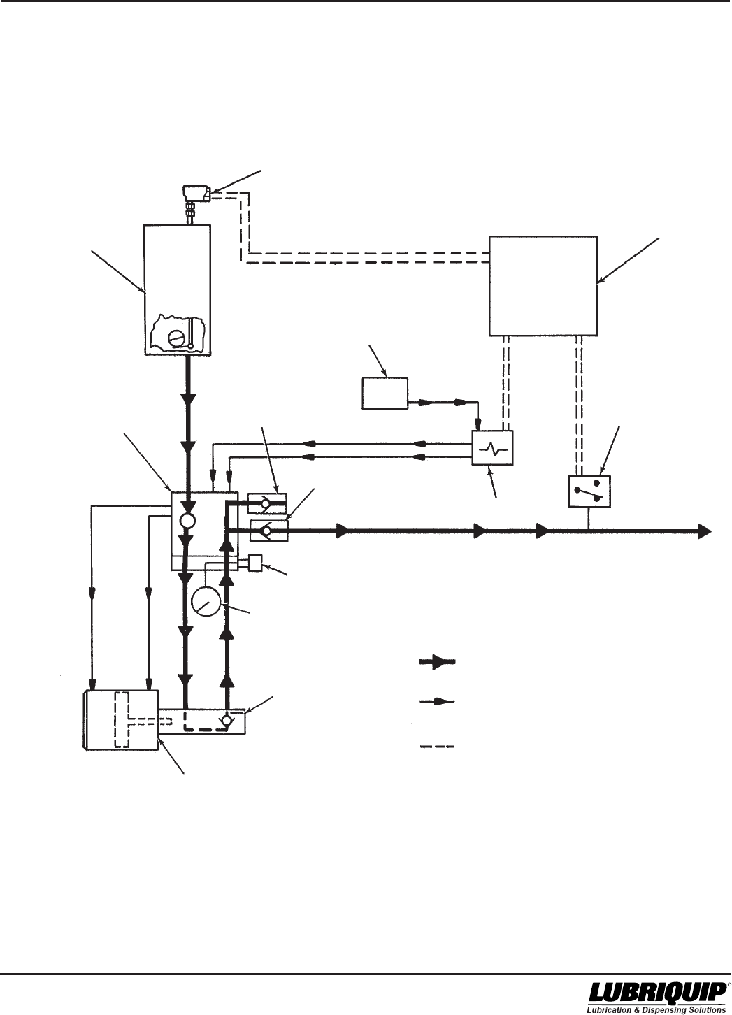
1.2.1 Figure 1-1 shows a functional schematic of a Modu-
Flo system.
1.2.1.1 The following steps outline the operating sequence
of a Modu-Flo system:
a. Lubricant stored in the reservoir or tank flows to the
manifold. The manifold may be mounted directly to the
reservoir or tank, or it may be mounted on a wall.
b. The manifold directs lubricant into the pump to fill the
pump chamber.
c. A controller energizes a solenoid valve to dispense and
the solenoid sends air or hydraulic fluid to the manifold.
Porting in the manifold directs the air or hydraulic fluid to
the pump, causing the pump to dispense lube to the
manifold outlet port.
d. When the controller releases the solenoid, air or
hydraulic fluid is redirected, causing the pump to retract.
On single-acting pneumatic pumps a spring pushes the
pump to the retracted position.
e. Lubricant from the reservoir flows through the manifold
and refills the empty chamber in the pump.
f. A pressure gauge, blowout disc, and high-pressure
switch are options which may be connected to the output
lube on the manifold. A signal from the pressure switch
can be used to actuate an alarm or warning light.
g. Low-level switch options are available for all tanks or
reservoirs. The switch provides an electrical signal
when lubricant level is low.
42000Modu-Flo® System
R
1-3/(1-4 Blank)
LOW LEVEL
SWITCH
CONTROLLER
PRESSURE
SWITCH
SOLENOID
PNEUMATIC/
HYDRAULIC SUPPLY
RESERVOIR
OR TANK
MANIFOLD
LUBE OUTLET
CHECK
SYSTEM FILL
CHECK
BLOWOUT
ASSEMBLY
GAUGE
TEST/AIR
PURGE PORT
PUMP
LUBE LINES
PNEUMATIC/HYDRAULIC
LINES
ELECTRICAL LINES
Figure 1-1. Modu-Flo Functional Schematic

42000Modu-Flo® System
R
OPERATION AND
SERVICE INSTRUCTIONS
Modu–Flo®
System
2-1
SECTION 2
RESERVOIRS AND TANKS
2.1 DESCRIPTION .......................................................... 2-1
2.1.1 Reservoir Description ................................... 2-1
2.1.2 Tank Description ........................................... 2-1
2.1.3 Reservoirs and Tanks Available ................... 2-1
2.2 MOUNTING INSTRUCTIONS ................................... 2-1
2.3 PREPARATION FOR USE ......................................... 2-2
2.3.1 Filling Oil Reservoirs and Tanks ................... 2-2
2.3.2 Filling Grease Reservoirs ............................. 2-2
2.4 GREASE RESERVOIR MAINTENANCE
(OPTIONS GP1 THROUGH GP5 AND GM1 THROUGH
GM4) .......................................................................... 2-3
2.4.1 General .......................................................... 2-3
2.4.2 Grease Reservoir Maintenance .................... 2-3
2.4.3 Disassembly of Grease Reservoirs ............. 2-3
2.4.4 Assembly of Grease Reservoirs ................... 2-3
2.4.5 Grease Reservoir Parts Lists ....................... 2-3
2.1 DESCRIPTION designated by the entry in the ordering code as shown
below:
MPP - XXX - XXX - XX - XX - XX - XX - XX - XXX - XX
Reservoir Option
2.2 MOUNTING INSTRUCTIONS
2.2.1 Reservoirs and tanks may be mounted to any
vertical surface. All units have 7/16 inch holes for attaching
bolts or screws. Cylindrical reservoirs have two holes, six
inches apart, drilled in the base bracket. All tanks have four
holes drilled in flanges according to the following rectangu-
lar dimensions:
9-7/8 wide by 7 inches high for T1 tanks
11-1/8 wide by 7 inches high for T2 tanks
16-3/8 wide by 7 inches high for T3 tanks
2.2.1.1 Make sure the mounting location allows clearance
for any accessories attached to the tank or reservoir. Oil
reservoirs and all tanks have a fill cup on the top. Make sure
there is enough room above the fill cup to permit personnel
to perform a filling operation without difficulty. Drill the re-
quired holes and attach the reservoir or tank to the vertical
surface. Securely tighten all attaching hardware. Make sure
that the reservoir or tank is level.
2.6 OIL TANK MAINTENANCE
(OPTIONS T1, T2 and T3) ....................................... 2-11
2.6.1 General ........................................................ 2-11
2.6.2 Oil Tank Maintenance .................................. 2-11
2.6.3 Disassembly of Oil Tanks ........................... 2-11
2.6.4 Assembly of Oil Tanks................................. 2-11
2.6.5 Oil Tank Parts List ....................................... 2-11
2.5 OIL RESERVOIR MAINTENANCE
(OPTIONS OP1 THROUGH OP4) ............................. 2-7
2.5.1 General .......................................................... 2-7
2.5.2 Oil Reservoir Maintenance ............................ 2-7
2.5.3 Disassembly of Oil Reservoir ....................... 2-7
2.5.4 Assembly of Oil Reservoir ............................. 2-7
2.5.5 Oil Reservoir Parts Lists ............................... 2-7
2.1.2 Tank Description. Tanks are rectangular
weldments used for holding oil. All tanks are equipped with
a sight glass to allow personnel to easily check the lubricant
level. A pad mounted to the tank base provides the neces-
sary tapped holes for either direct mounting of a manifold or
for installing hose or tubing to a remote-located manifold.
2.1.3 Reservoirs and Tanks Available. Table 2-1 lists the
tanks and reservoirs available for use. Listings in the option
column are used to identify the reservoir or tank selected
when a Modu-Flo system is ordered. The option used is
2.1.1 Reservoir Description. Reservoirs are cylindrical in
shape and are used for either grease or oil lubricants. If a
reservoir is to be used for grease it will be equipped with a
spring-loaded follower which will apply pressure on the
grease to force it into the pump. Reservoirs use cylinders
made of metal or plastic. If a metal cylinder is used, the
reservoir will be equipped with a level indicator to allow a
visual check of lubricant level. Plastic cylinders are clear,
allowing personnel to actually see the amount of lubricant
present. The base of all reservoirs has the necessary
tapped holes for either direct mounting of a manifold or for
installing hose or tubing to a remote-located manifold.
Modu-Flo® System 42000
R
2-2
the reservoir without being disconnected. Operate the supply
source at a steady speed to allow air-free filling of the reser-
voir. Too fast of a fill speed may result in air pockets. The
level of grease is checked by visual means. In reservoirs
with plastic cylinders, the grease level may be seen through
the cylinder. Reservoirs with metal cylinders have a level-
indicator rod mounted on the cap which will indicate when
the fill is complete.
NOTE
Excess lube forced into the reservoir after it has
reached full level will be vented from a bleed
hole in the reservoir tube. (See Warning above.)
2.3.2.2 When filling is complete, turn off the supply source
and disconnect it from the fill stud. A check valve in the fill stud
will prevent lubricant from being forced back out. A plastic dust
cap is attached to the fill stud and should be installed over the
fill stud to keep dirt from entering the system.
NOTE
For first time grease filling, or if the grease res-
ervoir has been allowed to go empty, open the
petcock in the bottom right side of the reservoir.
Slowly begin to fill the reservoir, allowing air
trapped under follower to exhaust out the open
petcock. When grease free of air flows from the
petcock, close petcock and continue to fill the
reservoir until follower is at vent hole in reservoir
tube (any remaining air and small amount of
grease will exit vent).
Loosen system mainline connection at pump
outlet. Operate pump until lubricant free of air
flows from outlet port. Tighten mainline connec-
tion at pump. Pump is now free of air.
Note, for extreme cases where the pump will not
take a prime, it may be helpful to inject serveral
2.3 PREPARATION FOR USE
NOTE
Before filling any reservoir or tank, a manifold
should be attached to the base. The manifold
has a check valve built into it which will prevent
the lubricant from dripping out of the reservoir or
tank. If the system has a remote-located mani-
fold, make sure there is hose or tubing con-
nected from the bottom of the reservoir or tank to
the remote manifold.
2.3.1 Filling Oil Reservoirs and Tanks. Reservoirs and
tanks for oil have a fill cup mounted on top. Wipe the area
around the fill cup to avoid contamination during filling. Open
the fill cup cap and slowly pour the oil into the fill cup. A
strainer attached to the fill cup will remove large particles
which may be present in the oil. When filling is complete,
close fillcup cap and wipe any spillage.
2.3.2 Filling Grease Reservoirs.
WARNING
If a high-pressure, high-volume supply pump is
used to fill grease reservoirs, excess pressure
may not be completely released by the bleed
hole in the reservoir wall. This could cause the
reservoir to fracture, exposing personnel to flying
particles and lubricant. Safety glasses must be
worn during filling operations and the supply
pump must be turned off and disconnected
when filling is complete.
2.3.2.1 Filling of grease reservoirs requires that an external
supply source be connected to the fill stud located in the
base of the reservoir. To avoid introducing air into the system,
make sure there is enough grease in the supply source to fill
Table 2-1. Reservoirs and Tanks
Part Number Type (Use) Reservoir Capacity Option
521-001-060 Tank (oil) 12 pint (5.68 liters) T1
521-001-070 Tank (oil) 24 pint (11.4 liters) T2
521-001-080 Tank (oil) 40 pint (18.9 liters) T3
185-100-080 Reservoir, Plastic (oil) 5 pint (2.37 liters) OP1
185-100-060 Reservoir, Plastic (oil) 12 pint (5.68 liters) OP2
185-100-070 Reservoir, Plastic (oil) 20 pint (9.46 liters) OP3
185-100-750 Reservoir, Plastic (oil) 6 pint (2.84 liters) OP4
185-100-040 Reservoir, Plastic (grease) 5 lbs (2.27 kg) GP1
185-100-000 Reservoir, Plastic (grease) 12 lbs (5.44 kg) GP2
185-100-010 Reservoir, Plastic (grease) 20 lbs (9.07 kg) GP3
185-100-760 Reservoir, Plastic (grease) 6 lbs (2.72 kg) GP4
185-101-080 Reservoir, Plastic (grease) 3 lbs (1.36 kg) GP5
185-100-050 Reservoir, Metal (grease) 5 lbs (2.27 kg) GM1
185-100-020 Reservoir, Metal (grease) 12 lbs (5.44 kg) GM2
185-100-030 Reservoir, Metal (grease) 20 lbs (9.07 kg) GM3
185-100-770 Reservoir, Metal (grease) 6 lbs (2.72 kg) GM4
185-101-100 Reservoir, Plastic (grease) 40 lbs (18.14 kg) --
185-101-110 Reservoir, Plastic (grease) w/low level indicator 40 lbs (18.14 kg) --
185-100-120 Reservoir, Plastic (grease) w/low level micro switch 40 lbs (18.14 kg) --
* These assemblies are not available through the normal MPP system, only by ordering the full part number.
*
*
*
42000Modu-Flo® System
R
2-3
ounces of heavy oil through the grease fill quick
disconnect. The pump will then prime on oil
pulling the grease behind it. If it becomes nec-
essary to use this method, all injected oil should
be discharged at the loosened system supply
connection along with any air.
Refer to bulletin 12411 (Portable Filler-Pak) for
manual operated fill pump.
the chance of spillage. The disassembly procedure is as
follows:
2.4 GREASE RESERVOIR MAINTENANCE
(OPTIONS GP1 THROUGH GP5 AND
GM1 THROUGH GM4)
2.4.1 General. Maintenance tips, disassembly, and as-
sembly procedures for grease reservoirs are discussed in
Paragraphs 2.4.2, 2.4.3 and 2.4.4. An exploded view of a
typical grease reservoir is shown in Figure 2-1 and should
be referred to during the discussion.
2.4.2 Grease Reservoir Maintenance.
2.4.2.1 Maintenance on the grease reservoir consists of the
steps described below:
a. Visually inspect the reservoir for lubricant leaking
between reservoir tube (8, Figure 2-1) and base (10).
This may indicate a bad gasket (9) or that the hex nuts
(12) are not tight. Torque the nuts to 5 ft lbs. If the
leakage continues, replace gasket (9). Check for cracks
and nicks in tube (8). Replace the tube as required.
b. Visually inspect the reservoir tube (8) for dents which
may restrict the movement of the follower cups (6 and 7).
Replace the tube as required.
WARNING
Disconnect and lock out power before opening
electrical enclosures or conduit connections.
Serious injury may result from electrical shock.
2.4.3 Disassembly of Grease Reservoirs. Figure 2-1
shows a typical grease reservoir but does not include other
Modu-Flo components which may be mounted to the reser-
voir. These components include the manifold, pump, level
switches and high-pressure blowout switches. Disassembly
of the reservoir may require that some of these components
be removed. The manifold and pump do not normally require
removal, but may be removed if desired. The level and blow-
out switches may or may not require removal, depending on
the level of disassembly required. The electrical connections
to the switches probably should be disconnected in order to
remove various parts without restriction of movement by the
electrical cord. The removal of these components is ex-
plained in other sections of the manual. Refer to the table of
contents to find where the components are discussed.
2.4.3.1 The disassembly procedure may be performed with
the reservoir mounted to the mounting surface. However,
some mounting locations may be too restrictive to provide
access to all components. If your particular installation re-
quires dismounting of the reservoir, make sure the reservoir
is drained of lubricant before removing the attaching hard-
ware. This will reduce the weight of the reservoir and reduce
Do not attempt to remove retaining ring (2) or
cable assembly (5) (Figure 2-1) (or retaining
ring (25) or guide rod (5) for Option GP5). Injury
could result from sudden expansion of spring
(4).
WARNING
a. Slowly open petcock (11) and allow lubricant to be forced
from the reservoir into a bucket or similar container.
Remove fill stud (15) and petcock (11) if necessary.
Properly dispose of emptied grease.
b. Remove hex nuts (12) and lockwashers (13) from tie
rods (1). Remove tie rods (1) from cap (3).
c. Lift reservoir tube (8) from base (10) keeping reservoir
cap (3) in position on top of the tube.
d. Slide reservoir tube (8) away from reservoir cap (3) until
it is free of follower cup (7).
e. Remove gasket (9) from bottom of reservoir tube (8).
f. Further disassembly is only possible at the factory. If
damage is apparent on the follower cups (6 and 7),
cable assembly or guide rod (5), spring (4) or reservoir
cap (3) the unit cannot be serviced and the reservoir
assembly must be replaced.
2.4.4 Assembly of Grease Reservoirs.
NOTE
Before assembly, lubricate followers and tube
inner diameter with the lubricant which is used
in the system.
2.4.4.1 Assemble the grease reservoir according to the
following procedure:
a. Slide reservoir tube (8, Figure 2-1) over follower cup (7)
being careful not to distort the follower cup lips. Slide
reservoir tube (8) up until it contacts reservoir cap (3).
b. Install new gasket (9) on bottom of reservoir tube (8).
c. Place reservoir tube (8) with gasket (9) on base (10) and
rotate reservoir cap (3) until holes in the cap line up with
holes in the base (10).
d. Install tie rods (1) through holes in reservoir cap (3) and
base (10).
e. Install lockwashers (13) and hex nuts (12) on tie rods (1)
and torque to 5 ft lbs.
f. Install fill stud (15), dust cap (14) and petcock (11) in
base. Make sure petcock (11) is in the closed position.
2.4.4.2 When the assembly steps listed in the above para-
graph have been completed, any Modu-Flo components
which were removed to ease disassembly should be rein-
stalled on the reservoir.
2.4.5 Grease Reservoir Parts Lists. Table 2-2 identifies
the parts indexed in Figure 2-1.

Modu-Flo® System 42000
R
2-4
Table 2-2. Grease Reservoir Parts List
Item
Number Part Number Description Quantity
185-100-040 RESERVOIR ASSEMBLY, 5 lbs (2.27 kg), plastic (GP1) --
185-100-000 RESERVOIR ASSEMBLY, 12 lbs (5.44 kg), plastic (GP2) --
185-100-010 RESERVOIR ASSEMBLY, 20 lbs (9.07 kg), plastic (GP3) --
185-100-760 RESERVOIR ASSEMBLY, 6 lbs (2.72 kg), plastic (GP4) --
185-101-080 RESERVOIR ASSEMBLY, 3 lbs (1.36 kg), plastic (GP5) --
185-100-050 RESERVOIR ASSEMBLY, 5 lbs (2.27 kg), metal (GM1) --
185-100-020 RESERVOIR ASSEMBLY, 12 lbs (5.44 kg), metal (GM2) --
185-100-030 RESERVOIR ASSEMBLY, 20 lbs (9.07 kg), metal (GM3) --
185-100-770 RESERVOIR ASSEMBLY, 6 lbs (2.72 kg), metal (GM4) --
1 415-700-272 BOLT, Tie (5 lb., 12 lb.) 3
415-700-271 BOLT, Tie (20 lb.) 3
415-700-273 BOLT, Tie (6 lb.) 3
415-020-190 BOLT, Tie (3 lb.) 3
2 RING, Retaining 1
3 CAP, Reservoir 1
4 SPRING 1
5 CABLE ASSEMBLY 1
GUIDE ROD 1
6 GUIDE, Follower 1
7 CUP Seal 1
9 501-423-001 GASKET (6” Tube) (3,6,12, 20 lb.) 1
501-414-000 GASKET (4” Tube) (5 lb.) 1
10 521-000-500 BASE, Aluminum (6” Tube) (6, 12, 20 lb.) 1
521-000-530 BASE (4” Tube) (5 lb.) 1
521-008-950 BASE, Black (6” Tube) (3 lb.) 1
11 501-970-000 PETCOCK 1
12 410-040-020 NUT, Hex, 5/16-18 3
13 421-010-020 LOCKWASHER, 5/16 inch 3
14 506-165-000 CAP, Dust 1
15 506-189-001 Reservoir Fill Stud 1
16 410-060-120 NUT, Hex, 5/16-18 1
17 511-041-000 PLATE, Backup 1
18 521-003-630 INDICATOR, Level (12 lb. Metal) 1
521-003-640 INDICATOR, Level (20 lb. Metal) 1
521-004-310 INDICATOR, Level (6 lb. Metal) 1
521-003-620 INDICATOR, Level (5 lb. Metal) 1
19 185-100-720+ TUBE, Reservoir, plastic, 13 inches (330.2mm) x 1
4 inches (100 mm) outer diameter (5 lb.)
185-100-730+ TUBE, Reservoir, plastic, 13 inches (330.2 mm) 1
x 6.0 inches (152.4 mm) outer diameter (12 lb.)
185-100-740+ TUBE, Reservoir, plastic, 20 inches (508 mm) x 6.0 1
inches (152.4 mm) outer diameter (20 lb.)
185-100-990+ TUBE, Reservoir, plastic, 8.5 inches (215.9 mm) x 6.0 1
inches (152.4 mm) outer diameter (6 lb.)
185-100-191+ TUBE, Reservoir, plastic, 5 inches (127 mm) x 6.0 1
inches (152.4 mm) outer diameter (3 lb.)
185-101-187+ TUBE, Reservoir, metal, 13 inches (330.2 mm) x 1
4 inches (100 mm) outer diameter (5 lb.)
185-101-188+ TUBE, Reservoir, metal, 13 inches (330.2 mm) x 6.0 1
inches (152.4 mm) outer diameter (12 lb.)
185-101-189+ TUBE, Reservoir, metal, 20 inches (508 mm) x 6.0 1
inches (152.4 mm) outer diameter (20 lb.)
185-101-190+ TUBE, Reservoir, metal, 8.5 inches (215.9 mm) x 6.0 1
inches (152.4 mm) outer diameter ( 6 lb.)
Items 2 through 7
are not serviceable
by the user; replace
entire reservoir.
Mating fill coupler 506-322-000 (order separately)
+ Reservoir Tube Kit includes gasket (item 9).
*
*
42000Modu-Flo® System
R
2-5/(2-6 Blank)
Table 2-2. Grease Reservoir Parts List - Continued
Item
Number Part Number Description Quantity
20 439-060-181 GASKET, Top Vent (3 lb.) 1
21 BUSHING, Follower 1
22 WASHER, Follower 1
23 WASHER, Support 1
24 NUT, Jam, 3/4-16 1
25 O-RING 1
26 RING, Retaining 1
27 527-000-230 PLUG, Low Level (3 lb.) 1
28 527-000-240 GASKET (3 lb.) 1
NOTE:
USED ON METAL
RESERVOIRS ONLY
FOR
OPTION
GP5
ONLY
3
4
5
22
7
23
26
21
25
24
20
2
3
4
5
6
7
8B
16
17
1
18
A
9
10
11
28
27
13
12
15*
14
DIMENSIONS
OPTION A B
GP1, GM1, 7.25 inches 15 inches
GP2, GM2 (184 mm) (381 mm)
GP3, GM3 7.25 inches 22 inches
(184 mm) (559 mm)
GP4, GM4 7.25 inches 10.5 inches
(184 mm) (267 mm)
GP5 7.25 inches 6.87 inches
(184 mm) (174 mm)
19+
Figure 2-1. Grease Reservoir - Exploded View
Do not attempt to remove retain-
ing ring (2) or cable assembly (5),
(Figure 2-1) (or retaining ring (26)
or guide rod (5) for Option GP5).
Injury could result from sudden
expansion of spring (4).
WARNING
Items 21 through 26
are not serviceable
by the user; replace
entire reservoir.
* Mating fill coupler 506-322-000 (order separately)
+ Reservoir Tube Kit includes gasket (item 9).
42000Modu-Flo® System
R
2-7
2.5 OIL RESERVOIR MAINTENANCE
(OPTIONS OP1 THROUGH OP4)
2.5.1 General. Maintenance tips, disassembly, and as-
sembly procedures for oil reservoirs are discussed in Para-
graphs 2.5.2, 2.5.3 and 2.5.4. An exploded view of a typical oil
reservoir is shown in Figure 2-2 and should be referred to
during the discussion.
2.5.2 Oil Reservoir Maintenance.
2.5.2.1 Maintenance on the oil reservoir consists of the
following:
a. Visually check for oil leakage between reservoir tube (6,
Figure 2-2) and base (8). Leakage may indicate that the
gasket (7) is defective or that nuts (9) are not tight.
Torque nuts (9) to 5 ft lbs. If leakage continues, replace
gasket (7). Check for cracks and nicks on tube (6).
Replace the tube as required.
b. Visually check screen (2) in fill cup (3) to make sure it is
not clogged. If necessary, remove the screen for clean-
ing.
c. Check reservoir bottom for debris. Clean as required.
WARNING
Disconnect and lock out power before opening
electrical enclosures or conduit connections.
Serious injury may result from electrical shock.
2.5.3 Disassembly of Oil Reservoir. Figure 2-2 shows a
typical oil reservoir but does not include other Modu-Flo
components which may be mounted to the reservoir. These
components include the manifold, pump, level switches and
high-pressure blowout switches. Disassembly of the reser-
voir may require that some of these components be re-
moved. The manifold and pump do not normally require
removal, but may be removed if desired. The level and blow-
out switches may or may not require removal, depending on
the level of disassembly required. The electrical connections
to the switches should be disconnected in order to remove
various parts without restriction of movement by the electrical
cord. The removal of these components is explained in other
sections of the manual. Refer to the table of contents to find
where the components are discussed.
2.5.3.1 The disassembly procedure may be performed with
the reservoir mounted to the mounting surface. However,
some mounting locations may be too restrictive to provide
access to all components. If your particular installation re-
quires dismounting of the reservoir, make sure the reservoir
is drained of lubricant before removing the attaching hard-
ware. This will reduce the weight of the reservoir and reduce
the chance of spillage. The disassembly procedure is as
follows:
a. Remove pipe plug (4, Figure 2-2) from base (8) and
allow oil to drain from reservoir into bucket or similar
container. Properly dispose of emptied oil.
b. Remove three hex nuts (9) and three lockwashers (10)
from tie rods (1). Remove tie rods (1) from reservoir cap
(5).
c. Remove reservoir cap (5) from reservoir tube (6).
d. Remove fill screen (2) from fill cup (3) and clean screen.
e. Remove reservoir tube (6) from base (8).
f. Remove and discard gasket (7) from reservoir tube (6).
2.5.4 Assembly of Oil Reservoir.
NOTE
Before assembly, lubricate followers and tube
inner diameter with the lubricant which is used
in the system.
2.5.4.1 Assemble the oil reservoir according to the follow-
ing procedure:
a. Install screen (2, Figure 2-2) in fill cup (3).
b. Install new gasket (7) on reservoir tube (6).
c. Position reservoir tube (6) on base (8) and position
reservoir cap (5) on tube.
d. Rotate reservoir cap (5) until tie rods (1) can be installed
through holes in cap and in base (8). The heads of tie
rods (1) must fit into the hexagon depressions on the
upper surface of the reservoir cap (5).
e. Install lockwashers (10) and hex nuts (9) on tie rods (1).
Torque nuts to 5 ft lbs.
f. Install pipe plug (4) in base (8).
2.5.4.2 When the assembly steps listed in the above para-
graph have been completed, any Modu-Flo components
which were removed to ease disassembly should be rein-
stalled on the reservoir.
2.5.5 Oil Reservoir Parts Lists. Table 2-3 identifies the
parts indexed in Figure 2-2.

Modu-Flo® System 42000
R
2-8
Table 2-3. Oil Reservoir Parts Lists
Item
Number Part Number Description Quantity
185-100-080 RESERVOIR ASSEMBLY, 5 pint (2.37 liters), plastic (OP1) --
185-100-060 RESERVOIR ASSEMBLY, 12 pint (5.68 liters), plastic (OP2) --
185-100-070 RESERVOIR ASSEMBLY, 20 pint (9.46 liters), plastic (OP3) --
185-100-750 RESERVOIR ASSEMBLY, 6 pint (2.84 liters), plastic (OP4) --
1 415-700-272 BOLT, Tie (5 pint, 12 pint) 3
415-700-273 BOLT, Tie (6 pint) 3
415-700-271 BOLT, Tie (20 pint) 3
2 534-304-003 SCREEN (40 Mesh) 1
3 534-147-000 CUP, Fill 1
4 508-975-000 PLUG, Pipe, 1/4 inch NPT 3
5 521-000-600 CAP, Reservoir (4” Tube) (5 pint) 1
501-474-029 CAP, Reservoir (6” Tube) (6,12, 20 pint) 1
6 185-100-720+ TUBE, Reservoir, 13 inches (330.2 mm) x 4 inches1
(100 mm) outer diameter (5 pint)
185-100-990+ TUBE, Reservoir, 8.5 inches (215.9 mm) x 6.0 inches 1
(152.4 mm) outer diameter (6 pint)
185-100-730+ TUBE, Reservoir, 13 inches (330.2 mm) x 6.0 inches 1
(152.4 mm) outer diameter (12 pint)
185-100-740+ TUBE, Reservoir, 20 inches (508 mm) x 6.0 inches1
(152.4 mm) outer diameter (20 pint)
7 501-414-000 GASKET (4” Tube) (5 pint) 1
501-423-001 GASKET (6” Tube) (6, 12, 20 pint) 1
8 521-000-530 BASE (4” Tube) (5 pint) 1
521-000-500 BASE (6” Tube) (6, 12, 20 pint) 1
9 410-040-020 NUT, Hexagon, 5/16-18 3
10 421-010-020 LOCKWASHER, 5/16 inch 3
+ Reservoir Tube Kit includes gasket (Item 7).
42000Modu-Flo® System
R
2-9/(2-10 Blank)
Figure 2-2. Oil Reservoir - Exploded View
2
1
3
4
6+
B
5
7
A
8
4
10
9
4
DIMENSIONS
OPTION A B
OP1, OP2 7.25 inches 15 inches
(184 mm) (381 mm)
OP3 7.25 inches 22 inches
(184 mm) (559 mm)
OP4 7.25 inches 10.5 inches
(184 mm) (267 mm)
+ Reservoir Tube Kit includes gasket (Item 7).

42000Modu-Flo® System
R
2-11
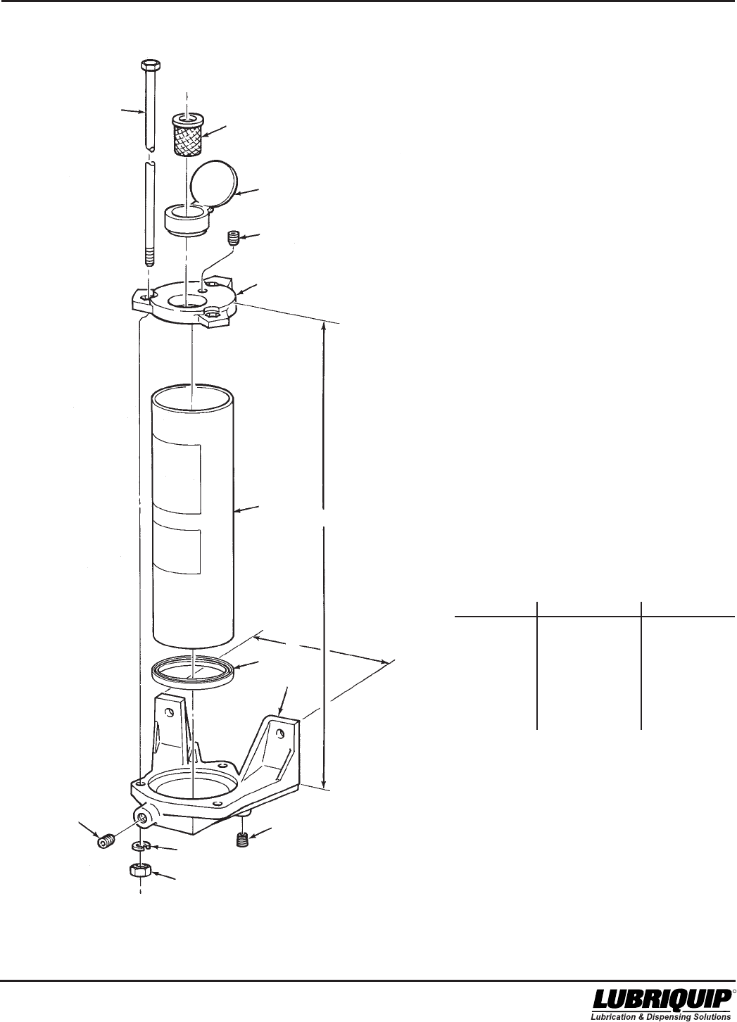
2.6 OIL TANK MAINTENANCE
(OPTIONS T1, T2 and T3)
2.6.1 General. Maintenance tips, disassembly and as-
sembly procedures for oil tanks are discussed in Para-
graphs 2.6.2, 2.6.3 and 2.6.4. An exploded view of a typical oil
tank is shown in Figure 2-3 and should be referred to during
the discussion.
2.6.2 Oil Tank Maintenance.
2.6.2.1 Maintenance on the oil tanks consists of the follow-
ing:
a. Visually check for oil leakage between the tank (9, Figure
2-3), the pump mounting pad (12) and the level sight
glass (11). Leakage in either of these areas indicates
the components are loose or that gasket (10) or o-ring
(13) is defective. The cover (1) will need to be removed
to either tighten the components or replace defective
seals.
b. Visually check fill screen (4) to make sure it is not
clogged. If necessary, remove the screen for cleaning.
c. Check that the tank is securely fastened to the wall or
supporting structures. Securely tighten any loose
attaching hardware.
WARNING
Disconnect and lock out power before opening
electrical enclosures or conduit connections.
Serious injury may result from electrical shock.
2.6.3 Disassembly of Oil Tanks. Figure 2-3 shows a
typical oil tank but does not include other Modu-Flo compo-
nents which may be mounted to the tank. These compo-
nents include the manifold, pump, level switches and blow-
out switches. Disassembly of tank may require that some of
these components be removed. The manifold and pump do
not normally require removal, but may be removed if desired.
The level and blowout switches may or may not require
removal, depending on the level of disassembly required.
The electrical connections to the switches should be discon-
nected in order to remove various parts without restriction of
movement by the electrical cord. The removal of these com-
ponents is explained in other sections of the manual. Refer
to the table of contents to find where these components are
discussed.
2.6.3.1 The disassembly procedure may be performed with
the tank mounted to the mounting surface. However, some
mounting locations may be too restrictive to provide access
to all components. If your particular installation requires
dismounting of the tank, make sure the tank is drained of
lubricant before removing the attaching hardware. This will
reduce the weight of the tank and reduce the chance of spill-
age. The disassembly procedure is as follows:
a. Remove pipe plug (3, Figure 2-3) from base of tank
weldment (9) and allow oil to drain into bucket or similar
container. Properly dispose of emptied oil.
b. Remove self-threading screws (2) attaching cover (1) to
tank weldment (9) and remove cover and cover gasket
(6).
c. Remove fill screen (4) from fill cup (5) and clean screen.
d. Remove two screws (7) and aluminum gaskets (8) to
release pump mounting pad (12) from tank weldment
(9). Remove and discard o-ring (13) from pump mount-
ing pad (12).
2.6.4.2 When the assembly steps listed in the above para-
graph have been completed, any Modu-Flo components
which were removed to ease disassembly should be rein-
stalled on the tank.
2.6.5 Oil Tank Parts List. Table 2-4 identifies the parts
indexed in Figure 2-3.
NOTE
Step e should be performed only if the sight
glass is dirty or leaking. Threads cut on nylon
studs of sight glass may prevent the sight glass
from being used.
e. Remove four self-threading nuts (14) and remove sight
glass (11) and gasket (10). Discard gasket (10) and
sight glass (11).
2.6.4 Assembly of Oil Tanks.
NOTE
Before assembly, lubricate all o-rings with the
lubricant which is used in the system.
2.6.4.1 Assemble the oil tanks according to the following
procedure:
a. Install one aluminum gasket (8, Figure 2-3) on each
screw (7) and insert threads of screws through holes in
bottom of tank weldment (9).
b. Install new o-ring (13) in pump mounting pad (12) and
align threaded holes in pump mounting pad with screws
(7) protruding from bottom of tank weldment (9). Thread
screws (7) into pump mounting pad (12) until pump
mounting pad is snug against bottom of tank weldment
(9). Torque screws (7) to 10 ft lbs.
c. Position new gasket (10) on sight glass (11) and install
sight glass on tank weldment (9). Secure sight glass
(11) with four self-threading nuts (14).
d. Install screen (4) into fill cup (5).
e. Position cover gasket (6) and cover (1) on tank
weldment (9) and secure with self-threading screws (2).
f. Install pipe plug (3) in bottom of tank weldment (9).

Modu-Flo® System 42000
R
2-12
Table 2-4. Oil Tank Parts List
Item
Number Part Number Description Quantity
521-001-060 RESERVOIR ASSEMBLY, 12 pint, (5.68 liters) (T1) --
521-001-070 RESERVOIR ASSEMBLY, 24 pint, (11.4 liters) (T2) --
521-001-080 RESERVOIR ASSEMBLY, 40 pint, (18.9 liters) (T3) --
1 521-000-810 COVER, (12 pint) 1
521-000-830 COVER, (24 pint) 1
521-000-850 COVER, (40 pint) 1
2 415-640-040 SCREW, Self-threading, 1/4-28 x 5/16 inch (12 pint) 6
415-640-040 SCREW, Self-threading, 1/4-28 x 5/16 inch (24, 40 pint) 8
3 508-975-000 PLUG, Pipe, 1/4 inch NPT 2
4 534-304-003 SCREEN (40 Mesh) 1
5 534-147-000 CUP, Fill 1
6 521-003-420 GASKET, Cover, (12 pint) 1
521-003-380 GASKET, Cover, (24 pint) 1
521-003-340 GASKET, Cover, (40 pint) 1
7 419-170-010 SCREW, Socket-head, 3/8-16 x 1/2 inch 2
8 439-050-060 GASKET, 3/8 stat-o-seal 2
9 WELDMENT, Reservoir 1
10 439-060-110 GASKET 1
11 438-028-283 SIGHT GLASS 1
12 521-000-921 PAD, Pump mounting 1
13 423-700-096 O-RING 1
14 410-701-986 NUT, Self-threading 4
15 421-010-010 Lockwasher, 1/4 inch (12 pint) 6
421-010-010 Lockwasher, 1/4 inch (24, 40 pint) 8
16 412-150-040+ Plug, 3/8 NPT 1
*Reservoirs with separate aluminum pump mounting pads
only. Steel pump mounting pads are welded in place and
are not replaceable.
+ Used on reservoirs with front pressure-fill port only.
Not available as a
item replacement
*
*
*
*
42000Modu-Flo® System
R
2-13/(2-14 Blank)
3
4
5
7*
8*
9
2
1
14
A
10 11
13*
12*
B
3
C
6
Figure 2-3. Oil Tank - Exploded View
* Reservoirs with separate aluminum
pump mounting pads only. Steel pump
mounting pads are welded in place
and are not replaceable.
+ Used on reservoirs with front pressure-fill
port only.
DIMENSIONS
OPTION A B C
T1 10.75 inches 7.25 inches 10.70 inches
(273 mm) (184 mm) (272 mm)
T2 12 inches 13.22 inches 10.59 inches
(305 mm) (336mm) (269 mm)
T3 17.25 inches 13.22 inches 10.59 inches
(438 mm) (336 mm) (269 mm)
16+
15

42000Modu-Flo® System
R
OPERATION AND
SERVICE INSTRUCTIONS
Modu–Flo®
System
3-1
SECTION 3
PUMPS
3.1 DESCRIPTION .......................................................... 3-1
3.1.1 General .......................................................... 3-1
3.2 PREPARATION FOR USE ......................................... 3-3
3.2.1 Mounting ........................................................ 3-3
3.2.2 Output Adjustment ......................................... 3-3
3.3 PNEUMATIC PUMP MAINTENANCE
(OPTIONS A1 THROUGH A6) ................................... 3-3
3.3.1 General .......................................................... 3-3
3.3.2 Pneumatic Pump Maintenance Tips ............ 3-3
3.3.3 Disassembly of Pneumatic Pump ................ 3-3
3.3.4 Assembly of Pneumatic Pump ..................... 3-4
3.3.5 Pneumatic Pump Parts List .......................... 3-4
3.4 HYDRAULIC PUMP MAINTENANCE
(OPTIONS H1 and H3).............................................. 3-9
3.4.1 General .......................................................... 3-9
3.4.2 Hydraulic Pump Options H1 and H3
Maintenance Tips .......................................... 3-9
3.4.3 Disassembly of Hydraulic Pump
Options H1 and H3 ....................................... 3-9
3.4.4 Assembly of Hydraulic Pump Options H1
and H3 ........................................................... 3-9
3.4.5 Hydraulic Pump Options H1 and H3
Parts List ..................................................... 3-10
3.5 HYDRAULIC PUMP MAINTENANCE
(OPTION H2) ........................................................... 3-13
3.5.1 General ........................................................ 3-13
3.5.2 Hydraulic Pump Option H2
Maintenance Tips ........................................ 3-13
3.5.3 Disassembly of Hydraulic Pump
Option H2 .................................................... 3-13
3.5.4 Assembly of Hydraulic Pump Option H2 .... 3-13
3.5.5 Hydraulic Pump Option H2 Parts List ......... 3-14
3.1 DESCRIPTION
3.1.1 General. There are six models available for use.
Three models are pneumatically operated and three are
hydraulically operated. The pneumatic models may be
single or double acting. An internal spring will return the
piston to the reload position in single-acting pumps. All
hydraulic models are double-acting.
3.1.1.1 All models are designed to mount directly to either
the pump-to-reservoir manifold or the pump-to-wall mani-
fold. When the pump is properly mounted on a manifold, the
manifold will have all the porting for air and lubricant
connections to and from the pump.
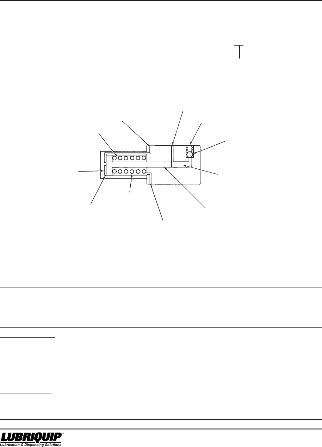
3.1.1.2 Operating sequences for single-acting and double-
acting pumps are listed below. Figure 3-1 shows a sec-
tional view of a typical pump and will help in understanding
pump operation.
a. With single-acting models, air under pressure is
supplied through the inlet port (SA) to chamber (C). This
moves the air and lube pistons to the right. This closes
the lube inlet port and forces the lubricant already in
chamber (B) past the check valve and into the system.
Air in chamber (A) must vent out port (DA). A plastic pipe
plug with a vent hole is installed in port (DA). After a
preset time interval the solenoid valve shuts off the air
supply and vents chamber (C) through port (SA). The
spring returns the air and lube pistons, opening
chamber (B) to the lube reservoir.This completes a
single pump cycle and chamber (B) is primed, ready for
the next cycle.
b. The double-acting models have an additional air or
hydraulic supply line connected to port (DA). When the
pistons have been moved to the right, air or hydraulic
supply to port (SA) is shut off and vented. Then, air or
hydraulic fluid under pressure is supplied to port (DA),
which returns the pistons to their original position. This
more powerful return action allows an increased cycle
rate of the pump.
3.1.1.3 All pneumatic pumps have a lube-to-air pressure
ratio of 30:1. The pumps operate on input pressure ranging
from 40 to 150 psi (3 to 10 bar). The HLJ-5M and HLJ-25M
hydraulic pumps have a lube-to-hydraulic ratio of 5.5:1. The
HLJ-5X has a lube-to-hydraulic ratio of 2.2:1. The hydraulic
pumps operate on input pressures ranging from 200 to
2000 psi (14 to 138 bar). It should be noted that lower input
pressures may prevent the pumps from building sufficient
pressure to crack a rupture disc or activate a high-pressure
device. In pneumatic systems, with an inlet air pressure of
40 psi (3 bar), only 1200 psi (83 bar) could be developed. In
hydraulic systems, with 200 psi (14 bar) only 1100 psi
(76 bar) could be developed. Neither of these pressures
would be high enough to crack a 1450 psi disc. The system
could be blocked and not functioning without giving any
indication to plant personnel. The supply pressure, either
penumatic or hydraulic, should be adjusted high enough to
ensure that a blocked line will cause sufficient pressure to
be developed.
Modu-Flo® System 42000
R
3-2
3.1.1.4 In pneumatically-operated systems, pressure
surges often occur when the solenoid is energized. These
surges can be minimized by installing air flow devices in the
solenoid pneumatic lines.
3.1.1.5 Table 3-1 lists the available pumps along with other
data. Note that the part number on the pneumatic pump is
the same for two different pump models. This is because
any pneumatic pump may be used as either single- or
double-acting. Listings in the option column are used to
identify the pump selected when a Modu-Flo system is
ordered. The option used is designated by the entry in the
ordering code as shown below:
MPP - XXX - XXX - XX - XX - XX - XX - XX - XXX - XX
Pump Option
Figure 3-1. Typical Pump Operation
Table 3-1. Pumps
Input
Volume
Output Maximum Per Full
Part Displacement Range Strokes/ Stroke/Cycle
Number Model Action cu in (cm3) per stroke Minute cu.in. (cm3) Option
A. Pneumatic Pumps
521-000-001 AL-5 Single 0.010 to 0.030 (0.164 to 0.492) 65 1.06 (17.4) A1
Double 100 2.09 (34.3)
521-000-021 AL-25 Single 0.030 to 0.120 (0.492 to 1.966) 25 4.20 (68.8) A3
Double 100 8.28 (135.7)
521-000-041 AL-50 Single 0.060 to 0.240 (0.983 to 3.933) 20 8.40 (137.6) A5
Double 60 16.56 (271.4)
B. Hydraulic Pumps
521-000-011 HLJ-5 Double 0.010 to 0.030 (0.164 to 0.492) 100 0.35 (5.7) H1
521-000-031 HLJ-25 Double 0.030 to 0.120 (0.492 to 1.966) 50 1.38 (22.6) H2
521-005-900 HLJ-5X Double 0.030 to 0.092 (0.492 to 1.51) 100 1.28 (21.0) H3
LUBE INLET
PORT
LUBE OUTLET
PORT
SINGLE ACTING
(S.A.) PORT
CHAMBER (A)
AIR PISTON
RETURN
SPRING
DOUBLE ACTING
(D.A.) PORT
LUBE PISTON
CHAMBER (B)
CHECK
VALVE
CHAMBER (C)

42000Modu-Flo® System
R
3-3
3.2 PREPARATION FOR USE
3.2.1 Mounting. Any pump mounts directly to any manifold
with four socket-head capscrews. Care must be taken to
ensure that the outlet of the manifold is lined up with the inlet
on the pump. The face of the pump which mates with the
manifold has several o-rings. When the pump is being
installed, care must be taken to ensure these o-rings are not
moved out of position. The o-rings provide a seal for the
movement of air and lubricant between the manifold and
pump. If an o-ring is missing, air or lubricant may leak. After
being secured to the manifold, no further connections can be
made to the pump.
3.2.2 Output Adjustment. Adjustment of the pump output
may be made with the pump removed from or still attached
to the manifold.
3.2.2.1 The procedure for output adjustment is listed below.
The items referenced are found in Figure 3-2. The adjust-
ment procedure is the same for both pneumatic and hydrau-
lic pumps.
a. Remove adjustment cap (22) from adjustment screw
(13), holding jam nut (21) if necessary.
b. Butt adjustment cap (22) against jam nut (21) and use
the stamped numbers on the cap to determine how
much adjustment is needed.
c. Loosen jam nut (21) and use a flat screwdriver to turn
adjustment screw (13). Turn adjustment screw in for
less output, turn out for more output.
d. Tighten jam nut (21) and install adjustment cap (22)
over the adjustment screw (13).
3.2.2.2 When adjusting pump output, one complete turn of
the adjusting screw will change the output by the following
amounts:
a. 0.0018 cubic inch for pump options A1 and A2.
b. 0.006 cubic inch for pump options A3 and A4.
c. 0.009 cubic inch for pump options A5 and A6.
d. 0.0018 cubic inch for pump option H1.
e. 0.006 cubic inch for pump option H2 and H3.
3.3 PNEUMATIC PUMP MAINTENANCE
(OPTIONS A1 THROUGH A6)
3.3.1 General. Maintenance tips, disassembly and
assembly procedures for pneumatic pumps are discussed
in Paragraphs 3.3.2 through 3.3.4. An exploded view of a
typical pneumatic pump is shown in Figure 3-2 and should
be referred to during the discussion.
3.3.2 Pneumatic Pump Maintenance Tips.
3.3.2.1 The only maintenance required on the pneumatic
pump is to check for the following:
a. Check four socket-head screws (11, Figure 3-2) to make
sure they are tight. Loose screws could allow air and/or
lubricant to leak between the pump and the manifold.
This condition could result in erratic pump output.
b. Check jam nut (21) to make sure it is tight against
adjustment screw body (19). If the jam nut is loose, the
adjustment screw (13) could rotate and cause the pump
output to change. This condition could also result in
lubricant leakage or in air being sucked into the lubri-
cant.
3.3.2.2 If internal components of the pump are defective it
will usually result in erratic pump operation or output. Section
9 of this manual lists causes and solutions for problems
which could occur in the Modu-Flo system. Before disas-
sembling any pump, refer to Section 10. The problem may
be caused by other conditions which can be checked first
before disassembling the pump.
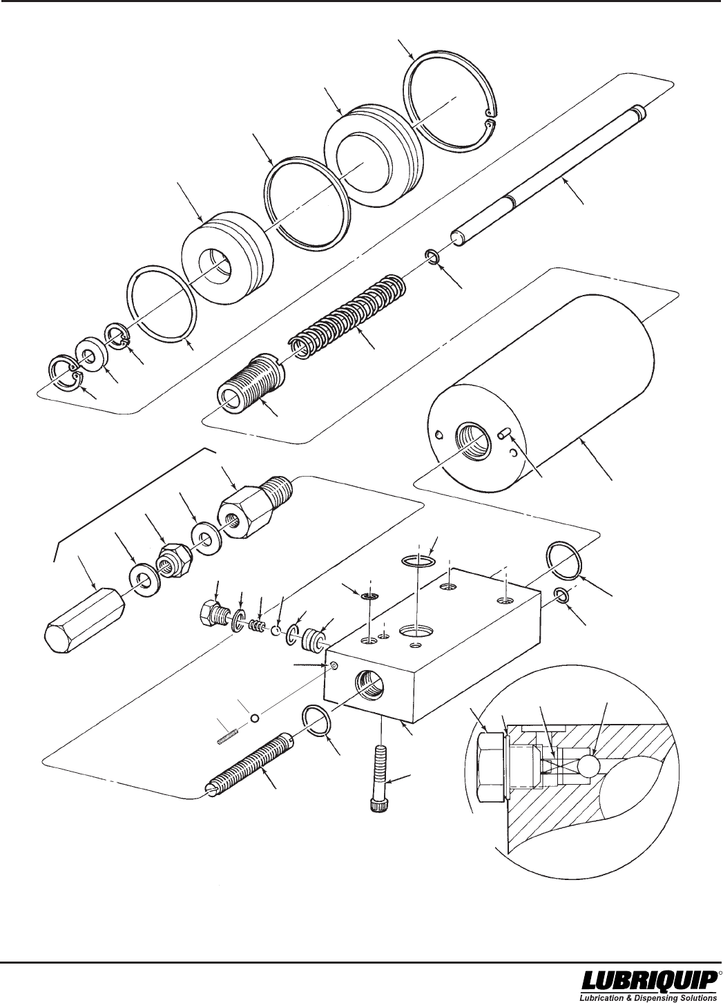
3.3.3 Disassembly of Pneumatic Pump. The procedure
below describes complete disassembly of a pump. How-
ever, you only need to disassemble to your specific area of
concern.
3.3.3.1 The disassembly procedure for the pneumatic
pump is as follows:
NOTE
Figure 3-2 shows air cylinder (7) separated from
pump body (10). To achieve disassembly to this
level requires special tools to remove air cylin-
der retainer (23). Normally, this level of disas-
sembly is only performed at the factory. If scoring
or wear marks are evident on the inner diameter
of air cylinder (7) or pump body (10), the pump
assembly cannot be serviced and should be
replaced.
a. Separate pump from manifold by removing four socket-
head screws (11, Figure 3-2). Remove and discard three
o-rings (9) and one o-ring (18).
b. Remove enclosure screw (14). Remove and discard
gasket (15). Remove check valve spring (16), ball (32),
and check seat (29). Remove and discard o-ring (30)
from seat (29).
c. Remove adjustment screw body (19) and o-ring (12)
from pump body (10). Discard o-ring (12). Removal of
adjustment screw (13) from adjustment screw body (19)
will change output setting when pump is reassembled.
If adjustment screw (13) requires removal, perform the
following:
(1) Remove adjustment screw cap (22) from adjust-
ment screw (13). Butt the adjustment screw cap
(22) against jam nut (21) and use the stamped
numbers on the cap to measure how far the
adjustment screw (13) extends from the jam nut.
Record this dimension.
(2) Remove jam nut (21) and two gaskets (20). Discard
gaskets.
(3) Remove adjustment screw (13) by screwing it
towards the hex portion of the adjustment screw
body (19) until it is free.
d. Remove retainer ring (4).

Modu-Flo® System 42000
R
3-4
e. Insert wooden dowel or soft rod into pump body (10) and
push lube piston (5) until cylinder cap (3) is out of air
cylinder (7). Remove and discard o-ring (2) from cylinder
cap (3).
f. Continue to push lube piston (5) through pump body
(10) until air piston (1) is exposed and can be removed
from air cylinder (7). Remove air piston (1), lube piston
(5), and piston-return spring (24) from air cylinder (7).
g. Remove retainer ring (25) and spring retainer (26) from
air piston (1).
h. Remove retainer ring (27) to separate lube piston (5)
from air piston (1). Remove and discard o-rings (6 and
28).
3.3.4 Assembly of Pneumatic Pump.
3.3.4.1 Assemble the pneumatic pump according to the
following procedure:
NOTE
Use new o-rings, gaskets and return spring
when assembling pump. Lubricate all o-rings
and sliding parts with the lubricant which is
used in the system.
a. Install new o-ring (6) on lube piston (5).
b. Install new o-ring (28) on air piston (1). Install lube
piston (5) into air piston (1) and secure with retainer ring
(27).
c. Install spring retainer (26) in air piston (1) and secure
with retainer ring (25).
d. Install piston-return spring (24) in air cylinder (7). Push
air piston (1) through air cylinder (7) and into pump body
(10).
e. Install new o-ring (2) on cylinder cap (3) and secure in
air cylinder (7) with retainer ring (4).
f. Insert smaller end of adjustment screw (13) into
adjustment screw body (19). Rotate adjustment screw
(13) until smaller end is protruding from hex portion of
adjustment screw body (19).
g. Install new o-ring (12) on adjustment screw body (19)
and install adjustment screw body in pump body (10).
Tighten securely.
h. Install jam nut (21) and two new gaskets (20), one on
each side of jam nut, on adjustment screw (13). Butt
adjustment screw cap (22) against jam nut (21) and turn
adjustment screw (13) until the length it extends beyond
the jam nut is the same as the length recorded during
disassembly.
i. Install adjustment screw cap (22) on adjustment screw
(13).
j. Install new o-ring (30) on check seat (29) and install
seat into pump body.
k Install steel ball (32) and check valve spring (16) into
pump body (10). Place new gasket (15) on enclosure
screw (14). Install enclosure screw (14) into pump body
(10) and tighten securely.
l Install three new o-rings (9) and one new o-ring (18) into
pump body (10). Securely attach to manifold with four
socket-head screws (11).
3.3.4.2 When the assembly steps listed above have been
completed, adjust the pump output as described in Para-
graph 3.2.2.
3.3.5 Pneumatic Pump Parts List. Table 3-2 identifies
the parts indexed in Figure 3-2.

42000Modu-Flo® System
R
3-5
Table 3-2. Pneumatic Pump Parts List
Item
Number Part Number Description Quantity
521-000-001 PUMP ASSEMBLY (AL5) --
521-000-021 PUMP ASSEMBLY (AL25) --
521-000-041 PUMP ASSEMBLY (AL50) --
1 521-000-110 PISTON, Air (AL5) 1
521-000-220 PISTON, Air (AL25) 1
521-000-400 PISTON, Air (AL50) 1
2 422-010-290+ O-RING, Part of kit 560-001-021 (AL5) 1
422-010-350+ O-RING, Part of kit 560-001-031 (AL25) 1
422-010-380+ O-RING, Part of kit 560-001-041 (AL50) 1
3 521-000-100 CAP, Cylinder (AL5) 1
521-000-210 CAP, Cylinder (AL25) 1
521-000-390 CAP, Cylinder (AL50) 1
4 418-050-310+ RING, Retainer, part of kit 560-001-021 (AL5) 1
418-050-450+ RING, Retainer, part of kit 560-001-031 (AL25) 1
418-050-520+ RING, Retainer, part of kit 560-001-041 (AL50) 1
5 PISTON, Lube 1
6 527-000-790+ O-RING, Part of kit 560-001-021 (AL5) 1
423-700-111+ O-RING, Part of kit 560-001-031 (AL25) 1
423-700-112+ O-RING, Part of kit 560-001-041 (AL50) 1
7 521-000-080 CYLINDER, Air (AL5) 1
521-000-200 CYLINDER, Air (AL25) 1
521-000-450 CYLINDER, Air (AL50) 1
8 422-010-200+ O-RING, Part of kits 560-001-021, 560-001-031 and 560-001-041 1
9 423-700-113+ O-RING, Part of kits 560-001-021, 560-001-031 and 560-001-041 5
10 BODY, Pump 1
11 419-130-070+ SCREW, Socket-head, 1/4-20 x 1-1/4 inch 4
12 422-011-140+ O-RING, Part of kits 560-001-021, 560-001-031 and 560-001-041 1
13 521-003-000 SCREW, Adjustment (AL5) 1
521-003-010 SCREW, Adjustment (AL25) 1
521-003-020 SCREW, Adjustment (AL50) 1
14 521-008-460 SCREW, Enclosure 1
15 500-132-000+ GASKET, Part of kits 560-001-021, 560-001-031 and 560-001-041 1
16 511-893-000+ SPRING, Check valve, part of kits 1
560-001-021, 560-001-031 and 560-001-041
17 401-030-030+ BALL, Steel, 3/16 inch diameter, part of kits 1
560-001-021, 560-001-031 and 560-001-041
18 423-700-114+ O-RING, Part of kit 560-001-021, 560-001-031, 560-001-041 1
19 521-003-030 BODY, Adjustment screw (AL5) 1
521-003-040 BODY, Adjustment screw (AL25) 1
521-003-050 BODY, Adjustment screw (AL50) 1
20 439-040-050+ GASKET, Part of kit 560-001-021 (AL5) 2
439-040-070+ GASKET, Part of kit 560-001-031 (AL25) 2
439-040-080+ GASKET, Part of kit 560-001-041 (AL50) 2
21 410-702-028+ NUT, Jam, hexagon, 5/16-24 (AL5) 1
410-702-033+ NUT, Jam, hexagon, 7/16-20 (AL25) 1
410-702-034+ NUT, Jam, hexagon, 1/2-20 (AL50) 1
22 521-002-970 CAP, Adjustment screw (AL5) 1
521-002-980 CAP, Adjustment screw (AL25) 1
521-002-990 CAP, Adjustment screw (AL50) 1
23 521-000-150 RETAINER, Air cylinder 1
24 521-000-070+ SPRING, Piston return, part of kit 560-001-021 (AL5) 1
521-000-480+ SPRING, Piston return, part of kit 560-001-031 (AL25) 1
521-000-420+ SPRING, Piston return, part of kit 560-001-041 (AL50) 1
25 418-050-110+ RING, Retainer, part of kit 560-001-021 (AL5) 1
418-050-160+ RING, Retainer, part of kits 560-001-031 and 560-001-041 (AL25 AL50) 1
26 521-000-520 RETAINER, Spring (AL5) 1
521-000-510 RETAINER, Spring (AL25) 1
521-000-430 RETAINER, Spring (AL50) 1
+ Included in Repair Kit. Refer to Page 3-6
* Not Available as Replacement Parts.
*
*

Modu-Flo® System 42000
R
3-6
Table 3-2. Pneumatic Pump Parts List - Continued
Item
Number Part Number Description Quantity
27 418-150-050+ RING, Retainer, part of kit 560-001-021 (AL5) 1
418-150-070+ RING, Retainer, part of kit 560-001-031 (AL25) 1
418-150-080+ RING, Retainer, part of kit 560-001-041 (AL50) 1
28 423-700-118+ O-RING, Part of kit 560-001-021 (AL5) 1
423-700-119+ O-RING, Part of kit 560-001-031 (AL25) 1
423-700-120+ O-RING, Part of kit 560-001-041 (AL50) 1
29 521-008-450+ SEAT, Check valve, part of kits 560-001-021, 560-001-031, and 1
560-001-041
30 422-010-080+ O-RING, Part of kits 560-001-021, 560-001-031, and 560-001-041 1
33 521-000-050 SCREW, Enclosure 1
34 401-010-010+ BALL, Steel 1/8” Dia. 1
35 417-450-020+ SCREW, Set 10-32”x1/4” 1
36 411-700-763+ ROLL PIN 1
-- 560-001-021 REPAIR KIT (consists of Items 2, 4, 6, 8, 9, 11, 12, 15 thru 18, 1
20, 21, 24, 25, 27 thru 30 and 34 thru 36) (AL5)
560-001-031 REPAIR KIT (consists of Items 2, 4, 6, 8, 9, 11, 12, 15 thru 18, 1
20, 21, 24, 25, 27 thru 30 and 34 thru 36) (AL25)
560-001-041 REPAIR KIT (consists of Items 2, 4, 6, 8, 9, 11, 12, 15 thru 18, 1
20, 21, 24, 25, 27 thru 30 and 34 thru 36) (AL50)
-- 521-001-391 PUMP ADJUSTMENT ASSEMBLY (consists of Items 13 and 19 thru 22) (AL5) 1
-- 521-001-401 PUMP ADJUSTMENT ASSEMBLY (consists of Items 13 and 19 thru 22) (AL25) 1
-- 521-001-411 PUMP ADJUSTMENT ASSEMBLY (consists of Items 13 and 19 thru 22) (AL50) 1
+ Included in Repair Kit. Refer to Repair Kits above.
42000Modu-Flo® System
R
3-7/(3-8 Blank)
5*
6+
24+
23
7
4+
3
2+
1
19
20+
21+
20+
22
28+
27+
26
25+
8+
9+
18+
14 15+
16+17+30+29+
9+
17+
16+
15+
33
10*
12+
13**
11+
CHECK VALVE COMPONENTS
PREVIOUS TO L93
(December 1993)
35+
34+
6
6
‘
Figure 3-2. Pneumatic Pump, Exploded View
** 36+
*Not Available as Replacement Parts.
+Included in Repair Kit. Refer to Page 3-6.
** Included in Pump Adjustment Assembly. Refer to Page 3-6.
*** SEE NOTE ON PAGE 4.2
TEST/AIR
PURGE PORT
***

42000Modu-Flo® System
R
3-9
3.4 HYDRAULIC PUMP MAINTENANCE
(OPTIONS H1 and H3)
3.4.1 General. Maintenance tips, disassembly and
assembly procedures for Options H1 and H3 hydraulic pump
are discussed in Paragraphs 3.4.2 through 3.4.4. An
exploded view of the pump is shown in Figure 3-3 and
should be referred to during the discussion.
3.4.2 Hydraulic Pump Options H1 and H3 Maintenance
Tips.
3.4.2.1 The only maintenance required on the hydraulic
pump Options H1 and H3 is to check for the following:
a. Check four socket-head screws (8, Figure 3-3) to make
sure they are tight. Loose screws could allow hydraulic
fluid and/or lubricant to leak between the pump and the
manifold. This condition could result in erratic pump
output.
b. Check for leakage past gasket (12). Replace gasket if
required.
c. Check jam nut (19) to make sure that it is tight against
adjustment screw body (17). If the jam nut is loose, the
adjustment screw (10) could rotate and cause the pump
output to change. This condition could also result in
lubricant leakage or in air being sucked into the lubri-
cant.
3.4.2.2 If internal components of the pump are defective it
will usually result in erratic pump operation or output. Section
10 of this manual lists causes and solutions for problems
which could occur in the Modu-Flo system. Before disas-
sembling any pump, refer to Section 10. The problem may
be caused by other conditions which can be checked first
before disassembling the pump.
3.4.3 Disassembly of Hydraulic Pump Options H1 and
H3. The procedure below describes complete disassembly
of a pump. However, you only need to disassemble to your
specific area of concern.
(2) Remove jam nut (19) and two gaskets (18). Discard
gaskets (18).
(3) Remove adjustment screw (10) by screwing it
towards the hex portion of the adjustment screw
body (17) until it is free.
d. Remove cylinder cap (6) from body (7). Remove and
discard o-ring (5).
e. Removal of the piston and its associated components is
different for each option. Perform the appropriate
following steps:
(1) For Option H1, use a wood dowel or a soft rod to
push hydraulic piston (2) and lube piston (1) from
pump body (7). Remove and discard o-rings (4) and
(21). Inspect piston (2) and pump body (7) inner
diameter for scoring or wear marks. If damage is
present the pump assembly cannot be serviced and
should be replaced.
(2) For Option H3, use a wood dowel or a soft rod to
push the piston (27) from the pump body (7).
Remove and discard o-rings (26 and 29) and
backup rings (25 and 28). Inspect piston (27) and
pump body (7) inner diameter for scoring or wear
marks. If damage is present, the pump assembly
cannot be serviced and should be replaced.
f. For the H1 option only, separate hydraulic piston (2) and
lube piston (1) by removing groove pin (3).
3.4.4 Assembly of Hydraulic Pump Options H1 and H3.
NOTE
Use new o-rings and gaskets when assembling
pump. Lubricate all o-rings and sliding parts
with the lubricant which is used in the system.
3.4.4.1 Assemble the hydraulic pump Options H1 and H3
according to the following procedure:
a. For the H1 option only, insert lube piston (1) into hydrau-
lic piston (2). Install groove pin (3) to secure the assem-
bly.
b. Assembly of the piston and its associated components
is different for each option. Perform the appropriate
following steps:
(1) For Option H1, install new o-ring (4) on hydraulic
piston (2). Install new o-ring (21) on lube piston (1).
Insert pistons into body (7).
(2) For Option H3, install new o-ring (26) and backup
rings (25) on cylinder cap end of piston (27). Install
new o-ring (29) and backup rings (28) on the other
end of the piston (27).
c. Install new o-ring (5) on cylinder cap (6). Screw cylinder
cap (6) into body (7) and securely tighten it.
d. Insert smaller end of adjustment screw (10) into
adjustment screw body (17). Rotate adjustment screw
(10) until smaller end is protruding from hex portion of
adjustment screw body (17).
e. Install new o-ring (9) on adjustment screw body (17) and
install adjustment screw body in body (7). Tighten
securely.
3.4.3.1 The disassembly procedure for the hydraulic pump
Options H1 and H3 is as follows:
a. Separate pump from manifold by removing four socket-
head screws (8). Remove and discard three o-rings (15)
and one o-ring (16).
b. Remove enclosure screw (11). Remove and discard
gasket (12), check valve spring (13), steel ball (24),
check seat (22), and o-ring (23).
c. Remove adjustment screw body (17) and o-ring (9) from
body (7). Discard o-ring (9). Removal of adjustment
screw (10) from adjustment screw body (17) will change
output setting when pump is reassembled. If adjust-
ment screw (10) requires removal, perform the follow-
ing:
(1) Remove adjustment screw cap (20) from adjust-
ment screw (10). Butt the adjustment screw cap
(20) against jam nut (19) and use the stamped
numbers on the cap to measure how far the
adjustment screw (10) extends from the jam nut.
Record this dimension.

Modu-Flo® System 42000
R
3-10
f. Install jam nut (19) and two new gaskets (18), one on
each side of jam nut, on adjustment screw (10). Butt
adjustment screw cap (20) against jam nut (19) and
turn adjustment screw (10) until the length it extends
beyond the jam nut is the same as the length recorded
during disassembly.
g. Install adjustment screw cap (20) on adjustment screw
(10).
h. Install new o-ring (23) on check seat (22) and install
seat assembly into pump body.
i. Install steel ball (24) and check valve spring (13) into
body (7). Place new gasket (12) on enclosure screw
(11). Screw enclosure screw into body (7) and tighten
securely.
j. Install three new o-rings (15) and one o-ring (16) into
body (7). Securely attach pump assembly to manifold
with four socket-head screws (8).
3.4.4.2 When the assembly steps listed above have been
completed, adjust the pump output as described in Para-
graph 3.2.2.
3.4.5 Hydraulic Pump Options H1 and H3 Parts List.
Table 3-3 identifies the parts indexed in Figure 3-3.
Table 3-3. Hydraulic Pump Options H1 and H3 Parts List
Item
Number Part Number Description Quantity
521-000-011 PUMP ASSEMBLY, HLJ-5 (Option H1) --
521-005-900 PUMP ASSEMBLY, HLJ-5X (Option H3) --
1 PISTON, Lube (HLJ-5) 1
2 521-000-190 PISTON, Hydraulic (HLJ-5) 1
3 411-101-630+ PIN, Groove, part of kit 560-001-051 (HLJ-5) 1
4 422-021-110+ O-RING, Part of kit 560-001-051 (HLJ-5) 1
5 422-011-160+ O-RING, Part of kit 560-001-051 (HLJ-5) 1
422-021-160+ O-RING, Part of kit 560-001-940 (HLJ-5X) 1
6 521-000-180 CAP, Cylinder 1
7 BODY, Pump, HLJ-5 1
8 419-130-070 SCREW, Socket-head, 1/4-20 x 1-1/4 inch, part of repair kit 560-001-051 4
9 422-011-140+ O-RING, Part of kit 560-001-051 (HLJ-5) 1
422-021-140+ O-RING, Part of kit 560-001-940 (HLJ-5X) 1
10 521-003-000 SCREW, Adjustment 1
11 521-008-460 SCREW, Enclosure 1
12 500-132-000+ GASKET, Part of kits 560-001-051 and 560-001-940 1
13 511-893-000+ SPRING, Check valve, part of kits 560-001-051 and 560-001-940 1
14 401-030-030+ BALL, Steel, 3/16 inch, part of kits 560-001-051 and 560-001-940 1
15 423-700-113+ O-RING, Part of kits 560-001-051 and 560-001-940 3
16 423-700-114+ O-RING, Part of kits 560-001-051 and 560-001-940 1
17 521-003-030 BODY, Adjustment screw (HLJ-5) 1
521-005-710 BODY, Adjustment screw (HLJ-5X) 1
18 439-040-050+ GASKET, Stat-O-Seal, part of kit 560-001-051 (HLJ-5) 2
439-050-050+ GASKET, Stat-O-Seal, part of kit 560-001-940 (HLJ-5X) 2
19 410-702-028 NUT, Jam, Part of Kit 560-001-051 1
20 521-002-970 CAP, Adjustment screw (HLJ-5) 1
521-010-360 CAP, Adjustment screw (HLJ-5X) 1
21 527-000-790+ O-RING, Part of kit 560-001-051 (HLJ-5) 1
22 521-008-450+ SEAT, Check valve, part of kits 560-001-051 and 560-001-940 1
23 422-010-080+ O-RING, Part of kits 560-001-051 and 560-001-940 1
25 423-700-057+ RING, Backup, part of kit 560-001-940 (HLJ-5X) 2
26 423-700-060+ O-RING, Part of kit 560-001-940 (HLJ-5X) 1
27 PISTON (HLJ-5X) 1
28 423-700-058+ RING, Backup, part of kit 560-001-940 (HLJ-5X) 2
29 423-700-059+ O-RING, Part of kit 560-001-940 (HLJ-5X) 1
30 521-000-050 SCREW, Enclosure 1
31 401-010-010 BALL, Steel 1/8” Dia., Part of Kit 560-001-051 1
32 417-450-020 SCREW, Set 10-32”x1/4” 1
-- 560-001-051 REPAIR KIT (consists of Items 3, 4, 5, 8, 9, 12 thru 16, 18, and 21 thru 23) 1
-- 560-001-940 REPAIR KIT (consists of Items 5, 9, 12 thru 16, 18, 22 thru 26, 28 1
and 29)
-- 521-001-391 PUMP ADJ. ASSEMBLY (consists of Items 10 & 17 thru 20) (HLJ-5) 1
* Not Available as Replacement Parts.
+ Included in Repair Kit.
*
*
*
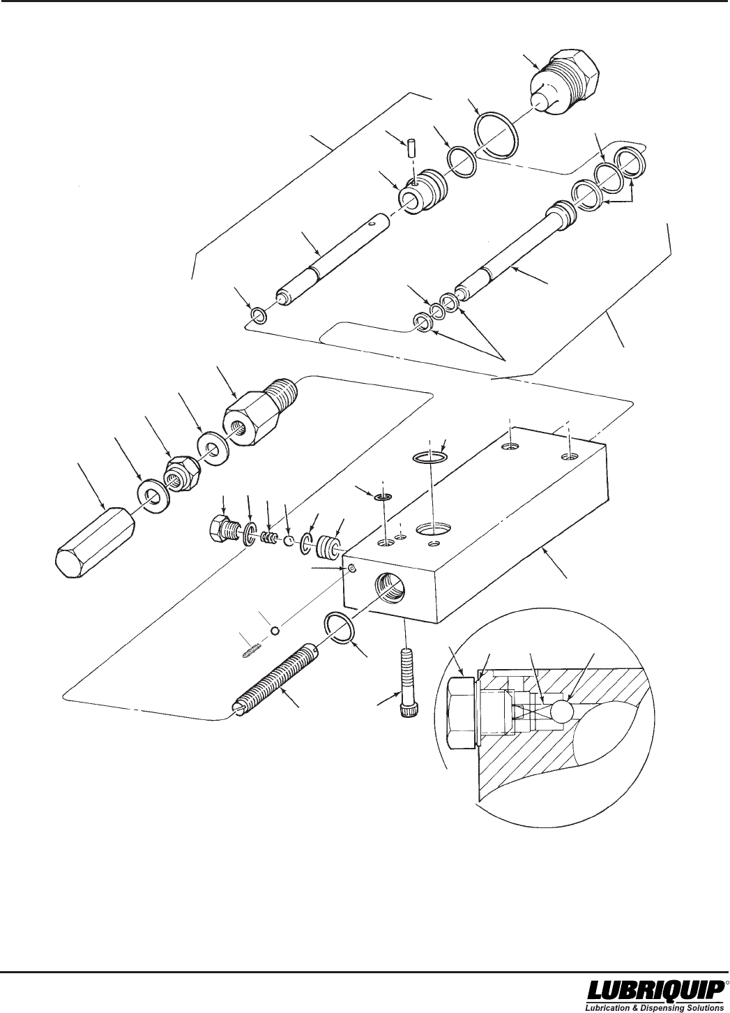
42000Modu-Flo® System
R
3-11/(3-12 Blank)
7*
CHECK VALVE COMPONENTS
PREVIOUS TO L93
(December 1993)
27*
28+ FOR H3
OPTION
(HLJ-5X)
25+
26+
6
5+
4+
3+
2
FOR H1
OPTION
(HLJ-5)
1
21+
17
18+
19
18+
20
29+
15+
16+
11 12+
13+
14+ 23+ 22+
9+
10
30 12+ 13+ 14+
8
31
6
32
6
‘
Figure 3-3. Hydraulic Pump Options H1 and H3 - Exploded View
* Not Available as Replacement Parts.
+ Included in Repair Kit. Refer to Page 3-10 for Repair Kits
*** SEE NOTE ON PAGE 4.2
TEST/AIR
PURGE PORT
***

42000Modu-Flo® System
R
3-13
3.5 HYDRAULIC PUMP MAINTENANCE
(OPTION H2)
3.5.1 General. Maintenance tips, disassembly and
assembly procedures for hydraulic pump Option H2 are
discussed in Paragraphs 3.5.2 through 3.5.4. An exploded
view of the pump is shown Figure 3-4 and should be
referred to during the discussion.
3.5.2 Hydraulic Pump Option H2 Maintenance Tips.
3.5.2.1 The only maintenance required on the hydraulic
pump Option H2 is to check for the following:
a. Check four socket-head screws (11, Figure 3-4) to
make sure they are tight. Loose screws could allow air
and/or lubricant to leak between the pump and the
manifold. This condition could result in erratic pump
output.
b. Check for leakage past gasket (15). Replace gasket if
required.
c. Check jam nut (21) to make sure it is tight against
adjustment screw body (19). If the jam nut is loose, the
adjustment screw (13) could rotate and cause the
pump output to change. This condition could also
result in lubricant leakage or in air being sucked into
the lubricant.
3.5.2.2 If internal components of the pump are defective it
will usually result in erratic pump operation or output.
Section 9 of the manual lists causes and solutions for
problems which could occur in the Modu-Flo system. Before
disassembling any pump, refer to Section 9. The problem
may be caused by other conditions which can be checked
first before breaking down the pump.
3.5.3 Disassembly of Hydraulic Pump Option H2. The
procedure below describes complete disassembly of a
pump. However, you only need to disassemble to your
specific area of concern.
3.5.3.1 The disassembly procedure for the hydraulic pump
Option H2 is as follows:
sembled. If adjustment screw (13) requires removal,
perform the following:
(1) Remove adjustment screw cap (22) from adjust-
ment screw (13). Butt the adjustment screw cap
(21) against jam nut (22) and use the stamped
numbers on the cap to measure how far the
adjustment screw (13) extends from the jam nut.
Record this dimension.
(2) Remove jam nut (21) and two gaskets (20).
Discard gaskets.
(3) Remove adjustment screw (13) by screwing it
towards the hex portion of the adjustment screw
body (19) until it is free.
d. Remove cylinder cap (6). Remove and discard o-ring
(5).
e. Use wooden dowel or soft rod to push hydraulic piston
(2) and lube piston (1) from hydraulic cylinder (7).
Remove and discard o-rings (4 and 9) and backup
rings (24).
f. Separate hydraulic piston (2) from lube piston (1) by
removing groove pin (3).
3.5.4 Assembly of Hydraulic Pump Option H2.
NOTE
Use new o-rings and gaskets when assem-
bling pump. Lubricate all o-rings and sliding
parts with the lubricant which is used in the
system.
3.5.4.1 Assemble the hydraulic pump Option H2 according
to the following procedure:
a. Insert lube piston (1) into hydraulic piston (2). Insert
groove pin (3) to secure the assembly.
b. Install new o-ring (4) and backup rings (24) on hydraulic
piston (2). Install new o-ring (9) on lube piston (1). Push
piston assembly through hydraulic cylinder (7) into body
(10).
c. Install new o-ring (5) on cylinder cap (6). Screw cylinder
cap into hydraulic cylinder (7) and tighten securely.
d. Insert smaller end of adjustment screw (13) into
adjustment screw body (19). Rotate adjustment screw
(13) until smaller end is protruding from hex portion of
adjustment screw body (19).
e. Install new o-ring (12) on adjustment screw body (19)
and install adjustment screw body in body (10). Tighten
securely.
f. Install jam nut (21) and two new gaskets (20), one on
each side of jam nut, on adjustment screw (13). Butt
adjustment screw cap (22) against jam nut (21) and
turn adjustment screw (13) until the length it extends
beyond the jam nut is the same as the length recorded
during disassembly.
g. Install adjustment screw cap (22) on adjustment screw
(13).
h. Install new o-ring (26) on check seat (25) and install
check seat assembly into pump body. Install new ball
(29) and new check valve spring (16) into body (10).
NOTE
Figure 3-4 shows hydraulic cylinder (7) sepa-
rated from body (10). To achieve disassembly
to this level requires special tools to remove
hydraulic cylinder retainer (23). Normally, this
level of disassembly is only performed at the
factory. If scoring or wear marks are evident on
the inner diameter of hydraulic cylinder (7) or
body (10), the pump cannot be serviced and
should be replaced.
a. Separate pump from manifold by removing four socket-
head screws (11). Remove and discard three o-rings
(9) and one o-ring (18).
b. Remove enclosure screw (14). Remove and discard
gasket (15), check valve spring (16), steel ball (29),
check seat (25), and o-ring (26).
c. Remove adjustment screw body (19) and o-ring (12)
from body (10). Discard o-ring (12). Removal of
adjustment screw (13) from adjustment screw body
(19) will change output setting when pump is reas-

Modu-Flo® System 42000
R
3-14
Place new gasket (15) on enclosure screw (14). Screw
enclosure screw (14) into body (10) and tighten securely.
i. Install three new o-rings (9) and one new o-ring (18) into
body (10). Securely attach pump to manifold using four
socket-head screws (11).
3.5.4.2 When the assembly steps listed above have been
completed, adjust the pump output as described in Para-
graph 3.2.2.
3.5.5 Hydraulic Pump Option H2 Parts List. Table 3-4
identifies the parts indexed in Figure 3-4.
Table 3-4. Hydraulic Pump Option H2 Parts List
Item
Number Part Number Description Quantity
521-000-031 PUMP ASSEMBLY, HL-25 (Option H2) --
1 PISTON, Lube 1
2 521-000-310 PISTON, Hydraulic 1
3 411-101-660+ PIN, Groove, part of kit 521-001-061 1
4 422-021-160+ O-RING, Part of kit 521-001-061 1
5 422-011-220+ O-RING, Part of kit 521-001-061 1
6 521-000-300 CAP, Cylinder 1
7 521-000-290 CYLINDER, Hydraulic 1
8 422-010-200+ O-RING, Part of kit 521-001-061 1
9 423-700-111+ O-RING, Part of kit 521-001-061 1
10 BODY, Pump 1
11 419-130-070+ SCREW, Socket-head, 1/4-20 x 1-1/4 inch 4
12 422-011-140+ O-RING, Part of kit 521-001-061 1
13 521-003-010 SCREW, Adjustment 1
14 521-008-460 SCREW, Enclosure 1
15 500-132-000+ GASKET, Part of kit 521-001-061 1
16 511-893-000+ SPRING, Check valve, part of kit 521-001-061 1
17 401-030-030+ BALL, Steel, 3/16 inch, part of kit 521-001-061 1
18 423-700-114+ O-RING, Part of kit 560-001-061 1
19 521-003-040 BODY, Adjustment screw 1
20 439-040-070+ GASKET, Stat-O-Seal, part of kit 521-001-061 2
21 410-702-033+ NUT, Jam, 7/16-20 1
22 521-002-980 CAP, Adjustment screw 1
23 521-000-330 RETAINER 1
24 423-700-063+ RING, Backup, part of kit 560-001-061 1
25 521-008-450+ SEAT, Check valve, part of kit 560-001-061 1
26 422-010-080+ O-RING, Part of kit 560-001-061 1
27 423-700-113+ O-RING, Part of kit 560-001-061 5
30 521-000-050 SCREW, Enclosure 1
31 401-010-010+ BALL, Steel 1/8” Dia. 1
32 417-450-020+ SCREW, Set 10-32”x1/4” 1
33 411-700-763+ ROLL PIN 1
-- 560-001-061 REPAIR KIT (consists of Items 3, 4, 5, 8, 9, 11,12, 15 thru 18, 1
20, 21, 24 thru 27 and 31 thru 33)
-- 521-001-401 PUMP ADJUSTMENT ASSEMBLY (consists of 1
Items 13 and 19 thru 22)
* Not Available as Replacement Parts
+ Included in Repair Kit.
*
*
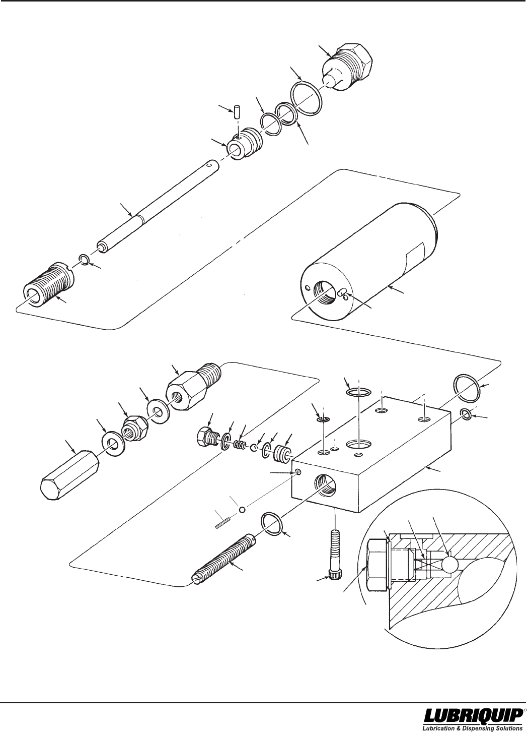
42000Modu-Flo® System
R
3-15/(3-16 Blank)
CHECK VALVE COMPONENTS
PREVIOUS TO L93
(December 1993)
7
8+
27+
12+
13
10*
17+
16+
15+
18+
27+
14 15+
17+ 25+
26+
16+
30
11+
9+
23
22
20+
21+
20+
19
1*
2
3+ 4+
5+
6
24+
32+
31+
6
6
‘
Figure 3-4. Hydraulic Pump Option H2 - Exploded View
33+
* Not Available as Replacement Parts.
+ Included in Repair Kit. Refer to Page 3-14 for Repair Kits
*** SEE NOTE ON PAGE 4.2
TEST/AIR
PURGE PORT
***

42000Modu-Flo® System
R
OPERATION AND
SERVICE INSTRUCTIONS
Modu–Flo®
System
4-1
SECTION 4
MANIFOLDS
4.1 DESCRIPTION ........................................................... 4-1
4.1.1 General ........................................................... 4-1
4.2 PREPARATION FOR USE .......................................... 4-1
4.2.1 Mounting ......................................................... 4-1
4.2.2 Connection to Other Components ................. 4-1
4.3 MAINTENANCE .......................................................... 4-1
4.1 DESCRIPTION
4.1.1 General. Two modular-design manifolds are
available. Either manifold is designed to have any of the
pneumatic or hydraulic pumps mount directly to it. The
pump-to-reservoir manifold attaches directly to the base of
the lubricant reservoir or tank. The pump-to-wall manifold is
used to mount the lubricant pump in a remote location,
separate from the lubricant reservoir or tank.
4.1.1.1 The manifolds contain the pneumatic (or hydraulic)
porting and lubricant lines necessary to operate the pump
and to direct the lubricant flow. A shutoff is built into the
manifold to prevent lubricant from leaking from the reservoir
or tank when the pump is removed.
4.1.1.2 Table 4-1 lists the operating ports used on the
manifolds. Each port is identified by stamped lettering.
Table 4-2 lists the part numbers of the manifolds accesso-
ries. Manifolds and accessories can be ordered separately
or as a combination package. Figure 4-1 shows a typical
manifold with various accessories connected to the lube
ports.
4.2 PREPARATION FOR USE
4.2.1 Mounting. Pump-to-reservoir manifolds mount
directly to the base of the reservoir or tank with two 3/8-16
socket-head screws. Pump-to-wall manifolds require that
the surface that the manifold will be attached to has two 3/8-
16 tapped holes 2-1/4 inches apart. The manifold must be
mounted so that when the pump is mounted the enclosure
screw on the pump will be on top. This will ensure proper
bleeding and priming of the system.
4.2.2 Connection to Other Components. Four 1/4-20
tapped holes are provided on the manifold for pump
attachment. The holes are laid out in a way that prevents the
pump from being mounted incorrectly. The operating ports,
listed in Table 4-1, must be connected by hose or tubing to
their appropriate locations.
4.3 MAINTENANCE
4.3.1 There is little maintenance required on the mani-
fold assemblies. All fittings and accessories used on the
unit should be tightened to avoid leakage. If any accessory
shows evidence of failure it may be removed by simply
unscrewing it from the manifold. Refer to disassembly
procedures in Section 2 for draining techniques. The pump
does not need to be removed from the manifold but it may
be desired if space is limited.
NOTE
Ensure all lubricant is drained from reservoir
before removing manifold.

Modu-Flo® System 42000
R
4-2
Table 4-1. Operating Ports on Modu-Flo Manifolds
Port Name Function
DA Single-acting model pumps:
(Double Port is fitted with a plastic vent orifice plug so
that air can be exhausted on piston return
stroke.
Double acting model pumps:
Port has air or hydraulic supply connected to it.
Fluid directed to this port causes the pump to
retract to the loading position.
GAUGE Port for attaching a pressure gauge to indicate
pump output pressure. This port is common to
the LUBE OUT port.
IND Port for attaching a blowout or pressure
indicating assembly. This port is common to
the LUBE OUT port.
SYS FILL Port for attaching an inlet check valve. This
allows the lubrication lines to be filled by an
outside source of lubricant so that the pump
does not cycle excessively when filling the
system.
LUBE OUT Port that the system being lubricated is
connected to. An outlet check valve is installed
here.
SA Port has a pneumatic or hydraulic supply
(Single source connected to it. Fluid directed to this
Acting) port causes the pump to dispense.
TEST Port is used for bleeding air out of pump. Back
out setscrew one or two turns while pump is in
the dispense stroke. Close setscrew when
pump is on return stroke to prevent air from
being sucked in. Repeat process until air-free
lubricant comes from vent hole.
LUBE IN Port that the lubricant reservoir or tank outlet
Pump-to- is connected to.
Wall (Re-
mote) Mani-
fold Only
On newer units, the test port has been relocated to the
adjustment end of the pump body. The use and function
of this port is the same in either location.
Table 4-2. Manifolds and Manifold Accessories
Item Part Number
Pump-to-Reservoir Manifold Only 521-001-540
Pump-to-Reservoir Manifold Assembly: 521-001-180
Includes outlet check valve, System
fill check valve,blowout assembly,
and pressure gauge
Pump-to-Wall (Remote) Manifold Assembly: 521-001-170
Includes outlet check valve, system
fill check valve, and blowout assembly
Pump-to-Reservoir Manifold Combination: 521-001-790
Includes outlet check valve, system fill
check valve, tubed blowout assembly,
and pressure gauge
Pump-to-Wall (Remote) Manifold
Combination: 521-001-780
Includes outlet check valve, system fill
check valve, and blowout assembly
for high pressure alarm.
Outlet Check Valve 509-360-030
System Fill Check Valve 509-365-030
Elbow, 1/4 inch pipe 509-113-000
Pipe Plug, 1/4 inch 508-975-000
Plastic Vent Plug, 1/4 inch 521-001-160
(Located in D.A. Port) (Yellow)
Standard Blowout Assembly (1450 psi) 509-206-100
Tubed Blowout Assembly (1450 psi) 509-220-101
Bag of 6 Discs (1450 psi) 560-900-270
Standard Pressure Gauge (0-3,000 psi) 543-362-000
Liquid-filled Pressure Gauge (0-3,000 psi) 543-711-380
Manifold to Reservoir
O-Ring (Buna-N) 422-010-210
(Included with pump to reservoir manifold assemblies)
* Refer to Section 6 for kits in other pressure ranges.
Acting)
Above items are for manifolds with 1/4” NPSF ports.
Consult factory for manifolds and accessories with SAE,
BSPP, and metric threads.
**
**
*
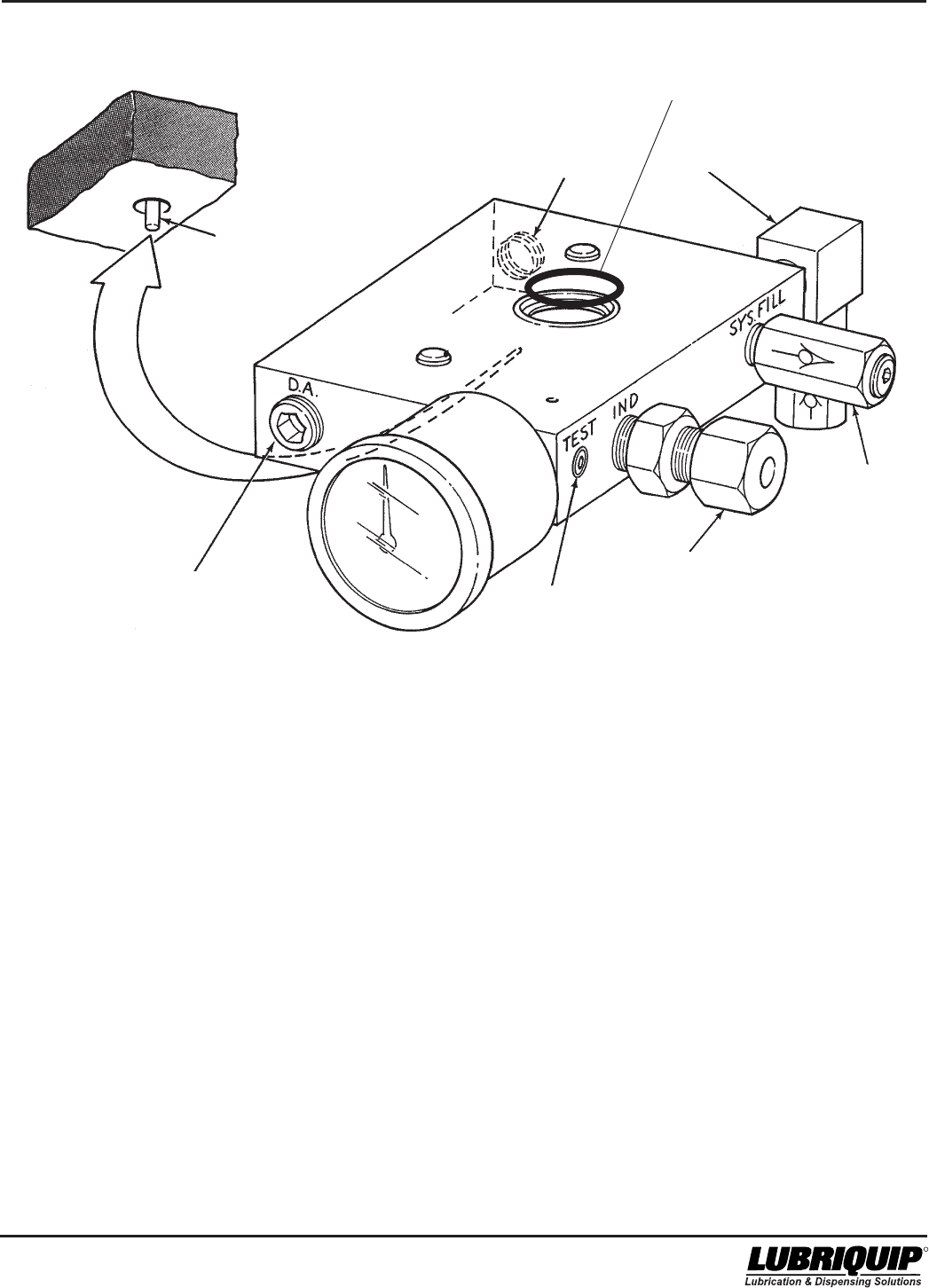
42000Modu-Flo® System
R
4-3/(4-4 Blank)
DOUBLE ACTING
(D.A.) PORT
YELLOW VENT PLUG
TEST/AIR
PURGE PORT
BLOWOUT
ASSEMBLY
LUBE
SYSTEM
OUTLET
SINGLE ACTING
(S.A.) PORT
PLUNGER
O-RING
P/N 422-010-210
* This port is used to manually fill system lube lines.
This is not the reservoir fill port. See figure 2-1 on
page 2-5, item 15 for location of grease reservoir fill.
LUBE SYSTEM
FILL
CHECK VALVE *
**
Figure 4-1. Typical Manifold Assembly
On newer units, the test port has been
relocated to the adjustment end of the pump
body. The use and function of this port is the
same in either location.
**

5-1
42000Modu-Flo® System
R
OPERATION AND
SERVICE INSTRUCTIONS
Modu–Flo®
System
SECTION 5
LOW-LEVEL SWITCHES
5.4.1 General .......................................................... 5-4
5.4.2 Oil Tank and Reservoir 10-Watt
Low-Level Assembly Maintenance Tips ....... 5-4
5.4.3 Disassembly of Oil Tank and Reservoir
10-Watt Low-Level Assemblies .................... 5-4
5.4.4 Assembly of Oil Tank and Reservoir
10-Watt Low-Level Assemblies .................... 5-4
5.4.5 Oil Tank and Reservoir 10-Watt
Low-Level Assemblies Parts List ................. 5-4
5.5 GREASE RESERVOIR LOW-LEVEL ASSEMBLY
MAINTENANCE (OPTION L4) ................................... 5-5
5.5.1 General .......................................................... 5-5
5.5.2 Grease Reservoir Low-Level Assembly
Maintenance Tips .......................................... 5-5
5.5.3 Disassembly of Grease Reservoir
Low-Level Assembly ..................................... 5-5
5.5.4 Assembly of Grease Reservoir
Low-Level Assembly ..................................... 5-6
5.5.5 Grease Reservoir Low-Level Assembly
Parts List ....................................................... 5-6
5.1 DESCRIPTION
5.1.1 General. Several varieties of assemblies are
available to provide a signal when the lubricant level is low.
Low-level switch assemblies used on oil tanks or reservoirs
depend on floats that fall with the depletion of lubricant and
actuate contacts on the switch. Switch assemblies used on
grease reservoirs are actuated when a cable attached to the
grease follower is pulled away from the switch as the
follower reaches the low position. Switch assemblies used
in oil reservoirs and grease reservoirs are rated 15 amps.
Optional 10-watt assemblies are available for oil tanks and
reservoirs.
5.1.1.1 The low-level assemblies with a 15 amp rating are
often used to activate a warning device such as a light or
alarm. The optional 10-watt assemblies are used to provide
input to controllers which may be programmed to use the
input signal as desired.
5.1.1.2 Table 5-1 lists the low-level assemblies available
for use. Listings in the option column are used to identify the
assembly selected when a Modu-Flo system is ordered.
5.1 DESCRIPTION .......................................................... 5-1
5.1.1 General .......................................................... 5-1
5.2. MOUNTING INSTRUCTIONS ................................... 5-1
5.2.1 Oil Reservoirs and Tanks.............................. 5-1
5.2.2 Grease Cylinders .......................................... 5-1
5.3 OIL TANK AND RESERVOIR 15 AMP
LOW-LEVEL ASSEMBLY MAINTENANCE
(OPTIONS L1, L2 and L3) ......................................... 5-2
5.3.1 General .......................................................... 5-2
5.3.2 Oil Tanks and Reservoir 15 Amp
Low-Level Assembly Maintenance Tips ....... 5-2
5.3.3 Disassembly of Oil Tank and Reservoir
15 Amp Low-Level Assemblies .................... 5-2
5.3.4 Assembly of Oil Tank and Reservoir
15 Amp Low-Level Assemblies .................... 5-2
5.3.5 Oil Tank and Reservoir 15 amp
Low-Level Assemblies Parts List ................. 5-3
5.4 OIL TANK RESERVOIR 10-WATT LOW-LEVEL
ASSEMBLY MAINTENANCE (OPTIONS L5, L6
AND L7)..................................................................... 5-4
The option used is designated by the entry in the ordering
code as shown below.
MPP - XXX - XXX - XX - XX - XX - XX - XX - XXX - XX
Low-Level Option
5.2. MOUNTING INSTRUCTIONS
5.2.1 Oil Reservoirs and Tanks. To install any low-level
switch in a reservoir or tank requires the removal of the tank
cover or reservoir cap. All covers or caps are equipped with
a 1/4 inch NPT tapped hole. The low-level switch has an
adapter which threads into the hole. For complete instruc-
tions on mounting these units, refer to Paragraphs 5.3.4
and 5.4.4.
5.2.2 Grease Cylinders. The low-level switch for grease
cylinders consists of the switch itself mounted to a bracket
which is, in turn, attached to the top of the grease cylinder.
For complete instructions on mounting these units refer to
Paragraph 5.5.4.
Modu-Flo® System
5-2
42000
R
Table 5-1. Low-Level Switch Assemblies
Part Number Switch Type Switch Rating AC Used On Option
521-001-030 Single-pole, double-throw 15 amps at 115, 230 5- and 12-pint oil L1
or 480 VAC cylindrical reservoirs
521-001-040 Single-pole, double-throw 15 amps at 115, 230 20-pint oil cylindrical L2
or 480 VAC reservoir
521-001-050 Single-pole, double-throw 15 amps at 115, 230 6-pint oil cylindrical L3
or 480 VAC reservoir and all tanks
456-010-171 Single-pole, single-throw 10 watts at 115 VAC 6-pint oil cylindrical L7
reservoir and oil tanks
456-010-172 Single-pole, single-throw 10 watts at 115 VAC 5- and 12-pint oil L5
cylindrical reservoir
456-010-173 Single-pole, single-throw 10 watts at 115 VAC 20 pint oil cylindrical reservoir L6
521-001-110 Single-pole, double-throw 15 amps at 115, 230 All grease cylindrical reservoirs L4
or 480 VAC, 0.5 amp
at 115 VDC, 0.25 amp
at 230 VDC
5.3 OIL TANK AND RESERVOIR 15 AMP
LOW-LEVEL ASSEMBLY MAINTE-
NANCE (OPTIONS L1, L2 and L3)
a. Turn off all electrical power and all air supplies to the
lube system.
b. Remove cover from reservoir (Refer to Section 2.).
c. Unscrew union nut (5, Figure 5-1) from switch adapter
(2).
d. Unscrew switch adapter (2) from switch (1).
e. Remove actuating rod, part of low-level lower assembly
(4), from remaining assembly.
f. Unscrew low-level lower assembly (4) from low-level
adapter (3).
g. Unscrew low-level adapter (3) from the reservoir cover.
Remove low-level adapter (3) from union nut (5).
5.3.4 Assembly of Oil Tank and Reservoir 15 Amp Low-
Level Assemblies.
5.3.4.1 The assembly procedure is as follows:
NOTE
The procedure listed below is based on
installing a new assembly in a tank or reservoir.
If your assembly was removed for repairs, steps
a and b do not apply.
a. Remove cover from reservoir (Refer to Section 2.).
b. Remove 1/4 inch pipe plug from reservoir cover. Insert
low-level adapter (3, Figure 5-1) into union nut (5). Screw
low-level adapter (3) into the reservoir cover and tighten
securely.
WARNING
Disconnect and lock out all power from the
assembly before attempting disassembly.
Serious injury may result from electrical shock.
5.3.1 General. Maintenance tips, disassembly and
assembly procedures for low-level options L1, L2 and L3 are
discussed in Paragraphs 5.3.2, 5.3.3 and 5.3.4. A typical low-
level assembly is shown in Figure 5-1 and should be
referred to during this discussion.
5.3.2 Oil Tanks and Reservoir 15 Amp Low-Level
Assembly Maintenance Tips. No maintenance is required
on the low-level assemblies used on oil tanks and reser-
voirs. If the oil level runs down and the assembly fails to
perform as required, the unit may have to be disassembled
to replace a defective switch. Before attempting disassembly,
check all electrical connections to make sure they are secure
and check for any physical obstruction which might be
preventing the float from operating.
5.3.3 Disassembly of Oil Tank and Reservoir 15 Amp
Low-Level Assemblies.
5.3.3.1 The disassembly procedure is as follows:
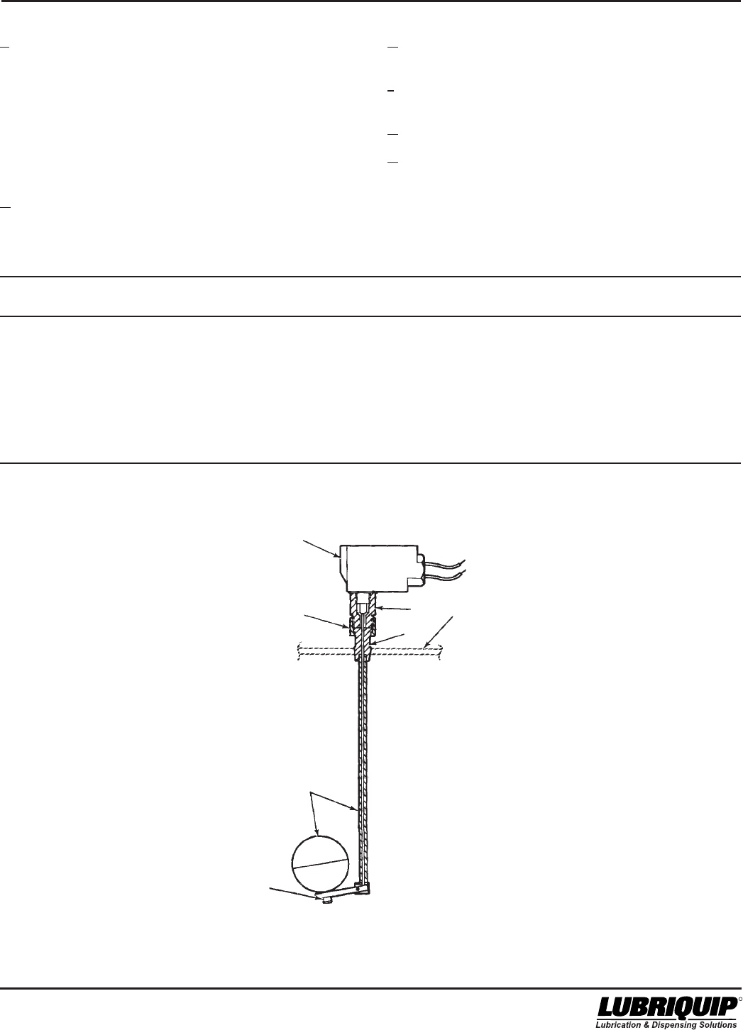
5-3
42000Modu-Flo® System
R
c. Screw low-level lower assembly (4) into low-level
adapter (3) and tighten securely. e. Screw switch adapter (2) into switch (1) and tighten
securely.
f. Screw union nut (5) onto switch adapter (2) and tighten
securely.
g. Install cover on reservoir (Refer to Section 2.).
h. Wire switch in accordance with local electrical codes.
5.3.5 Oil Tank and Reservoir 15 Amp Low-Level Assem-
blies Parts List. Table 5-2 identifies the parts indexed in
Figure 5-1.
NOTE
If float portion of low-level lower assembly was
removed during disassembly, apply Locktite to
the attaching bolt and securely attach the float to
the arm.
d. Insert the actuating rod, part of low-level lower assembly
(4), into this assembly.
Table 5-2. Oil Tank and Reservoir 15 Amp Low-Level Assemblies Parts List
Item
Number Part Number Description Quantity
521-001-030 LOW-LEVEL ASSEMBLY (5 pint, 12 pint) --
521-001-040 LOW-LEVEL ASSEMBLY (20 pint) --
521-001-050 LOW-LEVEL ASSEMBLY (6 pint) --
1 514-116-001+ SWITCH 1
2 ADAPTER, Switch 1
3 ADAPTER, Low-level 1
4 LOW-LEVEL LOWER ASSEMBLY 1
5 NUT, Union 1
*
*
*
*
2
3
5
1
COVER (REF)
4
LOCKTITE
USED AT
ASSEMBLY
+ When replacing item (1)
switch only, remove lock
nut from new switch
plunger housing before
assembling switch to
item (2) adapater.
Figure 5-1. Oil Tank and Reservoir 15 Amp Low-Level Assembly
* Not available as replacement parts.
Modu-Flo® System
5-4
42000
R
5.4 OIL TANK RESERVOIR 10-WATT
LOW-LEVEL ASSEMBLY MAINTE-
NANCE (OPTIONS L5, L6 AND L7)
5.4.1 General. Maintenance tips, disassembly and
assembly procedures for low-level options L5, L6 and L7
are discussed in Paragraphs 5.4.2, 5.4.3 and 5.4.4. A
sectional view of a low-level assembly is shown in Figure 5-
2 and should be referred to during the discussion.
5.4.2 Oil Tank and Reservoir 10-Watt Low-Level
Assembly Maintenance Tips. No maintenance is required
on the 10-watt low-level assemblies used on oil tanks and
reservoirs. If the oil level runs down and the assembly fails
to perform as required the unit may have to be disas-
sembled to replace a defective switch. Before attempting
disassembly, check all electrical connections to make sure
they are secure and check for any physical obstructions
which might be preventing the float from operating.
5.4.3 Disassembly of Oil Tank and Reservoir 10-Watt
Low-Level Assemblies.
5.4.3.1 The disassembly procedure for oil tank and
reservoir 10-watt low-level assemblies is as follows:
WARNING
Disconnect and lock out all power from the
assembly before attempting disassembly.
Serious injury may result from electrical shock.
a. Turn off all electrical power and air supplies to the lube
system.
b. Disconnect the two 22 AWG wires from the terminal
box. Disconnect adapter (1, Figure 5-2) from the
conduit.
c. Remove the cover from the tank or reservoir (Refer to
Section 2.).
d. Unscrew nipple (2) from adapter (1). Be careful not to
twist the wires too much.
e. Unscrew nipple (2) from coupling (3).
f. Unscrew coupling (3) from switch (4).
g. Unscrew adapter (1) from the reservoir cover.
5.4.4 Assembly of Oil Tank and Reservoir 10-Watt Low-
Level Assemblies.
5.4.4.1 The assembly procedure is as follows:
NOTE
The procedure listed below is based on
installing a new assembly in a tank or reservoir.
If your assembly was removed for repairs,
steps a and b do not apply.
a. Remove the cover from the reservoir (Refer to Section
2.).
b. Remove the 1/4 inch pipe plug from the cover. Screw
adapter (1, Figure 5-2) in and tighten it securely.
c. Guide the two 22 AWG wires from switch (4) through
coupling (3). Screw coupling (3) onto switch (4) and
tighten securely.
d. Guide two 22 AWG wires through nipple (2). Screw
nipple into coupling (3).
e. Guide the two 22 AWG wires through adapter (1). Screw
nipple into adapter (1). Be careful not to twist the wires
too much. Tighten the connection.
f. Connect switch (4) in accordance with local electrical
codes.
5.4.5 Oil Tank and Reservoir 10-Watt Low-Level
Assemblies Parts List. Table 5-3 identifies the parts
indexed in Figure 5-2.
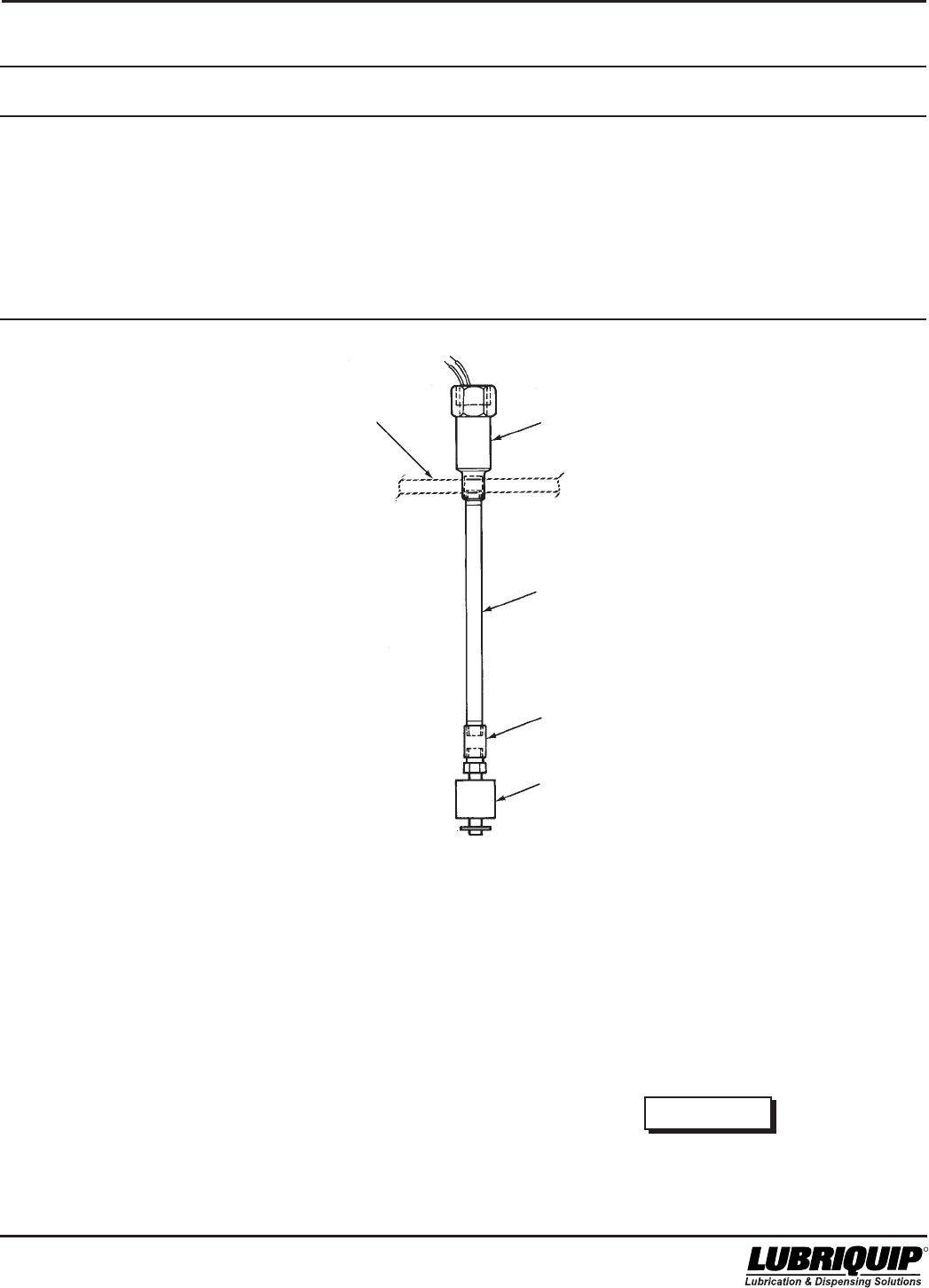
5-5
42000Modu-Flo® System
R
5.5 GREASE RESERVOIR LOW-LEVEL ASSEMBLY MAINTENANCE
(OPTION L4)
5.5.1 General. Maintenance tips, disassembly and
assembly procedures for low-level assembly option L4 are
discussed in Paragraphs 5.5.2, 5.5.3 and 5.5.4. A sectional
view of a typical assembly is shown in Figure 5-3 and should
be referred to during the discussion.
5.5.2 Grease Reservoir Low-Level Assembly Mainte-
nance Tips. No maintenance is required on the low-level
assemblies used on grease reservoirs. If the grease level
runs down and the assembly fails to perform as required,
the low level assembly may have to be disassembled to
replace a defective switch. Before attempting disassembly,
check all electrical connections to make sure they are secure
and check for any physical obstruction which might be
preventing the switch from operating.
5.5.3 Disassembly of Grease Reservoir Low-Level
Assembly.
5.5.3.1 The disassembly procedure for the grease reservoir
low-level assembly is as follows:
4
RESERVOIR
COVER (REF)
3
2
1
WARNING
Disconnect and lock out all power from the
assembly before attempting disassembly.
Serious injury may result from electrical shock.
Table 5-3. Oil Tank and Reservoir 10-Watt Low-Level Assemblies Parts List
Item
Number Part Number Description Quantity
456-010-172 LOW-LEVEL ASSEMBLY (5 pint, 12 pint) --
456-010-173 LOW-LEVEL ASSEMBLY (20 pint) --
456-010-171 LOW-LEVEL ASSEMBLY (6 pint) --
1 541-603-001 SWITCH, 10 watts, 115 VAC, NC SPST 1
541-603-002 OPTIONAL SWITCH, 10 watts, 115 VAC, NO, SPST
2 COUPLING 1
3 NIPPLE 1
4 ADAPTER 1
Figure 5-2. Oil Tank and Reservoir 10-Watt Low-Level Assembly
*
*
*
* Not available as replacement parts.
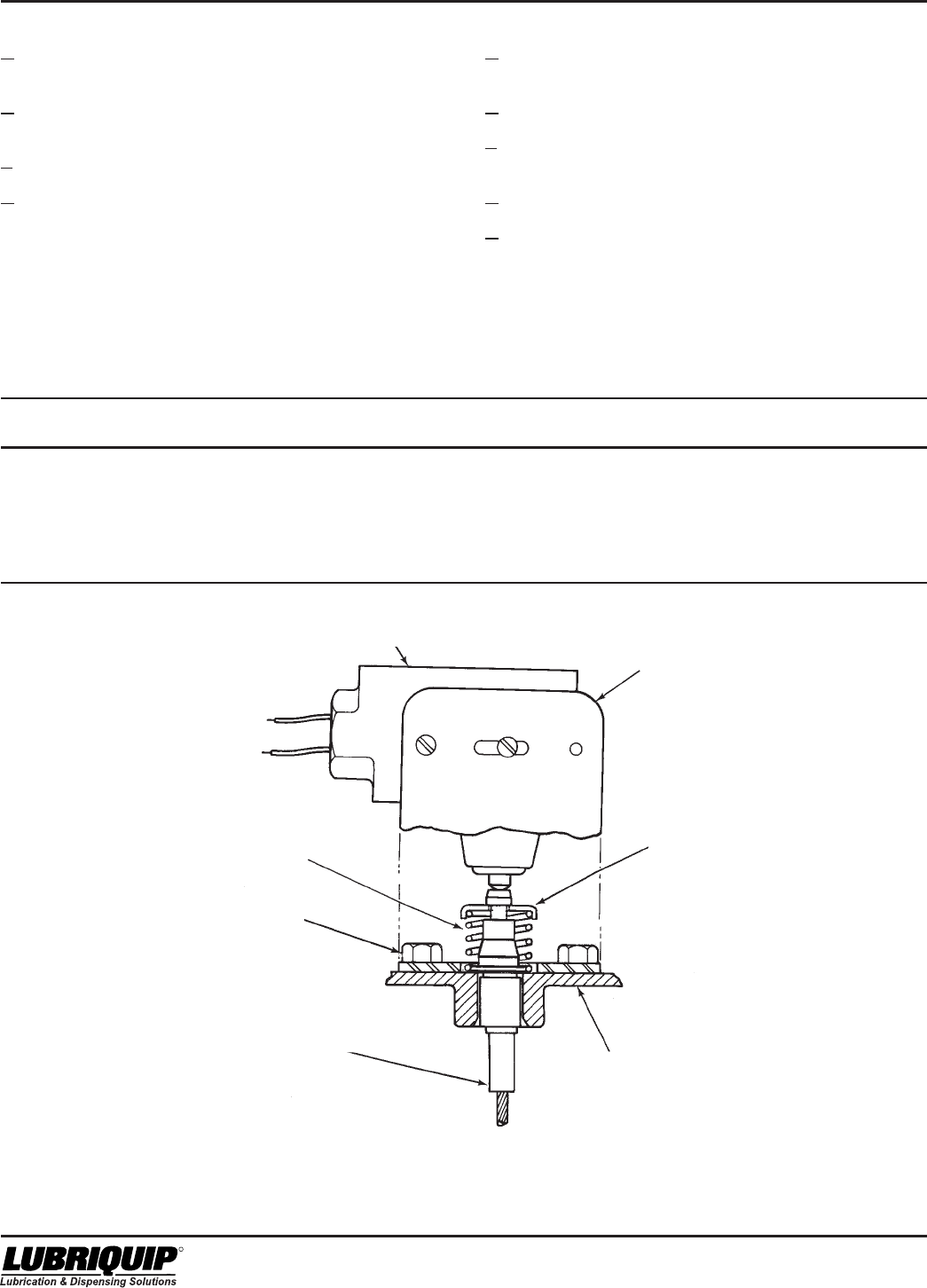
Modu-Flo® System
5-6
42000
R
a. Disconnect and lock out all electrical power and air
supplies to the lube system.
b. Disconnect switch (1, Figure 5-3) from terminal box.
Remove switch (1) from bracket (2).
c. Remove retainer ring (3) and spring (5).
d. Remove three self-tapping screws (4) and bracket (2).
5.5.4 Assembly of Grease Reservoir Low-Level
Assembly.
5.5.4.1 The procedure for assembly of the grease reservoir
low-level assembly is as follows:
a. Attach bracket (2) to grease reservoir cover using three
self-tapping screws (4).
b. Place spring (5) over tip of level indicator.
c. Compress spring (5) and place retainer ring (3) be-
tween spring and tip of level indicator.
d. Attach switch (1) to bracket (2).
e. Wire switch (1) in accordance with local electrical codes.
Table 5-4. Grease Reservoir 15 Amp Low-Level Assembly Parts List
Item
Number Part Number Description Quantity
521-001-110 LOW-LEVEL SWITCH ASSEMBLY (Option L4) --
1 529-726-001 SWITCH 1
2 514-191-001 BRACKET 1
3 060251 RING, Retainer 1
4 415-210-010 SCREW, Self-tapping 3
5 542-939-000 SPRING 1
Figure 5-3. Grease Reservoir Low-Level Assembly
2
GREASE RESERVOIR
CABLE ASSEMBLY (REF) GREASE RESERVOIR
CAP (REF)
3
1
5
4
5.5.5 Grease Reservoir Low-Level Assembly Parts List.
Table 5-4 identifies the parts indexed in Figure 5-3.

6-1
42000Modu-Flo® System
R
OPERATION AND
SERVICE INSTRUCTIONS
Modu–Flo®
System
SECTION 6
HIGH-PRESSURE AND BLOWOUT SWITCHES
6.4.3 Assembly/Disassembly of High-Pressure
Switch ............................................................ 6-3
6.4.4 High-Pressure Switch Parts Lists ................ 6-3
6.5 RESERVOIR BLOWOUT SWITCH MAINTENANCE
(OPTIONS P2 and P3) .............................................. 6-4
6.5.1 General .......................................................... 6-4
6.5.2 Reservoir Blowout Switch
Maintenance Tips .......................................... 6-4
6.5.3 Assembly/Disassembly of Blowout Switch .. 6-4
6.5.4 Reservoir Blowout Switch Parts Lists........... 6-4
6.6 TANK BLOWOUT SWITCH MAINTENANCE
(OPTION P4) ............................................................. 6-6
6.6.1 General .......................................................... 6-6
6.6.2 Tank Blowout Switch Maintenance Tips ....... 6-6
6.6.3 Assembly/Disassembly of Blowout Switch .. 6-6
6.6.4 Tank Blowout Switch Parts List ..................... 6-6
6.1 DESCRIPTION .......................................................... 6-1
6.1.1 High-Pressure Switches ............................... 6-1
6.1.2 Blowout Switches .......................................... 6-1
6.1.3 Blowout Disc ................................................. 6-1
6.1.4 High-Pressure and Blowout Switch
Options .......................................................... 6-2
6.2 HIGH-PRESSURE SWITCH ADJUSTMENT............. 6-2
6.2.1 General .......................................................... 6-2
6.2.2 High-Pressure Switch Adjustment
Procedures .................................................... 6-2
6.1 DESCRIPTION
6.1.1 High-Pressure Switches. High-pressure switches
may be plumbed into the lubricant output circuit to provide
an electrical signal when excessive pressure is being
approached. The pressure switch is factory set at 1150 psig
(79 bar) and is used with a standard blowout disc rated at
1450 psig (100 bar). When output pressure reaches 1150
psig (79 bar), contacts on the switch will actuate and provide
a warning signal to an external device. If the problem
causing the high pressure is not corrected, the pressure will
continue to rise. When pressure reaches 1450 psig
(100 bar) the blowout disc will rupture and relieve the
pressure. The setting of the pressure switch is adjustable.
Adjustment procedures are discussed in Paragraph 6.2.2.
6.1.2 Blowout Switches. High-pressure blowout switch
assemblies may be plumbed into the lubricant circuit to
provide an electrical signal when the blowout disc has
ruptured. On these assemblies, a tubed blowout assembly
is used. The tubed blowout allows lubricant to flow from the
ruptured blowout disc, through tubing up to an indicator
assembly. The indicator assembly has a built-in check valve
which will allow the lubricant to reach a pressure sufficient
enough to extend a plunger. The extended plunger actuates
a switch which will allow a signal to be sent to an alarm or
other device. Lubricant from the indicator is directed through
tubing and is returned to the inlet port on the reservoir or
tank. The indicator will retain the plunger in the extended
position even if lubricant pressure is reduced. The plunger
must be manually depressed to release the switch and
return the indicator to its normal position.
6.1.3 Blowout Disc. The standard blowout disc, rated at
1450 psig (100 bar), may be used on any unit. This assem-
bly does not provide any electrical signal when the blowout
pressure has been reached. The blowout disc will rupture at
the high pressure and the lubricant escaping from the
blown disc will provide a visual indication of failure. Discs
rated at higher pressures than 1450 psig (100 bar) are
available separately in kits of six. For identification pur-
poses, discs are color coded. Table 6-1 lists the discs
available and the kit number for each.
6.3 MOUNTING INSTRUCTIONS ................................... 6-3
6.4 HIGH-PRESSURE SWITCH MAINTENANCE
(OPTION P1) ............................................................. 6-3
6.4.1 General .......................................................... 6-3
6.4.2 High-Pressure Switch Maintenance Tips ..... 6-3
Table 6-1. Blowout Discs and Kits
Kit No.
Rating (contains
Disc Part No. Color psi (bar) 6 discs)
509-292-000 Yellow 1450 (100) 560-900-270
509-293-000 Red 1750 (121) 560-900-280
509-294-000 Orange 2050 (141) 560-900-290
509-295-000 Aluminum 2350 (162) 560-900-300
509-297-000 Blue 2950 (203) 560-900-320
509-298-000 Purple 3250 (224) 560-900-330
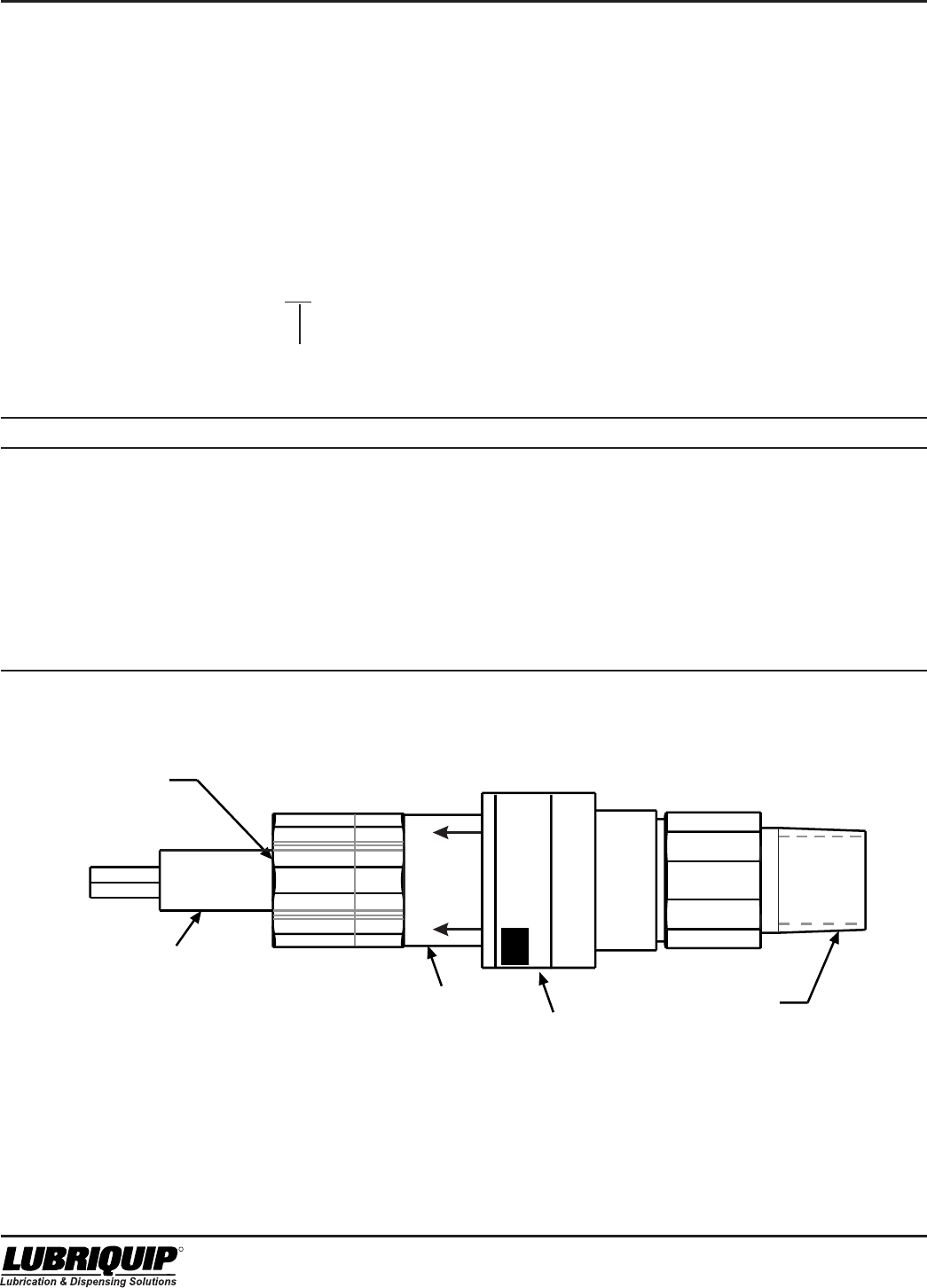
Modu-Flo® System
6-2
42000
R
6.1.3.1 When any pressure or blowout switch is actuated,
personnel must determine the cause for the rise in pres-
sure. After the cause has been corrected, any blowout discs
which have been ruptured will need to be replaced with an
approved disc.
6.1.4 High-Pressure and Blowout Switch Options. Table
6-2 lists the pressure and blowout switch options available
for use. Listings in the option column are used to identify the
assembly selected when a Modu-Flo system is ordered. The
option used is designated by the entry in the ordering code
as shown below:
MPP - XXX - XXX - XX - XX - XX - XX - XX - XXX - XX
Pressure Indicator Option
Table 6-2. High-Pressure and Blowout Switch Assemblies
Part Number Description Electrical Ratings Used On Option
521-001-220 Pressure Switch Kit 5 amp at 115/230 VAC Any reservoir P1
521-001-190 Blowout Assembly 15 amp at 115,230 or 480 VAC 5-pint or 5-pound P2
0.5 amp at 115 VDC cylindrical reservoir
0.25 amp at 230 VDC
521-001-200 Blowout Assembly 15 amp at 115, 230 or 480 VAC 6, 12 or 20-pint or pound P3
0.5 amp at 115 VDC cylindrical reservoir
0.25 amp at 230 VDC
521-001-210 Blowout Assembly 15 amp at 115, 230 or 480 VAC All tanks P4
0.5 amp at 115 VDC
0.25 amp at 230 VDC
509-206-100 Blowout Disc 1450 psi None All units P5
Figure 6-1. High-Pressure Switch
FACTORY SEALED
3 WIRE CABLE
16 AWG
5 FT. LG.
RED N.O.
BLACK N. C.
WHITE COM.
1/4 NPT
1/2" FEMALE
CONNECTOR
CONDUIT
CAUTION LABEL
PRESSURE SWITCH
LUBRIQUIP, INC. A Unit of IDEX
18901 Cranwood Pkwy, Cleveland Oh
(216) 581-2000 1-800-USA-
FAX 216) 581-8945
LUBRIQUIP
542-210-120
ADJUSTMENT
COVER
MOVE
TO
ACCESS
ADJ.
6.2 HIGH-PRESSURE SWITCH
ADJUSTMENT
6.2.1 General. The high-pressure switch assembly has
an adjustable range from 400 to 4700 psi (28 to 324 bar). If
the pressure setting is to be changed from the standard
factory setting of 1150 psi (79 bar) the blowout disc must
also be changed. To prevent system damage, the pressure
switch setting should not exceed 80 percent of the blowout
disc rating. Table 6-3 lists the blowout discs available and
the maximum pressure switch setting to be used.
6.2.2 High-Pressure Switch Adjustment Procedures.
6-3
42000Modu-Flo® System
R
Table 6-3. Pressure Switch Settings
Maximum
Recommended
Disc Pressure Switch
Disc Rating Setting
Color psi (bar) psi (bar)
Yellow 1450 1160 (80)
(100)
Red 1750 1450 (100)
(121)
Orange 2050 1640 (113)
(141)
Aluminum 2350 1880 (130)
(162)
Blue 2950 2360 (163)
(203)
Purple 3250 2600 (179)
(224)
6.2.2.1 The adjustment procedure for the high-pressure
switch is as follows:
WARNING
•Disconnect and lock out all power from the
assembly before attempting disassembly.
Serious injury may result from electrical shock.
•To avoid possible system damage, change the
blowout disc to match the new pressure switch
setting. (Refer to Paragraph 6.2.1.)
a. Turn off electrical power to the lube system.
b. Connect control to pressure source.
c. With power disconnected, slide cover toward electrical
terminations while twisting it to overcome friction.
d. Connect power to terminals or leads.
e. Insert screwdriver into adjustment slot and turn clock-
wise to increase setting or counter-clockwise to de-
crease setting.
For setting on rise, apply desired pressure and turn
adjustment (clockwise facing cable end of pressure
switch) until switch clicks and/or tester confirms contact
transfer (Circuit across N.O. and COM. terminals
closes). For setting on fall, apply pressure equal to
normal system operating pressure. Reduce source
pressure to set point value. Turn adjustment counter-
clockwise until switch clicks and/or tester confirms
contact transfer (circuit across N.C. and COM. closes).
f. After completing adjustments, slide cover closed order
adjustment compartment. Recheck set point.
6.3 MOUNTING INSTRUCTIONS
6.3.1 All high-pressure switches and blowout options are
connected to the outlet of the manifold and mounted to
various locations on the reservoir or tank. Refer to assembly
Paragraphs 6.4.3, 6.5.3 and 6.6.3 for specific assembly
instructions.
6.4 HIGH-PRESSURE SWITCH
MAINTENANCE (OPTION P1)
6.4.1 General. Maintenance tips, disassembly and
assembly procedures for the high-pressure switch are
discussed in Paragraphs 6.4.2 and 6.4.3. A typical pressure
switch is shown in Figure 6-2 and should be referred to
during the discussion.
6.4.2 High-Pressure Switch Maintenance Tips. No
maintenance is required on the high-pressure switch. If the
switch is suspected to be defective, check all wiring to the
switch before removing any components.
NOTE
Relieve system pressure before removing any
components.
6.4.3 Assembly/Disassembly of High-Pressure Switch.
Figure 6-2 shows a typical high-pressure switch mounted to
a manifold. All components of the unit are connected by pipe
threads and are easily assembled or disassembled. The
blowout assembly (3) is connected to the IND port of the
manifold and the pressure switch (1) is connected by fittings
to the LUBE OUT port of the manifold. Normally, the only
components which may require removal or replacement are
the pressure switch (1) and the blowout disc (5). The
pressure switch (1) is easily screwed out after all electrical
connections are removed.
6.4.3.1 The blowout disc replacement procedure is as
follows:
a. Remove pressure relief nut (6) from adapter fitting (4).
b. Remove blowout disc (5).
c. Install new blowout disc (5) in pressure relief nut (6).
d. Install pressure relief nut (6) on adapter fitting (4) and
torque to 5 ft lbs.
6.4.4 Pressure Switch Parts Lists. Table 6-4 identifies
the parts indexed in Figure 6-2.
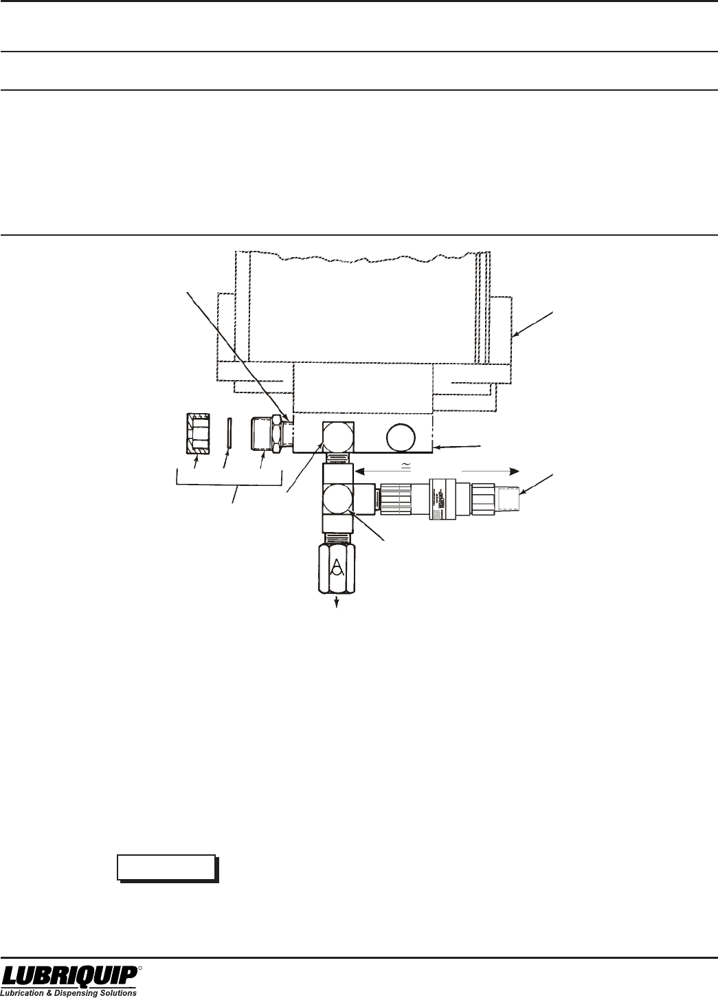
Modu-Flo® System
6-4
42000
R
Table 6-4. High-Pressure Switch Parts List
Index
Number Part Number Description Quantity
521-001-220 HIGH-PRESSURE SWITCH ASSEMBLY (Option P1) --
1 542-210-120 SWITCH, Pressure 1
2 412-380-020 TEE, Male, 1/4 inch pipe 1
3 509-206-100 BLOWOUT ASSEMBLY, 1450 psi 1
4 -- . FITTING, Adapter 1
5 -- . DISC, Blowout 1
6 -- . NUT, Pressure relief 1
6.5 RESERVOIR BLOWOUT SWITCH
MAINTENANCE (OPTIONS P2 and P3)
6.5.1 General. Maintenance tips, disassembly, and
assembly instructions for reservoir blowout switches are
discussed in Paragraphs 6.5.2, and 6.5.3. A typical reservoir
with blowout switch is shown in Figure 6-3 and should be
referred to during the discussion.
6.5.2 Reservoir Blowout Switch Maintenance Tips. No
maintenance is required on the blowout switch. If the switch
assembly is suspected to be defective, check all wiring to
the switch before removing any components.
WARNING
Disconnect and lock out all power from the
assembly before attempting disassembly.
Serious injury may result from electrical shock.
NOTE
Relieve system pressure before removing any
components.
6.5.3 Assembly/Disassembly of Blowout Switch. Figure
6-3 shows a typical blowout switch mounted on a reservoir.
All components are connected by pipe threads and tubing
and are easily assembled or disassembled. The blowout
body (14) is connected to the IND port on the manifold. The
return elbow (15) is piped into the fill port of the reservoir.
Normally, the only components which may require removal
are the switch (5), indicator assembly (10), and blowout
disc. Access to these components is easily achieved after
removal of any connective tubing.
6.5.4 Reservoir Blowout Switch Parts Lists. Table 6-5
identifies the parts indexed on Figure 6-3.
TANK OR
RESERVOIR
MANIFOLD
(REF)
LUBE OUTLET
EXISTING
LUBE
OUTLET
ELBOW
IND PORT
1
2
3
654
S.A.
Figure 6-2. High-Pressure
Switch (Rear View)
4-3/4”
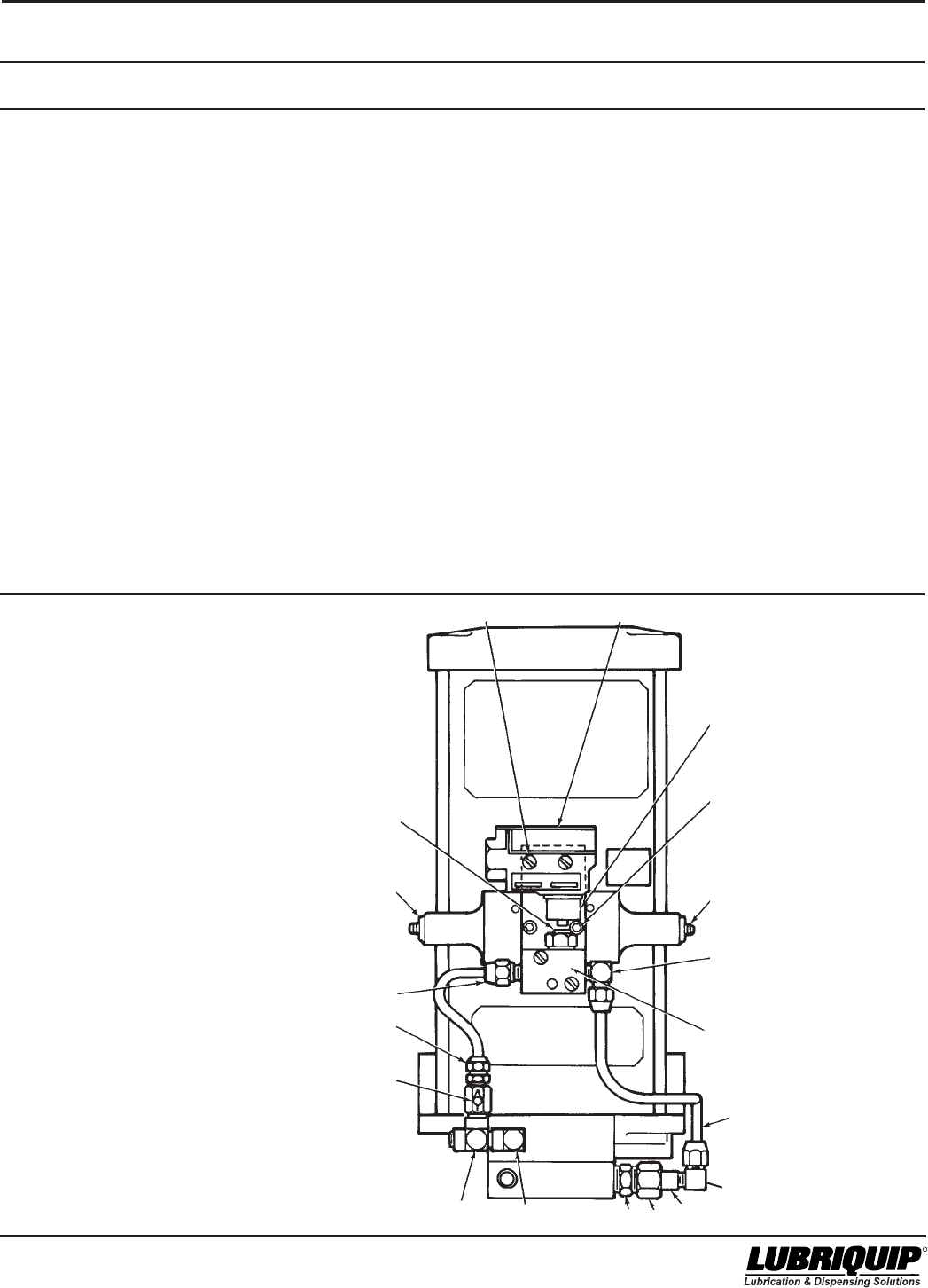
6-5
42000Modu-Flo® System
R
Table 6-5. Reservoir Blowout Switch Parts List
Item
Number Part Number Description Quantity
521-001-190 HIGH-PRESSURE BLOWOUT SWITCH ASSEMBLY (5 pint/lb) --
521-001-200 HIGH-PRESSURE BLOWOUT SWITCH ASSEMBLY (6, 12 or 20 pint/lb) --
1 521-000-760 BRACKET, Mounting, for 5 lb and 5 pt 1
521-000-770 BRACKET, Mounting, for 6 lb, 12 lb, 20 lb, 6 pt, 12 pt, and 20 pt 1
2 416-701-992 SCREW, Round head, 6-32 x 1-3/8 inch, part of 2
Part No. 511-573-030
3 421-070-050 LOCKWASHER, No. 6, part of part No. 511-573-030 4
4 410-030-050 NUT, Hex, 6-32, part of Part No. 511-573-030 2
5 529-726-001 SWITCH, Part of Part No. 511-573-030 1
6 501-967-001 BRACKET, Switch, part of Part No. 511-573-030 1
7 419-110-020 SCREW, Socket-head, 10-24 x 1/2 inch 2
8 417-060-060 SETSCREW, 1/4-20 x 1/2 inch 2
9 435-370-020 FITTING, Elbow, 1/8 NPT x 1/4 inch tube 2
10 511-160-001 INDICATOR ASSEMBLY, Part of Part No. 511-573-030 1
11+ TUBING, Copper, 1/4 inch outer diameter x 0.030 wall 3 ft
12 509-223-000 SPUD, Union 1
13 509-224-000 NUT, Union 1
14 509-208-000 BODY, Blowout 1
15 412-270-030 ELBOW, 1/4 inch NPT 1
16 412-380-020 TEE, 1/4 inch NPT 1
17 509-365-030 CHECK VALVE ASSEMBLY 1
18 435-360-030 FITTING, Straight, 1/4 tube x 1/4 inch NPT 1
-- 511-573-030 BLOWOUT AND SWITCH ASSEMBLY 1
-- 560-900-270 BLOWOUT DISCS, Bag of 6, 1450 psi 1
19 435-360-020 FITTING, Straight, 1/4 inch tube x 1/8 inch NPT 1
* See Table 6-1 for other disc pressure ratings.
+ Tubing purchased separately
Figure 6-3. Reservoir Blowout Switch
Assembly (Front View)
PLUNGER
1
19
18
17
16
2,3,4 5
14 13 12
11
10
9
8
7
6
15
9
*

Modu-Flo® System
6-6
42000
R
6.6 TANK BLOWOUT SWITCH
MAINTENANCE (OPTION P4)
6.6.1 General. Maintenance tips, disassembly, and
assembly instructions for tank blowout switches are dis-
cussed in Paragraphs 6.6.2 and 6.6.3. A typical tank with
blowout switch is shown in Figure 6-4 and should be
referred to during the discussion.
6.6.2 Tank Blowout Switch Maintenance Tips. No
maintenance is required on the blowout switch. If this switch
assembly is suspected to be defective, check all wiring to the
switch before removing any components.
WARNING
Disconnect and lock out all power from the
assembly before attempting disassembly.
Serious injury may result from electrical shock.
NOTE
Relieve system pressure before removing any
components.
6.6.3 Assembly/Disassembly of Blowout Switch. Figure
6-4 shows a typical blowout switch mounted on a tank. All
components are connected by pipe threads and tubing and
are easily assembled or disassembled. The blowout body
(15) is connected to the IND port on the manifold. The return
elbow (12) is piped into the fill port of the reservoir. Normally,
the only components which may require removal are the
switch (6), indicator assembly (8) and blowout disc. Access
to these components is easily achieved after removal of any
connective tubing.
6.6.4 Tank Blowout Switch Parts List. Table 6-6 identi-
fies the parts indexed on Figure 6-4.
Table 6-6. Tank Blowout Switch Parts List
Item
Number Part Number Description Quantity
521-001-210 BLOWOUT SWITCH ASSEMBLY (Option P4) --
1 435-360-020 FITTING, Straight, 1/8 NPT x 1/4 inch tube 2
2 416-701-992 SCREW, Round head, 6-32 x 1-3/8 inch, included in Part No. 511-573-020 2
3 421-070-050 LOCKWASHER, No. 6, included in part Kit No. 511-573-020 4
4 410-030-050 NUT, Hex, No. 6-32, included in Part No. 511-573-020 2
5 419-110-020 SCREW, Socket-head, 10-24 x 1/2 inch 2
6 529-726-001 SWITCH, Included in part No. 511-573-020 1
7 501-967-001 BRACKET, Switch, included in part No. 511-573-020 1
8 511-160-001 INDICATOR ASSEMBLY, Included in part No. 511-573-020 1
9 435-370-020 FITTING, Elbow, 1/8 NPT x 1/4 inch tube 1
10 412-380-020 TEE, 1/4 NPT 1
11 509-365-030 CHECK VALVE ASSEMBLY 1
12 435-370-030 FITTING, Elbow, 1/4 inch male pipe x 1/4 inch tube 1
13 509-223-000 SPUD, Union 1
14 509-224-000 NUT, Union 1
15 509-208-000 BODY, Blowout 1
16+ TUBING, Copper, 1/4 inch outer diameter x 0.030 wall 4 ft
-- 511-573-020 BLOWOUT SWITCH ASSEMBLY 1
-- 560-900-270 BLOWOUT DISCS, Bag of 6, 1450 psi 1
* See Table 6-1 for other disc pressure ratings.
+ Tubing purchased separately
*
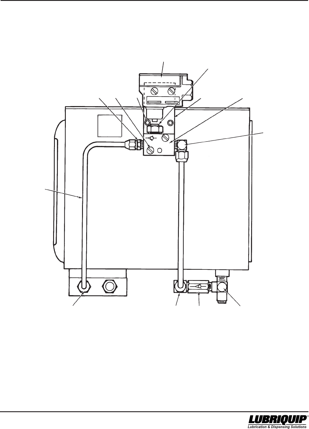
6-7
42000Modu-Flo® System
R
/(6-8 Blank)
Figure 6-4. Tank Blowout Switch Assembly (Side View)
PLUNGER
6
78
9
10
11
12
1,13,14,15
1 2,3,4 5
16
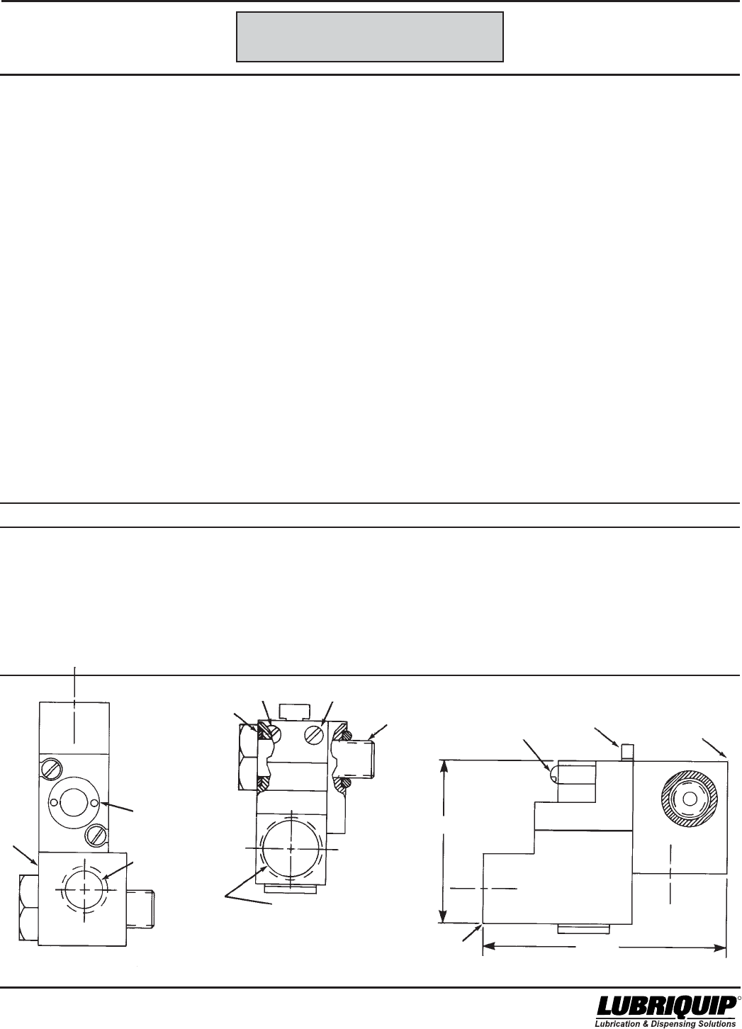
7-1/(7-2 Blank)
42000Modu-Flo® System
R
OPERATION AND
SERVICE INSTRUCTIONS
Modu–Flo®
System
SECTION 7
PNEUMATIC SOLENOID
7.1 DESCRIPTION ........................................................... 7-1
7.2 OPERATION ............................................................... 7-1
7.3 INSTALLATION ........................................................... 7-1
7.1 DESCRIPTION
The Pneumatic Solenoid Valve option S1 is designed for
use in 115 VAC applications, while the S2 option is for 24
VDC applications. The solenoid valve is supplied with the
selection plate in a normally closed configuration, making
the solenoid a two way valve. It comes equipped with a
manual override operator and with 18 inch long #18 AWG
coil lead wires.
7.2 OPERATION
When voltage is applied to the solenoid coil, the valve is
opened, allowing air to flow through to the pump manifold
and to the pneumatic piston in the pump. As air is being
supplied, the pneumatic piston moves forward and pushes
the lube piston forward which discharges lubricant to the
system. When voltage is dropped out, air flow is stopped.
The pneumatic and lube piston are returned by the piston
return spring, thus allowing the pump to reprime for the next
cycle.
7.3 INSTALLATION
Installing the solenoid valve to the pump manifold requires
making sure the o-rings (4) are in place. Mount the solenoid
valve to the pump manifold port stamped “SA” with the valve
bolt. Torque to 10-15 ft. lbs.
Table 7-1. Pneumatic Solenoid Parts List
Item Number Part Number Description Quantity
521-001-020 115 VAC SOLENOID ASSEMBLY (S1)
521-002-100 24 VDC SOLENOID ASSEMBLY (S2)
1 521-000-540 115 VAC SOLENOID VALVE WITH COIL 1
521-004-550 24 VDC SOLENOID VALVE WITH COIL 1
2 521-000-550 MANIFOLD BLOCK 1
3 521-000-560 BOLT-MOUNTING 1
4 422-010-160 O-RING 2
5 416-060-120 SCREW-#8-32 X 1-1/4 2
6 521-000-542 NO/NC “PORT PLATE”, PART OF ITEM 1 1
Figure 7-1. Pneumatic Solenoid
1/4-18 NPSF
THREAD
TORQUE
10-15 FT. LBS
352
1
2
4
55
1/2 NPSM
CONDUIT
CONNECTION
MANUAL
OVERRIDE
1/4 NPSF
"AIR INLET"
2.188
3.312
6

8-1
42000Modu-Flo® System
R
OPERATION AND
SERVICE INSTRUCTIONS
Modu–Flo®
System
SECTION 8
CONTROLLERS
8.1 DESCRIPTION .......................................................... 8-1
8.1.1 DC Timer ....................................................... 8-1
8.1.2 AC Timer........................................................ 8-1
8.1.3 TC-1000 Timer/Counter ................................ 8-1
8.1.4 WMP Maxi-Monitor ......................................... 8-1
8.2 WIRING ..................................................................... 8-2
8.2.1 DC Timer ....................................................... 8-2
8.2.2 AC Timer........................................................ 8-2
8.2.3 TC-1000 Timer/Counter ................................ 8-3
8.2.4 Maxi-Monitors ................................................ 8-3
8.1 DESCRIPTION
8.1.1 DC Timer. The DC timer is a solid-state, 12 to 32
VDC unit that energizes a DC solenoid when it is time to
start a lubrication cycle. The solenoid actuates the lubrica-
tion pump. The interval between cycles is adjustable from 1
to 10 minutes in eight steps. The duration of the lubrication
cycle is not adjustable and is 30 seconds long. The DC
Timer also features elapsed-time memory to ensure that
the interval between cycles is maintained during equipment
shutdown. A manual run button simplifies startup, testing,
and venting of lubrication lines and points. The manual run
button initiates one 30 second cycle each time it is de-
pressed. Refer to Paragraph 8.2.1 for installation instruc-
tions. Refer to bulletin 14511 for additional information.
8.1.2 AC Timer. The AC timer is a solid-state, 115/230
VAC, 50/60 Hz unit that energizes a solenoid valve when it is
time to start a lubrication cycle. The solenoid valve (See
Paragraph 8.1.1) activates the lubrication pump. The total
cycle time is adjustable from 0.5 minute to 32 hours. The
duration of the lubrication pump cycle is adjustable from 12
seconds to 13 minutes. The AC timer has a built-in memory
to keep the timer active for 1-1/2 hours during power failures
and machine shutdowns. This feature eliminates the
prelube cycle when power is reapplied after short shut-
downs. A manual run button simplifies startup, testing, and
bleeding of lubrication lines and points. When the manual
run button is depressed, it resets the system to the begin-
ning of the cycle and signals the pump to run for the
duration of the lubrication cycle. Refer to Paragraph 8.2.2 for
installation instructions. Refer to bulletin 14521 for addi-
tional information.
8.1.3 TC-1000 Timer/Counter. The TC-1000 Solid State
Timer/Counter is a microprocessor based multi-use
controller dedicated to the operation of centralized lubrica-
tion systems.
The TC-1000 schedules lube frequency either on a time or
stroke/cycle basis in values ranging from 1-9999. The
pump run interval is also selectable in time or counts over
the same range.
The TC-1000 is easily programmed in the field using four
mini push-buttons. No special training or knowledge of
computer language is necessary. During power down or
outage, data is saved in EEPROM (Electrically Erasable
Programmable Read Only Memory). When power is
restored, counting and pump status is restored to values
prior to loss of power.
Available for 115 VAC, 230 VAC, 12 VDC, or 24 VDC opera-
tion. Pump Output voltage is the same as supply voltage.
Refer to bulletin 14530 for additonal information.
8.1.4 WMP Maxi-Monitor. The WMP Maxi-Monitor is
designed to control and monitor a lubrication system and its
accessories. It can be used to schedule and monitor the
operation of lubrication pumps and divider valves in
automatic lubrication systems. The WMP is available in AC
or DC power source models.
8.1.4.1 The WMP Maxi-Monitor controls lubrication sched-
ules on either a time or a machine cycle/stroke count basis.
It will also continuously monitor and display the status of the
lubrication system it is controlling. It is capable of shutting
down a machine and lubrication system to protect it from a
loss of lubrication.
8.1.4.2 The WMP Maxi-Monitor is easily programmed. No
special training or knowledge of computer languages is
needed. Programming is done through a membrane
keypad located on the enclosure door.
Refer to bulletins 14750 and 14752 for additional
information.
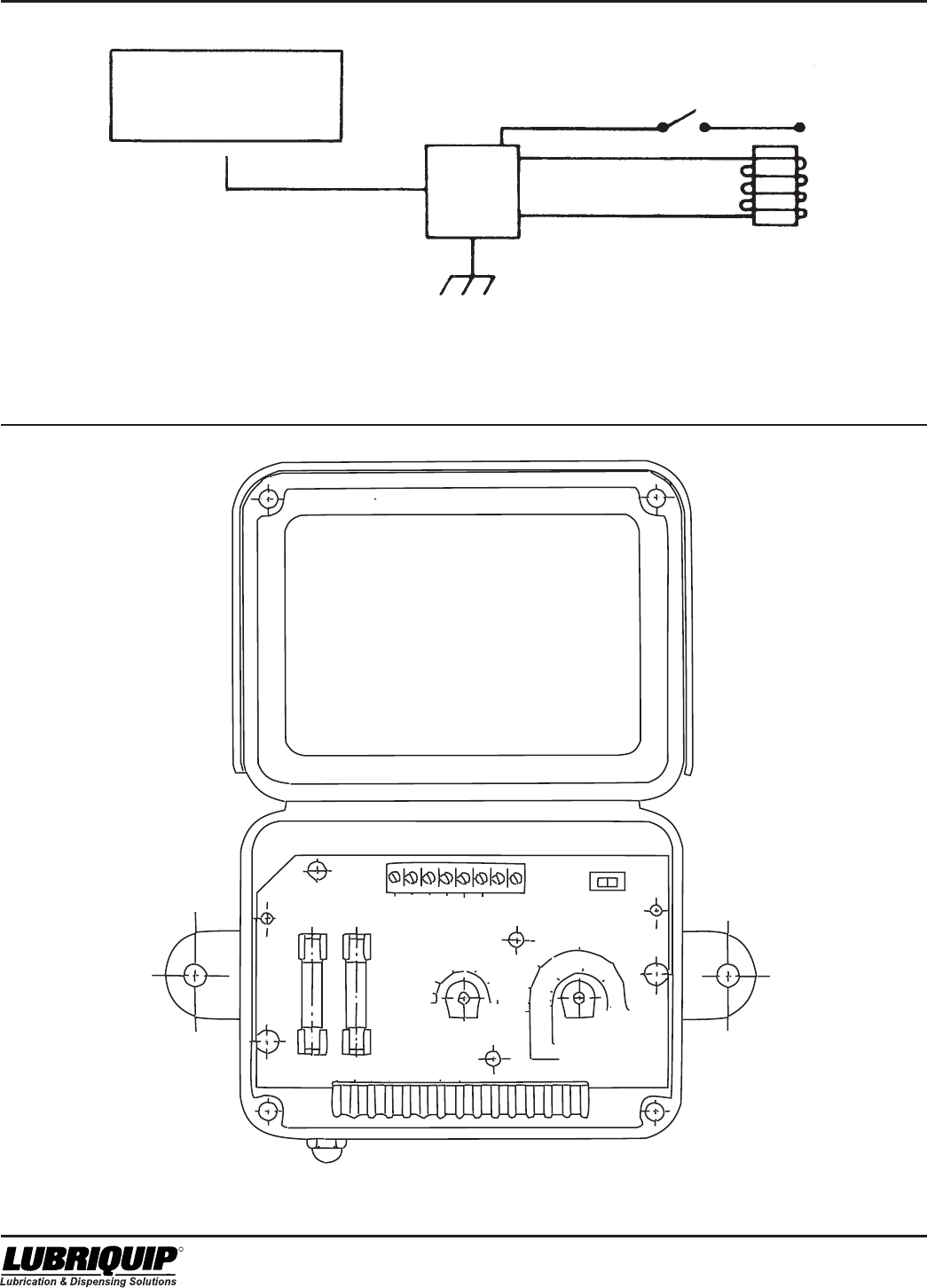
Modu-Flo® System
8-2
42000
R
INSTALLATION INSTRUCTIONS
1. DISCONNECT INPUT AND LOAD POWER SUPPLIES
AT THEIR SOURCE.
2. REMOVE (2) SCREWS AND LIFT OUT CIRCUIT BOARD
3. INSTALL 1/2“ CONDUIT CONNECTOR IN .840
DIAMETER HOLE.
4. CONNECT INPUT POWER LEDS TO INPUT
TERMINALS. 110/220 VAC 50/60 HZ.
5. CONNECT LOAD LEADS TO LOAD TERMINALS.
110/220 VAC 50/60 HZ. 3 AMP MAX.
6. CONNECT REMOTE MANUAL RUN IF DESIRED
(CONTACT ONLY)
7. INSTALL TIMER BOARD WITH (2) =6 X 1/2“ SCREWS
SUPPLIED MAX. TIGHTENING TORQUE 5 IN. LBS.
8. SET TIMER ON AND OFF TIMERS
9. CLOSE AND FASTEN COVER WITH 2 =10 X 3/4“
SCREWS SUPPLIED MAX. TIGHTENING TORQUE 7 IN
LBS AND APPLY POWER.
1/2 AMP
3 AMP
INPUT LOAD
0.2
1
2
57
10
13
ON TIME
MINUTES
CAUTION
DISCONNECT A LOCK
OUT POWER PRIOR
TO SERVICING TO AVOID
POSSIBLE ELECTRICAL
SHOCK.
INPUT
115/230V
50/60 HZ
LOAD
3 AMP
MAX.
MAN
RUN
LOAD ENERGIZED
LUBRIQUIP
TOTAL CYCLE TIME
HOURS
MINUTES
TOTAL CYCLE TIME
MINUTES’ HOURS
5
2
4
8
16
24
32
30
24
16
8
4
2
5
ASSY NO
572-142-590
MANUAL RUN BUTTON
Figure 8-2. AC Timer Wiring Schematic
12 to 32 VDC
POWER SOURCE
ORANGE
(MEMORY)
RED (+)
BLUE (+)
SWITCH
SOLENOIDBLACK
TIMER
GROUND
( – ) ( + )
YELLOW ( – )
Figure 8-1. DC Timer Wiring Schematic
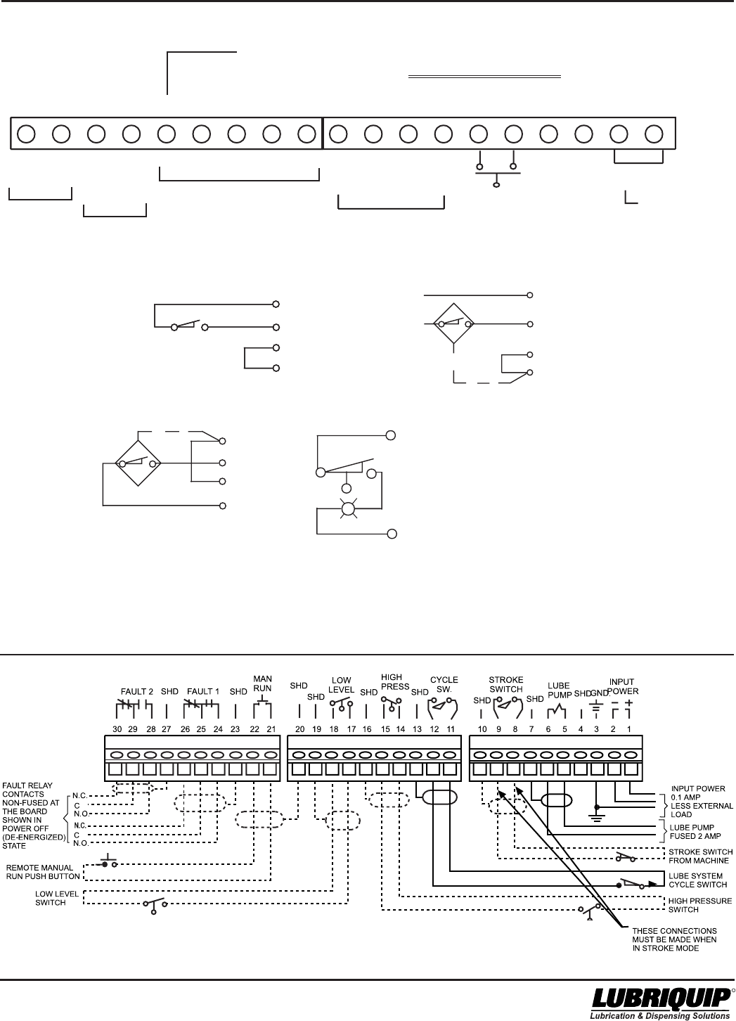
8-3
42000Modu-Flo® System
R
8-3/(8-4 Blank)
Figure 8-3. TC-1000 Timer/Counter Wiring Schematic
Figure 8-4. WMP Maxi-Monitor Wiring Schematic
10
11
12
13
SOURCE SWITCH -
2 OR 3 WIRE TYPE
10
11
12
13
SINK SWITCH -
2 OR 3 WIRE TYPE
10
11
12
13
DRY CONTACT SWITCH
10
11
12
13
SUPPLEMENTAL
WIRING FOR LOW LEVEL
1
2
R
Caution: Voltage will be present at low
level switch and may be
present at lamp when power
to TC-1000 is on
DO NOT USE
HOT
NEU
PUMP
PUMP
1234567
89
MACHINE COUNT
(SEE BELOW)
MANUAL
RUN
SW
SENSE
10 11 12 13 14 15 16 17 18 19
JOG ENABLE
+
-
+
--
+
-
+
-
+
SW IN
SW
-
ADD JUMPER
IF ENABLE
FEATURE IS
NOT USED
CAUTION: INPUT VOLTAGE WILL BE PRESENT ON
TERMINAL - 5 FOR DC MODELS ONLY.
INPUT
OUTPUT

9-1
42000Modu-Flo® System
R
OPERATION AND
SERVICE INSTRUCTIONS
Modu–Flo®
System
SECTION 9
SYSTEM OPERATION
9.1 GENERAL ................................................................. 9-1
9.2 SYSTEM INFORMATION ........................................... 9-1
9.2.1 System Setup ................................................ 9-1
9.2.2 System Filling ................................................ 9-1
9.2.3 System Bleeding ........................................... 9-1
9.2.4 System Start-up ............................................. 9-1
9.3 OPERATING TIPS ..................................................... 9-1
9.3.1 General .......................................................... 9-1
9.4 MATERIAL CONSIDERATIONS ................................. 9-2
9.4.1 Material Cleanliness ..................................... 9-2
9.4.2 Temperature Effects ...................................... 9-2
9.1 GENERAL
9.1.1 This section describes operating procedures for a
Modu-Flo System. Detailed descriptions of the system
components are covered in Sections 1 through 8.
9.2 SYSTEM INFORMATION
9.2.1 System Setup.
9.2.1.1 Before attempting to operate any system, check the
following:
a. Check that the reservoir or tank is securely fastened to
a vertical surface. Make sure that the fill cup or grease-
fill fitting may be easily reached.
b. Check that the manifold is securely connected to the
base of the reservoir or tank. If a remote manifold is
used, make sure it is securely fastened to a vertical
surface, and tubing or hose is connected from the
reservoir to the manifold inlet.
c. Check that the pump is securely fastened to the
manifold.
d. Check all electrical connections to any solenoids,
controllers, level switches or pressure switches used
on the system.
e. Check that all accessories plumbed into the manifold
are secure. Make sure all hose or tubing connections
are tight.
9.2.2 System Filling. The reservoirs or tanks should be
filled as described in Section 2 of this manual. To fill the
remainder of the system, attach a hand pump to the system
fill check valve on the manifold and cycle the hand pump
until the system is filled.
9.2.3 System Bleeding. Proper filling of the system will
reduce the chance of air entrapment. The manifold/pump
assembly still must be bled to remove air which will be
trapped inside the pump. To do this, loosen the setscrew in
the TEST port while the pump is in the dispense stroke.
Tighten the setscrew before the pump reloads. Lubricant
should come out of the vent hole when the pump is dis-
pensing. Cycle the pump several times until air-free
lubricant is dispensed out of the bleed hole, then tighten the
setscrew.
9.2.4 System Start-up. Before starting any system, make
sure that all filling and bleeding steps have been com-
pleted. Refer to Bulletin 30103 for filling and bleeding a
series progressive system. Check the pneumatic or
hydraulic inlet pressure and verify that it is adjusted correctly.
The actual setting will vary from system to system depend-
ing on type of lubricant used and other system variables.
The correct pressure for any particular system will be
determined during initial setup of the system and should not
need to be changed.
9.2.4.1 Check the output of the lubricant pump. Adjust the
output as described in Section 3 of this manual.
9.2.4.2 The system is now ready to run. The pump is
cycled by an external source, such as a timer, counter,
control package, or customer-supplied directional valve.
Once this external source is engaged, the system will cycle
as programmed.
9.3 OPERATING TIPS
9.3.1 General. While the system is operating the
following components may be checked:
9.3.1.1 Check that the pump is cycling according to
schedule. The solenoid or directional valve which operates
the pumps should be actuated by the system controller.
9.3.1.2 Visually check the system for leaks and loose
fittings. Make sure that hoses do not become kinked and
are not rubbing on anything.

Modu-Flo® System
9-2
42000
R
9.3.1.3 If the reservoir or tank is not equipped with low-level
switch, visually check the lubricant level and refill before all
lubricant is used. If the reservoir or tank is allowed to run dry,
air will be introduced into the system, requiring that the
system be bled.
9.4 MATERIAL CONSIDERATIONS
9.4.1 Material Cleanliness. System life and consistent
operation will both be improved by using only clean lubricant.
On all pumps, the lube piston diameter is very close to the
diameter of the chamber in the pump body. Contaminants in
the lubricant could cause scoring in this area, resulting in
erratic pump operation and costly parts replacement. Make
sure that lubricant used to fill the system is clean. If there is
doubt about cleanliness, lubricant should be filtered before
being introduced into the system. After filtering the system,
make sure the lubricant supply is protected from debris. For
protection of divider valves and the equipment being lubri-
cated, an in-line filter (oil) or strainer (grease) should be
installed between this pump and the first stage (master)
divider.
Lubriquip recommends a minimum oil cleanliness level of
ISO 18/14 per ISO standard 4406 for all oil systems.
Lubriquip further recommends that all grease systems be
equipped with a 100 mesh strainer. Refer to bulletin 15200
for available lubricant filters and strainers.
9.4.2 Temperature Effects. Flow characteristics of the
lubricant may change if the area the Modu-Flo system is
used in goes through drastic temperature changes. Choose
a lubricant that will flow properly at all temperatures expected
in the system environment.

10-1
42000Modu-Flo® System
R
OPERATION AND
SERVICE INSTRUCTIONS
Modu–Flo®
System
SECTION 10
TROUBLESHOOTING
10.1 GENERAL ............................................................... 10-1
10.1 GENERAL
10.1.1 Many system problems may be caused by loose
connections or air trapped in the system. Before removing
system components, it is a good practice to check all
connections to make sure they are tight. Also make sure the
system is properly bled. Table 10-1 lists some of the
problems which may occur in the Modu-Flo system along
with possible causes and corrective actions. Disassembly
and assembly procedures for the system components are
contained in other sections of this manual and should be
referred to if a component needs servicing.
Table 10-1. Modu-Flo Troubleshooting
Problem Possible Cause Corrective Action
A. No lube is dispensed 1. Reservoir or tank is empty. 1. Refill as required.
from pump, but pump is
receiving air or hydraulic 2. Air or hydraulic pressure is inadequate. 2. Set pressure to proper setting.
operating signals. 3. If pump is single-acting, return 3. Replace spring or change pump
spring may be defective. to double-acting. (Refer to Section 3.)
4. Pump needs servicing. 4. Disassemble pump and replace
defective components. (Refer to Section 3.)
5. Pump adjustment screw is turned in 5. Adjust pump. (Refer to Section 3.)
too far.
6. Pump is air bound. 6. Bleed air through test port. (Refer to
Figure 4-1).
B. Blow-out disc has ruptured. 1. High pressure exists in the system. 1. Inspect dividers, lines, fittings, and lube
points to determine the source of high pres-
sure. Correct problem and replace disc.
2. Excessive air or hydraulic flow to pump. 2. Install a restrictor in the air or hydraulic
lines.
C. Pump output is erratic. 1. System is not properly bled. 1. Bleed system.
2. Pump needs servicing. 2. Disassemble pump and replace
defective components. (Refer to Section 3.)
3. Pump adjustment assembly is leaking 3. Tighten components of the adjustment
or sucking air during return stroke. assembly.
4. Defective o-ring. 4. Repair pump or manifold. (Refer to
Sections 3 and 4.)
5. Setscrew and ball are loose in TEST 5. Tighten setscrew.
port.

Modu-Flo® System
10-2
42000
R
Table 10-1. Modu-Flo Troubleshooting - Continued
Problem Possible Cause Corrective Action
D. Pump is not receiving 1. Electrical connections to solenoid or 1. Check all connections and tighten
signal to operate. timer are defective. securely.
2. Timer or controller is set incorrectly 2. Set timer or controller to correct
or is defective. setting. If unit is still not functioning consult
factory for assistance.
3. Pneumatic or hydraulic power supply 3. Turn on power supply.
is turned off.

® Registered trademark of LUBRIQUIP, INC.,
Printed in U.S.A.
LUBRIQUIP, INC., 18901 Cranwood Pkwy.
Cleveland, Ohio 44128
Phone: 216-581-2000 or 800-USA-LUBE
FAX: 216-581-8945
R
Bulletin 42000
www.lubriquip.com/pdf/42000.pdf
Trabon® Modu-Flo® System
ISO 9001
REGISTERED FIRM
ISO 14001
REGISTERED FIRM
.cnI,PIUQIRBULotkooL
ruoyfollarof
sdeenmetsySnoitacirbuLdezilartneC
.
:edulcnistcudorP
SEVLAVREDIVID ...ISP0057ot...esaergdnaliorof:
004otpu...ylbmessaevlavelgnisamrofstniop
02ot1
smetsysro...tiucricseiradnoceS/retsaMamorfstniop
.tnalperitnenaeldnahtaht
SPMUP dnalaunam...tnemeca
lpsidelbairavdnadexif:
.nevirdyllacinahcemrorotomcirtcele,cialuardyh,ria
:SLORTNOCCITAMOTUA/SREMIT ffo/n
oelpmismorf
ro-remitrehtie,gnirotinomerusserpdnawolfetelpmocot
.detautca-enihcam
:SEVLAVYROSSECCA .wolfdn
akcehc,gnicnalab
:SROTACIDNI .enilnekorbdnaecnamrofrep
SEIROSSECCA sretlif,spmalc,stekcarb,sgnittif:
sreni
ratsdna
