Grandstream Networks GVR3550 Network Video Recorder User Manual Grandstream
Grandstream Networks, Inc. Network Video Recorder Grandstream
User Manual

www.grandstream.cn
Grandstream Networks, Inc.
GVR3550 Network Video Recorder

GVR3550 USER MANUAL
Grandstream Networks, Inc. GVR3550 User Manual Page 1 of 76
Firmware Version 1.0.0.0 Last Updated: 10/2013
Table of Contents
GVR3550 User Manual
CHNGEE LOG ................................................................................................................ 7
FIRMWARE VERSION 1.0.0.33 .................................................................................................................. 7
FIRMWARE VERSION 1.0.0.33 .................................................................................................................. 7
WELCOME ................................................................................................................. 8
PRODUCT FEATURES ................................................................................................................................ 8
SAFETY COMPLIANCE............................................................................................................................... 9
WARRANTY .............................................................................................................................................. 10
INSTALL GVR3550 ................................................................................................... 11
EQUIPMENT PACKAGE CONTENTS ........................................................................................................ 11
DEVICE CONNECTION ............................................................................................................................. 14
INSTALLING HDD .......................................................................................................................... 14
ROUTE CONNECTION ................................................................................................................... 15
NETWORK CONNECTION ............................................................................................................ 16
EXTERNAL USB DEVICE.............................................................................................................. 17
CONNECT HDMI MONITOR(TBD) .............................................................................................. 18
CONNECT VGA MONITOR ........................................................................................................... 18
CONNECT ALARM DEVICE ......................................................................................................... 18
EXTERNAL INTERCOM DEVICE (TBD) ..................................................................................... 18
GET TO KNOW THE GVR3550 ............................................................................. 19
SOFTWARE SPECIFICATIONS ................................................................................................................. 19
HARDWARE SPECIFICATIONS ................................................................................................................ 20
IR REMOTE CONTROL OPERATIONS ..................................................................................................... 21
USB MOUSE AND KEYBOARD ................................................................................................................. 23
INPUT METHOD ...................................................................................................................................... 23
USING THE WIZARD(TBD) ................................................................................................................ 25
LOGIN ....................................................................................................................................................... 25
LOCAL PREVIEW ..................................................................................................................................... 25
PREVIEW STATUS .......................................................................................................................... 26
BASIC PREVIEW OPERATION ..................................................................................................... 27
IMAGE CONFIGURATION ............................................................................................................ 28
USE PTZ ........................................................................................................................................... 29
RIGHT-CLICK .................................................................................................................................. 31
SHORTCUT BUTTON ..................................................................................................................... 32

GVR3550 USER MANUAL
Grandstream Networks, Inc. GVR3550 User Manual Page 2 of 76
Firmware Version 1.0.0.0 Last Updated: 10/2013
LOCAL PLAYBACK .................................................................................................................................... 32
SEARCH RECORD .......................................................................................................................... 32
RECORD PLAYBACK..................................................................................................................... 34
MAIN MENU ............................................................................................................................................. 36
RECORD CONFIGURATION ......................................................................................................... 36
CHANNEL MANAGEMENT .......................................................................................................... 39
ALARM CONFIGURATION ........................................................................................................... 42
NETWORK SETTINGS ................................................................................................................... 44
STATUS ............................................................................................................................................ 47
SYSTEM SETTINGS ....................................................................................................................... 49
MAINTENANCE .............................................................................................................................. 54
LOGOUT .................................................................................................................................................... 60
WEB MANAGEMENT ............................................................................................ 61
OVERVIEW ............................................................................................................................................... 61
SYSTEM LOGIN ........................................................................................................................................ 61
WEB PAGE INTRODUCTION ................................................................................................................... 62
LIVE PREVIEW ............................................................................................................................... 62
PLAYBACK ...................................................................................................................................... 64
SETTINGS ........................................................................................................................................ 64
FIRMWARE UPDATE ............................................................................................ 65
DOWNLOAD CONFIGURATION FILE ...................................................................................................... 65
CONFIGURING SERVER ........................................................................................................................... 65
CONFIGURING TFTP SERVER ................................................................................................................. 66
CONFIGURING HTTP SERVER ................................................................................................................ 68
UPDATE WITH TFTP SERVER................................................................................................................. 69
UPDATE WITH HTTP/HTTPS SERVER .................................................................................................. 69
MANUAL UPDATE .................................................................................................................................... 69
FACTORY RESET ................................................................................................... 70
RESET VIA LOCAL GUI ............................................................................................................................ 70
RESET VIA WEB PAGE ............................................................................................................................. 70
RESET VIA BUTTON ................................................................................................................................ 70
EXPERIENCING GVR3550 .................................................................................... 71
APPENDIX ................................................................................................................ 71
FAQs .......................................................................................................................................................... 71
MAINTENANCE ........................................................................................................................................ 75
RECORD TIME CALCULATION ................................................................................................................ 75

GVR3550 USER MANUAL
Grandstream Networks, Inc. GVR3550 User Manual Page 3 of 76
Firmware Version 1.0.0.0 Last Updated: 10/2013
Table of Contents
GVR3550 User Manual
Figure 1 : GVR3550 Front Panel ...........................................................................................................12
Figure 2 : GVR3550 Back Panel Specifications ...............................................................................13
Figure 3 : GVR3550 HDD Installation Procedures ..........................................................................15
Figure 4 : GVR3550 Route Connection ...............................................................................................16
Figure 5 : GVR3550 Network Information .......................................................................................16
Figure 6 : GVR3550 USB Access Status ...............................................................................................17
Figure 7 : GVR3550 HDD Management ............................................................................................17
Figure 8 : GVR3550 IR Remote Control ..............................................................................................21
Figure 9 : GVR3550 Soft Keyboard---English Input Method .......................................................23
Figure 10 : GVR3550 Soft Keyboard---Chinese Input Method ....................................................24
Figure 11 : GVR3550 Soft Keyboard---Symbols and Numbers ...................................................24
Figure 12 : GVR3550 Soft Keyboard---- Numeric Keyboard .......................................................24
Figure 13 : GVR3550 Live View Page---Right-click Menu ............................................................25
Figure 14 : GVR3550 Local Login Page ..............................................................................................25
Figure 15 : GVR3550 Abnormal Alarm Prompt ..............................................................................27
Figure 16 : GVR3550 Basic Preview Operations ............................................................................27
Figure 17 : GVR3550 Image Configuration Page ............................................................................28
Figure 18 : GVR3550 PTZ Control Page .............................................................................................29
Figure 19 : GVR3550 PTZ Control Page---Preset ............................................................................30
Figure 20 : GVR3550 PTZ Control Page---Patrol .............................................................................30
Figure 21 : GVR3550 PTZ Control Page---Contrail .........................................................................31
Figure 22 : GVR3550 Right-mouse Menu ..........................................................................................31
Figure 23 : GVR3550 Preview Page Shortcut Button ....................................................................32
Figure 24 : GVR3550 Record Playback Page ....................................................................................32
Figure 25 : GVR3550 Record Playback - Record Status Toolbar ................................................33
Figure 26 : GVR3550 Record Playback Page- Search by Tag .......................................................34
Figure 27 : GVR3550 Tag Management Page ...................................................................................34
Figure 28 : GVR3550 Record Playback Toolbar ..............................................................................34
Figure 29 : GVR3550 Save Snapshot Failed Prompt ......................................................................35
Figure 30 : GVR3550 Tagging Management ...................................................................................35
Figure 31 : GVR3550 Locked Record Management .....................................................................36
Figure 32 : GVR3550 Record Save Path Settings Page ..................................................................36
Figure 33 : GVR3550 Main Menu Page ...............................................................................................36
Figure 34 : GVR3550 Record Channel Settings Page .....................................................................37
Figure 35 : GVR3550 Record Plan Settings Page .............................................................................37

GVR3550 USER MANUAL
Grandstream Networks, Inc. GVR3550 User Manual Page 4 of 76
Firmware Version 1.0.0.0 Last Updated: 10/2013
Figure 36 : GVR3550 Add New Record Plan Page .........................................................................37
Figure 37 : GVR3550 Add New Record Plan Page---Duplicate Time Interval .......................38
Figure 38 : GVR3550 Record Plan Display Page ..............................................................................38
Figure 39 : GVR3550 Record Policy Configuration Page .............................................................38
Figure 40 : GVR3550 Channel Config Page .......................................................................................39
Figure 41 : GVR3550 Manual Add Channel .......................................................................................39
Figure 42 : GVR3550 Encoding Config ...............................................................................................40
Figure 43 : GVR3550 IPC Event Config Page .....................................................................................41
Figure 44 : GVR3550 IPC Arming Time Settings Page ..................................................................41
Figure 45 : GVR3550 IO Alarm Config Page ......................................................................................43
Figure 46 : GVR3550 IO Alarm Config Page ......................................................................................43
Figure 47 : GVR3550 Abnormal Alarm Settings Page ...................................................................43
Figure 48 : GVR3550 Network Settings---Basic Setting ................................................................44
Figure 49 : GVR3550 Advanced Settings ...........................................................................................45
Figure 50 : GVR3550 UPnP Settings ....................................................................................................45
Figure 51 : GVR3550 Server Settings Page .......................................................................................46
Figure 52 : GVR3550 System Information ......................................................................................48
Figure 53 : GVR3550 Network Status ..................................................................................................48
Figure 54 : GVR3550 HDD INFO ...........................................................................................................48
Figure 55 : GVR3550 Device Status Page ...........................................................................................48
Figure 56 : GVR3550 Basic System Settings .....................................................................................49
Figure 57 : GVR3550 Display Settings Page ......................................................................................50
Figure 58 : GVR3550 Local View Control ..........................................................................................50
Figure 59 : GVR3550 Local View Control--- Channel Application .............................................51
Figure 60 : GVR3550 HDD Management ...........................................................................................51
Figure 61 : GVR3550 Property Editing Page ..................................................................................52
Figure 62 : GVR3550 User Management Page .................................................................................52
Figure 63 : GVR3550 Add a User ..........................................................................................................52
Figure 64 : GVR3550 Editing User Info Page .................................................................................53
Figure 65 : GVR3550 Editing Normal User Info Page .................................................................53
Figure 66 : GVR3550 Editing Operator User Info Page ..............................................................53
Figure 67 : GVR3550 S.M.A.R.T Detection Page ..............................................................................55
Figure 68 : GVR3550 HDD Bad Sector Detection Page .................................................................56
Figure 69 : GVR3550 System Log Page ...............................................................................................56
Figure 70 : GVR3550 Record Backup Page .......................................................................................57
Figure 71 : GVR3550 Quick Backup Page .........................................................................................57
Figure 72 : GVR3550 Quick Backup Progress ...............................................................................57
Figure 73 : GVR3550 Search Backup Page ........................................................................................58
Figure 74 : GVR3550 Import/Export Configuration File ...........................................................59
Figure 75 : GVR3550 Update Configuration Page ...........................................................................59
Figure 76 : GVR3550 Upgrade Status Page ........................................................................................60

GVR3550 USER MANUAL
Grandstream Networks, Inc. GVR3550 User Manual Page 5 of 76
Firmware Version 1.0.0.0 Last Updated: 10/2013
Figure 77 : GVR3550 Factory Reset Page ..........................................................................................60
Figure 78 : GVR3550 Web Page---Login ..........................................................................................61
Figure 79 : GVR3550 Web Page--- System Menu ............................................................................62
Figure 80 : GVR3550 Remote Real-time Preview Page ................................................................62
Figure 81 : GVR3550 Remote Record Preview Window ..............................................................62
Figure 82 : GVR3550 Web Page---Channel Preview ....................................................................63
Figure 83 : GVR3550 Web Page---Record Playback .....................................................................64
Figure 84 : GVR3550 Web Page---Basic Settings Page ..................................................................64
Figure 85 : GVR3550 Web Page- Maintenance Menu ....................................................................65
Figure 86 : TFTP Server Page ................................................................................................................66
Figure 87 : TFTP Dialog ...........................................................................................................................67
Figure 88 : TFTP Server Directory Settings ......................................................................................67
Figure 89 : Confirm Modification .........................................................................................................68
Figure 90 : GVR3550 Remote Manual Upgrade ...............................................................................69
Figure 91 : GVR3550 Factory Reset on Local GUI Page ................................................................70
Figure 92 : GVR3550 Factory Rest on Local Web Page .................................................................70

GVR3550 USER MANUAL
Grandstream Networks, Inc. GVR3550 User Manual Page 6 of 76
Firmware Version 1.0.0.0 Last Updated: 10/2013
TABLE OF TABLES
GVR3550 User Manual
Table 1 : GVR3550 Software Specifications ......................................................................................20
Table 2 : GVR3550 Hardware Specifications ...................................................................................21
Table 3 : GVR3550 Soft Keyboard Specifications ............................................................................24
Table 4 : GVR3550 Preview Channel Status Specifications ..........................................................26
Table 5 : GVR3550 Preview Page Specifications .............................................................................27
Table 6 : GVR3550 Abnormal Alarm Specifications .......................................................................27
Table 7 : GVR3550 PTZ Control Specifications ................................................................................29
Table 8 : GVR3550 Email Settings Parameters Specifications ...................................................47
Table 9 : GVR3550 Network Diagnosis Page.....................................................................................54
Table 10 : GVR3550 Network Diagnosis Specifications ................................................................55
Table 11 : GVR3550 Web Page---Channel Preview Specifications ............................................64

GVR3550 USER MANUAL
Grandstream Networks, Inc. GVR3550 User Manual Page 7 of 76
Firmware Version 1.0.0.0 Last Updated: 10/2013
CHNGEE LOG
Only major new features or major document of the GVR3550 updates are listed here. Minor updates for
corrections or editing are not documented here.
FIRMWARE VERSION 1.0.0.33
Snapshots update.
FIRMWARE VERSION 1.0.0.33
This is the initial version.

GVR3550 USER MANUAL
Grandstream Networks, Inc. GVR3550 User Manual Page 8 of 76
Firmware Version 1.0.0.0 Last Updated: 10/2013
WELCOME
Thank you for purchasing Grandstream GVR3550 NVR. The GVR3550 is a NVR product integrating
multi-channel video preview, playback and intelligent alarm monitoring with epoch-making innovation. It is
equipped with perfect hardware platform and vigorous support system, providing the most advanced network
video monitoring solutions and realizing the live view, instant playback, data locking, file security
application. Integrating the leading performance and function in the NVR field, GVR3550 also features
express installation, easy deployment as well as incomparable reliability.
This user manual is designed to help you to understand how to configure and manage the GVR3550
including advanced settings and operating, such as alarm settings and record settings. In order to help users
to configure and manage GVR3550, the manual also introduce its configuration and update procedures in
details.
PRODUCT FEATURES
Supports up to 24 channel with 720p or 12 channel with 1080p HD realtime record
4 channel synchronous local/remote playback ,supports digital zoom in full screen mood and more
than 16 channel remote synchronous preview
Supports Grandstream GXV36XX series camera and compatible camera with ONVIF version
Auto detecting the LAN IP camera
Customized record: schedule record, alarm record, manual record and auto record
The Grandstream patent power storage system handles outage with flexibility
Auto resumes record after restart caused by outage
The previous-recorded video would be overwritten when HDD full
Perfect security mechanism: access control, alarm event, system logs, HDD encryption
Convenient and efficient search record function by time, event, channel and type
Supports up to simultaneous 16 clients remote access the device
Back mode: USB device, External eSATA device or being stored in network or cloud
1 gigabit Ethernet port, HDMI and VGA interface support local HD preview
Alarm input/output port for extended use
Supports 4 SATA HDDs up to 8TB as well as RAID 0, RAID 1 and RAID 10

GVR3550 USER MANUAL
Grandstream Networks, Inc. GVR3550 User Manual Page 9 of 76
Firmware Version 1.0.0.0 Last Updated: 10/2013
SAFETY COMPLIANCE
These instructions are intended to assist users with the operation of the GVR3550 and to instruct on how to
avoid dangerous situations or damage to the device.
Warning: Serious injury or death may be caused if any of the warnings below are neglected.
Caution: Injury or damage to the equipment may occur if any of the following caution messages are
neglected.
Warning: Follow these safe guards to prevent serious injury death.
Caution: Follow these precautions
to
prevent potential injury or
material damage.
Warning:
Input voltage should meet both the SELV(Safety Extra-Low Voltage) and the Limited Power Source with
DC12V according to the IEC60950-1 standard. Please refer to the technical specifications for more details.
Do not use a third-party power adapter or power cord. When the device installed on the wall or ceiling,
make sure that it is firmly attached.
Notice
:
Please ensure stable grounding condition so as to avoid video and audio signal
interference as well as being damaged by static electricity or induced voltage.
Please do not electrify plug the audio/video cables and RS 232; otherwise these ports
can be easily damaged.
Please do not turn off the GVR power switch directly, use the shutdown button on the
front panel (long hold the button for more than 3 seconds) to enable the device to
switch off automatically so as not to damage HDD.
Keep hot reservoir and high temperature environment away from the GVR.
Ensure unit is installed in a well-ventilated environment to facilitate heat dissipation.
Please carry out inspections and maintenance at regular intervals.

GVR3550 USER MANUAL
Grandstream Networks, Inc. GVR3550 User Manual Page 10 of 76
Firmware Version 1.0.0.0 Last Updated: 10/2013
WARRANTY
If the GVR3550 was purchased from a reseller, please contact the company where the device was purchased
for replacement, repair or refund.
If the device was purchased directly from Grandstream, please contact our technical support team for a RMA
(Return Materials Authorization) number before the product is returned.
Grandstream reserves the right to remedy warranty policy without prior notification.
FCC Caution:
Any Changes or modifications not expressly approved by the party responsible for compliance could void
the user's authority to operate the equipment. This device complies with part 15 of the FCC Rules. Operation
is subject to the following two conditions: (1) This device may not cause harmful interference, and (2) this
device must accept any interference received, including interference that may cause undesired operation.
Note: This equipment has been tested and found to comply with the limits for a Class B digital device,
pursuant to part 15 of the FCC Rules. These limits are designed to provide reasonable protection against
harmful interference in a residential installation. This equipment generates uses and can radiate radio
frequency energy and, if not installed and used in accordance with the instructions, may cause harmful
interference to radio communications. However, there is no guarantee that interference will not occur in a
particular installation. If this equipment does cause harmful interference to radio or television reception,
which can be determined by turning the equipment off and on, the user is encouraged to try to correct the
interference by one or more of the following measures:
—Reorient or relocate the receiving antenna.
—Increase the separation between the equipment and receiver.
—Connect the equipment into an outlet on a circuit different from that to which the receiver is connected.
—Consult the dealer or an experienced radio/TV technician for help.
Caution:
Changes or modifications to this product not expressly approved by Grandstream, or operation of this
product in any way other than as detailed by this User Manual, could void your manufacturer warranty.
Please do not use a different power adaptor with the GVR3550 as it may cause damage to the products and
void the manufacturer warranty.
Reproduction or transmittal of the entire or any part, in any form or by any means, electronic or print, for
any purpose is not permitted without the express written permission of Grandstream Networks, Inc.

GVR3550 USER MANUAL
Grandstream Networks, Inc. GVR3550 User Manual Page 11 of 76
Firmware Version 1.0.0.0 Last Updated: 10/2013
INSTALL GVR3550
EQUIPMENT PACKAGE CONTENTS
The GXV3550 package contains:
One(1) Main Case
One(1) 12V Power Adaptor
One(1) Power Cord
One(1) Ethernet Cable
One(1) Remote Control(No Battery )
Sixteen (16)Screws
Four (4) SATA HD
Two (2) A two power line
One (1) Quick Start Guide
To set up a set of GVR, users need to own some equipment listed below:
One (1) Display device (It could be the monitor, displayer or TV wall, choose one of them at least)
At least one (1) Video Acquisition Processing Equipment (Camera combined with encoder or IP
camera device)
Optional keyboard with USB interface
Optional mouse with USB interface
At least one (1) HDD (Compatible SATA is required. The maximum CAPACITY is no more than
2T.)
Optional Audio Devices (Audio input and output devices: acoustics, microphone or pickups, etc.)
Optional Alarm Devices (Alarm input and output devices: smoke detector, infrared detector and
alarm bell, etc.)
GVR3550 USER MANUAL
Grandstream Networks, Inc. GVR3550 User Manual Page 12 of 76
Firmware Version 1.0.0.0 Last Updated: 10/2013
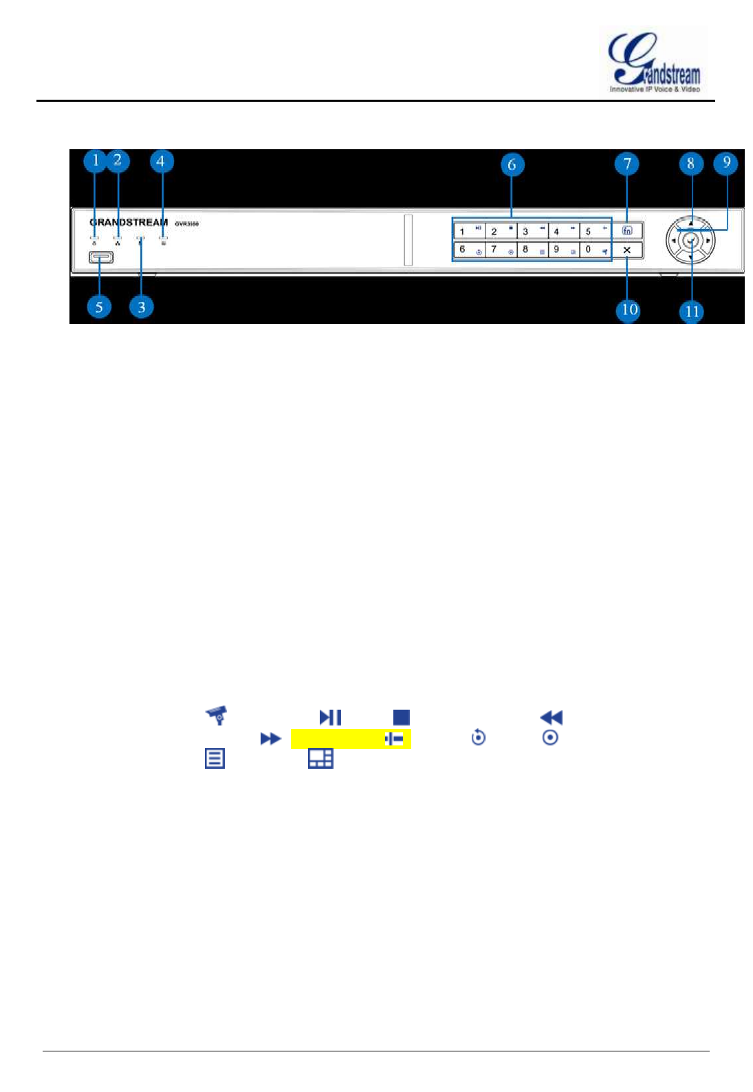
Figure 1: GVR3550 Front Panel
1.
Power indicator
Power indicator
2.
Network Indicator
When the network is abnormal or the GVR has no access to
network, the indicator doesn’t flicker when alarm; the indicator
turns red when the network connection is normal and flickers
green when there is a network data transmission.
3.
HDD Indicator
The indicator turns red to alarm if HDD is abnormal or the HDD
capacity is lower than one certain value. The indicator is green
when HDD runs normally.
4.
Status Indicator
Used to indicate whether the numeric buttons are in other
functional mode. Once being pressed, the numeric buttons will
be used in other functions. The indicator turns green when the
numeric buttons are in functional mode while in numeric mode
the indicator is dark.
5.
USB Interface
Used to connect to USE device like mouse, keyboard and USB
flash drive.
6.
Numeric/
Function Buttons
Used to input numbers. Once the function buttons are pressed,
the numeric buttons will be used as function buttons. Number 0-9
are corresponding to the following function: Enable PTZ
,Start/Pause ,Stop ,Fast Backward ,Fast
Forward ,Single Frame ,Playback ,Record ,Menu
,Multiscreen .
7.
Function Buttons
Used to switch between numeric buttons and function buttons.
The function buttons status will be indicated by the function
status indicator.
8.
Up and Down
Direction Buttons
Used to switch the activated controls or move/skip up or down,
revise setting ,add or subtract numbers.
Auxiliary Function: Navigate the PTZ menu up or down
9.
Left and Right
Direction Buttons
Used to switch the activated controls or move/skip left or right
Controls the progress bar when playback.
Auxiliary Function: Navigate the PTZ menu left or right.
GVR3550 USER MANUAL
Grandstream Networks, Inc. GVR3550 User Manual Page 13 of 76
Firmware Version 1.0.0.0 Last Updated: 10/2013
10.
Cancel Button
Back to the previous menu or cancel operation.
Back to realtime monitoring state when playback.
11.
Confirm Button
Confirm
Switch to the default button
Enter menu
Switch between checkbox and ON/OFF button
Pause/Restore auto patrol in the auto patrol preview mode
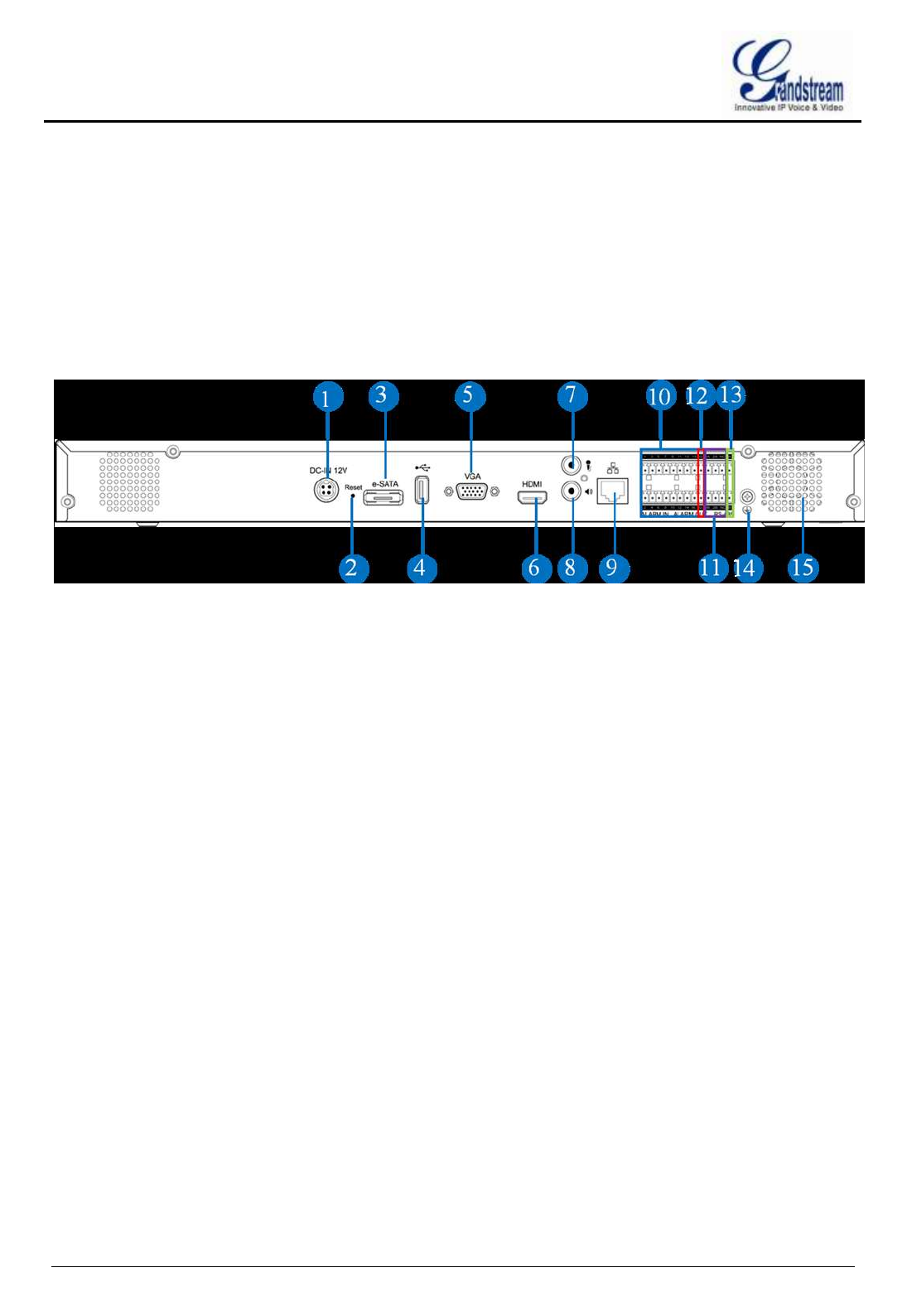
Figure 2: GVR3550 Back Panel Specifications
1.
Power Input Interface
Power interface, input 12V DC.
2.
Reset Button
Used to reboot device or reset factory
Press: Reboot
Long press for more than 10 seconds: factory reset
Press when powered on: reset when the unit is abnormal.
3.
eSATA Interface
Used to connect eSATA
4.
USB Interface
Used to connect to USB devices like mouse, keyboard and
USB flash drive.
5.
VGA Video Out
Output analog video signal, could be connected to a
monitor to view the analog video.
6.
HDMI Interface
HAD and HD video output interface, transmit
uncompressed HD video and multi-channel audio data to
the display device with HDMI interface.
7.
Audio Input Interface
Voice intercom input interface, receive analog audio signal
from microphone, pickups and other equipment.
8.
Audio Output Interface
Output analog audio signal to device like speakers.
9.
Network Interface:
10M/100M/1000M adaptive Ethernet interface, connect
cables.

GVR3550 USER MANUAL
Grandstream Networks, Inc. GVR3550 User Manual Page 14 of 76
Firmware Version 1.0.0.0 Last Updated: 10/2013
10.
Alarm Input Interface
1
~
16:
16 alarm input interface, receiving binary signals of
external alarm like Normally-closed alarm and
normally-open alarm.
When applying the external power to electrify the alarm
input device, the latter should be common-grounded with
the GVR.
11.
Alarm output Interface
1
~
2:
2 sets alarm output interface, output alarm signal to the
external alarm device, power supply is required for
external alarm device.
12.
Alarm Grounding
Interface:
Public alarm input grounding interface
13.
Grounding:
Grounding
14.
FAN:
Used for heat dissipation
DEVICE CONNECTION
The GVR3550 contains no HDD with packaging, users need to check the device and install HDD when use it
the first time.
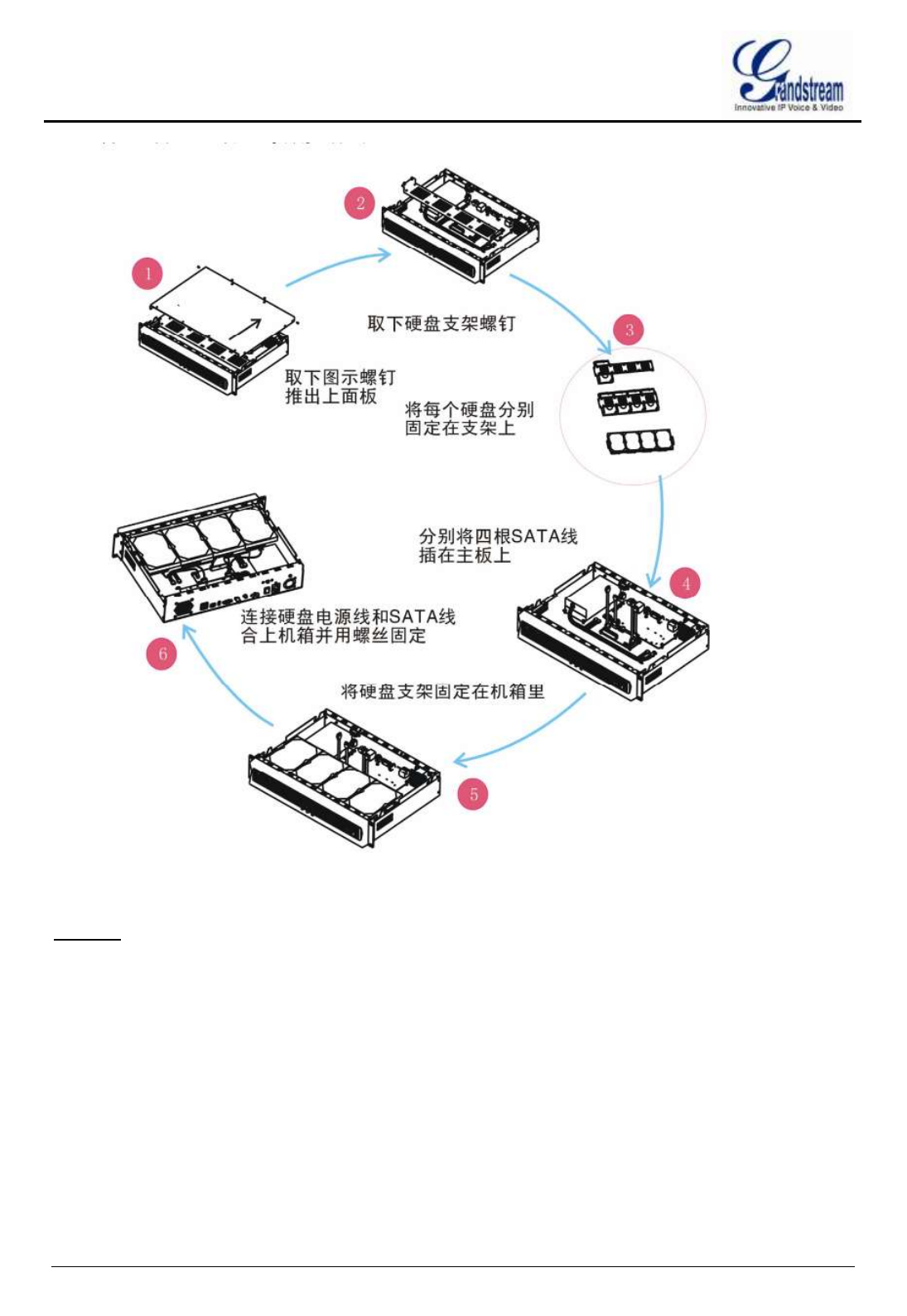
INSTALLING HDD
We suggest to use the recommended models by Grandstream( 7200 RPM HDD and above), the PC HDD is
not recommended.
Please install the GVR3550 HDD according to the following procedures:
1. Twist four screws gently on the bottom of the HDD, don’t twist too tight.
2. Remove the fixed screws on the back and side panel of the device, open the cover plate to find the HDD
installing position.
3. Side put the main case, Aim the HDD with four screws at the corresponding round holes on the baseplate
then push the screws to the screw holes to stick them.
4. Twist the screws.
5. Repeat the previous steps to install other HDDs(install one HDD next to the other with connected HDD
cables ).
6. Plug in four HDD cables and power cables to the interfaces of the mainboard .
7. Put the cover plate back to GVR and twist the screws.
GVR3550 USER MANUAL
Grandstream Networks, Inc. GVR3550 User Manual Page 15 of 76
Firmware Version 1.0.0.0 Last Updated: 10/2013
Figure 3: GVR3550 HDD Installation Procedures
NOTE:
HDD does not support hot plug. When the GVR3550 is running, plug the HDD will result in the
HDD read and write data errors or unable to identify. Grandstream will take no responsibility for
the damage.
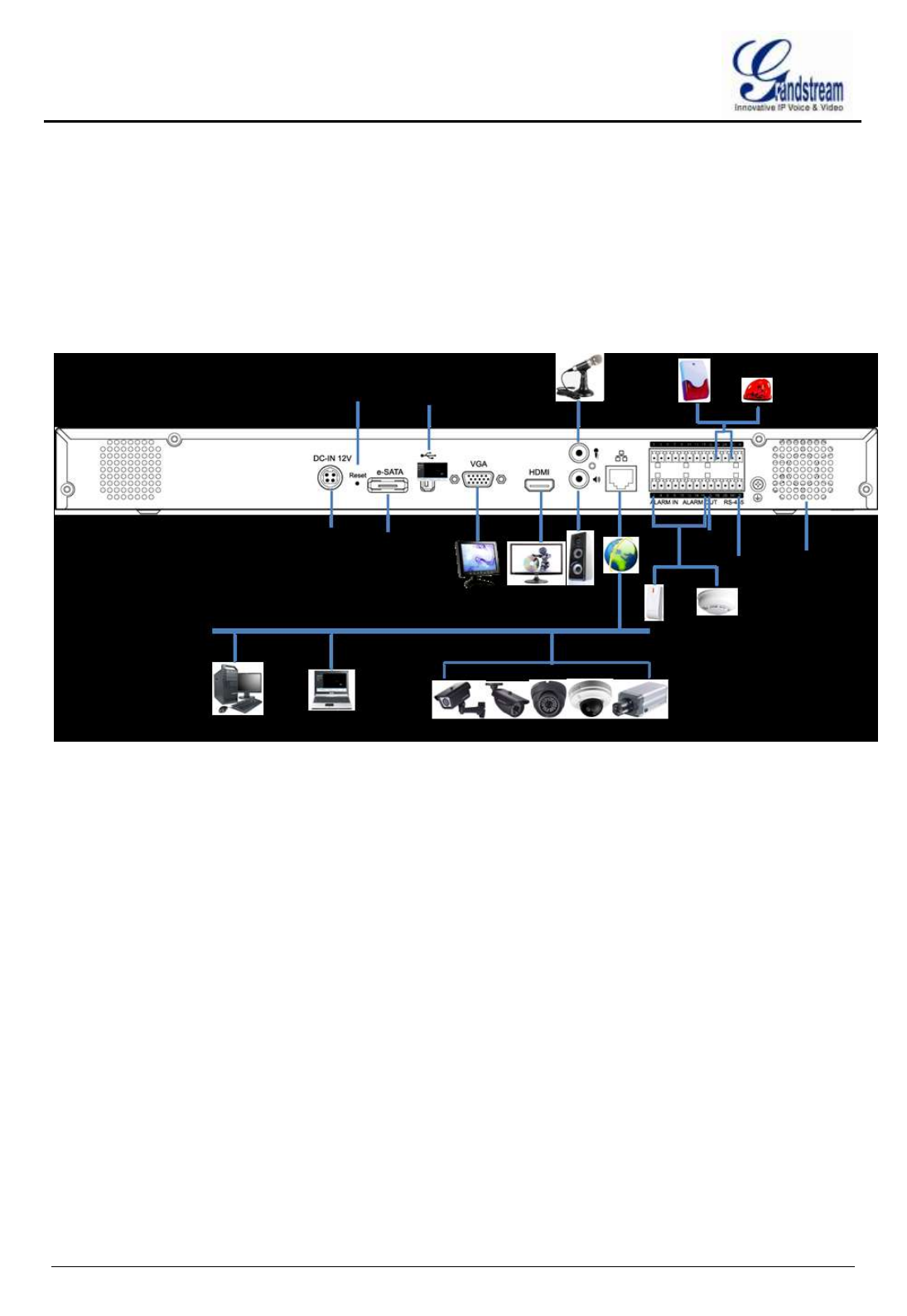
ROUTE CONNECTION
Please connect the GVR3550 route according to the following procedures:
1. Install the GVR3550 HDD by reference to the steps in installing HDD procedures.
GVR3550 USER MANUAL
Grandstream Networks, Inc. GVR3550 User Manual Page 16 of 76
Firmware Version 1.0.0.0 Last Updated: 10/2013
2. Install the cables and connect to the display device interface.
3. Connect the mouse, keyboard, alarm input and output devices (optional).
4. Power on the related devices(GVR3550, display device, alarm, etc.) after connecting to the power cable.
5. The GVR3550 is about to power up and the indicators flickers.
6. When all devices have been powered on successfully, the connection has been completed.
GVR3550 route connection is shown in figure 4:
Figure 4: GVR3550 Route Connection
NETWORK CONNECTION
Users could login the local page with the administrator account after connecting the network cable to the
GVR3550, go to Main Menu ->System Information -> Network Information to check the network
connection status including IP address and network send/receive rate as shown in figure 5. For details, please
refer to the chapter “Network Information”.
Figure 5: GVR3550 Network Information

GVR3550 USER MANUAL
Grandstream Networks, Inc. GVR3550 User Manual Page 17 of 76
Firmware Version 1.0.0.0 Last Updated: 10/2013
EXTERNAL USB DEVICE
GVR3550 USB interface could be used to connect the mouse and keyboard, or connect a USB storage
device.
NOTE:
The voltage of the USB interface on the front panel of the GVR3550 is a little higher than the one on
the the rear panel, it is suggested that the USB interface on the rear panel connect to USB mouse
and keyboard while the one on the front panel connect to USB storage devices.
PLUG INTO USB MOUSE/KEYBOARD
Users could manipulate the mouse and keyboard to test whether the installation is successful or not after
plugging them into the GVR3550. The mouse or keyboard might be not compatible with GVR3550 if can't
be detected, please replace the mouse or keyboard and try again.
PLUG INTO USB STORAGE DEVICE
Users could go to Maintenance->Network Diagnosis, select “Refresh” in “Packet Capture ” entry to check
the USB status after inserting the USB storage device into the interface properly.
Figure 6: GVR3550 USB Access Status
INSTALLING eSATA
Inset the eSATA cable to the corresponding interface on the rear panel of the GVR3550, Power up eSATA
or use USB cable to supply power (the connection mode is in accordance with eSATA specification).Users
could go to Main Menu->System Settings->HDD Management to view details like HDD Space,Free Space,
HDD Status, HDD Type and so on after installing eSATA. For details, please refer to the chapter “HDD
Management”.
Figure 7: GVR3550 HDD Management

GVR3550 USER MANUAL
Grandstream Networks, Inc. GVR3550 User Manual Page 18 of 76
Firmware Version 1.0.0.0 Last Updated: 10/2013
CONNECT HDMI MONITOR(TBD)
Connect one end of the HDMI cable to the port on the rear panel of the GVR3550, and the other end to the
corresponding port of the HDMI monitor. Once powered on, a splash screen appears on the monitor.
GVR3550 can automatically adapt to HDMI monitor with 1080p and 720p resolution.
CONNECT VGA MONITOR
Connect one end of the VGA cable to the port on the rear panel of the GVR3550, and the other end to the
corresponding port of the VGA monitor. Once powered on, a splash screen appears on the monitor.
NOTE:
VGA doesn’t support automatic resolution matching.
There is only one valid output when connected with VGA and HDMI monitor at the same time. On
this occasion, HDMI is valid while VGA is not by default. Users can also go to System
Settings->Display to set parameters like Screen Resolution, Brightness,Contrast,Saturation and
Hue.
CONNECT ALARM DEVICE
Alarm input/output device connection procedures are as follows:
1. Connect the alarm input device to the alarm input port.
2. Connect the alarm output device to the alarm output port.
3. Enter the GVR3550 main menu, make corresponding settings to alarm input/output on the Alarm Settings
page. Alarm serial number 1 corresponds to the first alarm input channel on the GVR3550 I / 0 port.The
following numbers keep to the same matching sequence. Set normally-opened alarm and
normally-closed alarm according to the corresponding generated high /low level input when there is an
alarm.
4. Set alarm output on the Alarm Settings page. Alarm output 1 corresponds to the first alarm output channel
on the GVR3550.The following numbers keep to the same matching sequence.
EXTERNAL INTERCOM DEVICE (TBD)

GVR3550 USER MANUAL
Grandstream Networks, Inc. GVR3550 User Manual Page 19 of 76
Firmware Version 1.0.0.0 Last Updated: 10/2013
GET TO KNOW THE GVR3550
SOFTWARE SPECIFICATIONS
Name
Specifications
Video Record
Supports synchronous 24 channel 720p (with 1280x720 resolution)
record or 6 channel 1080p (with 1920x1080 resolution) record
Record Rate
Supports a maximum of 48 Mbps record rate
Record Mode
Supports Continuous Record, Scheduled Record, Alarm Record and
Manual Record
Video
Encoding
H. 264 baseline, main or higher.
Video
Encoding
synchronous Audio & Video record
Audio
Encoding
G.711, G.726
Live View
Supports synchronous HDMI or VGA 4 channel 720p or 2 channel
1080p output
Up to synchronous 16 channel remote live view
Playback
Supports synchronous local or remote 4 channel video playback.
Trigger Event
Alarm
Trigger modes: Manual Alarm, Scheduled Alarm, IPC alarm, I/O alarm,
Event Alarm and Abnormal Alarm
Intelligent Retr
ieval
Intelligent retrieval modes: Retrieval by Date & Time, Motion Detection,
Missing Object Detection, Foreign Object detection,Camera Lens
Occlusion, Video Loss, ect.
Storage
Supports up to 8 TB encrypted storage
RAID
RAID
Supports RAID 0, RAID 1 or RAID 10
Redundancy
Supports record backup to USB,eSATA or network backup
QoS
Supports Diff-Serv, TOS, 802.1P/Q VLAN tagging
Protocol
Supports HTTP, HTTPS, ONVIF protocol

GVR3550 USER MANUAL
Grandstream Networks, Inc. GVR3550 User Manual Page 20 of 76
Firmware Version 1.0.0.0 Last Updated: 10/2013
Network
Protocol
Supports TCP/UDP, RTP/RTCP/RTSP, HTTP/HTTPS, ARP, ICMP,
DNS, DDNS, DHCP (client and server), NTP (client and server), SSH,
PPPoE, LLDP, ONVIF 2.2
IPC
Supports the Grandstream GVX36xx or cameras compatible with
ONVIF protocol
Security Proto
col
Supports HTTPS, 802.1x, SSH
Maintenance
Supports manage device via the System Log, Remote Network, SSH
and GSurf Pro
Table 1: GVR3550 Software Specifications
HARDWARE SPECIFICATIONS
Name
Specifications
Interface
1 HDMI interface, 1VGA interface, 1 RJ45 gigabit adaptive Ethernet
interface, 2 RCA audio input &output interfaces
Alarm In
16 NO/NC alarm input interfaces
Alarm Out
1 alarm output interfaces
UPS
Manage UPS via USB or USB serial port
USB Interface
2 2.0 USB interfaces
eSATA
1 eSATA interface
LED Indicator
Power Indicator, Network Status Indicator, HDD Status Indicator,
Keyboard Function Indicator
Remote
Control
Supports IR remote control operation
RTC
Supports RTC
HDD
Supports up to 4 SATA HDDs with a maximum of 8TB storage capacity
in total. The single HDD capacity up to 2 TB
Temperature
Operating Temperature: -10°C -50°C
Storage Temperature: -20°C -60°C
Humidity
10-90% (non-condensing)
Installations
Supports the rack-mounted front installations
Compliance
FCC: Part 15(CFR47)Class B ;UL 60950 (Power)
CE: EN55022 Class B, EN55024, EN61000-3-2, EN61000-3-3,
EN60950-1, RoHS
C-TICK: AS/NZS CISPR22 Class B,AS/NZS CISPR24
GVR3550 USER MANUAL
Grandstream Networks, Inc. GVR3550 User Manual Page 21 of 76
Firmware Version 1.0.0.0 Last Updated: 10/2013
Table 2: GVR3550 Hardware Specifications
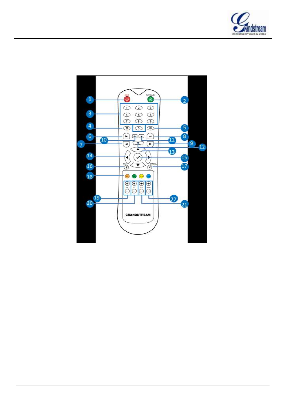
IR REMOTE CONTROL OPERATIONS
Figure 8: GVR3550 IR Remote Control
1.
REC Button:
Manual start/stop record.This button works
in concert with the direction buttons in the record
control menu to select the channel to record
2.
Playback Button:
Enter playback screen
3.
Numeric Buttons:
Function as the numeric buttons on the front panel
4.
MENU Button:
Enter menu
5.
Multiscreen Button:
Switch the monitor screen to a single screen or
multiscreen
6.
Single-frame back Button:
Single frame playback of the record
7.
Single-frame Step Button:
Single frame forward of the record
8.
Fast Backward Button:
Various fast forward and normal playback modes.
The speed would be displayed on the playback screen
9.
Fast Forward Button:
Various fast forward and normal playback modes.The
speed would be displayed on the playback screen
10.
Skip Button:
Switch to Skip mode. The button is used in concert

GVR3550 USER MANUAL
Grandstream Networks, Inc. GVR3550 User Manual Page 22 of 76
Firmware Version 1.0.0.0 Last Updated: 10/2013
with the UP&DOWN buttons to determine since
when to play record.
11.
STOP Button:
Stop playing record
12.
PLAY/PAUSE Button:
Press the button to forward when playback pauses.
Press the button to pause playback when playing
record.
13.
UP&DOWN Direction
Buttons:
Users could press the buttons to switch the activated
programs by switching left or right
Control selecting channels via left & right button
when preview
Control the progress bar when playback record
Auxiliary function (e.g.: Control and operate the PTZ
menu)
14.
Left & Right Direction
Buttons:
Users could press the buttons to switch the activated
programs by switching up or down
Controls selecting channel via up&down buttons
when preview
Auxiliary function (e.g.: Control and operate the PTZ
menu)
15.
ENTER Button:
Press to confirm operations
Press to switch to the default button
16.
PTZ Control Button:
Enable/Disable PTZ Control
17.
Cancel Button:
Exit current menu to the upper level menu or cancel
operations when pressing the function menu button
(Close the top-level page or programs).
18.
Function Buttons 1-4:
19.
Volume+- Button:
Adjust the volume of the video channel or the one in
channel when playback
20.
Aperture+- Button:
Adjust aperture at PTZ control
21.
Focus+- Button:
Adjust focus at PTZ control
22.
Zoom+- Button
Electronic zoom adjustment at PTZ control
Electronic zoom adjustment when single channel
playback at full screen
The correct way to use IR remote control: Batteries must be installed before operation. Please aim the remote
control at the IR receiver on the GVR3550 then make operations. If the GVR3550 receives the control’s
command, you can use the control to manipulate the GVR3550. If failed, please check whether the following
reasons are the causes:
Check the polarities of batteries
Check whether the batteries are used up
Check whether the remote sensor is obscured

GVR3550 USER MANUAL
Grandstream Networks, Inc. GVR3550 User Manual Page 23 of 76
Firmware Version 1.0.0.0 Last Updated: 10/2013
Check whether a fluorescent lamp is being used nearby
If the remote still can’t function properly beyond the above situations, please change a remote and try again,
or contact the device provider.
USB MOUSE AND KEYBOARD
When the USB mouse is plugged into the GVR3550, users could make the following operations with the
mouse:
Single click the left mouse:
Enter a functional menu.
Select one function and enable it.
Bring up the drop-down list when clicking the combo box.
Switch input methods in the input box, click on the corresponding symbol buttons on the soft keyboard to
input numbers.
Double click the left mouse:
Double click on one channel screen to switch to full screen in multi-screen view mode. Double click again to
exit full screen and go back to the previous multi-screen status.
Single click the right mouse:
Bring up the shortcut menu in realtime monitoring mode.
Do not save the setup menu content and exit the current menu, go back to the preview screen.
Scroll wheel:
Scroll up and down the list box.
MouseMove.
Select the entry or move one item of them with cursor.
NOTE:
If in a rare case that the mouse is not detected, the possible reason may be that the mouse is not
compatible with the GVR3550, please replace the mouse.
INPUT METHOD
The GVR3550 supports both English and Chinese input methods, the input interface is as shown below.
Figure 9: GVR3550 Soft Keyboard---English Input Method

GVR3550 USER MANUAL
Grandstream Networks, Inc. GVR3550 User Manual Page 24 of 76
Firmware Version 1.0.0.0 Last Updated: 10/2013
Figure 10: GVR3550 Soft Keyboard---Chinese Input Method
Figure 11: GVR3550 Soft Keyboard---Symbols and Numbers
Figure 12: GVR3550 Soft Keyboard---- Numeric Keyboard
Table 3:
GVR3550 Soft Keyboard Specifications
Input lowercase
Switch Caps Lock
Sigquit
Switch to Numbers & Symbols
Switch to alphabet
Space
Switch to Chinese Input Method
Enter
Backspace

GVR3550 USER MANUAL
Grandstream Networks, Inc. GVR3550 User Manual Page 25 of 76
Firmware Version 1.0.0.0 Last Updated: 10/2013
LOCAL OPERATIONS
In this chapter, we take using the mouse as an example.
USING THE WIZARD(TBD)
When the unit is enabled, users could use the wizard for basic configuration when once start the GVR3550 to
make it work properly.
1. Check the display resolution. Please check the highest resolution the connected monitor supports before
selecting the resolution, make sure the highest resolution you select is no higher than the parameters the
monitor supports.
2. Confirm whether to enable the wizard the next time boot up the unit.
3. Permission authentication.
4. Time configuration. Set Time Zone, Date Format, System Time.
5. Network configuration .Set network parameters like IP Address, Subnet Mask and Gateway.
6. HDD Initialization.
7. Record configuration.
8. Save the changes and return to the wizard page to confirm finishing the setting.
LOGIN
The factory default username is “admin”, the password is “admin”. Users would be required to login again if
timeout without operations on the page. Please change the password after login without delay.
After entering the GVR3550 local interface, it would display the live view interface as shown in figure 13
below.Users could click right mouse and then select any item in a pop-up menu to bring up the GVR3550
login interface. Or click on menu button in the lower left corner to login.
Figure 13: GVR3550 Live View Page---Right-click Menu
Figure 14: GVR3550 Local Login Page
LOCAL PREVIEW
The GVR3550 would directly display Live Preview after boot up, users could check the preview screen
without login but unable to make any operations. Users could only make basic view operations and other
setups after logged in.

GVR3550 USER MANUAL
Grandstream Networks, Inc. GVR3550 User Manual Page 26 of 76
Firmware Version 1.0.0.0 Last Updated: 10/2013
PREVIEW STATUS
Preview channel status: The channel has not been added, channel preview, connecting the channel, channel
connection failed.
Name
Specifications
Add Channel
There is no channel added before. Click this button to
quick enter the Channel Settings interface to add channel.
Channel
Preview
Live view channel screen
Connecting the
channel
Connecting the channel, no screens being played yet.
Channel
connection
failed
Display icon indicates channel connection failed
Table 4: GVR3550 Preview Channel Status Specifications
On the preview page, the record and alarm status of each channel could be distinguished by the tag at the top
right corner of each channel.
Symbol
Name
Specifications
Motion
Detection
Alarm
Alarm when detecting dynamic motion.
Camera
Lens
Occlusion
Alarm
Alarm in the corresponding channel when the remote
camera is obscured.
Missing
Object
Alarm
Alarm in the corresponding channel according to the
alarm settings if the remote camera supports Missing
Object Alarm and Local Missing Object Alarm has been
configured before.
Foreign
Object
Alarm
Alarm in the corresponding channel according to the
alarm settings if the remote camera supports Missing
Object Alarm and Local Foreign Object Alarm has been
configured before.

GVR3550 USER MANUAL
Grandstream Networks, Inc. GVR3550 User Manual Page 27 of 76
Firmware Version 1.0.0.0 Last Updated: 10/2013
I/O Alarm
Alarm when the remote camera is connected to IO alarm
devices according to the alarm settings.
Record
The monitoring channel is in record mode.
Table 5: GVR3550 Preview Page Specifications
A dialog box will pop up in the center screen to prompt the users if there is an abnormal alarm, as shown in
figure 15 below, the prompt box would disappear in 3 seconds.
Figure 15: GVR3550 Abnormal Alarm Prompt
Symbol
Name
Specifications
Disconnecti
on Alarm
Alarm when the network is disconnected
HDD Empty
Alarm
Alarm when no HDD detected
HDD Error
Alarm
Alarm when HDD is abnormal.
HDD Full
Alarm
Alarm when HDD is full.
Alarm when detecting the IP address of the other device
is in conflict with the GVR in the network.
IP Conflict
Alarm
Alarm when detecting the IP address of the other device
is in conflict with the GVR in the network.
Table 6: GVR3550 Abnormal Alarm Specifications
BASIC PREVIEW OPERATION
Users could put the cursor on the channel screen if need to make basic operations to a particular channel.
Click on the screen to bring up the menu bar as shown in figure 16. Click the buttons on the menu bar to
make corresponding operations.
Figure 16: GVR3550 Basic Preview Operations

GVR3550 USER MANUAL
Grandstream Networks, Inc. GVR3550 User Manual Page 28 of 76
Firmware Version 1.0.0.0 Last Updated: 10/2013
REC Off:
The channel is not recording now.
Auto REC:
The channel is in Scheduled Record mode.
Manual
REC:
The channel is in Manual record mode.
Capture:
Capture the preview image and the external storage devices (like USB,
eSATA) need to be connected. Users could configure the save path and
set it to default.
Volume
OFF/On:
If the remote camera is installed with audio input device once the
volume is on, users could listen in to the user whose voice is conveyed
from the remote camera.
Intercom
On/Off:
If the remote camera is installed with audio input device once the
intercom is on, users could speak to the user from the remote camera
via local audio input device.
PTZ
Control :
Click to enable PTZ Control to make basic operations like PTZ preset,
patrol, Pattern, Contrail.
Switch to
full
Screen:
Switch the current screen to full screen or double click to enter full
screen mode. Double click again to exit full screen.
Instant
Replay:
Playback the record in the preset time of the channel. It will prompt
“The selected channel has no record”if there is no record, Users could
set the preset time in the Basic System Settings.
Image
Configurati
on:
Enter Image Configuration page to adjust the current window image.
IMAGE CONFIGURATION
Click on the Image Configuration button to bring up the Image Settings dialogue box as shown in
figure 17.Users could adjust brightness, contrast, saturation and hue by clicking the corresponding
Plus/Minus icon.
Figure 17: GVR3550 Image Configuration Page
NOTE:
The GVR3550 only supports PTZ control with ONVIF Protocol, the IP camera should be properly
connected while the PTZ device should be configured. Please make sure the RS-485 cable between
the PTZ decoder and the IP camera connected correctly.

GVR3550 USER MANUAL
Grandstream Networks, Inc. GVR3550 User Manual Page 29 of 76
Firmware Version 1.0.0.0 Last Updated: 10/2013
USE PTZ
Click the PTZ Control button to bring up the PTZ Control page, as shown in figure 18 below.
Figure 18: GVR3550 PTZ Control Page
Name
Specifications
PTZ Direction
Control and
Reset button
8 PTZ direction buttons are used to control the
corresponding eight directions of PTZ, the reset
button is used to restore PTZ direction to the
original position.
Adjust
Aperture+,
Focus+, Lens +
Zoom in the Aperture, Focus and Lens
respectively. Lens + is only available when the
channel is in full screen mode.
Adjust
Aperture-,
Focus-, Lens -
Zoom out the Aperture, Focus and Lens
respectively. Lens - is only available when the
channel is in full screen mode.
More:
Bring up more PTZ settings.
PZT Control
Selection
Bring up preset setting and operation panel below
the screen when PTZ is set to preset.
Bring up patrol setting and operation panel below
the screen when PTZ is set to patrol.
Bring up pattern setting and operation panel
below the screen when PTZ is set as contrail.
Exit PTZ
Control
Click to exit the PTZ Control panel directly.
Table 7: GVR3550 PTZ Control Specifications

GVR3550 USER MANUAL
Grandstream Networks, Inc. GVR3550 User Manual Page 30 of 76
Firmware Version 1.0.0.0 Last Updated: 10/2013
PRESET
Users could choose PTZ control as preset then make operations like add/delete/edit preset on the control
panel below. The procedures are shown in figure 19.
Figure 19: GVR3550 PTZ Control Page---Preset
1. Adjust the remote camera position via the PTZ direction control.
2. Click on below the preset control panel to add a new preset.
3. Enter the name of preset in the added input box or use the default name.
4. Click the check button on the right to save the preset, or click on the right of the preset to edit the
name.
5. Double click the preset with mouse(or the Confirm button on the front panel , or the Enter button on the
control) to activate it.
6. Once selected the preset, users could click on the button below the preset control panel to cancel the
operation if don’t need it.
PATROL(TBD)
Users could edit and apply patrols on the control panel if set PTZ operation to patrol. The factory default
setting are 4 empty patrol paths. See figure 20.
Figure 20: GVR3550 PTZ Control Page---Patrol
1. Set PTZ control to patrol.
2. Select the patrol path.
3. Set the time duration the patrol path stays at each preset .
4. Click on to add key point and set it as one preset. Users could click on in the lower right corner of
the panel to delete the key point if set the wrong key point.
5. Click on before the patrol path. Once the button turns into a triangle , the PTZ will cycle according to the
path. Click again to stop the patrol.
CONTRAIL(TBD)
Users could edit and apply contrail on the control panel below if set PTZ operation to contrail. The factory
default setting are 3 empty contrails. See figure 21.

GVR3550 USER MANUAL
Grandstream Networks, Inc. GVR3550 User Manual Page 31 of 76
Firmware Version 1.0.0.0 Last Updated: 10/2013
Figure 21: GVR3550 PTZ Control Page---Contrail
Set PTZ control to contrail.
Select the contrail name you want to set.
Click the “Start Record” button to adjust the contrail of the remote camera via using the PZT control wheel
Click the “Save Record” button after adjusting the camera contrail to save the operation in step 3 mentioned
above.
Click on before the contrail. Once the button turn into a triangle , the PTZ will cycle according to the
contrail. Click again to stop PTZ movement.
RIGHT-CLICK
Click the right mouse to bring up the right-mouse menu, users could enter Video Playback or the main menu
as well as set local preview channel, Start/Stop Total Record, Start/Stop Patrol, Channel Config or unload the
inserted USB device. The local preview mode can be set to Single Screen and Four Screen, and users need to
set the specified channels.
Figure 22: GVR3550 Right-mouse Menu
Name
Specifications
Record
Playback
Enter video playback page
Main Menu
Enter system settings page
Single Screen
Switch to one single channel to preview
Four Screen
Switch to 4 screen: IMG One-to-Four, IMG
Five-to-Eight, IMG Nine-to-Twelve, IMG
Thirteen-to-Sixteen.
Start/Stop
Total Record
Start all manual record. Once enabled, the menu
item turns to”Stop Total Record”.Click to stop all
recordings including auto record.

GVR3550 USER MANUAL
Grandstream Networks, Inc. GVR3550 User Manual Page 32 of 76
Firmware Version 1.0.0.0 Last Updated: 10/2013
Start/Stop
Patrol
Enable Patrol. Once enabled, the menu item turns
to“Stop Patrol”.Click to stop patrol to stay on the
current screen.
Channel
Config
Quick access the channel settings.
Unload
Unload the inserted USB device.
NOTE:
Please go to Menu->System Settings->Local View Control to set Patrol Intervals.
Patrol would pause if users make any arbitrary operations in the process of patrol, abort the
operations to resume patrol.
SHORTCUT BUTTON
Click on the shortcut button in the lower left corner of the preview screen to bring up the shortcuts options as
shown in figure 23. Users can enter the Video Playback page or the main menu as well as login /logout or
reboot the unit.
Figure 23: GVR3550 Preview Page Shortcut Button
LOCAL PLAYBACK
Click right mouse to select Video Playback to enter the playback page, as shown in figure 24 below.Users
could make operations like Query, Playback,Tagging, Download, Clip, Locked Record, ect.
Figure 24: GVR3550 Record Playback Page
SEARCH RECORD
Users could query record by time as well as by tag.

GVR3550 USER MANUAL
Grandstream Networks, Inc. GVR3550 User Manual Page 33 of 76
Firmware Version 1.0.0.0 Last Updated: 10/2013
QUERY BY TIME
Select Record Channel (up to maximum 4 channels) after selecting the Record Date, and then click the
Query button to search. The queried record would be displayed in the video status toolbar below the
playback page. See figure 25.
Figure 25: GVR3550 Record Playback - Record Status Toolbar
There are color descriptions about the record status on the bottom. As figure 25 shows, the priority of color
display is from left to right, from highest to lowest. (Except for "Select All").
Select All:
Display all record types
IO Alarm:
Use the color to tag GVR3550 IO alarm record file
IO
Alarm(IPC)
:
Use the color to tag remote IO alarm(IPC) record
file
Motion
Detection:
Use the color to tag motion detection record file
Missing
Object
Detection:
Use the color to tag missing object detection record
file
Foreign
Object
Detection:
Use the color to tag foreign object detection record
file
Camera
Lens
Occlusion:
Use the color to tag camera occlusion record file
Video Loss:
Use the color to tag video Loss file
Manual
Record:
Use the color to tag manual record file
Scheduled
Record:
Use the color to tag scheduled record file

GVR3550 USER MANUAL
Grandstream Networks, Inc. GVR3550 User Manual Page 34 of 76
Firmware Version 1.0.0.0 Last Updated: 10/2013
SEARCH BY TAG
Input the tag keyword on the query page, click “Query” to bring up the page as shown in figure 26.
Figure 26: GVR3550 Record Playback Page- Search by Tag
Tag Management: click the button to enter the Tag Management page as shown in figure 27, users could edit
or delete tag(s).
Figure 27: GVR3550 Tag Management Page
NOTE:
When the HDD is full, the corresponding tag will be deleted.
RECORD PLAYBACK
GVR3550 support synchronous 4 channel playback, users can specify the date as well as the channel to play,
or make operations like fast forward,Full Screen/Cancel Full Screen, Lock Record, Tagging, Download t one
single screen or one video being played in full screen.
The playback toolbar is shown in figure 28.
Figure 28: GVR3550 Record Playback Toolbar
Set date manually, click to enter the Date Settings
page to set when to play the record.
/
It can be used to play/pause record.
Stop playing record
Play backward the recordat certain speed.Only
available when the single channel is in full screen.
Playback single frame to the record, only available
when the single channel is in full screen.

GVR3550 USER MANUAL
Grandstream Networks, Inc. GVR3550 User Manual Page 35 of 76
Firmware Version 1.0.0.0 Last Updated: 10/2013
Play forward single frame to the record, only
available when the single channel is in full screen.
To speed up the record, support 2 times, 4 times, 8
times and 16 times as well as1 time, 1/2 time, 1/4
time, 1/8 time and 1/16 time fast forward.Only
available when the single channel is in full screen.
Select channel to enter full screen mode then mouse
click the screen, the toolbar would appear on the
bottom of the screen. The mouse that located outside
the toolbar without any operations in three seconds
would be hidden automatically.
Click the button to snapshot the current screen and
save the image to the external storage device. If the
snapshot failed, then a prompt will pop up as shown
in figure 31. Please insert the USB device then go to
Main Menu->System Settings ->Basic System
Settings to set the save path.
Figure 29: GVR3550 Save Snapshot Failed Prompt
Click the button to bring up the volume control bar, click
and drag it to adjust the volume. Click the button again to
close the control bar.
Click the button to bring up the Tagging setting page as
shown in figure 32. Input the tag name in the “Tag
Name ”input box and then click the “Save” button.
Figure 30: GVR3550 Tagging Management
Click a screen to initialize single screen play
Click to enter 4 screen
Click the button to enter the Record Lock page as shown
in figure 33. Users could check all recordings the day and
the locked recordings. Click on to lock record and the
locked record is labeled with ,click on to unlock
the record. Users could also click on the Playback button to
replay the record .

GVR3550 USER MANUAL
Grandstream Networks, Inc. GVR3550 User Manual Page 36 of 76
Firmware Version 1.0.0.0 Last Updated: 10/2013
Figure 31: GVR3550 Locked Record Management
Click the button to set the current time as the start time to
clip record.
Click the button to set the current time as the start time to
clip record.
Click the button to bring up the Record Save Path Setting
page as shown in figure 34 below. Click on the “Save”
button to download record after setting the path.
Figure 32: GVR3550 Record Save Path Settings Page
NOTE:
The configured default path would be invalid if the external storage device is changed, the
corresponding failure prompt would pop up if users click the ”Snapshot” or “Download” button.
Users could go to Main Menu->System Settings->Basic System Settings to set the default path to
save snapshots and download file.
Please do not disconnect the USB device when downloading the clippings files or it may cause
record download failure or error.
MAIN MENU
Right click the mouse to enter the GVR3550 System Configuration page, see figure 33.
Figure 33: GVR3550 Main Menu Page
The configuration items are varied according to different user permissions. Administrator users can make
operations like Record Configuration, Channel Management, Alarm Configuration, Network Settings,
System Settings,Status and Maintenance.
RECORD CONFIGURATION
Record Settings include Record Mode Configuration, Record Plan Configuration and Record Policy
Configuration.
GVR3550 USER MANUAL
Grandstream Networks, Inc. GVR3550 User Manual Page 37 of 76
Firmware Version 1.0.0.0 Last Updated: 10/2013
RECORD MODE CONFIGURATION
Record Mode Configuration interface is as shown in figure 34 below, users could click the switches
corresponding to the channel name to make operations like close record , open the manual record and auto
record.
Figure 34: GVR3550 Record Channel Settings Page
:
Manual Record status, the channel is in manual record
mode currently.
:
Auto Record status, the channel is in auto record mode
currently.
:
Auto Record status, the channel is in auto record mode
currently.
Users could also click the “All Close ”, “All Manual”, “All Auto” buttons on the setting page to set all
channels.
RECORD PLAN CONFIGURATION
Users could add new record plan on the corresponding setting page and manage the plan of each channel via
manage the plan list. See figure 35.
Figure 35: GVR3550 Record Plan Settings Page
1. Click the “New Plan” button to bring up the following editing page. See figure 36.users could set the plan
name you familiar with.
Figure 36: GVR3550 Add New Record Plan Page

GVR3550 USER MANUAL
Grandstream Networks, Inc. GVR3550 User Manual Page 38 of 76
Firmware Version 1.0.0.0 Last Updated: 10/2013
2. Set record interval on the weekly basis: at least set one interval and users could set up to eight time intervals at
maximum. Intervals could be duplicated to other weeks. The copy page is shown in figure 37.
Figure 37: GVR3550 Add New Record Plan Page---Duplicate Time Interval
Users could edit, modify, delete and apply the plan in the list.
Click to display the record plan details as shown in figure 38.
Figure 38: GVR3550 Record Plan Display Page
Click the icon to bring up the record plan editing page as shown in figure 38.
Click the icon to bring up the applied channel setting page.Check one channel to apply the plan to this
channel.The added channel would be showed in the “Applied Channels”.
NOTE:
One channel can only correspond to one schedule record
RECORD POLICY CONFIGURATION
Record policy endows users with more efficient usage of limited HDD resources. Users could set the proper
pre-record time so as to view the record a few seconds before alarm when there is an alarm event. Or users
can also set stop record or overwrite the previous record when the HDD capacity is insufficient.
Figure 39: GVR3550 Record Policy Configuration Page
Pre-record Time:
Set up the pre-record time of the record .Valid time: 0 to 30 seconds.
When HDD is
Full:
Set the policy when HDD is full: Users could select “Stop Record”, or “Overwrite
Previous” , which means the new record would override the earliest ones when
HDD is full.

GVR3550 USER MANUAL
Grandstream Networks, Inc. GVR3550 User Manual Page 39 of 76
Firmware Version 1.0.0.0 Last Updated: 10/2013
CHANNEL MANAGEMENT
Channel Management includes Channel Config, Encoding Config and IPC Event Config.
CHANNEL CONFIG
Users could search all available IPC within the same LAN via “Search Device” as shown in figure 40.
Figure 40: GVR3550 Channel Config Page
Check the IPC you want to add, click the “Add” button to add it to the channel list below.
If the camera can’t be searched automatically, users can also manually add the target camera to the channel
list. As shown in figure 41.
Figure 41: GVR3550 Manual Add Channel
Channel :
Select the target channel to add, the added channel is unavailable for selection.
Protocol:
Choose channel protocol. GVR3550 currently only supports IPC compatible with
ONVIF protocol and Grandstream GXV36xx series cameras.
IP:
Set the IP Transmission protocol to TCP or UDP.
IP Address:
Set the IP address of the remote IPC
Port:
Set the port No. of the remote IPC
Username:
Set the username connecting to the remote IPC
Password:
Set the password connecting the remote IPC
NOTE:
When adding the searched remote device, the username and password with which the GVR3550
trying to connect to the remote device are all default ones, If the username and password of the
remote device are not accord with the default ones of GVR3550, connection may fail. Please
manually modify the username and password of the remote device. The default username and

GVR3550 USER MANUAL
Grandstream Networks, Inc. GVR3550 User Manual Page 40 of 76
Firmware Version 1.0.0.0 Last Updated: 10/2013
password of the GVR3550 connecting to the remote device are respectively: admin, admin; or
username and password are both empty.
ENCODING CONFIG
Encoding Config page is as shown in figure 42 below, users can set the Channel Name and define where
and when to display it .
Figure 42: GVR3550 Encoding Config
Channel
Selection:
Select the channel to apply encoding settings
Channel Name:
Set the name the channel displays on the preview screen
Display Time:
Set whether to display Time name on the preview screen
Display
Channel Name:
Set whether to display channel name on the preview screen
Position:
Set the location the time/ channel name display on the preview screen: upper left
corner, lower left corner.
Record Audio:
Set whether to record audio when recording
Mainstream:
Set the mainstream parameters
sub-stream:
Set the sub-stream parameters
Encoding
Mode:
H.264
Resolution:
Mainstream resolution type is the encoding configuration of remote IPC. Support all
IPC no higher than 2043*1536 resolution.
Stream Control:
Including Instant bit rate and Variable bit rate. Users could not set the image quality
within Instant bit rat. When it refers to variable, image quality is optional. Set the
image quality according to the scope IPC provides.
Image Quality:
Set according to the scope IPC provides within variable bit rate.
Bit Rate
(
kpbs
)
:
Set bit rate to change the image quality, larger rate would bring better quality. The
reference range is 256 ~ 8192 Kbps.

GVR3550 USER MANUAL
Grandstream Networks, Inc. GVR3550 User Manual Page 41 of 76
Firmware Version 1.0.0.0 Last Updated: 10/2013
Frame Rate
(
fps
)
:
The reference range is 1 ~ 30 fps
I-frame Interval:
The reference range is 1 ~ 100s
IPC EVENT CONFIG
IPC Event Config page is as shown in figure 43 below, Users could set different Alarm type to each channel.
Figure 43: GVR3550 IPC Event Config Page
Channel:
Select the channel you want to configure
Event Type:
Motion Detection,Camera Lens Occlusion,Signal Loss,IPC External Alarm,Missing
Object Detection,Foreign Object Detection.
Alarm Enable:
Check to enable/unable the function
Arming Time
Config:
Set arming time period
Click on “Arming Time Config” to bring out the page below. Users could set IPC arming time period.
Figure 44: GVR3550 IPC Arming Time Settings Page
Detection Area
Settings:
Users could set detection area to IPC with Motion Detection, Missing Object
Detection and Foreign Object Detection function.
Users could set various alarm actions in view of different channels and alarm types, such as Screen Prompt,
Buzzer, HDMI Alarm, Send Email, Alarm Output and Record Video, or copy the alarm to other channels.
Parameters
Specifications
Screen Prompt
Check to alarm with screen prompt
Buzzer
Check to alarm with buzzer

GVR3550 USER MANUAL
Grandstream Networks, Inc. GVR3550 User Manual Page 42 of 76
Firmware Version 1.0.0.0 Last Updated: 10/2013
HDMI Alarm
If the GVR3550 is connected to HDMI device, check to
alarm with HDMI.
Send Email
Send Email to one mailbox when setting alarm. Go to Main
Menu->Network Settings -> Server Settings to set the
addressee address.
Record
Channel
Check the record channel when alarm
Record
Delay(Sec)
Set the start time to record when alarm
Alarm Output
Set the alarm output when alarm
Alarm
Delay(Sec)
Set the alarm delay time when alarm
Copy to Other
Channels
Select the channel to copy its configured alarm parameters
to other channels
ALARM CONFIGURATION
The GVR3550 supports up to 16 channel alarm input and 2 channel alarm output. Please refer to the chapter
“Connect Alarm Device ”to connect the output and input device.

GVR3550 USER MANUAL
Grandstream Networks, Inc. GVR3550 User Manual Page 43 of 76
Firmware Version 1.0.0.0 Last Updated: 10/2013
(IO) ALARM CONFIG
Users could set different IPC alarm type to each channel corresponding channel,see figure 45.
Figure 45: GVR3550 IO Alarm Config Page
Input Port:
Select the input port No.
Event Type:
Select thee event type like Port Input Alarm
Alarm Enable:
Check to enable/unable the function
Alarm Status:
Two options available:Normal Open, Normal Close(Default). Please select according
to your alarm input type.Reboot to make changes take effect.
Port Name:
Input the name of alarm input to distinguish the alarm input ports
Arming Time
Config:
Set arming time period
Click on “Arming Time Config” to bring out the page below. Users could set IO arming time period.
Figure 46: GVR3550 IO Alarm Config Page
Users could set various alarm actions in view of different channels and alarm types, such as Screen Prompt,
Buzzer, HDMI Alarm, Send Email, Alarm Output and Record Video, or copy the alarm to other
channels.Alarm Parameters settings procedures are the same as chapter “IPC Event Config”.
ABNORMAL ALARM CONFIG
Abnormal Alarm Config includes Disconnection Alarm,HDD Empty Alarm, HDD Full Alarm, HDD Error
Alarm and IP Conflict Alarm.See figure 47 below, users can set the alarm actions after selecting the
corresponding alarms.
Figure 47: GVR3550 Abnormal Alarm Settings Page
Disconnection
Alarm when detecting no cable access

GVR3550 USER MANUAL
Grandstream Networks, Inc. GVR3550 User Manual Page 44 of 76
Firmware Version 1.0.0.0 Last Updated: 10/2013
Alarm:
HDD Empty
Alarm:
Alarm when detecting no HDD access
HDD Full Alarm:
Alarm when detecting full HDD
HDD Error
Alarm:
Alarm when detecting unusable HDD with error
IP Conflict
Alarm:
Alarm when detecting the IP address in the network conflict with the GVR3550.
The GVR3550 Abnormal Alarm Config includes Screen Prompt, Buzzer, HDMI Alarm, Send Email, Alarm
Output .Alarm Action Parameters settings procedures are the same as chapter “IPC Event Config”.
NETWORK SETTINGS
Network Management includes Basic Settings, Advanced Settings and Server Settings. Users could easily
imply network connection and ensure the security in network via Network Settings.
BASIC SETTINGS
Basic Settings page is shown in figure 48 below, users can choose to obtain IPv4 address automatically ,
manually set static IP address or use PPPoE. The GVR3550 is available only when network setup is correct.
Figure 48: GVR3550 Network Settings---Basic Setting
DHCP:
Check to obtain IPV4 address from DHCP server automatically
Static IP:
Check to set static network parameters
IP Address:
Input IPV4 address manually
Subnet Mask:
Input IPV4 subnet mask manually
Gateway:
Input IPV4 gateway manually
Preferred DNS
Server:
Input Preferred DNS server manually

GVR3550 USER MANUAL
Grandstream Networks, Inc. GVR3550 User Manual Page 45 of 76
Firmware Version 1.0.0.0 Last Updated: 10/2013
Secondary DNS
Server :
Input secondary DNS server manually
MTU
(
B
)
:
Input MTU(Maximum Transmission Unit), the largest packet transmitted on the
network.If the GVR3550 MTU is larger than the one of gateway, the larger packet
will be disassembled to be transmitted, please confirm your gateway MTU before
setup.
PPPoE:
Check to set static network parameters
Username
Input the username provided by the vendor
Password:
Input the password provided by the vendor
ADVANCED SETTINGS
Advanced Settings page is shown in figure 49. Users can set PPPoE, UPnP and multicast group.
Figure 49: GVR3550 Advanced Settings
ENABLE PPPoE
Enable DDNS to access GVR3550 via the domain name if already enabled PPPoE connection to the internet,
with this way can effectively solve the problem that access GVR with dynamic IP.
The GVR3550 supports 3322, NOIP, DynDNS.Select the proper DNS type and input the correct domain
name, username and password to complete the GVR3550 DDNS settings after enabled DDNS.
CONFIGURING UPnP
The full name of UPnP is Universal plug-in and Play, enable NAT of UPnP can realize auto port mapping
thus allowing external computer to access intranet to enhance network efficiency.
After clicking Enable UPnP, users can click on to set the external port No., as shown in figure 50 below.
Figure 50: GVR3550 UPnP Settings

GVR3550 USER MANUAL
Grandstream Networks, Inc. GVR3550 User Manual Page 46 of 76
Firmware Version 1.0.0.0 Last Updated: 10/2013
When the port status displays “Active”, it indicates the successful connection of the GVR3550 and the router,
the parameters have taken effect.
ENABLE MULTICAST GROUP
When access the GVR3550 and apply live view via remote network, users will unable to preview if
multiaccess exceeded the maximum bandwidth the GVR3550 allows. This problem could be solved with
multicast protocol access by setting multicast IP.
Multicast IP is Class D IP address and its range is from 224.0.0.0 to 239.255.255.255. It is recommended to
adopt address within 239.252.0.0 to 239.255.255.255.
SERVER SETTINGS
The GVR3550 supports NTP, DHCP and SMTP. See figure 51.
Figure 51: GVR3550 Server Settings Page
ENABLE NTP SERVER
GVR3550 could provide other devices in the network with NTP service. Check “Enable NTP Server” to
initialize this function.
ENABLE DHCP SERVER
The GVR3550 could allocate dynamic IP address as DHCP server to other devices with the same segment.
The procedures are:
1. Check “Enable DHCP Server”.
2. Input the assignable IP address range as DHCP address pool.
3. Set Lease Time.
4. Set DNS server address and the secondary DNS server address.

GVR3550 USER MANUAL
Grandstream Networks, Inc. GVR3550 User Manual Page 47 of 76
Firmware Version 1.0.0.0 Last Updated: 10/2013
MAIL SETTINGS
The GVR3550 could set alarm action to send Email, the procedures are as follows:
1. Set SMTP server and input the SMTP server address.
2. Input the Email subject, sender address, username and password.
3. Set receiver address.The GVR3550 could set 3 receiver addresses according to varied requirements to send the
alarm to different receivers.
4. Set send interval, one alarm would send only one Email within the interval.
5. Set Email subject and template. The GVR3550 is equipped with default ones, users could also customize them
by reference to the template rule.
6. Input the Email address, click on the “Test” button to testify whether the settings is correct.
Parameters
Keyword
Specification
1
$name
Alarm Name
2
$time
Time to trigger the alarm
3
$channel
Channel No. to trigger alarm
4
$mac
MAC address to trigger alarm
5
$ip
IP address to trigger alarm
6
$port
Port No. to trigger alarm
7
$protocol
Protocol type to trigger alarm(Only valid for illegal
software alarm)
8
$keyword
Keyword to trigger alarm(Only valid for keyword
alarm)
9
$content
Summary to trigger alarm(Only valid for keyword
alarm )
Table 8: GVR3550 Email Settings Parameters Specifications
STATUS
Status includes System Info , Network Status, HDD Info and Device Status .
SYSTEM INFORMATION
Users could view GVR3550 serial number and version information, as shown in figure 52 below.

GVR3550 USER MANUAL
Grandstream Networks, Inc. GVR3550 User Manual Page 48 of 76
Firmware Version 1.0.0.0 Last Updated: 10/2013
Figure 52: GVR3550 System Information
NETWORK STATUS
Users could view network status includes IP address and network data sending& receiving status. As shown
in figure 53.
Figure 53: GVR3550 Network Status
HDD INFO
Users can view information including HDD Space, Free Space, HDD Status, HDD Type, HDD Total Space,
Total Free Space. As shown in the figure 54 below.
Figure 54: GVR3550 HDD INFO
DEVICE STATUS
Device status is shown in figure 55 below.
Figure 55: GVR3550 Device Status Page
CPU Usage:
Real-time display the GVR3550 CPU usage.
Memory Usage:
Real-time display the GVR3550 memory usage.

GVR3550 USER MANUAL
Grandstream Networks, Inc. GVR3550 User Manual Page 49 of 76
Firmware Version 1.0.0.0 Last Updated: 10/2013
SYSTEM SETTINGS
System Settings include Basic Settings, Display Settings, Local View Control, HDD Management, User
Management .
BASIC SETTINGS
Basic settings page is shown in figure 56 below, users could set Record File Size, Live View Performance,
language, Time Zone, etc.
Figure 56: GVR3550 Basic System Settings
Language:
Set the language the unit displays
Logout when idle:
Users need to login again to make operations other than preview
Set the time:
Users could set time manually or obtain time automatically from the NTP server
Manually:
Set time in the drop-down box
Obtain
Automatically:
Obtain time automatically from the NTP server
Synchronize IPC
time:
Synchronize the time on the GVR3550 with the one on the connected PC
Time Zone:
Select the time zone of the GVR3550 manually
Manual set time:
Input the system time of the GVR3550 manually
Record File
size(Clip/Backup)
:
Set the file size of the clip record and backup record, 256M and 512M is optional,
the default one is 256M.
Live View
Performance:
Set the size to 256 M, 512 M and 1 G, the default value is 256 M.
Play
Performance:
Set the playback performance to least delay(Real-time video images), best
fluency(Fluency of video images) and balanced.
Screenshot File
Saving Path:
Set the default path to save the snapshots file when preview and playback
Records and
Playback Clips
Set the default path to save the clipping file when playback

GVR3550 USER MANUAL
Grandstream Networks, Inc. GVR3550 User Manual Page 50 of 76
Firmware Version 1.0.0.0 Last Updated: 10/2013
Save Path:
Instant Playback
Start Time(Min)
The default is 5 minutes
Open SSH:
Set whether to open SSH
Web Connection
Mode:
Set the web connection mode to HTTP or HTTPS, the default is HTTP
Port :
Set the port No. of web connection, the default is 80
RTSP Port:
Set the port No. of RTSP, the default is 554
DISPLAY SETTINGS
Users could set Screen Resolution, Brightness, Contrast, Saturation, Hue on the connected display device as
shown below.
Figure 57: GVR3550 Display Settings Page
Screen
Resolution:
Set the default screen resolution among Auto, HDMI and VGA. Users could set the
maximum resolution to 1080p to HDMI and VGA.
Brightness:
Set the brightness of the display device,the reference range is 0~100
Contrast:
Set the contrast of the display device,the reference range is 0~100
Saturation:
Set the saturation of the display device,the reference range is 0~100
Hue :
Set the hue of the display device,the reference range is 0~100
LOCAL VIEW CONTROL
Local View Control is used to set the corresponding channel screen and patrol intervals, as shown in figure
58 below.
Figure 58: GVR3550 Local View Control

GVR3550 USER MANUAL
Grandstream Networks, Inc. GVR3550 User Manual Page 51 of 76
Firmware Version 1.0.0.0 Last Updated: 10/2013
The connected channel name will be displayed on the left of the screen, as shown in figure 59. Click on
to enter the channels page, as shown in figure 58 below, check before the channel to map it to
the screen.
Figure 59: GVR3550 Local View Control--- Channel Application
Patrol intervals is the patrol interval in live view mode.
HDD MANAGEMENT
HDD Management interface is shown in figure 59 below. Users could view all HDD storage status as well as
format HDD, Erase All data, Configure Property, ect.
Figure 60: GVR3550 HDD Management
HDD No.:
The HDD No.is allocated automatically according to the position sequence of
HDD.
HDD Space:
Display the total capacity of HDD
Free Space:
Display the surplus capacity of HDD
HDD Status:
Display HDD state: Normal
Type:
Display HDD read-write state:Read/Write
Edit:
Click to enter HDD editing page as shown in table 25.. Users could make
operations lile Format HDD, Erase all Data and Configure Property.
Unload:
Click to unload HDD, only eSATA could be unloaded.
HDD Total
Space:
Display the total HDD capacity including eSATA
Total Free Space:
Display the Surplus HDD capacity including eSATA
HDD Property editing page is shown below.

GVR3550 USER MANUAL
Grandstream Networks, Inc. GVR3550 User Manual Page 52 of 76
Firmware Version 1.0.0.0 Last Updated: 10/2013
Figure 61: GVR3550 Property Editing Page
Format HDD:
Users could format HDD. Please note that once formatted, all HDD data will be
erased without recovery.
Erase All Data:
Users could erase all HDD data. Please note that once erased, all HDD data will be
emptied without recovery.
Configure
Property:
“Write” or “Read”is optional. The HDD will not save record if set to “Read”.
USER MANAGEMENT
The GVR3550 could be added up to 30 administrator users . Users can be operator or normal user. As shown
in figure 62 below.
Figure 62: GVR3550 User Management Page
NOTE:
Only administrator user has the authority to access user management.
ADDING A USER
Click “Add”to bring up the page as shown in figure 63 below. Users could input username, password and
edit privilege: operator and normal user are two optional permissions available.
Figure 63: GVR3550 Add a User
Click“Save” after setting the user information to create a new user successfully.

GVR3550 USER MANUAL
Grandstream Networks, Inc. GVR3550 User Manual Page 53 of 76
Firmware Version 1.0.0.0 Last Updated: 10/2013
EDITING USER INFO AND PRIVILEGE
The new created user privilege is default, users could modify the user information and privilege via clicking
on and . See figure 64 below, users could confirm new password and set user level.
Figure 64: GVR3550 Editing User Info Page
The normal user only has permissions to playback record and channel privilege on remote preview. Tick to set.
See figure 65.
Figure 65: GVR3550 Editing Normal User Info Page
The operator user has permissions to set channel privilege and part of configuration privilege.Tick to set.See
figure 66.
Figure 66: GVR3550 Editing Operator User Info Page
NOTE:
All users have the permission to access Local Preview by default. It means local preview has no
access restrictions.
DELETING A USER
Other user accounts can be deleted in addition to the administrator account. Users only need to tick the user
you want to delete then click on the “Delete” button below the page to make delete operations take effect.
PRIVILEGE SPECIFICATION
Administrator: Has all permissions by default.
Operator: Channel Privilege and part of configuration permissions other than User Management and
Advanced System Settings.

GVR3550 USER MANUAL
Grandstream Networks, Inc. GVR3550 User Manual Page 54 of 76
Firmware Version 1.0.0.0 Last Updated: 10/2013
Normal User: Part of Channel Privilege other than Manual Operation.
Channel Privilege: including Remote Preview, Manual Operation, playback.
Configure Privilege: including Record Configuration, Channel Management, Alarm Configuration, Network
Settings, Status,System Setting and Maintenance.
Configuration Privilege Description:
Record Configuration: including Record Mode channel Configuration, Record Plan Configuration, Record
Policy Configuration.
Channel Management: including Channel Config, encoding Config, IPC Event Config.
Alarm Configuration: including IO Alarm Config, Abnormal Alarm Config.
Network Settings: including Basic Settings, Advanced Settings, etwork security settings.
System Information: including device information and Server Settings.
Status: All status will be displayed by default.
System Settings: Including Basic Settings,Display Settings, Local View Control, HDD Management.
Maintenance: including Network Diagnosis,HDD Diagnosis, Query System Log.
MAINTENANCE
Users could make operations like Network Diagnosis, HDD Detection, System Log and Advanced System
Settings on the maintenance page.
NETWORK DIAGNOSIS
Users could make operations like Network Test, Packet Capture. See table 9 below.
Table 9: GVR3550 Network Diagnosis Page
Parameters
Specifications
Network
Test(ping):Destin
ation Address
Input the address and click on “Start” to initiate the test, Click on “Stop”
to end it.
Diagnosis
Display
Display the diagnosis result of the GVR3550 and the destination IP
address.
Path of file
saving
Display the model of external storage device, available for choose if
there are multiple models.

GVR3550 USER MANUAL
Grandstream Networks, Inc. GVR3550 User Manual Page 55 of 76
Firmware Version 1.0.0.0 Last Updated: 10/2013
Refresh
Click the button to display the new connected device.
Start
Click the button to capture packet, The file will be saved automatically
in the root directory of an selected external storage device.
Table 10: GVR3550 Network Diagnosis Specifications
HDD DETECTION
The GVR3550 provides S.M.A.R.T. (Self-Monitoring, Analysis and Reporting Technology) Detection and
Bad Sector Detection. Users could check the running status of HDD via HDD detection.
S.M.A.R.T detection provides a variety of detections on HDD heads, temperature, material of disk surface,
internal circuit as well as timely monitoring and forecasting the underlying problems of HDD that may
occur.
S.M.A.R.T detection page is as shown in figure 67 below.
Figure 67: GVR3550 S.M.A.R.T Detection Page
Continue use the
HDD after
self-test failed:
Continue to use the HDD if self-test failed in the process of S.M.A.R.T. detection.
HDD No.:
The HDD No.1-4 will be allocated in sequence after HDD mount and the HDD
No.will not be changed in the subsequence use.
Detection Type:
Set S.M.A.R.T. Detection type.There are three types:Short, Long, Conveyance.
Start:
Click the button to initiate S.M.A.R.T. Detection.
HDD
Temperature
Display the HDD temperature S.M.A.R.T Detection detected.
Usage Time:
Display the total usage time of HDD S.M.A.R.T Detection detected.
Detection Status:
There are two statuses: Passed, Not passed.
Evaluation
Result:
There are two results: Good, Bad.
Overall
Evaluation:
Display the overall HDD status after detection.
The HDD bad sector could be detected via Bad Sector Detection as shown in figure 68 below.

GVR3550 USER MANUAL
Grandstream Networks, Inc. GVR3550 User Manual Page 56 of 76
Firmware Version 1.0.0.0 Last Updated: 10/2013
Figure 68: GVR3550 HDD Bad Sector Detection Page
HDD No.:
The HDD No.1-4 will be allocated in sequence after HDD mount and the HDD
No.will not be changed in the subsequence use.
Start:
Click the button to initiate Bad Sector Detection.
HDD Capacity
Display the total HDD capacity
Block Capacity:
Display the HDD block capacity
Status:
Display Bad Sector Detection status: Testing, Test Paused, Not Tested.
Error Count:
Display the number of HDD errors
Pause/Continue:
Pause/Continue Bad Sector Detection
Stop:
Stop Bad Sector Detection
Error Info:
Click the button to check the HDD error info details
HDD Status
Display:
Tag HDD status with various colors:Good, Damaged, Shield.
SYSTEM LOG
Users could consult the running state of GVR3550 via System logs. See figure 69 below.
Figure 69: GVR3550 System Log Page
Start Time:
System log search start time
End Time:
System log search end time
Log Type:
System logs including: All Types, System Operation, Configuration Operation,
Data Management,Alarm Event, Record Operation, User Management, Clear Log,
File Operation.
Search:
Click this button to start searching the eligible log and display it in the log list.
Export Log:
The GVR3550 supports exporting the searched log to an external storage device,
Browse:
Click this button to select the destination address to save the exported log,
Export:
Click this button to save the exported log file to the selected destination path.
Clear:
Click this button to clear the log information.
Play:
When the log type is alarm event, the play button is in blue, click this button to
enter the Playback page to replay the record.
Details:
Click this button to view detailed information of one log.

GVR3550 USER MANUAL
Grandstream Networks, Inc. GVR3550 User Manual Page 57 of 76
Firmware Version 1.0.0.0 Last Updated: 10/2013
ADVANCED SYSTEM SETTINGS
BACKUP
GVR3550 supports quick backup and search backup. Users could choose the channel and set the record time
for quick backup, and also could set the record type, file type and record time to search the needed record file
for backup. The backup interface is shown in figure 70 below.
Figure 70: GVR3550 Record Backup Page
NOTE:
The longest record time for quick backup is no more than 24 hours, otherwise you will be prompted
“The longest duration for quick backup is 24 hours!”
Supports up to 1 channel quick backup.
Quick backup and search backup function only support local backup, remote backup is not
supportive.
QUICK BACKUP
1. Select the backup channel and set Record Type, File Type, Start Time and End Time, click on “Quick
Backup” Button.
2. Enter the Quick Backup page as shown in figure 71, refresh the device name to save the backup file.
Figure 71: GVR3550 Quick Backup Page
3. Click on the “Backup” button to enter Backup page as shown in figure 72 to export all files.
Figure 72: GVR3550 Quick Backup Progress

GVR3550 USER MANUAL
Grandstream Networks, Inc. GVR3550 User Manual Page 58 of 76
Firmware Version 1.0.0.0 Last Updated: 10/2013
SEARCH BACKUP
1. Select the backup channel set Record Type, File Type, Start Time, End Time.
2. Click on the “Search Backup” button to enter the corresponding page as shown in figure 73 below. Users
could also click on to playback the record.
Figure 73: GVR3550 Search Backup Page
3. Select the record you want to enter the backup page to export all files.
NOTE:
Please click on the Refresh button if the USB device cannot be detected after inserting. If the refresh
is invalid, please unplug the USB then insert again. If this try still failed, it might be the problem that
the backup device is not compatible with GVR3550. Please refer to “The Tested Backup Device
List” on Grandstream website.
If the file format of USB device is incorrect, please format the device then try again. GVR3550
supports USB device with FAT 32 format.
IMPORT/EXPORT CONFIGURATION FILE
GVR3550 supports import/export configuration file. Users could import GVR3550 configuration file to
external storage device for backup, or import the file to GVR3550 thus to avoid manual settings. Users could

GVR3550 USER MANUAL
Grandstream Networks, Inc. GVR3550 User Manual Page 59 of 76
Firmware Version 1.0.0.0 Last Updated: 10/2013
apply backup function if multiple devices need to be set to the same parameters. The Import/Export page is
shown in figure 74.
Figure 74: GVR3550 Import/Export Configuration File
WARNING!
Restart GVR3550 for the change to take effect after importing configuration file. The original file would be
overwritten by the new one, Please use this function with caution.
Import
Configuration
File: Select
Select configuration file
Import
Click to bring up the warning interface, confirm whether to reboot GVR3550 for
the configuration to take effect.
Export
Configuration
File: Browse
Browse to select the save path for configuration file.
Export
Click to export the configuration to the configured external storage device.
UPGRADE
The GVR3550 supports various upgrade modes: TFTP, HTTP, HTTPS, and manual upload for update.
Figure 75: GVR3550 Update Configuration Page
Update Type
When selecting Firmware /configuration file update,choose one type from TFTP,
HTTP, HTTPS and Manual Upload. The default is TFTP.
Firmware Server
Path
IP address or domain name of software update server, only effective when the
update type is HTTP or HTTPS.
Enable DHCP
The default is No. If check Yes, then GVR3550 is allowed to obtain IP address as

GVR3550 USER MANUAL
Grandstream Networks, Inc. GVR3550 User Manual Page 60 of 76
Firmware Version 1.0.0.0 Last Updated: 10/2013
Option 66 Server
Settings
well as firmware update server address(configured by DHCP server) via DHCP
server simultaneously, this obtained address would overwrite the path the Firmware
Server Path specifies to accomplish auto deployment. The upgrade Type will be
mandatory TFTP.
Figure 76: GVR3550 Upgrade Status Page
FACTORY RESET
The GVR3550 upgrade needs to restart for change to take effect. Users could click the Reset button to
confirm reset operation to restart.
There are two ways to reset factory settings: remove all the data, retain only the network data.
Figure 77: GVR3550 Factory Reset Page
WARNING!
The data on the GVR3550 will be erased if enable Factory Reset. Please take caution to use this function.
LOGOUT
GVR3550 would display preview status after logout. Please input username/password to login for
authentication when entering the menu again.

GVR3550 USER MANUAL
Grandstream Networks, Inc. GVR3550 User Manual Page 61 of 76
Firmware Version 1.0.0.0 Last Updated: 10/2013
WEB MANAGEMENT
OVERVIEW
The GVR3550 supports PC users to access and manage GVR via the web page. The Web client page
provides operations like Channel View, Record playback & Search, Record Settings, Alarm Settings, System
Settings, PTZ Control, most of which are abiding with the same operating mode as local GUI.
NOTE:
The following chapter is only to specify the operations differ from local GUI. Please refer to the
chapter of local operations for other operations.
SYSTEM LOGIN
This chapter introduces how to login the GVR3550 remote client page via Web browser like Microsoft’s IE,
Mozilla Firefox, Google Chrome.
1. Access a network.
2. Go to Main Menu->Status->Network Status to detect the GVR IP address when it runs normally.
3. Open a web browser and enter the GVR3550 IP address in the address bar, i.g.: http://192.168.10.101.
(The default port No.:80)
4. Press the “Enter” button to enter the GVR3550 Web Login page, input the username and password in the
prompt box. The default administrator username and password are: admin, admin. Please modify the
password after login without delay.
Figure 78: GVR3550 Web Page---Login
5. Select the Web page language in the drop-down menu. Chinese and English are supportive.
6. Click the “Login” button to enter Web interface.

GVR3550 USER MANUAL
Grandstream Networks, Inc. GVR3550 User Manual Page 62 of 76
Firmware Version 1.0.0.0 Last Updated: 10/2013
WEB PAGE INTRODUCTION
Users could make operations like Live View, Record Playback, Record Download and System Configuration
after login the GVR3550 remote Web page. See figure 79 below. Users can switch among live View, Record
Playback and Settings page via Menu Settings, as well as set remote Web page language and logout.
Figure 79: GVR3550 Web Page--- System Menu
LIVE PREVIEW
Users need to download and install video playback plug-in “GVRView.exe” before make live Preview
operations on the Web page. Refresh the webpage after downloading the plug-in. If the PC has installed the
plug-in before, the system will prompt to close the browser to install it.The Remote live view page is shown
in figure 80 below.
Figure 80: GVR3550 Remote Real-time Preview Page
Users can find the added channels in the channel list on the left side of the panel , double click one channel
name to add it to the preview screen or click on in the lower right corner to initiate all preview
channels . Remote live view channel supports up to synchronous 16 channels.
Multiple preview screen can be manipulated via the options on the bottom of the screen, such as single
screen, 4 screen, 6 screen, 4 screen, 9 screen, 13 screen, 16 screens.
Double click on one channel at random to realize live view, the preview window is shown in figure 81
below.
Figure 81: GVR3550 Remote Record Preview Window
REC Off:
The channel is not recording now.
Manual
Record:
The channel has enabled manual record and the file is saved in
“C:\GVR_Record”directory in PC
Capture:
Capture the preview image and it would be saved in
“C:\GVR_Capture” directory in PC.

GVR3550 USER MANUAL
Grandstream Networks, Inc. GVR3550 User Manual Page 63 of 76
Firmware Version 1.0.0.0 Last Updated: 10/2013
Volume
On/Off:
If the remote camera is installed with audio input device once the
volume is on, users could listen in to the user whose voice is conveyed
from the remote camera.
Intercom
On/Off:
If the remote camera is installed with audio input device once the
intercom is on, users could speak to the user from the remote camera
via the local audio input device.
PTZ
Control:
Click to enable PTZ Control to make basic operations like PTZ preset,
patrol, pattern, contrail.
Switch to
full
Screen:
Switch the current screen to full screen or double click to enter full
screen mode. Double click again to exit full screen.
Instant
Playback:
Playback the record in the preset time of the channel. It will prompt
“The selected channel has no record” if there is no record detected.
Users could set the preset time on the Basic System Settings page
Image
Configurat
ion:
Enter Image Configuration page to adjust the current window image.
The info of each channel would be displayed on the upper left corner of the channel screen on the preview
page as shown in figure 82 below.
Figure 82: GVR3550 Web Page---Channel Preview
Name
Specifications
Channel
Name
Display the channel name , it would not be displayed if not
configured.
Date&Time
Display the current time , it would not be displayed if not
configured.
Channel IP
Address
Display the IP address of IPC.
Channel
Stream
Click right mouse to enter the stream setting page to view
channel stream or tick to choose primary stream or
secondary stream.
Record
Status
Display the record status of the channel(being recorded or
not).

GVR3550 USER MANUAL
Grandstream Networks, Inc. GVR3550 User Manual Page 64 of 76
Firmware Version 1.0.0.0 Last Updated: 10/2013
Table 11: GVR3550 Web Page---Channel Preview Specifications
PLAYBACK
Please refer to the chapter “Local Playback” to view Remote Web record playback operation.It should be
noted that the record which could be searched on the Web page is the one stored in the GVR3550 HDD,
snapshots and clips could only saved in PC, users could not make local GUI operation. The playback page on
the Web page is as shown in figure 83 below.
Figure 83: GVR3550 Web Page---Record Playback
SETTINGS
Please refer to chapter “Main Menu” to make remote Web system settings. It should be noted that the path to
save snapshots and clips are only the settings on the remote Web, the related files are saved in PC and users
could not make local GUI operation.
BASIC SYSTEM SETTINGS
The basic system settings on the Web page is as shown below, please refer to chapter “ Basic System Settings ”to
view other parameters settings,the path that save record &playback clips and Instant playback Start time(min) can
only set to local path in PC.
Figure 84: GVR3550 Web Page---Basic Settings Page
MAINTENANCE
The maintenance page on the Web page is shown in figure 85 below, please refer to chapter
“Maintenance ”to view other parameters settings. Users could make operations like Network Diagnosis,
System Log and Advanced System Settings on the maintenance page.

GVR3550 USER MANUAL
Grandstream Networks, Inc. GVR3550 User Manual Page 65 of 76
Firmware Version 1.0.0.0 Last Updated: 10/2013
Figure 85: GVR3550 Web Page- Maintenance Menu
FIRMWARE UPDATE
The GVR3550 supports software upgrade via TFTP server or HTTP/HTTPS server. Please go to Advanced
System Settings page to configure upgrade settings.
The GVR3550 supports the following ways to update:
Manual upload the firmware file to update
Update via TFTP firmware server
Update via HTTP/HTTPS firmware server
NOTE:
It is HIGHLY recommended that an Uninterruptible Power Supply (UPS) be used in conjunction
with the device in the process of update or it might be fail.
Please unpack the compression package before upload the file for update.
DOWNLOAD CONFIGURATION FILE
Grandstream GVR could be configured via the Web page as well as via TFTP or HTTP/HTTPS to reload the
configuration file thus realize the same requirement. (Binary file or XML file).”Configure Server Path”
refers to the TFTP and HTTP/HTTP server path that save configuration file. A valid URL, FQDN or IP
address should be configured. “Configure Server Path” could be differ from or the same as “Firmware Server
Path”.
Configuration file download address: http://www.grandstream.com/support/firmware
CONFIGURING SERVER
Users could use HTTP server which supports NAT provided by Grandstream if have no local TFTP server.
Users could connect to the server to update firmware .
GVR3550 USER MANUAL
Grandstream Networks, Inc. GVR3550 User Manual Page 66 of 76
Firmware Version 1.0.0.0 Last Updated: 10/2013
Grandstream Firmware server address: http://www.grandstream.com/support/firmware
Users could also download the free TFTP server or HTTP/HTTPS server by visiting the link below to
download free Windows TFTP server:
http://www.solarwinds.com/register/?program=52&c=70150000000CcH2&INTCMP=DLIndexA_FreeTools
_freeTFTPserver
Users could download free HTTP server fromhttp://httpd.apache.org/, or use Microsoft IIS network server
CONFIGURING TFTP SERVER
In this chapter, we take 3CDaemon TFTP server as an example.
1. Open the TFTP server and the page is as shown in figure 86 below.
Figure 86: TFTP Server Page
2. Click “Configure TFTP Server”on the TFTP Server page as shown in figure 87 below.
GVR3550 USER MANUAL
Grandstream Networks, Inc. GVR3550 User Manual Page 67 of 76
Firmware Version 1.0.0.0 Last Updated: 10/2013
Figure 87: TFTP Dialog
3. Set the directory to store the loaded file in “Upload/Download ”section under TFTP Configuration tab.
as shown in figure 88 below.
Figure 88: TFTP Server Directory Settings
4. Select the file storage directory and click “Apply” to bring up the dialog box as shown in figure 89
below.

GVR3550 USER MANUAL
Grandstream Networks, Inc. GVR3550 User Manual Page 68 of 76
Firmware Version 1.0.0.0 Last Updated: 10/2013
Figure 89: Confirm Modification
5. Click “Yes” to confirm modification.
6. Click “Confirm” to close the configuration dialog.
NOTE:
The file uploaded to the server directory should be the .bin file after decompression.
CONFIGURING HTTP SERVER
In this chapter, we take using Apache HTTP Server 2.2 server in windows XP to introduce the procedures of
configuring HTTP server.
Users could obtain the Apache HTTP server installation software via http://httpd.apache.org, please finish the
default installation according to the setup wizard.
1. Enable Apache server. Go to Start > All Programs > Apache HTTP Server 2.2 > Monitor Apache
Servers in PC which has installed Apache server.The icon in the notification area of taskbar
indicates Apache server is already enabled. It it displays , select “Start” to enable the server.
2. Put the prepared file to the following path:
Installation Path \ Apache Software Foundation \ Apache2.2 \ htdocs.
NOTE:
If the prepared file is directly being put under the folder htdocs, the URL format that to access to the
Apache server is: http:// The IP address that installed with Apache server .I.g.: http://192.169.1.51
If the prepared file is put under the subfolder of htdocs, the URL format that to access to the Apache
server is: http:// The IP address that installed with Apache server/subfolder Name. I.g.:
http://192.169.1.51/filename

GVR3550 USER MANUAL
Grandstream Networks, Inc. GVR3550 User Manual Page 69 of 76
Firmware Version 1.0.0.0 Last Updated: 10/2013
UPDATE WITH TFTP SERVER
1. Extract the firmware file, set the folder to save firmware file to the root directory of TFTP server.
2. Connect the PC with TFTP server and the GVR3550 to the same LAN.
3. Open TFTP server and go to File menu->Configure->Security to set “Transmission Only”.
4. Open TFTP server and set the update type to TFTP Transmission in Advanced Settings page of the
GVR3550.
5. Set the firmware server path as the PC address, which is the TFTP server IP address.
6. Click “Start Update” and the device would restart automatically after the completion of the upgrade.
UPDATE WITH HTTP/HTTPS SERVER
1. Extract the firmware file and place it under the htdocs directory of TFTP server.
2. Open TFTP server and set the update type to TFTP Transmission in Advanced Settings page of the
GVR3550.
3. Set the firmware server path as the PC address, which is the TFTP server IP address.
4. Click “Start Update” and the device would restart automatically after the completion of the upgrade.
MANUAL UPDATE
The procedures to manual update with downloaded firmware file:
1. Set the update mode to “Manual Upload ” on the Advanced System Settings page of the GVR3550.
2. Click on the “File” button in the “firmware path ” entry to select firmware file.
3. Click the “Confirm” button to upload firmware as shown in figure 90.
Figure 90: GVR3550 Remote Manual Upgrade
4. The upgrade process would begin automatically after the success file upload. The system will
automatically restart once upgrade finished.

GVR3550 USER MANUAL
Grandstream Networks, Inc. GVR3550 User Manual Page 70 of 76
Firmware Version 1.0.0.0 Last Updated: 10/2013
FACTORY RESET
There are many ways users could use to reset factory settings: Reset via local GUI, via Web page, via the
reset button on the the back panel of the GVR3550.
WARNING!
Factory Reset will erase all the GVR3550 configuration information. Please back up all devices or print
related info before making the following steps. If users lost all parameters or records, Grandstream will take
no responsibility.
RESET VIA LOCAL GUI
Users could go to Main Menu->System Settings->Advanced System Settings on the GVR3550 local GUI
and find the Factory Reset Settings: click on the “Reset” button after Erase all data /Only keep network data
to bring up the prompt box as shown below. Click “OK” to reboot the device and restore factory settings.
Figure 91: GVR3550 Factory Reset on Local GUI Page
RESET VIA WEB PAGE
Users could go to Main Menu->System Settings->Advanced System Settings on the GVR3550 local GUI
and find the Factory Reset settings: click on the “Reset” button after Erase all data /Only keep network data
to bring up the prompt box as shown below. Click “OK” to reboot the device and restore factory settings.
Figure 92: GVR3550 Factory Rest on Local Web Page
RESET VIA BUTTON
There is a Reset button on the back panel of the GVR3550 as shown in figure 2, long press the button for
more than 10 seconds to reboot and restore to factory reset .

GVR3550 USER MANUAL
Grandstream Networks, Inc. GVR3550 User Manual Page 71 of 76
Firmware Version 1.0.0.0 Last Updated: 10/2013
EXPERIENCING GVR3550
Please visit our website: http://www.grandstream.com to receive the most up-to-date updates on
firmware releases, additional features, FAQs, documentation and news on new products.
We encourage you to browse our product related documentation, FAQs and User and Developer Forum for
answers to your general questions. If you have purchased our products through a Grandstream Certified
Partner or Reseller, please contact them directly for immediate support.
Our technical support staff is trained and ready to answer all of your questions. Contact a technical support
member or submit a trouble ticket online to receive in-depth support.
Thank you again for purchasing Grandstream Enterprise Application phone, it will be sure to bring
convenience and color to both your business and personal life. http://www.grandstream.com
APPENDIX
FAQs
1. The GVR3550 is unable to start properly after normal startup
Unmatched input power
Poor contact of power cables
Damaged power switch
System upgrade errors
Damaged HDD or HDD cables problem.
Front panel error
Damaged mainboard
2. The GVR3550 would reboot automatically or crashes frequently in a few minutes after
startup
Unstable input power or low voltage.
No enough power
Incorrect jumpers.

GVR3550 USER MANUAL
Grandstream Networks, Inc. GVR3550 User Manual Page 72 of 76
Firmware Version 1.0.0.0 Last Updated: 10/2013
Bad tracks or damaged HDD line.
Power shortage
Unstable front video signal
Poor heat dissipation, too much dust, poor running environment.
The GVR3550 hardware failure
3. Undetected HDD after startup
Unconnected HDD power cord
Damaged HDD cable
Incorrect jumpers.
Damaged HDD
Damaged SATA port on mainboard
4. No single channel/ Multi-channel/ video output
Unmatched programs, please update the proper procedures
Image brightness is 0, please restore the default settings.
The GVR3550 hardware failure
5. Unable to search the video when local playback
Damaged HDD cables or jumpers.
Damaged HDD
Updated procedures varied from the original application file.
The video you want to search has been overwritten.
The record has not yet played
6. Dazzling monitor when search local record
Wrong data reading, small code stream, full screen mosaic when playback, it will be back
to normal after restarting the GVR3550 in general.
Damaged HDD cable or jumpers.
HDD error
Hardware failure
7. Wrong Time Display
Wrong settings
Poor contact of cell button or low voltage.
Crystal oscillator is unworkable
8. The GVR3550 can’t monitor PTZ
Front PTZ error
Incorrect PTZ decoders Settings, wiring, installation.
Incorrect cable connection

GVR3550 USER MANUAL
Grandstream Networks, Inc. GVR3550 User Manual Page 73 of 76
Firmware Version 1.0.0.0 Last Updated: 10/2013
Incorrect PTZ settings
Unmatched PTZ decoder with the GVR3550 protocol
Unmatched PTZ decoder with the GVR3550 address
When it refers to multiple decoders, the far end of AB line of PTZ decoder should be added
120Ω to eliminate the reflection and impedance matching, otherwise it will cause unstable
PTZ control.
9. Unable to login WEB
Unable to install client or it can’t be displayed properly.
The operation system is win98 or win me: I t is recommended to update the operating
system to win2000sp4 and above.
Network connection error
Network settings
Incorrect username and password.
10. Mosaic or no images when preview image or playback video
Poor internet connection
Resource limitations on the client side
The login user has no monitoring privilege.
11. Unstable internet connection
Unstable network
IP address confliction
MAC address confliction
Unstable connection of network card on PC or on the GVR3550
12. USB backup error
Too much resource utilization of CPU, please stop recording then back up.
Data volume exceeds backup capacity would cause backup error
Incompatible backup devices
Damaged backup devices
13. Unable to shutdown alarm signal
Incorrect alarm settings
Manually enabled alarm output
Input device failure or wrong connection
Individual version problems that can be solved via upgrade.
14. The alarm doesn't work
Incorrect alarm settings
Incorrect connection of the alarm cables

GVR3550 USER MANUAL
Grandstream Networks, Inc. GVR3550 User Manual Page 74 of 76
Firmware Version 1.0.0.0 Last Updated: 10/2013
Incorrect alarm input signal
Two circuits having been connected to one alarm simultaneously
15. Unable to control the GVR3550 via remote control
Remote control distance is too far or the control angle is far too partial.
Run-down batteries
Damaged control/front panel
16. Insufficient record time
Large stream caused by poor quality of the front camera, dirty camera Lens, backlight
installation, unadjusted aperture lens.
Insufficient HDD capacity
Damaged HDD
17. Unable to play downloaded file
You have no installed player or unplugged the external storage device unproperly.
18. No image, black screen
Check whether the IP of remote IPC is correct
Check whether the port No. of remote IPC is correct
Check whether the username/password of remote IPC is correct
Check whether the internet connection of remote GVR3550 is correct
19. Incomplete display interface
Confirm the current resolution, check the resolution the LCD supports. If the resolution is
1920*1080, the LCD should support 1920*1080 resolution.
20. No LCD HDMI output
Check the HDMI cable and whether LCD works in HDMI mode
Check whether HDMI cable is in the wrong situation
Images are not fluent on multi-channel client monitor
Check network bandwidth, multi-channel monitor network bandwidth demand is high, need
100 MB above.
Check PC performance, multi-channel decoding has certain requirements for PC
performance, 16-way PC is required. General configuration: four-core CPU, 2 G memory,
independent card with 256M above.
21. Multi-channel monitoring record lag
Please check the network bandwidth, the multi-channel monitoring requires one hundred
trillion bandwidth.Then please make sure the PC configuration is suitable for

GVR3550 USER MANUAL
Grandstream Networks, Inc. GVR3550 User Manual Page 75 of 76
Firmware Version 1.0.0.0 Last Updated: 10/2013
multi-channel monitoring : Quad core CPU, discrete graphics, display adapters memory
256M or higher.
MAINTENANCE
The wet dust on the circuit board would cause short circuit thus influence GVR operation or cause damage,
please regularly dusting the circuit board, connector and PC case with a brush at regular intervals.
Please ensure stable grounding condition so as to avoid video and audio signal interference as well as being
damaged by static electricity or induced voltage.
Please do not electrify plug the audio/video cables and RS 232, otherwise these ports can be easily damaged.
Please don't turn off the GVR power switch directly, use the shutdown button on the front panel (long
hold the button for more than 3 seconds) to enable the device to switch off automatically so as not to damage
HDD.
Keep hot reservoir and high temperature environment away from the GVR.
Ensure unit is installed in a well-ventilated environment to facilitate heat dissipation.
Please carry out inspections and maintenance at regular intervals.
RECORD TIME CALCULATION
Please confirm the HDD has been installed when install the GVR3550 for the first time.
HDD Space formula is:
HDD Total Space(M ) = The number of channels * Requied Time(Hour)* The HDD space occupied
per hour(M/H)
From the formula above we could conclude Record Time formula:
Record Time(hour)= HDD Total Space(M)/【The HDD space occupied per hour(M/H)*the number
of channels 】
The GVR3550 is equipped with MPEG4/H.264 compression technique, its dynamic range is quite large, thus
the calculation of HDD space requires assessing the file size recorded per hour in each channel according
to stream.
i.g.:
The record in one single channel takes up 200 m/h HDD space per hour, use the GVR3550 to record with
synchronous 12 channels.
Record Time(hour)=(2*4*1024*1024)/【200(M/H)*12】=3495.25(Hour)(145.6(Day)