Grandstream Networks GVR3552 Network Video Recorded User Manual
Grandstream Networks, Inc Network Video Recorded
User Manual

GVR3550/GVR3552 USER MANUAL Page 1 of 125
Firmware version: 1.0.0.72 Last Updated: 06/2015
GVR3550/GVR3552 User Guide
Index
CHANGE LOG ............................................................................................. 10
GVR3550 ............................................................................................................................... 10
GVR3552 ............................................................................................................................... 10
WELCOME .................................................................................................. 11
PRODUCT FEATURES........................................................................................................... 11
SAFETY COMPLIANCE ........................................................................................................ 12
FCC CAUTION ...................................................................................................................... 12
RF EXPOSURE INFORMATION (SAR) ..................................................... 错误!未定义书签。
WARRANTY .......................................................................................................................... 13
INSTALL GVR3550/GVR3552 ..................................................................... 15
GVR3550/GVR3552 EQUIPMENT PACKAGE ....................................................................... 15
GVR3550 PRODUCT APPEARANCE .................................................................................... 16
GVR3552 PRODUCT APPEARANCE .................................................................................... 19
INSTALLING GVR3550 HDD .......................................................................................... 20
INSTALLING GVR3552 HDD .......................................................................................... 21
CONNECT GVR3550/GVR3552 ..................................................................................... 22
NETWOKR CONNECTION ............................................................................................. 24
EXTERNAL USB DEVICE ............................................................................................... 24
INSTALLING eSATA ........................................................................................................ 25
CONNECT HDMI MONITOR ........................................................................................... 25
CONNECT VGA MONITOR ............................................................................................ 25
CONNECT ALARM DEVICE ........................................................................................... 26
EXTERNAL INTERCOM DEVICE ................................................................................... 27
PRODUCT OVERVIEW ............................................................................... 29
GVR3550/GVR3552 SPECIFICATIONS ................................................................................ 29
IR REMOTE CONTROL ......................................................................................................... 31
INPUT METHOD .................................................................................................................... 33
LOCAL OPERATIONS .................................................................................... 36
USING THE WIZARD ............................................................................................................ 36
LOGIN ................................................................................................................................... 36
LOCAL PREVIEW ........................................................................................................... 38
PREVIEW STATUS ......................................................................................................... 38

GVR3550/GVR3552 USER MANUAL Page 2 of 125
Firmware version: 1.0.0.72 Last Updated: 06/2015
BASIC PREVIEW OPERATION ...................................................................................... 39
IMAGE CONFIG .............................................................................................................. 40
PTZ CONTROL ............................................................................................................... 41
RIGHT-CLICK ................................................................................................................. 46
SHORTCUT BUTTON ..................................................................................................... 47
LOCAL PLAYBACK ................................................................................................................ 47
SEARCH RECORD ......................................................................................................... 48
VIDEO PLAYBACK ......................................................................................................... 50
MAIN MENU ................................................................................................ 54
SETTINGS ............................................................................................................................. 54
CAMERA MANAGEMENT............................................................................................... 54
SCHEDULE .................................................................................................................... 62
ALARM CONFIG ............................................................................................................. 68
NETWORK SETTINGS ................................................................................................... 70
SYSTEM SETTINGS ....................................................................................................... 75
MAINTENANCE ..................................................................................................................... 88
UPGRADE ...................................................................................................................... 89
BACKUP ......................................................................................................................... 89
RESET & REBOOT ......................................................................................................... 92
IMPORT & EXPORT ....................................................................................................... 93
TROUBLESHOOTING .................................................................................................... 95
STATUS ................................................................................................................................. 98
RECORDING INFO ......................................................................................................... 99
SYSTEM INFO .............................................................................................................. 100
NETWORK INFO .......................................................................................................... 100
RESOURCE USAGE .................................................................................................... 101
ALARM INFO ................................................................................................................ 102
HDD INFO ..................................................................................................................... 103
LOGOUT ....................................................................................................................... 104
WEB MANAGEMENT ................................................................................ 105
OVERVIEW ......................................................................................................................... 105
SYSTEM LOGIN .................................................................................................................. 105
WEB PAGE INTRODUCTION .............................................................................................. 106
LIVE VIEW .................................................................................................................... 106
PLAYBACK ................................................................................................................... 109
SETTINGS .................................................................................................................... 109
FIRMWARE UPDATE .................................................................................. 113
MANUAL UPGRADE ............................................................................................................ 113

GVR3550/GVR3552 USER MANUAL Page 3 of 125
Firmware version: 1.0.0.72 Last Updated: 06/2015
UPGRADE VIA TFTP FIRMWARE SERVER ........................................................................ 114
CONFIGURING TFTP SERVER..................................................................................... 114
UPGRADE FIRMWARE WITH TFTP SERVER .............................................................. 115
UPGRADE VIA HTTP/HTTPS FIRMWARE SERVER ..................................................... 115
CONFIGURING HTTP SERVER .................................................................................... 115
UPGRADE FIRMWARE WITH HTTP SERVER .................................................................... 116
FACTORY RESET ..................................................................................... 117
RESET VIA LOCAL GUI ........................................................................................................ 117
RESET VIA WEB PAGE ........................................................................................................ 117
RESET VIA BUTTON ............................................................................................................ 118
EXPERIENCING GVR3550/GVR3552.......................................................... 119
APPENDIX .................................................................................................. 120
FAQs .................................................................................................................................... 120
RECORDING TIME CALCULATION .................................................................................... 123

GVR3550/GVR3552 USER MANUAL Page 4 of 125
Firmware version: 1.0.0.72 Last Updated: 06/2015
Table of Figures
GVR3550/GV33552 User Guide
Figure 1 GVR3550 Front Panel ................................................................................................................ 16
Figure 2 GVR3550 Back Panel ................................................................................................................ 18
Figure 3 GVR3552 Back Panel ................................................................................................................ 19
Figure 4 GVR3550 HDD Installation Diagram .......................................................................................... 21
Figure 5 Connect GVR3550 Diagram....................................................................................................... 23
Figure 6 Connect GVR3552 Diagram....................................................................................................... 23
Figure 7 Connect Input/Output Device With Phoenix ............................................................................... 26
Figure 8 Alarm Device Connection Diagram ............................................................................................ 27
Figure 9 IR Remote Control ...................................................................................................................... 31
Figure 10 Soft Keyboard—English Input Method ..................................................................................... 33
Figure 11 Soft Keyboard—Chinese Input Method .................................................................................... 34
Figure 12 Soft Keyboard—Symbols and Numbers .................................................................................. 34
Figure 13 Soft Keyboard—Numeric Keyboard ......................................................................................... 34
Figure 14 Local Login Page ...................................................................................................................... 37
Figure 15 Live Preiew Page–Right Click Menu ........................................................................................ 38
Figure 16 Abnormal Alarm Prompt ........................................................................................................... 39
Figure 17 Basic Preview Operations ........................................................................................................ 39
Figure 18 Image Config Page ................................................................................................................... 41
Figure 19 PTZ Control Page ..................................................................................................................... 41
Figure 20 PTZ Control Page—Preset ...................................................................................................... 43
Figure 21 PTZ Control Page—Patrol........................................................................................................ 44
Figure 22 PTZ Control Page—Pattern ..................................................................................................... 45
Figure 23 Right Click Mouse Menu .......................................................................................................... 46
Figure 24 Preview Page Shortcut Button Menu ....................................................................................... 47
Figure 25 Video Playback Page ............................................................................................................... 48
Figure 26 Video Playback—Video Status Toolbar ................................................................................... 48

GVR3550/GVR3552 USER MANUAL Page 5 of 125
Firmware version: 1.0.0.72 Last Updated: 06/2015
Figure 27 Video Playback—Search by Tag ............................................................................................. 49
Figure 28 Tag Management Page ............................................................................................................ 50
Figure 29 Video Playback Toolbar ........................................................................................................... 50
Figure 30 Save Snapshot Failed Prompt ................................................................................................. 52
Figure 31 Tagging Management Page ..................................................................................................... 52
Figure 32 Locked Video Management Page ............................................................................................ 52
Figure 33 Video Save Path Setting Page ................................................................................................. 53
Figure 34 Main Menu Page ...................................................................................................................... 54
Figure 35 Search Camera Page ............................................................................................................... 55
Figure 36 Manual Add Camera Page—Add Camera ............................................................................... 56
Figure 37 Manual Add Camera Page—Add DVS .................................................................................... 57
Figure 38 Record Mode Config Page ....................................................................................................... 58
Figure 39 Record Mode Settings Page .................................................................................................... 58
Figure 40 Camera Event Settings Page ................................................................................................... 59
Figure 41 Encoding Config Page.............................................................................................................. 61
Figure 42 Schedule Config Page.............................................................................................................. 62
Figure 43 Add New Schedule Page ......................................................................................................... 63
Figure 44 Schedule Config—Add New Schedule—Copy to Other Period ............................................... 64
Figure 45 Schedule Details Page ............................................................................................................. 65
Figure 46 Holiday Config Page ................................................................................................................. 66
Figure 47 Add New Holiday Page ............................................................................................................ 67
Figure 48 Add New Holiday Editing Page ................................................................................................ 67
Figure 49 Holiday Details Page ................................................................................................................ 68
Figure 50 IO Alarm Config Page .............................................................................................................. 69
Figure 51 Abnormal Alarm Config Page ................................................................................................... 70
Figure 52 Network Settings—Basic Settings Page .................................................................................. 71
Figure 53 Network Settings—Advanced Settings Page ........................................................................... 72

GVR3550/GVR3552 USER MANUAL Page 6 of 125
Firmware version: 1.0.0.72 Last Updated: 06/2015
Figure 54 Specify UPnP External Port Page ............................................................................................ 73
Figure 55 Security Settings Page ............................................................................................................. 74
Figure 56 System Settings Page—Basic Settings Page .......................................................................... 76
Figure 57 System Settings Page—Date & Time ...................................................................................... 78
Figure 58 System Settings Page—Display Settings ................................................................................ 79
Figure 59 System Settings Page—Email Settings ................................................................................... 80
Figure 60 System Settings Page—Local View Control ............................................................................ 81
Figure 61 Local View Control—Apply Camera ......................................................................................... 82
Figure 62 System Settings Page—HDD Management ............................................................................ 82
Figure 63 HDD Management—Add new Volume ..................................................................................... 83
Figure 64 HDD Management—Edit Volume Property .............................................................................. 83
Figure 65 System Settings Page—User Management ............................................................................ 85
Figure 66 User Management—Add User ................................................................................................. 86
Figure 67 User Management—Edit User ................................................................................................. 86
Figure 68 User Management—Edit Normal User ..................................................................................... 87
Figure 69 User Management—Edit Operator User .................................................................................. 87
Figure 70 System Settings Page—NTP Server ....................................................................................... 88
Figure 71 Backup Page—Record Backup ................................................................................................ 90
Figure 72 Backup Page—Quick Backup Page ......................................................................................... 91
Figure 73 Backup Page—Quick Backup Progress Bar ............................................................................ 91
Figure 74 Backup Page—Search Backup ................................................................................................ 92
Figure 75 Reset & Reboot Page............................................................................................................... 93
Figure 76 Import & Export Page ............................................................................................................... 94
Figure 77 Network Diagnosis Page .......................................................................................................... 95
Figure 78 S.M.A.R.T. Detection Page ...................................................................................................... 96
Figure 79 HDD Bad Sector Detection Page ............................................................................................. 97
Figure 80 System Log Page ..................................................................................................................... 98

GVR3550/GVR3552 USER MANUAL Page 7 of 125
Firmware version: 1.0.0.72 Last Updated: 06/2015
Figure 81 Recording Info Page ................................................................................................................. 99
Figure 82 System Info Page ................................................................................................................... 100
Figure 83 Network Info Page .................................................................................................................. 101
Figure 84 Resource Usage Page ........................................................................................................... 102
Figure 85 Alarm Info Page ...................................................................................................................... 103
Figure 86 HDD Info Page ....................................................................................................................... 104
Figure 87 Web Page—Login .................................................................................................................. 106
Figure 88 Web Page—Menu .................................................................................................................. 106
Figure 89 Web Live View Page .............................................................................................................. 107
Figure 90 Web Playback Page ............................................................................................................... 109
Figure 91 Web Page—Basic Settings .................................................................................................... 110
Figure 92 Web Page—Maintenance Menu ............................................................................................ 111
Figure 93 Web Page—Debug Log ......................................................................................................... 111
Figure 94 Manual Upgrade Page ........................................................................................................... 113
Figure 95 Configure Dialog ..................................................................................................................... 114
Figure 96 TFTP Server Directory Settings ............................................................................................. 115
Figure 97 Factory Reset on GUI Page ................................................................................................... 117
Figure 98 Factory Reset on Web Page .................................................................................................. 118

GVR3550/GVR3552 USER MANUAL Page 8 of 125
Firmware version: 1.0.0.72 Last Updated: 06/2015
Table of Tables
GVR3550/GVR3552 User Guide
Table 1 GVR3550 Package List ............................................................................................................... 15
Table 2 GVR3552 Package List ............................................................................................................... 15
Table 3 Optional Equipment List .............................................................................................................. 16
Table 4 GVR3550 Front Panel Buttons Explanation ................................................................................ 16
Table 5 GVR3552 Back Panel Buttons Explanation ................................................................................ 18
Table 6 GVR3552 Power Indicator Explanation ....................................................................................... 19
Table 7 GVR3550/GVR3552 Software Specifications ............................................................................. 29
Table 8 GVR3550/GVR3552 Hardware Specifications ............................................................................ 30
Table 9 GVR3550 Remote Control Icons Explanation ............................................................................. 31
Table 10 Soft Keyboard Specifications .................................................................................................... 34
Table 11 Preview Page–Camera Status Explanation............................................................................... 38
Table 12 Preview Status Explanation ....................................................................................................... 38
Table 13 Abnormal Alarm Explanation ..................................................................................................... 39
Table 14 Basic Preview Operations Explanation ..................................................................................... 39
Table 15 PTZ Control Parameters Explanation ........................................................................................ 41
Table 16 Right Click Mouse Menu Parameters Explanation .................................................................... 46
Table 17 Video Status Parameters Explanation ....................................................................................... 49
Table 18 Video Playback Toolbar Explanation ......................................................................................... 50
Table 19 Camera Parameters Setting Explanation .................................................................................. 57
Table 20 DVS Parameters Setting Explanation ....................................................................................... 57
Table 21 Record Mode Config Parameters Explanation .......................................................................... 58
Table 22 Camera Events Settings parameters Explanation .................................................................... 59
Table 23 Camera Alarm Parameters Explanation .................................................................................... 60
Table 24 Encoding Config Parameters Explanation ................................................................................. 61
Table 25 IO Alarm Config Parameters Explanation ................................................................................. 69

GVR3550/GVR3552 USER MANUAL Page 9 of 125
Firmware version: 1.0.0.72 Last Updated: 06/2015
Table 26 Abnormal Alarm Parameters Explanation ................................................................................. 70
Table 27 Basic Network Parameters Explanation .................................................................................... 71
Table 28 GVR3550 Basic System Setting Parameters Explanation ........................................................ 76
Table 29 System Settings Page—Date & Time Parameters Explanation ................................................ 78
Table 30 System Settings Page—Display Settings Parameters .............................................................. 79
Table 31 Email Template Parameters Specifications............................................................................... 81
Table 32 System Settings Page—HDD Management Parameters Explanation ...................................... 82
Table 33 Edit Volume Property Parameters Explanation ......................................................................... 84
Table 34 Upgrade Parameters Explanation ............................................................................................. 89
Table 35 Import & Export Parameters Explanation .................................................................................. 94
Table 36 Network Diagnose Parameters Explanation.............................................................................. 95
Table 37 HDD S.M.A.R.T Detection Parameters Explanation ................................................................. 96
Table 38 HDD Bad Sector Detection Parameters Explanation ................................................................ 97
Table 39 System Log Parameters Explanation ........................................................................................ 98
Table 40 Device Status Parameters Explanation ................................................................................... 102
Table 41 Remote Preview Operation Explanation ................................................................................. 107
Table 42 Remote Preview Camera Specifications ................................................................................. 108
Table 43 Debug Log Parameters Explanation ....................................................................................... 111

GVR3550/GVR3552 USER MANUAL Page 10 of 125
Firmware version: 1.0.0.72 Last Updated: 06/2015
CHANGE LOG
Only major new features or major document of the GVR3550/GVR3552 updates are listed here. Minor
updates for corrections or editing are not documented here.
GVR3550
Firmware Version: 1.0.10.72
· This is the initial version.
GVR3552
Firmware Version: 1.0.10.72
· This is the initial version.

GVR3550/GVR3552 User Manual Page 11 of 125
WELCOME
Thank you for purchasing Grandstream GVR3550/GVR3552 NVR (Network Video Recorder).
GVR3550/GVR3552 is a next generation of high performance, high capacity network video recorder
appliance. It offers small to medium-size businesses, cost-effective, all-in-one recording solution for IP
cameras. GVR3550/GVR3552 integrates storage management, event indexing and searching, and
local/remote playback into an easy to use appliance.
This user manual is designed to help customers to understand how to configure and manage the
GVR3550/GVR3552 with detailed instruction including advanced settings and operating, such as alarm
settings and record settings.
PRODUCT FEATURES
· 24 cameras 720P HD or 14 cameras 1080p HD audio/video real-time recording.
· Multi-cameras simultaneous remote playback, digital zoom in full screen mode, and up to 24
cameras simultaneous remote preview.
· Supporting Grandstream GXV36xx cameras and 3rd party ONVIF compliant cameras.
· Automatic discovery for IP cameras on the local network.
· Fully customizable recording rules: time based, event based or manual.
· Patent-pending storage system design that is resilient against power interruptions.
· Automatic recording resume on system boot up after power failure.
· Automatic recycle of recording files when the storage is full.
· Complete security features including access control, event alarm, system logs and encrypted
recording file.
· Easy-to-use search features based on date time, event, camera and types.
· Recording backup to USB or eSATA external drives or network/cloud storage.
· 1 RJ45 10M/100M/1000M network interface.
· 1 HDMI and 1 VGA output for FHD local playback.
· Supporting up to 4 SATA hard drives and 1 eSATA with with RAID 0 and RAID 1configuration.
GVR3550/GVR3552 User Manual Page 12 of 125
SAFETY COMPLIANCE
These instructions are intended to assist users with the operation of the GVR3550/GVR3552, avoid
dangerous situations or damage the device.
Warning: May cause serious injury or death if any of
the warnings below are neglected.
Caution: Equipment may be damaged if any of the
following caution messages are neglected.
Warning:
Input voltage should meet both the SELV (Safety Extra Low Voltage) and the Limited Power Source with DC
12V according to the IEC60950-1 standard. Please refer to the technical specifications for more details. Do not
use a third-party power adapter or power cord. When the device installed on the wall or ceiling, make sure that
it is firmly attached.
Caution:
· Make sure that the power supply voltage is correct before using the camera.
· Do not drop the device or expose it to physical shock.
· Do not expose the device to temperatures outside the range of 0 oC to +50oC when the device is in
operation.
· Do not expose the device to damp/wet conditions or high electromagnetism radiation.
· To avoid heat accumulation, make sure that your operating environment has proper ventilation.
· Do not damage the warranty sticker.
A few parts (e.g. electrolytic capacitor) of the equipment shall be replaced regularly according to their
average lifetime. The average lifetime varies from the differences between operating environments and usage
history. Regular maintenance checks are recommended for all users. Please contact your dealer for more
details.
FCC CAUTION
Any Changes or modifications not expressly approved by the party responsible for compliance could void
the user's authority to operate the equipment. This device complies with part 15 of the FCC Rules. Operation
is subject to the following two conditions:
1) This device may not cause harmful interference.

GVR3550/GVR3552 User Manual Page 13 of 125
2) This device must accept any interference received, including interference that may cause undesired
operation.
Note: This equipment has been tested and found to comply with the limits for a Class B digital device,
pursuant to part 15 of the FCC Rules.
These limits are designed to provide reasonable protection against harmful interference in a residential
installation. This equipment generates uses and can radiate radio frequency energy and, if not installed and
used in accordance with the instructions, may cause harmful interference to radio communications. However,
there is no guarantee that interference will not occur in a particular installation. If this equipment does cause
harmful interference to radio or television reception, which can be determined by turning the equipment off
and on, the user is encouraged to try to correct the interference by one or more of the following measures:
—Reorient or relocate the receiving antenna.
—Increase the separation between the equipment and receiver.
—Connect the equipment into an outlet on a circuit different from that to which the receiver is connected.
—Consult the dealer or an experienced radio/TV technician for help.
WARRANTY
If the GVR3550/GVR3552 was purchased from a reseller, please contact the company where the device was
purchased for replacement, repair or refund.
If the device was purchased directly from Grandstream, please contact our technical support team for a RMA
(Return Materials Authorization) number before the product is returned.
Grandstream reserves the right to remedy warranty policy without prior notification.
Caution:
Changes or modifications to this product not expressly approved by Grandstream, or operation of this
product in any way other than as detailed by this User Manual, could void your manufacturer warranty.
Warning:
Please do not use a different power adaptor with the GVR3550/GVR3552 as it may cause damage to the
products and void the manufacturer warranty.
This document is subject to change without notice. The latest electronic version of this user manual is
available for download at:
http://www.grandstream.com/products/surveillance/GVR3550/documents/GVR3550_UM_EN.pdf
http://www.grandstream.com/products/surveillance/GVR3550/documents/GVR3550_UM_EN.pdf

GVR3550/GVR3552 User Manual Page 14 of 125
Reproduction or transmittal of the entire or any part, in any form or by any means, electronic or print, for
any purpose is not permitted without the express written permission of Grandstream Networks, Inc.
GVR3550/GVR3552 User Manual Page 15 of 125
INSTALL GVR3550/GVR3552
GVR3550/GVR3552 EQUIPMENT PACKAGE
The GVR3550 package contains:
Table 1 GVR3550 Package List
Name Number
Main Case 1
12V Power Adapter 1
Ethernet Cable 1
Power Cable 1
Green Phoenix (Wire holder) 2
SATA Data Cables 4
Wire Clampers 2
Remote Control (No Battery) 1
Mount Brackets 4
Mount Brackets Screws 12
HDD Installation Screws 18
Quick Installation Guide 1
GPL license 1
The GVR3552 package contains:
Table 2 GVR3552 Package List
Name Number
Main Case 1
12V Power Adapter 1
Ethernet Cable 1
HDD Installation Screws 18
Quick Installation Guide 1
GPL license 1
GVR3550/GVR3552 User Manual Page 16 of 125
To establish a working surveillance system, users have to get following equipment based on own
requirement. The following table is for reference only.
Table 3 Optional Equipment List
Device Name Number Explanation
Video Display Device 1 Monitor, display or TV (either OK but at least one
required)
IP Cameras 1 (Minimum) IP Network Cameras
Keyboard Optional USB Keyboard
Mouse Optional USB Mouse
Hard Disk Driver 1 (Minimum) Compatible SATA HDD, Max. capacity 4TB.
Audio Device Optional Audio In/Out Device: microphone, speaker, pickup.
Alarm Device Optional Alarm In/Out Device: smoke sensor, IR sensor,
magnetic sensor, siren, etc.
Green Phoenix (Wire
holder) Optional GVR3552 should prepare itself. To connect to
external input/output alarm
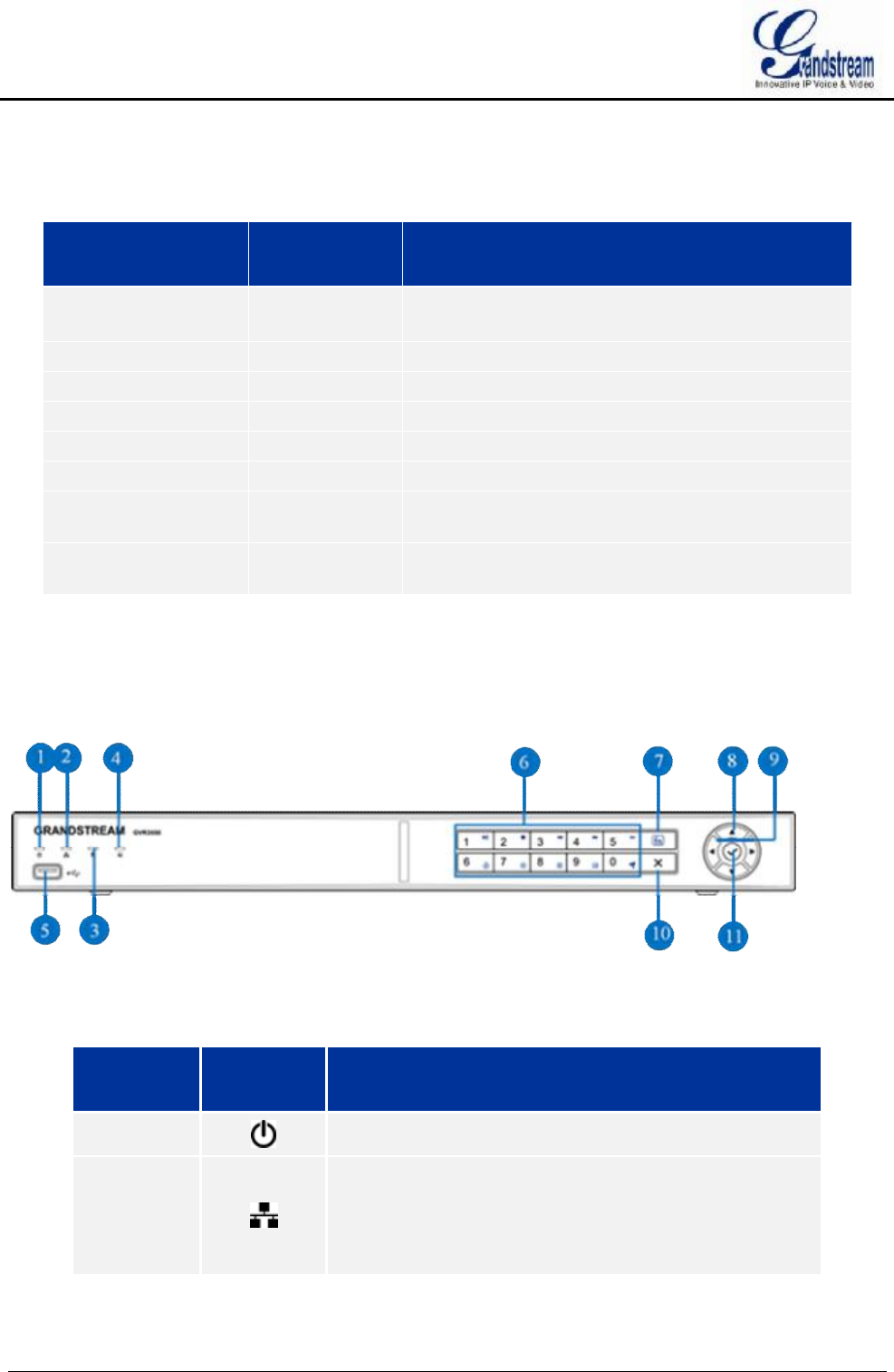
GVR3550 PRODUCT APPEARANCE
Figure 1 GVR3550 Front Panel
Table 4 GVR3550 Front Panel Buttons Explanation
No. Buttons Explanation
① Power indicator.
②
Network Indicator.
Ÿ Dark: Abnormal network connection or has no access
to network
Ÿ Green: Normal network connection
Ÿ Flashing: Transmitting data...
GVR3550/GVR3552 User Manual Page 17 of 125
③
HDD Indicator.
Ÿ Solid green: HDD perfectly working
Ÿ Flashing: Reading data...
Ÿ Nark: No HDD detected
④
Function Status Indicator. To indicate whether the
numeric buttons are being used as functional button once
pressed the function button.
Ÿ Green: Functional status
Ÿ Nark: Numerical status
⑤ USB Interface. To connect to USB devices like mouse,
keyboard and USB flash drive.
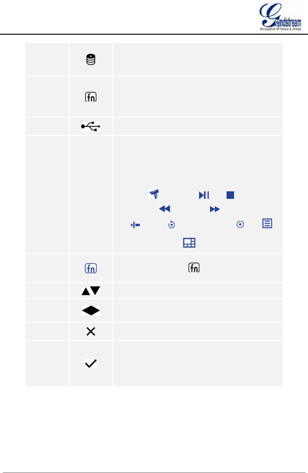
⑥
Numeric Buttons.
To input numbers and switch previews.
Once pressed the function button, the numeric buttons will
be used as functional buttons.
Number 0-9 are corresponding to the following functions:
Enable PTZ , Start/Pause , Stop ,
Fast Backward , Fast Forward , Single Frame
Jump , Playback , Record Mode Setting , Menu ,
Switch preview windows ,
⑦
Function Button. To switch between numeric mode and
function mode. The button indicates the status of the
function button.
⑧ Up and Down Navigation Buttons
To switch among the activated controls
⑨
Left and Right Navigation Buttons
Ÿ To switch among the activated controls
Ÿ Controls the progress bar when playback.
⑩ Cancel Button
Back to the previous menu or cancel operation.
11
Confirm Button
Ÿ Confirm.
Ÿ Switch to the default button.
Ÿ Enter menu.
Ÿ Select a check box or enable toggle ON/OFF button.
Pause/Resume auto patrol when auto patrol preview.
GVR3550/GVR3552 User Manual Page 18 of 125
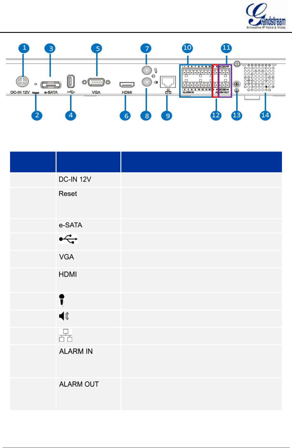
Figure 2 GVR3550 Back Panel
Table 5 GVR3552 Back Panel Buttons Explanation
Icon Buttons Explanation
① Power Input. Input 12V DC
② Reset Button. To reboot device or reset factory.
Ÿ Long press for more than 10 seconds: factory reset
Ÿ Press when power on: reset when the GVR is
abnormal
③ eSATA Interface. To connect eSATA device
④ USB Interface. To connect to USB devices like mouse,
keyboard and USB flash drive
⑤ VGA Video Output. To output analog video signal,
connecting to a monitor to view record
⑥ HDMI. HD audio/video output interface, transmit
uncompressed HD video and multichannel audio data to
display device with HDMI interface
⑦
Audio Input. Receiving analog audio signal from
microphone, pickups and other devices
⑧ Audio Output. Output analog audio signal to device like
speaker
⑨
Network Port. 10M/100M/1000M adaptive Ethernet
interface
⑩ Alarm Input Interfaces 1-16.
16 alarm input interfaces receiving binary signals from
external alarm sources like normally-closed alarm and
normally-open alarm.
11 Alarm Output Interfaces 1-2.
2 set of alarm output interfaces, output alarm signal to
external alarm device, power supply is required for external
alarm device
GVR3550/GVR3552 User Manual Page 19 of 125
12 -- Alarm Grounding.
13
Grounding.
14 FAN. For heat dissipation
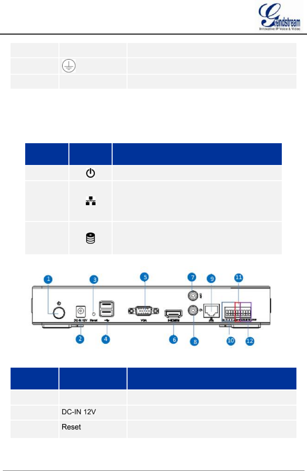
GVR3552 PRODUCT APPEARANCE
Table 6 GVR3552 Power Indicator Explanation
No. Buttons Explanation
① Power indicator.
②
Network Indicator.
Ÿ Dark: Abnormal network connection or has no access
to network
Ÿ Green: Normal network connection
Ÿ Flashing: Transmitting data...
③
HDD Indicator.
Ÿ Solid green: HDD perfectly working
Ÿ Flashing: Reading data...
Ÿ Nark: No HDD detected
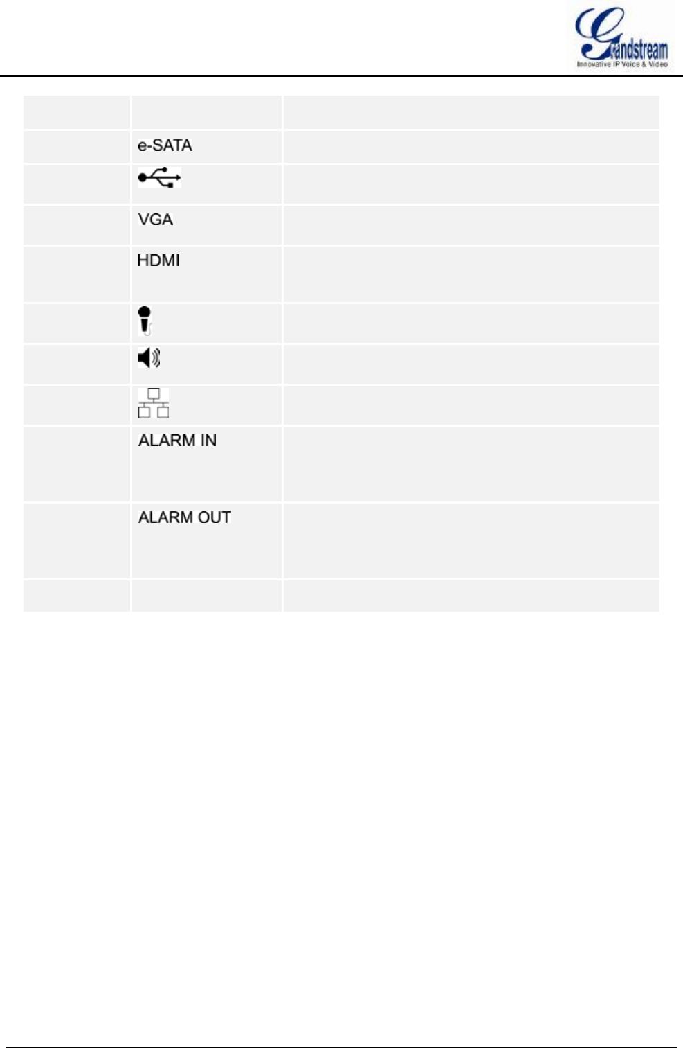
Figure 3 GVR3552 Back Panel
Icon Buttons Explanation
① POWER Power switch
② Power Input. Input 12V DC
③ Reset Button. To reboot device or reset factory.
Ÿ Long press for more than 10 seconds: factory reset
GVR3550/GVR3552 User Manual Page 20 of 125
Ÿ Press when power on: reset when the GVR is
abnormal
③ eSATA Interface. To connect eSATA device
④ USB Interface. To connect to USB devices like mouse,
keyboard and USB flash drive
⑤ VGA Video Output. To output analog video signal,
connecting to a monitor to view record
⑥ HDMI. HD audio/video output interface, transmit
uncompressed HD video and multichannel audio data to
display device with HDMI interface
⑦ Audio Input. Receiving analog audio signal from
microphone, pickups and other devices
⑧ Audio Output. Output analog audio signal to device like
speaker
⑨ Network Port. 10M/100M/1000M adaptive Ethernet
interface
⑩ Alarm Input Interfaces 1-16.
16 alarm input interfaces receiving binary signals from
external alarm sources like normally-closed alarm and
normally-open alarm.
11 Alarm Output Interfaces 1-2.
2 set of alarm output interfaces, output alarm signal to
external alarm device, power supply is required for external
alarm device
12 -- Alarm Grounding.
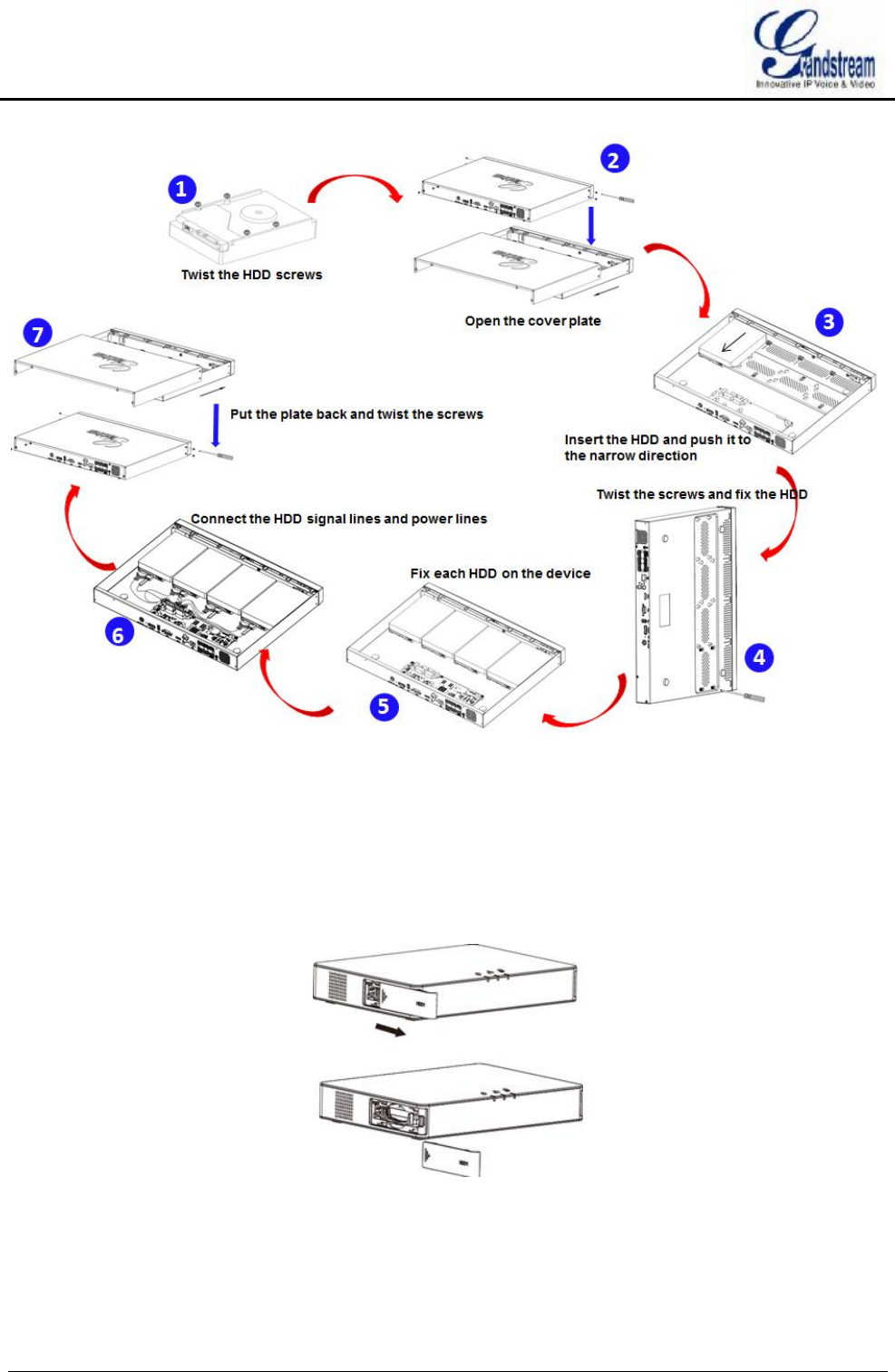
INSTALLING GVR3550 HDD
The GVR3550 contains no HDD with packaging, the first-time users need to check the device and install
HDD. Please install the GVR3550 HDD according to the following procedures:
1. Twist four screws gently on the bottom of HDD, do not twist too tight;
2. Remove the fixed screws on the back and side panel of the main case, open the cover plate to find the
HDD installing position;
3. Side put the main case, aims HDD with four screws on at the corresponding 4 screw holes on the
baseplate and then twist the screws;
4. Repeat the previous steps to install other HDDs;
5. Connect HDD data lines and power cables to the interfaces of the mainboard;
6. Put the cover plate back and twist back the screws.
GVR3550/GVR3552 User Manual Page 21 of 125
Figure 4 GVR3550 HDD Installation Diagram
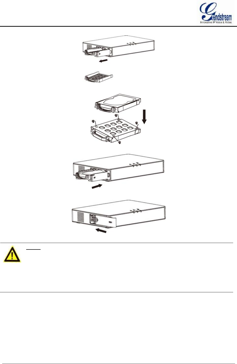
INSTALLING GVR3552 HDD
Please install the GVR3552 HDD according to the following procedures:
1. Open the device by pushing forward the front panel cover of HDD;
2. Take out the HDD case;
GVR3550/GVR3552 User Manual Page 22 of 125
3. Put the 2.5" HDD into the HDD case in upright position then tighten the screws to install the HDD;
4. Push the HDD case into the slot in upright position until "click" sound heard;
5. Close the front cover panel;
6. Repeat the above steps to install 2nd HDD.
NOTE:
Ø It is Recommended to use at least 7200rpm HDD or higher. Dedicated PC HDD
is not recommendable. Unqualified HDD may unable to work properly.
Ø GVR3550/GVR3552 does NOT support HDD hot swap. When
GVR3550/GVR3552 is running, plug the HDD may cause fail to read /write
HDD data or unable to identify the data. Grandstream will take no
responsibility for the damage caused by wrong operations.
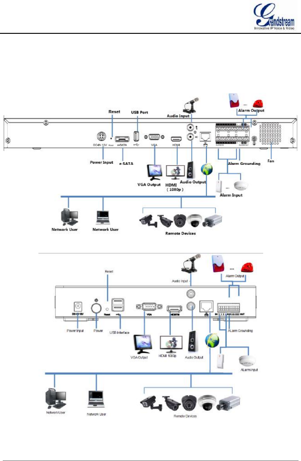
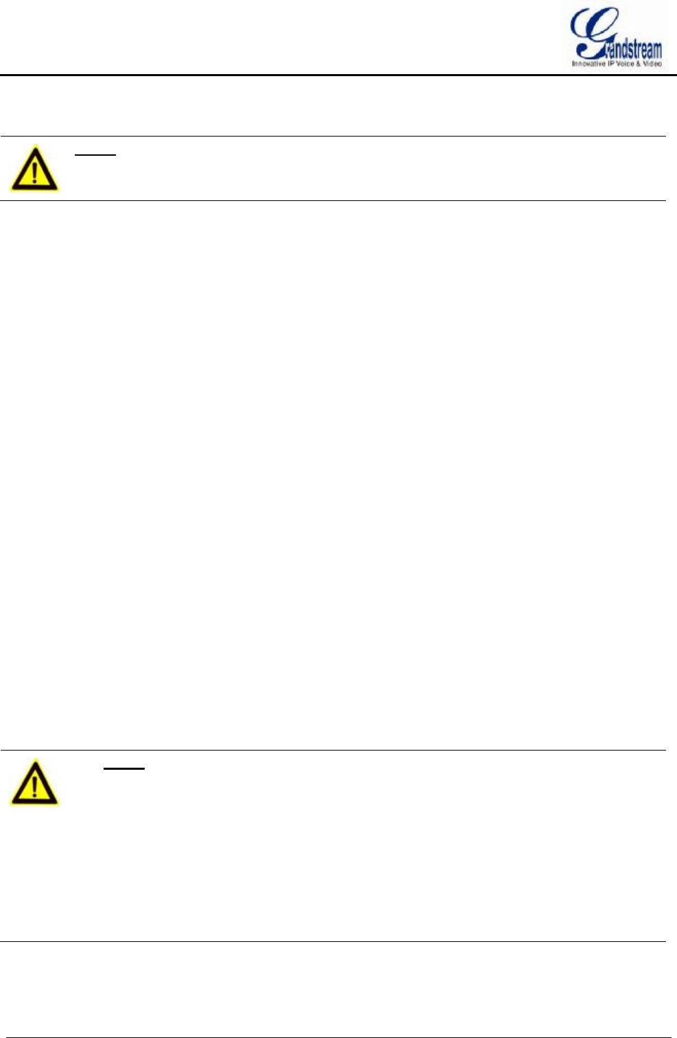
CONNECT GVR3550/GVR3552
Please connect the GVR3550/GVR3552 according to the following procedures:
1. Install the GVR3550/GVR3552 HDDs by following the steps in chapter Installing GVR3550/GVR3552
HDD;
GVR3550/GVR3552 User Manual Page 23 of 125
2. Plug in the network cables and connect the device to the display device;
3. Connect the mouse, keyboard, alarm input and output devices (optional);
4. Power up GVR3550/GVR3552 and the optional devices after connecting power cable;
5. The power indicator will be on if the GVR3550/GVR3552 is on, if all devices have been powered up
successfully, the connection is done.
Figure 5 Connect GVR3550 Diagram
Figure 6 Connect GVR3552 Diagram

GVR3550/GVR3552 User Manual Page 24 of 125
NETWOKR CONNECTION
Users could log in the Web page with the administrator account after plugging in the network cable to
GVR3550/GVR3552, go to Menu ->Status-> Network Status to view the network status like IP address and
network sending/receiving rate. For details, please refer to the chapter Network Info.
EXTERNAL USB DEVICE
GVR3550/GVR3552 USB interface could be connected to mouse and keyboard, or a USB storage device.
NOTE: Ø The USB interface voltage on the front panel of the GVR3550 is a little higher
than the one on the back panel, it is suggested that the USB interface on the
back panel connect to mouse and keyboard while the one on the front panel
connect to USB storage devices.
PLUG IN USB MOUSE/KEYBOARD
Users could check whether the mouse and keyboard are installed successful after plugging in them. The
mouse or keyboard might be not compatible with GVR3550/GVR3552. If can't be detected, please replace
the mouse or keyboard and try again.
When the USB mouse is plugged into GVR3550/GVR3552, users could make the following operations with
the mouse.
Single click the left mouse:
· Access a functional menu.
· Select one option in a drop-down box.
· Confirm one operation like soft keyboard input after put the cursor in the input box.
· Bring out quick action bar when select preview screen.
Double click the left mouse:
· Switch between one window display in fullscreen and Multi-windows when preview.
· Save the alarm area and go back to the main menu.
Single click the right mouse:
· Bring up the shortcut menu in real-time monitoring mode.
· Go back to the preview screen on main menu or the playback screen.
· Save the alarm area and go back to the main menu.
Press the left mouse and drag:
· Drag one preview screen to another screen and switch their positions.
· Drag digital amplified area or alarm area.
· Drag the playback progress bar to set time point.
GVR3550/GVR3552 User Manual Page 25 of 125
· Drag the action box ( PTZ, Image config, Encoding Config) on preview screen.
NOTE: Ø If in a rare case that the mouse is not detected, the mouse might not compatible
with the GVR3550, please replace the mouse.
PLUG IN USB STORAGE DEVICE
Users could click right mouse to check if there is "Uninstall" option in the menu after plugging in the USB
device correctly. The option means the USB device is normal for use. Users could also go to
Settings->System Settings->Basic System Settings, click "Refresh" button to check the USB device status.
INSTALLING eSATA
Plug in the eSATA cable to the corresponding interface on the back panel of GVR3550, power up eSATA or
electrify it with USB cable (according to eSATA specific situation). Users could go to Settings->System
Settings->HDD Management to view details like HDD Space, Free Space, HDD Status, HDD Type after
installing eSATA. For details, please refer to the chapter HDD Management.
CONNECT HDMI MONITOR
Connect one end of the HDMI cable to the interface on the back panel of the GVR3550/GVR3552, and the
other end to the corresponding interface of the HDMI monitor. Once powered up, users could see the
preview screen of GVR3550/GVR3552 on HDMI monitor. GVR3550/GVR3552 can automatically adapt to
HDMI monitor with 1080p and 720p resolution.
CONNECT VGA MONITOR
Connect one end of the VGA cable to the interface on the back panel of the GVR3550/GVR3552, and the
other end to the corresponding interface of the VGA monitor. Once powered up, users could see the boot
screen of GVR3550/GVR3552 on VGA monitor.
Ø NOTE:
Ø VGA does not support automatic resolution matching, users have to manual
set it.
Ø There is only one valid output when connect to VGA and HDMI monitor the
same time. HDMI is valid while VGA is not by default.
Ø HDMI supports automatic resolution matching with 1080p and 720p
resolution only when set display to "auto".
Ø When set display to "auto", if reboot GVR3550/GVR3552 without
connecting to any displays, VGA output will be displayed by default.
Connect to one HDMI display then reboot GVR if you want it to display
HDMI output.
Ø Go to System Settings->Display to set parameters.
GVR3550/GVR3552 User Manual Page 26 of 125
CONNECT ALARM DEVICE
Alarm input/output connection procedures are as follows:
1. Connect the alarm input device to the alarm input port;
2. Connect the alarm output device to the alarm output port;
3. Enter GVR3550 menu, configure alarm input/output parameters on Alarm Settings page. Alarm serial
No.1 corresponds to the first alarm input on GVR3550 I/O interface, the following numbers keep to the
same matching sequence. Set normally-opened alarm and normally-closed alarm according to the
corresponding VIH /OV when alarm;
4. Set alarm output on Alarm Settings page. Alarm output 1 corresponds to the first alarm output; the
following numbers keep to the same matching sequence.
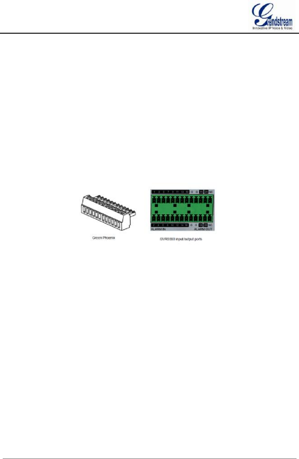
GVR alarm input/output ports on back panel could be connected to alarm input/output devices via the
proprietary green phoenix.
Figure 7 Connect Input/Output Device With Phoenix
16 alarm input ports: One alarm input is consisting of one alarm input pin and one (public) G port.
2 set of alarm output ports: One alarm output is consisting of 1A and 1B, while 2A and 2B make the second
alarm output.
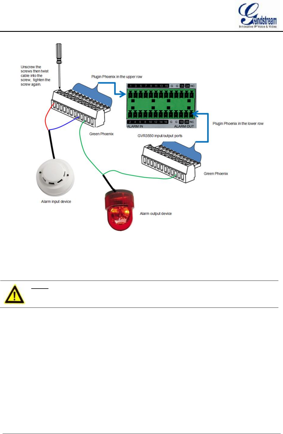
Connect cables according to the port instruction on the back panel of GVR3550.
· Connect the first cable from alarm input device to ALARM IN 1, and the second cable to G port.
· Connect the first cable from alarm output device to ALARM OUT 1A, and the second cable to ALARM
OUT 1B.
Connect other ports in the same way, see the connection diagram below.
GVR3550/GVR3552 User Manual Page 27 of 125
Figure 8 Alarm Device Connection Diagram
You need an external power source when connecting to an output device.
· Prepare a DC12V external voltage when need external DC power supply.
· Prepare an external relays when need external AC power supply, or it may destroy the device and there
might be a potential security liability.
NOTE: Ø When power the alarm input device with an external power supply, the device
should be common-grounded with GVR3550.
EXTERNAL INTERCOM DEVICE
GVR3550/GVR3552 supports web paging and local paging.
1. Connect the audio-input device like microphone or pickups with RCA interface to the audio input
interface on the back panel of GVR;
2. Connect the audio-output device like speaker or stereo with RCA interface to the audio output interface
on the back panel of GVR.
(The steps above ensure the GVR3550/GVR3552 could input or output audio);
3. Connect the microphone to PC audio input interface, while the earphone or stereo is being connected to

GVR3550/GVR3552 User Manual Page 28 of 125
PC audio output interface to make PC input/output audio.
Connect the audio input/output devices to the compatible cameras to input/output audio.
NOTE:
Ø Only supports RCA audio input/output devices.
GVR3550/GVR3552 User Manual Page 29 of 125
PRODUCT OVERVIEW
GVR3550/GVR3552 SPECIFICATIONS
Table 7 GVR3550/GVR3552 Software Specifications
Specification GVR3550 GVR3552
Video
Recording
Supports synchronous 24 cameras
720p (with 1280x720 resolution) record
or 12 cameras 1080p (with 1920x1080
resolution) record
Supports synchronous 16 cameras 720p (with
1280x720 resolution) record or 8 cameras
1080p (with 1920x1080 resolution) record
Recording
Rate Supports up to 48 Mbps recording rate Supports up to 32 Mbps recording rate
Recording
Mode
Supports schedule record ,alarm record
and manual record
Supports schedule record ,alarm record and
manual record
Audio
Compression G.711 a/u law G.711 a/u law
Audio
Recording
Synchronized Audio and Video
recording Synchronized Audio and Video recording
Video
Compression H.264 BP/MP/HP H.264 BP/MP/HP
Local Live
Preview
4 cameras 720p or 2 cameras 1080p
output simultaneously, 16 cameras VGA
output, up to synchronous 24 cameras
remote live preview
4 cameras 720p or 2 cameras 1080p output
simultaneously, VGA output, up to
synchronous 24 cameras remote live preview
Playback 4 cameras simultaneous local and
remote playback
4 cameras simultaneous local and remote
playback
Trigger Event
Alarm
Motion detection alarm, I/O alarm, event
alarm and abnormal alarm
Motion detection alarm, I/O alarm, event alarm
and abnormal alarm
Intelligent
Search
Time & date, recording type, cameras,
tag Time & date, recording type, cameras, tag
Total Storage Grandstream customized Grandstream customized
RAID
RAID 0 and RAID 1. It is recommend not
to use more than 16 cameras when
using RAID1
RAID 0 and RAID 1. It is recommend not to
use more than 16 cameras when using RAID1
Redundancy Supports record backup to USB external
devices
Supports record backup to USB external
devices
GVR3550/GVR3552 User Manual Page 30 of 125
QoS Layer 2 QoS (802.1Q, 802.1p) and
Layer 3 QoS (ToS, DiffServ, MPLS)
Layer 2 QoS (802.1Q, 802.1p) and Layer 3
QoS (ToS, DiffServ, MPLS)
IP Camera
All Grandstream GXV36xx series IPCs,
GXV35xx DVS or compatible ONVIF
IPCs
All Grandstream GXV36xx series IPCs,
GXV35xx DVS or compatible ONVIF IPCs
Provisioning Supports HTTP, HTTPS, ONVIF Supports HTTP, HTTPS, ONVIF
Network
Protocols
TCP/UDP, RTP/RTCP/RTSP,
HTTP/HTTPS, ARP, ICMP, DNS,
DDNS, DHCP (client and server), NTP
(client and server), SSH, PPPoE, LLDP,
ONVIF 2.2
TCP/UDP, RTP/RTCP/RTSP, HTTP/HTTPS,
ARP, ICMP, DNS, DDNS, DHCP (client and
server), NTP (client and server), SSH,
PPPoE, LLDP, ONVIF 2.2
Security HTTPS, 802.1x (pending), SSH
Table 8 GVR3550/GVR3552 Hardware Specifications
Name GVR3550 GVR3552
Interface
1 HDMI interface
1 VGA interface
1 x 10M/100M/1000Mbps auto-sensing
RJ45 port
1 RCA Audio Input interface
1 RCA Audio output interface
1 HDMI interface
1 VGA interface
1 x 10M/100M/1000Mbps auto-sensing RJ45
port
1 RCA Audio Input interface
1 RCA Audio output interface
Alarm In Terminal 16 inputs (NO/NC), Vin
2.5V~12V,Iin 2.5mA~30mA
Terminal 4 inputs (NO/NC), Vin 2.5V~12V,Iin
2.5mA~30mA
Alarm Out Terminal 2 outputs (Relay), 0.5A at 125
VAC; 2A at 30 VDC
Terminal 2 outputs (Relay), 0.5A at 125 VAC;
2A at 30 VDC
UPS UPS management via USB or
USB-Serial UPS management via USB or USB-Serial
USB Interface 2 2.0 USB interfaces 2 2.0 USB interfaces
eSATA 1 eSATA interface No eSATA interface
LED Indicator Power, LAN Link/Activity, Hard Drive
Activity, Keyboard Power, LAN Link/Activity, Hard Drive Activity
Remote
Control Supports IR remote control Not support IR remote control
RTC Supports RTC Supports RTC
Internal HDD
Up to 4 SATA hard drives with
maximum 16TB storage, the maximum
capacity of each hard drive is 4Tb (Hard
drive is not included in GVR3550
packaging)
Up to 2 SATA hard drives with maximum 4TB
storage, the maximum capacity of each hard
drive is 2Tb (Hard drive is not included in
GVR3552 packaging)
Universal
Power Supply
Input: 100~240V 50/60Hz; Output:
12V/5A 60W
Input: 100~240V 50/60Hz; Output: 12V/5A
60W
GVR3550/GVR3552 User Manual Page 31 of 125
Environmental
Operation: 0°C to 50°C
Storage: -20°C to 60°C (not include
HDD temperature)
Humidity: 10% to 90% non-condensing
Operation: 0°C to 50°C
Storage: -20°C to 60°C (not include HDD
temperature)
Humidity: 10% to 90% non-condensing
Mounting 1U rack mount with front brackets Supports desktop installation
Compliance
FCC: Part 15 (CFR 47) Class B
CE: EN 55022,EN 55024, EN
61000-3-2 ,EN 61000-3-3, EN 60950
RCM: AS/NZS CISPR22, AS/NZS
CISPR24,AS/NZS 60950
Comply with R & TTE, RoHS & WEEE
FCC: Part 15 (CFR 47) Class B
CE: EN 55022,EN 55024, EN 61000-3-2 ,EN
61000-3-3, EN 60950
RCM: AS/NZS CISPR22, AS/NZS
CISPR24,AS/NZS 60950
Comply with R & TTE, RoHS & WEEE
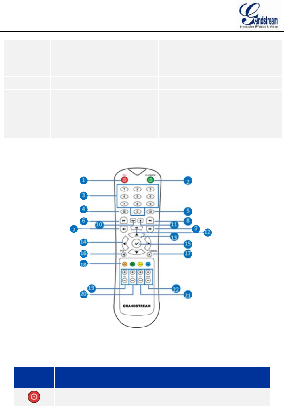
IR REMOTE CONTROL
Figure 9 IR Remote Control
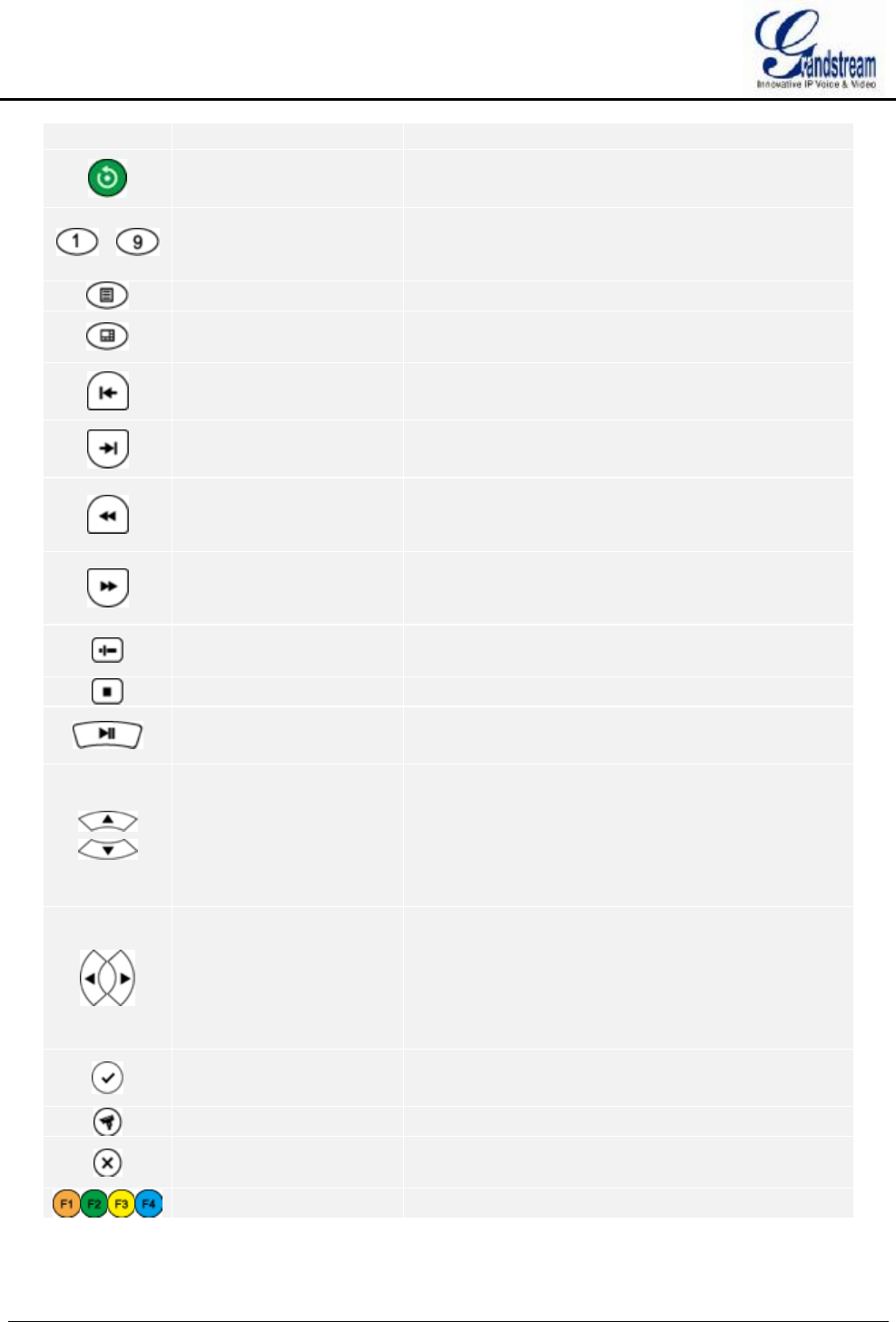
Table 9 GVR3550 Remote Control Icons Explanation
Icon Name Explanation
REC Button Manual start/stop recording. Use REC button and the
navigation buttons to select the camera to record in t
GVR3550/GVR3552 User Manual Page 32 of 125
he recording menu.
Playback Button Enter playback screen.
…
Numeric Buttons
Features the same function as the numeric buttons on
the front panel (only numeric function) to switch
preview screen.
MENU Button Enter menu.
Multi-windows Button Switch the screen to a single window or
multi-windows.
Single-frame back
Button Single frame playback of the video.
Single-frame Step
Button Single frame forward of the video.
Fast Backward Button
Various fast backward speeds and normal playback
mode, the speed would be displayed on the playback
screen.
Fast Forward Button
Various fast forward speeds and normal playback
mode, the speed would be displayed on the playback
screen.
Skip Button Switch to skip mode. User it with the Up and Down
buttons to choose when to play videos.
Stop Button Stop playing recorded video.
Play/Pause Button
Ÿ Press the button to resume video playback.
Ÿ Press the button to pause video playback.
Up and Down
Navigation Buttons
Ÿ Switch the activated controls to move up or
down.
Ÿ Switch cameras to up or down when preview.
Ÿ Auxiliary function (e.g.: Control and operate the
PTZ menu).
Left and Right
Navigation Buttons
Ÿ Switch the activated controls to move left or right.
Ÿ Switch cameras to left or right when preview.
Ÿ Control the progress bar when playback video.
Ÿ Auxiliary function (e.g.: Control and operate the
PTZ menu).
OK Button
Ÿ Confirm operations.
Ÿ Switch to the default button.
PTZ Control Button Enable/Disable PTZ Control.
Cancel Button Back to the previous page, or cancel operations like
close the top-level page or controls).
Function Buttons 1-4 F1, F2, F3 and F4 Function buttons.
GVR3550/GVR3552 User Manual Page 33 of 125
Vol Button +- Adjust the cameras volume when preview.
A-I Button +- Adjust aperture at PTZ control.
A-F Button +- Adjust focus at PTZ control.
Zoom Button +-
Ÿ Electronic zoom adjustment at PTZ control.
Ÿ Electronic zoom adjustment when one camera
playback video at full screen.
The correct way to use IR remote control: Batteries must be installed before use. Please aim the remote
control at the IR receiver on the GVR3550 then make operations. If the GVR3550 receives the control’s
command, you can use the control to manipulate the GVR3550. If failed, please check whether the following
reasons are the causes:
Ÿ Check the battery polarities.
Ÿ Check whether the battery power.
Ÿ Check whether the remote sensor is obscured.
Ÿ Check whether a fluorescent lamp is being used nearby.
If the remote still can’t function normally beyond the above situations, please change a remote and try again,
or contact the device provider.
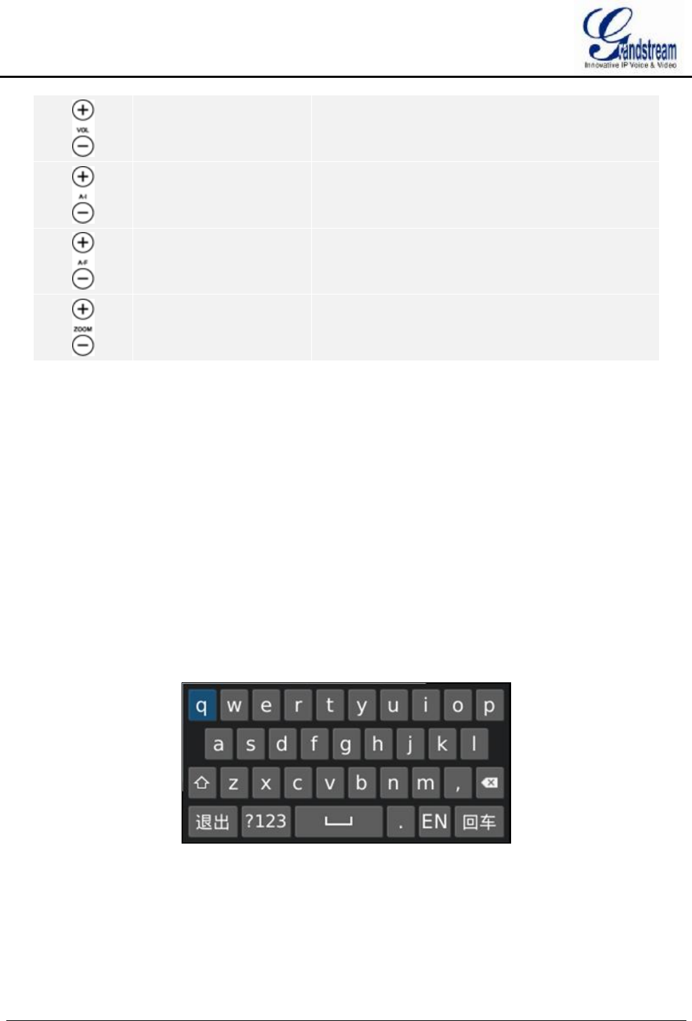
INPUT METHOD
GVR3550/GVR3552 supports English and Chinese input methods; the input interface is as shown below.
Figure 10 Soft Keyboard—English Input Method
GVR3550/GVR3552 User Manual Page 34 of 125
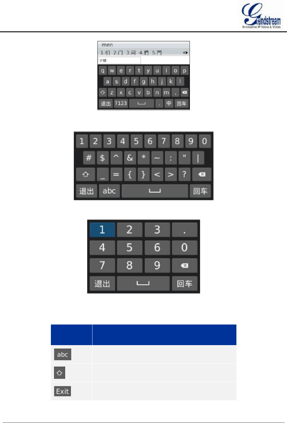
Figure 11 Soft Keyboard—Chinese Input Method
Figure 12 Soft Keyboard—Symbols and Numbers
Figure 13 Soft Keyboard—Numeric Keyboard
Table 10 Soft Keyboard Specifications
Icon Specifications
Input lowercase
Ÿ Switch CapsLock
Ÿ Switch between symbols and numbers
Exit keypad
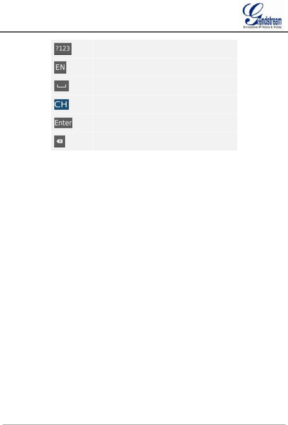
GVR3550/GVR3552 User Manual Page 35 of 125
Switch to Symbols & Numbers
English input method. Tap again to switch to Chinese
input method.
Space
Chinese input method. Tap again to switch to English
input method.
Enter
Backspace

GVR3550/GVR3552 User Manual Page 36 of 125
LOCAL OPERATIONS
In this chapter, we take using the mouse as an example.
USING THE WIZARD
Users could start the GVR via the wizard for basic configuration to make it work properly.
1. Enter administrator password (the default is "Admin") to log in the GVR. Check to confirm whether to
enable the wizard next time when boot up the device;
2. Click on "Next" to access Basic Settings page to configure language and time. Set time zone and system
time;
3. Click on "Next" to access Network Settings page to set IP address, subnet mask and gateway
parameters;
4. Click on "Next" to access HDD Management page to set HDD array and HDD full strategy;
5. Click on "Next" to access Camera Management page to add camera;
6. Click on "OK" to finish setup.
LOGIN
The factory default username is "admin", the password is "admin". Users have to login again if timeout
without operations. Password change is recommended after the initial login.
After logging in the GVR local page, users could click on the menu button in the lower left corner of
the page to login, or click right mouse and then select any item in a pop-up menu to bring up the GVR login
page.
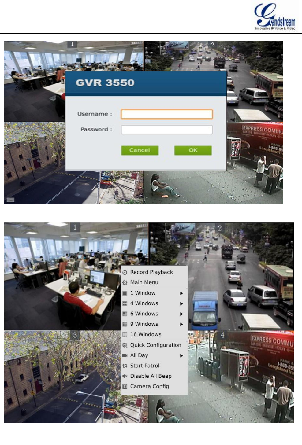
GVR3550/GVR3552 User Manual Page 37 of 125
Figure 14 Local Login Page
GVR3550/GVR3552 User Manual Page 38 of 125
Figure 15 Live Preiew Page–Right Click Menu
LOCAL PREVIEW
GVR3550/GVR3552 would directly enter live preview screen once booted up, users could preview the live
preview screen without login but unable to make any operations. Only after logged in users could make basic
preview operations and other setups.
PREVIEW STATUS
Preview camera status: The camera has not been added, camera preview, connecting the camera, camera
connection failed.
Table 11 Preview Page–Camera Status Explanation
Icon Name Explanation
Add camera If there is no existing camera, click this button to quick enter the
camera settings page to add camera.
-- Camera preview Display camera preview page.
Camera
connection
Failed
Failed to connect camera.
Stop preview
when recording
Failed
The insufficient performance of GVR may cause preview failure. Tap
on the icon to preview the closed page.
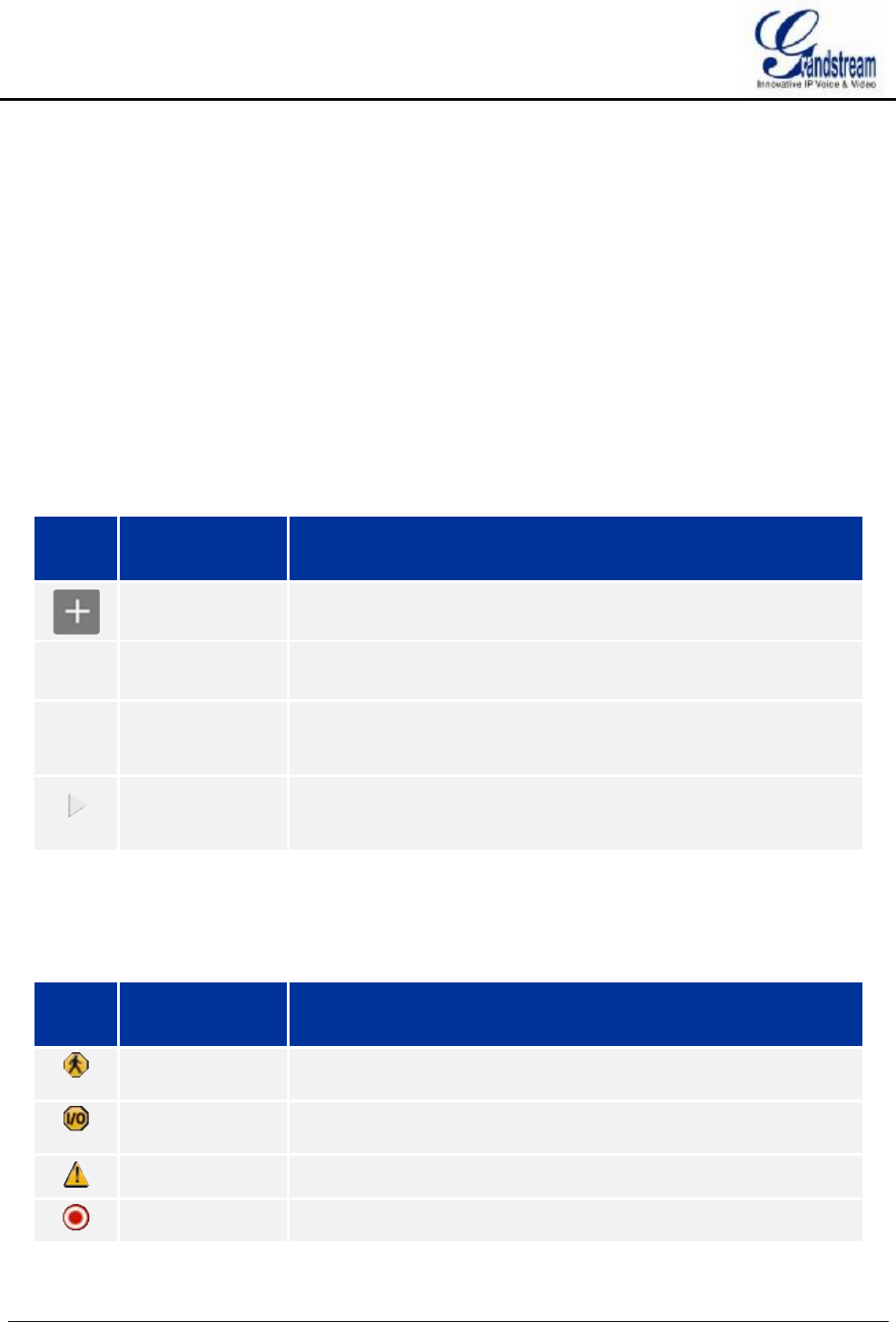
On the preview page, the recording and alarm status of each camera could be distinguished by the tag on the top
right corner of each camera.
Table 12 Preview Status Explanation
Icon Name Explanation
Motion Detection
Alarm
Alarm when detecting dynamic motion in detection area.
I/O Alarm
(camera)
Alarm when the remote camera is connected to IO alarm device.
Signal Loss Alarm when no signal detected.
Recording The monitoring camera is in recording mode.
A dialog box will pop up in the center page to prompt the users if there is an abnormal alarm or local I/O
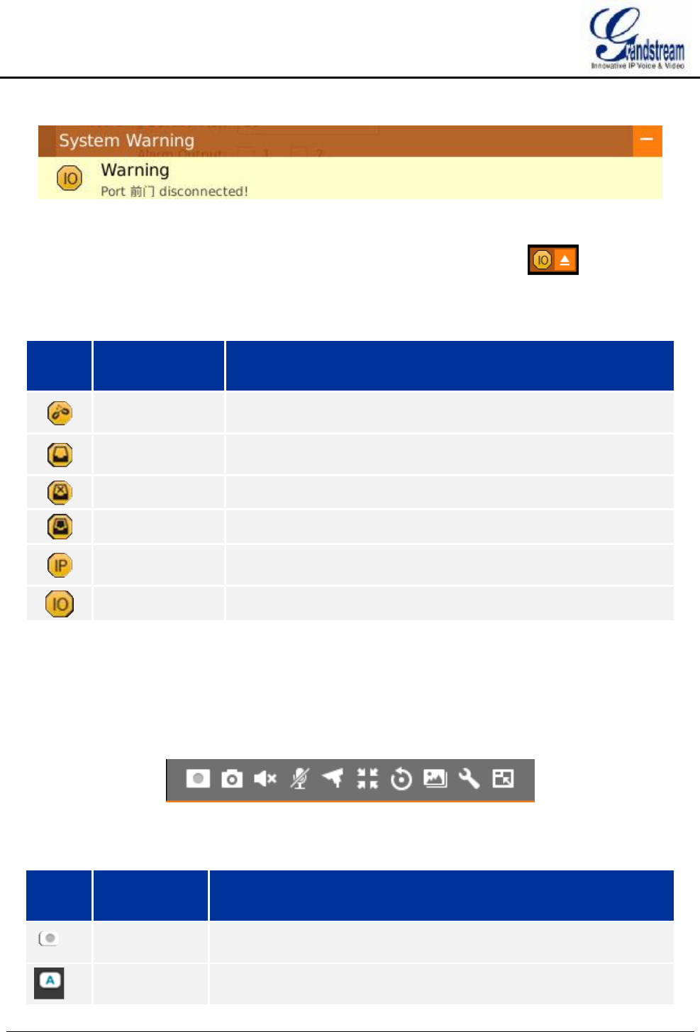
GVR3550/GVR3552 User Manual Page 39 of 125
alarm (go to Settings page to set first), as shown in figure 16.
Figure 16 Abnormal Alarm Prompt
Alarm prompt can be minimized to the lower right corner of the page; you can click to view the alarm
details. If there always been alarm triggers, the prompt will pop up in the center of the page every 5 minutes.
Table 13 Abnormal Alarm Explanation
Icon Name Explanation
Disconnection
Alarm Alarm when the network is disconnected.
HDD Empty
Alarm Alarm when no HDD detected.
HDD Error Alarm
Alarm when HDD is abnormal.
HDD Full Alarm Alarm when HDD is full.
IP Conflict Alarm
Alarm when detecting the IP address of another device is in conflict
with the GVR in the network.
Local I/O Alarm
Alarm when detecting I/O alarm on GVR3550.
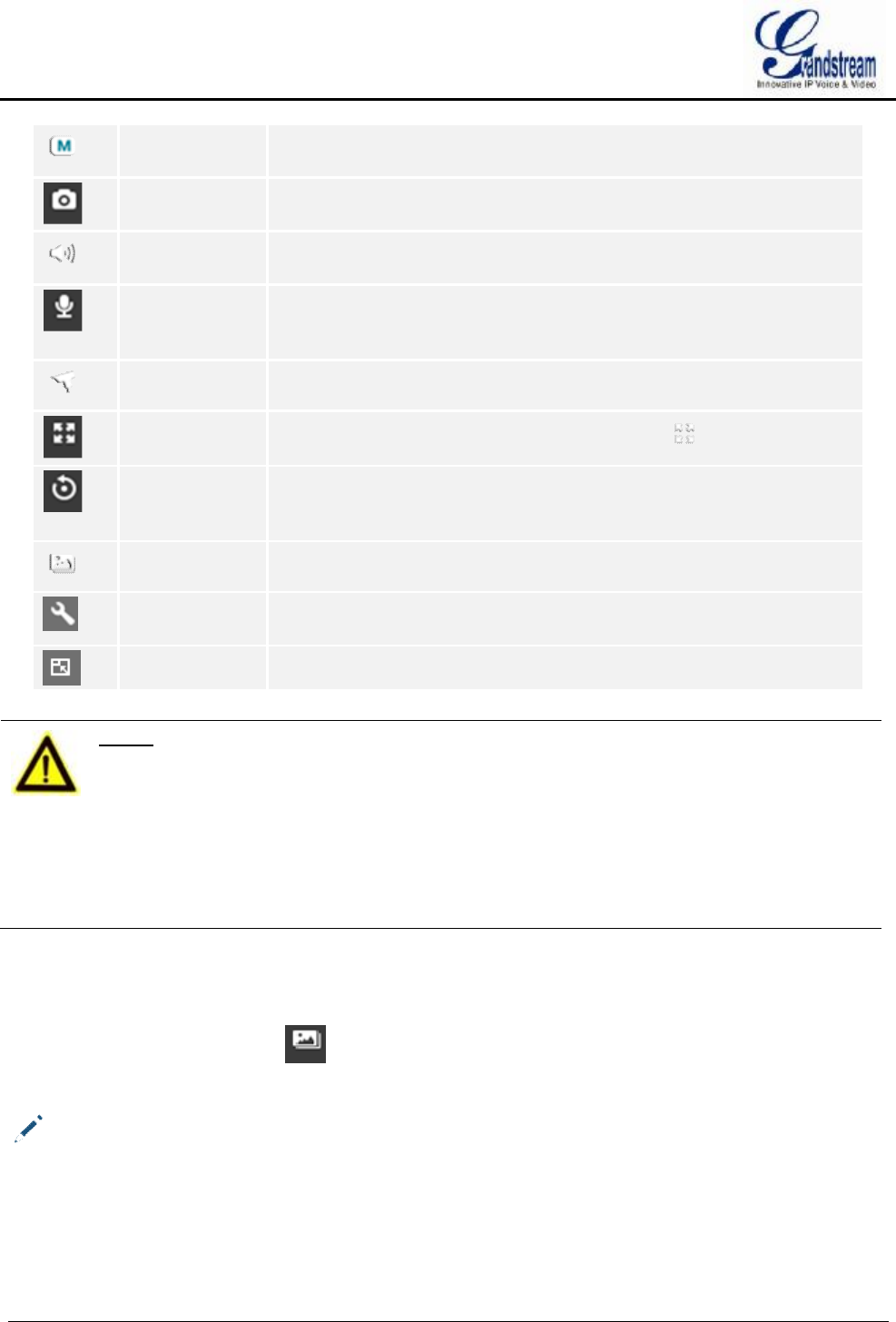
BASIC PREVIEW OPERATION
If need to make basic operations to one specified camera, users could access the preview page and click left
mouse to bring up the menu bar as shown in Figure 17. Click the buttons on the menu bar to make
corresponding operations.
Figure 17 Basic Preview Operations
Table 14 Basic Preview Operations Explanation
Icon Name Explanation
Close
Recording
The camera is not recording now.
Auto
Recording
The camera is in schedule record mode.
GVR3550/GVR3552 User Manual Page 40 of 125
Manual
Recording
The camera is in manual record mode.
Capture Capture preview screenshots. The external storage devices like USB
need to be connected first and users should configure the save path.
Mute/Unmute When the volume in on, if the remote camera is installed with audio input
device, users could listen in to the remote party.
Start /Stop
Intercom
When the intercom in on, if the remote camera is installed with audio
output device, users could speak to the remote camera via local audio
input device.
PTZ Control Click to enable PTZ control to configure PTZ preset, patrol and pattern.
Switch to Full
Screen Switch the current screen to full screen, or click to exit full screen.
Instant
Playback
Playback the video in preset time. It will prompt "The selected camera
has no video "if has no existing recording. Users could set the preset
time in Basic System Settings chapter.
Image Config Enter the corresponding page to adjust the current window image.
Encoding
Config
Enter the corresponding page to configure camera encoding
parameters.
Digital Zoom Only available when in fullscreen mode.
NOTE:
Ø Start intercom will open sound of the camera the same time. Close the intercom
to go back to its previous status.
Ø If one camera has opened sound or enabled intercom, if you want to open sound
or start intercom of the second camera, turn off the previous camera first. If you
close sound or disable intercom of the second camera, the first camera will not
go back to the previous status.
Ø If one camera has opened sound or enabled intercom, you can open sound of the
second camera and the sound of the first camera will be closed while its
intercom is still on.
IMAGE CONFIG
Click on the image config button to bring up the dialogue box as shown in figure 18. Users could
adjust brightness, contrast, saturation and hue by clicking the corresponding Plus/Minus icon or click on
button to access the editing mode. Press the Reset button to restore defaults.
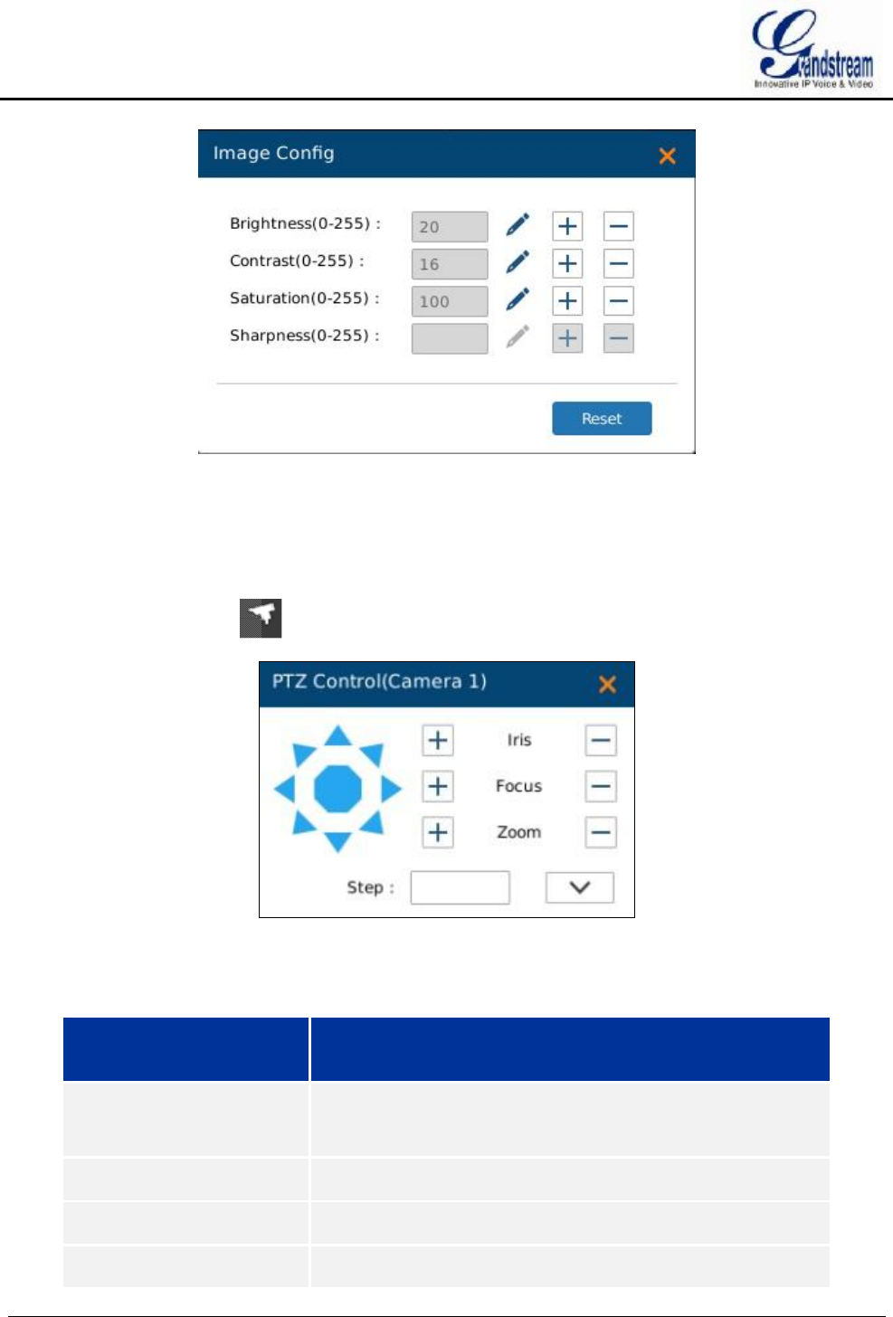
GVR3550/GVR3552 User Manual Page 41 of 125
Figure 18 Image Config Page
PTZ CONTROL
Click the PTZ control button to bring up the PTZ control page, as shown in Figure 19.
Figure 19 PTZ Control Page
Table 15 PTZ Control Parameters Explanation
Name Explanation
PTZ Navigation Buttons
and Reset Button
8 PTZ navigation buttons to control the corresponding eight
PTZ directions. Press the reset button to restore to the original
position.
Iris+ Increasing Iris .
Focus+ Increasing Focus.
Zoom+ Increasing zoom. Only available in fullscreen mode.

GVR3550/GVR3552 User Manual Page 42 of 125
Iris- Reducing Iris.
Focus- Reducing Focus.
Zoom- Reducing zoom. Only available in full screen mode.
Step Control PTZ rotational speed, e.g.: Step 8 is much faster than
step 1. (The step value can be adjusted by clicking left mouse
on digital soft panel or pressing the buttons on the front panel..
Step 8 is the maximum speed.)
More Opening more PTZ control parameters.
PZT Control Ÿ Set PTZ to preset will bring up preset setting page and the
operation panel.
Ÿ Set PTZ to patrol will bring up patrol setting page and the
operation panel.
Ÿ Set PTZ to pattern will bring up contrail setting page and
the operation panel.
Exit Click to exit the PTZ control page.
NOTE:
Ø GVR3550/GVR3552 only supports PTZ control with ONVIF Protocol, the IP
camera should be connected and the PTZ device should be configured properly.
Please make sure the RS-485 cable between PTZ decoder and IP camera is
connected correctly.
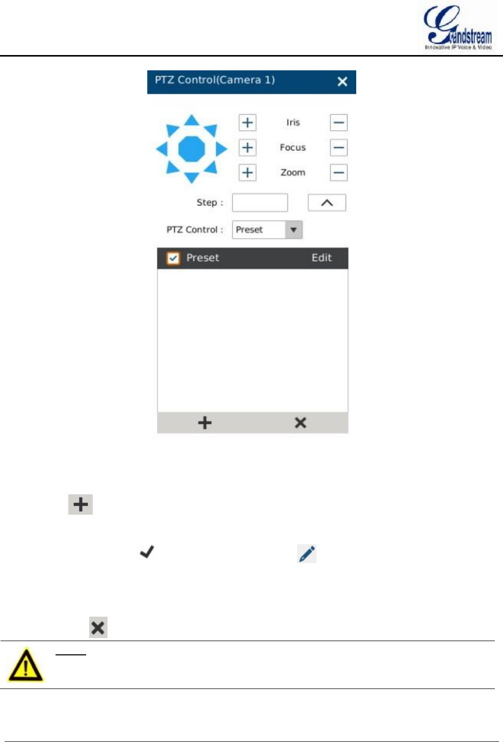
PRESET
When set PTZ to preset, users could add/delete/edit preset on the control panel below. The procedures are
shown in figure 20.
GVR3550/GVR3552 User Manual Page 43 of 125
Figure 20 PTZ Control Page—Preset
1. Adjust the remote camera position via the PTZ navigation panel;
2. Click on to add a new preset;
3. Enter the preset name in the input box or just use the default name;
4. Click the check button to save the preset, or click on the right side of the preset to edit
name;
5. Double click one preset with mouse (or press the OK button on the front panel, or press the OK button
on the remote control) to activate it;
Users could click below the control panel to delete the preset.
NOTE:
Ø Grandstream protocol does not support preset setting..
GVR3550/GVR3552 User Manual Page 44 of 125
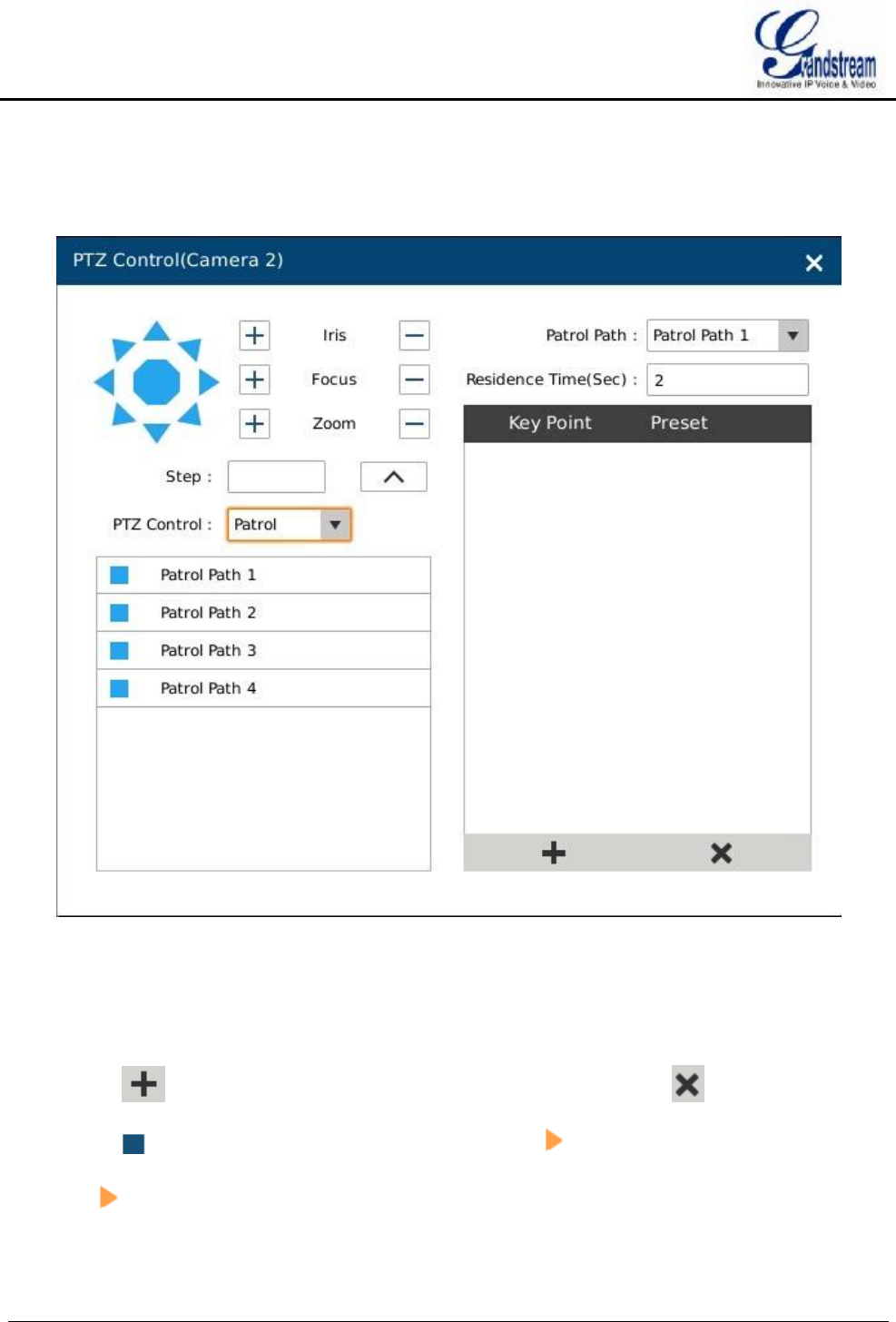
PATROL
When set PTZ to patrol, users could edit and use patrol path on the control panel. The factory default setting
is 4 empty patrol paths. See figure 21.
Figure 21 PTZ Control Page—Patrol
1. Set PTZ to patrol;
2. Select the patrol path;
3. Set the residence time the patrol path stays at each preset;
4. Click on to add key point and set it as one preset. Users could click on to delete the preset;
5. Click on before the patrol path, when it turns to a triangle , PTZ will rotate according to the path.
Click again to stop patrol.
GVR3550/GVR3552 User Manual Page 45 of 125
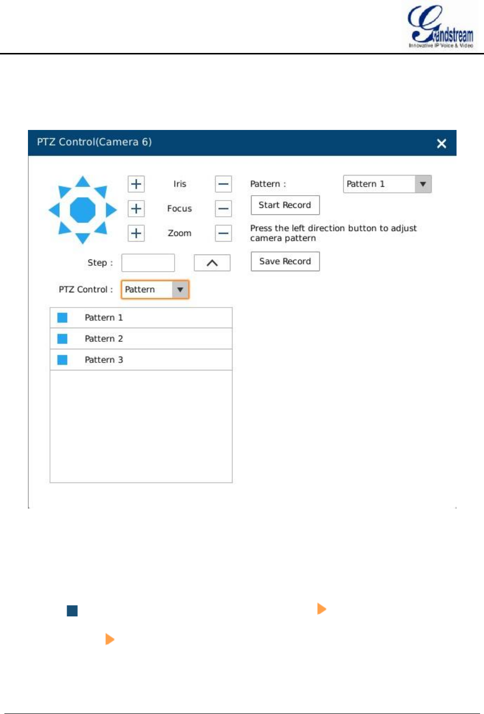
PATTERN
When set PTZ to pattern, users could edit and use pattern on the control panel. The factory default setting is 3
empty patterns. See figure 22.
Figure 22 PTZ Control Page—Pattern
1. Set PTZ control to pattern;
2. Select the pattern name;
3. Click the "Start Record" button to adjust the pattern of remote camera via PTZ navigation panel;
4. Click the "Save Record" button save the pattern;
5. Click on before the pattern, when the button turns to a triangle , the PTZ will rotate according to
the pattern. Click again to stop.
GVR3550/GVR3552 User Manual Page 46 of 125
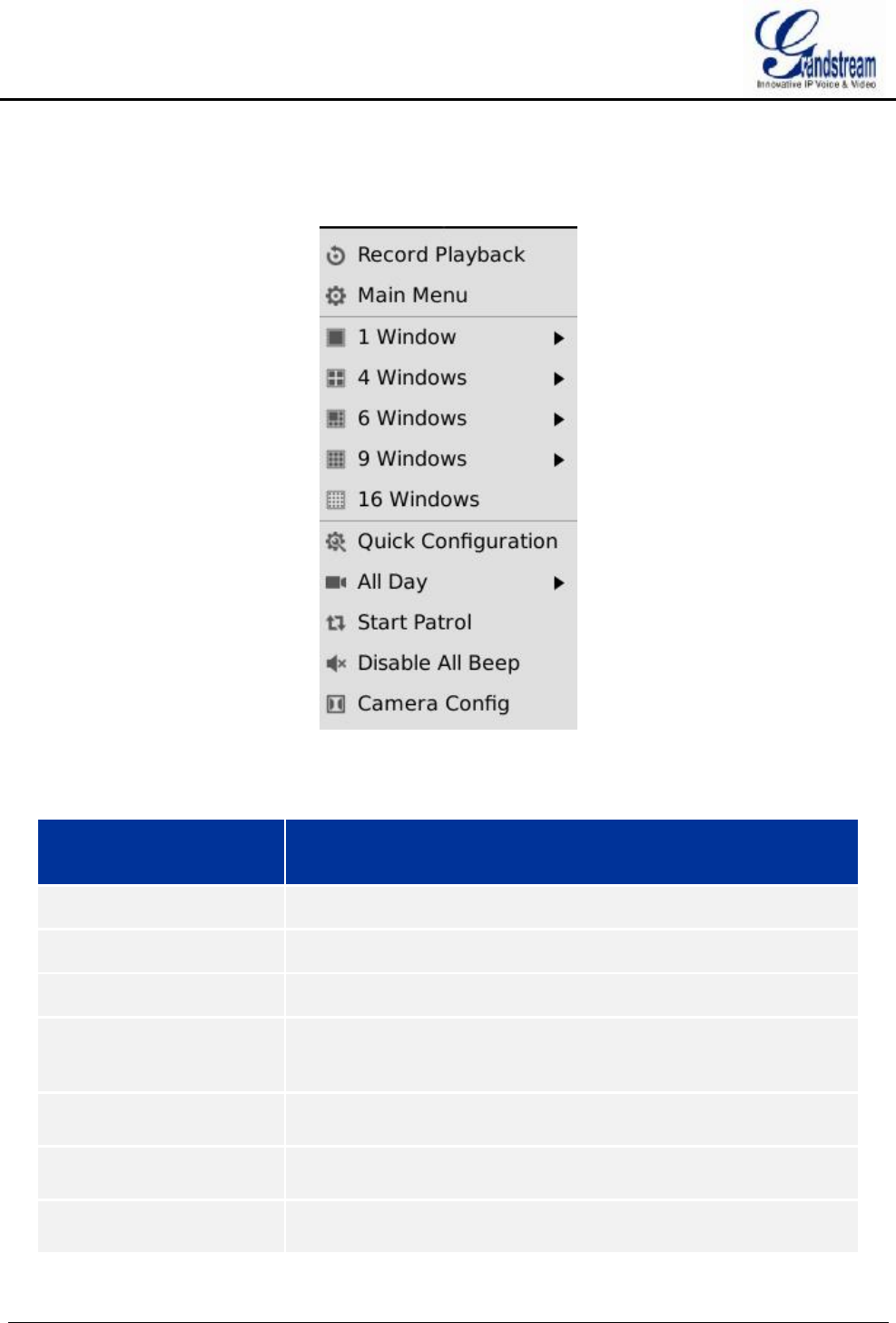
RIGHT-CLICK
Click the right mouse to bring up the right-mouse menu.
Figure 23 Right Click Mouse Menu
Table 16 Right Click Mouse Menu Parameters Explanation
Name Explanation
Record Playback Enter video playback page.
Main Menu Enter system settings page.
1 window Switch to one camera to preview.
4 windows Switch to 4 windows: IMG One-to-Four, IMG Five-to-Eight, IMG
Nine-to-Twelve, IMG Thirteen-to-Sixteen, IMG Seventeen-to-Twenty,
IMG Twenty-one-to-Twenty-four
6 windows Switch to 6 windows: IMG One-to-Six, IMG Seven-to-Twelve, IMG
Thirteen-to-Eighteen, IMG Nineteen-to-Twenty-four.
9 windows Switch to 9 windows: IMG One-to-Nine, IMG Ten-to-Eighteen, IMG
Nineteen-to-Twenty-four.
16 windows Switch to 16 windows: IMG One-to-Sixteen, IMG
Seventeen-to-Twenty-four.
GVR3550/GVR3552 User Manual Page 47 of 125
Quick Configuration Quick access the corresponding setting page.
All Day Start/Stop all day recording. Once enabled, all existing cameras will
start recording.
Start Patrol Enable/Disable patrol. Once enabled, the menu item turns to” Stop
Patrol", Click to stop patrol then stay on the current screen.
Disable All Beep Disable all beeps in linkage alarm.
Camera Config Quick access the corresponding setting page.
NOTE:
Ø The default patrol interval is 20 seconds. You can go to Menu->System
Settings->Local View Control to change.
Ø Patrol would pause if users make any operations in the process of patrol, abort
the operations to resume patrol.
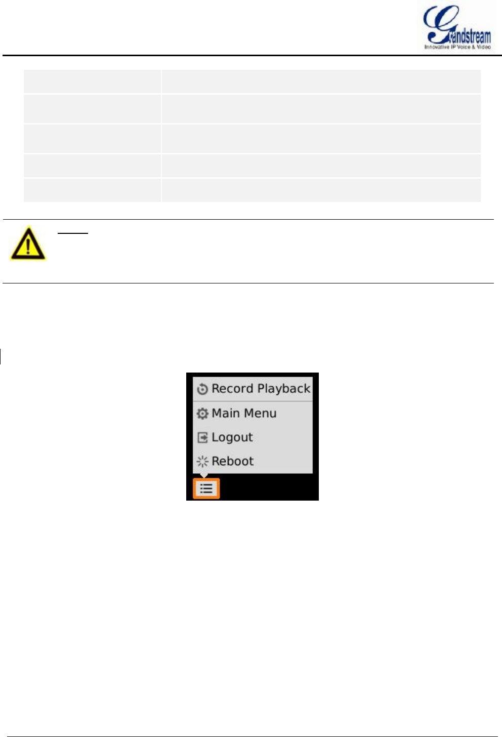
SHORTCUT BUTTON
Click on the shortcut button in the lower left corner of the preview page to bring up the shortcuts options as
shown in figure 24. Users can enter the playback page or the main menu, login /logout or reboot the device.
Figure 24 Preview Page Shortcut Button Menu
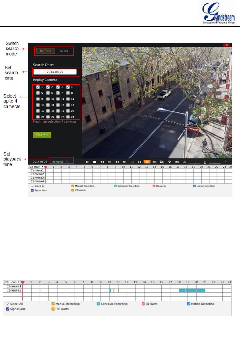
LOCAL PLAYBACK
Click right mouse and select Video Playback to enter the playback page, as shown in figure 25. Users could
make operations like Search, Playback, Tagging, Start Clipping, etc.
GVR3550/GVR3552 User Manual Page 48 of 125
Figure 25 Video Playback Page
SEARCH RECORD
Users could search video by time or by tag.
SEARCH BY TIME
Select camera (up to 4 cameras the same time) after selecting the recording date, then click the "Search"
button to search. The matching video would be displayed in the status toolbar as shown in figure 26.
Figure 26 Video Playback—Video Status Toolbar
GVR3550/GVR3552 User Manual Page 49 of 125
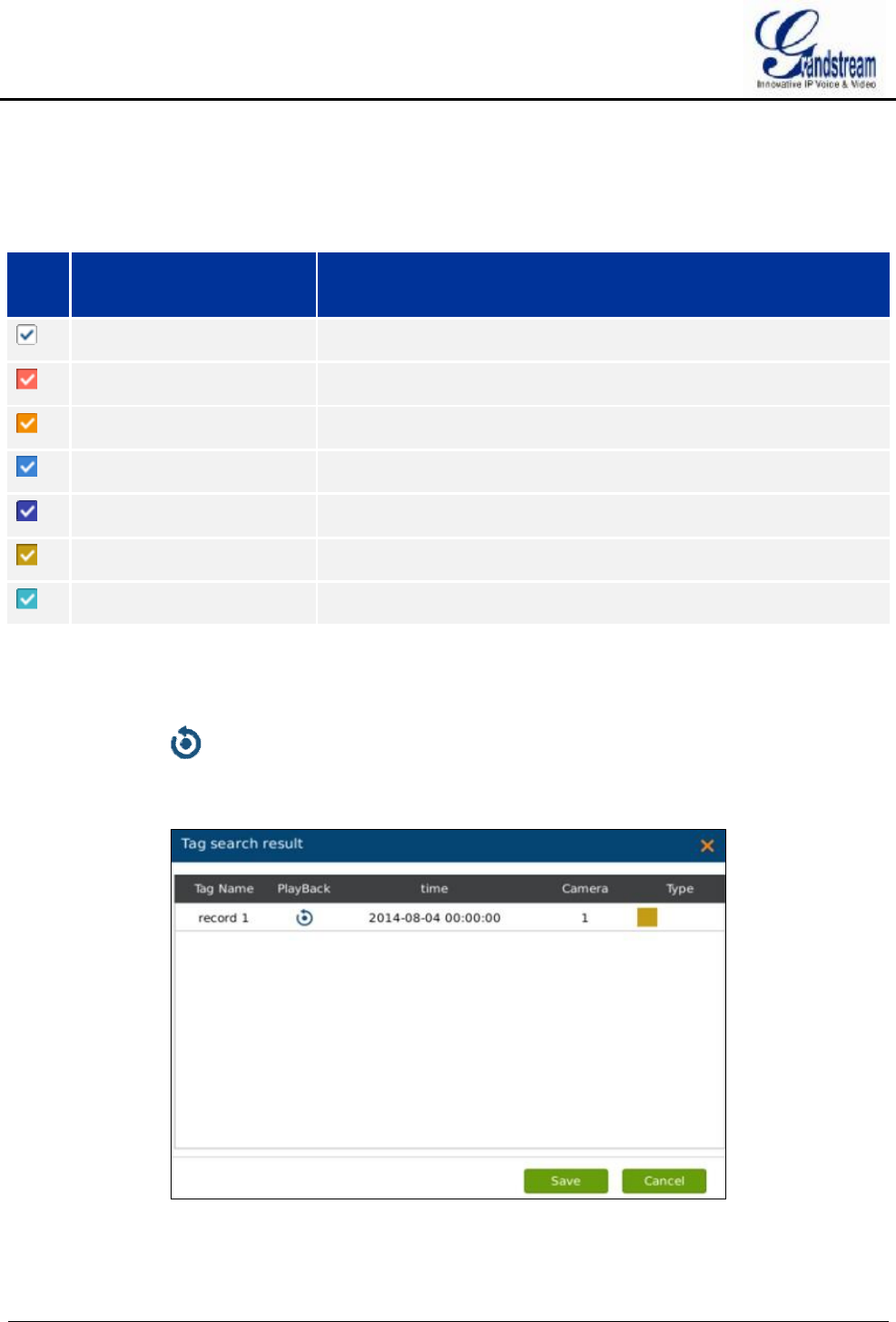
There are color descriptions about the video status on the bottom. As figure 26 shows, the video with higher
priority will be displayed on top with marked colors. Select "Search by Time" and click the check boxes with
different colors to set whether to display the corresponding video.
Table 17 Video Status Parameters Explanation
Icon
Name Explanation
Select All Display all recording types
IO Alarm Marked as IO alarm video file on GVR
IO Alarm (IPC) Marked as IO alarm (IPC) video file on GVR
Motion Detection Marked as motion detection video file on GVR
Singal Loss Marked as signal Loss video file on GVR
Manual Recording Marked as manual recording file on GVR
Schedule Recording Marked as schedule recording file on GVR
SEARCH BY TAG
Select "by Tag" and input the keyword in the search query box, click "Search" to bring up the page as shown
in figure 27. Click to playback. The color in "Type" option represents video types as the same function
on video playback page.
Figure 27 Video Playback—Search by Tag
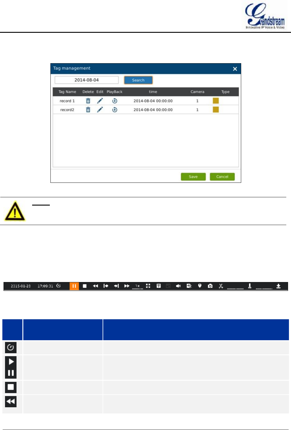
GVR3550/GVR3552 User Manual Page 50 of 125
Click "Tag Management" button to access the Tag Management page as shown in figure 28, users could edit
or delete tag(s).
Figure 28 Tag Management Page
NOTE:
Ø When HDD is full, the corresponding tag will be deleted.
VIDEO PLAYBACK
GVR3550/GVR3552 support synchronous 4 cameras playback, users can specify the camera and playback
date, or make operations like rewind, single frame rewind/ forward, capture, tagging, etc.
The playback toolbar is shown in figure 29.
Figure 29 Video Playback Toolbar
Table 18 Video Playback Toolbar Explanation
Icon
Name Explanation
Manual Set Time Click to enter the time setting page to set when to play video.
Play/Pause Play/pause video.
Stop Stop playing video.
Rewind Play backward at certain speed, only available when being played by
single camera.
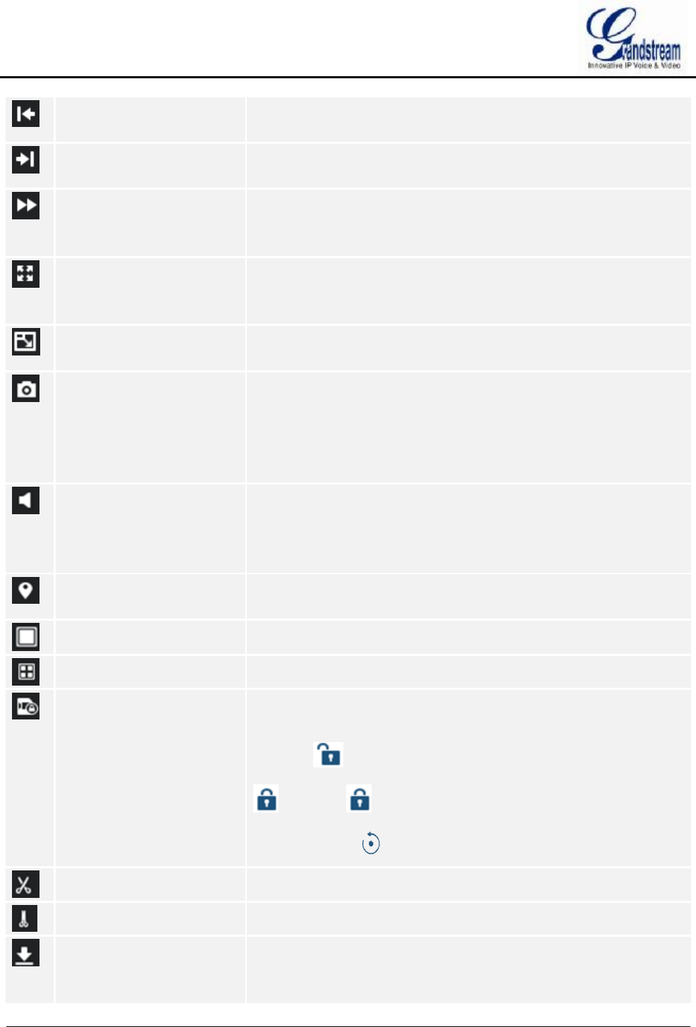
GVR3550/GVR3552 User Manual Page 51 of 125
Single Frame Rewind Single frame play backward, only available when being played by
single camera.
Single Frame Forward Single frame play forward, only available when being played by single
camera.
Speed Adjustment To adjust playback speed, support 2 times, 4 times, 8 times, 16
times, 1 time, 1/2 time, 1/4 time, 1/8 time and 1/16 time fast forward.
Only available being played by single camera.
Full Screen To enter fullscreen mode. Click the screen to bring up the toolbar on
the bottom of screen. The mouse located outside the toolbar without
any operations in three seconds would be hidden automatically.
Digital Zoom Only available being played by single camera. Click to enter PIP
screen and the lower right corner will display the main screen.
Capture Snapshot the current screen and save the image to the external
storage device. Please insert the USB device then go to Main
Menu->System Settings->Basic System Settings to set the save
path. If there is no USB device, the capture will be fail, a prompt will
be shown as in figure 30.
Volume Click the button to bring up the volume control bar, drag the slider to
adjust the volume. Click the button again to close the control bar.
Volume playback is only available when one window is being played
at normal speed.
Tagging Click the button to bring up the tagging page as shown in figure 31.
Fill in the "Tag Name" input box and then click the "Save" button.
1 Window Click one window to display.
4 Windows Click to enter 4 windows .
Locked Video Click the button to enter Locked Recording page as shown in Figure
32. Users could preview all videos and the locked videos of the day.
Click oN to lock video and the locked video is labeled with icon
, click on to unlock video. Users could also click on the
playback button to playback video.
Start Clipping Click the button to set the current play time as clipping start time.
End Clipping Click the button to set the current play time as clipping end time.
Download Clippings Click the button to bring up the video save path Setting page as
shown in figure 33 below. Click on the "Save" button to download
video after setting the path.
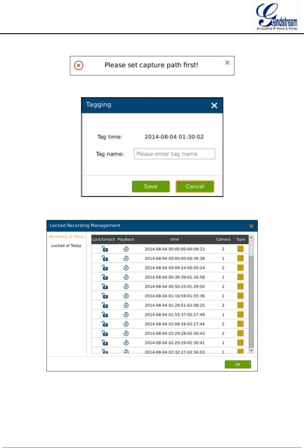
GVR3550/GVR3552 User Manual Page 52 of 125
Figure 30 Save Snapshot Failed Prompt
Figure 31 Tagging Management Page
Figure 32 Locked Video Management Page
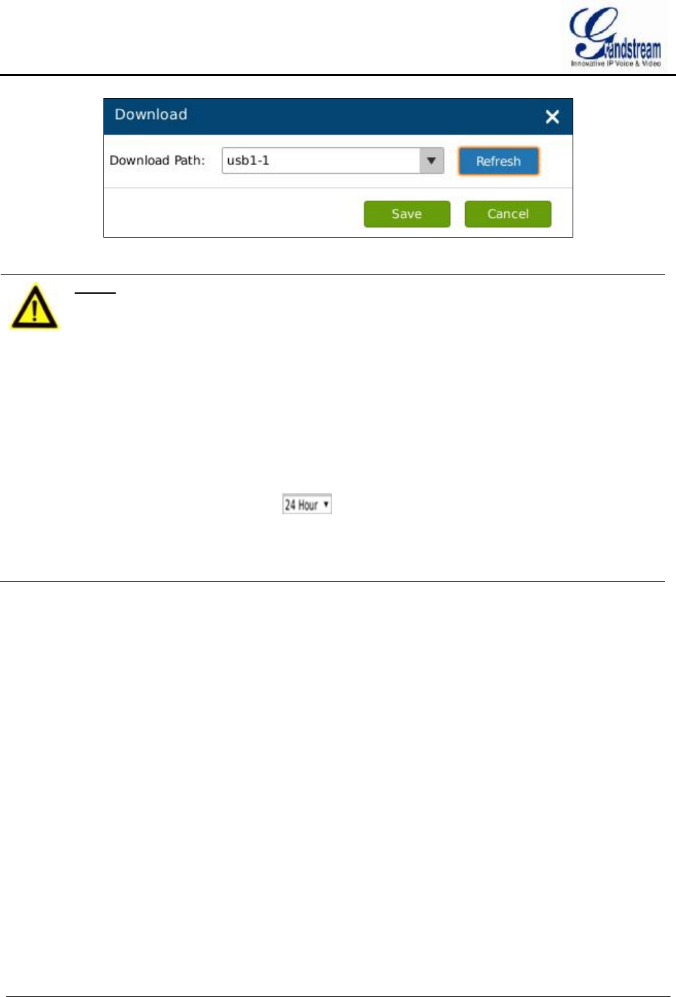
GVR3550/GVR3552 User Manual Page 53 of 125
Figure 33 Video Save Path Setting Page
NOTE:
Ø The default path would be invalid if the external storage device is changed, the
corresponding failure prompt would pop up if users click the "Capture" or
"Download" button. Users could go to Main Menu->System Settings->Basic
System Settings to set the default path to save snapshots and download file.
Ø Please do not disconnect the USB device when downloading the clipping files or
it may cause download failure or error.
Ø High camera parameters may cause insufficient GVR performance; it will
automatically stop playback and alarm. When performance returns to normal,
you can replay again.
Ø Users could click to set time range: 3 hours, 6 hours or 12 hours. Click
one time slot to replay the video.
Ø Click the time bar to playback video at one certain time.
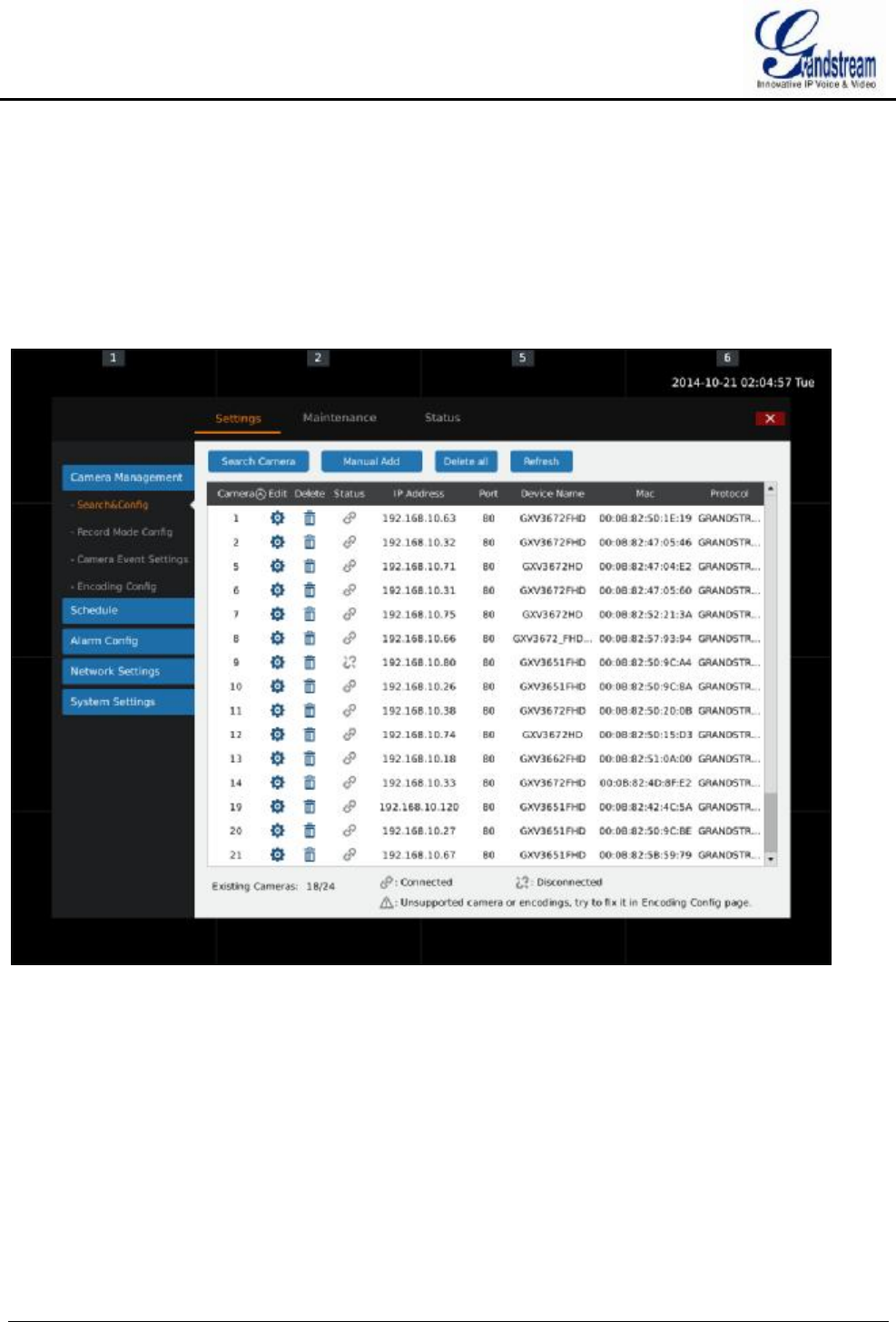
GVR3550/GVR3552 User Manual Page 54 of 125
MAIN MENU
Right click the mouse to enter GVR3550/GVR3552 main menu page, see figure 34.
Figure 34 Main Menu Page
The configuration items varied based on different user authority. Administrator users have access to Settings,
Maintenance and Status page.
SETTINGS
CAMERA MANAGEMENT
Camera management includes Search & Config, Record Mode Config, Camera Event Settings and Encoding
Config.
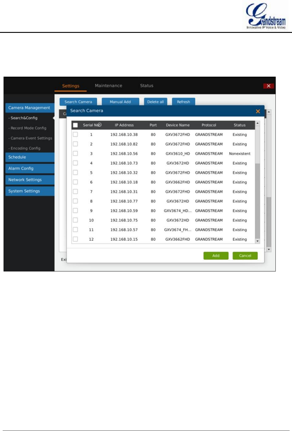
GVR3550/GVR3552 User Manual Page 55 of 125
SEARCH & CONFIG
Click on "Search Camera" button to search out all available cameras within the same LAN as shown in
figure 35.
Figure 35 Search Camera Page
Check the camera and click on "Add" button to add it to the camera list.
If unable to search out the camera you need automatically, users could manual add the camera to the camera
list. See figure 36.
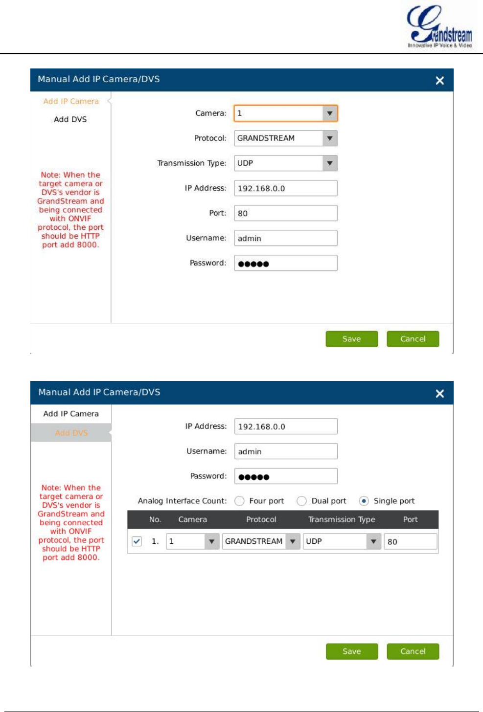
GVR3550/GVR3552 User Manual Page 56 of 125
Figure 36 Manual Add Camera Page—Add Camera
GVR3550/GVR3552 User Manual Page 57 of 125
Figure 37 Manual Add Camera Page—Add DVS
Table 19 Camera Parameters Setting Explanation
Parameter Explanation
Camera Select camera. You cannot select the existing camera.
Protocol Supports Grandstream series cameras and cameras compatible with ONVIF
protocol.
Protocol (IP) Set the protocol to TCP or UDP.
IP Address Set the IP address of the remote IP camera.
Port Set the port number of the remote IP camera. The default is "80".
Username Set the username to connect the remote IP camera. The default is "admin".
Password Set the password to connect the remote IP camera. The default is "admin".
NOTE:
Ø When trying to connect to the remote IP camera, the username and password
the GVR3550/GVR3552 use are both default, if not, the connection may fail.
Please manual modify the remote IP camera username and password.
Table 20 DVS Parameters Setting Explanation
Parameter Explanation
IP Address Set the IP address of the DVS device.
Username Set the username to connect the DVS device. The default is "admin".
Password Set the password to connect the DVS device. The default is "admin".
Analog Interface
Count
Configures DVS analog interface count. You could see the list of interfaces if there
exist more than one interface.
RECORD MODE CONFIG
Record Mode Configuration page is as shown in figure 36, users could click one camera to set Close Record,
All Day Record and Schedule Record.
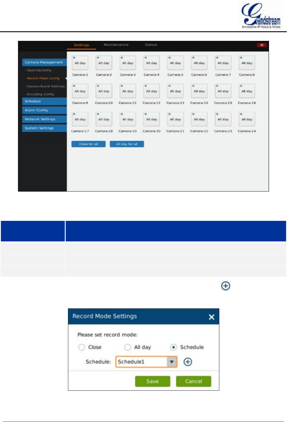
GVR3550/GVR3552 User Manual Page 58 of 125
Figure 38 Record Mode Config Page
Table 21 Record Mode Config Parameters Explanation
Parameter Explanation
All Day Record Enable all cameras to record all day.
Schedule Record Enable auto record.
Close Record Stop record.
When set to "Schedule", users should select schedule in the drop-down list. Tap on to add new schedule
or Go to Settings->Schedule->Schedule Config->New Schedule to add.
Figure 39 Record Mode Settings Page
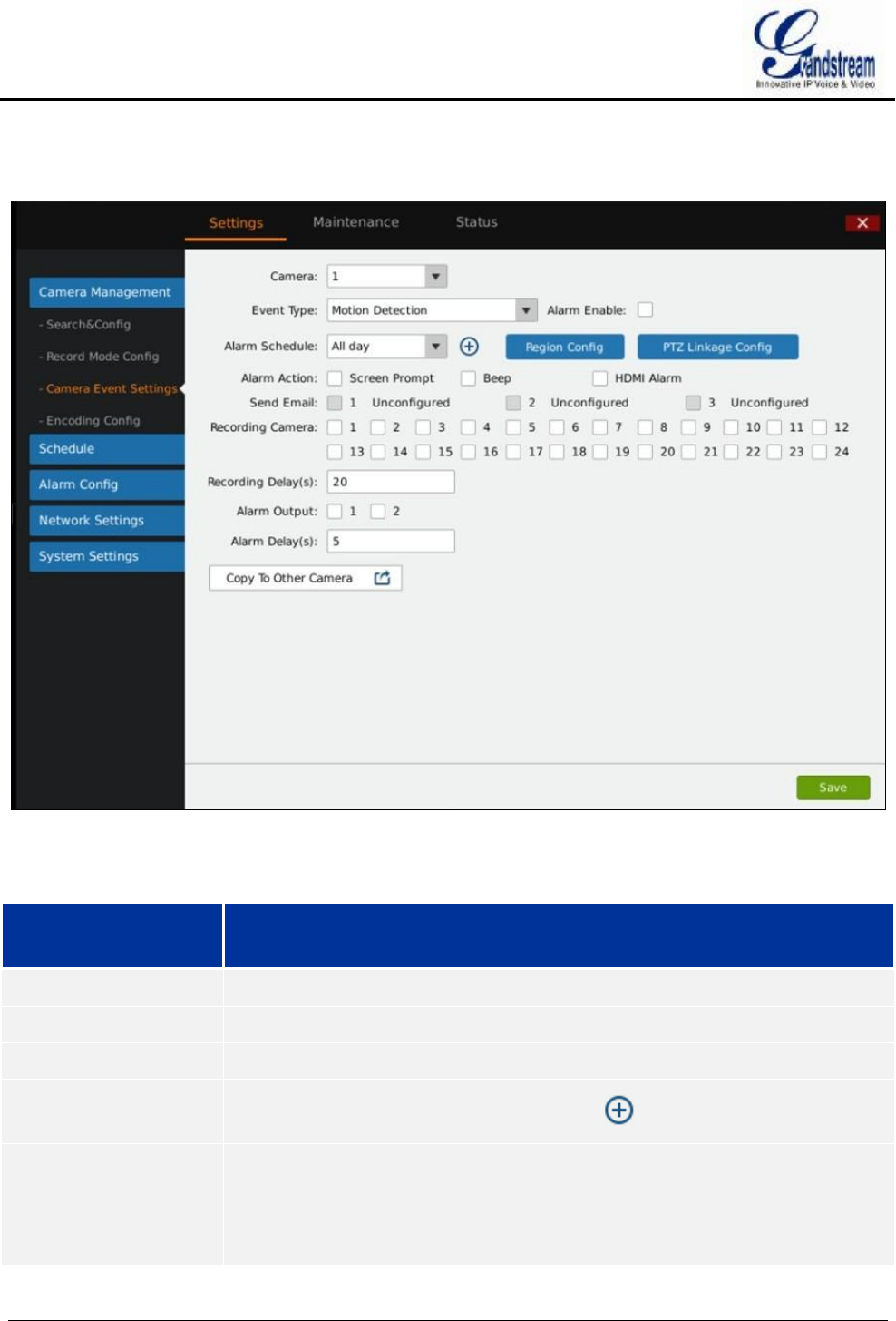
GVR3550/GVR3552 User Manual Page 59 of 125
CAMERA EVENT SETTINGS
Camera event settings page is as shown in figure 40, Users could set different alarm types to each camera.
Figure 40 Camera Event Settings Page
Table 22 Camera Events Settings parameters Explanation
Parameter Explanation
Camera Select camera.
Event Type Motion Detection, Signal Loss, IPC External Alarm.
Alarm Enable Check to enable/unable alarm.
Alarm Schedule
Select schedule in the drop-down list. Tap on to add a schedule.
Region Config Set detection area to IPC with motion detection function. Users could set up to 16
areas. Click left mouse to draw an area, then release the mouse to confirm. Click
on "X" in the upper right corner of the area to delete it, Double click or right click
mouse to save the area and exit.

GVR3550/GVR3552 User Manual Page 60 of 125
PTZ Linkage Config Only available to camera with PTZ linkage function. For different camera and
event type, users could set various alarms: Screen Prompt, Beep, HDMI Alarm,
Send Mail, Alarm Output, Alarm Delay (s), or copy the alarm to other cameras.
Alarm Action Set different alarm mode.
Table 23 Camera Alarm Parameters Explanation
Parameter Explanation
Screen Prompt Display prompt on screen when alarm.
Beep Beep when alarm.
HDMI Alarm Alarm If the GVR is connected to an HDMI display device.
Send Email Send email to one mailbox when alarm. Go to Settings ->System Settings ->
Email Settings to set.
Recording Camera Select camera to record when alarm.
Record Delay (s) When the alarm end, the alarm recording will last for a period of time before stops,
the range is 10~180 seconds.
Alarm Output The alarm output interface when alarm.
Alarm Delay (s) When the alarm end, the alarm output will last for a period of time before stops,
the range is 1~600 seconds.
Copy to Other Camera Copy the alarm parameters of one camera to other cameras.
ENCODING CONFIG
Encoding Config page is as shown in figure 41.
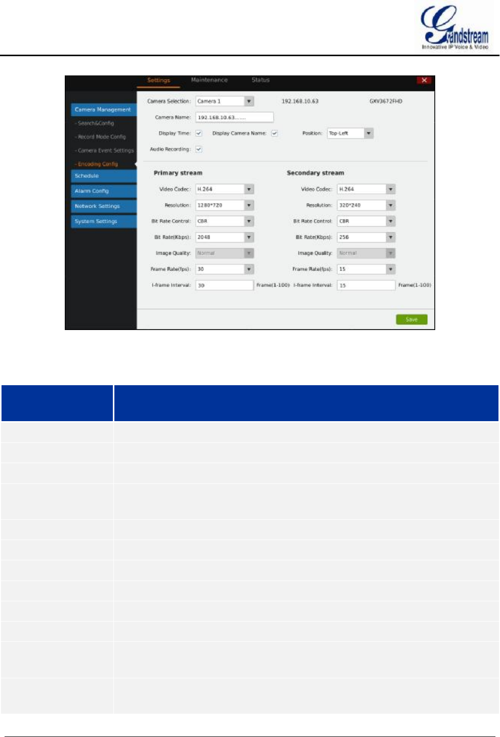
GVR3550/GVR3552 User Manual Page 61 of 125
Figure 41 Encoding Config Page
Table 24 Encoding Config Parameters Explanation
Parameter Explanation
Camera Selection Select camera. Once selected, it will display the camera’s IP and model.
Camera Name Display camera name on preview screen.
Display Time Defines whether to display time on preview screen.
Display Camera
Name
Defines whether to display camera time on preview screen.
Position Displaying camera’s name and time on Top-Left or Bottom-Left on preview screen.
Audio Recording Defines whether to record audio when recording.
Primary Stream Configure parameters.
Secondary Stream Configure parameters.
Video Codec Select the Codec the camera supports. Beta version just supports H.264.
Resolution Configure the resolution for each camera. Supports no more than 1920*1080P.
Bit Rate Control When set to CBR, the image quality is inalterable; If set to VBR, configure the image
quality based on the range the camera provides.
Image Quality When the bite rate is set to VBR, configure the image quality based on the range the
camera provides.
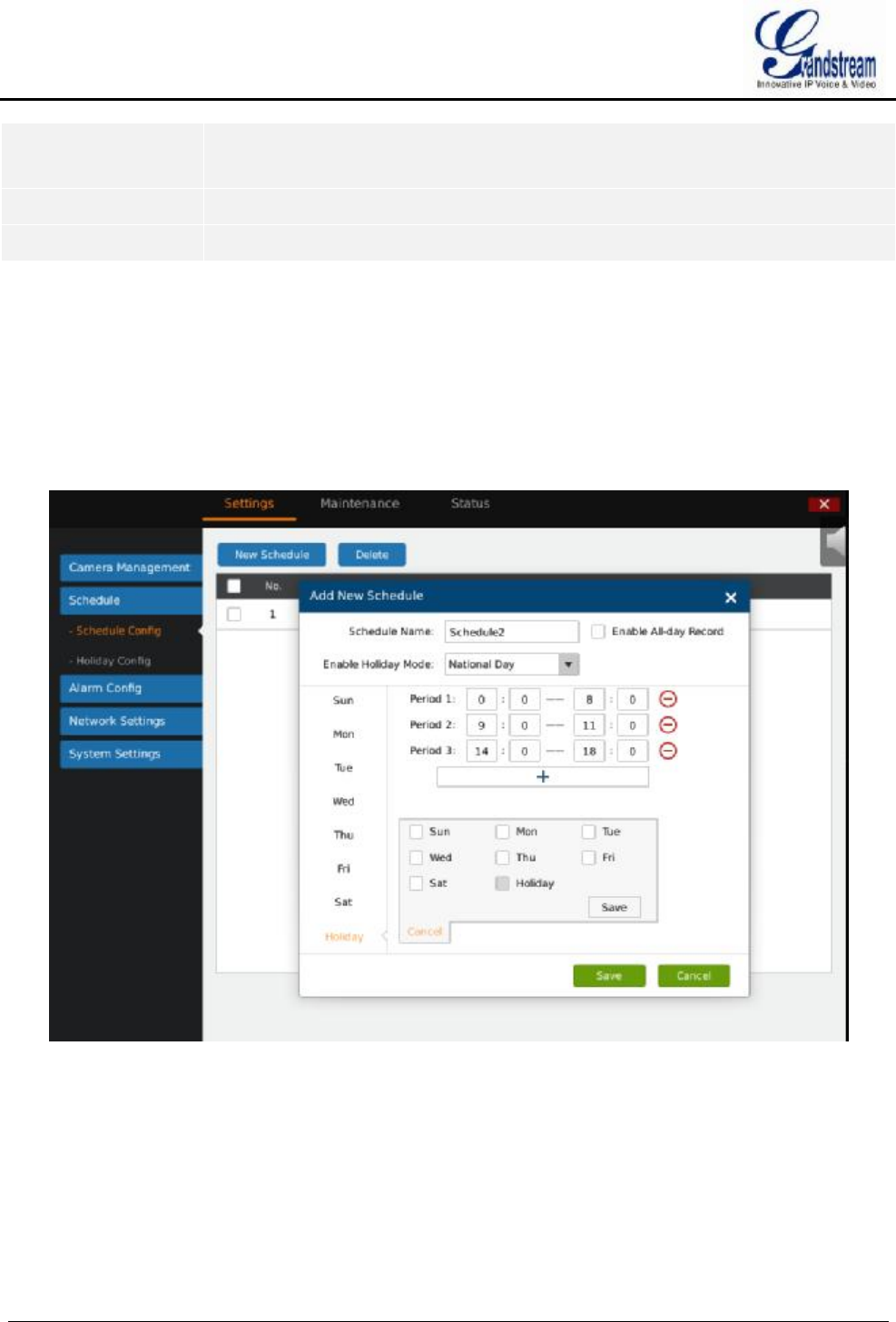
GVR3550/GVR3552 User Manual Page 62 of 125
Bit Rate (kpbs) Set the bite rate to change image quality, greater bit rate brings better image quality.
The range is 256~8192Kbps.
Frame Rate (fps) The range is1~30fps or auto.
I - frame Interval The range is 1~100s.
SCHEDULE
SCHEDULE CONFIG
Users could add new schedule and manage schedule record and alarm event of each camera. Users could add
up to 16 schedules, see figure 42.
Figure 42 Schedule Config Page
ADD SCHEDULE
Follow the steps below to add schedule.
1. Tap on "New Schedule” and input schedule name in figure 43.
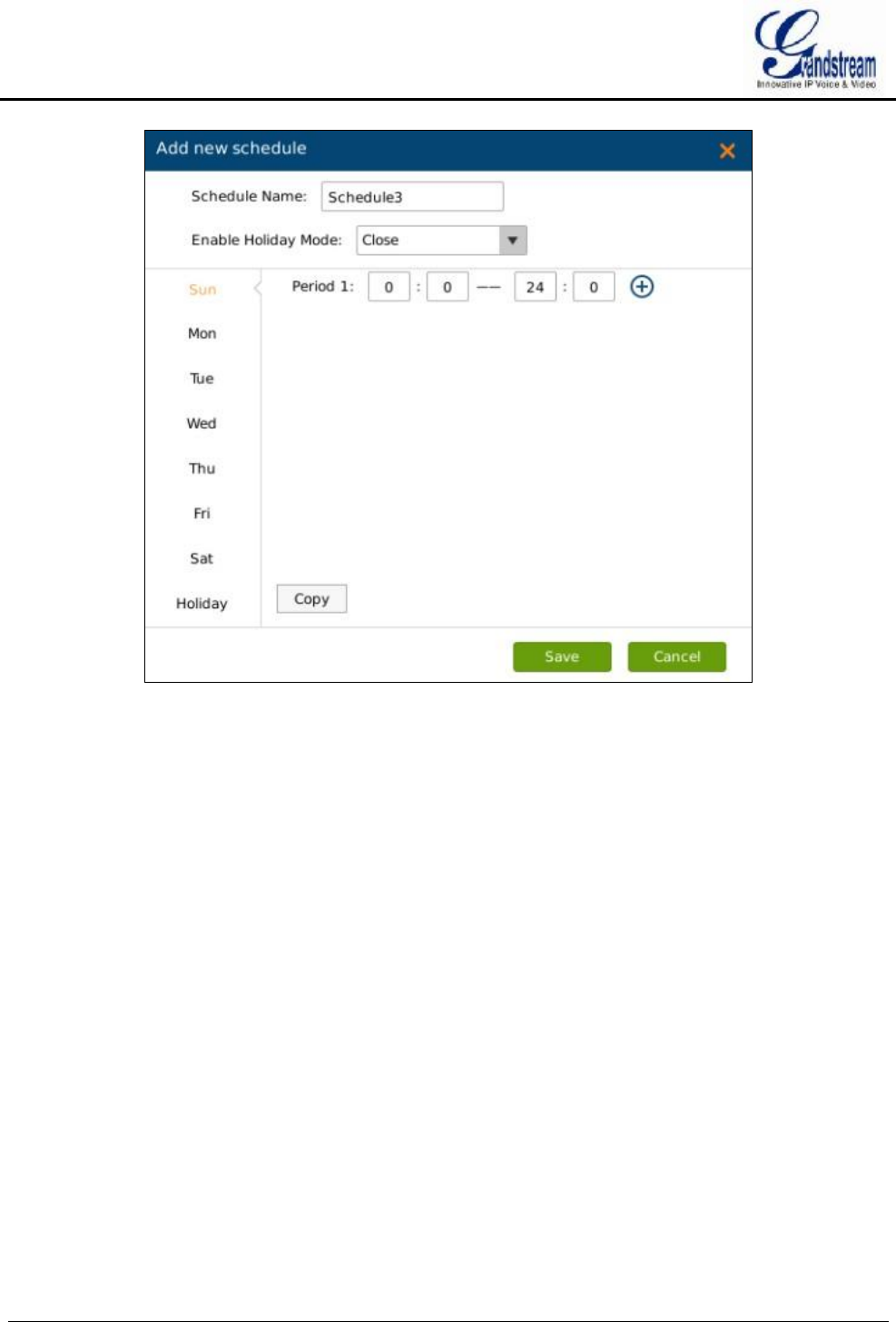
GVR3550/GVR3552 User Manual Page 63 of 125
Figure 43 Add New Schedule Page
2. Schedule on weekly basis: at least set one period and you could set up to 16 periods. Users could copy
the periods of one week to other weeks. See Figure 44.
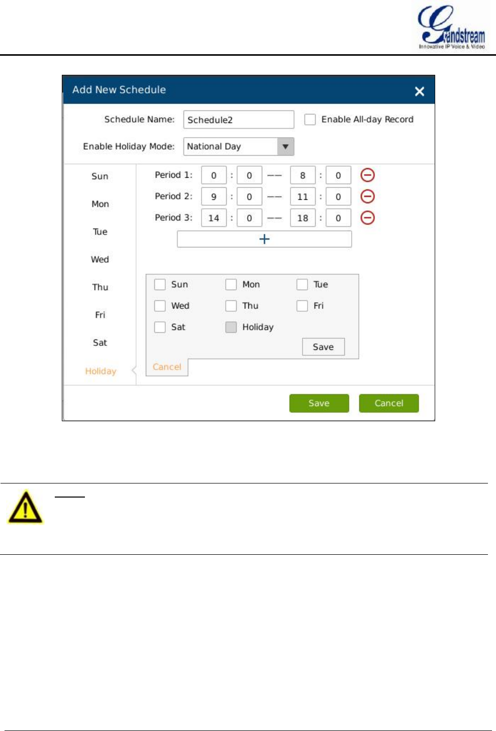
GVR3550/GVR3552 User Manual Page 64 of 125
Figure 44 Schedule Config—Add New Schedule—Copy to Other Period
3. Select "Enable Holiday mode" if you want to use the schedule on holidays
4. Click on "Save".
NOTE:
Ø If select "Enable All-day Record", record all day except the periods on holiday
mode.
Ø Please configure holiday first if you want to use "Enable Holiday mode". Please
refer to Holiday Config Chapter for more details.
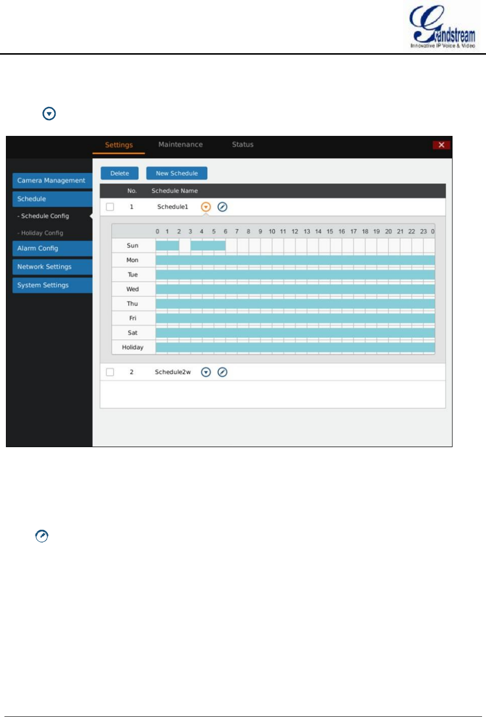
GVR3550/GVR3552 User Manual Page 65 of 125
VIEW SCHEDULE
Tap on behind schedule to view details. Tap the icon again to hide the status bar.
Figure 45 Schedule Details Page
EDIT SCHEDULE
Click to access the schedule editing page.
DELETE SCHEDULE
Supports batch delete. Tap on "delete" button to batch select and delete.
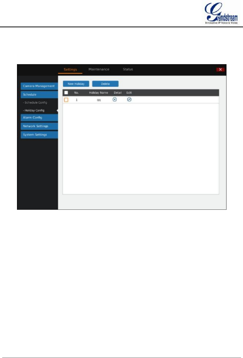
GVR3550/GVR3552 User Manual Page 66 of 125
HOLIDAY CONFIG
Users could add new holiday and manage holidays on this page. Users could add up to 16 holidays, see
figure 46.
Figure 46 Holiday Config Page
ADD NEW HOLIDAY
1. Click "New Holiday" to bring up the page as shown in figure 47. Users could input holiday name.
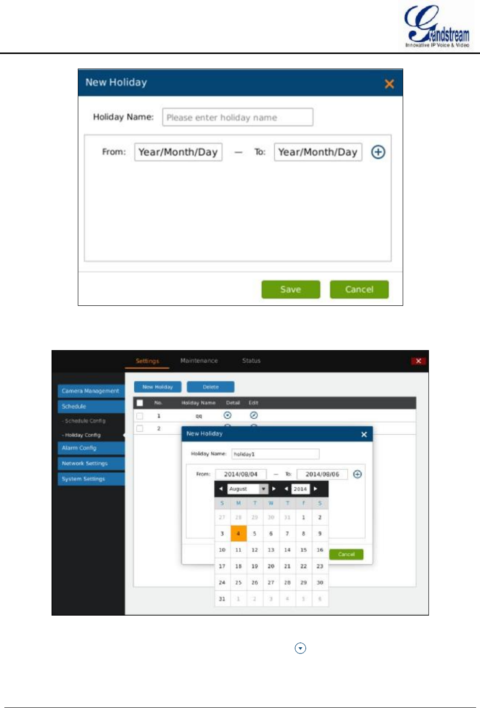
GVR3550/GVR3552 User Manual Page 67 of 125
Figure 47 Add New Holiday Page
2. Set holiday starting time and end time. Users could add up to 32 periods. See figure 48.
Figure 48 Add New Holiday Editing Page
Users could edit, modify, delete schedule in the holiday list. Click to view the holiday details.
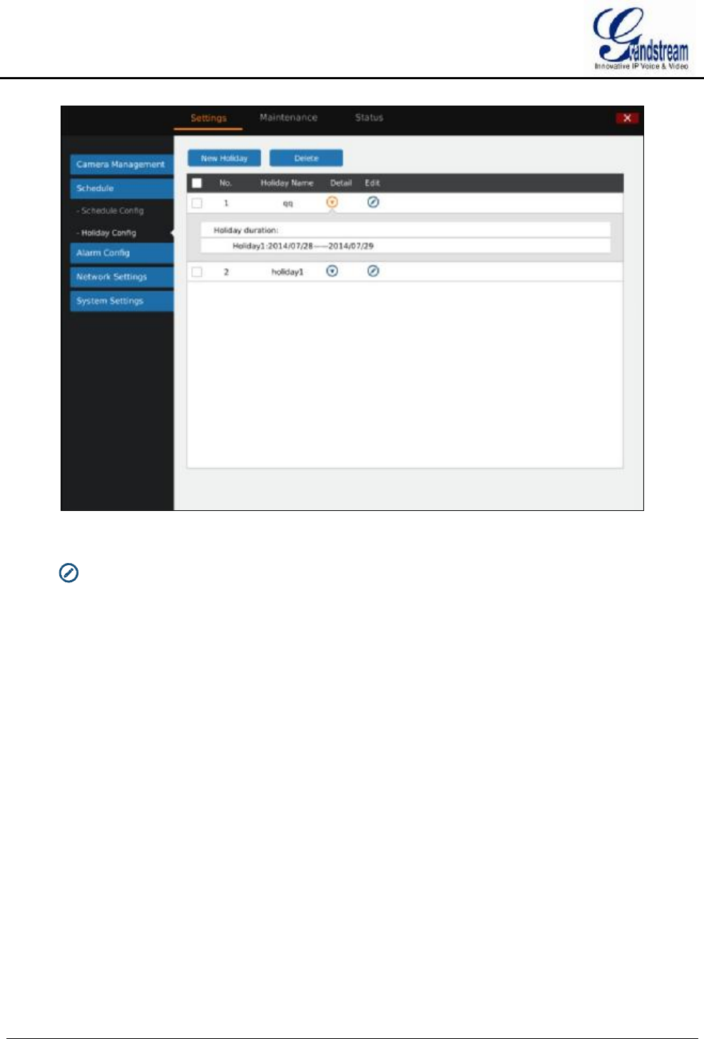
GVR3550/GVR3552 User Manual Page 68 of 125
Figure 49 Holiday Details Page
Click to bring up the holiday editing page.
ALARM CONFIG
Please refer to the chapter Connect Alarm Device to connect the output and input devices.
IO ALARM CONFIG
Users could set different alarm type to each alarm input, see figure 50.
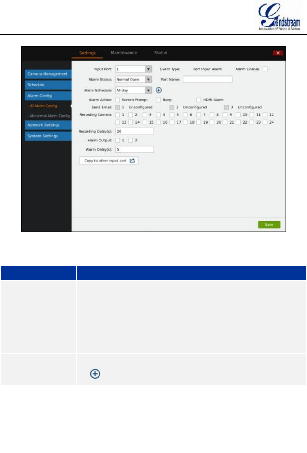
GVR3550/GVR3552 User Manual Page 69 of 125
Figure 50 IO Alarm Config Page
Table 25 IO Alarm Config Parameters Explanation
Parameter Explanation
Input Port Select the input port.
Event Type Select the event type.
Alarm Enable Check to enable/disable alarm.
Alarm Status Set alarm status. Normally Open (default) and Normally Close are two available
options. Please choose the status according to your alarm type.
Port Name Enter port name for users to distinguish different input ports.
Alarm Schedule Select alarm schedule in the drop-down list. If there is no existing schedule, click
on to add new schedule. The alarm only available in schedules.
Users could set various alarm linkages according to different alarm such as Screen Prompt, Beeper, HDMI
Alarm, Send Email, or Copy Alarm to Other Cameras. The Parameters settings are the same in chapter
Camera Event Settings.
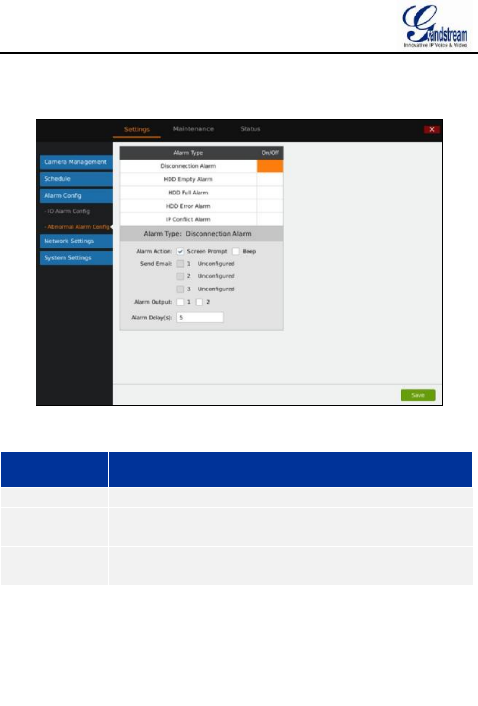
GVR3550/GVR3552 User Manual Page 70 of 125
ABNORMAL ALARM CONFIG
Abnormal Alarm Config includes Disconnection Alarm, HDD Empty Alarm, HDD Full Alarm, HDD Error
Alarm and IP Conflict Alarm. See figure 51. Users can set alarm linkages to different alarm types.
Figure 51 Abnormal Alarm Config Page
Table 26 Abnormal Alarm Parameters Explanation
Parameter Explanation
Disconnection Alarm
Alarm when no cable access detected.
HDD Empty Alarm Alarm when no HDD access detected.
HDD Full Alarm Alarm when HDD is full.
HDD Error Alarm Alarm when detecting HDD error.
IP Conflict Alarm Alarm when the IP address is conflict with the GVR address.
NETWORK SETTINGS
Network Settings includes Basic Settings, Advanced Settings and Security Settings. Users could easily
connect to network and configure network security.
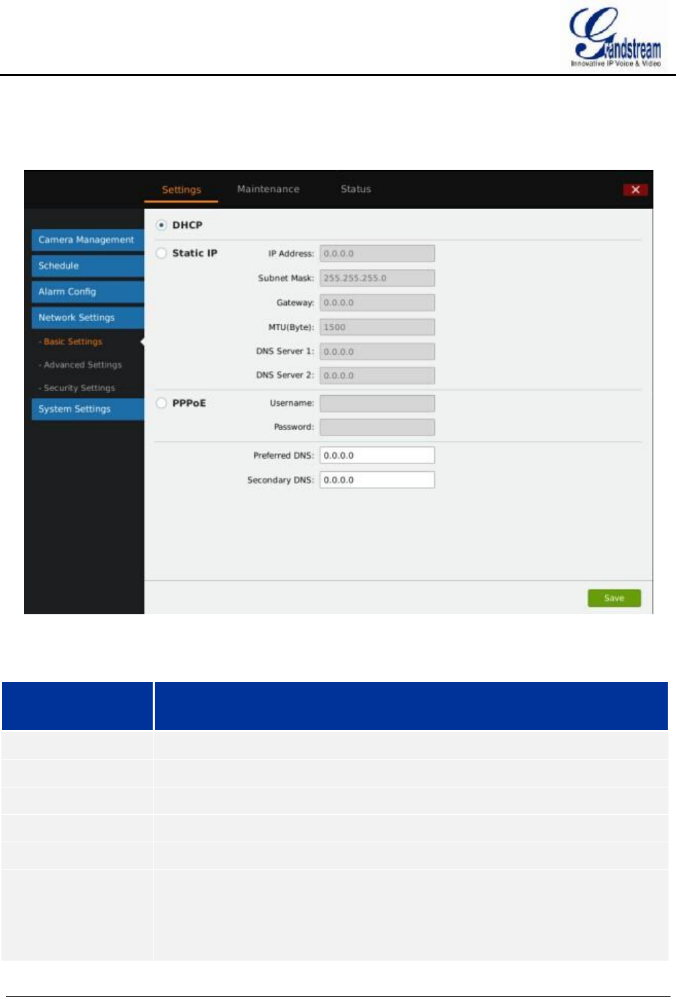
GVR3550/GVR3552 User Manual Page 71 of 125
BASIC SETTINGS
Basic Settings page is shown in figure 52, users can choose to obtain IPv4 address automatically or manual
set static IP address or use PPPoE. GVR3550 is available only when network setup is correct.
Figure 52 Network Settings—Basic Settings Page
Table 27 Basic Network Parameters Explanation
Parameter Explanation
DHCP Obtain IPV4 address from the DHCP server automatically.
Static IP Set static network parameters.
IP Address Manual enter the IPV4 address.
Subnet Mask Manual enter the IPV4 subnet mask.
Gateway Manual enter the IPV4 default gateway address.
MTU (Byte) Enter MTU (Maximum Transmission Unit), the maximum data package that can be
transmitted on the network. If the GVR MTU is greater than the one of the gateway,
the lager one will be split for transmission. Please confirm the MTU value of your
gateway before set.
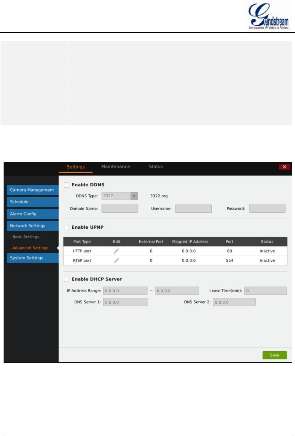
GVR3550/GVR3552 User Manual Page 72 of 125
DNS Server 1 Manual enter the DNS server 1 address.
DNS Server 2 Manual enter the DNS server 2 address.
PPPoE Check to set static network parameters
Username Manual enter the username provided by the network vendor.
Password Manual enter the password provided by the network vendor.
Preferred DNS Manual enter the preferred DNS server address.
Secondary DNS Manual enter the secondary DNS server address.
ADVANCED SETTINGS
Advanced Settings page is shown in figure 53. Users can set DDNS, UPnP and DHCP.
Figure 53 Network Settings—Advanced Settings Page
ENABLE DDNS
Enable DDNS to access the GVR if already enabled PPPoE connection, with this way can effectively solve
the problem brought by access GVR with dynamic IP.
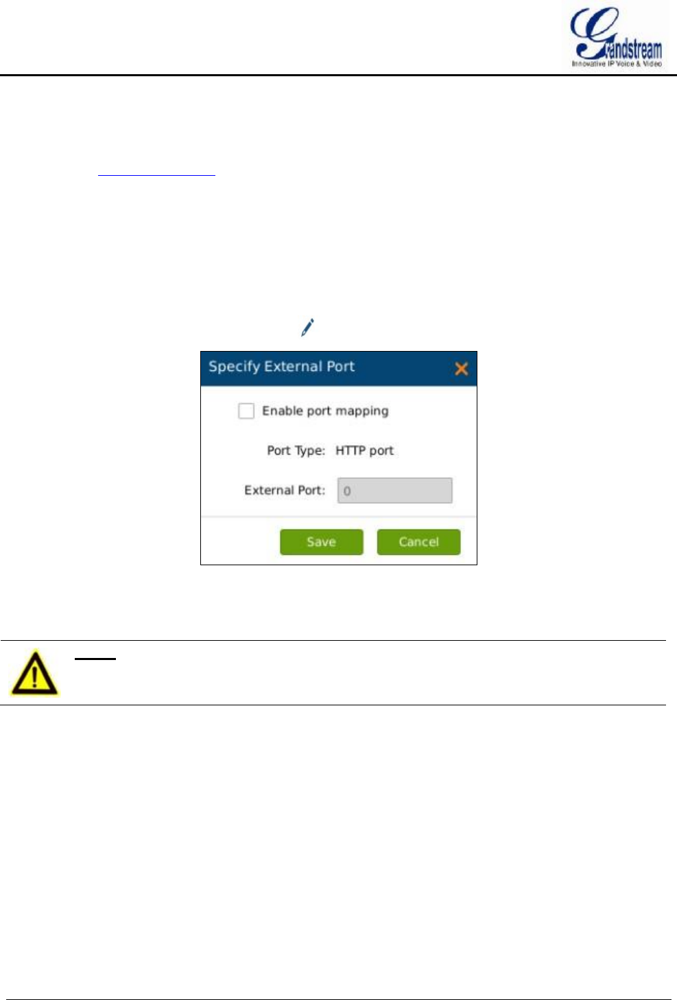
GVR3550/GVR3552 User Manual Page 73 of 125
Select the proper DDNS type (the Beta version only supports ipkan) in the drop-down list and input the
correct domain name, username and password to complete the DDNS settings.
In order to access GVR via internet, you also need to enable UPnP and set port. If the DDNS type you select
is ipkan, go to www.ipkan.com.cn to register username and password. Upon successful registration you can
fill in the username and password on DDNS Settings interface.
ENABLE UPnP
The full name of UPnP is Universal plug-in and Play, enable NAT of UPnP to realize auto port mapping thus
allows external computer to access intranet to enhance network efficiency.
After checking "Enable UPnP", users can click to set external port, as shown in figure 54.
Figure 54 Specify UPnP External Port Page
When the port status displays "Active", it indicates the successful connection of the GVR and the router, the
parameters have taken effect.
NOTE:
Ø The port sequence should correspond to the router list.
ENABLE DHCP SERVER
GVR3550/GVR3552 could allocate dynamic IP address to other devices within the same LAN. Follow the
procedures below to set:
1. Check "Enable DHCP Server";
2. Input the assignable IP address.
3. Input Lease Time;
4. Set DNS server address and the secondary DNS server address.
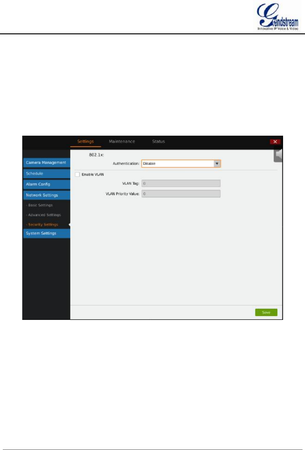
GVR3550/GVR3552 User Manual Page 74 of 125
MULTICAST GROUP
When access GVR3550 via remote network to make real-time preview, if the users access exceed the maximum
network bandwidth, users will unable to preview, set multicast IP to save the problem.
multicast IP is D type IP address, the range is 224.0.0.0~239.255.255.255. It is recommended to use address
between 239.252.0.0 and 239.255.255.255.
SECURITY SETTINGS
GVR3550/GVR3552 security settings page is as shown in figure 55.
Figure 55 Security Settings Page
802.1x MODE
GVR3550/GVR3552 supports MD5 and EAP (PEAP).
Authentication: Set whether to to enable/disable 802.1x mode. Configures 802.1x authentication identity and
other parameters when connecting to PBX. The default setting is "disabled".
When set authentication to "MD5", once enabled, the user would be required to enter the identity and MD5
password to be authenticated on the network.
When set authentication to "Protected EAP (PEAP)", once enabled, the user would be required to upload CA
certificate and enter the identity and EAP (PEAP) password to be authenticated on the network.

GVR3550/GVR3552 User Manual Page 75 of 125
Enable VLAN
VLAN Tag: Assigns the VLAN Tag of the Layer 2 QoS packets. The default value is 0, The valid range is
0~4095.
NOTE:
Ø The port sequence should correspond to the router list.
VLAN Priority Value: Assigns the priority value of the Layer 2 QoS packets. The default value is 0, The
valid range is 0~7.
SYSTEM SETTINGS
System Settings includes Basic Settings, Date & Time, Display Settings, Local View Control, HDD
Management, etc.
BASIC SETTINGS
Basic Settings page is shown in figure 56.
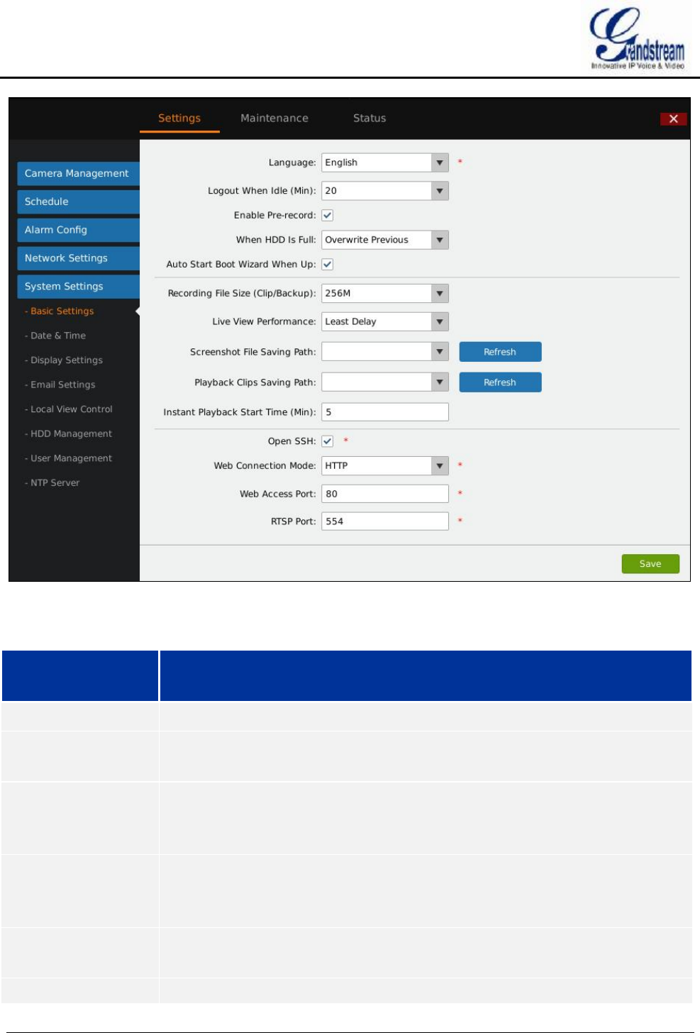
GVR3550/GVR3552 User Manual Page 76 of 125
Figure 56 System Settings Page—Basic Settings Page
Table 28 GVR3550 Basic System Setting Parameters Explanation
Parameter Explanation
Language Set the language to English or simplified Chinese.
Logout when idle
(Min)
Set the logout time when timeout. If logout, users need to login again to make
operations except preview.
Enable Pre-record (s)
Set pre-record mode. Once enabled, users could view the video images a few
seconds before alarm in alarm event. The pre-record durations vary according to
different cameras settings.
When HDD Is Full Set the record policy when HDD is full. "Overwrite Previous" means the new video
will overwrite the earliest ones when HDD is full of videos. The default setting
is "Stop Record".
Auto Start Boot
Wizard When Up
Set whether to enable wizard when boot up. Once checked, the wizard will pop up
for installation.
Recording File Size The file size of video (Clips/Backups).Users could choose 256M or 512M. The

GVR3550/GVR3552 User Manual Page 77 of 125
(Clip/Backup) default settings is 256M.
Live View
Performance
Set the preview performance to Least Delay, Best Fluency and Balanced. Least
delay emphasizes the fluency of the video while best fluency emphasizes the
real-time quality of the video. The default setting is "Least Delay".
Screenshot File
Saving Path
Set the default path to save the screenshot file when preview and playback.
Videos and Playback
Clips Save Path
Set the default path to save the clipping file when playback.
Instant Playback
Start Time (Min)
Set the start time for instant playback. The default is 5 minutes.
Open SSH Set whether to open SSH.
Web Connection
Mode
HTTP or HTTPS, the default is HTTP.
Web Access Port When set Web connection mode to HTTP, the default port is 80, the default port is
443 for HTTPS. Restart the device to make changes take effect.
RTSP Port The default is 554.
DATE & TIME
See figure 57.
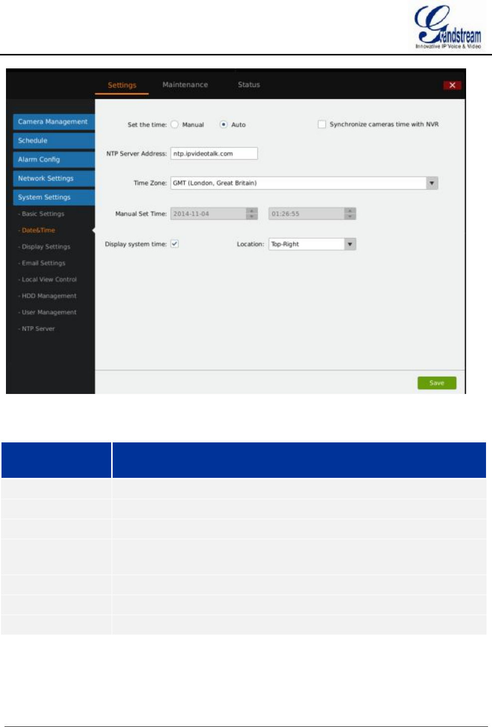
GVR3550/GVR3552 User Manual Page 78 of 125
Figure 57 System Settings Page—Date & Time
Table 29 System Settings Page—Date & Time Parameters Explanation
Parameter Explanation
Set Time Users could manual set time or obtain time from the NTP server automatically.
Manual Manual set time.
Auto Obtain time automatically from NTP server.
Synchronize Camera
Time with NVR
Synchronize the time on GVR3550 to the connected cameras.
NTP Server Address Set NTP server to obtain time.
Time Zone Manual set time zone.
Manual set time Manual set time.
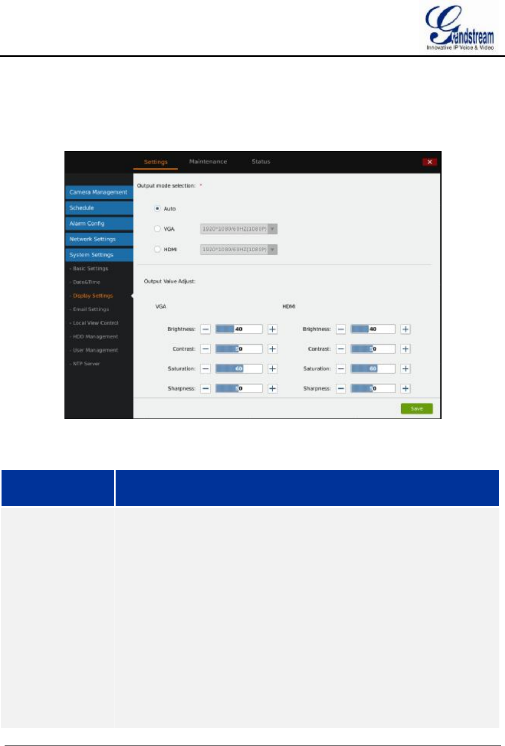
GVR3550/GVR3552 User Manual Page 79 of 125
DISPLAY SETTINGS
Users could set output mode and adjust output value like brightness, contrast, saturation, sharpness of the
connected display device.
Figure 58 System Settings Page—Display Settings
Table 30 System Settings Page—Display Settings Parameters
Parameter Explanation
Output Mode
Selection
Users could select output mode: Auto, VGA, HDMI. The default setting is "Auto".
Ÿ When set to "Auto", GVR3550 will automatically detect the display once
reboots. It could identify 1024*768 resolution on VGA display device, or
1920*1080/60HZ (1080P), 1280*720/60HZ (720P), 1920*1080/50HZ (1080P),
1280*720/50HZ (720P), 720*576/50HZ (576P), 720*480/60HZ (480P)
resolution on HDMI display device. Only identify HDMI device when
connecting to VGA and HDMI device the same time.
Ÿ When set to "VGA", configure mode according to the resolution the VGA
display device supports.
Ÿ When set to "HDMI", configure mode according to the resolution the HDMI
display device supports.
Note: If the resolution the display supports is not compatible with the one the GVR
supports, it may cause display output failure.
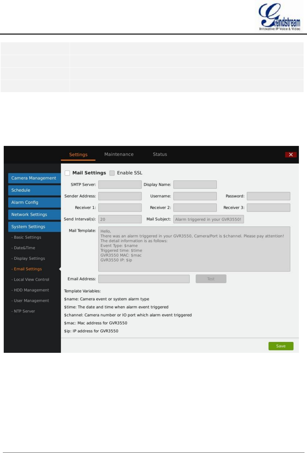
GVR3550/GVR3552 User Manual Page 80 of 125
Brightness The reference range is 0~100.
Contrast The reference range is 0~100.
Saturation The reference range is 0~100.
Sharpness The reference range is 0~100.
EMAIL SETTINGS
GVR3550/GVR3552 could end Email when triggered alarm.
Figure 59 System Settings Page—Email Settings
Follow the steps to set Email:
1. Input SMTP server address;
2. Input display name, sender address, username and password;
3. Set receiver address. GVR3550/GVR3552 could set up to 3 receiver addresses. Users could send
differ\ent alarms to different receivers;
4. Set send interval. All alarms in this interval will be sent together in one Email;
5. Input mail subject and template. Users could use default ones or custom them.
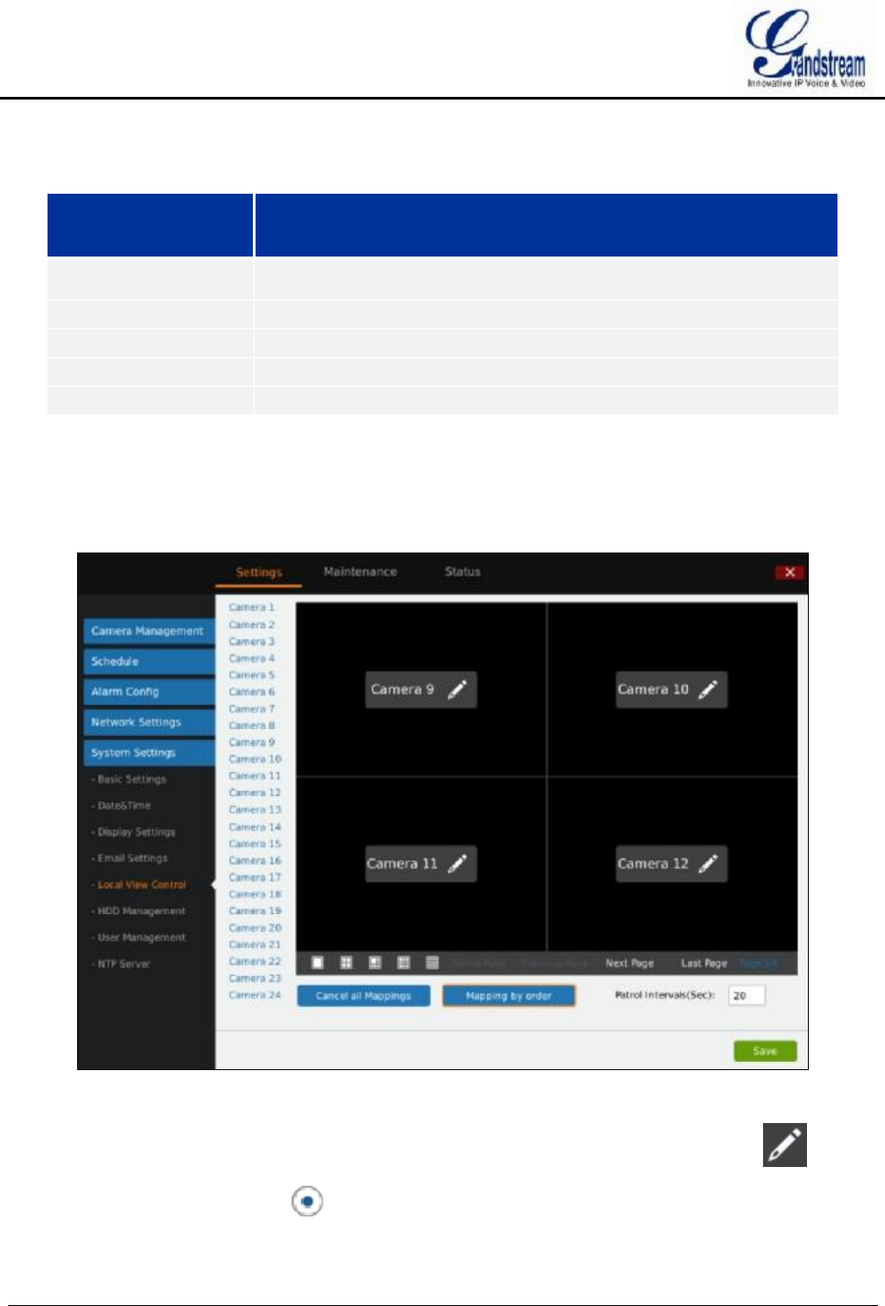
GVR3550/GVR3552 User Manual Page 81 of 125
Input email address and click on "Test" to test if the configurations are effective.
Table 31 Email Template Parameters Specifications
Key Word Explanation
$name Alarm name.
$time The time to trigger alarm.
$channel The camera to trigger alarm.
$mac MAC address of GVR3550
$ip IP address of GVR3550.
LOCAL VIEW CONTROL
Users could set cameras and patrol time intervals, as shown in figure 60.
Figure 60 System Settings Page—Local View Control
The name of connected camera ill be displayed on the left list, as shown in figure 60. Click on to
access the camera list page, check before the camera name to map the camera to certain screen as
shown in figure 61.
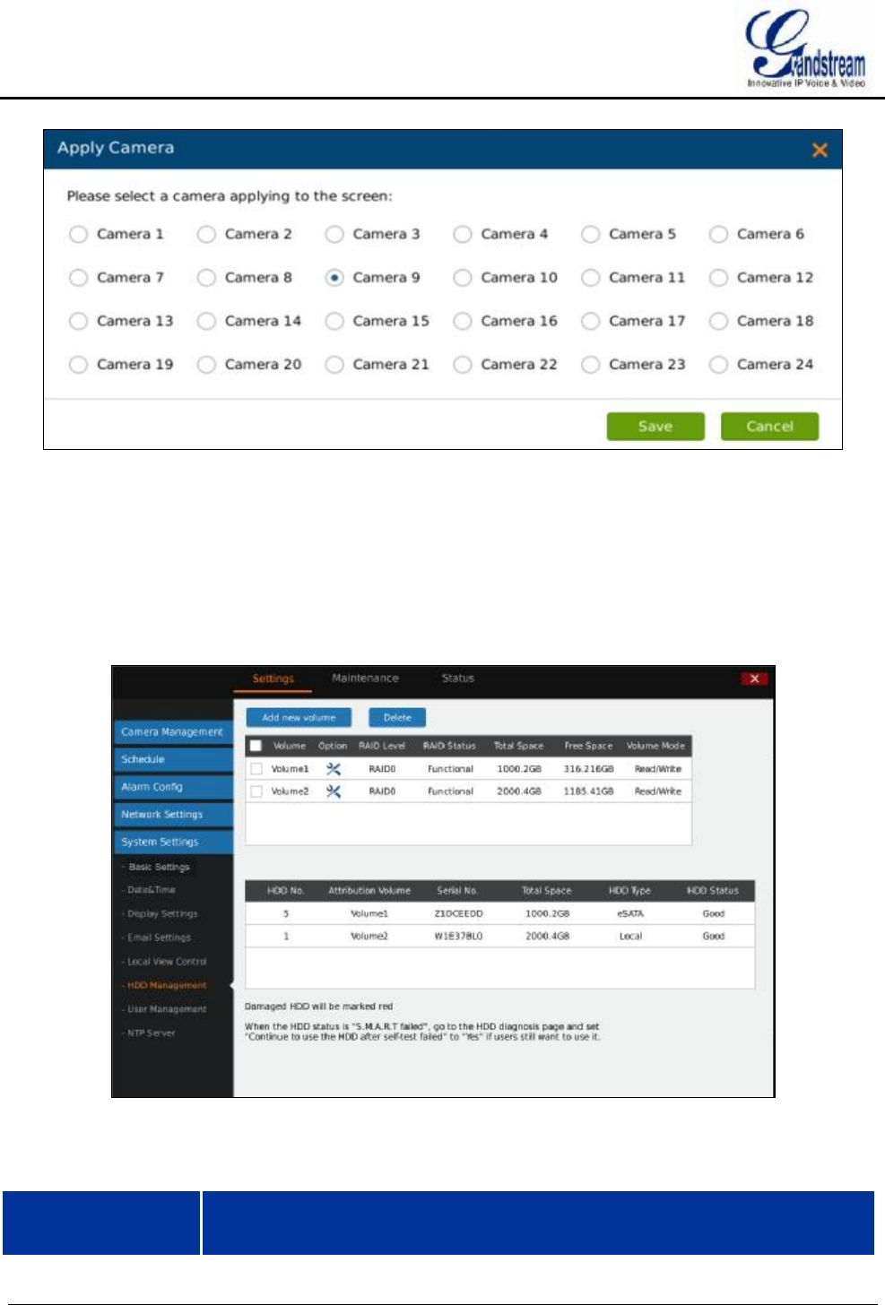
GVR3550/GVR3552 User Manual Page 82 of 125
Figure 61 Local View Control—Apply Camera
HDD MANAGEMENT
HDD Management page is shown in figure 62. Users could view each HDD storage status or format HDD,
erase data, configure attribution, etc.
Figure 62 System Settings Page—HDD Management
Table 32 System Settings Page—HDD Management Parameters Explanation
Parameter Explanation
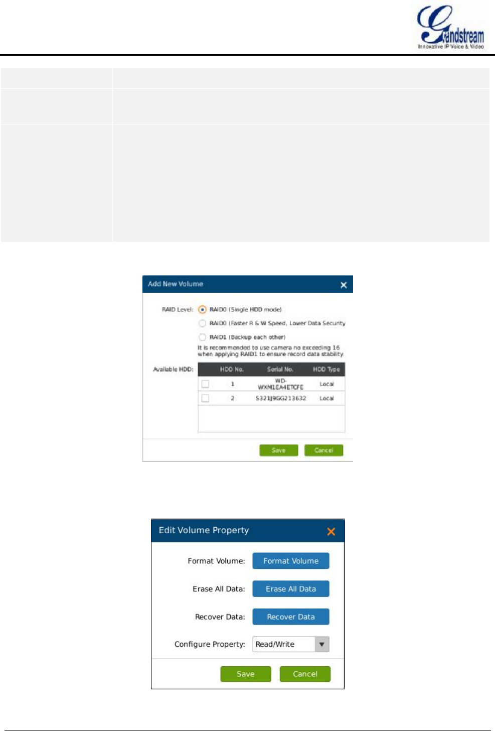
GVR3550/GVR3552 User Manual Page 83 of 125
Add New Volume Access the detail page to set volume.
Delete Delete existing volume. Please consider carefully before apply. Once deleted, the
volume data will be all erased and could not be restored.
RAID Level Ÿ RAID0 (Single HDD mode): To increase the reliability of HDD data. When an
error occurs on file storage system, the HDD data could be restored.
Ÿ RAID0 (Faster R & W speed, lower data security): Low security. Set two HDD
(s) or more to RAID0, users could get the fastest read-write speed but cannot
restore HDD data once an error occurs.
Ÿ RAID1 (HDD backup each other): Full backup data. It requires at least two
HDD (s) and the camera should not more than 16.
Add New Volume page is shown in figure 63.
Figure 63 HDD Management—Add new Volume
Edit Volume Property page is shown in figure 64.
Figure 64 HDD Management—Edit Volume Property

GVR3550/GVR3552 User Manual Page 84 of 125
NOTE:
Ø It is recommended to add no more than 16 cameras to guarantee video data
stability when using RAID1.
Ø It is recommended not to use RAID0 and RAID1 the same time.
Table 33 Edit Volume Property Parameters Explanation
Parameter Explanation
Format Volume Users could format the existing volume, please consider carefully before apply.
Once formatted, the volume data will be all erased and could not be restored.
Erase All Data Users could erase all data of the existing volume, please consider carefully before
apply. Once formatted, the volume data will be all erased and could not be restored
other than the locked record.
Recover Data Recover data when RAID is abnormal.
Configure Property Set the property of existing volume to Read-Write or Read-only. The volume will
not save video if set to Read-only.
USER MANAGEMENT
GVR3550 could add up to 30 users .Users can be operator or normal user. As shown in figure 65.
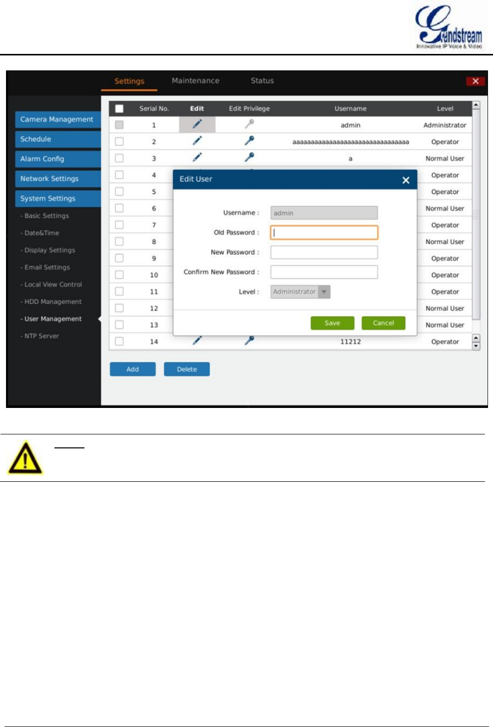
GVR3550/GVR3552 User Manual Page 85 of 125
Figure 65 System Settings Page—User Management
NOTE:
Ø Only administrator user has the authority to access user management.
ADDING A USER
Click "Add" to bring up the page as shown in figure 66. Input username, password and select level as
operator or normal user.
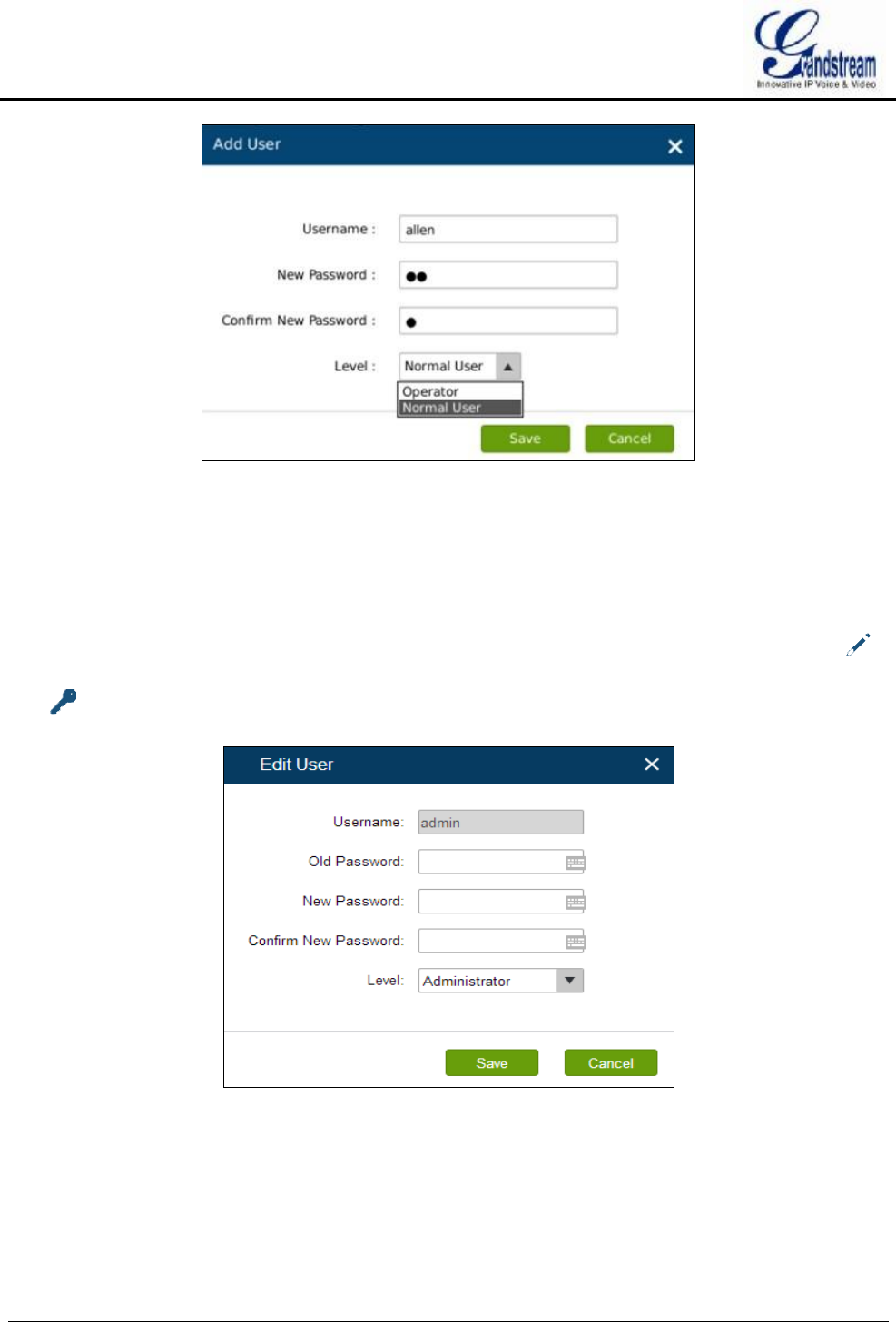
GVR3550/GVR3552 User Manual Page 86 of 125
Figure 66 User Management—Add User
Click on the "Save" button to save.
INPUT USER INFO AND EDITING AUTHORITY
The new user authority is default, users could modify the user information and authority by clicking on
and . See figure 67. Users could modify new password and user level.
Figure 67 User Management—Edit User
The normal user only has camera privilege like playback and remote preview. Check to set. See figure 68.
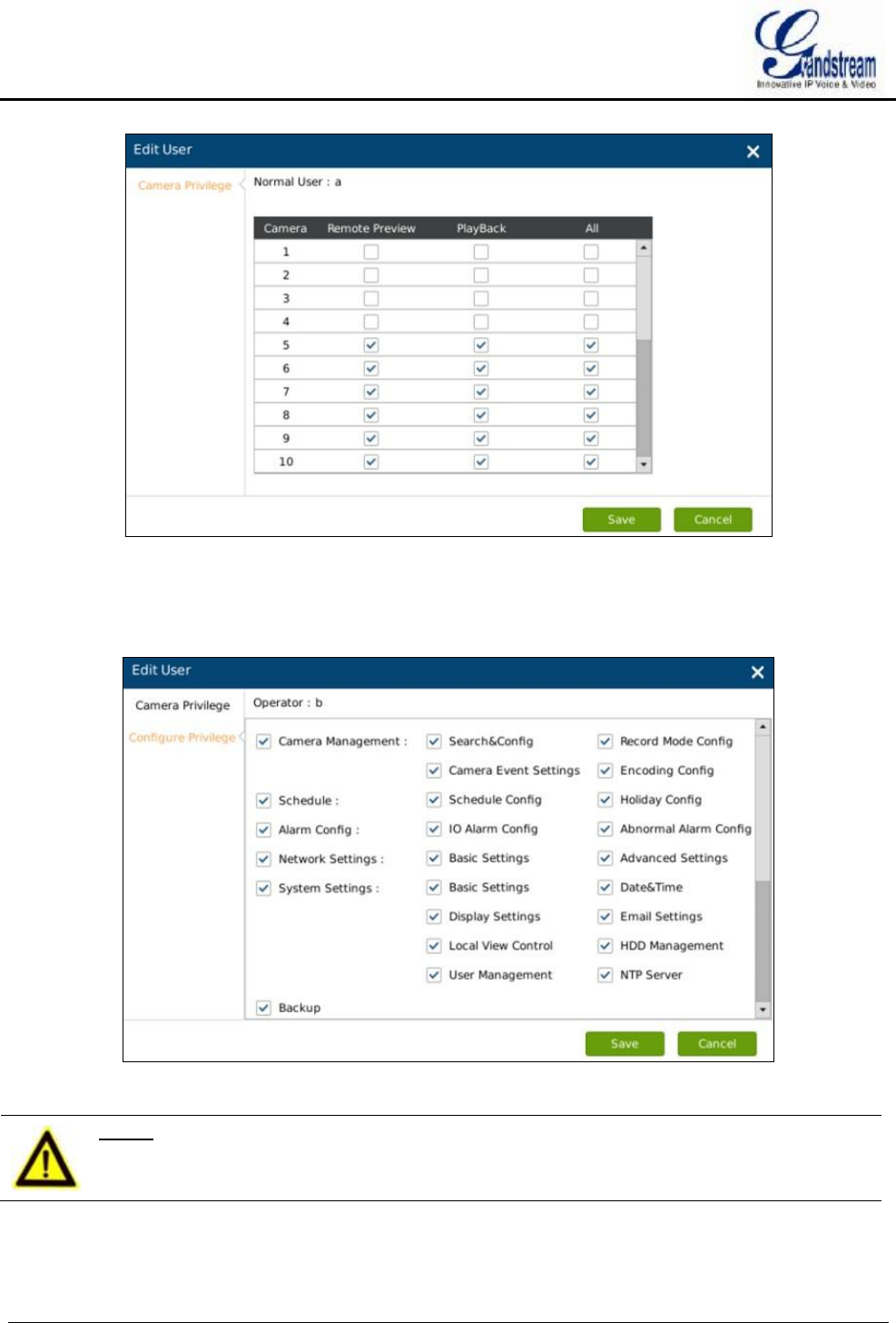
GVR3550/GVR3552 User Manual Page 87 of 125
Figure 68 User Management—Edit Normal User
Besides camera privilege, the operator user also has configure privilege. Check to set. See figure 69.
Figure 69 User Management—Edit Operator User
NOTE: Ø All users have the permission to access local preview by default. Local preview
has no access restrictions.
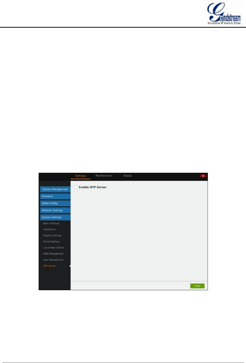
GVR3550/GVR3552 User Manual Page 88 of 125
DELETING A USER
All user accounts can be deleted except the administrator account. Check the user you want to delete then
click on the "Delete" button below the page to delete.
Privilege Specifications:
Administrator. All privilege by default.
Operator.Camera privilege and part of configure privilege except User Management, Upgrade, Reset and
Import & Export.
Normal User. Part of Camera Privilege except Manual Operation.
Camera Privilege. Remote Preview, Manual Operation, Playback.
Configure Privilege. Camera Management, Schedule, Alarm Config, Alarm Settings, Network Settings,
System Settings, etc.
NTP SERVER
GVR3550/GVR3552 could provide other devices in LAN with NTP service. Check "Enable NTP Server".
See figure 70.
Figure 70 System Settings Page—NTP Server
MAINTENANCE
Maintenance includes Upgrade, Backup, Reset & Reboot, Import & Export and Troubleshooting.

GVR3550/GVR3552 User Manual Page 89 of 125
UPGRADE
GVR3550/GVR3552 supports upgrade via TFTP / HTTP / HTTPS and Manual Upload.
Table 34 Upgrade Parameters Explanation
Parameter Explanation
Upgrade Via Firmware upgrade via TFTP / HTTP / HTTPS or Manual Upload. The default
setting is "HTTP".
Firmware Server
Path
IP address or domain name when upgrade server, only available when the
upgrade mode is TFTP / HTTP / HTTPS.
Firmware File Path Upgrade local firmware file to upgrade device.
Firmware File Prefix Enables your ITSP to lock firmware updates. If configured, only the firmware with
the matching encrypted prefix will be downloaded and flashed into the device.
Firmware File Postfix
Enables your ITSP to lock firmware updates. If configured, only the firmware with
the matching encrypted postfix will be downloaded and flashed the device.
DHCP Option 66
Override Server
The default is "No". If check "Yes", the device will obtain IP address and firmware
upgrade server address via DHCP (configured via DHCP).The address will
override the path the "Firmware Server Path" specifies to fulfill auto deployment.
The upgrade will use force TFTP.
BACKUP
GVR3550/GVR3552 supports quick backup record and search backup record. Users could choose the
camera and set the record time for quick backup, or search file for backup via record type, file type or record
time. See figure 71.
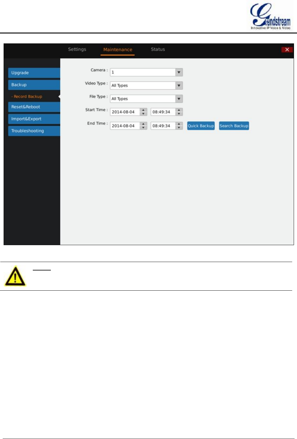
GVR3550/GVR3552 User Manual Page 90 of 125
Figure 71 Backup Page—Record Backup
NOTE:
Ø Quick backup video and search backup video only support local.
QUICK BACKUP
1. Select camera and input record type, file type, start time and end time, click on the "Quick Backup"
button.
2. Access the Backup page as shown in figure 72. Click on the "Refresh" button to refresh the device name
that saves the file.
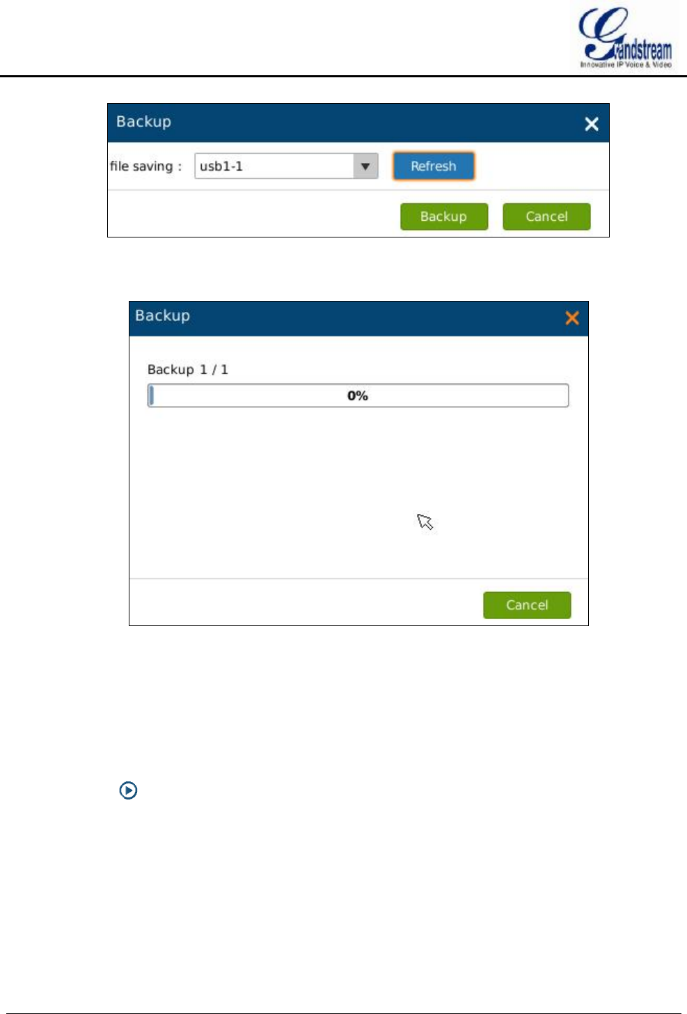
GVR3550/GVR3552 User Manual Page 91 of 125
Figure 72 Backup Page—Quick Backup Page
3. Click on the "Backup" button to export all files.
Figure 73 Backup Page—Quick Backup Progress Bar
SEARCH BACKUP
1. Select camera and set record type, file type, record time.
2. Click on the "Search Backup" button to enter the corresponding page as shown in figure 74. Users could
also click on to playback record.
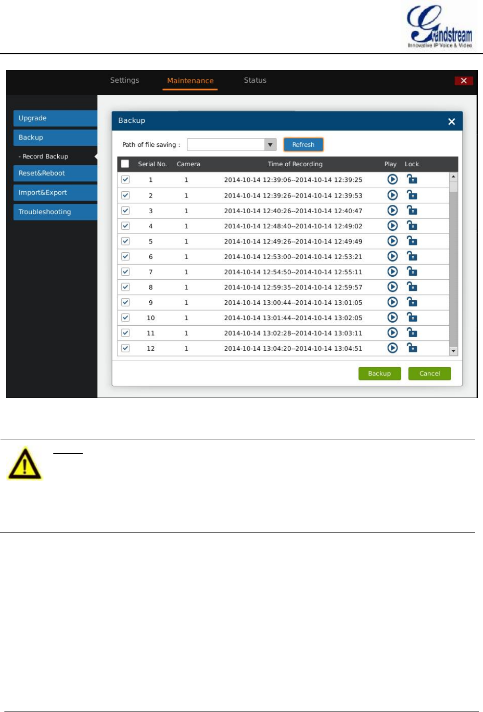
GVR3550/GVR3552 User Manual Page 92 of 125
Figure 74 Backup Page—Search Backup
3. Check the video and click on the "Backup" button to enter the backup page to export all files.
NOTE:
Ø Please click on the "Refresh" button if the USB device cannot be detected after
inserting. If the refresh is invalid, please unplug the USB then insert again. If
still failed, the reason might be the USB is not incompatible with GVR3550.
Please try another USB device instead.
Ø If the file format of USB device is incorrect, format USB then try again.
GVR3550 supports FAT32 or NTFS format USB storage devices..
RESET & REBOOT
Click on the "Reboot" button to boot up. To reset factory settings, users could select "Clear All Data" or
"Retain Network Data Only" then click on "Reset" button. Restore factory settings will not affect HDD
storage.
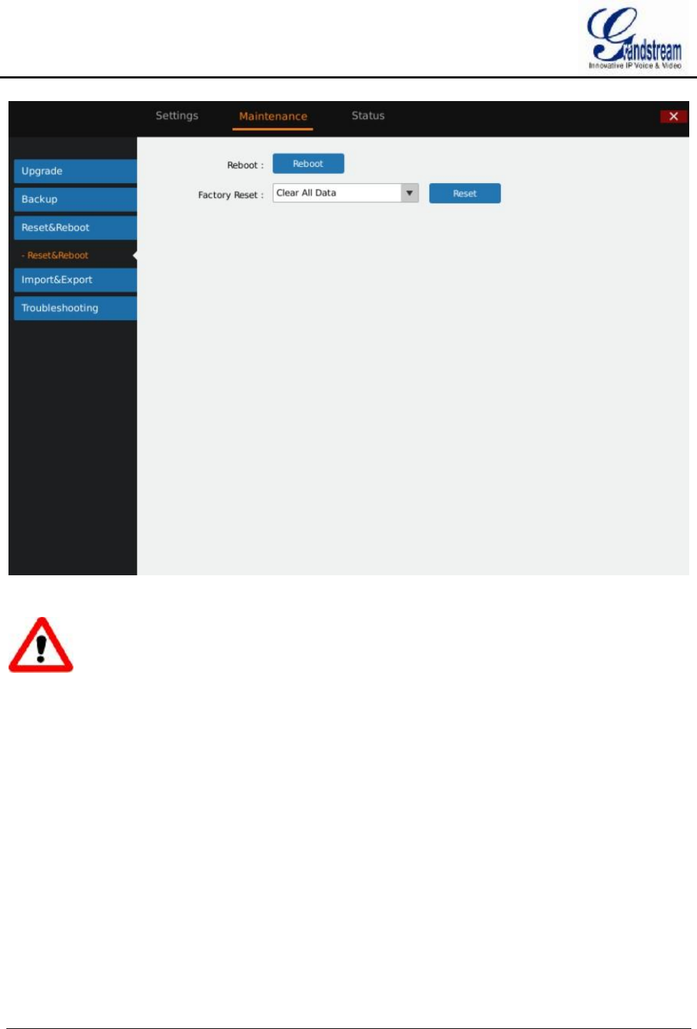
GVR3550/GVR3552 User Manual Page 93 of 125
Figure 75 Reset & Reboot Page
Warning!
Ø GVR3550 data will be erased and set to factory default if enable Factory Reset, please take caution to
use this function.
IMPORT & EXPORT
GVR3550/GVR3552 supports import/export configuration file. Users could import GVR3550/GVR3552
configuration file to external storage device for backup, or import the file to the GVR3550/GVR3552 thus to
reduce manual settings procedures. Users could apply configuration backup function if need to configure the
same parameters on multiple devices. The Import/Export page is shown in figure 76.
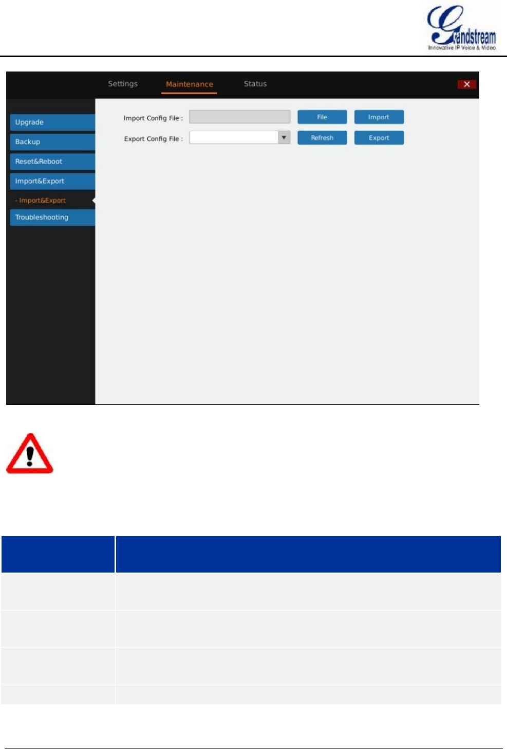
GVR3550/GVR3552 User Manual Page 94 of 125
Figure 76 Import & Export Page
Warning!
Ø Restart GVR3550/GVR3552 to make changes take effect after importing configuration file. The original
file would be overwritten by the new one, please use this function with caution.
Table 35 Import & Export Parameters Explanation
Parameter Explanation
Import Configuration
File
Select the configuration file.
Import Click to bring up the warning page, confirm whether to reboot GVR to make
changes take effect.
Export Configuration
File
Browse to select the path to export configuration file.
Export Click to export the configuration file to external storage device.
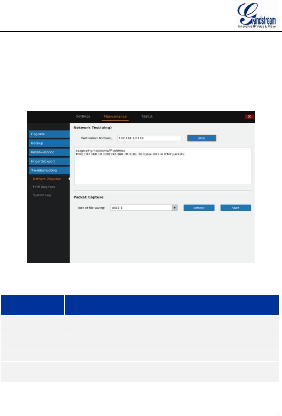
GVR3550/GVR3552 User Manual Page 95 of 125
TROUBLESHOOTING
Troubleshooting includes Network Diagnosis, System Log and Debug Log.
NETWORK DIAGNOSIS
Network diagnosis includes network test and packet capture. See figure 77 below.
Figure 77 Network Diagnosis Page
Table 36 Network Diagnose Parameters Explanation
Parameter Explanation
Network Test (Ping) Input the destination address, click on "Start" to initiate test, click "Stop" to end test.
Diagnose Output Display the diagnosis result of GVR3550 and the destination IP address.
Path of File Saving Display external device, users could choose one if there are multiple choices.
Refresh Display the new external device.
Start/End Click to start capture. The capture file will be saved in the root directory of selected
external device. Click "Stop" to end capture.
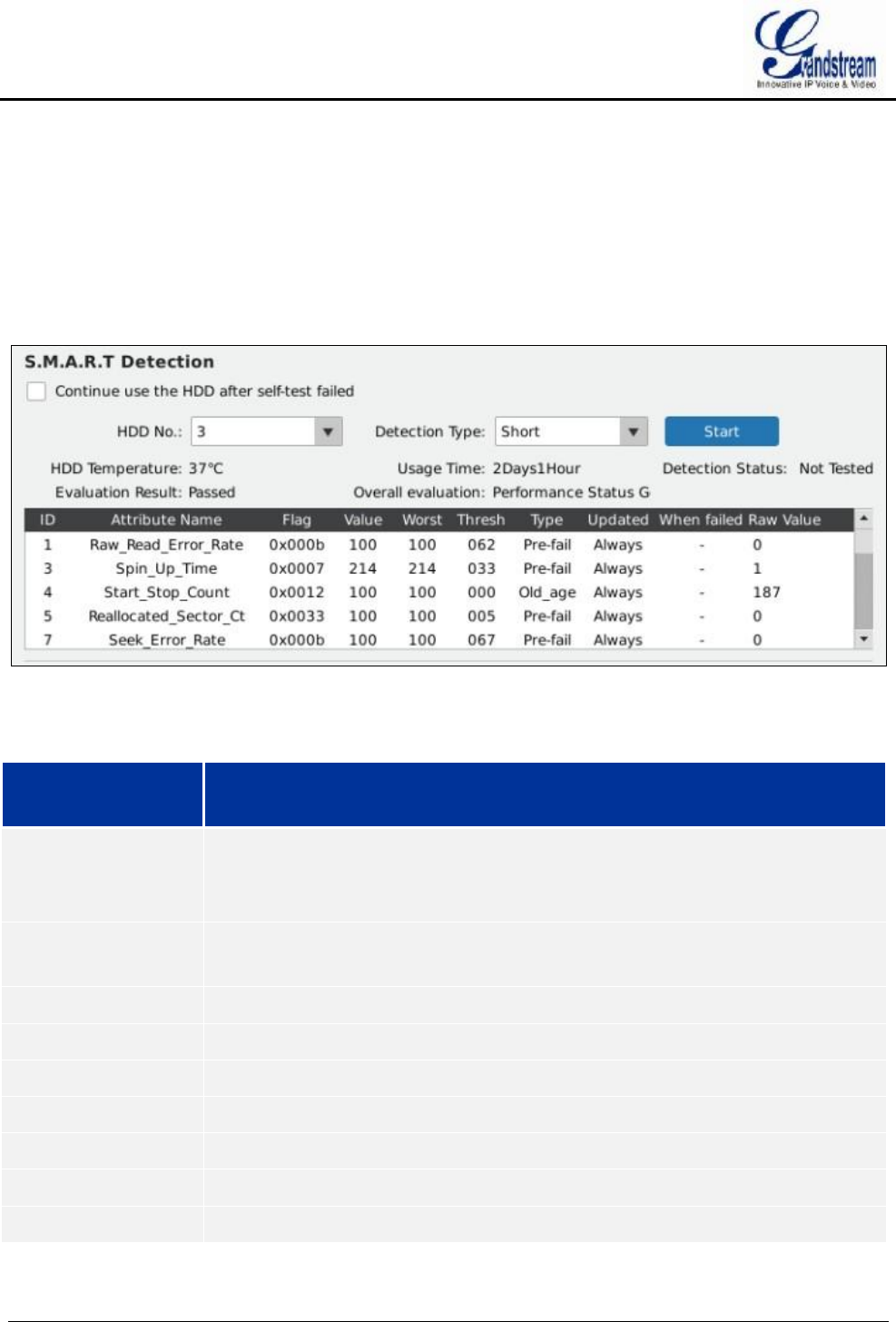
GVR3550/GVR3552 User Manual Page 96 of 125
HDD DETECTION
GVR3550/GVR3552 provides S.M.A.R.T. (Self-Monitoring, Analysis and Reporting Technology) detection
and bad sector detection. Users could view HDD running status via HDD detection.
S.M.A.R.T detection provides detection like HDD heads, temperature, material of disk surface and
forecasting the underlying problems of HDD that may occur in time.
S.M.A.R.T detection page is as shown in Figure 78 below.
Figure 78 S.M.A.R.T. Detection Page
Table 37 HDD S.M.A.R.T Detection Parameters Explanation
Parameter Explanation
Continue Use the
HDD after Self-test
Failed
Continue to use the HDD if self-test failed in the process of S.M.A.R.T. Detection.
Note: Once enabled, it may cause HDD error, please be careful!
HDD No. HDD Number 1-4 will be allocated in sequence after HDD installation, the number
will not be changed in the subsequent use.
Detection Type Set S.M.A.R.T. detection type: Short, Long, Conveyance.
Start Click the button to start S.M.A.R.T. detection.
HDD Temperature Display HDD temperature S.M.A.R.T detection detected.
Usage Time Display total HDD usage time S.M.A.R.T detection detected.
Detection Status S.M.A.R.T detection results.
Evaluation Result S.M.A.R.T detection results on HDD status.
Overall Evaluation Display overall HDD status after detection.
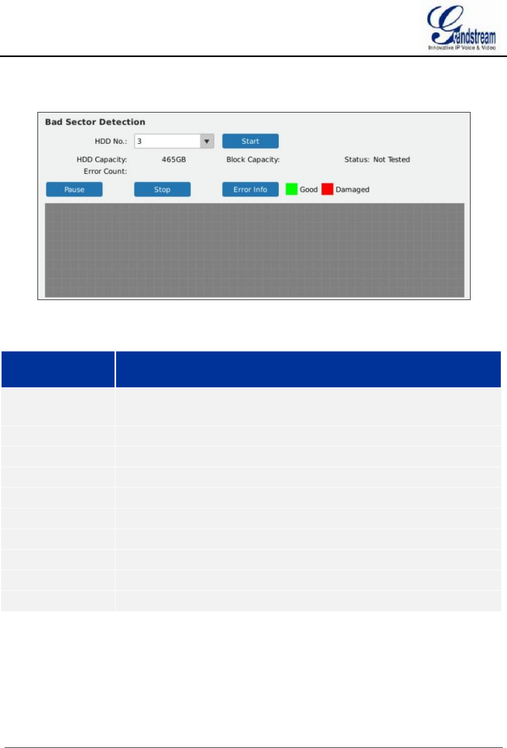
GVR3550/GVR3552 User Manual Page 97 of 125
The HDD bad sector could be detected via bad sector detection as shown in figure 79.
Figure 79 HDD Bad Sector Detection Page
Table 38 HDD Bad Sector Detection Parameters Explanation
Parameter Explanation
HDD No. HDD Number 1-4 will be allocated in sequence after HDD installation, the number
will not be changed in the subsequent use.
Start Click the button to start bad sector detection.
HDD Capacity Display total HDD capacity.
Block Capacity Display HDD block capacity.
Status Display bad sector detection status: Testing, Test Paused or Not Tested.
Error Count Display how many HDD errors exist in.
Pause/Continue Pause/Continue bad sector detection.
Stop Stop bad sector detection.
Error Info Display error details after detection.
HDD Status Display Tag HDD status with various colors: Good, Damaged.
SYSTEM LOG
Users could view GVR3550/GVR3552 running status. See figure 80.
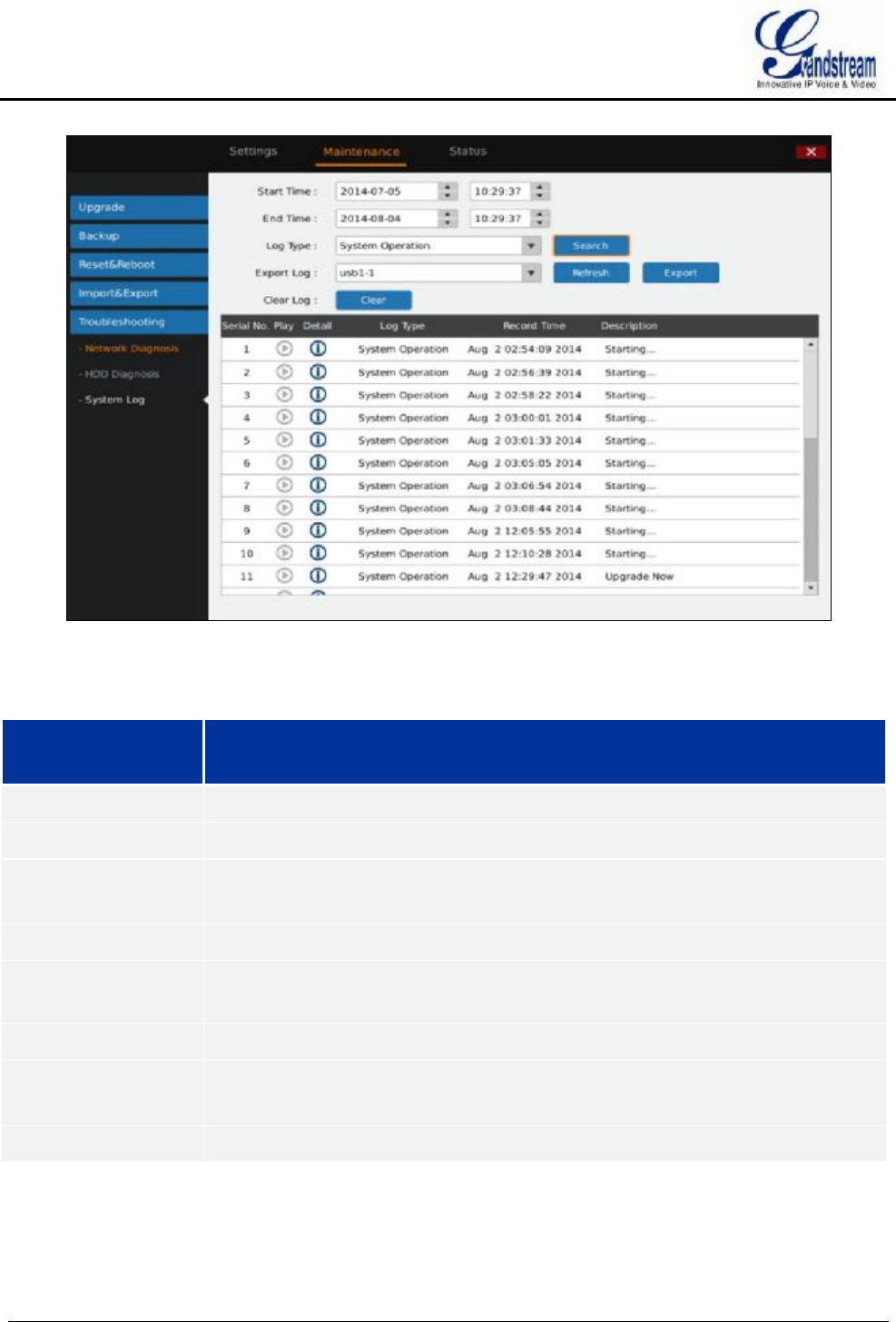
GVR3550/GVR3552 User Manual Page 98 of 125
Figure 80 System Log Page
Table 39 System Log Parameters Explanation
Parameter Explanation
Start Time Search log start time.
End Time Search log end time.
Log Type All Types, System Operation, Configure Operation, Data Management, Alarm
Event, Recording Operation, User Management, Clear Log and File Operation.
Search Click to search log and display it in the log list.
Export Log Export the log and save it to the target path.
Clear Log Click "Clear" to clear syslog.
Playback When the syslog type is alarm event, the playback button is blue. Click the button
to playback the video.
Details Click to view the log details.
STATUS
Status includes Recording Info, System Info, Network Info, Resource Usage, Alarm Info and HDD Info.
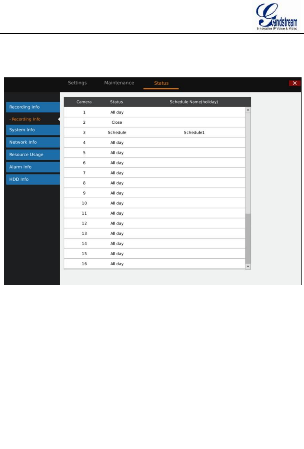
GVR3550/GVR3552 User Manual Page 99 of 125
RECORDING INFO
User could view the connected camera status and the schedule record on GVR3550/GVR3552. See figure 81.
Figure 81 Recording Info Page
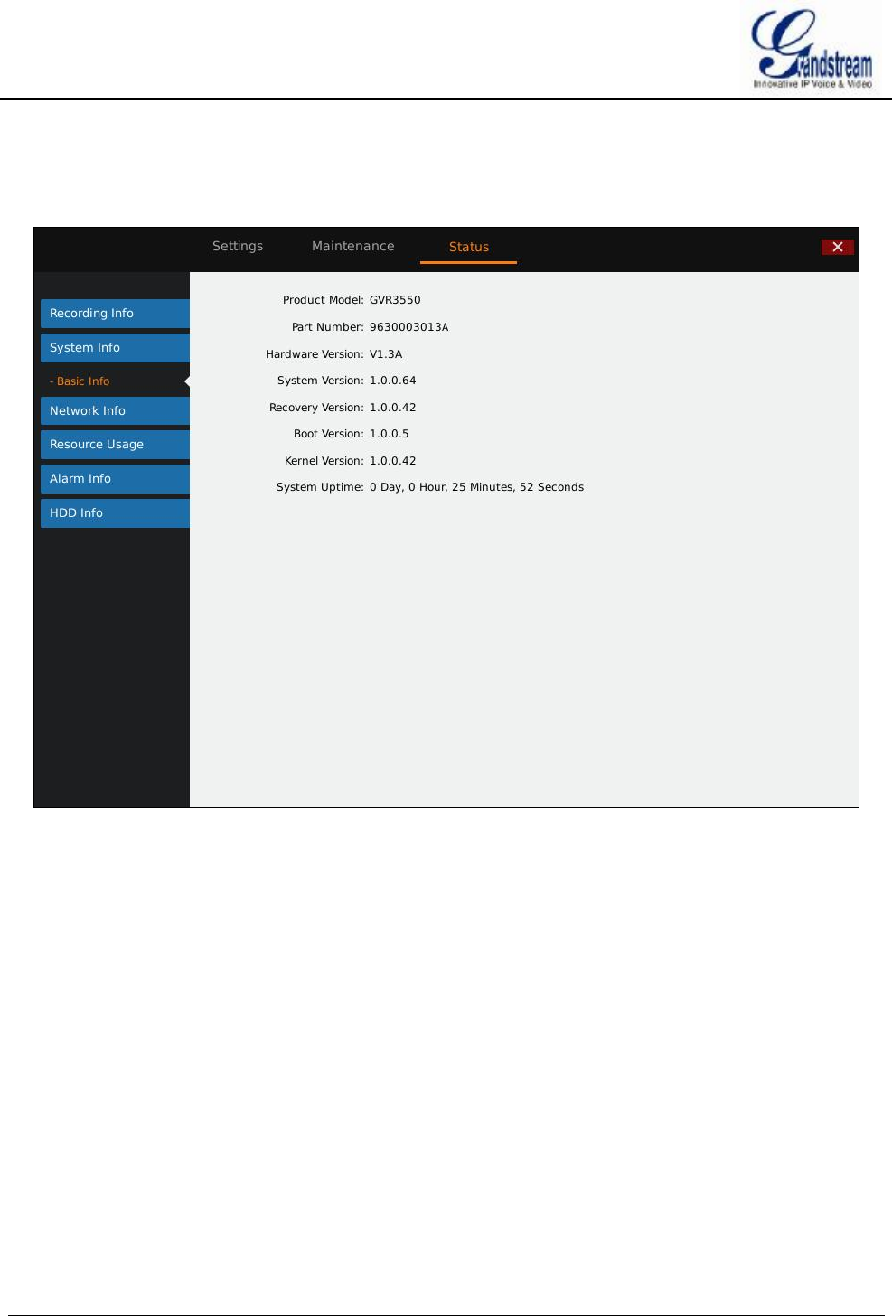
GVR3550/GVR3552 User Manual Page 100 of 125
SYSTEM INFO
Users could view GVR3550/GVR3552 part number and hardware version as shown in Figure 82.
Figure 82 System Info Page
NETWORK INFO
Users could view address type, IP address, and LAN data Sending & Receiving status. As shown in figure
83.
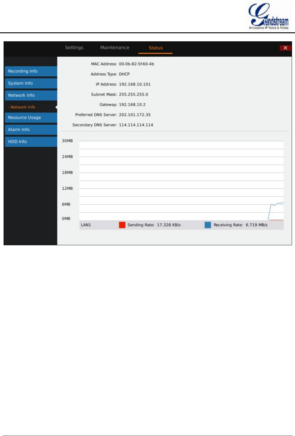
GVR3550/GVR3552 User Manual Page 101 of 125
Figure 83 Network Info Page
RESOURCE USAGE
Users can view CPU usage and memory usage as shown in figure 84.
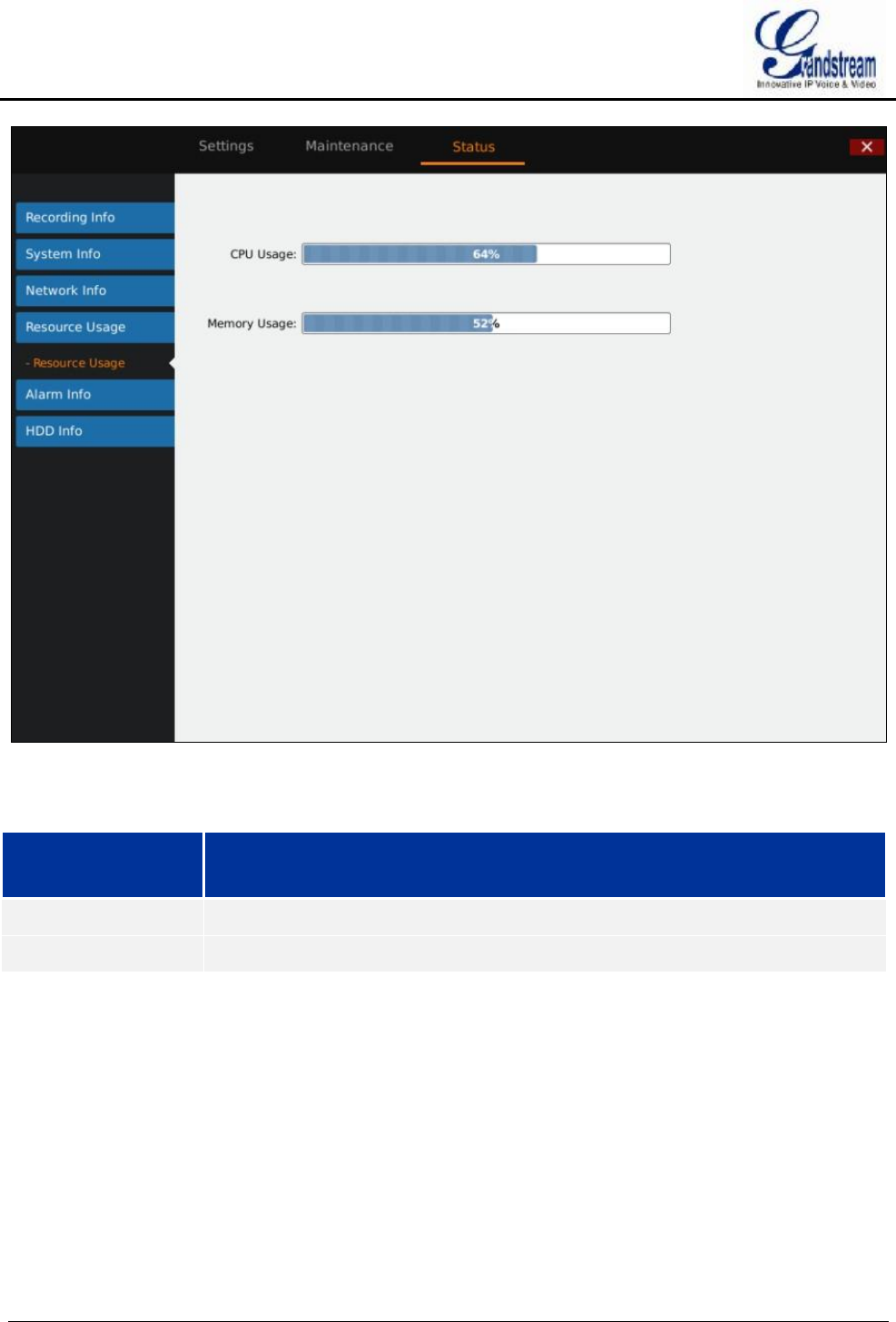
GVR3550/GVR3552 User Manual Page 102 of 125
Figure 84 Resource Usage Page
Table 40 Device Status Parameters Explanation
Parameter Explanation
CPU Usage Real-time display GVR3550 CPU usage status.
Memory Usage Real-time display GVR3550 memory usage status.
ALARM INFO
Users can view alarm types of cameras. As shown in figure 85.
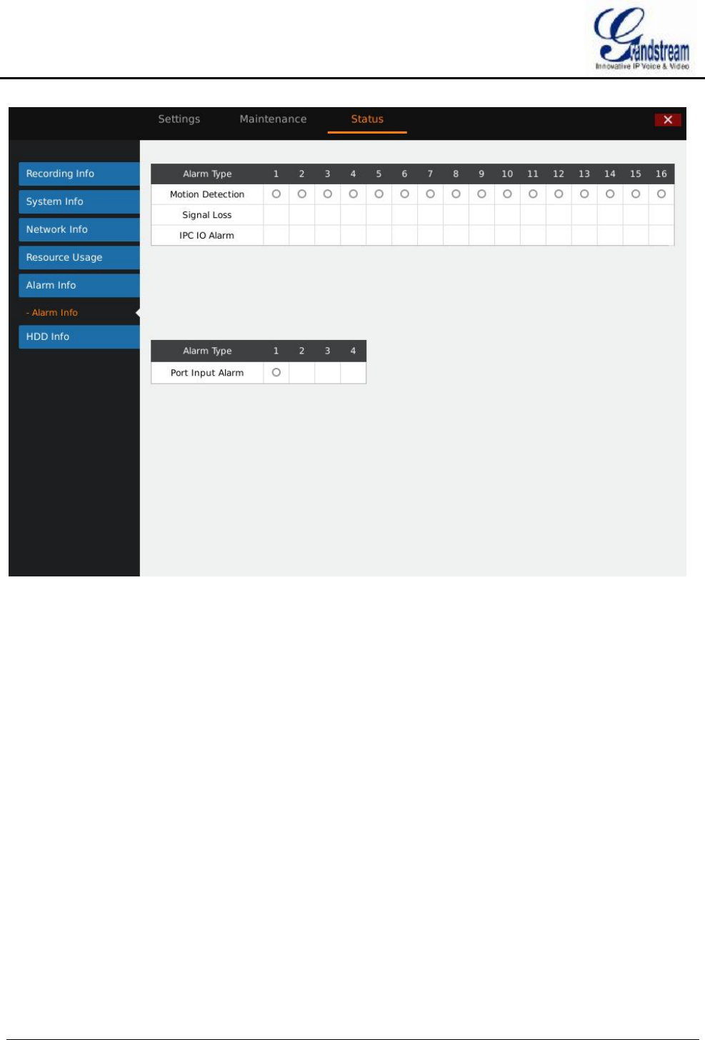
GVR3550/GVR3552 User Manual Page 103 of 125
Figure 85 Alarm Info Page
HDD INFO
Users can view HDD No., attribution volume, serial No., total space and HDD status. As shown in figure 86.
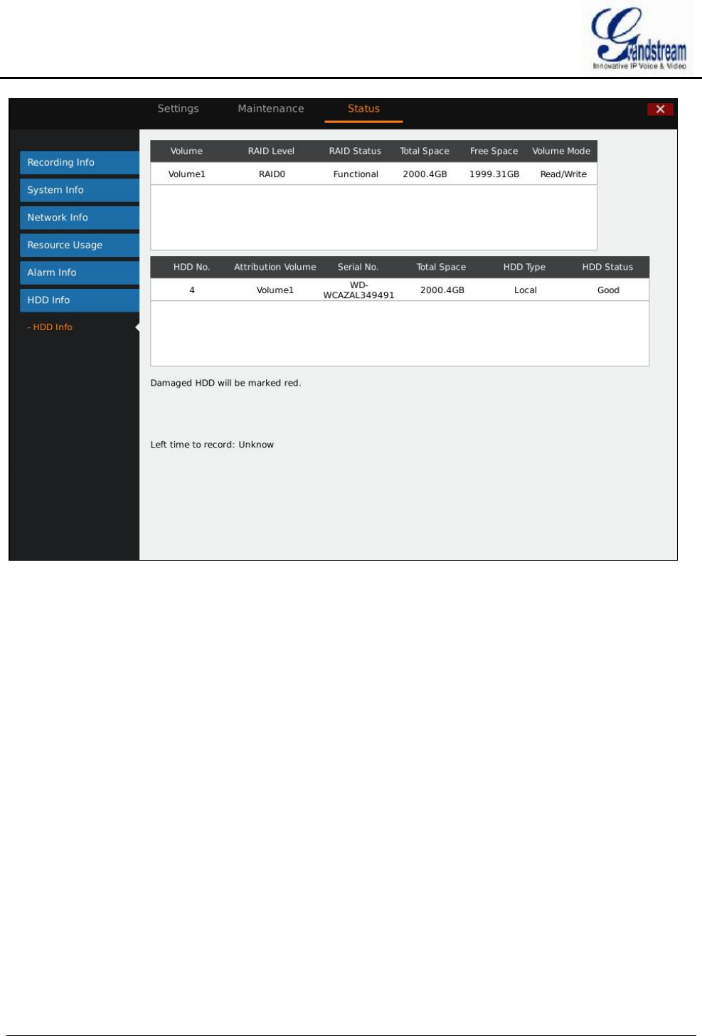
GVR3550/GVR3552 User Manual Page 104 of 125
Figure 86 HDD Info Page
LOGOUT
GVR3550 would display preview screen after logout, please input username and password to login for
authentication when entering the menu again.

GVR3550/GVR3552 User Manual Page 105 of 125
WEB MANAGEMENT
OVERVIEW
GVR3550/GVR3552 supports accessing and managing GVR on Web page via the remote PC. The Web page
provides operations like video playback & search, video settings, alarm settings, system settings, PTZ
control, etc. Most operations are the same as on local GUI.
NOTE: Ø The following chapters are only to specify the operations differ from local GUI.
Please refer to local GUI chapters for other operations.
SYSTEM LOGIN
This chapter introduces how to login the GVR3550/GVR3552 Web page via Web browser like Microsoft’s
IE, Mozilla Firefox and Google Chrome.
1. Access a network;
2. Go to Main Menu->Status->Network Info to find the GVR IP address when it runs normally;
3. Open a web browser and enter the GVR3550/GVR3552 IP address in the address bar, e.g.:
http://192.168.10.101. (The default port No. is 80);
4. Press the "Enter" button to enter GVR3550/GVR3552 Web Login page, input username and password in
the prompt box. The default administrator username and password are: admin, admin. Please modify the
password after login without delay;
5. Set language to English or Chinese in the drop-down menu;
6. Click the "Login" button to enter the Web page.
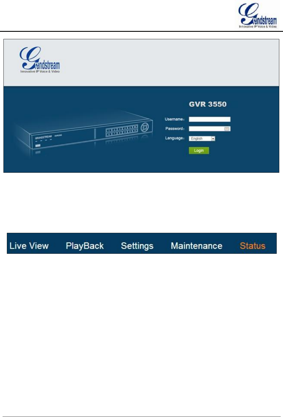
GVR3550/GVR3552 User Manual Page 106 of 125
Figure 87 Web Page—Login
WEB PAGE INTRODUCTION
Users can switch among live View, Playback, Settings, Maintenance and Status. You can also switch
language on this page or exit.
Figure 88 Web Page—Menu
LIVE VIEW
Users need to download and install the video playback plug-in "GVRView.exe" first before preview. Close
browser before installation to avid failure. Follow the step below:
1. Open a web browser and enter the GVR3550 IP address in the address bar to login the Web page;
2. Click on the plug-in installation remind link to download plug-in to PC;
3. Close browser, install plug-in and start it.
4. Open browser again and login the Web page to check whether the live view window could display. If
the prompt is the plug-in is not installed, please check whether the browser prohibits plug-in running, if
prohibits, please manual set to allow the plug-in running and refresh the browser.
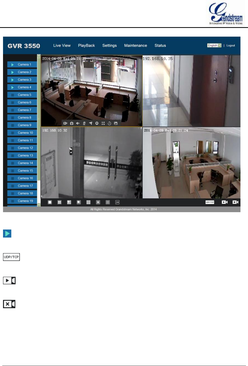
GVR3550/GVR3552 User Manual Page 107 of 125
Figure 89 Web Live View Page
Open camera. Select one window on screen with mouse and double click the camera name to display
the preview screen,
TCP/UDP Switch. Click on the button to set all existing camera transmission protocol to TCP or
UDP.
Open All Preview. Click on the button to open preview screen of all cameras. Remote preview
supports up to 24 cameras.
Close All Preview.Click on the button to close preview screen of all cameras.
Preview Window Split. Split screen to multiple windows like 1 window, 4 windows, 9 windows, 16
windows, 24 windows.
Double click on one window when preview to view camera settings menu if has enough space. See table
below.
Table 41 Remote Preview Operation Explanation
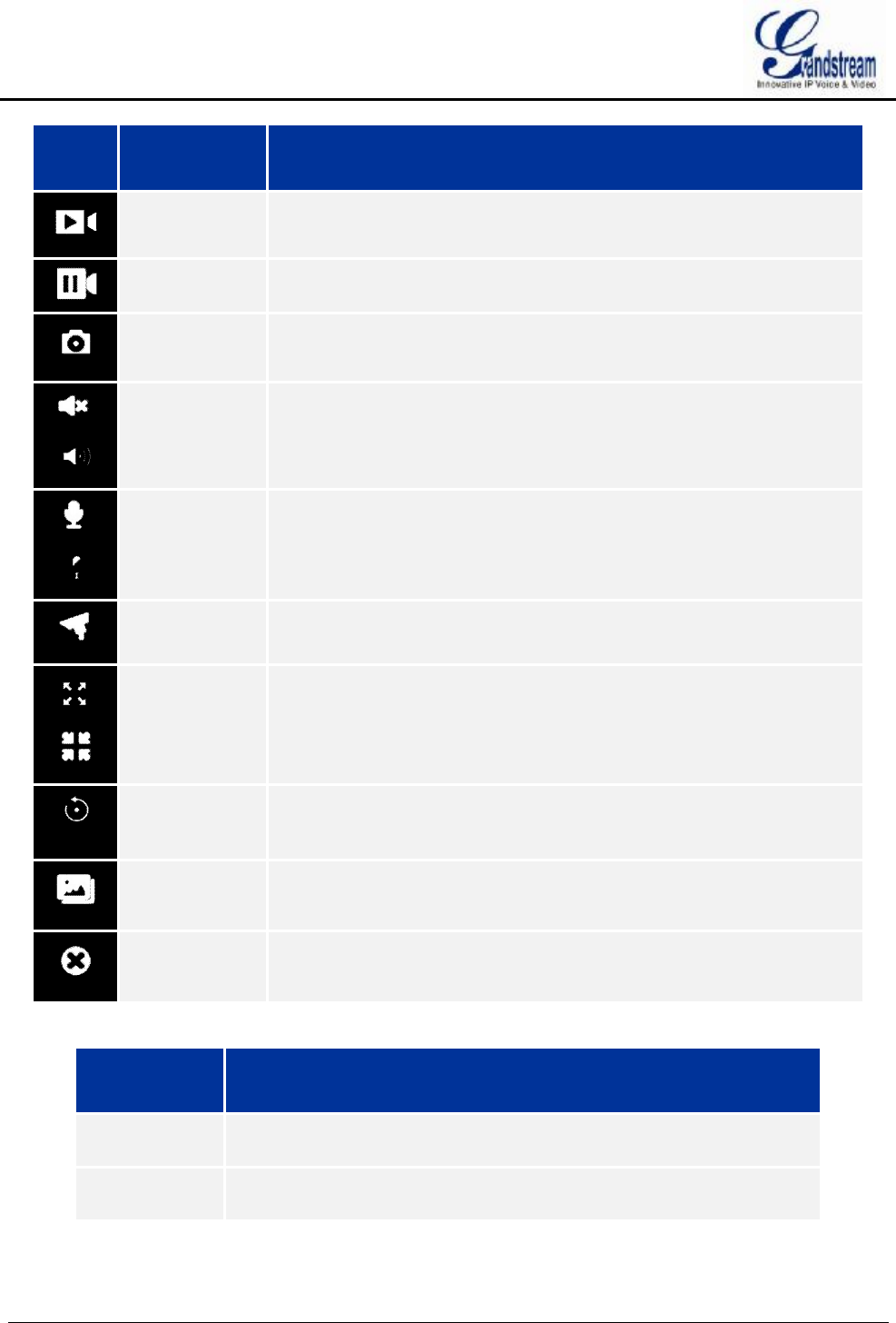
GVR3550/GVR3552 User Manual Page 108 of 125
Icon Name Explanation
Closed Record
The camera is not recording now.
Manual
Record
The camera is in manual record mode. The default path:
C:\GVR_Record
Capture Capture preview screen. Users could save the snapshots under
C:\GVR_Capture directory on PC.
Mute/Unmute When the volume in on, if the remote camera is installed with audio input
device, users could listen in to the remote party.
Start/Stop
Intercom
When the intercom is on, if the remote camera is installed with audio
output device, users could speak to the remote camera via local audio
input device.
PTZ Control Click to enable PTZ control to configure PTZ preset, patrol and pattern.
Switch to Full
Screen
Switch the current screen to full screen or double click to enter full
screen mode, double click again to exit full screen.
Instant
Playback
Playback video in preset time. It will prompt "The selected camera has
no video "if has no existing video. Users could set the preset time in
Basic System Settings chapter.
Image Config Enter the corresponding page to adjust the current window image.
Close Preview
Close preview window.
Table 42 Remote Preview Camera Specifications
Name Explanation
Camera
Stream
Click right mouse to enter the stream settings page to set primary
stream or secondary stream.
Recording
Status
Display the current camera recording status (being recorded or not).
The video file is saved on PC.
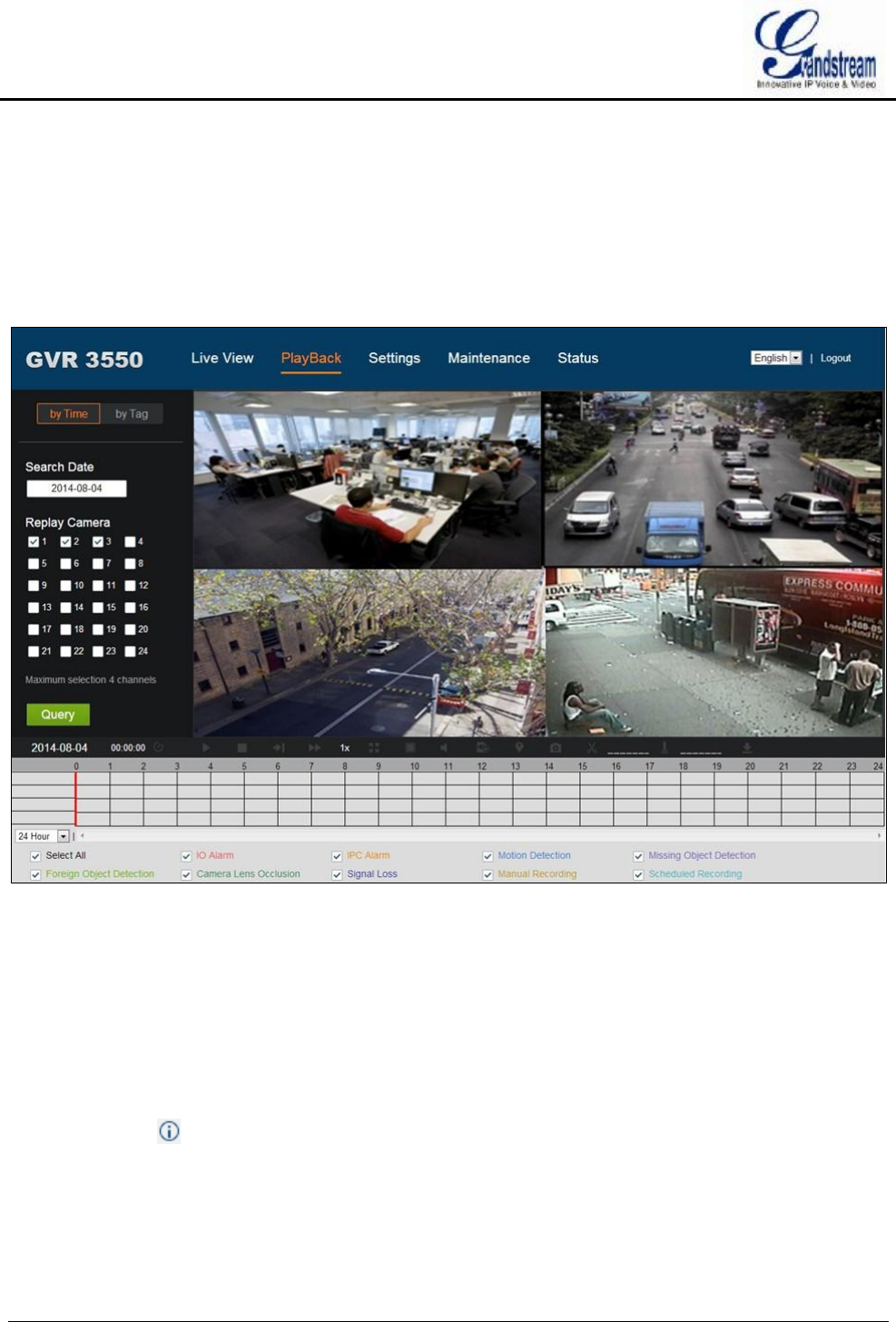
GVR3550/GVR3552 User Manual Page 109 of 125
PLAYBACK
Please refer to the chapter Local Playback to view remote playback on Web page. It should be noted that the
video which could be searched on the Web page is the one stored in GVR3550/GVR3552 HDD, snapshots
and clips could only be saved on PC but not on local GUI. The playback on the Web page is as shown in
figure 90.
Figure 90 Web Playback Page
SETTINGS
Please refer to chapter Main Menu to set settings on the Web page. It should be noted that the path to save
snapshots and clips are only for the Web page, the related files are saved on PC and users could not make
operations on Local GUI.
Put the cursor on to view the parameters.
BASIC SYSTEM SETTINGS
The Basic System Settings on Web page is as shown below; please refer to chapter Basic System Settings to
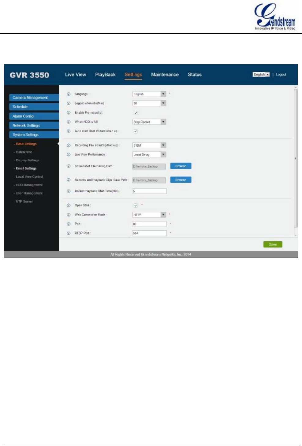
GVR3550/GVR3552 User Manual Page 110 of 125
view other parameters settings. Screenshot file saving path, Videos and Playback Clips Path can only be set
to local path in PC.
Figure 91 Web Page—Basic Settings
DEBUG LOG
The Maintenance on the Web page is shown in figure 90. Please refer to chapter Maintenance to view other
parameters settings.
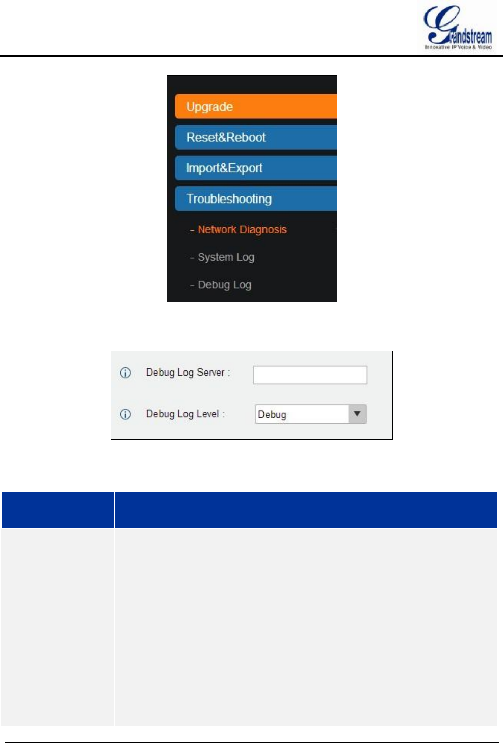
GVR3550/GVR3552 User Manual Page 111 of 125
Figure 92 Web Page—Maintenance Menu
Go to Maintenance->Troubleshooting-> Debug Log to set debug parameters.
Figure 93 Web Page—Debug Log
Table 43 Debug Log Parameters Explanation
Parameter Explanation
Debug Log Server The IP address or URL of the debug log server.
Debug Log Level Selects the log level. The default setting "None" means sending no log. The log
priority from high to low is Debug, Info, Warning and Error.
Debug Log based on the following events:
The product model/version (INFO level)
NAT Info (INFO level)
Registration state changes (INFO level)
Negotiation coding (INFO level)
Ethernet connection (INFO level)
SLIC debris abnormal (WARNING and ERROR level)
Abnormal memory (ERROR level)

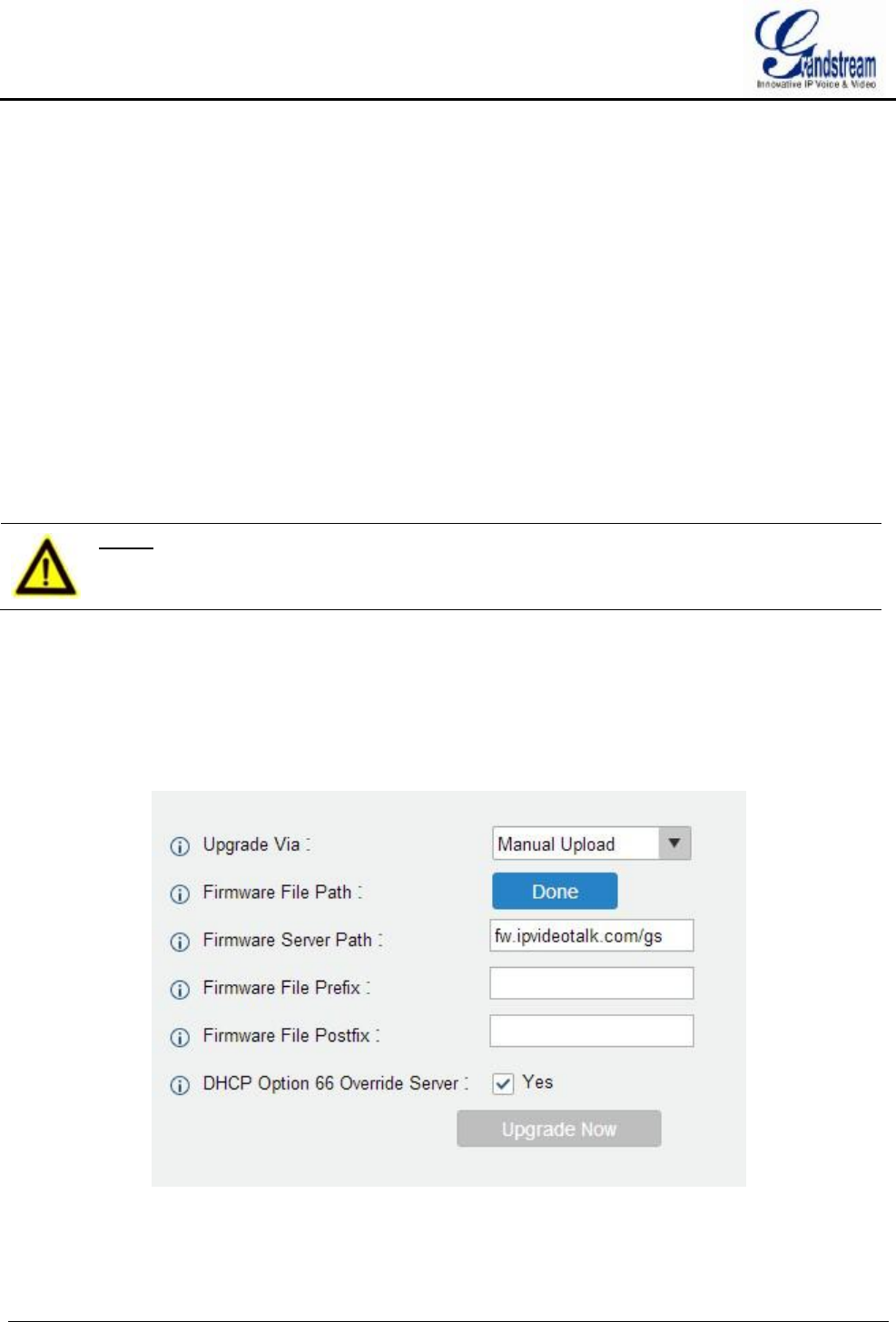
GVR3550/GVR3552 User Manual Page 113 of 125
FIRMWARE UPDATE
GVR3550/GVR3552 supports software upgrade via TFTP /HTTP/HTTPS server. Please go to Maintenance
->Upgrade to configure.
GVR3550/GVR3552 supports the following upgrade modes:
· Manual upload firmware file to upgrade
· Upgrade via TFTP firmware server
· Upgrade via HTTP/HTTPS firmware server
NOTE: Ø It is HIGHLY recommended that use an Uninterruptible Power Supply (UPS) or
it might be fail if emergency cutoff occurs in the process of update.
Ø Please unpack the compression package before upgrade when manual update.
MANUAL UPGRADE
1. Go to Maintenance ->Upgrade to set upgrade mode to "Manual Upload";
2. Click on the "File" button in the "Firmware File Path" entry to select the firmware file;
3. Click on "Upgrade Now" button to upload firmware, the screen is shown below;
Figure 94 Manual Upgrade Page
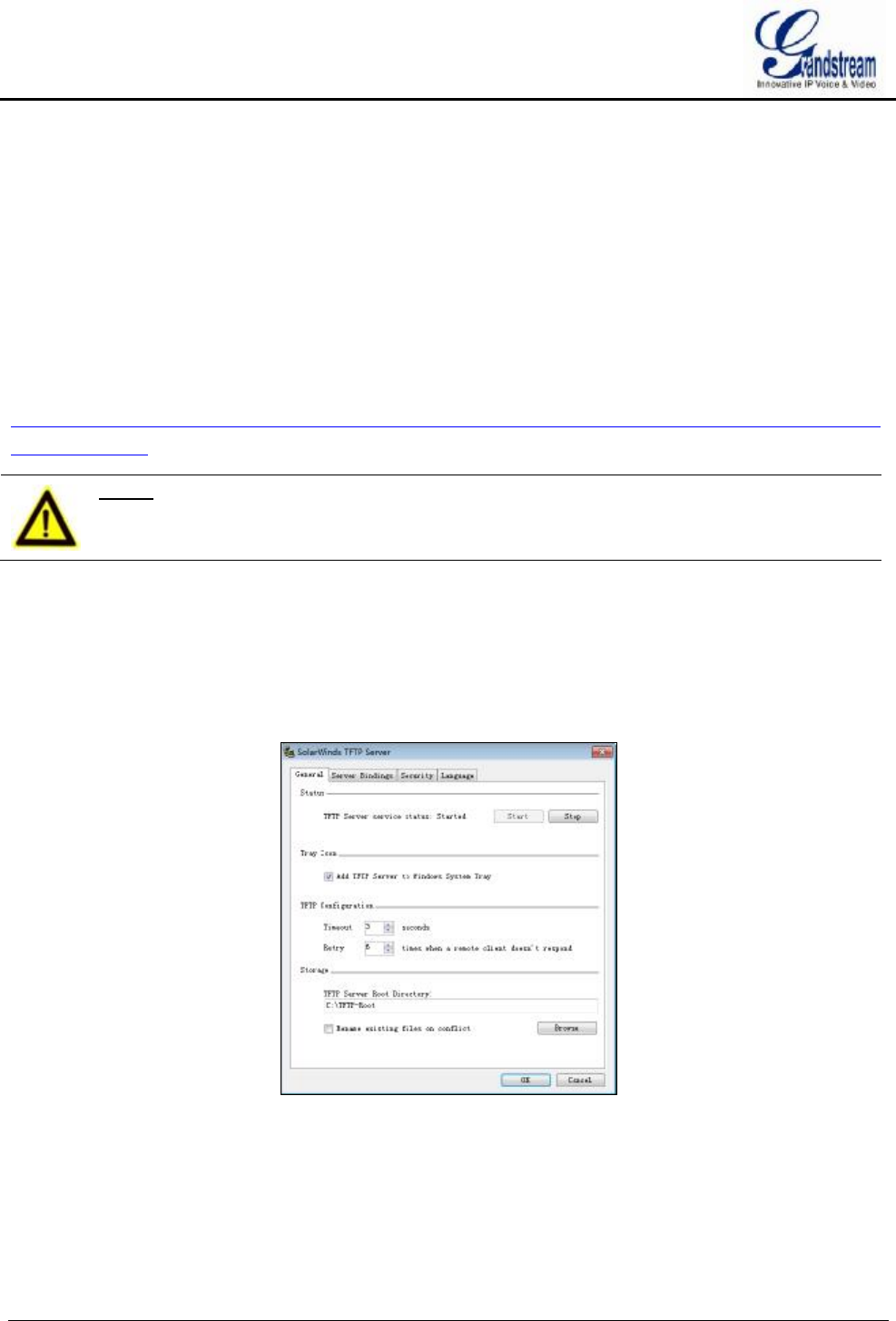
GVR3550/GVR3552 User Manual Page 114 of 125
4. GVR3550/GVR3552 will start upgrade automatically once uploaded the file, it will prompt users
whether to reboot when complete upgrade. With no operations in 30 seconds the GVR3550/GVR3552
will reboot automatically.
UPGRADE VIA TFTP FIRMWARE SERVER
For GVR3550, please configure TFTP server and put the file "gvr3550fw.bin" under TFTP server directory.
The file for GVR3552 is "gvr3552fw.bin".
Users could also download the free TFTP server by visiting the link below to download free Windows TFTP
server:
http://www.solarwinds.com/register/?program=52&c=70150000000CcH2&INTCMP=DLIndexA_FreeTools
_freeTFTPserver
NOTE: Ø The default firmware file for GVR3550 should be named "gvr3550fw.bin" while
the file for GVR3552 is "gvr3552fw.bin", other names may cause upgrade
failure.
CONFIGURING TFTP SERVER
In this chapter, we take SolarWinds TFTP server as an example.
1. Open TFTP server;
2. Click "File" in the upper left corner and choose "Configure";
Figure 95 Configure Dialog
3. Set the directory to save the file in "Storage" entry under "General" tab, as shown in figure 96;
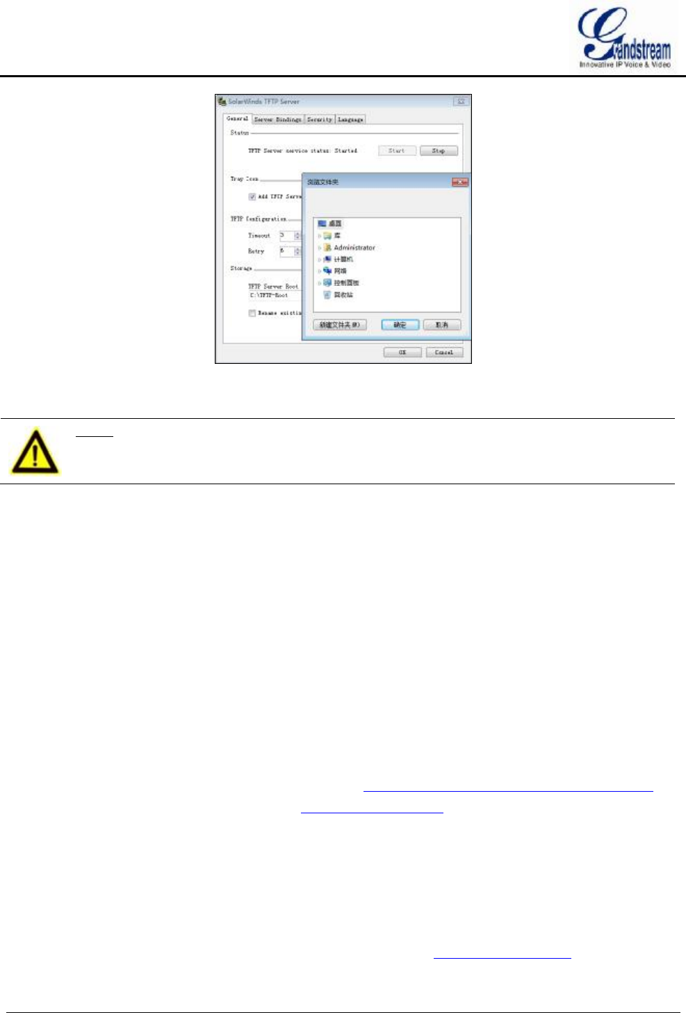
GVR3550/GVR3552 User Manual Page 115 of 125
Figure 96 TFTP Server Directory Settings
4. Select directory and click "OK".
NOTE:
Ø The file uploaded to the server directory should be the .bin file after unzip.
UPGRADE FIRMWARE WITH TFTP SERVER
1. Unzip the firmware file, set the folder to save the firmware file to root directory of TFTP server;
2. Connect the PC and the GVR to the same LAN;
3. Open TFTP server and go to file menu->Configure->Security and set to "Transmission Only";
4. Open TFTP server, go to Settings->Advanced Settings to select TFTP;
5. Set the firmware server path to the PC IP address, which is the IP address of the TFTP server;
6. Click "Upgrade Now" and the device would restart automatically after the upgrade completed.
UPGRADE VIA HTTP/HTTPS FIRMWARE SERVER
Users could use Grandsteam HTTP server that supports NAT. Connect to server to upgrade firmware.
Download the free Grandsteam server by visiting the link http://www.grandstream.com/support/firmware
You can also download free HTTP server from http://httpd.apache.org/ or use Microsoft IIS server.
CONFIGURING HTTP SERVER
In this chapter, we take using Apache HTTP Server2.2 server in windows XP to introduce the steps to
configure HTTP server.
Users could obtain the Apache HTTP server installation software via http://httpd.apache.org, please finish the
default installation according to the wizard.

GVR3550/GVR3552 User Manual Page 116 of 125
1. Open Apache server. Go to Start ->All Programs ->Apache HTTP Server 2.2 -> Monitor Apache
Servers on a PC which has installed Apache server. The icon in the notification area of taskbar
indicates Apache server is already enabled. If displays , select "Start" to open server;
2. Put the prepared file to the following path:
Installation Path \ Apache Software Foundation \ Apache2.2 \ htdocs.
NOTE:
Ø If put the file under the folder "htdocs", the URL format to access the Apache
server is: http:// The IP address of PC that installed the Apache server .e.g.:
http://192.169.1.51
Ø If put thefile under the subfolder of the folder "htdocs", the URL format to access
the Apache server is: http:// The IP address of the PC that installed the Apache
server/subfolder Name. e.g.: http://192.169.1.51/filename
UPGRADE FIRMWARE WITH HTTP SERVER
1. Unzip the firmware file and put it under "htdocs" directory of TFTP server;
2. Open TFTP server and go to Settings->Advanced Settings to select HTTP;
3. Set the firmware server path to the IP address of HTTP server ;
4. Click "Upgrade Now" and GVR will prompt users whether to reboot when complete upgrade. With no
operations in 30 seconds the GVR will reboot automatically.
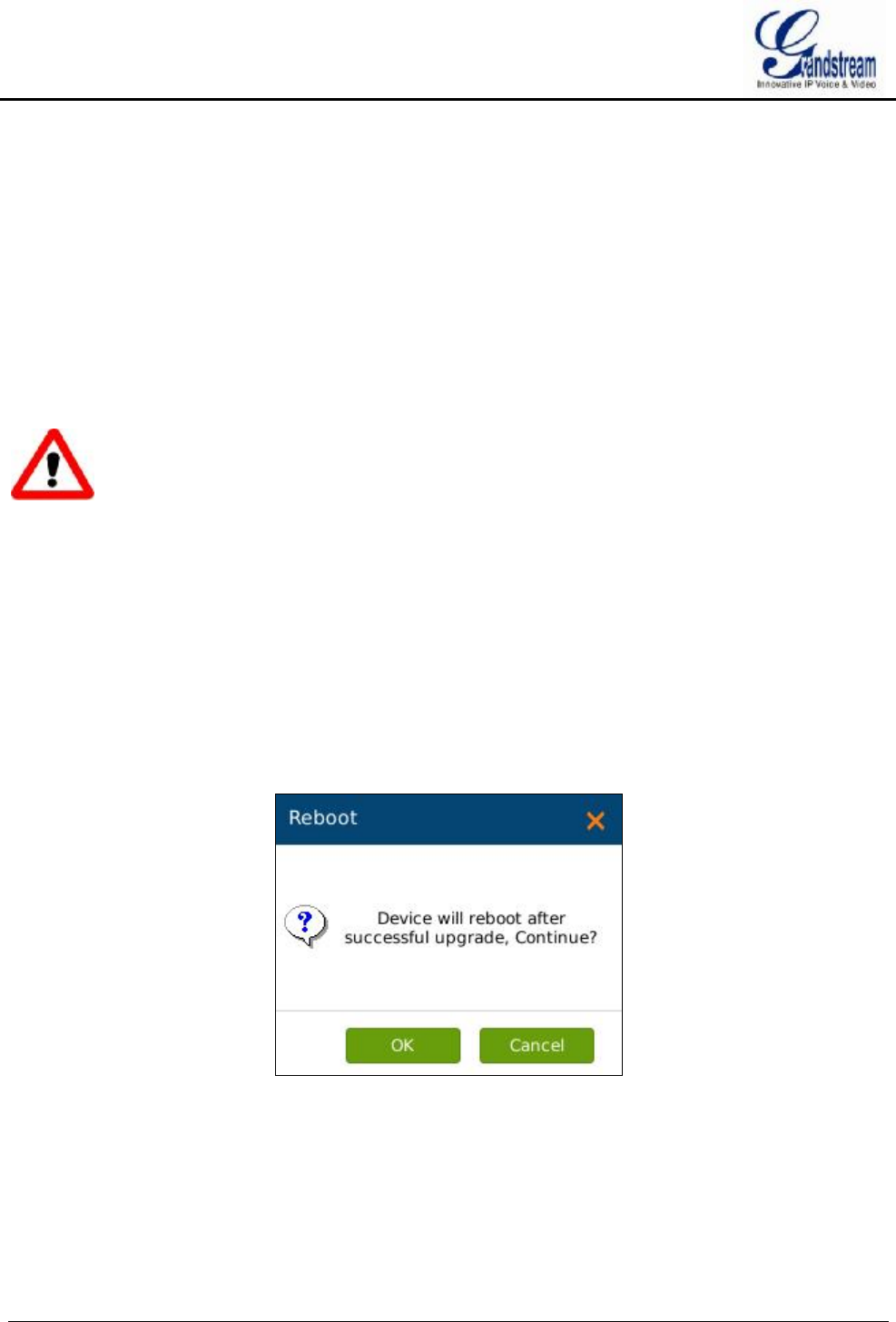
GVR3550/GVR3552 User Manual Page 117 of 125
FACTORY RESET
Users could reset factory settings via the following ways: Reset via local GUI, via Web page, via the reset
button on the back panel of GVR3550/GVR3552. Factory reset will delete configuration info and syslog info,
the HDD data and videos will not be deleted.
Warning!
Ø Factory Reset will erase all GVR3550/GVR3552 configuration info. Please back up all settings or print
useful info before making the following operations. If users lost all parameters or records, Grandstream
will take no responsibility for the damage or loss.
RESET VIA LOCAL GUI
Go to GVR3550/GVR3552 GUI Main Menu->Maintenance->Reset & Reboot, select "Erase All Data" or
"Retain Network Data Only" and click on the "Reset" button to bring up the prompt box as shown below.
Click "OK" to reboot the device and restore factory settings.
Figure 97 Factory Reset on GUI Page
RESET VIA WEB PAGE
Go to GVR3550/GVR3552 Web page Main Menu->Maintenance->Reset & Reboot, select "Erase All Data"
or "Retain Network Data Only" and click on the "Reset" button to bring up the prompt box as shown below.
Click "OK" to reboot the device and restore factory settings.

GVR3550/GVR3552 User Manual Page 118 of 125
Figure 98 Factory Reset on Web Page
RESET VIA BUTTON
There is a Reset button on the back panel of GVR3550/GVR3552 as shown in figure 2 and figure 3, long
press the button for more than 10 seconds to reboot and restore to factory reset.

GVR3550/GVR3552 User Manual Page 119 of 125
EXPERIENCING GVR3550/GVR3552
Please visit our website: http://www.grandstream.com to receive the most up-to-date updates on firmware
releases, additional features, FAQs, documentation and news on new products.
We encourage you to browse our product related documentation, FAQs and User and Developer Forum for
answers to your general questions. If you have purchased our products through a Grandstream Certified
Partner or Reseller, please contact them directly for immediate support.
Our technical support staff is trained and ready to answer all of your questions. Contact a technical support
member or submit a trouble ticket online to receive in-depth support.
Thank you again for purchasing Grandstream Enterprise Application phone, it will be sure to bring
convenience and color to both your business and personal life.

GVR3550/GVR3552 User Manual Page 120 of 125
APPENDIX
FAQs
The issues 1-21 might be caused by the reasons listed below each issue.
1. The GVR3550/GVR3552 is unable to start properly after normal startup
Unmatched input power
The power cables is not connected properly
Damaged power supply
System upgrade errors
Damaged HDD or HDD cables
Front panel error
Damaged mainboard
2. GVR3550/GVR3552 reboots automatically or crashes frequently in a few minutes after
startup.
Unstable input power or low voltage
No enough power
HDD power line connection error
Bad HDD tracks or damaged HDD line
Unstable IPC video signal
Poor heat dissipation, too much dust, poor running environment.
Hardware failure
3. Cannot detect HDD after startup, it might be caused by the following reasons.
HDD power line is not connected
Damaged HDD cable
Damaged HDD
Damaged SATA port on mainboard
4. No video output
Unmatched programs, please update system.
Image brightness is 0, please restore the default settings.
Hardware failure
5. Unable to search video when local playback

GVR3550/GVR3552 User Manual Page 121 of 125
Damaged HDD cables
Updated program is not compatible with the system
Damaged HDD
Full HDD
The video you want to search has been overwritten.
The video is not being played.
6. Blurred screen when search local video
Restart GVR3550/GVR3552 will generally solve these issues: data reading error, small
code stream, mosaics in fullscreen when playback.
Damaged HDD cable
HDD error
Hardware failure
Connected to many cameras
7. Wrong time display
Wrong time or time zone settings
The cell button is not installed properly
Low voltage
Damaged crystal oscillator
8. GVR3550 can’t control PTZ
IPC PTZ error
Wrong PTZ decoding settings, wiring, installation
Wrong cable connection
Wrong PTZ settings
Unmatched PTZ decoder with GVR3550/GVR3552 protocol
Unmatched PTZ decoder with GVR3550/GVR3552 address
9. Unable to login the Web page
Unable to install PC client or the page can’t be displayed normally.
The operation systems is win98 or win me: It is recommended to update the operating
system to win 2000sp4 and higher.
Network connection error
Wrong network settings
Incorrect username or password
10. Mosaics or no images on screen when preview or playback
Poor Internet connection
PC client limit
The login user has no monitoring privilege

GVR3550/GVR3552 User Manual Page 122 of 125
Connected to many cameras
11. Unstable Internet connection
Unstable network
IP address conflict
MAC address conflict
Unstable network card on PC
12. USB backup error
CPU usage is too high, please stop recording then backup.
Data volume exceeds backup capacity
Incompatible backup devices
Damaged backup devices
13. Unable to close alarm
Wrong alarm settings
Open alarm manually
Input device errors or wrong connection
Wrong version, please upgrade
14. The alarm doesn't work
Wrong alarm settings
Wrong cables connection
One alarm is connected to two circuits the same time
15. Unable to control GVR3550/GVR3552 via remote control
Remote control distance is too far or the control angle is too tilt
Low batteries
Damaged control/front panel
16. Insufficient record time
Large stream caused by poor quality of the camera, dirty camera Lens, backlight
installation.
Insufficient HDD capacity
Damaged HDD
17. Unable to play downloaded backup file
You have not installed player or unplugged the external storage device improperly.
18. No images, black screen
Check IP, port, username/password of the remote camera.

GVR3550/GVR3552 User Manual Page 123 of 125
Check the network connection with the remote camera.
19. Display screen is not complete
Check the resolution the LCD supports. If the GVR resolution is 1920*1080, the LCD
should support 1920*1080 resolution.
20. No LCD HDMI output
Check the HDMI cable and whether LCD works in HDMI mode.
21. Record lag on PC in multi-cameras mode
Please check the network bandwidth, 100 MB is recommended and pay attention to the
PC performance. E.g.,16 cameras requires Quad Core CPU, discrete graphics, 2G
memory and high, 256M video memory and higher.
RECORDING TIME CALCULATION
Please confirm the HDD has been installed when install GVR3550/GVR3552 the first time.
HDD Capacity formula is:
Total HDD Space (M) = the amount of cameras * required time (Hour) * the HDD space occupied per
hour(M/H)
From the formula above we could conclude the recording time formula:
Recording Time (hour ) = Total HDD Space (M)/the HDD space occupied per hour(M/H)*the amount
of cameras
GVR3550/GVR3552 is equipped with MPEG4/H.264 compression technique, its dynamic range is quite
large thus the HDD capacity calculation based on assessing the video file size each camera recorded per
hour.
e.g.:
The video one single camera records per hour takes up 200M/H in HDD, use GVR3550 to record
synchronously with 12 cameras.
Record Time (hour) = 2*4*1024*1024/200(M/H)*12=3495.25(Hour)»145.6(Day)
COMPATIBLE HDD
Manufacturer Model Capacity
Seagate ST3000VX000 3T
Seagate ST500DM002 500G
Seagate ST2000VX000 2T
Seagate ST1000VX000 1T
Western Digital WD40EZRX-00SPEB0 4T
Western Digital WD20EZRX 2T

GVR3550/GVR3552 User Manual Page 124 of 125
Western Digital WD10EURX-73FH1Y0 1T
Western Digital WD20EURS-73TLHY0 2T
Western Digital WD5000AVDS 500G
Western Digital WD5000AAKX 500G
Western Digital WD5000AVDS-63U7B1 500G
Toshiba DT01ACA050 500G
Toshiba DT01ACA200 2T
HGST HUA723020ALA640 2T