Grandstream Networks GXP1400 IP Phone User Manual
Grandstream Networks, Inc IP Phone Users Manual
UserManual.wiki
>
Grandstream Networks
>
GXP1400 User Manual
Users Manual
Navigation menu
Upload a User Manual
Namespaces
Wiki Guide
HTML
PDF
Info
Views
User Manual
Discussion / Help
Navigation

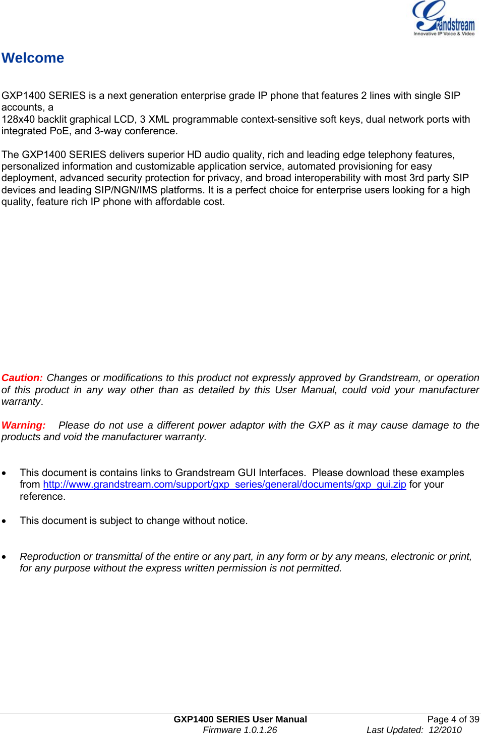
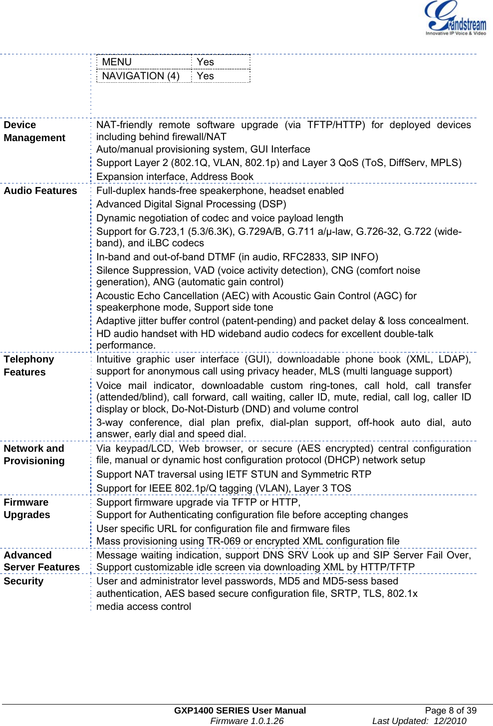

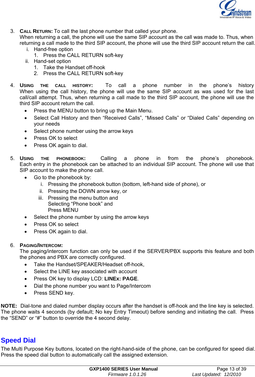
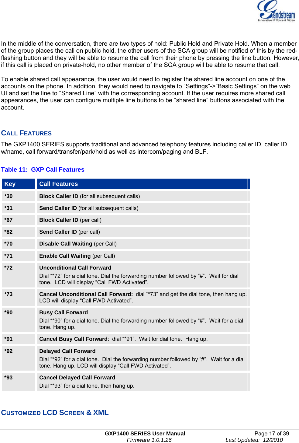
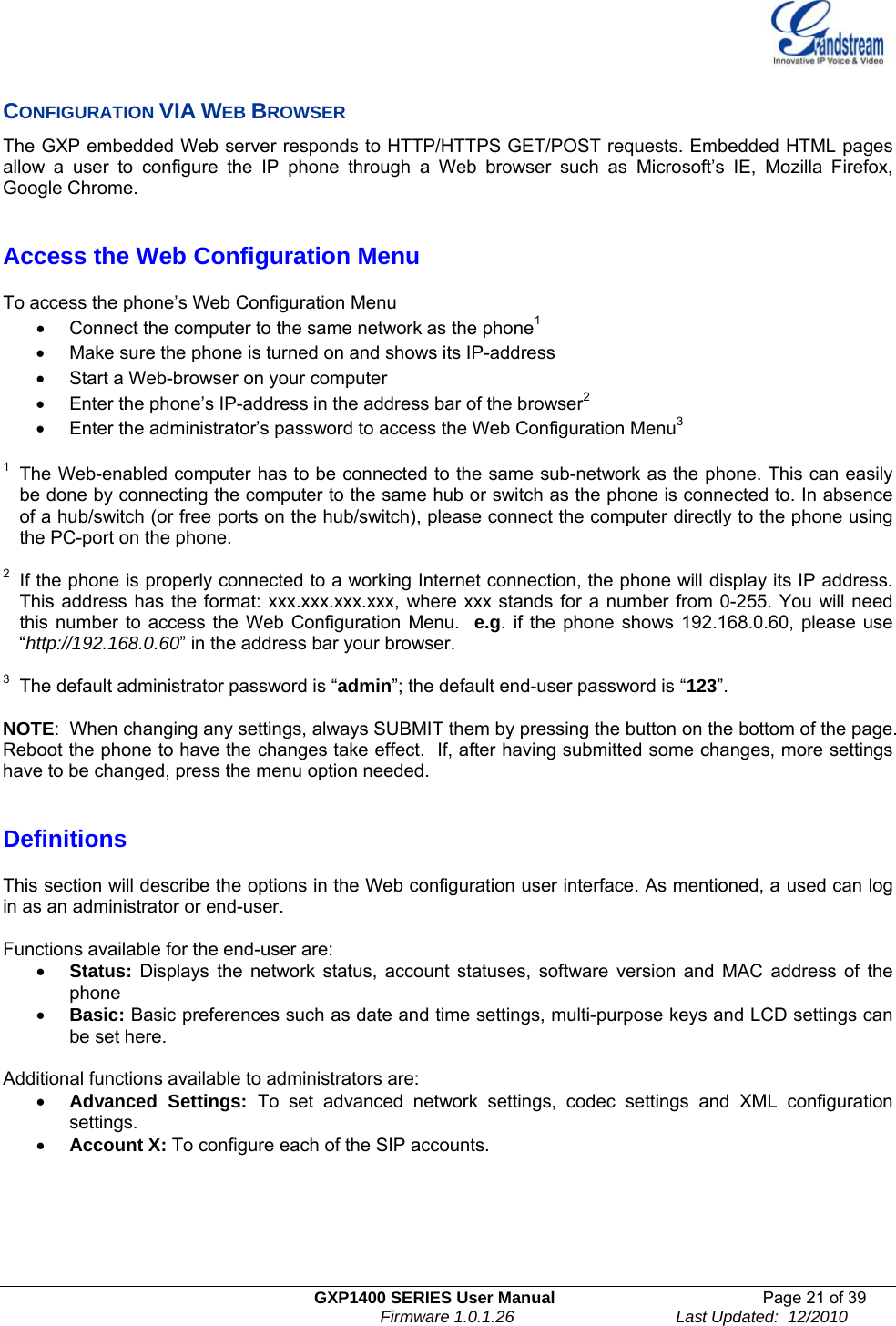
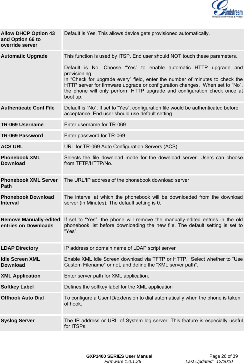
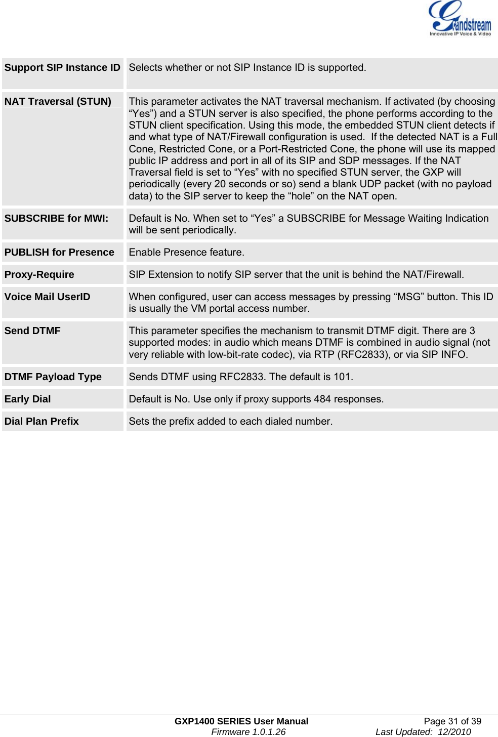
![GXP1400 SERIES User Manual Page 23 of 39 Firmware 1.0.1.26 Last Updated: 12/2010 Line Keys x This allows the user to configure the account mapped to each line key, as well as enabling SCA (Shared Call Appearance) for the line. Options available for Key Mode are : 1. Line 2. Shared Line Multi Purpose Key X These options are used to assign a function to the corresponding multi purpose key.Options available are: 1. “Speed Dial”. 2. “BLF” (Busy Lamp Field). This option has to be supported on the PBX and it indicates the status of the extension. The three possible states are idle (green), busy (red), ringing (blinking red). 3. “Presence Watcher”. This option has to be supported by a presence server and it is tied to the “Do not disturb” status of the phone. 4. “Eventlist BLF”. This option is similar to the BLF option but in this case the PBX collects the information from the phones and sends it out in one single notify message. Each function is connected to one of the accounts and has a target user ID. Time Zone This parameter controls the date/time display according to the specified time zone. Self-Defined Time Zone This parameter allows the users to define their own time zone. The syntax is: std offset dst [offset], start [/time], end [/time] Default is set to: MTZ+6MDT+5,M3.2.0,M11.1.0 MTZ+6MDT+5, This indicates a time zone with 6 hours offset with 1 hour ahead which is U.S central time. If it is positive (+) if the local time zone is west of the Prime Meridian (A.K.A: International or Greenwich Meridian) and negative (-) if it is east. M3.2.0,M11.1.0 The 1st number indicates Month: 1,2,3.., 12 (for Jan, Feb, .., Dec) The 2nd number indicates the nth iteration of the weekday: (1st Sunday, 3rd Tuesday…) The 3rd number indicates weekday: 0,1,2,..,6( for Sun, Mon, Tues,..,Sat) Therefore, this example is the DST which starts from the second Sunday of March to the 1st Sunday of November. Weather Update Settings to customize the dispay of weather via: • City Code – Enter city zip code • Update Interval – Refresh time in minutes • Degree Unit – Select either Fahrenheit or Celsius This is displayed when pressing the ‘SwitchSCR’ soft-key once. Stock Update Settings to customize the display order of major stock indices. This is displayed when pressing the ‘SwitchSCR’ soft key twice. Currency Update Settings to customize the display order of currency updates of foreign currency intoUS dollars. This is displayed when pressing the ‘Switch SCR’ soft key three times. LCD Backlight Brightness Set the LCD brightness level. Range from 0 to 8 where 0 means off and 8 means the brightest. LCD Contrast Set LCD contrast. Range from 0 to 20.](https://usermanual.wiki/Grandstream-Networks/GXP1400/User-Guide-1405583-Page-23.png)
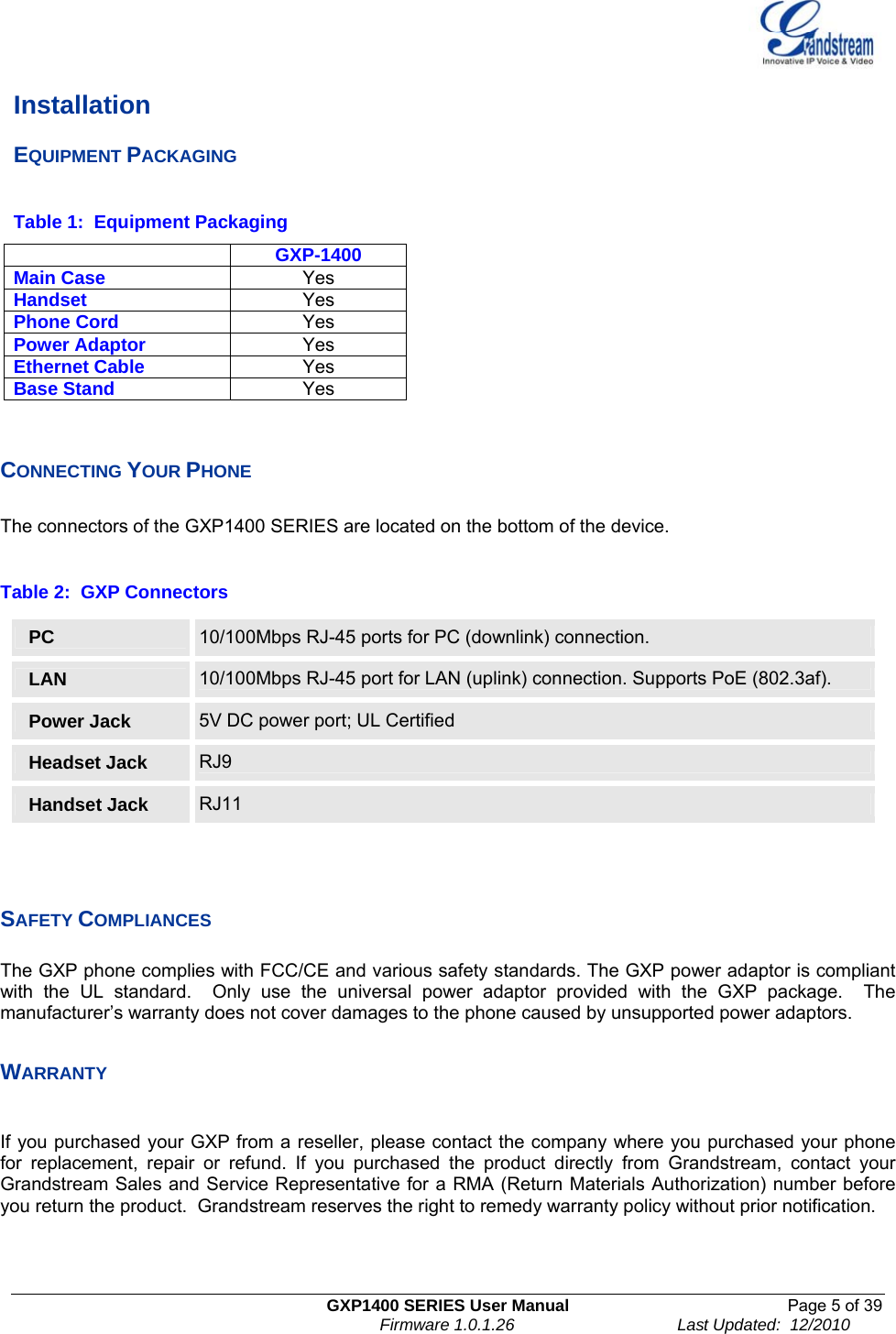
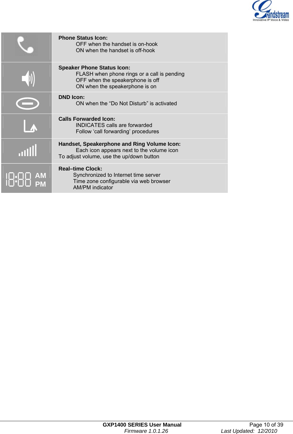
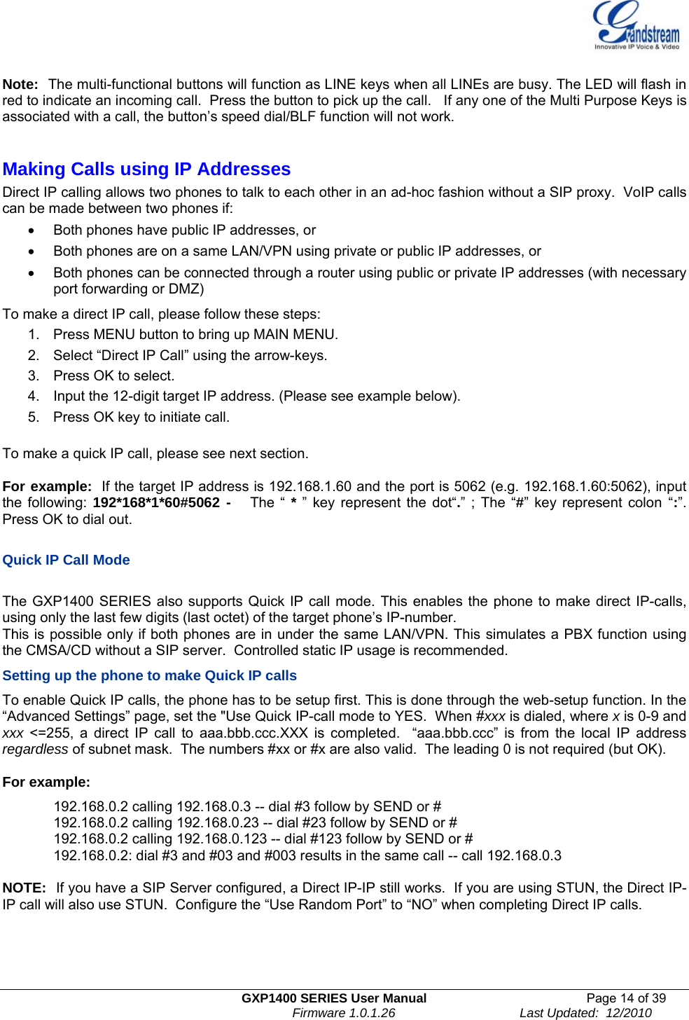
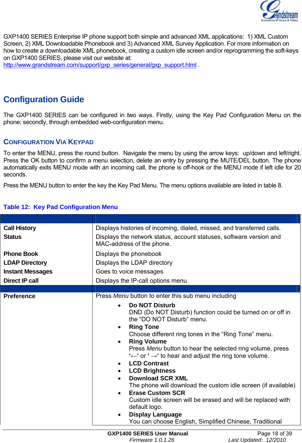
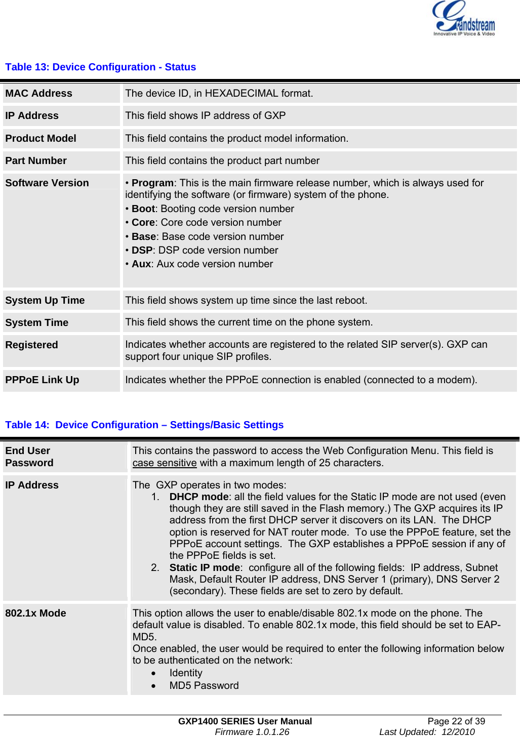
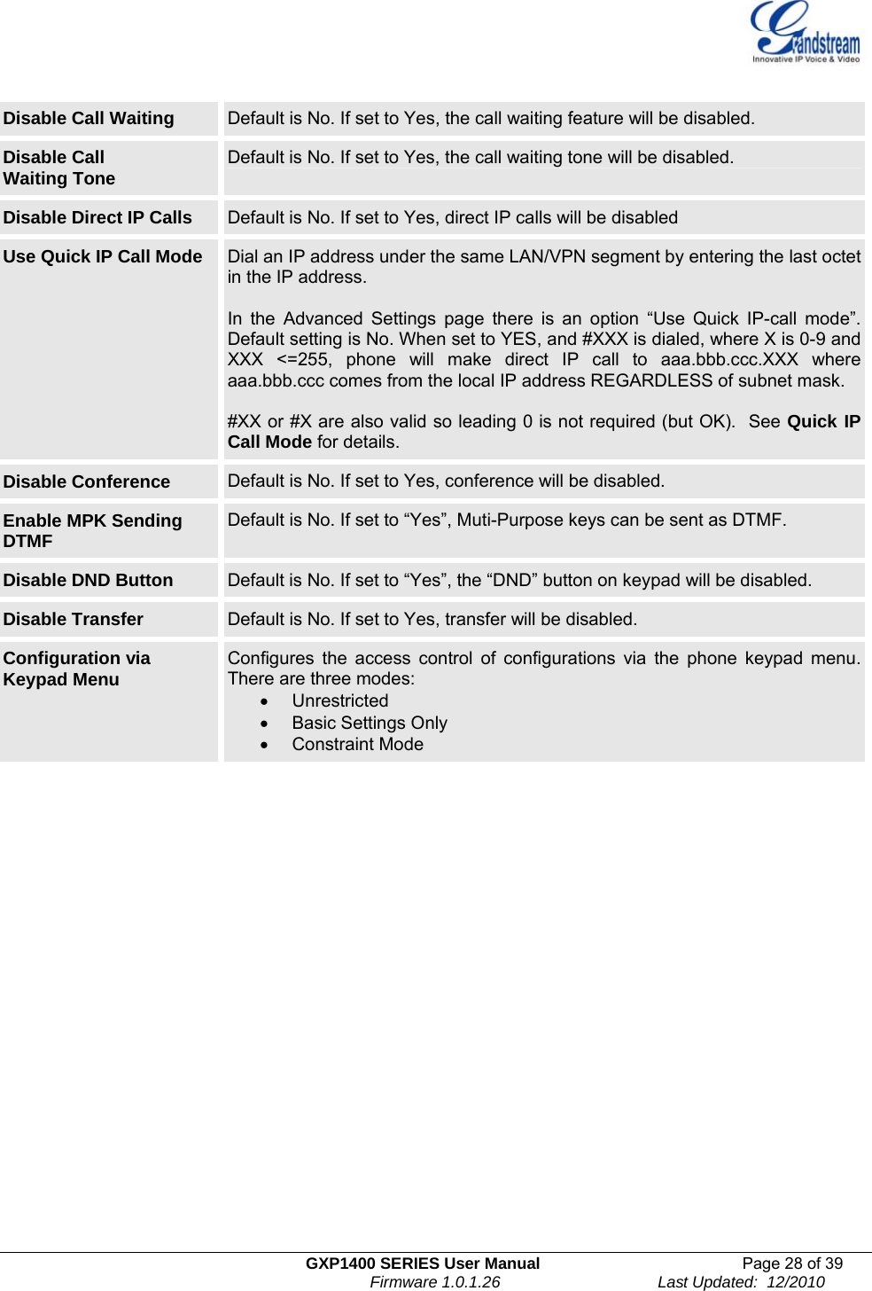
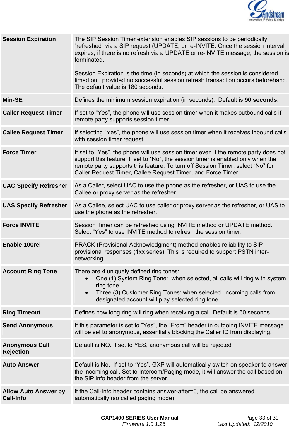
![GXP1400 SERIES User Manual Page 27 of 39 Firmware 1.0.1.26 Last Updated: 12/2010 Syslog Level Select the ATA to report the log level. Default is NONE. The level is one of DEBUG, INFO, WARNING or ERROR. Syslog messages are sent based on the following events: • product model/version on boot up (INFO level) • NAT related info (INFO level) • sent or received SIP message (DEBUG level) • SIP message summary (INFO level) • inbound and outbound calls (INFO level) • registration status change (INFO level) • negotiated codec (INFO level) • Ethernet link up (INFO level) • SLIC chip exception (WARNING and ERROR levels) • memory exception (ERROR level) The Syslog uses USER facility. In addition to standard Syslog payload, it contains the following components: GS_LOG: [device MAC address][error code] error message For example: May 19 02:40:38 192.168.1.14 GS_LOG: [00:0b:82:00:a1:be][000]. Ethernet link is up. NTP server This parameter defines the URI or IP address of the NTP (Network Time Protocol) serve. It is used to display the current date/time. SSL Certificate This defines the SSL certificate needed to access certain websites. SSL Private Key This defines the SSL Private key. SSL Private Key Password This defines the SSL private key password. Distinctive Ring Tone Caller ID must be configured. Select a Distinctive Ring Tone 1 through 3 for a particular Caller ID. The GXP will ONLY use selected ring tones for particular Caller IDs. For all other calls, the GXP will use System Ring Tone. When selected and no Caller ID is configured, the selected ring tone will be used for all incoming calls. System Ring Tone System ring tone. Default is North American standard. Adjust system ring tone frequencies and cadences based on local telecom standard. Call Progress Tones Using these settings, users can configure ring or tone frequencies based on parameters from local telecom. By default, they are set to North American standard. Frequencies should be configured with known values to avoid uncomfortable high pitch sounds. Syntax: f1=val,f2=val[,c=on1/off1[-on2/off2[-on3/off3]]]; (Frequencies are in Hz and cadence on and off are in 10ms) ON is the period of ringing (“On time” in ‘ms’) while OFF is the period of silence. In order to set a continuous ring, OFF should be zero. Otherwise it will ring ON ms and a pause of OFF ms and then repeat the pattern. Up to three cadences are supported.](https://usermanual.wiki/Grandstream-Networks/GXP1400/User-Guide-1405583-Page-27.png)
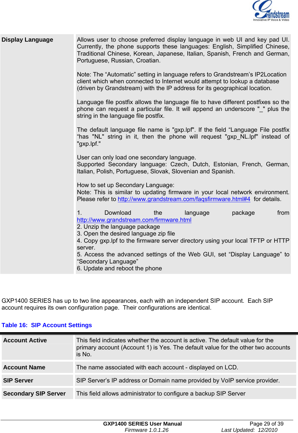
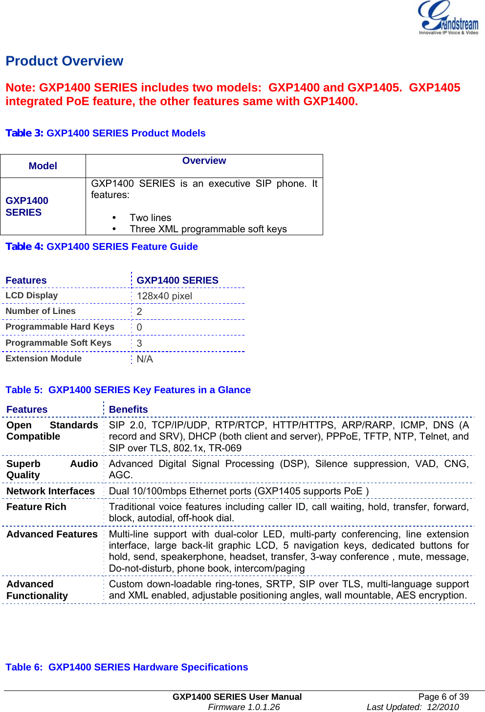
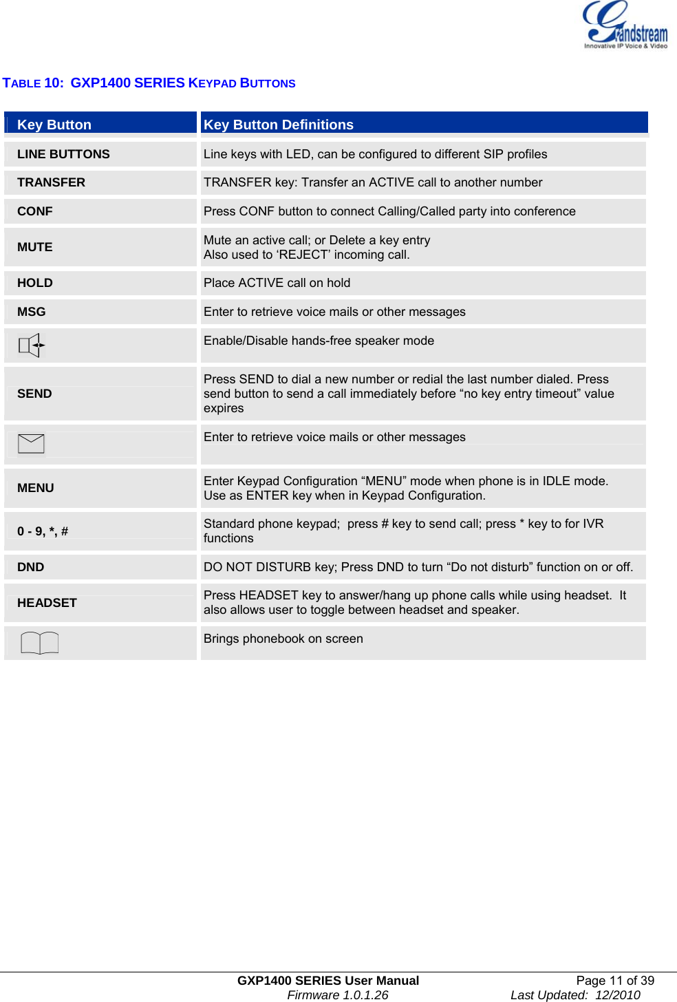
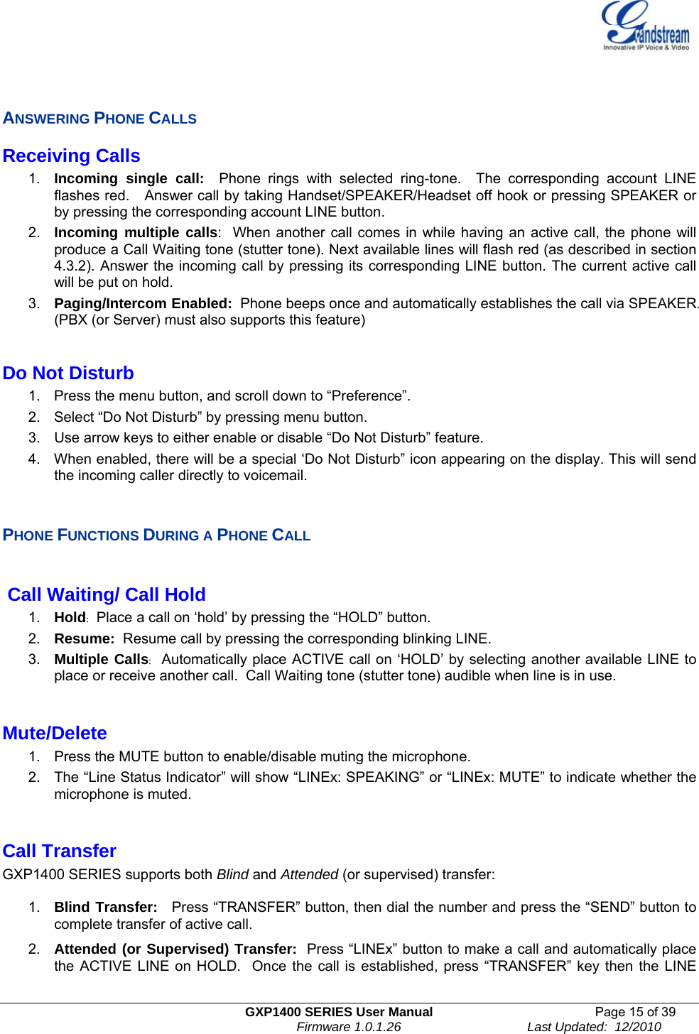
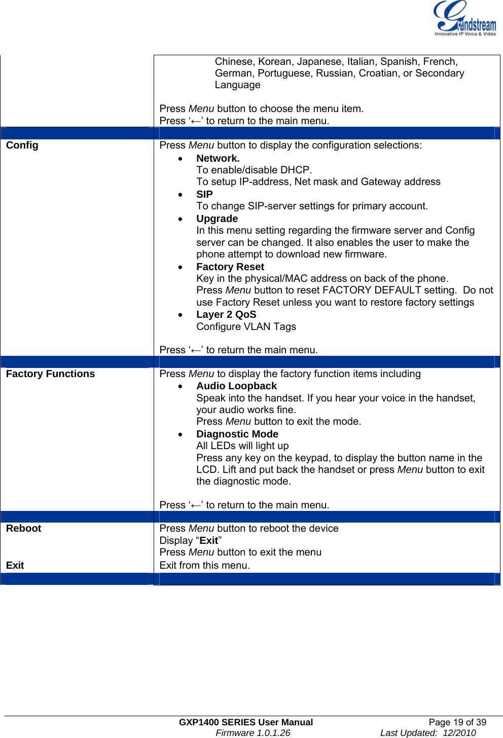
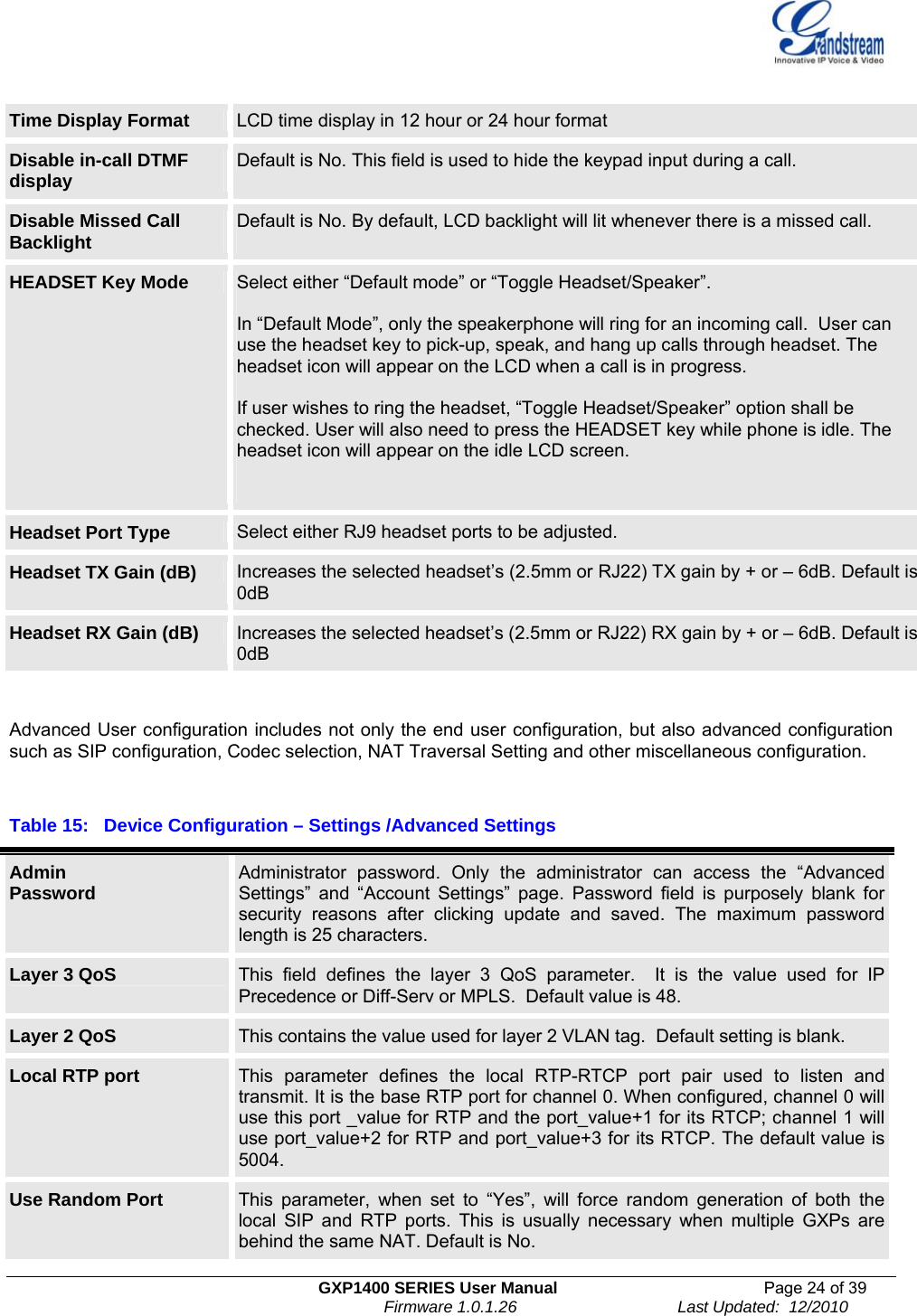
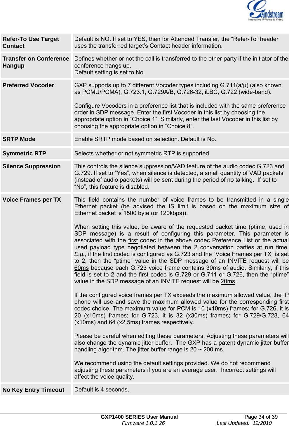
![GXP1400 SERIES User Manual Page 32 of 39 Firmware 1.0.1.26 Last Updated: 12/2010 Dial Plan Dial Plan Rules: 1. Accepted Digits: 1,2,3,4,5,6,7,8,9,0 , *, #, A,a,B,b,C,c,D,d 2. Grammar: x - any digit from 0-9; a) xx+ - at least 2 digit numbers b) xx. - only 2 digit numbers c) ^ - exclude d) [3-5] - any digit of 3, 4, or 5 e) [147] - any digit of 1, 4, or 7 f) <2=011> - replace digit 2 with 011 when dialing g) | - the OR operand • Example 1: {[369]11 | 1617xxxxxxx} Allow 311, 611, and 911 or any 10 digit numbers with leading digits 1617 • Example 2: {^1900x+ | <=1617>xxxxxxx} Block any number of leading digits 1900 or add prefix 1617 for any dialed 7 digit numbers • Example 3: {1xxx[2-9]xxxxxx | <2=011>x+} Allows any number with leading digit 1 followed by a 3 digit number, followed by any number between 2 and 9, followed by any 7 digit number OR Allows any length of numbers with leading digit 2, replacing the 2 with 011 when dialed. 3. Default: Outgoing – {x+} Allow any length of numbers. Example of a simple dial plan used in a Home/Office in the US: { ^1900x. | <=1617>[2-9]xxxxxx | 1[2-9]xx[2-9]xxxxxx | 011[2-9]x. | [3469]11 } Explanation of example rule (reading from left to right): • ^1900x. - prevents dialing any number started with 1900 • <=1617>[2-9]xxxxxx - allows dialing to local area code (617) numbers by dialing7 numbers and 1617 area code will be added automatically • 1[2-9]xx[2-9]xxxxxx |- allows dialing to any US/Canada Number with 11 digits length • 011[2-9]x. - allows international calls starting with 011 • [3469]11 - allow dialing special and emergency numbers 311, 411, 611 and 911Note: In some cases where the user wishes to dial strings such as *123 to activate voice mail or other applications provided by their service provider, the * should be predefined inside the dial plan feature. An example dial plan will be: { *x+ } which allows the user to dial * followed by any length of numbers. BLF Call-pickup Prefix Default is ‘**”. This prefix is prepended when answering call with BLF key. Delayed Call Forward Wait Time Time waited before the call is forward to a number or VM. Default is 20 seconds. Enable Call Features Default is Yes. If set to “No”, Call transfer, Call Forwarding & Do-Not-Disturb are supported locally provided ITSP support those features. In addition, “ForwardAll” softkey will be hidden if call feature code is disabled for Account 1. Call Log User can choose to disable Call Log and what kind of calls to log.](https://usermanual.wiki/Grandstream-Networks/GXP1400/User-Guide-1405583-Page-32.png)
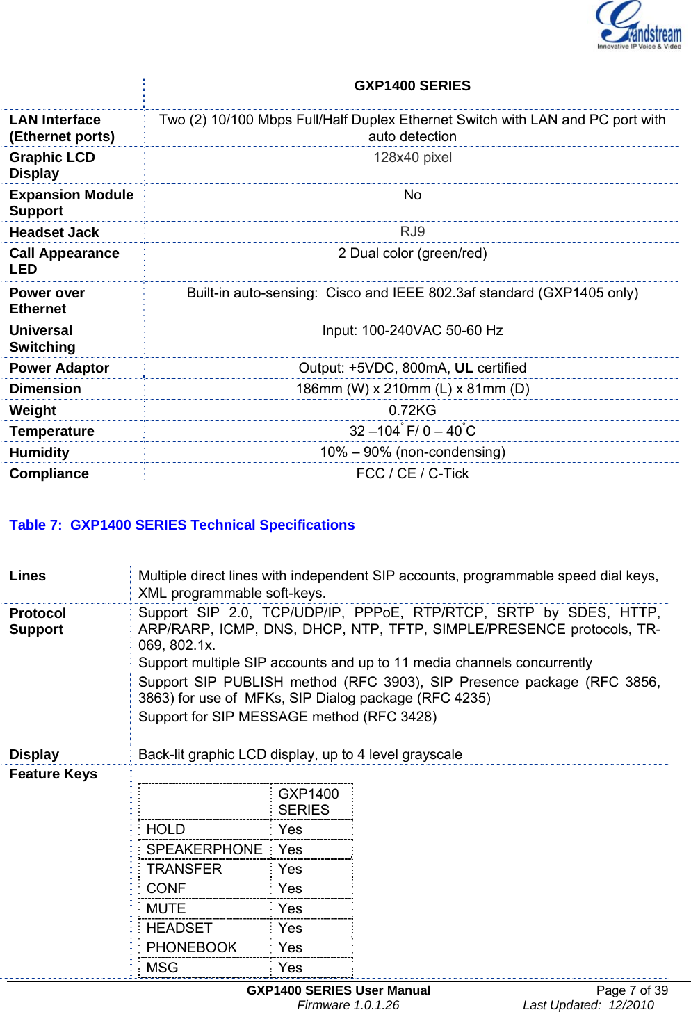
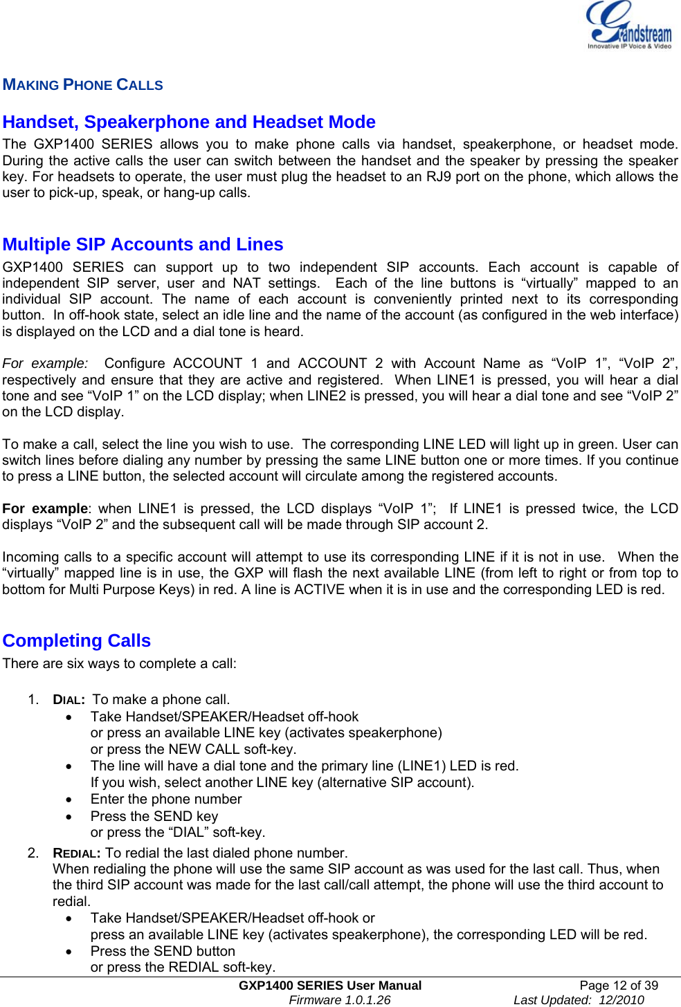
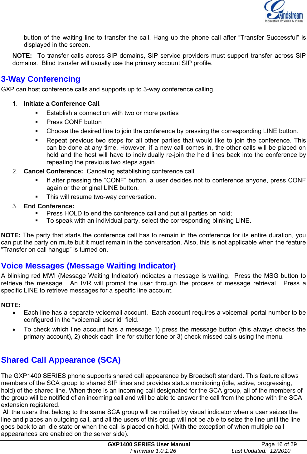
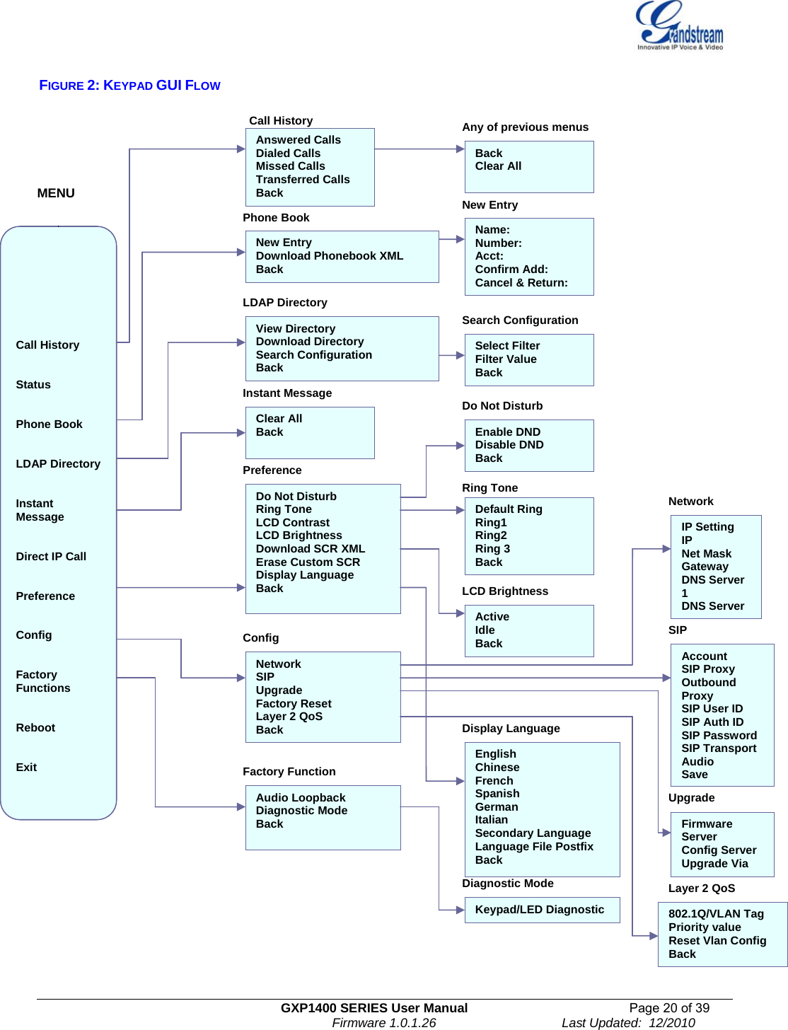
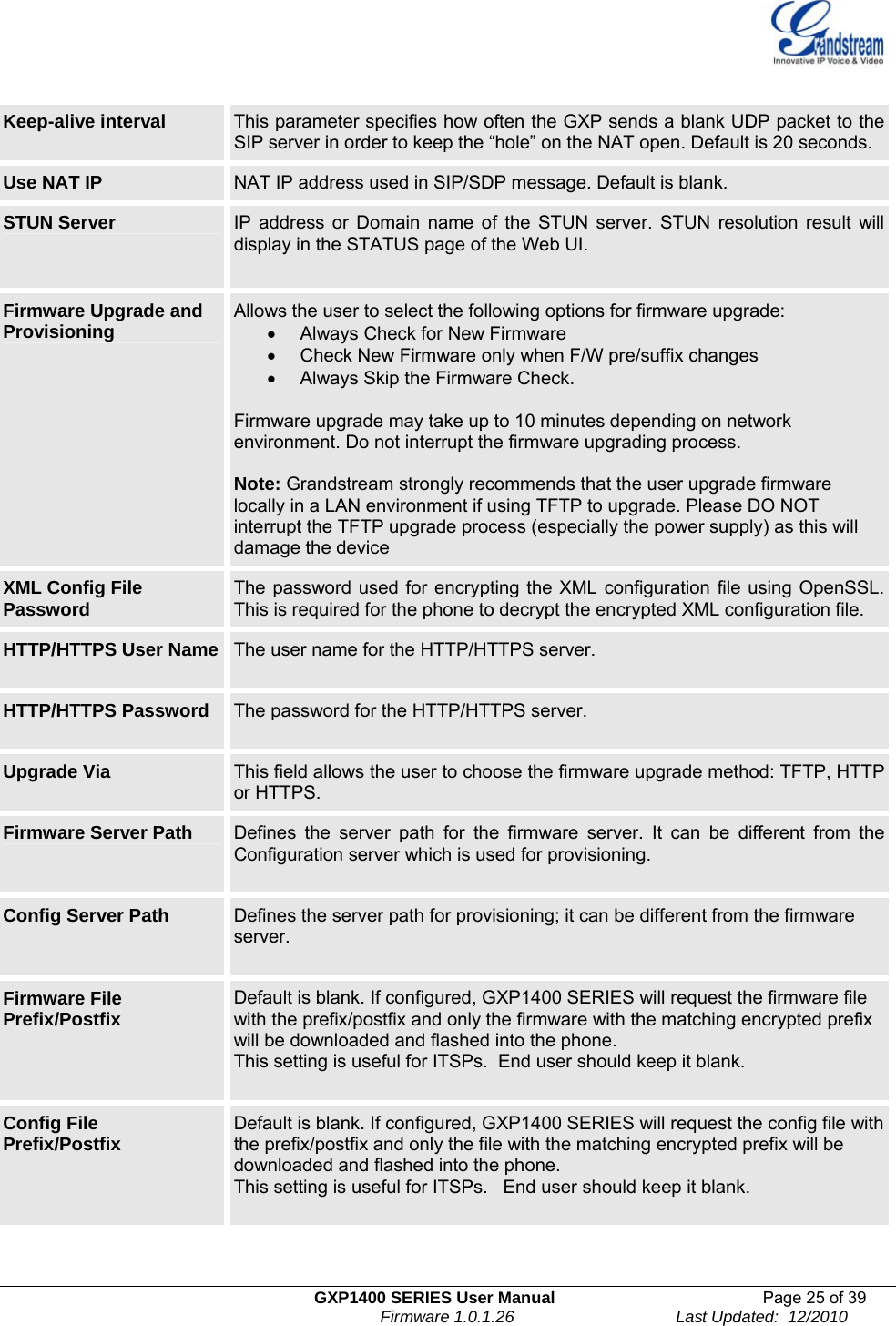
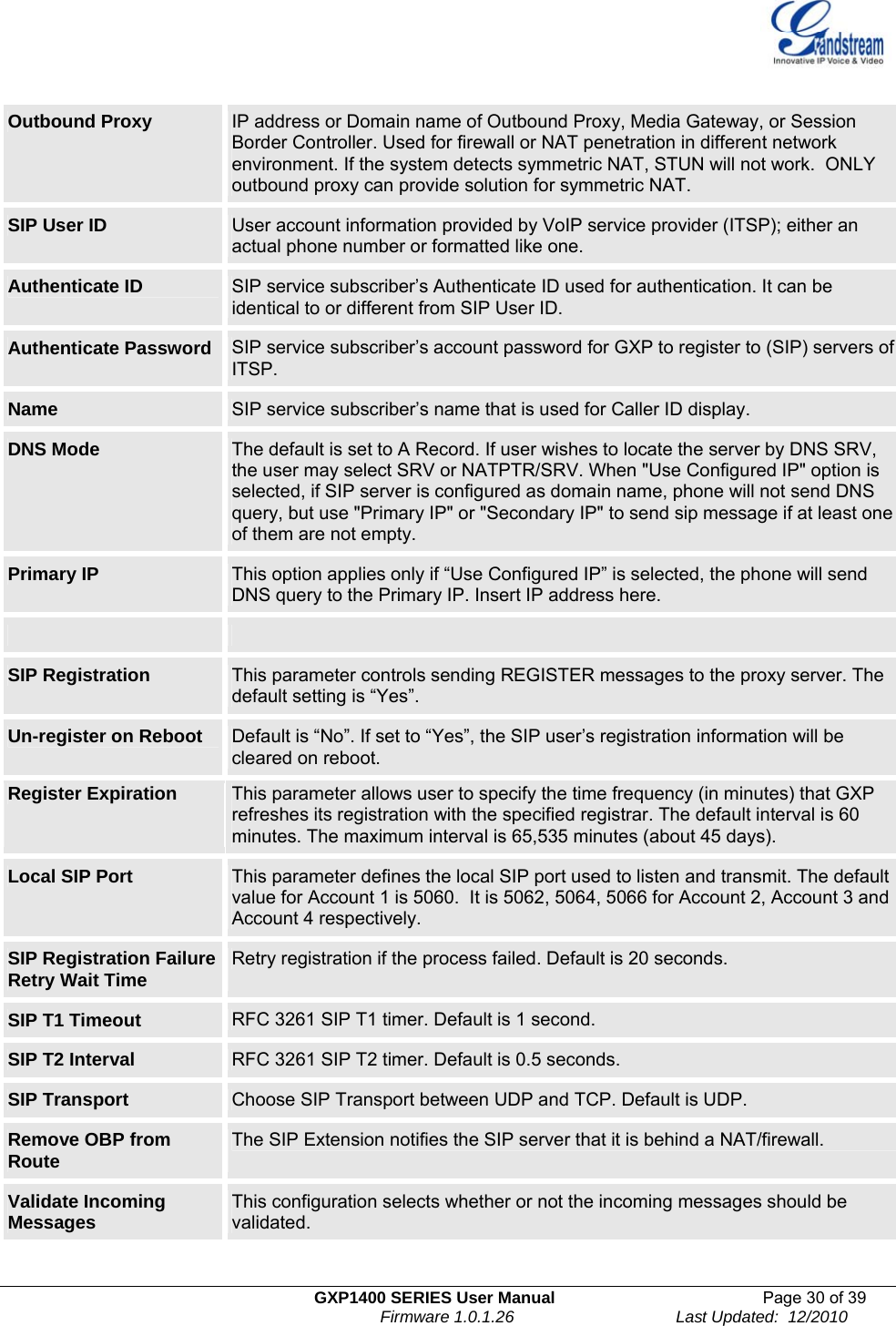
![GXP1400 SERIES User Manual Page 37 of 39 Firmware 1.0.1.26 Last Updated: 12/2010 1. Unzip the file and put all of them under the root directory of the TFTP server. 2. The PC running the TFTP server and the GXP should be in the same LAN segment. 3. Go to File -> Configure -> Security to change the TFTP server's default setting from "Receive Only" to "Transmit Only" for the firmware upgrade. 4. Start the TFTP server, in the phone’s web configuration page 5. Configure the Firmware Server Path with the IP address of the PC 6. Update the change and reboot the unit User can also choose to download the free HTTP server from http://httpd.apache.org/ or use Microsoft IIS web server. NOTE: • When GXP phone boots up, it will send TFTP or HTTP request to download configuration file “cfg000b82xxxxxx”, where “000b82xxxxxx” is the MAC address of the GXP phone. This file is for provisioning purpose. For normal TFTP or HTTP firmware upgrades, the following error messages in a TFTP or HTTP server log can be ignored: “TFTP Error from [IP ADRESS] requesting cfg000b82023dd4 : File does not exist. Configuration File Download” CONFIGURATION FILE DOWNLOAD The GXP1400 SERIES can be configured via Web Interface as well as via Configuration File (binary or XML) through TFTP or HTTP/HTTPS. The “Config Server Path” is the TFTP or HTTP server path for the configuration file. It needs to be set to a valid URL, either in FQDN or IP address format. The “Config Server Path” can be the same or different from the “Firmware Server Path”. A configuration parameter is associated with each particular field in the web configuration page. A parameter consists of a Capital letter P and 2 to 4 digit numeric numbers. i.e., P2 is associated with “Admin Password” in the ADVANCED SETTINGS page. For a detailed parameter list, please refer to the corresponding configuration template of the firmware. Once the GXP1400 SERIES boots up (or re-booted), it will request a configuration file named “cfgxxxxxxxxxxxx” followed by a request for configuration XML file named “cfgxxxxxxxxxxxx.xml”, where “xxxxxxxxxxxx” is the MAC address of the device, i.e., “cfg000b820102ab”. The configuration file name should be in lower cases. For more details on XML provisioning, please refer to: http://www.grandstream.com/support/general/gs_xml_provisioning.pdf Managing Firmware and Configuration File Download When “Automatic Upgrade” is set to “Yes”, a Service Provider can use P193 (Auto Check Interval, in minutes, default and minimum is 60 minutes) to have the devices periodically check for upgrades at pre-scheduled time intervals. By defining different intervals in P193 for different devices, a Server Provider can manage and reduce the Firmware or Provisioning Server load at any given time.](https://usermanual.wiki/Grandstream-Networks/GXP1400/User-Guide-1405583-Page-37.png)