Grandstream Networks GXP2124 IP PHONE User Manual GXP2124 User Manual 1 0 0 01
Grandstream Networks, Inc. IP PHONE GXP2124 User Manual 1 0 0 01
UserManual.wiki
>
Grandstream Networks
>
GXP2124 User Manual
Users Manual
Navigation menu
Upload a User Manual
Namespaces
Wiki Guide
HTML
PDF
Info
Views
User Manual
Discussion / Help
Navigation

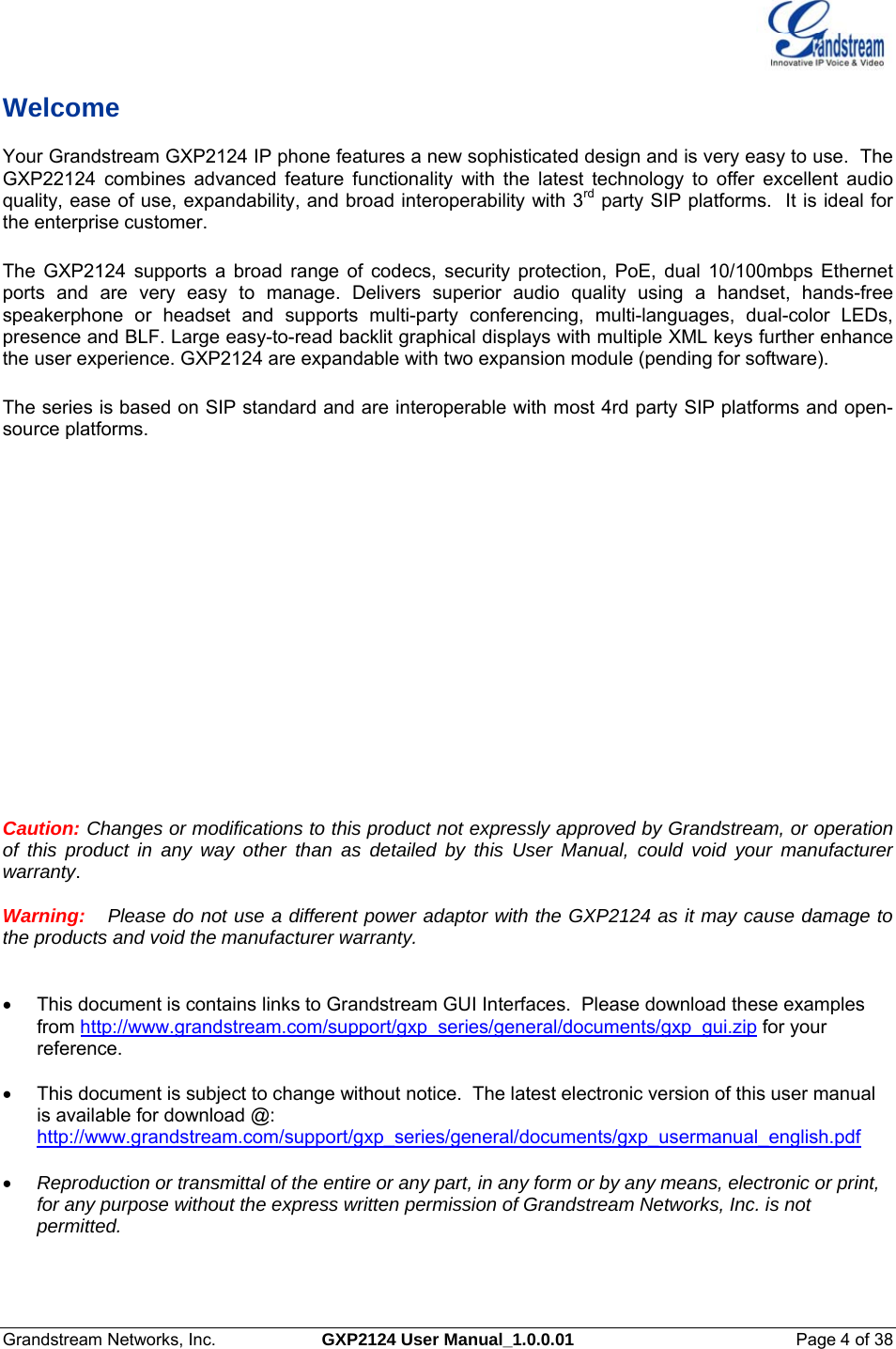
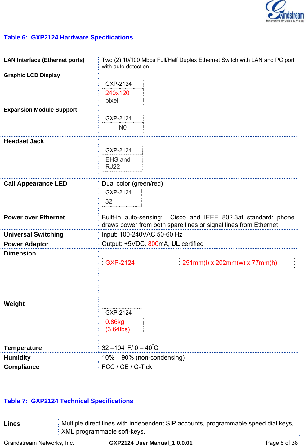
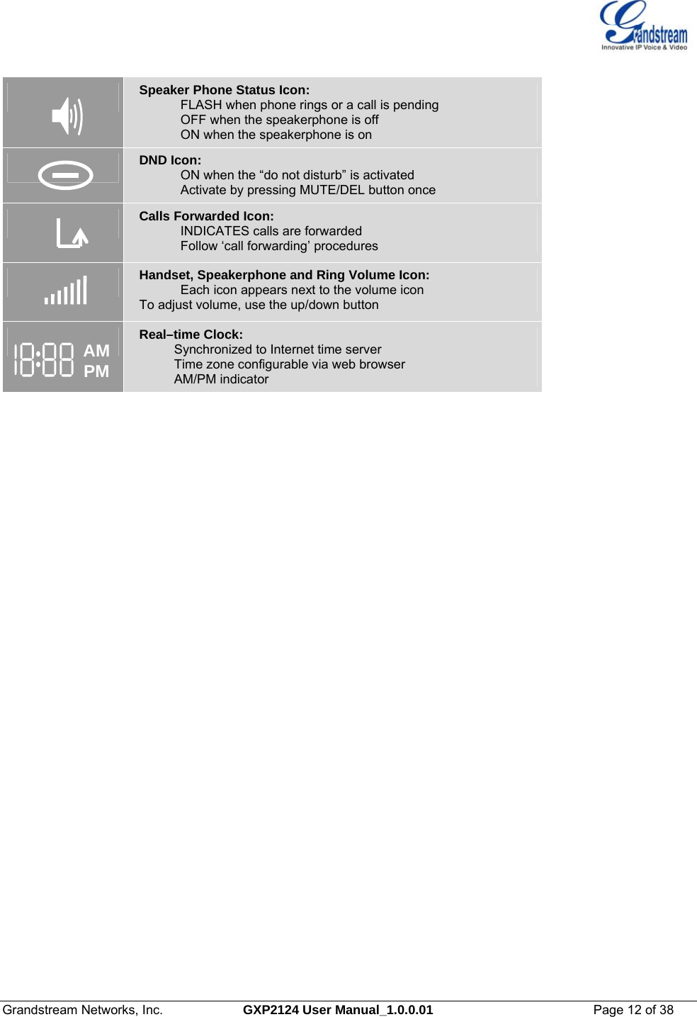
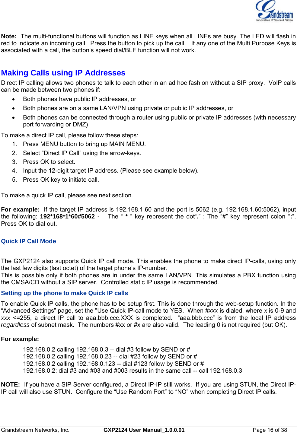
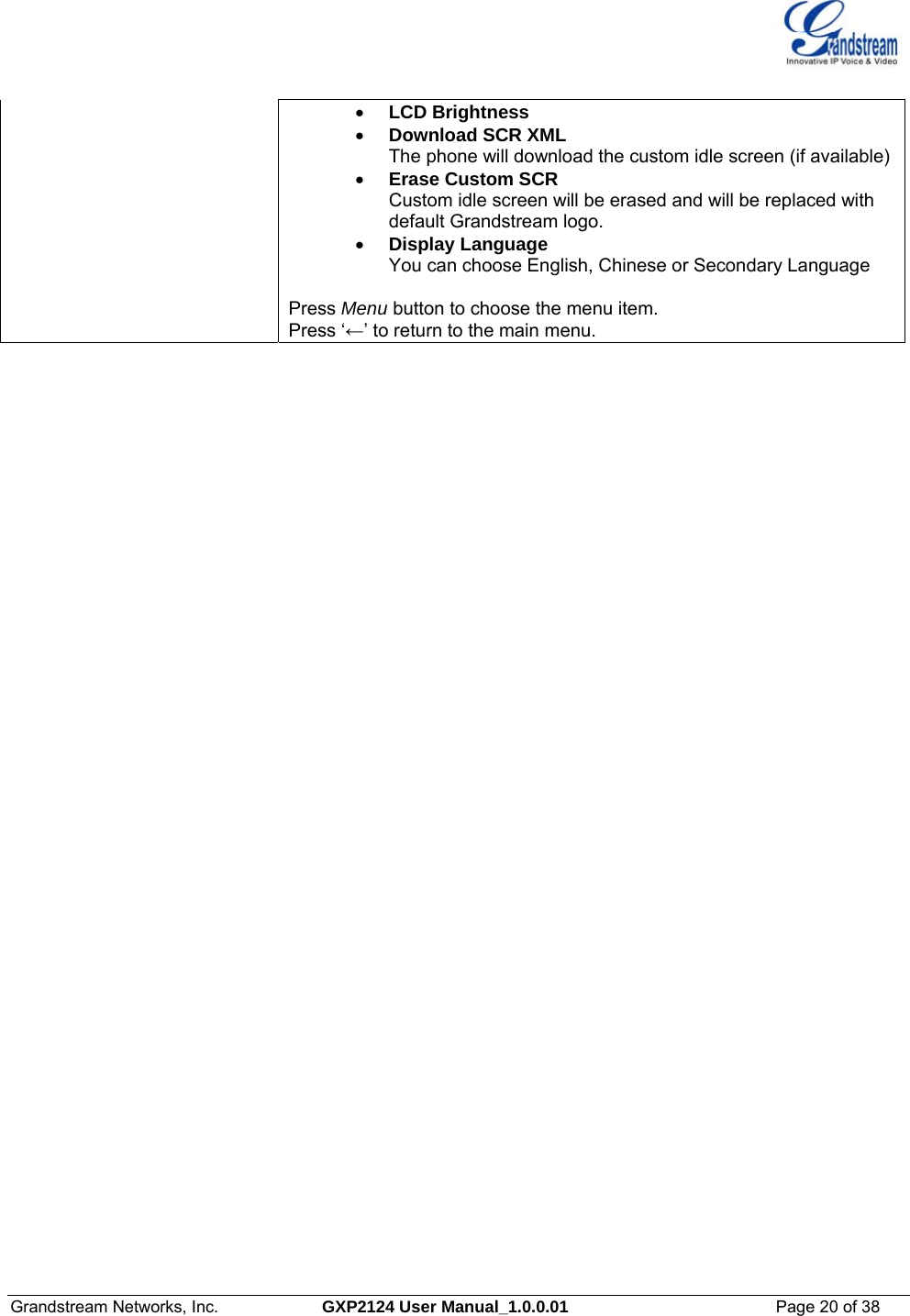
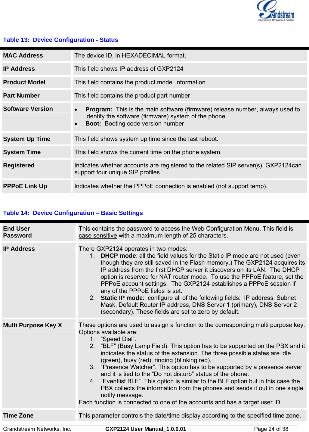
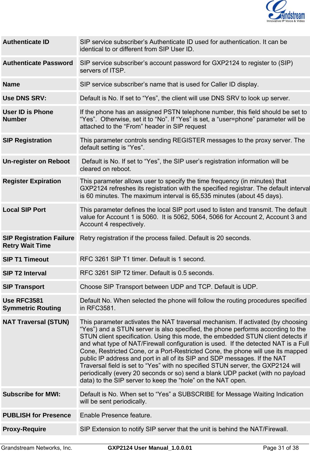
![Grandstream Networks, Inc. GXP2124 User Manual_1.0.0.01 Page 25 of 38 Time Display Format LCD time display in 12 hour or 24 hour format Daylight Savings Time This parameter controls time displayed in daylight savings time. If set to “Yes”, then the displayed time will be 1 hour ahead of normal time. The “Optional Rule” is configured to automatically adjust the Daylight Savings Time (DST) based on the rule set in this field. Rule Syntax: • start-time; end-time; saving • Both start-time and end-time have the same syntax: month,day,weekday,hour,minute o month: 1,2,3,..,12 (for Jan, Feb, .., Dec) o day: [+|-]1,2,3,..,31 o weekday: 1, 2, 3, .., 7 (for Mon, Tue, .., Sun), or 0 which means the daylight saving rule is not based on week days but based on the day of the month. o hour: hour (0-23), minute: minute (0-59) If “weekday” is 0, it means the date to start or end daylight saving is at exactly the given date. In that case, the “day” value must not be negative. If “weekday” is not zero and “day” is positive, then the daylight saving starts on the first “day” the iteration of the weekday (e.g.: 1st Sunday, 3rd Tuesday etc). If “weekday” is not zero and “day” is negative, then the daylight saving starts on the last “day” the iteration of the weekday (e.g.: last Sunday, 3rd last Tuesday etc). The saving is in the unit of minutes. The saving time may also be preceded by a negative (-) sign if subtraction is desired instead of addition. The default value is set for US, the “Automatic Daylight Saving Time Rule” shall be set to “3,2,7,2,0;11,1,7,2,0;60” Examples US/Canada where daylight saving time is applicable: 03,02,7,02,00;11,1,7,02,00;60 This means the daylight saving time starts from the second Sunday of March at 2AM and ends the first Sunday of November at 2AM. The saving is 60 minutes. LCD Backlight Brightness Set the LCD brightness level. Range from 0 to 8 where 0 means off and 8 means the brightest. LCD Contrast Set LCD contrast. Range from 0 to 20. Disable in-call DTMF display Default is No. This field is used to hide the keypad input during a call. Mute Speaker Ringer in Headset Mode Default is No. This field lets user to choose whether to ring the phone Speaker when headset is connected. Disable Missed Call Backlight Default is No. By default, LCD backlight will lit whenever there is a missed call. HEADSET Key Mode Set Default mode or choose Toggle Headset/Speaker. Advanced User configuration includes not only the end user configuration, but also advanced configuration such as SIP configuration, Codec selection, NAT Traversal Setting and other miscellaneous configuration. Table 15: Advanced Settings](https://usermanual.wiki/Grandstream-Networks/GXP2124/User-Guide-1639064-Page-25.png)
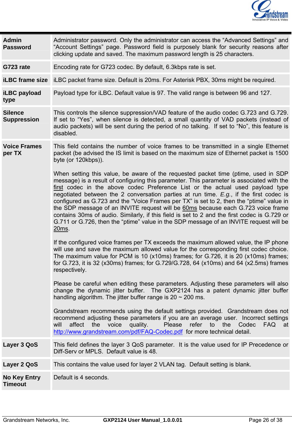
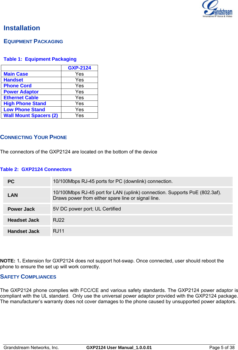
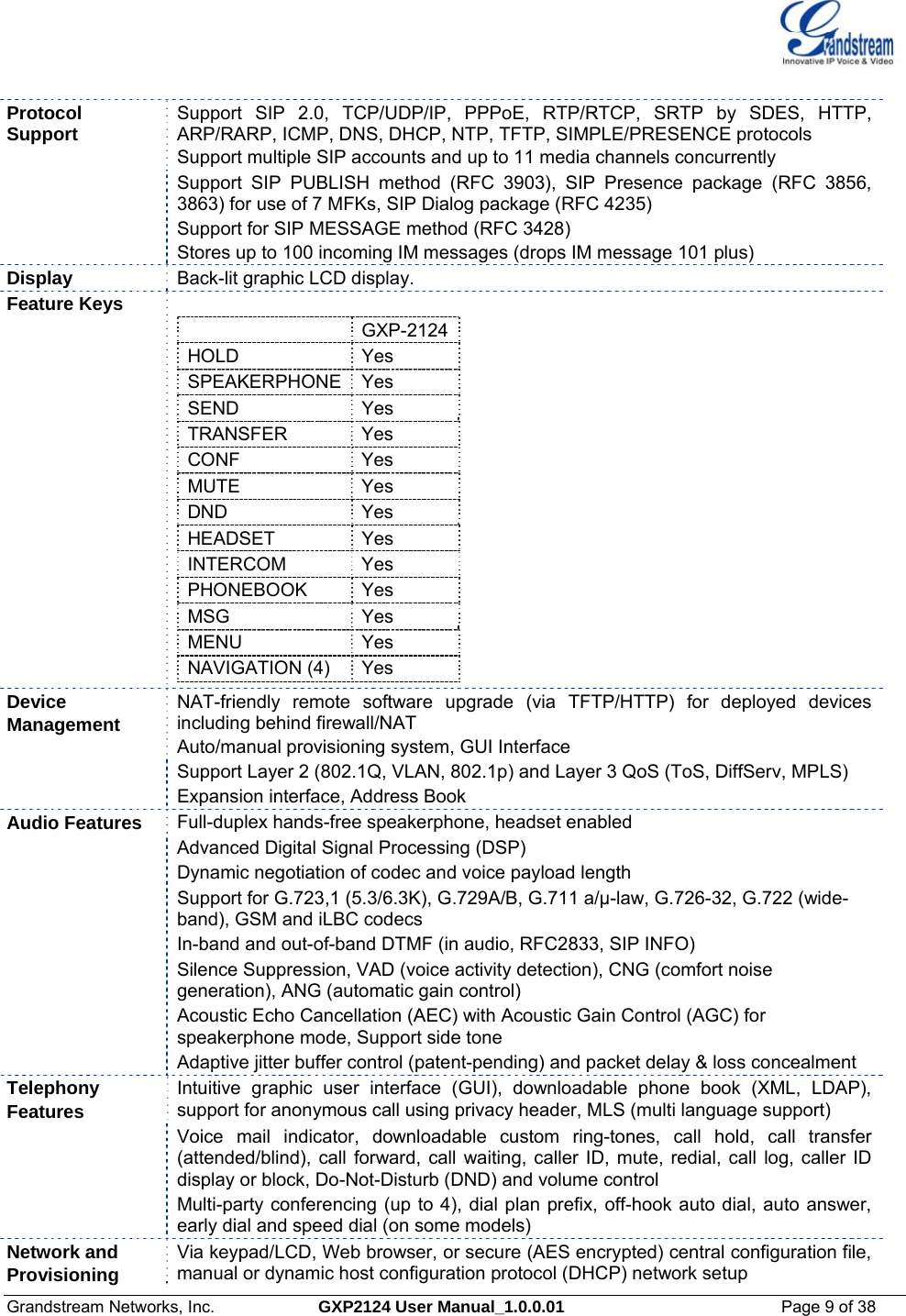
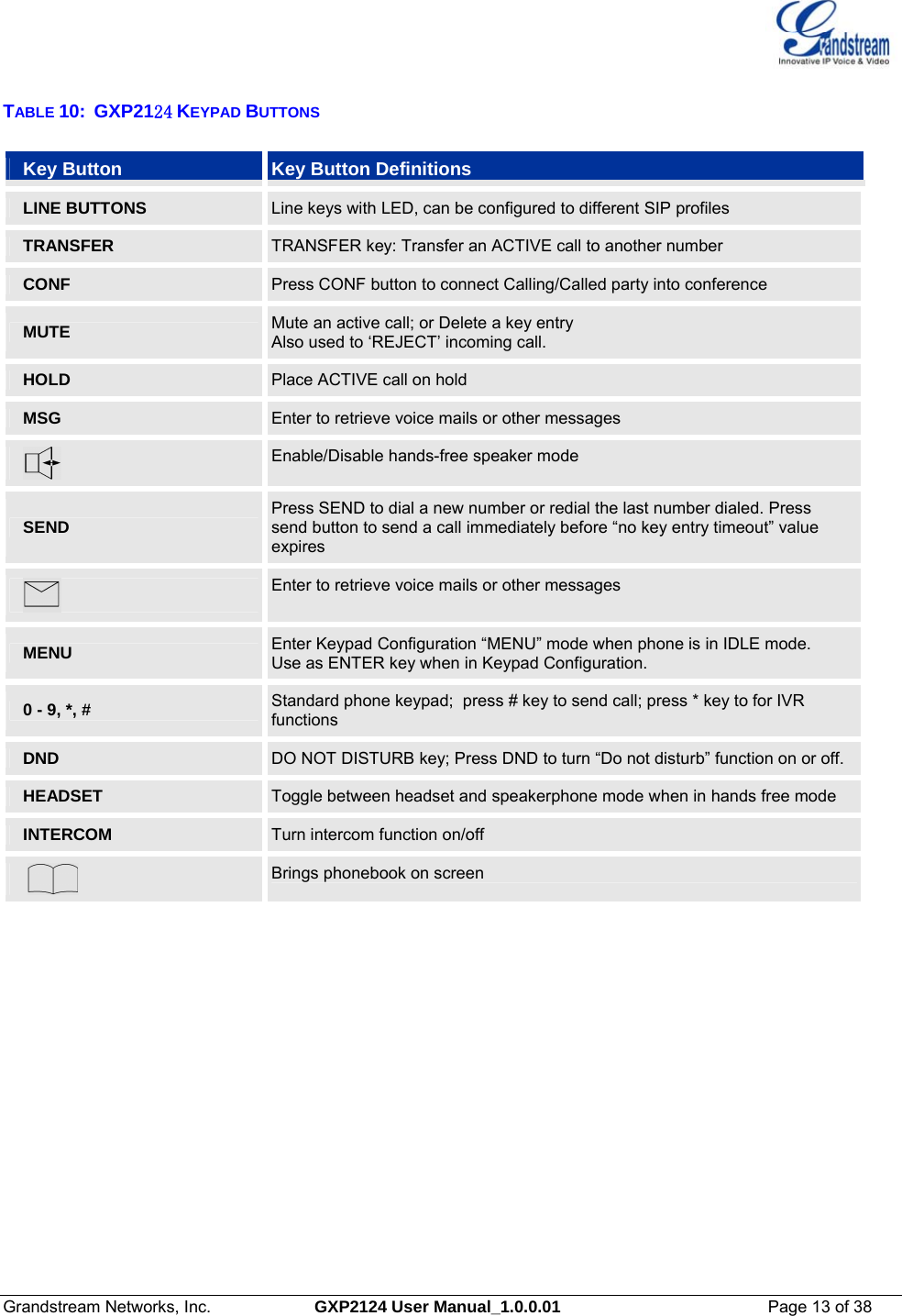
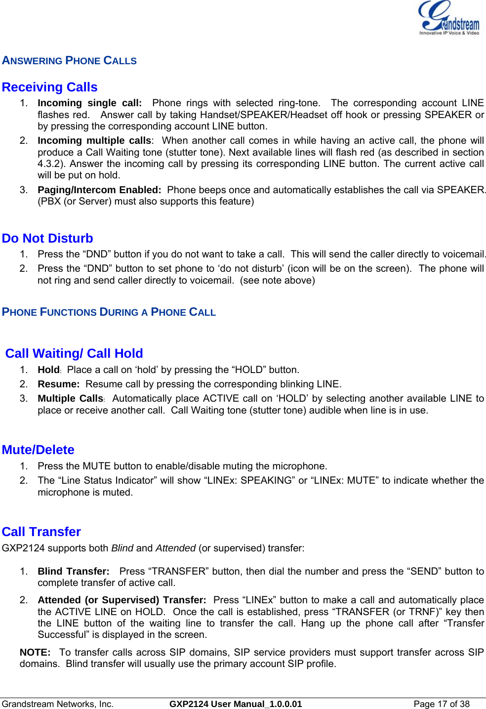
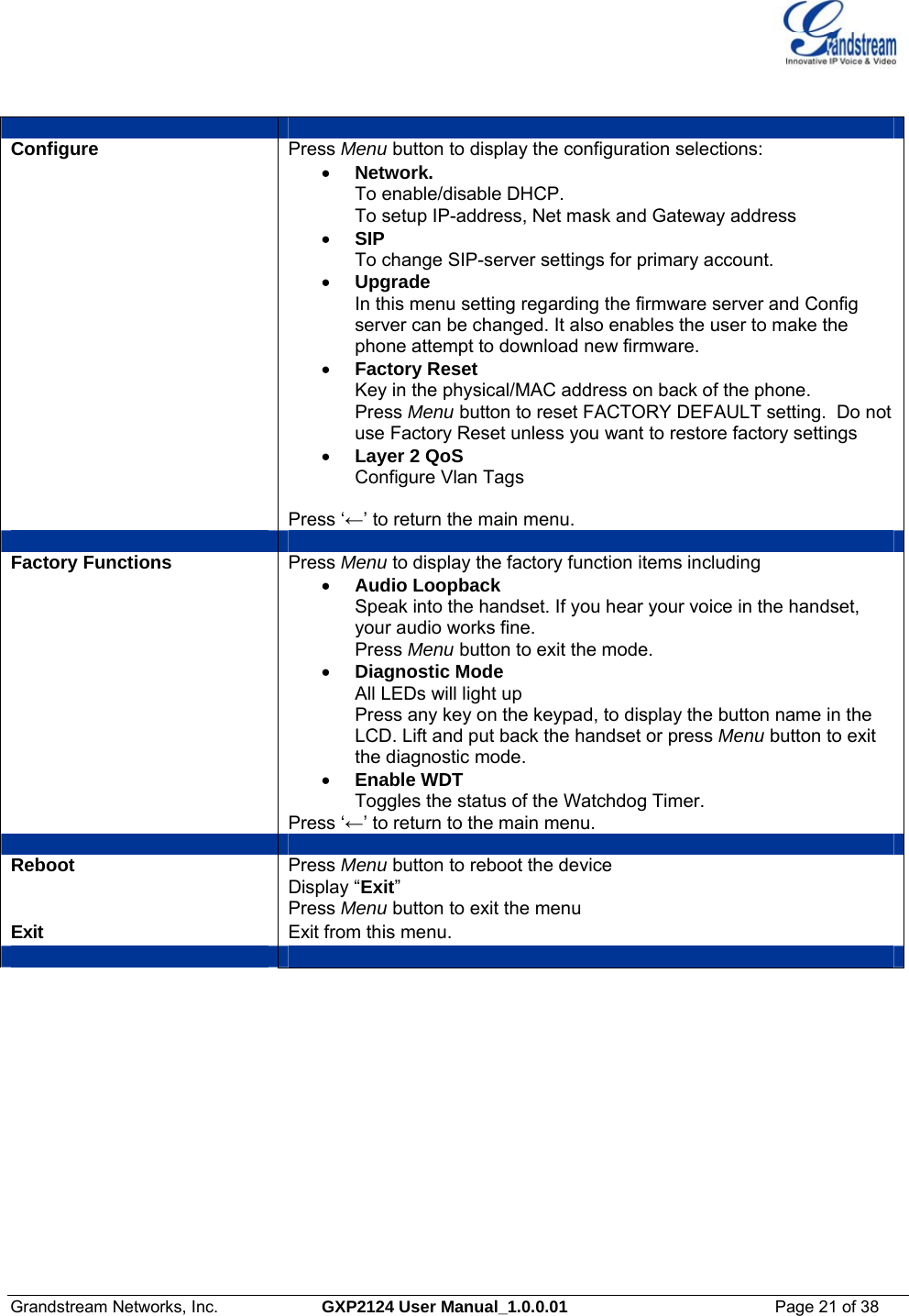
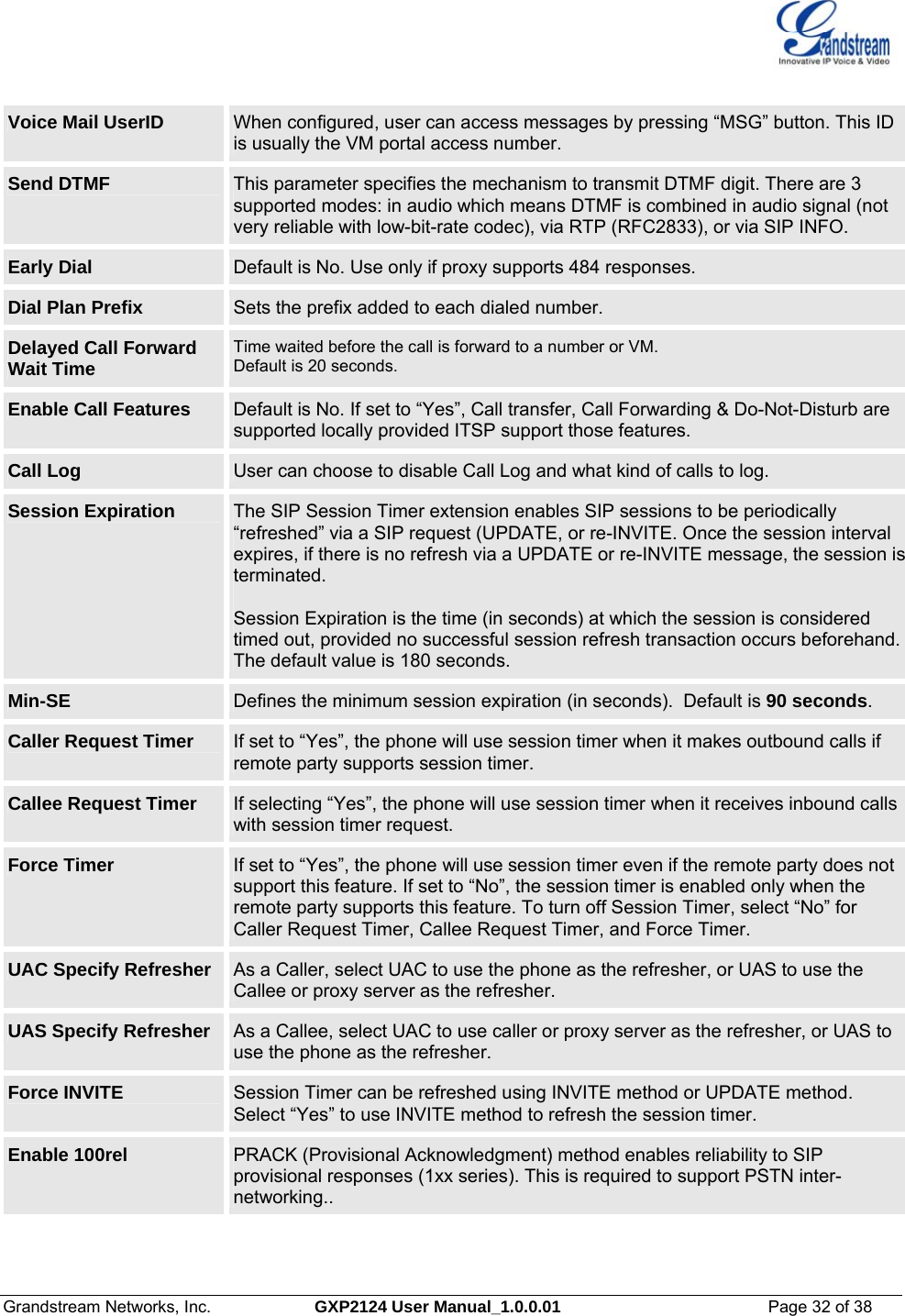
![Grandstream Networks, Inc. GXP2124 User Manual_1.0.0.01 Page 28 of 38 Allow DHCP Option 66 to override server Default is Yes. This allows device gets provisioned automatically. Authenticate Conf File Default is “No”. If set to “Yes”, configuration file would be authenticated before acceptance. End user should use default setting. Automatic Upgrade This function is used by ITSP. End user should NOT touch these parameters. Default is No. Choose “Yes” to enable automatic HTTP upgrade and provisioning. In “Check for upgrade every” field, enter the number of minutes to check the HTTP server for firmware upgrade or configuration changes. When set to “No”, the phone will only perform HTTP upgrade and configuration check once at boot up. LDAP Directory IP address or domain name of LDAP script server Phonebook XML Enable the XML phonebook via TFTP or HTTP. Define XML server path and download interval. When the user downloads the XML phone the manually entered or edited entries will not be deleted unless this option is selected to Yes. Idle Screen XML Download Enable XML Idle Screen download via TFTP or HTTP. Define XML server path. XML Application Enter server path for XML application. This option applies to GXP-2124 only. Offhook Auto Dial To configure a User ID/extension to dial automatically when the phone is taken offhook. DTMF Payload Type This parameter sets the payload type for DTMF using RFC2833. Default is 101. Syslog Server The IP address or URL of System log server. This feature is especially useful for ITSPs.Syslog Level Select the ATA to report the log level. Default is NONE. The level is one of DEBUG, INFO, WARNING or ERROR. Syslog messages are sent based on the following events:• product model/version on boot up (INFO level) • NAT related info (INFO level) • sent or received SIP message (DEBUG level) • SIP message summary (INFO level) • inbound and outbound calls (INFO level) • registration status change (INFO level) • negotiated codec (INFO level) • Ethernet link up (INFO level) • SLIC chip exception (WARNING and ERROR levels) • memory exception (ERROR level) The Syslog uses USER facility. In addition to standard Syslog payload, it contains the following components: GS_LOG: [device MAC address][error code] error message For example: May 19 02:40:38 192.168.1.14 GS_LOG: [00:0b:82:00:a1:be][000]. Ethernet link is up.](https://usermanual.wiki/Grandstream-Networks/GXP2124/User-Guide-1639064-Page-28.png)
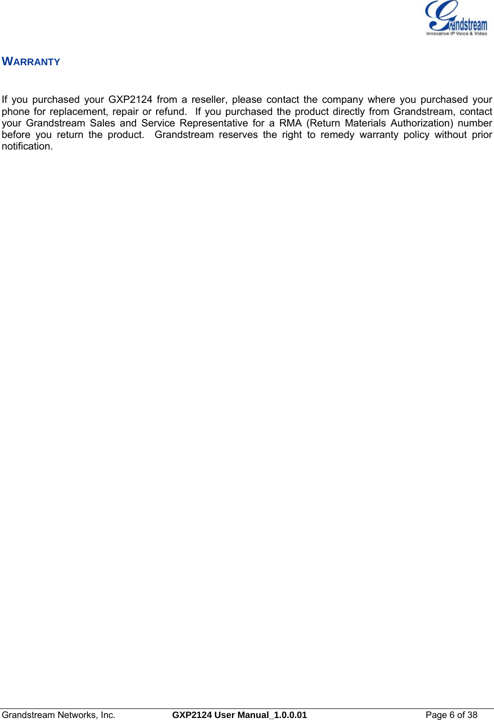
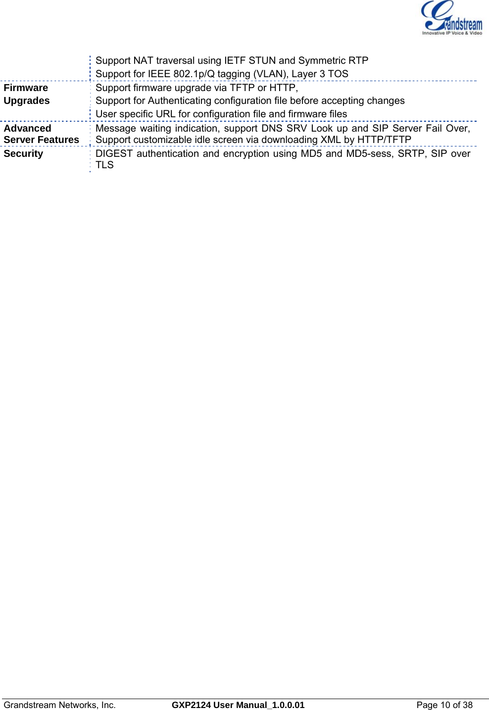
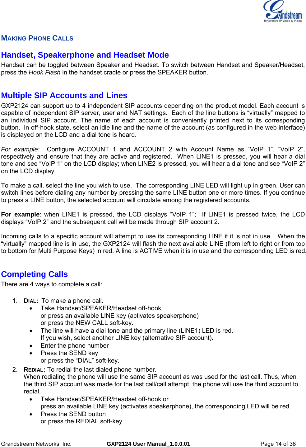
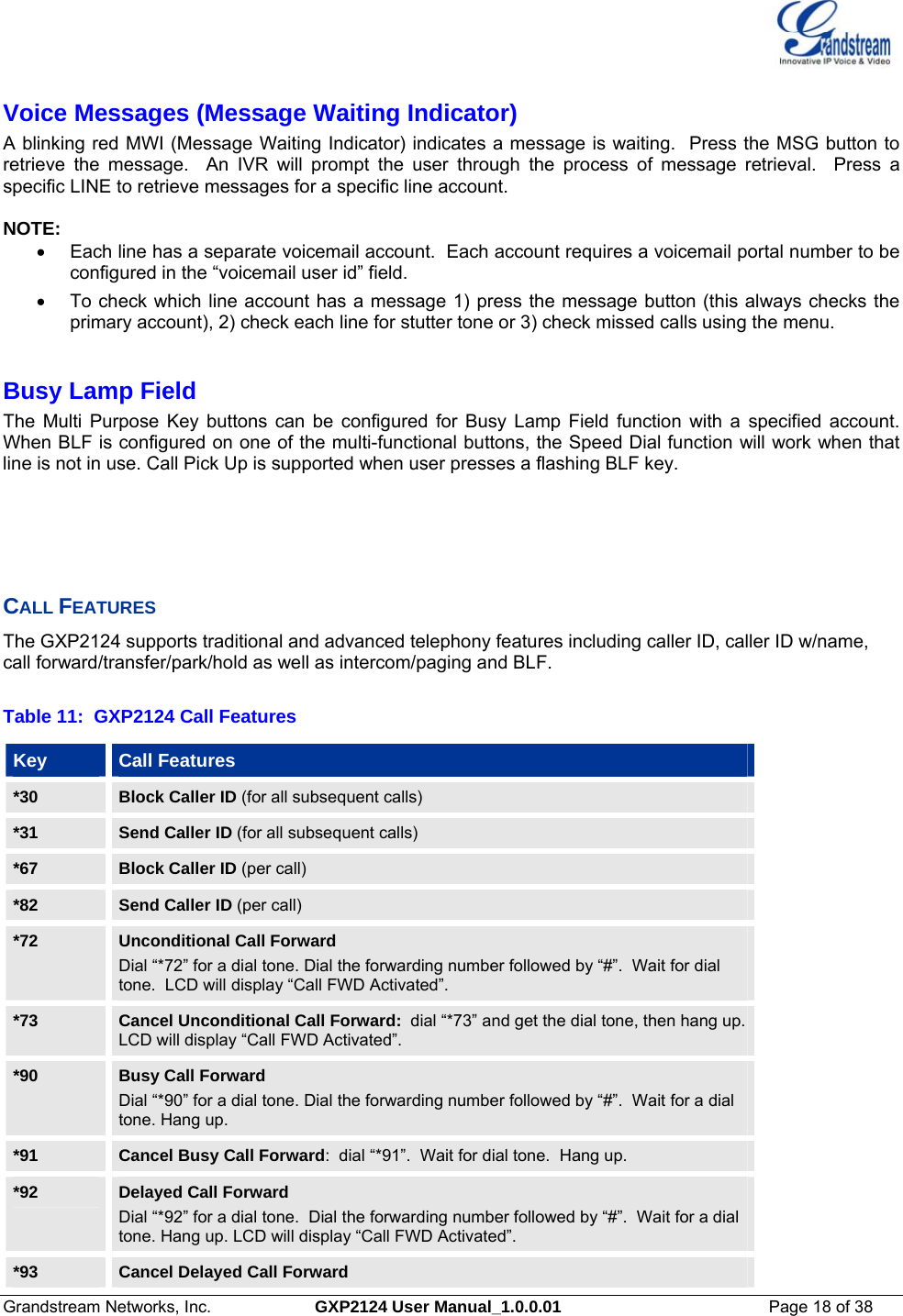
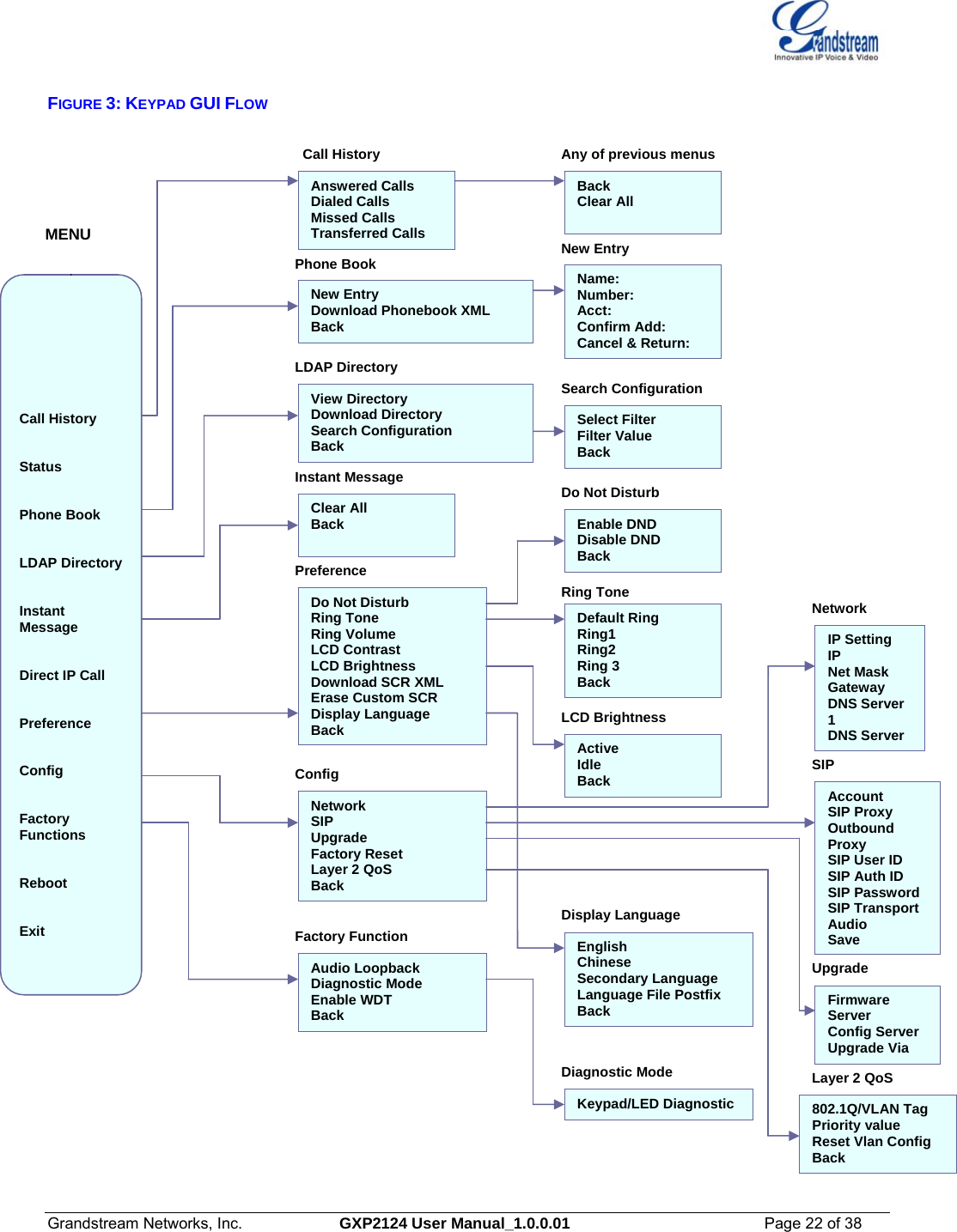
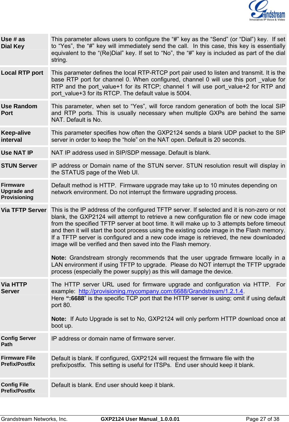
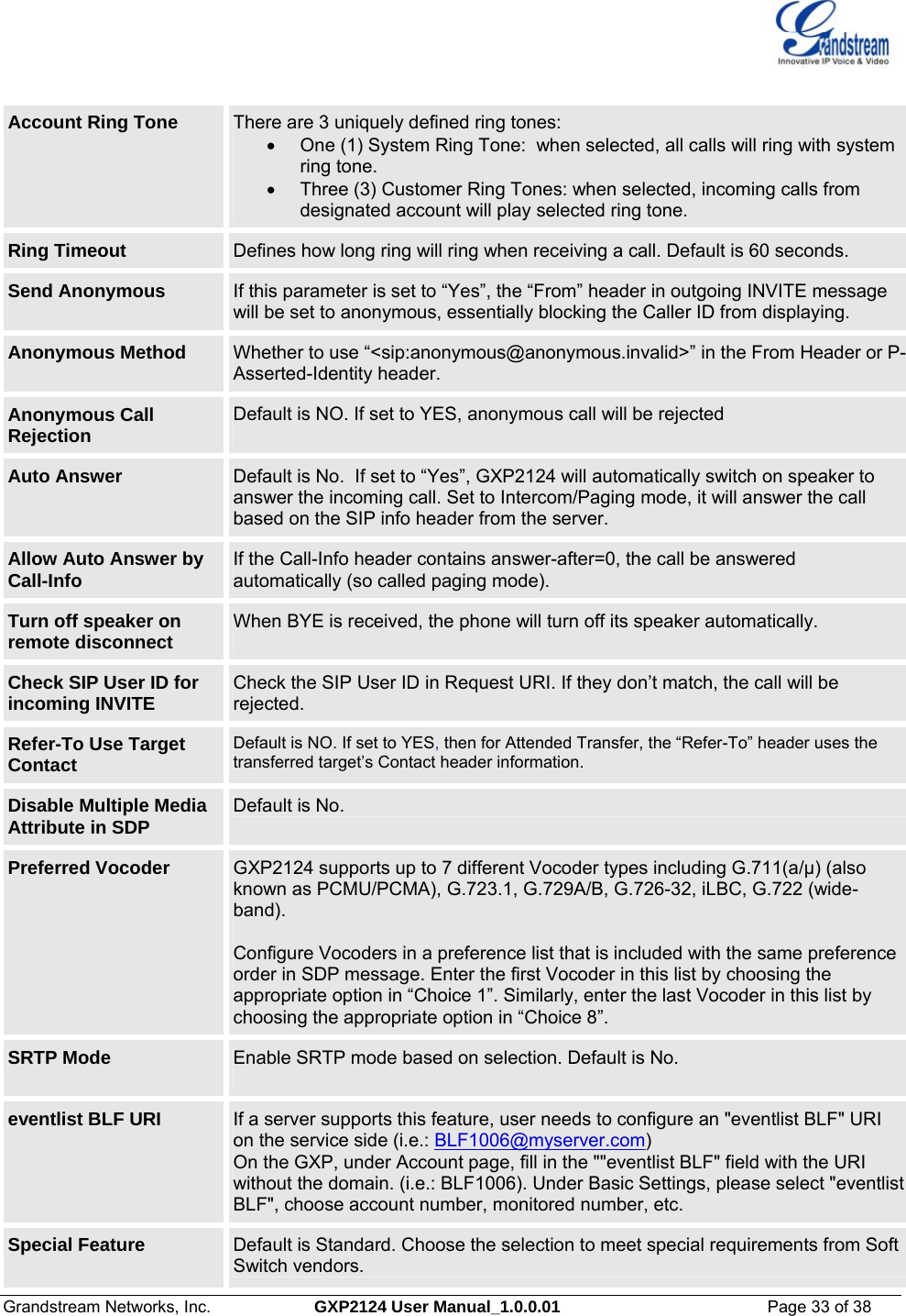
![Grandstream Networks, Inc. GXP2124 User Manual_1.0.0.01 Page 29 of 38 NTP server This parameter defines the URI or IP address of the NTP (Network Time Protocol) serve. It is used to display the current date/time. Distinctive Ring Tone Caller ID must be configured. Select a Distinctive Ring Tone 1 through 3 for a particular Caller ID. The GXP2124 will ONLY use selected ring tones for particular Caller IDs. For all other calls, the GXP2124 will use System Ring Tone. When selected and no Caller ID is configured, the selected ring tone will be used for all incoming calls. System Ring Tone System ring tone. Default is North American standard. Adjust system ring tone frequencies and cadences based on local telecom standard. Call Progress Tones Using these settings, users can configure ring or tone frequencies based on parameters from local telecom. By default, they are set to North American standard. Frequencies should be configured with known values to avoid uncomfortable high pitch sounds. Syntax: f1=val,f2=val[,c=on1/off1[-on2/off2[-on3/off3]]]; (Frequencies are in Hz and cadence on and off are in 10ms) ON is the period of ringing (“On time” in ‘ms’) while OFF is the period of silence. In order to set a continuous ring, OFF should be zero. Otherwise it will ring ON ms and a pause of OFF ms and then repeat the pattern. Up to three cadences are supported. Intercom User ID: This field is used to configure the Intercom key in the phone. If the phone is working with a GS GXE502X IP-PBX it can be configured in the following manner: • To page an extension : [intercom feature code]+[*]+[extension number] • To page a group : [paging group feature code]+[*]+[group extension] Disable Call Waiting Default is No. If set to Yes, the call waiting feature will be disabled. Disable Call Waiting Tone Default is No. If set to Yes, the call waiting tone will be disabled. Disable Direct IP Calls Default is No. If set to Yes, direct IP calls will be disabled Use Quick IP Call Mode Dial an IP address under the same LAN/VPN segment by entering the last octet in the IP address. In the Advanced Settings page there is an option “Use Quick IP-call mode”. Default setting is No. When set to YES, and #XXX is dialed, where X is 0-9 and XXX <=255, phone will make direct IP call to aaa.bbb.ccc.XXX where aaa.bbb.ccc comes from the local IP address REGARDLESS of subnet mask. #XX or #X are also valid so leading 0 is not required (but OK). See Quick IP Call Modefor details. Disable Conference Default is No. If set to Yes, conference will be disabled. Lock keypad update If set to “Yes”, the configuration changes via keypad are disabled.](https://usermanual.wiki/Grandstream-Networks/GXP2124/User-Guide-1639064-Page-29.png)
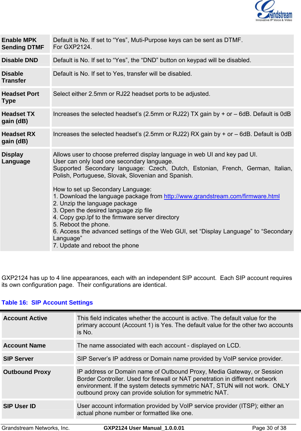
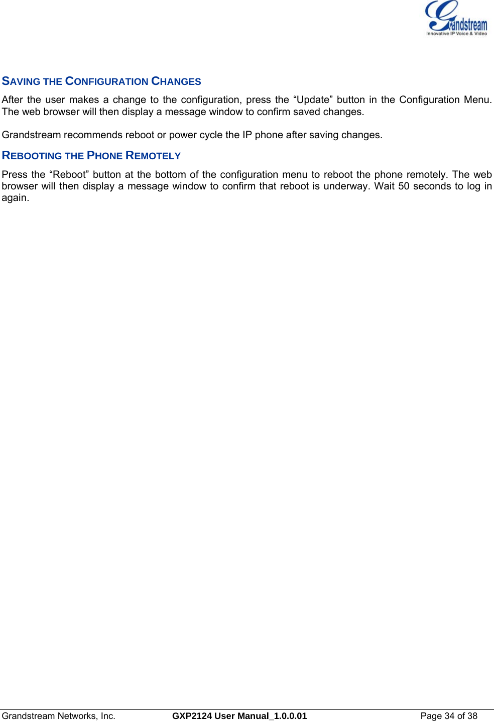
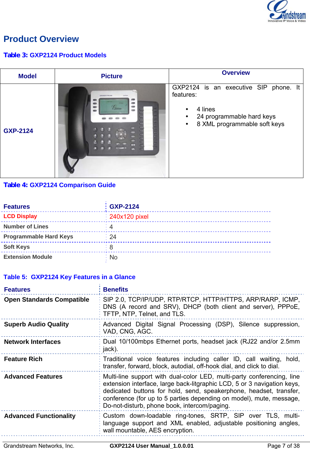
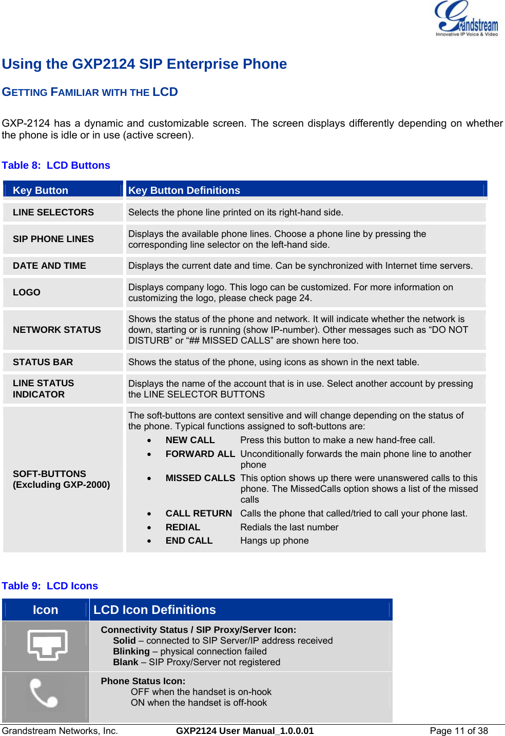
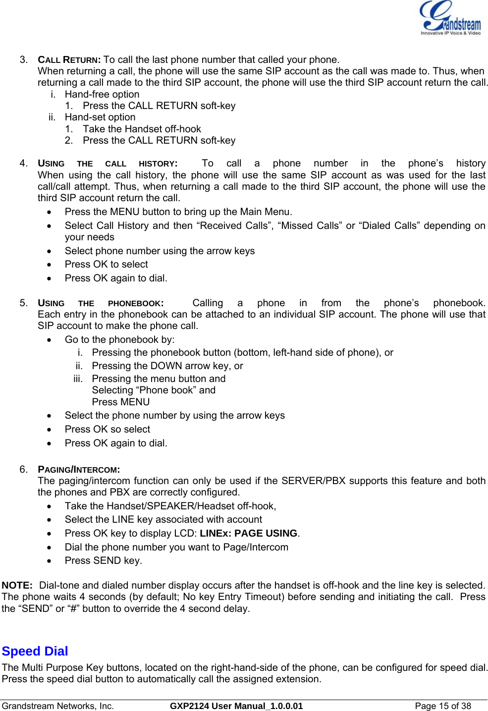
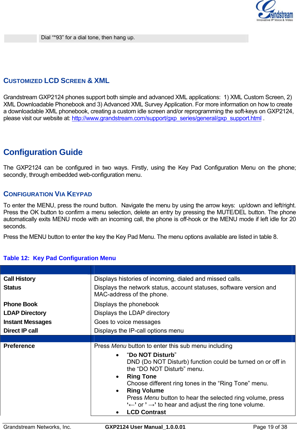
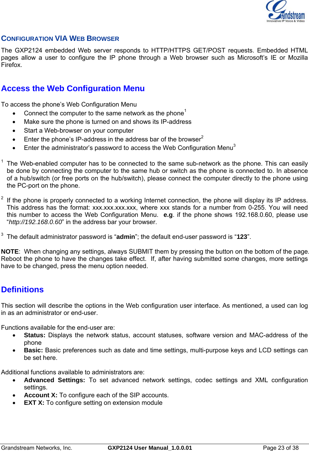
![Grandstream Networks, Inc. GXP2124 User Manual_1.0.0.01 Page 36 of 38 Instructions for local TFTP Upgrade: 1. Unzip the file and put all of them under the root directory of the TFTP server. 2. The PC running the TFTP server and the GXP2124 should be in the same LAN segment. 3. Go to File -> Configure -> Security to change the TFTP server's default setting from "Receive Only" to "Transmit Only" for the firmware upgrade. 4. Start the TFTP server, in the phone’s web configuration page 5. Configure the Firmware Server Path with the IP address of the PC 6. Update the change and reboot the unit User can also choose to download the free HTTP server from http://httpd.apache.org/ or use Microsoft IIS web server. NOTE: • When GXP2124 phone boots up, it will send TFTP or HTTP request to download configuration file “cfg000b82xxxxxx”, where “000b82xxxxxx” is the MAC address of the GXP2124 phone. This file is for provisioning purpose. For normal TFTP or HTTP firmware upgrades, the following error messages in a TFTP or HTTP server log can be ignored: “TFTP Error from [IP ADRESS] requesting cfg000b82023dd4 : File does not exist. Configuration File Download” CONFIGURATION FILE DOWNLOAD The GXP2124 can be configured via Web Interface as well as via Configuration File through TFTP or HTTP. “Config Server Path” is the TFTP or HTTP server path for the configuration file. It needs to be set to a valid URL, either in FQDN or IP address format. A configuration parameter is associated with each particular field in the web configuration page. A parameter consists of a Capital letter P and 2 to 4 digit numeric numbers. i.e., P2 is associated with “Admin Password” in the ADVANCED SETTINGS page. For a detailed parameter list, please refer to the corresponding configuration template of the firmware. Once the GXP2124 boots up (or re-booted), it will request a configuration file named “cfgxxxxxxxxxxxx”, where “xxxxxxxxxxxx” is the MAC address of the device, i.e., “cfg000b820102ab”. The configuration file name should be in lower cases. Managing Firmware and Configuration File Download When “Automatic Upgrade” is set to “Yes”, a Service Provider can use P193 (Auto Check Interval, in minutes, default and minimum is 60 minutes) to have the devices periodically check for upgrades at pre-scheduled time intervals. By defining different intervals in P193 for different devices, a Server Provider can manage and reduce the Firmware or Provisioning Server load at any given time.](https://usermanual.wiki/Grandstream-Networks/GXP2124/User-Guide-1639064-Page-36.png)