Grandstream Networks GXW410X VOIP GATEWAY User Manual
Grandstream Networks, Inc. VOIP GATEWAY
Contents
- 1. Users Manual
- 2. User Manual
Users Manual


TABLE OF CONTENTS
GXW410X USER MANUAL
WELCOME .................................................................................................................................................5
Gateway GXW410x Overview................................................................................................................................5
Safety Compliances.................................................................................................................................................5
Warranty.................................................................................................................................................................5
PACKAGING ..............................................................................................................................................6
CONNECTING THE GXW410X .........................................................................................................................................6
APPLICATION DESCRIPTION...................................................................................................................8
Functional Diagram of IP-PBX & GXW410x........................................................................................................8
GXW400x & GXW410x Scenario/Toll- Free Calling Between Locations.............................................................9
FXS and FXO Gateway Configuration Example..................................................................................................10
FEATURES...............................................................................................................................................10
SOFTWARE FEATURES OVERVIEW.....................................................................................................................................10
HARDWARE SPECIFICATION.............................................................................................................................................11
CONFIGURATION GUIDE........................................................................................................................13
CONFIGURATION WITH WEB BROWSER.............................................................................................................................13
Accessing the Web Configuration Menu...............................................................................................................13
End-user Configuration........................................................................................................................................13
ADVANCED USER SETTINGS............................................................................................................................................17
Advanced User Configuration .............................................................................................................................17
CONFIGURING THE FXO CHANNELS ................................................................................................................................20
PROFILES......................................................................................................................................................................26
Saving the Configuration Changes.......................................................................................................................28
Rebooting from Remote........................................................................................................................................28
VIDEO SURVEILLANCE...........................................................................................................................29
VIDEO SURVEILLANCE PROCEDURES.................................................................................................................................29
FIRMWARE UPGRADE............................................................................................................................31
UPGRADE THROUGH HTTP............................................................................................................................................31
UPGRADE THROUGH TFTP.............................................................................................................................................31
Download TFTP Server........................................................................................................................................32
RESTORE FACTORY DEFAULT SETTING.............................................................................................33
EXAMPLES OF GXW410X CONFIGURATIONS......................................................................................34
GXW410x User Manual www.grandstream.com
Firmware Version 1.3.1.6 support@grandstream.com

TABLE OF FIGURES
GXW410X USER MANUAL
FIGURE 1: DIAGRAM OF GXW410X BACK PANEL................................................................................6
FIGURE 2: DIAGRAM OF GXW410X DISPLAY PANEL..........................................................................7
FIGURE 7: SCREEN-SHOT OF VIDEO SURVEILLANCE* ....................................................................30
APPLICATION ONE: GXW CONNECTED WITH AN IP-PBX OR SIP SERVER....................................34
APPLICATION TWO: GXW TO EXTEND A TRADITIONAL PBX SCENARIO.......................................34
APPLICATION THREE: GXW CONNECTED WITH AN IP-PBX OR SIP SERVER AND VIDEO
SURVEILLANCE.......................................................................................................................................35
APPLICATION FOUR: USING A GXW FOR PURE IP- IP COMMUNICATION CONFIGURATION.......36
INDEX OF TABLES
GXW410X USER MANUAL
TABLE 1: DEFINITIONS OF THE GXW CONNECTORS..........................................................................6
TABLE 2: DEFINITIONS OF THE GXW DISPLAY PANEL.......................................................................7
TABLE 4: HARDWARE SPECIFICATION OF GXW410X ......................................................................11
TABLE 3: GXW410X SOFTWARE FEATURES......................................................................................12
TABLE 6: WEB LOG-IN DEFINITIONS (BASIC SETTINGS PAGE).......................................................14
TABLE 7: STATUS PAGE DEFINITIONS...............................................................................................15
TABLE 8: ADVANCED CONFIGURATION PAGE DEFINITIONS..........................................................17
TABLE 9: FXO LINES CONFIGURATION DEFINITIONS.......................................................................20
TABLE 10: FXO LINE TEST TAB DEFINITIONS.....................................................................................23
TABLE 11: CHANNELS PAGE DEFINITIONS........................................................................................24
TABLE 12: CHANNELS PAGE DEFINITIONS........................................................................................26
TABLE 13: PROFILE PAGE DEFINITIONS............................................................................................26
GXW410x User Manual www.grandstream.com
Firmware Version 1.3.1.6 support@grandstream.com

GUI INTERFACES
GXW410X USER MANUAL
http://www.grandstream.com/support/gxw_series/gxw410x/documents/gxw410x_gui.zip
1. SCREENSHOT OF ADVANCED SETTINGS CONFIGURATION PAGE
2. SCREENSHOT OF BASIC SETTINGS CONFIGURATION PAGE
3. SCREENSHOT OF CHANNELS CONFIGURATION PAGE
4. SCREENSHOT OF FXO LINES CONFIGURATION PAGE
5. SCREENSHOT OF PROFILE 1 CONFIGURATION PAGE
6. SCREENSHOT OF STATUS CONFIGURATION PAGE
GXW410x User Manual www.grandstream.com
Firmware Version 1.3.1.6 support@grandstream.com

WELCOME
Thank you for purchasing the Grandstream GXW410x IP Analog FXO Gateway. The GXW410x is a cost
effective, easy to use and easy to configure IP communications solution for any business. The GXW410x
gateway supports popular voice codecs and is designed for full SIP compatibility and interoperability with
party SIP providers, thus enabling you to fully leverage the benefits of VoIP technology, integrate a
traditional phone system into a VoIP network, and efficiently manage communication costs.
This manual will help you learn how to operate and manage your GXW FXO Analog IP Gateway and
make the best use of its many upgraded features including simple and quick installation, multi-party
conferencing, etc. This IP Analog Gateway is very easy to manage and scalable, specifically designed to
be an easy to use and affordable VoIP solution for the small – medium business or enterprise. Enable the
video surveillance port to give you peace of mind while you are away from your business.
GATEWAY GXW410X OVERVIEW
The GXW410x offers an easy to manage, feature-rich IP communications solution for any small business
or businesses with virtual and/or branch locations who want to leverage their broadband network and/or
add new IP Technology to their current phone system. The Grandstream enterprise analog VoIP Gateway
GXW410x series converts SIP/RTP IP calls to traditional PSTN calls and vice versa. There are two
models - the GXW4104 and GXW4108, which feature 4 or 8 FXO ports respectively. The installation is
the same for either model.
SAFETY COMPLIANCES
The GXW410x is compliant with various safety standards including FCC/CE. Its power adapter is
compliant with UL standard. Warning: use only the power adapter included in the GXW410x package.
Using an alternative power adapter may permanently damage the unit.
WARRANTY
Grandstream has a reseller agreement with our reseller customer. End-users should contact the
company from whom you purchased the product for replacement, repair or refund.
If you purchased the product directly from Grandstream, contact your Grandstream Sales and Service
Representative for a RMA (Return Materials Authorization) number. Grandstream reserves the right to
remedy warranty policy without prior notification.
Caution: Changes or modifications to this product not expressly approved by Grandstream, or operation
of this product in any way other than as detailed by this User Manual, could void your manufacturer
warranty.
•This document contains links to Grandstream GUI Interfaces. Please download the GUI
examples http://www.grandstream.com/support/gxw_series/gxw410x/documents/gxw410x_gui.zip for
your reference.
•This document is subject to change without notice. The latest electronic version of this user
manual is available on our website:
http://www.grandstream.com/support/gxw_series/gxw410x/documents/gxw410x_usermanual_english
.pdf
Reproduction or transmittal of the entire or any part, in any form or by any means, electronic or print, for
any purpose without the express written permission of Grandstream Networks, Inc. is not permitted.
PACKAGING
Unpack and check all accessories. Equipment included in the package:
1) One GXW410x Unit
2) One universal power adapter
3) One Ethernet cable
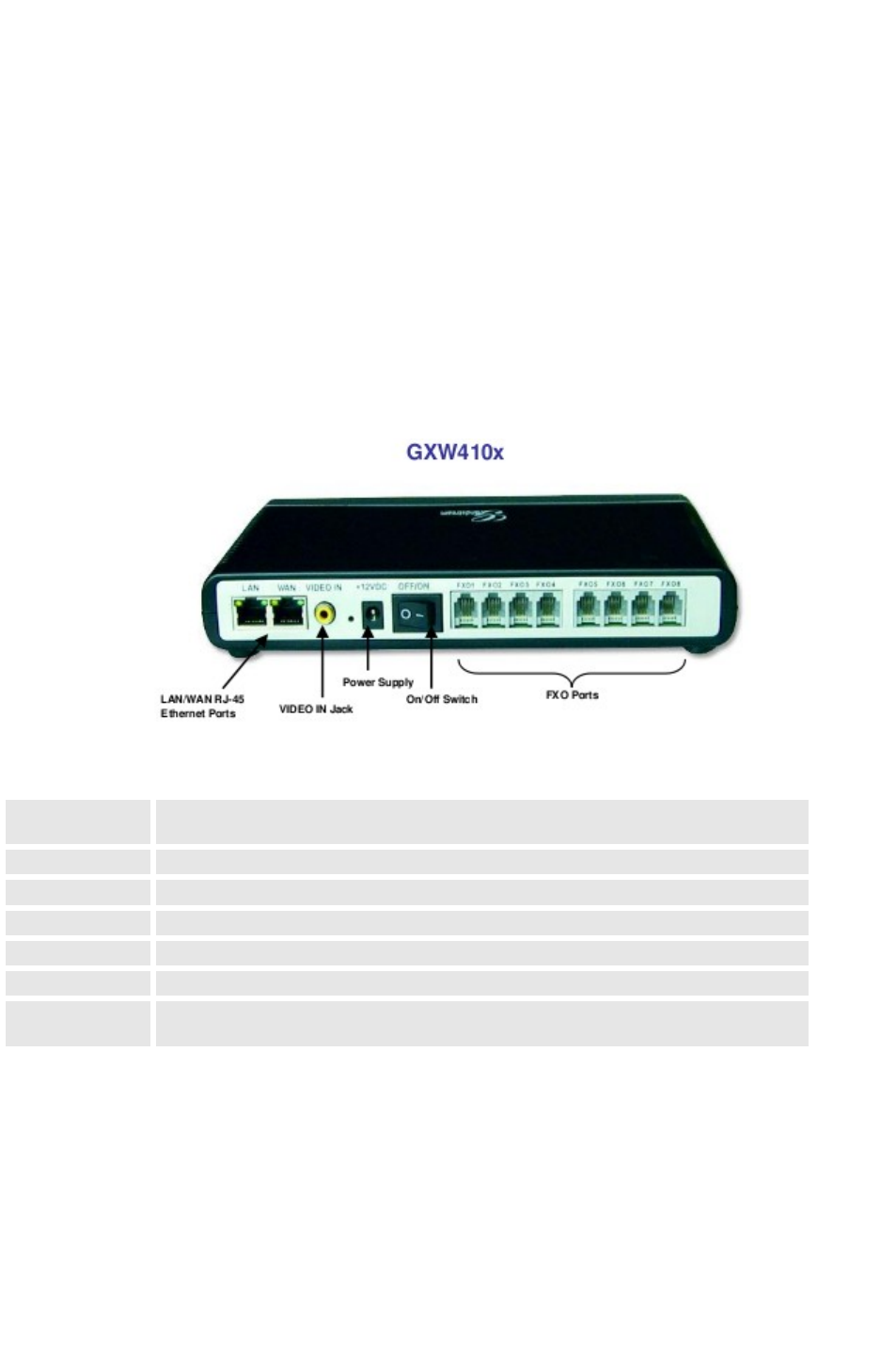
CONNECTING THE GXW410X
FIGURE 1: DIAGRAM OF GXW410X BACK PANEL
TABLE 1: DEFINITIONS OF THE GXW CONNECTORS
LAN (or PC) Connect your PC to this port. It will then be assigned an IP address from your
Router/DHCP Server. The GXW410x acts as a switch only.
WAN Connect to the internal LAN network or Public Internet.
VIDEO IN Connection for Analog based Video Surveillance Camera (RCA)
RESET Factory Reset button. Press for 7 seconds to reset factory default settings.
POWER IN Power adapter connection
OFF/ON Off/On switch
FXO1 - FXO8 FXO ports to be connected to physical PSTN lines from a traditional PSTN PBX or
PSTN Central Office.

FIGURE 2: DIAGRAM OF GXW410X DISPLAY PANEL
TABLE 2: DEFINITIONS OF THE GXW DISPLAY PANEL
Power LED Indicates Power. Remains ON when Power is connected and unit is turned ON.
Ready LED Remains ON after boot-up.
LAN LED Indicates LAN (or WAN) port activity
PC LED Indicates PC (or LAN) port activity
Video LED Remains solid green on boot-up. If Video IN terminal is connected, indicates
video activity.
LEDs 1 - 8 Indicate status of the respective FXO Ports on the back panel
Busy - ON
Available - OFF
NOTE: All LEDs display green when ON. The Ready light will only be ON when the network interface is
ready and the Web User Interface is accessible.
During a firmware upgrade or configuration download the following LED pattern will be observed:
Power, Ready, Video and WAN LEDs will be ON. The FXO port LED will keep flashing during download
and then stay OFF while the new files are written. The entire process may take between 20 to 30
minutes. The firmware upgrade is complete when you can login into the web configuration pages.
APPLICATION DESCRIPTION
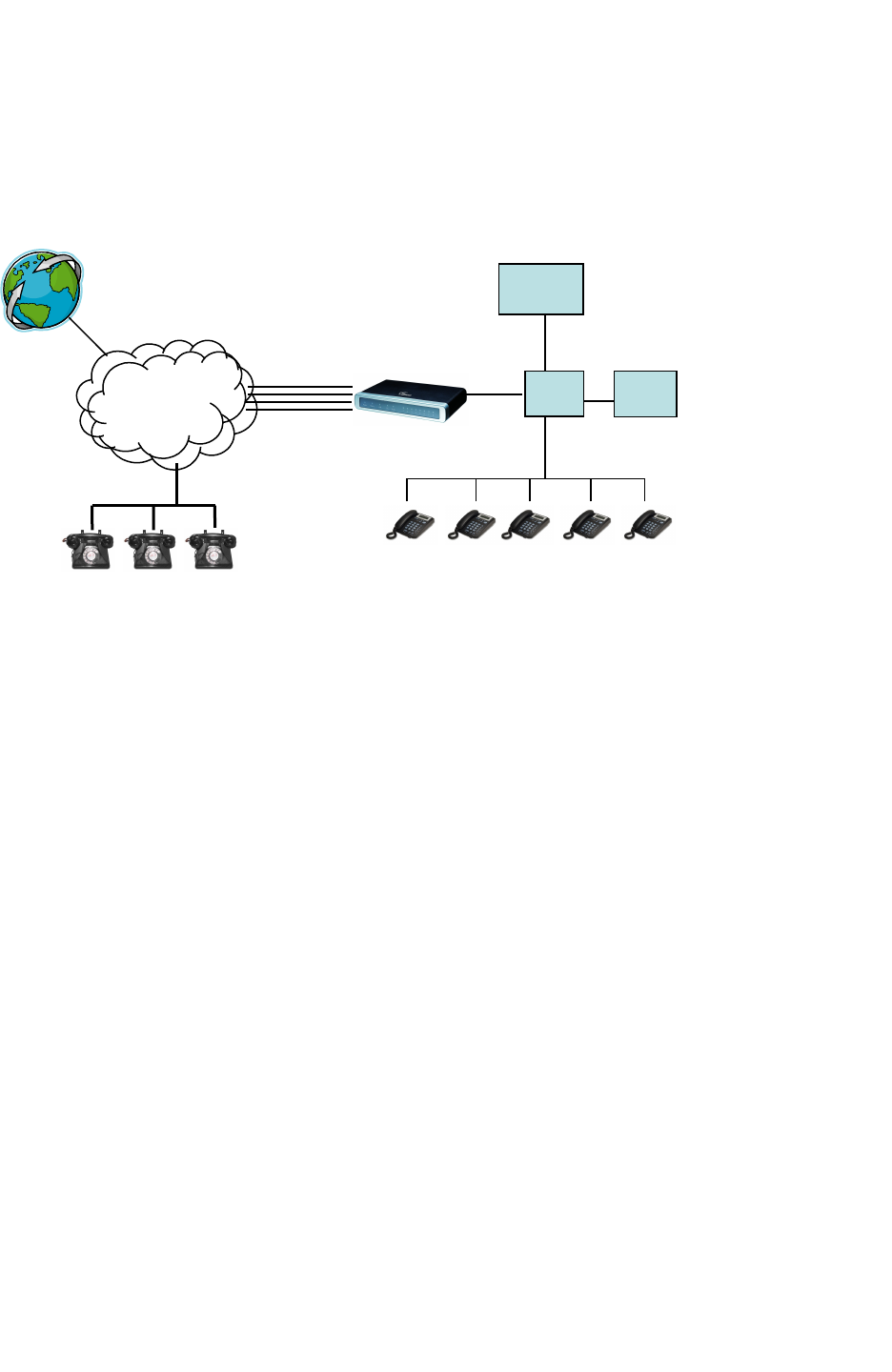
A. IP PBX / SIP Server with GXW410x
A SIP proxy server such as Asterisk or a SIP registrar server can be deployed with the GXW410x series
gateway. In this environment, the SIP server handles SIP registration and call control and the GXW410x
processes media conversion between IP and PSTN calls.
There are 2 ways to configure GXW410x when using it with a SIP Server:
1. With SIP accounts configured on Channels page. In this case, the GXW410x gateway acts as
an endpoint requesting registration from the SIP Server. Under the Channels page you will need
to fill in the information like SIP User ID, Password, etc. Now, when calls are made from an IP
phone, the call will be routed to the SIP Server which will forward it to one of the SIP accounts on
the GXW410x, which will then forward it to the PSTN line.
2. Without SIP accounts. In this case, you simply have to configure the SIP Server to perform
forwarding of the SIP INVITE message with the FXO destination number to the gateway’s IP
Address. The GXW410x gateway will receive the digits and immediately forward them on the
FXO lines to the destination PSTN. Most of the configuration on the Gateway for this case will
remain default, except Stage Method needs to be set to 1, and SIP Server IP Address/DNS name
has to be filled.
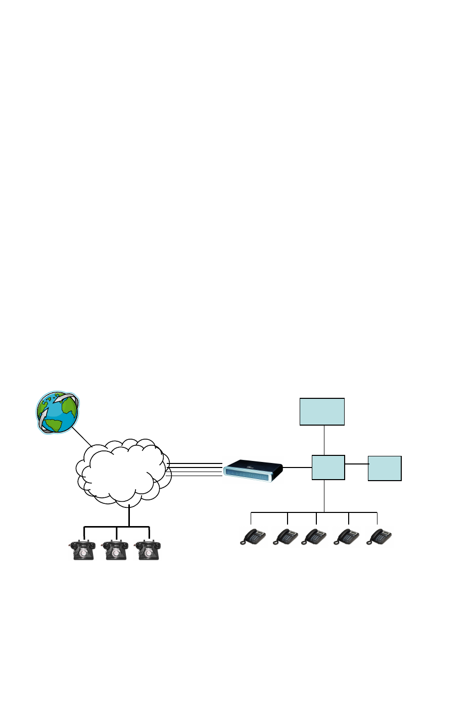
FUNCTIONAL DIAGRAM OF IP-PBX & GXW410X
For incoming calls from the PSTN analog endpoints to the GXW410x gateway, the device will auto
forward each call to a configured IP extension. The SIP Server can then route the call based on its own
configuration or IVR system.
PSTN
PSTN
Cloud
Cloud
Anywhere in the
world
GXW-
410x
4 or 8
Ports
FXO
Lines
PSTN Analog
endpoints
Grandstream IP
Phones
IPPBX or
SIP
Server
IP/LAN IP/WA
N
B. FXS Gateway with GXW410x [No SIP Server required]
Alternatively, the GXW410x gateway can be used without a SIP Server. It can be used in conjunction with
an FXS Gateway (Ex. GXW400x) and calls can still be originated from the IP network and terminated on
the PSTN network and vice versa. All you need to make sure is that both gateways are able to locate
each other (i.e. they should be on the same LAN or have public IP addresses).
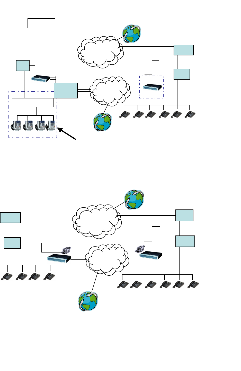
GXW400X & GXW410X SCENARIO/TOLL- FREE CALLING BETWEEN LOCATIONS
If you setup resembles the one in this diagram, you need to configure the SIP Server field to be the IP
address of the other gateway (i.e. configure the IP address of GXW400x gateway to be the SIP Server for
the GXW410x gateway and vice versa). Please be sure you set SIP Registration to No.
EXPECTED CALL FLOW: An analog Phone (connected to the GXW400x gateway) picks up and dials the
destination PSTN number. The call gets routed to the GXW410x gateway which dials out the digit string
onto the FXO Lines, thus reaching the destination PSTN endpoint. On the reverse, incoming calls from
the PSTN endpoints connected to the GXW410x gateway will be routed automatically to the analog
endpoints connected to the GXW400x gateway.
Branch A -
Boston, MA
4 employees
Branch B –
Denver, CO
4 employees
Internet
Internet
Cloud
Cloud
GXW-400x
GXW-410x
Analo
g
Phon
es
PSTN
PSTN
Cloud
Cloud
FX0
Lines

FXS AND FXO GATEWAY CONFIGURATION EXAMPLE
GXW400X GATEWAY GXW410X GATEWAY
Profile 1
SIP Server - Set it to IP Address of
GXW410x
SIP Registration - No
Outgoing Call without Registration - Yes
NAT traversal – No
Advanced Settings
STUN Server - Blank
Use Random Port - No
Advanced Settings
STUN Server - Blank
FXO lines
Wait for Dial Tone - Y or N (whichever works for your
PSTN Service Provider)
Stage Method - 1
Unconditional Call Forward to VOIP:
ch1-8:444; @ch1-8:p1; ch1-8:5060++;
Channels
1-8 5060 Profile 1
Local SIP Listen port (For VOIP to PSTN calls) - 5060++
Profile 1
SIP Server - Set it to IP Address of GXW400x
SIP Registration - No
NAT traversal - No
For more information regarding this setup, email Grandstream technical support at support@grandstream.com
or visit our User and Developer forum at forums.grandstream.com

FEATURES
The GXW410x is a next generation IP voice and video gateway that features full interoperability with
leading IP-PBXs, Soft-switches and SIP platforms. The GXW410x series gateways offer superb voice and
video quality, traditional telephony functionality, simple configuration, feature-rich functionality and an
additional video port that enables the gateway to act as a video surveillance gateway.
SOFTWARE FEATURES OVERVIEW
•4 and 8 FXO port media gateways
•Video surveillance port
•External power supply
•Two RJ-45 ports (switched or routed)
•TFTP and HTTP firmware upgrade support
•Multiple SIP accounts, multiple SIP profiles (choice of 3 profiles per account)
•Supports Audio Codecs: G711U/A, G723, G729A/B and GSM
•Supports Video Codecs: H.264
•G.168 – echo cancellation
•Flexible DTMF transmission: In Audio, RFC2833, SIP Info or any combination of the 3
•Selectable, multiple LBR coders per channel
•T.38 compliant
HARDWARE SPECIFICATION
TABLE 4: HARDWARE SPECIFICATION OF GXW410X
LAN interface 2xRJ45 10/100Mbps
LED 8 LEDs (GREEN)
Universal Switching
Power Adapter
Input: 100-240V AC, 50/60Hz, 0.5A Max
Output: 12V DC, 1.25A
UL certified
Dimension 225mm (L) x 172mm (W) x 42mm (H)
Weight 0.29 lbs (3.5 oz)
Temperature 32~104°F
0~40°C
Humidity 10% - 90% (non-condensing)
Compliance FCC, CE

TABLE 3: GXW410X SOFTWARE FEATURES
GXW410x FX0 Analog Gateway Series
IP settings GXW4104: 4 ports; 4 SIP accounts w/ choice of 3 SIP Server profiles
GXW4108: 8 ports; 8 SIP accounts w/ choice of 3 SIP Server profiles
Round-robin port scheduling to ensure available lines to access PSTN networks
Telephone Interface FXO, RJ11
Network Interface Two (2) 10/100 Mbps, RJ45
LED Indicators Power, Video, and Line LEDs
On/Off Switch Yes
Voice over Packet
Capabilities
G.168 compliant Echo Cancellation, Dynamic Jitter Buffer,
Modem detection & auto-switch to G.711
Voice Compression G.711U, G711A, G.723, G.729A/B, GSM
Video Surveillance Real-time H.264 base CIF resolution
DHCP Server/Client Switch Mode and PPPoE
Fax over IP T.38 compliant Group 3 Fax Relay up to 14.4kpbs and auto-switch to G.711 for Fax
Pass-through
QoS Diffserve, TOS, 802.1 P/Q VLAN tagging
IP Transport RTP/RTCP and RTSP
PSTN Signaling FXO Loop start, Current Disconnect.
DTMF Method Flexible DTMF transmission method,
User interface of In-audio, RFC2833, and SIP Info
IP Signaling SIP (RFC 3261)
Provisioning TFTP and HTTP
Media SRTP
Control TLS and SIPS (pending)
Management Syslog support,
HTTPS and telnet (pending), remote management using Web browser
Short and long haul REN3: Up to150 ft on 24 AWG line
Caller ID Bellcore Type 1 & 2, ETSI, BT, NTT, and DTMF-based CID
Polarity Reversal / Wink Yes (Detection only). The PSTN lines will need to be subscribed to PR service from
the Service Provider.
EMC GXW410x: EN55022 Class B, CFR Part 15 Class B, EN55024;
GXW4104: FCC, CE (in addition)
Safety GXW410x: EN60950-1 GXW4108: UL60950-1 (in addition)
CONFIGURATION GUIDE
CONFIGURATION WITH WEB BROWSER
The GXW410x gateways have an embedded Web server that will allow a user to configure the IP phone
through any web browser.
Examples of GUI interfaces can be downloaded @
http://www.grandstream.com/support/gxw_series/gxw410x/documents/gxw410x_gui.zip
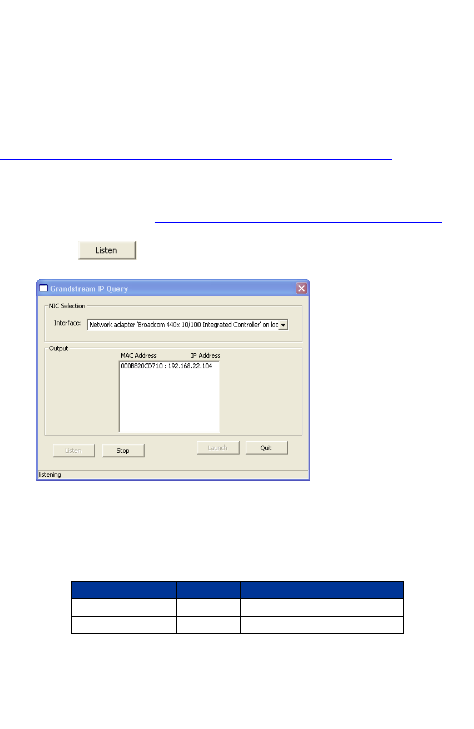
ACCESSING THE WEB CONFIGURATION MENU
1. Navigate your browser to: http://www.grandstream.com/DOWNLOAD/IPQuery/IPQuery.zip
2. Run the Grandstream IPQuery tool, that you just downloaded.
3. Click on button in order to begin device detection
4. The detected devices will appear in the Output field
END-USER CONFIGURATION
When the Web Configuration Menu is accessed, the GXW410x will respond with a login screen. There
are two default passwords for the login page:
User Level: Password: Web pages allowed:
End-user Level 123 Only Status and Basic Settings
Administrator Level admin All pages can be browsed.

After login, the following page is the Basic Configuration page, explained in detail in Table 6: Web
Log-in Definition.
TABLE 6: WEB LOG-IN DEFINITIONS (BASIC SETTINGS PAGE)
Web Access Select HTTP or secure HTTPS protocol for Web Access
Web Port By default, HTTP uses port 80 and HTTPS uses port 443. This field is for customizable
web port.
End-user Password This contains the password to access the End-user Web Configuration Menu (Status and
Basic Settings). This field is case sensitive with a maximum length of 25 characters.
IP Address There are two modes to operate the GXW410x:
DHCP mode: all the field values for the Static IP mode are not used (even though they are
still saved in the Flash memory.) The GXW410x acquires its IP address from the first
DHCP server it discovers from the LAN it is connected.
Using the PPPoE feature: set the PPPoE account settings. The GXW410x will establish a
PPPoE session if any of the PPPoE fields is set.
Static IP mode: configure the IP address, Subnet Mask, Default Router IP address, DNS
Server 1 (primary), DNS Server 2 (secondary) fields.
DHCP hostname This option specifies the name of the client. This field is optional but may be required by
some Internet Service Providers. Default is blank.
DHCP domain This option specifies the domain name that client should use when resolving hostnames
via the Domain Name System. Default is blank.
DHCP vendor class ID Used by clients and servers to exchange vendor-specific information. Default is
Grandstream GXW410x.
PPPoE account ID PPPoE user name. Necessary if ISP requires you to use a PPPoE (Point to Point Protocol
over Ethernet) connection.
PPPoE password PPPoE account password.
PPPoE Service Name This field is optional. If your ISP uses a service name for the PPPoE connection, enter the
service name here. Default is blank.
Preferred DNS server This field will let the user enter a preferred DNS server to be used instead of the one
acquired by the service provider.
Time Zone Controls how the date/time is displayed according to the specified time zone.
Allow DHCP Option 2
to override Time Zone
Settings
Default is No. If set to Yes, time zone settings will originate from the DHCP server.

Daylight Savings Time This parameter controls whether the displayed time will be daylight savings time or not. If
set to “Yes” and the Optional Rule is empty, then the displayed time will be 1 hour ahead
of normal time. The “Automatic Daylight Saving Time Rule” shall have the following syntax:
start-time;end-time;saving
Both start-time and end-time have the same syntax:
Month ,day ,weekday ,hour ,minute
month: 1,2,3,..,12 (for Jan, Feb, .., Dec)
day: [+|-]1,2,3,..,31
weekday: 1, 2, 3, .., 7 (for Mon, Tue, .., Sun), or 0 which means the daylight saving rule is
not based on week days but based on the day of the month.
hour: hour (0-23),
minute: minute (0-59)
If “weekday” is 0, it means the date to start or end daylight saving is at exactly the given
date. In that case, the “day” value must not be negative.
If “weekday” is not zero and “day” is positive, then the daylight saving starts on the first
“day”th iteration of the weekday (1st Sunday, 3rd Tuesday etc). If “weekday” us not zero
and “day” is negative, then the daylight saving starts on the last “day”th iteration of the
weekday (last Sunday, 3rd last Tuesday etc). The saving is in the unit of minutes. The
saving time may also be preceded by a negative (-) sign if subtraction is desired instead of
addition. The default value for “Automatic Daylight Saving Time Rule” shall be set to
“03,11,0,02,00;11,04,0,02,00;60” which is the rule for US.
Examples:
US where daylight saving time is applicable: 03,11,0,02,00;11,4,0,02,00;60
This means the daylight saving time starts from 11th March at 2AM and ends November 4th
at 2AM. The saving is 60 minutes (1hour).
You may also access the Device Status page which provides details of the GXW product. The Device
Status page terms are defined in Table 7: Status Page Definitions.
TABLE 7: STATUS PAGE DEFINITIONS
Hardware Revision Hardware version number: Main Board, Interface Board
MAC Address The device ID in HEX format. This is a very important ID for ISP troubleshooting.
IP Address This field shows WAN IP address of GXW410x
Product Model This field contains the product model info (GXW4104 or GXW4108)
Software Version Program: This is the main software release. Boot and Loader are not changed often.
System Up Time This field shows system up time since the last reboot.
Registered This field indicates whether the different SIP Accounts configured under Channels page
are successfully registered to the SIP server(s).

FXO Line Connected This field will give the status of each physical FXO Line connected to the Gateway. It will
update the status regularly.
Yes - Connected and Idle
Busy - Connected and Busy
No - Not connected
Additionally it will also provide real time Caller ID information of Incoming as well as
Outgoing calls.
PPPoE Link Up This field shows whether the PPPoE connection is running if connected to DSL modem.
Detected NAT Type This field shows what kind NAT the GXW410x is connected to via its WAN port. It is
based on STUN protocol.

ADVANCED USER SETTINGS
ADVANCED USER CONFIGURATION
The end-user needs to login to the advanced user configuration page the same way as for the basic
configuration page.
Advanced User configuration includes the end-user configuration and advanced configurations including:
SIP configuration, Codec selection, NAT Traversal Setting and other miscellaneous configuration.
TABLE 8: ADVANCED CONFIGURATION PAGE DEFINITIONS
Admin
Password
Administrator password. Only the administrator can configure the “Advanced Settings” page.
Password field is purposely left blank for security reasons. The maximum password length is 25
characters.
G723 Rate G723 encoding rate (6.3kbps or 5.3kbps)
Voice Frames
per Tx
This field contains the number of voice frames to be transmitted in a single packet. When setting
this value, the user should be aware of the requested packet time (used in SDP message) as a
result of configuring this parameter. This parameter is associated with the first vocoder in the
above vocoder Preference List or the actual used payload type negotiated between the 2
conversation parties at run time.
For example if the first vocoder is configured as G723 and the “Voice Frames per TX” is set to be
2, then the “ptime” value in the SDP message of an INVITE request will be 60ms because each
G723 voice frame contains 30ms of audio. Similarly, if this field is set to be 2 and if the first
vocoder chosen is G729 or G711 or G726, then the “ptime” value in the SDP message of an
INVITE request will be 20ms.
If the configured voice frames per TX exceeds the maximum allowed value, the gateway will use
and save the maximum allowed value for the corresponding first vocoder choice. The maximum
value for PCM is 10(x10ms) frames; for G726, it is 20 (x10ms) frames; for G723, it is 32 (x30ms)
frames; for G729/G728, 64 (x10ms) and 64 (x2.5ms) frames respectively.
Layer 3 QoS This field defines the layer 3 QoS parameter which can be the value used for IP Precedence or
Diff-Serv or MPLS. Default value is 48. Its range lies from 0 to 63.
Layer 2 QoS This contains the value used for layer 2 VLAN tag.
802.1q / VLAN tag: Default value is 0. Range lies from 0 to 4095.
802.1p Priority value: Default value is 0. Range lies from 0 to 7.
*** The above 2 settings need to be supported on the network and then configured accordingly on
the GXW410x. Incorrect configuration will cause blocked access, which will result in Factory Reset
as the only option to renew access.
Local RTP port This parameter defines the local RTP-RTCP port pair the GXW410x will listen and transmit. It is
the base RTP port for channel 0. When configured, channel 0 will use this port _value for RTP and
the port_value+1 for its RTCP; channel 1 will use port_value+2 for RTP and port_value+3 for its
RTCP and so on. The default value is 5004.
Use Random
Port
This parameter, when set to Yes, will force random generation of both the local SIP and RTP ports.
This is usually necessary when multiple GXW410xs are behind the same NAT.
Keep-alive
interval
This parameter specifies how often the GXW410x sends a blank UDP packet to the SIP server in
order to keep the “hole” on the NAT open. Default is 20 seconds.
Use NAT IP NAT IP address used in SIP/SDP message. Default is blank.

STUN Server IP address or Domain name of the STUN (Simple Traversal of UDP through NATs) server.
Firmware
Upgrade &
Provisioning
This radio button will enable GXW410x to download firmware or configuration file through either
TFTP or HTTP.
Via TFTP Server If selected, the GXW410x will attempt to retrieve new configuration file or new code image from the
specified TFTP server at boot time. It will make up to 5 attempts before timeout and then it will start
the boot process using the existing code image in the Flash memory. If a TFTP server is
configured and a new code image is retrieved, the new downloaded image will be verified and then
saved into the Flash memory.
Note: Please do NOT interrupt the TFTP upgrade process (especially the power supply) as this will
damage the device. Depending on the network environment this process can take up to 25 or 30
minutes.
Via HTTP Server The URL for the HTTP server used for firmware upgrade and configuration via HTTP.
For example, http://provisioning.mycompany.com:6688/Grandstream/
Here “:6688” is the specific TCP port that the HTTP server is listening at, it can be omitted if using
default port 80.
Note: If Auto Upgrade is set to No, GXW410x will only do HTTP download once at boot up.
Firmware Server
Path
IP address or domain name of firmware server.
Config Server
Path
IP address or domain name of configuration server.
Firmware File
Prefix
Default is blank. If configured, GXW400X will request firmware file with the prefix. This setting is
useful for ITSPs. End-user should keep it blank.
Firmware File
Postfix
Default is blank. End-user should keep it blank.
Config File
Prefix
Default is blank. End-user should keep it blank.
Config File
Postfix
Default is blank. End-user should keep it blank.
Allow DHCP
Option 66 to
override server
Default value is No. If set to Yes, configuration file will originate from the DHCP server.
Automatic
Upgrade
Choose Yes to enable automatic upgrade and provisioning. In “Check for new firmware every”
field, enter the number of minutes to enable GXW410x to check the server for firmware upgrade or
configuration. When set to No, GXW410x will only do upgrade once at boot up. Other options are:
“ Always check for New Firmware.”
“ Check New Firmware only when F/W pre/suffix changes”
“ Always skip the Firmware check”
Authenticate
Conf File
If set to Yes, configuration file is authenticated before acceptance. This protects the configuration
from an unauthorized change.

DTMF Payload
Type
This parameter sets the payload type for DTMF using RFC2833. Default is 101.
Syslog Server The IP address or URL of System log server. This feature is especially useful for ITSP (Internet
Telephone Service Provider)
Syslog Level Select the ATA to report the log level. Default is NONE. The level is one of DEBUG, INFO,
WARNING or ERROR. Syslog messages are sent based on the following events:
1. product model/version on boot up (INFO level)
2. NAT related info (INFO level)
3. sent or received SIP message (DEBUG level)
4. SIP message summary (INFO level)
5. inbound and outbound calls (INFO level)
6. registration status change (INFO level)
7. negotiated codec (INFO level)
8. Ethernet link up (INFO level)
9. SLIC chip exception (WARNING and ERROR levels)
10. memory exception (ERROR level)
The Syslog uses USER facility. In addition to standard Syslog payload, it contains the following
components: GS_LOG: [device MAC address][error code] error message
Example: May 19 02:40:38 192.168.1.14 GS_LOG: [00:0b:82:00:a1:be][000] Ethernet link is up
NTP server URI or IP address of the NTP (Network Time Protocol) server, which will be used by the phone to
synchronize the date and time.
Allow DHCP
Option 42 to
override an NTP
server
Default value is No. If set to Yes, the NTP server will originate from the DHCP server.
Enable Video
Surveillance
When set to Yes, GXW410x will start converting video feed received from analog camera to IP
packets. In order to view this video feed, please follow instructions given under Video Surveillance
chapter on page 23.
RTSP Port By default it is 554.

CONFIGURING THE FXO CHANNELS
Configuring the FXO channels on the GXW410x gateway is an easy process. Follow the GUI interfaces.
The Device Status page terms are defined in Table 9: FXO Lines Configuration Definitions. An
example of the Channel Dialing Configuration is shown in Figure 6. Please note the default is always
configured. The user has the option to change the default settings as described in the Table 9.
TABLE 9: FXO LINES CONFIGURATION DEFINITIONS
Syntax for Channel Specific Settings:
Default: ch1-8:X; {all channels 1 to 8 are set to use value X}
Additional Examples:
ch1,3-6:10;ch2,7-8:12 {channels 1,3,4,5 and 6 are set to use value 10 while channels 2,7 and 8
are set to use value 12.
Enable Current
Disconnect
When set to Y, Current Disconnect is enabled. Certain PSTN COs require this to be enabled, in
order to realize disconnect signal from PSTN side. Default is Y.
If enabled use threshold: Default is 100ms. Range is 40ms to 800ms.
Certain PSTN service providers have a threshold time within which the line stabilizes after off-
hook. It is entirely dependent on provider, however if you experience PSTN line detection issues,
please modify this setting appropriately in 100ms increments.
If you are not sure if this option should be enabled please refer to Table 10 (FXO Lines Test Tab
Definition). This tool will run an automated test to determine the proper PSTN configuration that
the gateway should have to work with your Service Provider or analog PBX.
Enable Tone
Disconnect
Default is No. If PSTN provider uses call progress tones then it should be set to Yes in order to
realize disconnect tone. Please configure accurate Call Progress Tones on Channels web page
based on PSTN provider (or traditional PBX) settings.
If you are not sure if this option should be enabled or what Call Progress Tones are required
please refer to Table 10 (FXO Lines Test Tab Definition). This tool will run an automated test to
determine the proper PSTN configuration that the gateway should have to work with your Service
Provider or analog PBX.
Enable Polarity
Reversal
Default is No. This should be set to Yes only if the FXO lines are subscribed to PR service from
PSTN Service provider. It is merely a PR detect feature.
***Note: If there is no PR service from provider on the FXO line, and this setting is configured to
Yes, calls will not be successful.
Silence Timeout Terminate call after long silence detected. Default is 60 seconds, max 65536.
AC Termination
Impedance
Selects the impedance of the analog line connected to the FXO port on the GXW410x. Here is
some basic information which may be helpful for initial configuration:
600 Ohm – North America;
270 Ohm + (750 Ohm || 150 nF) -- Most of Europe
220 Ohm + (820 Ohm || 120 nF) – Australia, New Zealand
220 Ohm + (820 Ohm || 115 nF) – Austria, Bulgaria, Germany, Slovakia, South Africa
370 Ohm + (620 Ohm || 310 nF) – UK., India
If this parameter is not configured properly you may experience echo or noise in the line. Please
refer to Table 10 (FXO Lines Test Tab Definition). This tool will run an automated test to
determine the correct impedance value to match your lines.

Wait for Dial-tone Default is No. When set to Yes, the gateway will recognize dial-tone from the Central Office (CO)
before it completes a call. If you can’t make an outbound call, set this is Yes. if this is set to Yes
make sure you have configured the dial tone settings correctly in the Channels tab and that there
is not any major noise interference in the line.
Stage Method Syntax - ch1-8:1; {all channels 1 to 8 are set to value 1 or 2}
Stage method can be set to either 1 or 2.
Set this parameter to 1 if you need to make a direct PSTN call from a VOIP endpoint. When you
set it to 2, you will first dial one of the VOIP channel accounts from the VOIP endpoint, this will
result in getting a PSTN line dial-tone to then dial out the destination PSTN number.
Most implementations require this setting to be configured to 1.
Min. Delay before
Dial PSTN
Default is 500ms. This needs to be equal to or greater than the Current Disconnect threshold
setting. Once the threshold is reached the gateway can dial out. This parameter should only be
used if there are PSTN line detection issues.
Unconditional Call
Forward to VOIP:
This is an extremely important setting to make sure incoming PSTN calls are picked up and
forwarded to the correct VOIP destination.
User ID - This parameter allows users to configure a User ID or extension number to be
automatically dialed upon FXO line off-hook.
SIP Server - You also need to specify the Profile of the user id configured above (p1 stands for
Profile 1, p2 stands for Profile 2 and so on).
SIP Destination Port - Along with the user-id and Profile, you also have the option to choose the
destination port where you would like to send the call. By default it should be set to ch1-x:5060; (x
can be 4 or 8 depending on number of ports).
We can also specify a different destination for each port. For example under User ID we can type
in: ch1:104;ch2:227;ch3-5:501;ch6,7:856.
Under Sip Server we can type in: ch1:p1;ch2-4:p2;ch5:p3
Under Sip Destination Port we can type in: ch1-2:5060;ch2:7080;ch3-8:5066++
Number of Rings
Before Pickup Default is 4. This is the number of rings the gateway will wait to send the call to the
VOIP side in case the Caller ID has yet to be detected. If there's CID information the
call will be sent right away. If your lines don't have the CID service set this to 1.

Caller ID Scheme The GXW410x supports 5 different types of schemes:
1. Bellcore (US standard)
2. ETSI-FSK during ringing
3. ETSI-FSK prior to ringing with DTAS
4. ETSI-FSK prior to ringing with LR
5. ETSI-FSK prior to ringing with PR
6. ETSI-DTMF during ringing
7. ETSI-DTMF prior to ringing with DTAS
8. ETSI-DTMF prior to ringing with PR
9. ETSI-DTMF prior to ringing with PR
10. SIN 227 - BT
11. NTT (Japanese standard)
Please check with your PSTN service provider (or traditional PBX specs) for which caller ID
scheme they/it support. If you are not sure about which to use please refer to Table 10 (FXO
Lines Test Tab Definition). This tool will run an automated test to determine the proper Caller ID
Scheme so the gateway can properly detect the Caller ID.
Similarly to the cases explained above we can specify a caller ID scheme for each channel
independently.
Caller ID Transport
type
Default is “relay via From header”. You may also select :
“relay via P_Asserted_Identity header”
“Disable” : Caller ID feature will be disabled.
“Send anonymous” : All calls forwarded to VOIP end will be sent as anonymous.
T.38 Setting This setting allows you to make several options related to facsimile.
You can select the method: T.38 or Pass through (G711)
You can select the fax transmission rates (2400/4800/7200/9600/12000/14400bps)
You can enable or disable ECM (Error Checking Mode)

TABLE 10: FXO LINE TEST TAB DEFINITIONS
Note: The user can only test the parameters for only one of the PSTN lines at the
same time. In all cases please enter the telephone numbers as if the lines were to
dial each other locally.
For the AC Impedance Test we only need to select the line to be tested by clicking on
the AC impedance box corresponding to that line, telephone numbers are optional.
Remember that the AC impedance test is usually used to reduce the echo that might
be present in the line.
For the CPT test (call progress tones) we will test current disconnect as well. You will
need 2 telephone numbers to perform the test. You can only perform the test on one
line (row) at the same time and it will be the one that has the box checked for testing.
This tested line will use another line connected to the gateway to perform the test by
calling into it, this is why you will have to enter the telephone number for a second
line to help with the test.
For CID detection you will need 2 telephone numbers to perform the test. You can
only perform the test on one line (row) at the same time and it will be the one that has
the box checked for testing. This tested line will use another line connected to the
gateway to perform the test by calling into it, this is why you will have to enter the
telephone number for a second line to help with the test.
To perform the test, please select the line you want to test and the desired test to be
performed. Enter the information for this line as well as a second line if necessary.
Then click on the update button and then reboot. Log back in and now you should
see the information for the line selected as well as the check box already marked
already there. Go ahead and start the test now, please wait a few minutes until the
test is done.
Notes:
It is not required to enter a telephone number when testing for impedance, as the
system does not place any actual calls for the test.
If you log into the Web Interface while the test is running will not interrupt the
process.
Line # Enter the telephone (PSTN) number that corresponds to this line. Enter it as if you
were going to dial it locally
AC Impedance Select this box if you want to test for impedance on the line that is on the same row
as the checked box. Remember that you can only check one item at the same time.
CPT Detection Select this box if you want to test for call progress tones and current disconnect
threshold on the line that is on the same row as the checked box. Remember that
you can only check one item at the same time.
External Number Enter an external telephone (PSTN) number to be used as an auxiliary number for
the test. This is used only if we do not have at least 2 PSTN lines connected to the
gateway. This is only used for CPT and current disconnect threshold testing. In order
to use this function you will have to monitor the Syslog output. This is only reserved
for very advanced users
External Call Timeout This is the time the GXW will wait for the external telephone number to pick up during
the test.

Apply test results
automatically
Default is No. If selected on Yes, then all the results from the test will be applied
automatically. If you select No you will have to monitor the Syslog output. This is only
reserved for very advanced users.
Apply test results to all
ports
Default is No. If selected on Yes, then all the test results will be applied to all ports on
the gateway. If all the lines belong to the same service provider or PBX it will make
sense to apply the results to all ports.
Error Timeout This is the time the gateway will wait to exit the test mode, when something
unexpected or an error has occurred.
TABLE 11: CHANNELS PAGE DEFINITIONS
Note – The channels here are basically SIP endpoints that will act as clients
registering to the SIP Server configured under the appropriate Profile page.
Channels It should be set same as the channel number (i.e 1, 2..4 or 8 depending on number of
FXO ports). It is NOT the same as SIP Account ID.
SIP User ID This is the SIP account information. Enter the SIP User ID part of the account.
Authentication ID SIP service subscriber’s Authenticate ID used for authentication. It can be identical
to, or different from SIP User ID.
Authentication Password SIP account password needs to be entered here.
Note: After entering the password, it will show up as blank but the password still
remains active.
Profile ID Select the corresponding Profile ID (1/2/3). Profiles are SIP Server configurations.
Call Progress Tones Using these settings, user can configure tone frequencies according to user
preference. By default, the tones are set to North American frequencies.
Frequencies should be configured with known values to avoid uncomfortable high
pitch sounds. ON is the period of ringing (ON time in ms) while OFF is the period of
silence. In order to set a continuous ring, OFF should be zero. Otherwise it will ring
ON ms and a pause of OFF ms and then repeat the pattern.
•“Dial tone”
•“Ringback tone”
•“Busy/Re-order tone”
•“Confirmation tone”
Please refer the document below to determine your local call progress tones
(http://www.itu.int/ITU-T/inr/forms/files/tones-0203.pdf) or run the FXO Line Test
(Table 10).
Channel Voice Settings Channel voice settings mentioned below.
Tx to PSTN Audio Gain (dB) Allows user to set a value in dB for transmission to PSTN Audio Gain. Default is 1.
Range is from -12 to 12dB.
Rx from PSTN Audio Gain
(dB)
Allows user to set a value in dB for receive from PSTN Audio Gain. Default is 0.
Range is from -12 to 12dB.
Silence Suppression This controls the silence suppression/VAD feature of G723 and G729. If set to “Yes”,
when a silence is detected, small quantity of VAD packets (instead of audio packets)
will be sent during the period of no talking. If set to “No”, this feature is disabled.

Echo Cancellation When set to Y, Echo cancellation is enabled.
Channel specific Setting Channel specific settings mentioned below.
DTMF Method This parameter specifies the mechanism to transmit DTMF digits. There are7 modes
supported: in audio which means DTMF is combined in audio signal (not very reliable
with low bit-rate codec), via RTP (RFC2833), or via SIP INFO. Multiple DTMF
transmission schemes can be selected.
•1 – in-audio
•2 – RFC2833
•3 – in-audio and RFC2833
•4 – SIP Info
•5 – in-audio and RFC2833
•6 – SIP Info and RFC2833
1. 7 – in-audio, RFC2833, and SIP Info
No Key Entry Timeout Default is 4 seconds.
Local SIP Listen Port Default is ch1-8:5060++;. The ++ indicates increments by 2, so port 1 is set at 5060,
port at 5062 and so on. This setting can be used with Round Robin and/or Flexible
setting below to configure different ports to be placed under different Round Robin
groups.
SRTP Mode Default is disabled for all ports. The user can select to either enable it but not force it
or force it on an individual port basis. When used the communication will be sent
using Secure RTP.
Round Robin and/or
Flexible
Default is rr:1-8;
The syntax is pretty straight-forward here. The rr stands for Round Robin and the
numbers stand for the ports that belong to that round robin group.
For example:
rr:1-8; -> Round robin within the first 8 ports i.e. outgoing calls will be forwarded to
the next available port within the group of ports 1 to 8.
rr:1,3-6,8;rr:2,7; -> Round robin within port 1,3,4,5,6 and 8; Second round robin group
within ports 2 and 7 i.e. outgoing calls to ports 1,3,4,5,6 and 8 will be forwarded to the
next available port within this group ONLY. Outgoing calls to port 2 and 7 will be
forwarded to the next available port between ports 2 and 7 ONLY.
** In order to terminate a call on FXO port 2 or 7 you will need to change its Local
SIP Listen port accordingly.
Prefix to specify Port
(1 stage dialing method)
Default is 99.
Syntax to USE this feature: prefix# (that is 99) + ch# (could be anything from 1 to 8) +
dialing# will result in this call forwarded to FXO port (ch#) immediately.

TABLE 12: CHANNELS PAGE DEFINITIONS
Dial Plan The Dial Plan feature implemented is applicable for VOIP to PSTN calls only. You may
configure a dial plan based on the following grammar:
1. Accept Digits: 1,2,3,4,5,6,7,8,9,0,*,#,A,a,B,b,C,c,D,d
2. Grammar:
x - any digit from 0-9;
xx+ - at least 2 digit number;
xx. - at least 2 digit number;
^ - exclude;
[3-5] - any digit of 3, 4, or 5;
[147] - any digit 1, 4, or 7;
<2=011> - replace digit 2 with 011 when dialing
WARNING - illegal input will fall back to default
Example 1: {[369]11 | 1617xxxxxxx} - Allow 311, 611, 911, and any 10 digit
numbers of leading digits 1617.
Example 2: {^1900x+ | <=1617>xxxxxxx} - Block any number of leading digits 1900
and add prefix 1617 for any dialed 7 digit numbers.
Example 3: {1xxx[2-9]xxxxxx | <2=011>x+} - Allow any length of number with
leading digit 2 and 10 digit-numbers of leading digit 1 and leading exchange number
between 2 and 9;
If leading digit is 2, replace leading digit 2 with 011 before dialing
Default: PSTN Outgoing - {x+}
Note: If you do not plan to use this feature set to default {x+}
Hook flash Duration
(X10ms)
Default 600ms. This value can accept any value in the 100-2000ms range.
Use DTMF Parameter
from RFC2833 or SIP Info
Default Yes, No means to use DTMF parameter settings according to DTMF Digit
Length, DTMF Digit Volume and DTMF Dial Pause.
DTMF Digit Length Default value is 100ms. Please not that the value will be multiplied by 10ms
DTMF Digit Volume Default value is -11dB.
DTMF Dial Pause Default value is 100ms. Please note that the value will be multiplied by 10ms.
PROFILES
Profiles are basically IP-PBX / SIP Server configuration templates. If you have more than one IP-PBX
system or SIP Server that you would like to use with the GXW410x, then you can configure Profile 2 or 3.
Note: Make sure you select the correct profile for each channel under Channels PAGE
TABLE 13: PROFILE PAGE DEFINITIONS
Activate Profile When set to Yes the SIP Profile is activated.
Profile Name A name to identify a Profile.

SIP Server SIP Server’s IP address or Domain name provided by VoIP service provider.
Outbound Proxy IP address or Domain name of Outbound Proxy, or Media Gateway, or Session Border
Controller. Used by GXW410x for firewall or NAT penetration in different network
environments. If symmetric NAT is detected, STUN will not work and ONLY outbound proxy
can correct the problem.
Use DNS SRV: Default is No. If set to Yes the client will use DNS SRV to look up server.
User ID is Phone
Number
If the GXW410x has an assigned PSTN telephone number, this field should be set to “Yes”.
Otherwise, set it to “No”. If “Yes” is set, a “user=phone” parameter will be attached to the
“From” header in SIP request.
SIP Registration This parameter controls whether the GXW410x needs to send REGISTER messages to the
SIP Server. The default setting is “Yes”.
Unregister on
Reboot
Default is No. If set to yes, the SIP user’s registration information will be cleared on reboot.
Register Expiration This parameter allows the user to specify the time frequency (in minutes) for the GXW410x to
refresh its registration with the specified registrar. The default interval is 60 minutes (or 1
hour). The maximum interval is 65535 minutes (about 45 days).
SIP Registration
Failure Retry Wait
Time
This parameter is most used by Service Providers. It prevents message REGISTER overload
of SIP Server in case of downtime due to maintenance or power failure. By increasing interval
length, common message load is decreased. Interval range is 1 – 3600 seconds.
NAT Traversal This parameter defines whether the GXW410x NAT traversal mechanism will be activated or
not. If activated (by choosing “Yes”) and a STUN server is also specified, then the GXW410x
will behave according to the STUN client specification. Under this mode, the embedded STUN
client inside the GXW410x will attempt to detect if and what type of firewall/NAT it is sitting
behind through communication with the specified STUN server. If the detected NAT is a Full
Cone, Restricted Cone, or a Port-Restricted Cone, the GXW410x will attempt to use its
mapped public IP address and port in all of its SIP and SDP messages. If the NAT Traversal
field is set to “Yes” with no specified STUN server, the GXW410x will periodically (every 20
seconds or so) send a blank UDP packet (with no payload data) to the SIP server to keep the
“hole” on the NAT open.
Proxy-Require SIP Extension to notify SIP server that the unit is behind the NAT/Firewall.
Early Dial Default is No. Use only if proxy supports 484 response.
Session Expiration Grandstream implemented SIP Session Timer. The session timer extension enables SIP
sessions to be periodically “refreshed” via a SIP request (UPDATE, or re-INVITE. Once the
session interval expires, if there is no refresh via a UPDATE or re-INVITE message, the
session will be terminated. Session Expiration is the time (in seconds) at which the session is
considered timed out, if no successful session refresh transaction occurs beforehand. The
default value is 180 seconds.
Min-SE The minimum session expiration (in seconds). The default value is 90 seconds.
Caller Request
Timer
If selecting “Yes” the phone will use session timer when it makes outbound calls if remote
party supports session timer.
Callee Request
Timer
If selecting “Yes” the phone will use session timer when it receives inbound calls with session
timer request.

Force Timer If selecting “Yes” the phone will use session timer even if the remote party does not support
this feature. Selecting “No” will allow the phone to enable session timer only when the remote
party support this feature. To turn off Session Timer, select “No” for Caller Request Timer,
Callee Request Timer, and Force Timer.
UAC Specify
Refresher
As a Caller, select UAC to use the phone as the refresher, or UAS to use the Callee or proxy
server as the refresher.
UAS Specify
Refresher
As a Callee, select UAC to use caller or proxy server as the refresher, or UAS to use the
phone as the refresher.
Force INVITE Session Timer can be refreshed using INVITE method or UPDATE method. Select “Yes” to
use INVITE method to refresh the session timer.
Enable 100rel The use of the PRACK (Provisional Acknowledgement) method enables reliability to be offered
to SIP provisional responses (1xx series). This is very important if PSTN inter-networking is to
be supported. A user’s request to use reliable provisional responses is invoked by the 100rel
tag which is appended to the value of the required header of initial signalling messages.
Refer-to uses
Target Contact
Default is NO. If set to YES, then for Attended Transfer, the “Refer-To” header uses the
transferred target’s Contact header information.
INVITE Ring-no-
answer Timeout
In case incoming call has arrived from PSTN to VoIP and INVITE message was generated by
GXW device, the call will be disconnected after pre-configured timeout if not answered by VoIP
extension.
Preferred Vocoder The GXW410x supports up to 5 different Vocoder types including G.711 A-/U-law, GSM,
G.723.1, G.729A/B. The user can configure Vocoders in a preference list that will be included
with the same preference order in SDP message. The first Vocoder in this list can be entered
by choosing the appropriate option in “Choice 1”. Similarly, the last Vocoder in this list can be
entered by choosing the appropriate option in “Choice 8”.
Special Feature Default is Standard. Choose the selection to meet some special requirements from Soft Switch
vendors like Nortel, Broadsoft, etc.
SAVING THE CONFIGURATION CHANGES
When changes are made, press the “Update” button in the Configuration Menu. The GXW410x will
display the following screen to confirm that the changes have been saved. To activate changes, reboot
or power cycle the GXW410x after all changes are made.
REBOOTING FROM REMOTE
The administrator can remotely reboot the unit by pressing the “Reboot” button at the bottom of the
configuration menu. The following screen will indicate that rebooting is underway.
The user can re-login to the unit after waiting for about 30 seconds.

VIDEO SURVEILLANCE
The GXW410x gateway can be used with an Analog Surveillance CCD Camera to perform video
surveillance function. This application should be used in a LAN environment or when both sides have
public IP address.
VIDEO SURVEILLANCE PROCEDURES
Gateway side:
1. In the ADVANCED SETTING page, find the following field and change from default
setting NO to YES, reboot the device.
2. Connect an analog surveillance camera to the VIDEOIN connection at the back panel of
the unit.
PC side (Monitor Device):
1. Download VLC from http://www.videolan.org/vlc/. This is the only player so far that
supports RFC 3984.
2. Launch VLC.
3. Go to Preferences->Input/Codecs->Demuxers->H264, check “Advanced options” in the
bottom. The option “Frames per Second” will show. Change that value to 5 and then save.
4. Go to Preferences->Input/Codecs->Access modules->Real RTSP, check “Advanced
options” in the bottom. The option “Caching value (ms) will show. Change that value to 1000
and then save. You may change it to a smaller value to reduce the delay.
5. If the viewer is under NAT, go to Preferences->Demuxers->Access modules-
>RTP/RTSP, check “Advanced options” in the bottom. The option “Use RTP over RTSP
(TCP)” will show. Check that option box. (Grandstream does NOT recommend this network
environment)
6. Close the Preferences window and go to File->Open Network Stream:
a) Select RTSP as the protocol
b) Enter the URL in the format of rtsp://admin:
ADMIN_PASSWORD@DEVICE_IP_ADDRESS:DEVICE_RTSP_PORT.
Change the blue text according to your configuration:
•ADMIN_PASSWORD is the device’s web configuration password for admin.
•DEVICE_IP_ADDRESS is the device IP.
•DEVICE_RTSP_PORT is the RTSP port setting of the device.
If the port uses default value 554, the port portion can be omitted from the URL
c) Click OK to start the video.
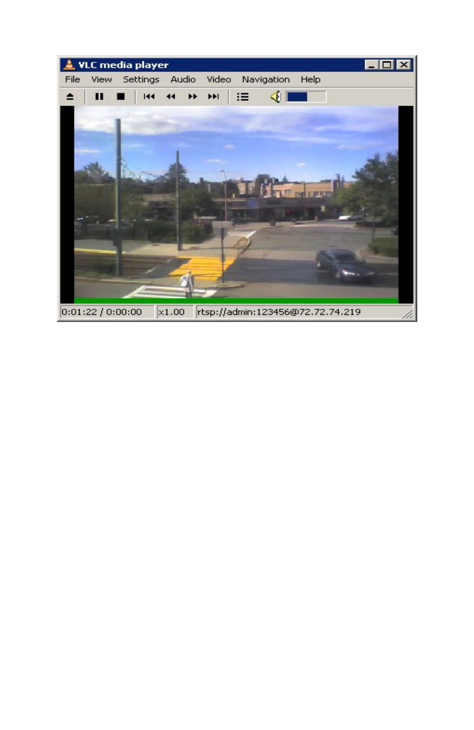
FIGURE 7: SCREEN-SHOT OF VIDEO SURVEILLANCE*
* PC client side running VLC as monitoring station

FIRMWARE UPGRADE
Our latest official release can be downloaded from: http://www.grandstream.com/firmware.html.
Firmware (or software) upgrades can be done either via TFTP or HTTP. The corresponding configuration
settings are on the configuration page. End-users should NOT modify the configuration settings that are
useful for ITSPs. To upgrade your unit firmware, follow these steps:
1. Under Advanced Settings web page, enter your TFTP or HTTP Server IP address (or FQDN)
next to the “Firmware Upgrade: Upgrade Server” field.
2. Select via TFTP or HTTP accordingly.
3. If you plan to use Automatic Upgrade, set it to “Yes”, otherwise No (this will make it check for
upgrade every time you reboot).
UPGRADE THROUGH HTTP
To upgrade firmware via HTTP, the field “Firmware Upgrade and Provisioning: Upgrade Via” needs to be
set to HTTP. The “Firmware Server Path” should be set to where the firmware files are located.
For example: The user can use the following URL in the Firmware Server Path:
firmware.mycompany.com: 6688/Grandstream/1.3.1.6 where firmware.mycompany.com is the FQDN
of the HTTP server. It can also be in IP address format. “:6688” is the TCP port the HTTP server listening
to, default http server listens to port 80. “/Grandstream/1.3.1.6 is the RELATIVE directory to the root dir
on HTTP web server.
UPGRADE THROUGH TFTP
To upgrade firmware via TFTP, set the field “Firmware Upgrade and Provisioning: Upgrade Via” to TFTP.
The TFTP server can be configured in either IP address format or FQDN.
To configure the TFTP server via the Web configuration interface, follow these five steps:
1. Open your browser to input the IP address of the GXW410x.
2. Enter the admin password to enter the configuration screen.
3. Enter the TFTP server address or URL in the “Firmware Server Path” field near the
bottom of the configuration screen.
4. Once the “Firmware Server Path” is set, update the change by clicking the “Update”
button.
5. Reboot or power cycle the unit.
If the configured upgrade server is found and a new code image is available, the GXW410x will retrieve
the new image files by downloading them into the GXW410 gateway’s SRAM. During this stage, the
GXW410x gateway’s LED will blink until the checking/downloading process is completed. Upon
verification of checksum, the new code image will be saved into the Flash. If TFTP fails for any reason
(e.g., TFTP server is not responding, there are no code image files available for upgrade, or checksum
test fails, etc), the GXW410x gateway will stop the TFTP process and simply boot using the existing code
image in the flash.

Firmware upgrade process may take as long as 20 minutes over the Internet, or just 20+ seconds if it is
performed on a LAN. Grandstream recommends conducting firmware upgrades in a controlled LAN
environment if possible.
DOWNLOAD TFTP SERVER
For users who do not have a local TFTP server, Grandstream provides a NAT-friendly TFTP server on
the public Internet for users to download the latest firmware upgrade automatically. Please check the
Services section of Grandstream’s Web site to obtain this TFTP server IP address. Alternatively, user
can download and install a free TFTP or HTTP server in his LAN for a firmware upgrade.
A free Windows version TFTP server can be downloaded from:
http://support.solarwinds.net/updates/New-customerFree.cfm.
Directions for Downloading TFTP Server:
1. Unzip the file and put all of the files under the root directory of the TFTP server.
2. Put the PC running the TFTP server and the GXW410x in the same LAN segment.
3. Go to File -> Configure -> Security to change the TFTP server's default setting from "Receive
Only" to "Transmit Only" for the firmware upgrade.
4. Start the TFTP server, in the phone’s web configuration page.
5. Configure the Firmware Server Path with the IP address of the PC.
6. Update the change and reboot the unit.
You can also download the free HTTP server from http://httpd.apache.org or just use Microsoft IIS web.

RESTORE FACTORY DEFAULT SETTING
WARNING! Restoring the Factory Default Setting will DELETE all configuration information of the phone.
Please BACKUP or PRINT out all the settings before you approach to following steps. Grandstream will
not take any responsibility if you lose all the parameters of setting and cannot connect to your VoIP
service provider.
The ONLY way to restore default factory settings is as follows:
1. Unplug the Ethernet cable.
2. Locate the needle sized hole on the back panel of the gateway next to the Power connection.
3. Enter a thin object in this hole and keep it pressed for about 7 seconds.
4. You will see the Network port LEDs (green and orange) go off and on simultaneously; this
indicates the reset went through.
5. All settings have been erased and the gateway is back to factory settings.
Examples of GXW410x Configurations
APPLICATION ONE: GXW CONNECTED WITH AN IP-PBX OR SIP SERVER
Scenario: A business with a traditional phone system (with or without broadband access) and an IP
PBX or SIP Servers connecting to an Internet Telephone Service Provider (ITSP).
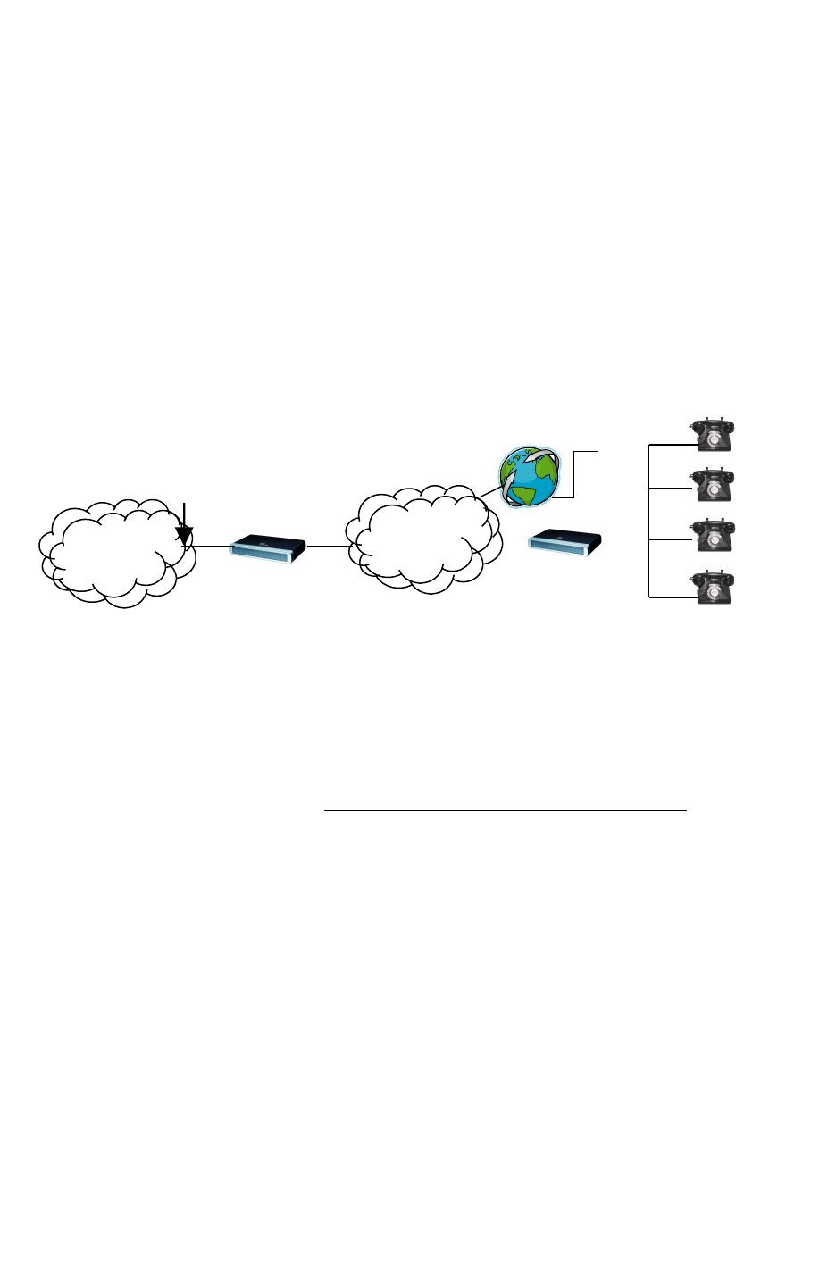
APPLICATION TWO: GXW TO EXTEND A TRADITIONAL PBX SCENARIO
Scenario: a small business with traditional analog PBX lines and broadband access who want to extend
their traditional PBX to virtually anywhere in the world, using the Internet. (Any SIP End point, such as
Grandstream BugeTone, HandyTone, GXP-2000 or GXV-3000 are needed in this scenario)
PSTN
PSTN
Cloud
Cloud
Anywhere in the
world
GXW-
410x
4 or 8
Ports
FXO
Lines
PSTN Analog
Lines
Grandstream IP
Phones
IPPBX or
SIP
Server
IP/LA
N
IP/WA
N
APPLICATION THREE: GXW CONNECTED WITH AN IP-PBX OR SIP SERVER AND VIDEO SURVEILLANCE
Scenario: The GXW410x offers an additional video surveillance port which can be configured for
surveillance. It is the only small business analog gateway that offers this security feature.
Company A -
Boston, MA
6 employees
Any branch,
anywhere
Internet
Internet
Cloud
Cloud
IPPBX or
SIP
Server
Grandstream IP
Phones
PSTN
PSTN
Cloud
Cloud
IP/LAN
GXW-
410x
GXW-410x
IP/LA
N
FXS | IPPBX | SIP
Platform
Any SIP
endpoint
FXO
Lines
Tradition
al
PBX
FXO
Lines
Optio
nal
Anywhere in
the world
Branch A –
Boston, MA
6 employees
Branch B – Denver,
CO
4 employees
Interne
Interne
t Cloud
t Cloud
IPPBX or
SIP
Server
Grandstream IP
Phones
PSTN
PSTN
Cloud
Cloud
IP/LAN
GXW
410x
IPPBX or
SIP Server
IP/LA
N
Grandstream IP
Phones
Anywhere in the
world
GXW
410x
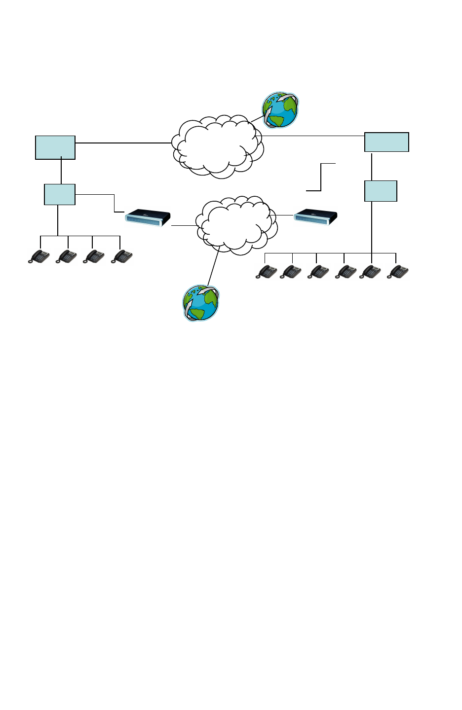
APPLICATION FOUR: USING A GXW FOR PURE IP- IP COMMUNICATION CONFIGURATION
Scenario Four: The GXW410x offers an IP to IP pure IP Communications System configuration, where
all locations use IP phones.
Branch A –
Boston, MA
6 employees
Branch B –
Denver, CO
4 employees
Internet
Internet
Cloud
Cloud
IPPBX or
SIP Server
Grandstream IP
Phones
PSTN
PSTN
Cloud
Cloud
IP/LAN
GXW
410x
IPPBX or
SIP
Server
IP/LAN
Grandstream IP
Phones
Anywhere in the
world
GXW
410x
FCC Warning
This device complies with part 15 of the FCC Rules. Operation is subject to the following two
conditions:
(1) This device may not cause harmful interference, and (2) this device must accept any
interference received, including interference that may cause undesired operation.
Any Changes or modifications not expressly approved by the party responsible for compliance
could void the user's authority to operate the equipment.
FCC 15.105 Class B
(b) For a Class B digital device or peripheral, the instructions furnished the user shall include
the following or similar statement, placed in a prominent location in the text of the manual:
Note: This equipment has been tested and found to comply with the limits for a Class B digital
device, pursuant to part 15 of the FCC Rules. These limits are designed to provide reasonable
protection against harmful interference in a residential installation. This equipment generates,
uses and can radiate radio frequency energy and, if not installed and used in accordance with
the instructions, may cause harmful interference to radio communications. However, there is
no guarantee that interference will not occur in a
particular installation. If this equipment does cause harmful interference to radio or television
reception, which can be determined by turning the equipment off and on, the user is
encouraged to try to correct the interference by one or more of the following measures:
—Reorient or relocate the receiving antenna.
—Increase the separation between the equipment and receiver.
—Connect the equipment into an outlet on a circuit different from that to which the receiver is
connected.
—Consult the dealer or an experienced radio/TV technician for help.