Grandstream Networks HT502V2X ATA User Manual YZZHT502V2X Usermanual
Grandstream Networks, Inc. ATA YZZHT502V2X Usermanual
UserManual.wiki
>
Grandstream Networks
>
HT502V2X User Manual
User Manual
Navigation menu
Upload a User Manual
Namespaces
Wiki Guide
HTML
PDF
Info
Views
User Manual
Discussion / Help
Navigation


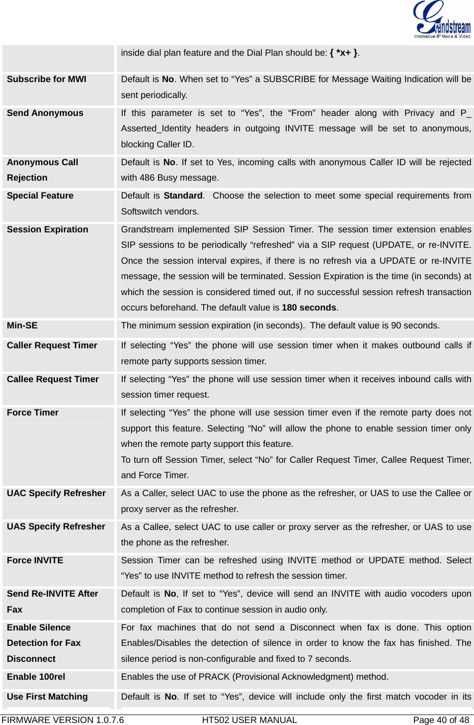
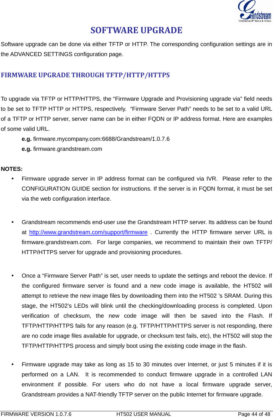
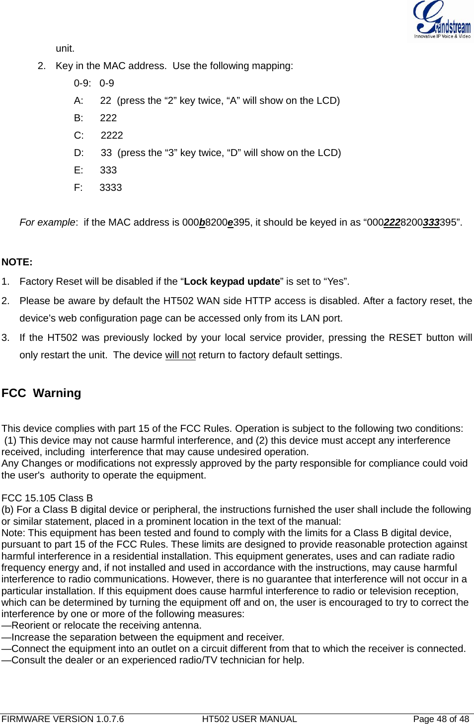
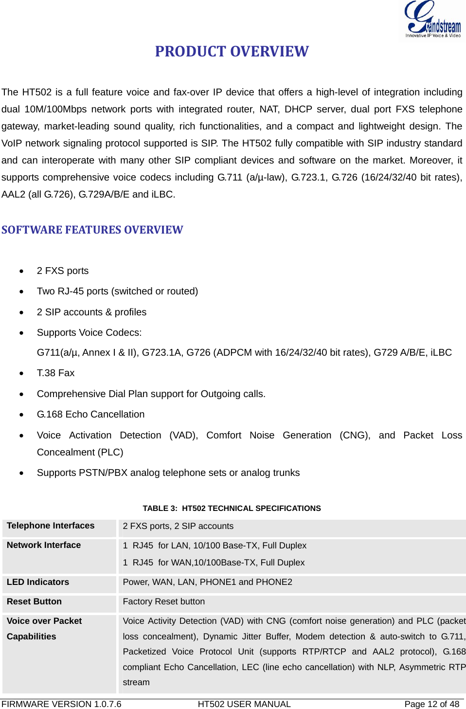
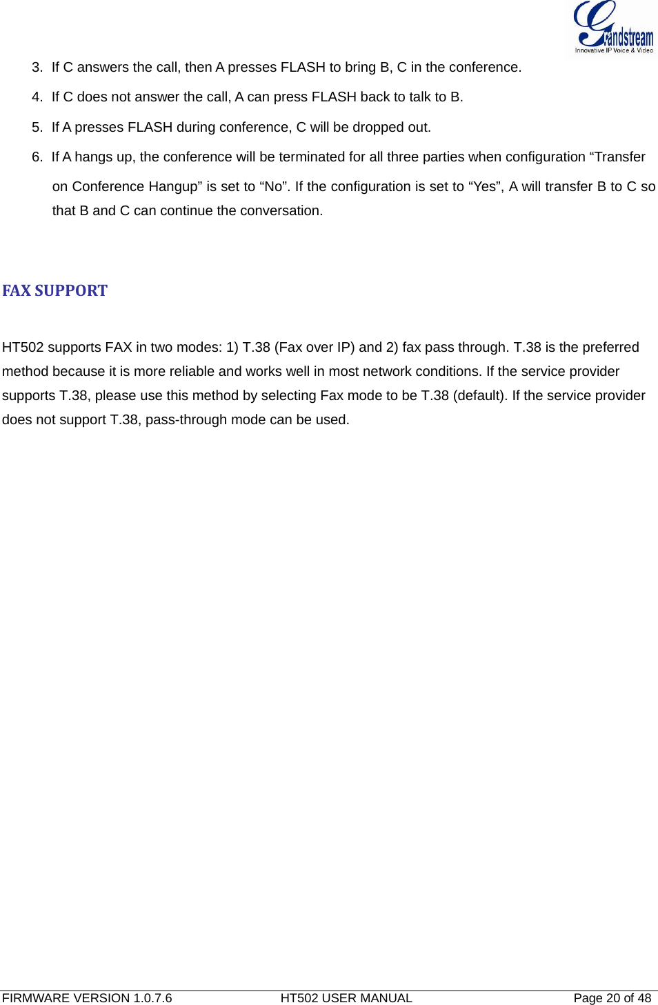
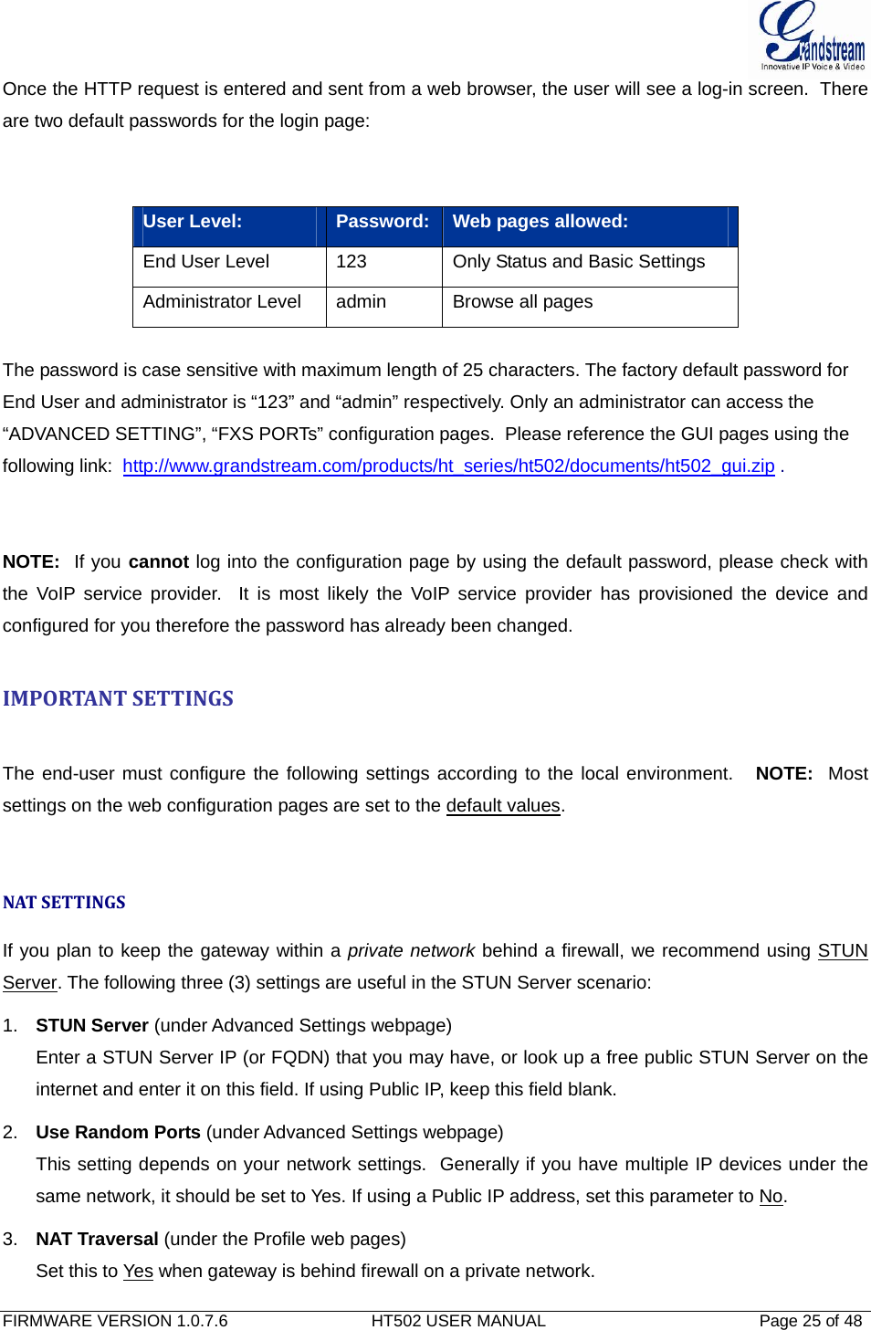
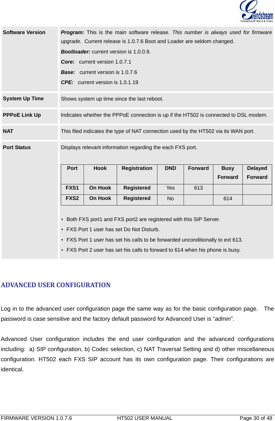
![FIRMWARE VERSION 1.0.7.6 HT502 USER MANUAL Page 6 of 48 CHANGELOG This section documents significant changes from previous versions of HT502 user manuals. Only major new features or major document updates are listed here. Minor updates for corrections or editing are not documented here. CHANGESFROM1.0.6.8USERMANUAL• Added the option to enable/disable hook flash. [Enable Hook Flash] • Added two CPE SSL configuration [CPE SSL Certificate][CPE SSL Private Key] • Added a configuration parameter to set the [Connection Request Port] • Removed DHCP Domain from Web UI • Removed Enable Ring-transfer from Web UI • Added a configuration parameter to set the [Offhook Auto-Dial Delay] • Changed the SSL Web UI decription to [SIP TLS Certificate][SIP TLS Private Key] and [SIP TLS Private Key Password] • Added [CPE] version to Software Version on Web UI](https://usermanual.wiki/Grandstream-Networks/HT502V2X/User-Guide-1842884-Page-6.png)

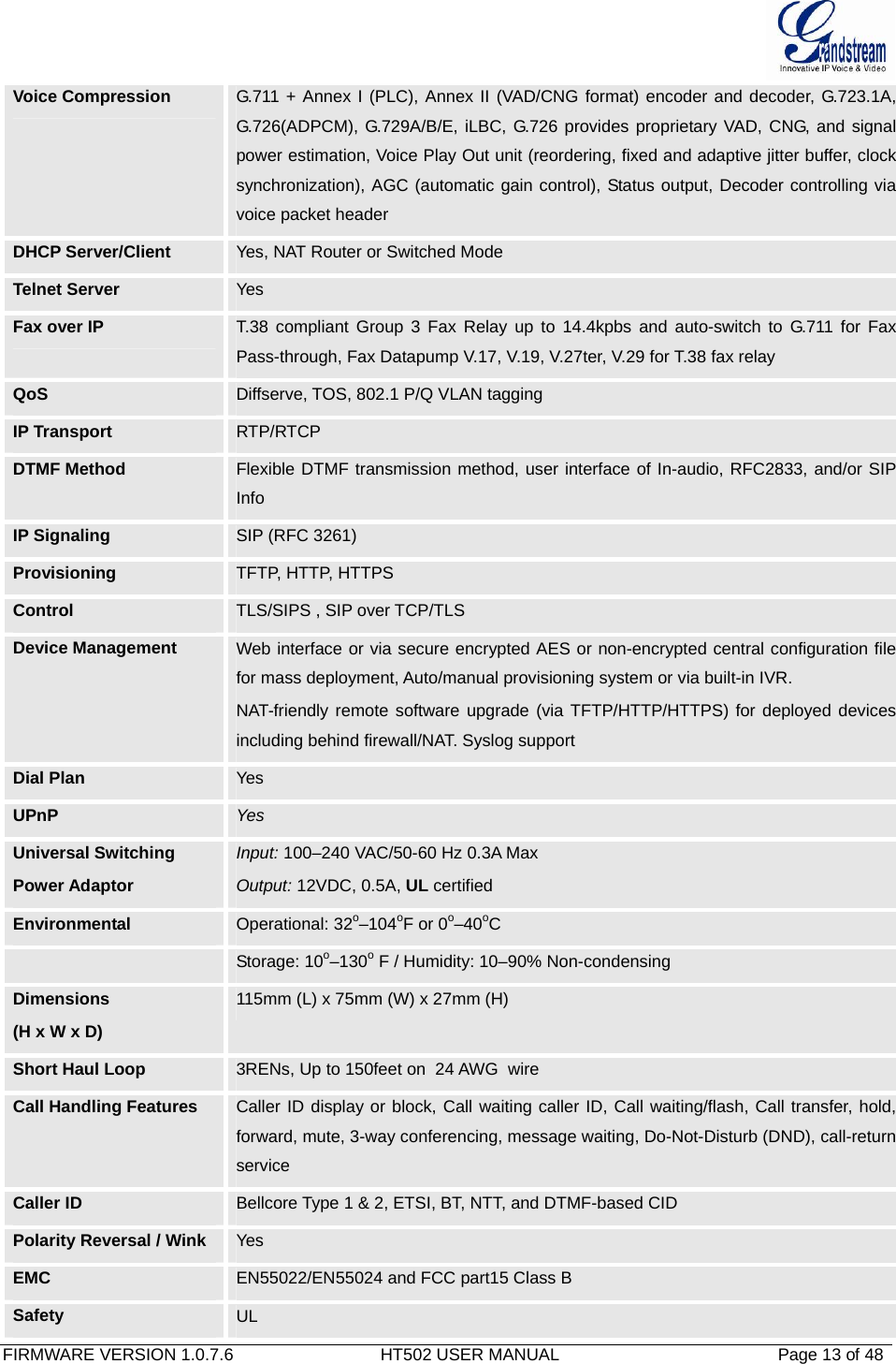
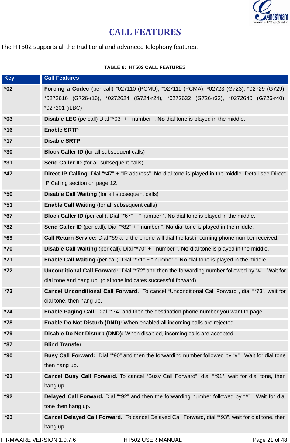

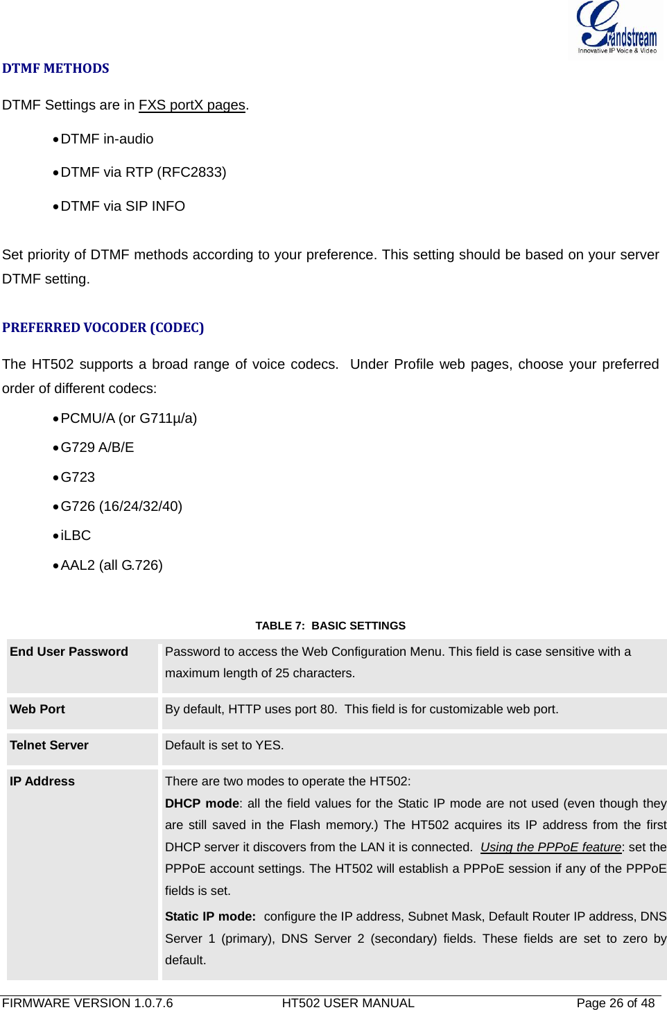
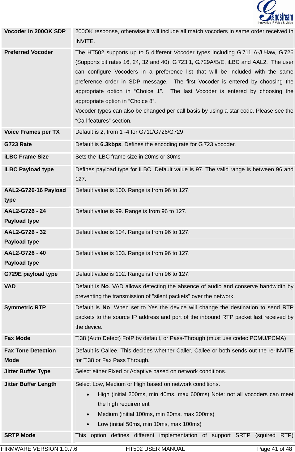
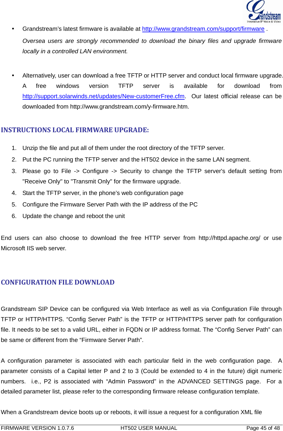
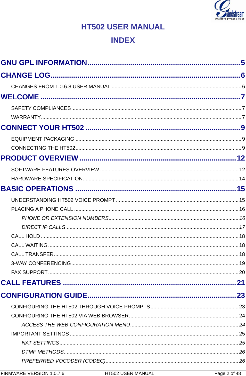
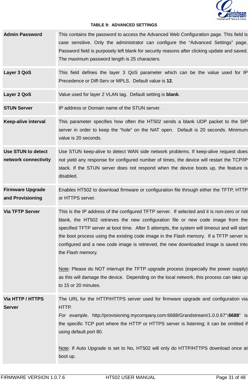
![FIRMWARE VERSION 1.0.7.6 HT502 USER MANUAL Page 27 of 48 DHCP hostname Default is blank. This option specifies the name of the client. This field is optional but may be required by some Internet Service Providers. DHCP vendor class ID Default is HT500. Used by clients and servers to exchange vendor-specific information.. PPPoE account ID PPPoE username. Necessary if ISP requires you to use a PPPoE (Point to Point Protocol over Ethernet) connection. PPPoE password PPPoE account password. PPPoE Service Name Default is blank. This field is optional. If your ISP uses a service name for the PPPoE connection, enter the service name here. Time Zone Controls how the date/time is displayed according to the specified time zone. Self Defined Time Zone The syntax is std offset dst [offset],start[/time],end[/time] Default is set to : MTZ+6MDT+5,M3.2.0,M11.1.0 MTZ+6MDT+5, Time zone with 6 hours offset with 1 hour ahead which is the US central time. It is positive (+) if the local time zone is west of the Prime Meridian and negative (-) if it is east. Prime Meridian (a.k.a: International or Greenwich Meridian) M3.2.0,M11.1.0 The 1st number indicates Month: 1,2,3,..,12 (for Jan, Feb, .., Dec) The 2nd number indicates the nth iteration of the weekday: (1st Sunday, 3rd Tuesday etc) The 3rd number indicates Weekday: 0,1, 2, ..,6(for Sun, Mon, Tue, .., Sat) Therefore, this example is the DST which starts from the second Sunday of March to the 1st Sunday of November. Language Languages supported with voice prompt and web interface, except Spanish that it is only in IVR. Device Mode This parameter controls whether the device is working in NAT router mode or Bridge mode. Save the setting and reboot prior to configuring HT502. NAT Maximum Ports The number of ports that can be managed while in NAT router mode. Range: 0 – 4096, default is 1024. Typically one port per connection. NAT TCP Timeout NAT TCP idle timeout in seconds. Connection will be closed after preconfigured, timeout if not refreshed. Range: 0 - 3600 NAT UDP Timeout NAT TCP idle timeout in seconds. Connection will be closed after preconfigured, timeout if not refreshed. Range: 0 – 3600, default is 300](https://usermanual.wiki/Grandstream-Networks/HT502V2X/User-Guide-1842884-Page-27.png)
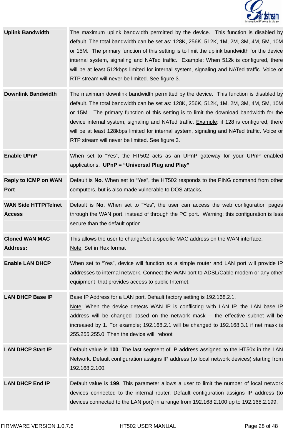
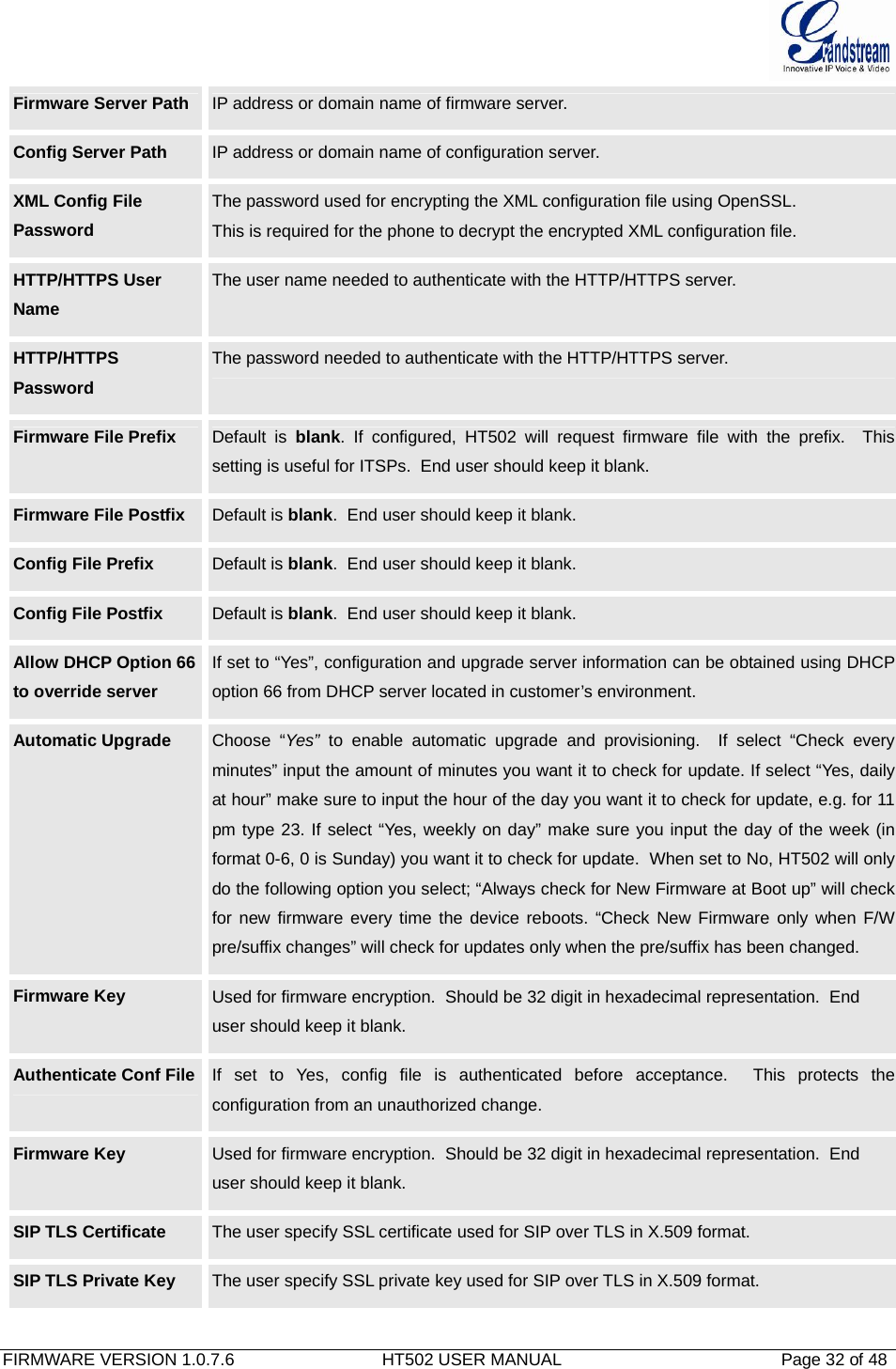
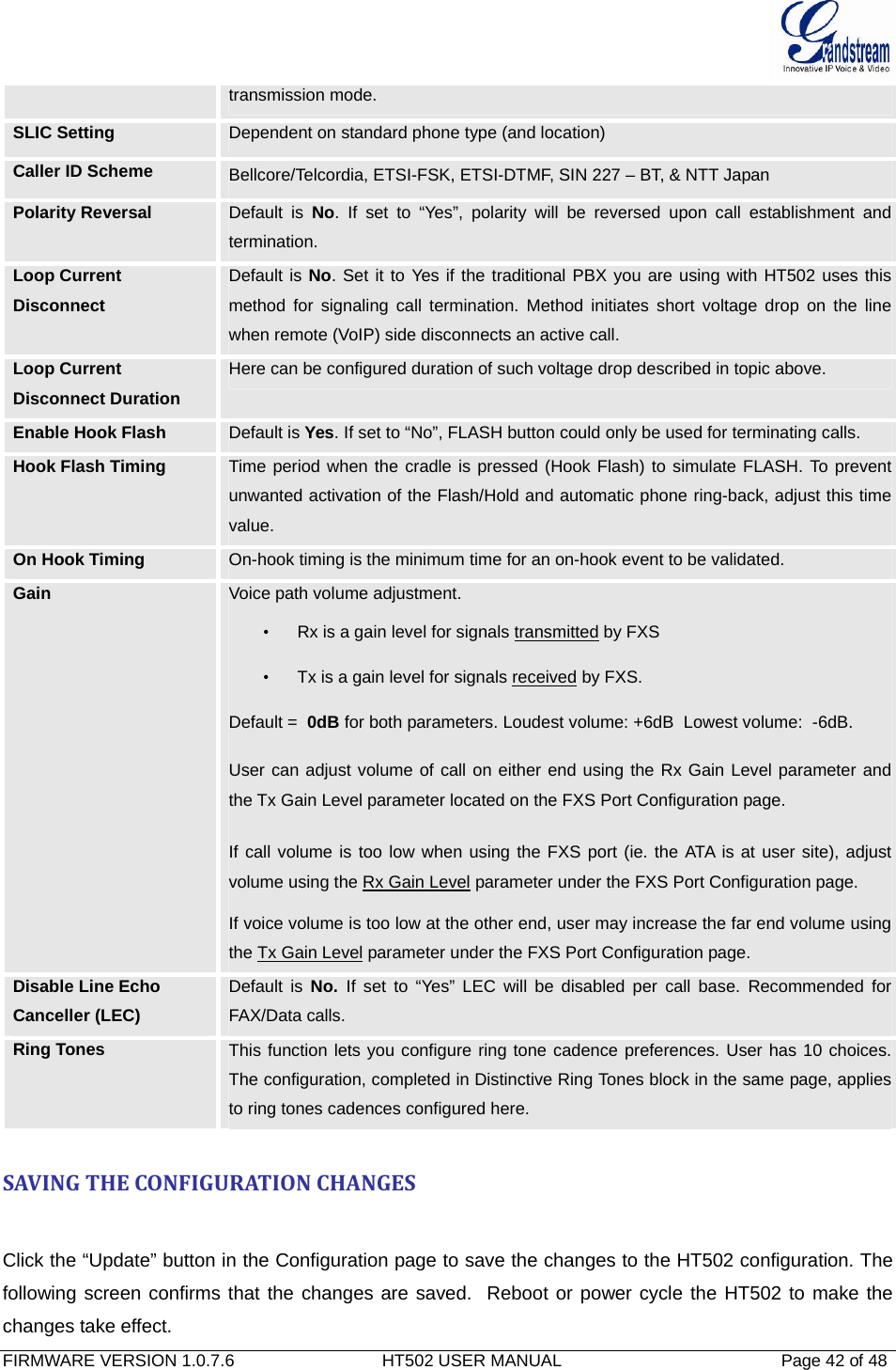
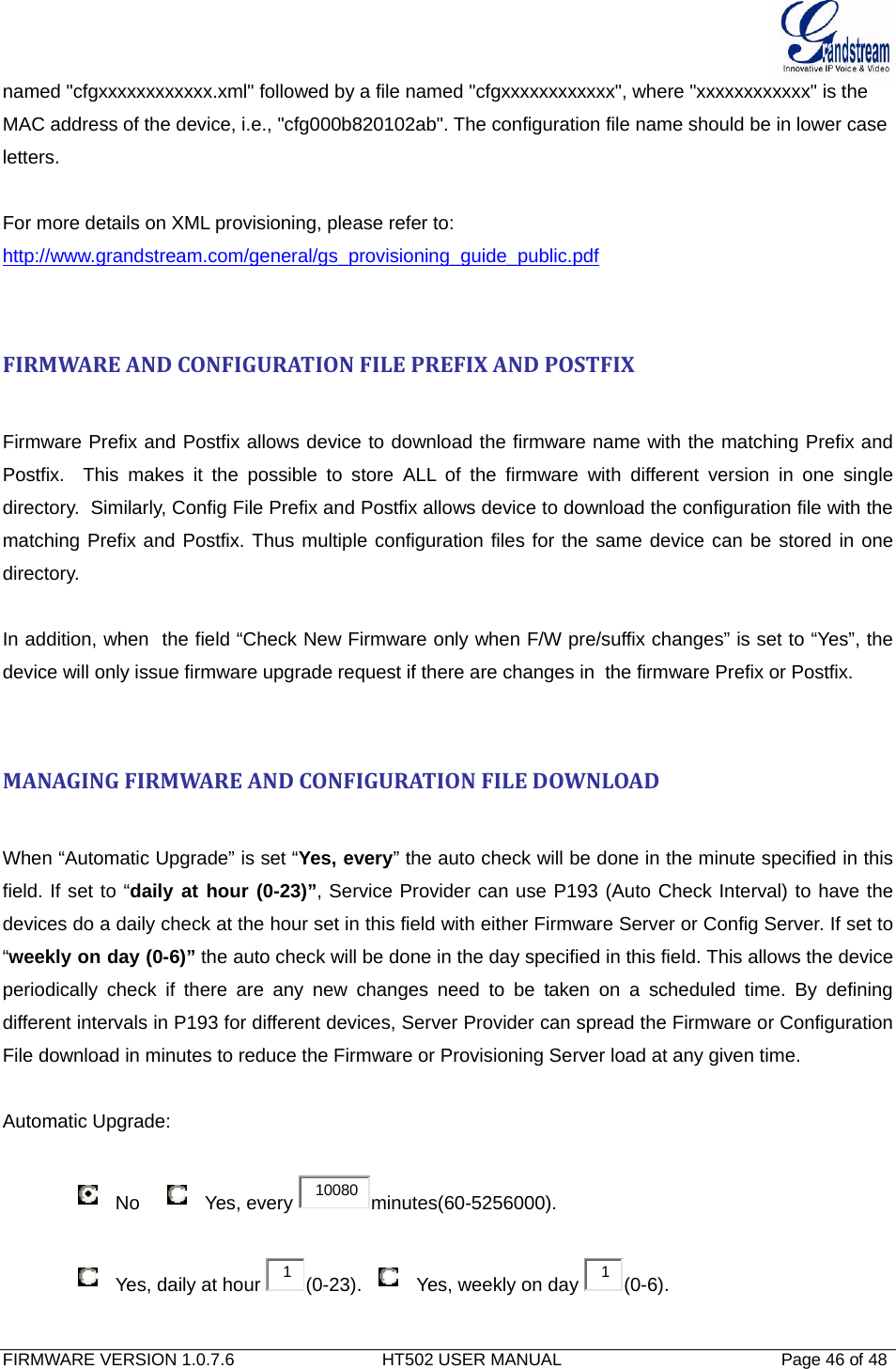
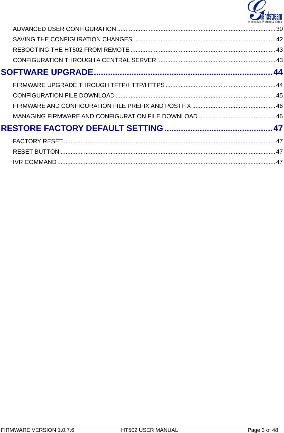
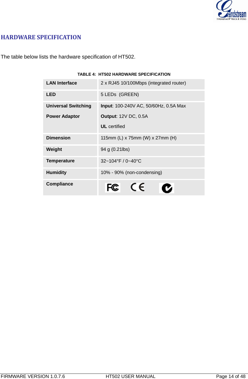
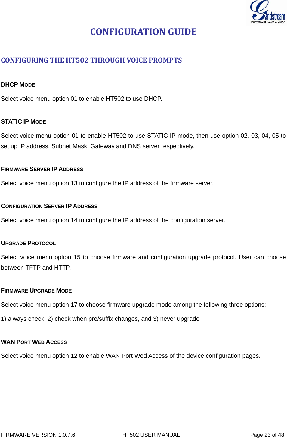
![FIRMWARE VERSION 1.0.7.6 HT502 USER MANUAL Page 33 of 48 SIP TLS Private Key Password User specify password to protect the private key above. ACS URL User specify the Auto Configuration Server’s URL (TR-069 protocol) ACS Username User specify the ACS Username ACS Password User specify the ACS password Periodic Inform Enable Default is No. If set to YES, device will send inform packets to the ACS Periodic Inform Interval Frequency that the inform packets will be sent out to the ACS Connection Request Username Set a user name for the ACS to connect to this device Connection Request Password Set a password for the ACS to connect to this device Connection Request Port Set a port number for the ACS to connect to this device, default is 7547 CPE SSL Certificate Configure the SSL authentication of Customer-premises equipment CPE SSL Private Key Configure the SSL Private Key of Customer-premises equipment System Ring Cadence Configuration option is set ring cadence on all FXS ports for all incoming calls. (Syntax: c=on1/off1-on2/off2-on3/off3(only 3 cadences maximum)) Default is set to c=2000/4000; (US standards) Call Progress Tones Using these settings, users can configure tone frequencies and cadence according to their preference. By default they are set to North American frequencies. Configure these settings with known values to avoid uncomfortable high pitch sounds. ON is the period of ringing (“On time” in ‘ms’) while OFF is the period of silence. In order to set a continuous tone, OFF should be zero. Otherwise it will ring ON ms and a pause of OFF ms and then repeat the pattern. Example configuration for N.A. Dialtone: f1=350@-13,f2=440@-13,c=0/0; Syntax: f1=freq@vol, f2=freq@vol, c=on1/off1-on2/off2-on3/off3; [...] (Note: freq: 0 - 4000Hz; vol: -30 - 0dBm)](https://usermanual.wiki/Grandstream-Networks/HT502V2X/User-Guide-1842884-Page-33.png)
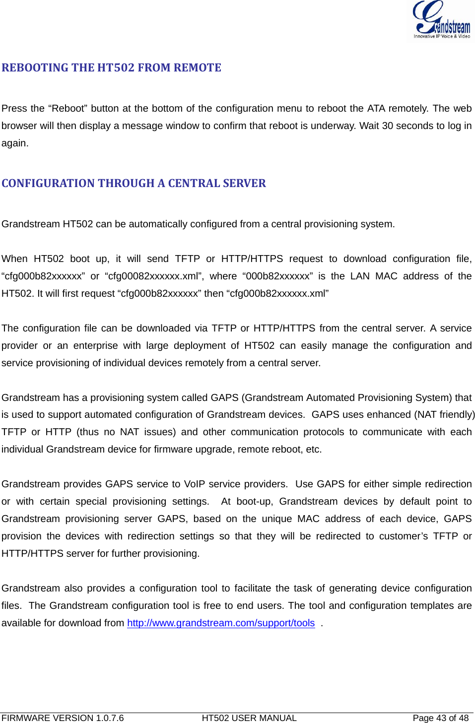
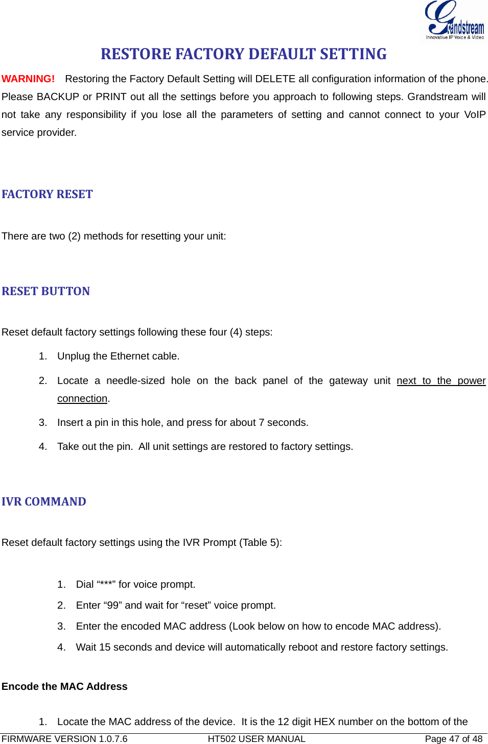
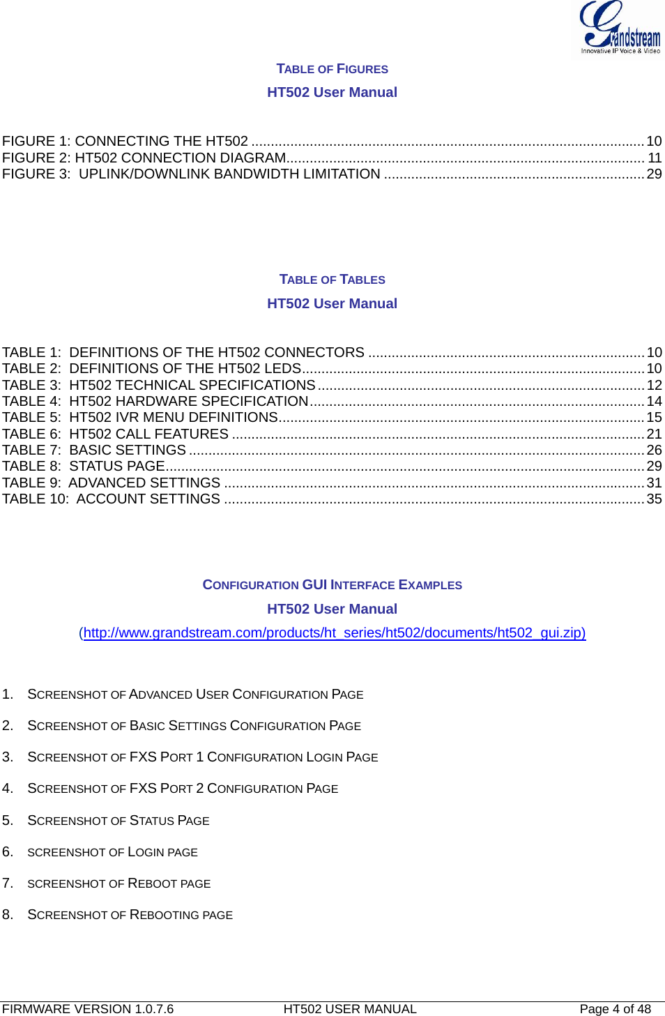
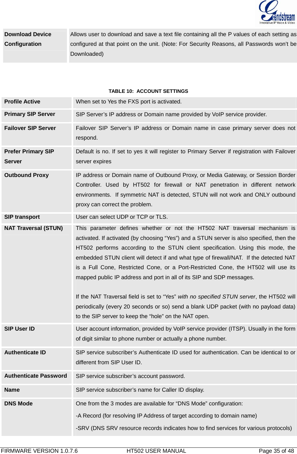
![FIRMWARE VERSION 1.0.7.6 HT502 USER MANUAL Page 34 of 48 Prompt Tone Access Code Key pattern to get Prompt Tone. Maximum 20 digits. No Default. Lock Keypad Update If set to “Yes”, the configuration update via keypad is disabled. Disable Voice Prompt Default is No. Disables the voice prompt configuration. Disable Direct IP Call Default is No. Disables the Direct IP Call function. NTP server URI or IP address of the NTP (Network Time Protocol) server. This parameter synchronizes the date and time. NTP Update Interval Updates the Network Time Protocol (Values range from 5 – 1440 minutes) Syslog Server The IP address or URL of System log server. This feature is especially useful for the ITSP (Internet Telephone Service Provider) Syslog Level Select the HT502 to report the log level. Default is NONE. The level is one of DEBUG, INFO, WARNING or ERROR. Syslog messages are sent based on the following events: 1. product model/version on boot up (INFO level) 2. NAT related info (INFO level) 3. sent or received SIP message (DEBUG level) 4. SIP message summary (INFO level) 5. inbound and outbound calls (INFO level) 6. registration status change (INFO level) 7. negotiated codec (INFO level) 8. Ethernet link up (INFO level) 9. SLIC chip exception (WARNING and ERROR levels) 10. memory exception (ERROR level) The Syslog uses USER facility. In addition to standard Syslog payload, it contains the following components: GS_LOG: [device MAC address][error code] error message Example: May 19 02:40:38 192.168.1.14 GS_LOG: [00:0b:82:00:a1:be][000] Ethernet link is up Send SIP Log If Syslog is enabled and Send SIP Log is set to YES, then SIP messages will also be delivered via Syslog. Default is set to NO.](https://usermanual.wiki/Grandstream-Networks/HT502V2X/User-Guide-1842884-Page-34.png)
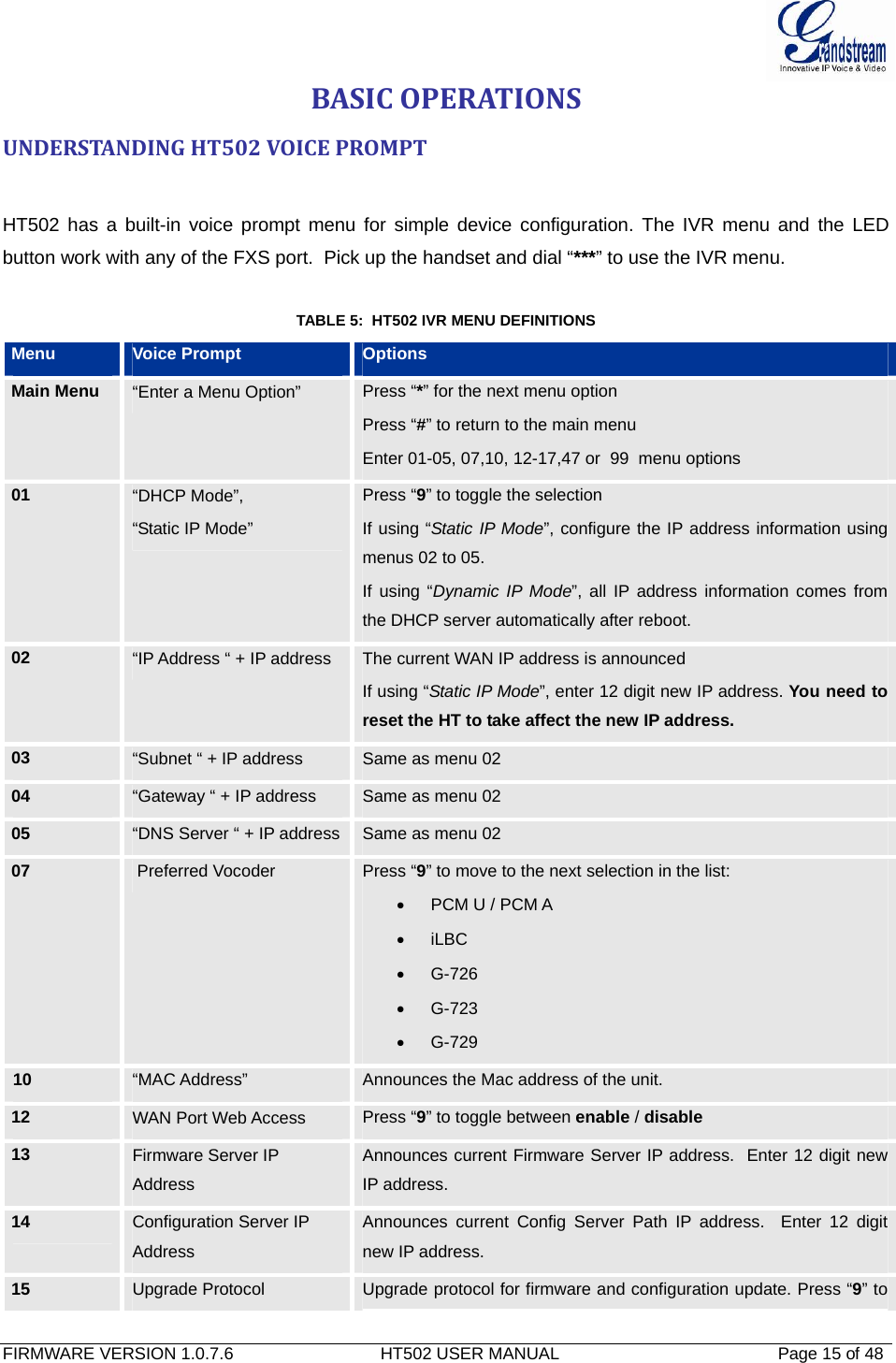
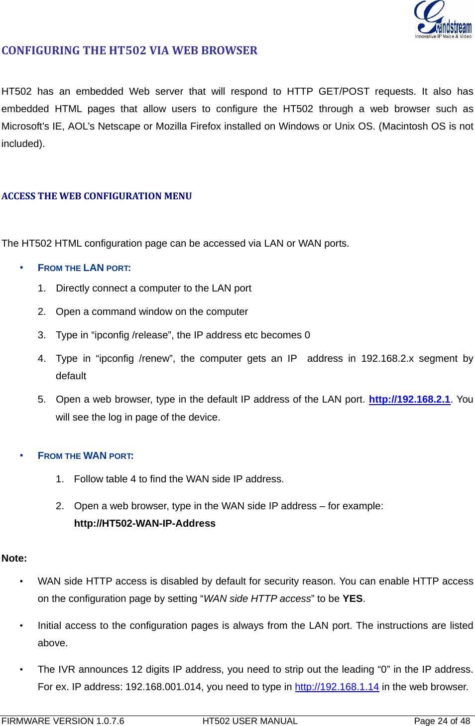
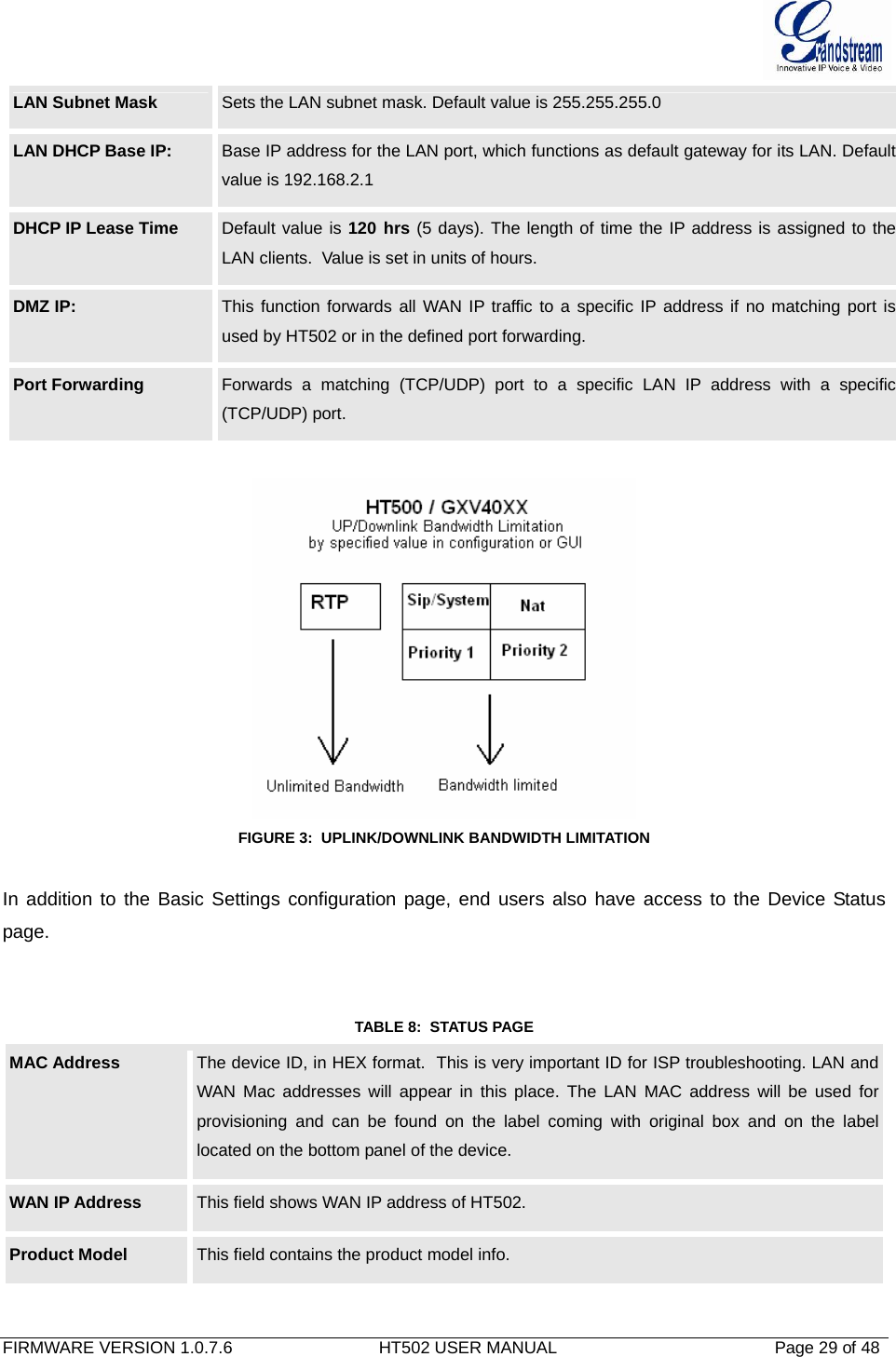
![FIRMWARE VERSION 1.0.7.6 HT502 USER MANUAL Page 39 of 48 Use # as Dial Key Allows users to configure the “#” key as the “Send” (or “Dial”) key. If set to “Yes”, “#” will send the number. In this case, this key is essentially equivalent to the “Dial” key. If set to “No”, this “#” key can be included as part of number. Dial Plan Dial Plan Rules: 1. Accept Digits: 1,2,3,4,5,6,7,8,9,0 , *, #, A,a,B,b,C,c,D,d 2. Grammar: x - any digit from 0-9; • xx+ - at least 2 digits number; • xx. – at least 2 digit number. • ^ - exclude; • [3-5] - any digit of 3, 4, or 5; • [147] - any digit 1, 4, or 7; • <2=011> - replace digit 2 with 011 when dialing • < =1> - add a leading 1 to all numbers dialed, vice versa will remove a 1 from the number dialed • | - or • Example 1: {[369]11 | 1617xxxxxxx} – Allow 311, 611, 911, and any 11 digit numbers with leading digits 1617 Example 2: {^1900x+ | <=1617>xxxxxxx} – Block any number of leading digits 1900 and add prefix 1617 for any dialed 7 digit numbers • Example 3: {1xxx[2-9]xxxxxx | <2=011>x+} –Allow any combinations of numbers with 11 digits which has a leading digit 1, but 5th digit cannot be 0 or 1. Or any length of numbers with a minimum of 2 digits beginning with 2, with the leading digit replaced with 011. 3. Default: Outgoing - {x+} Example of a simple dial plan used in a Home/Office in the US: { ^1900x. | <=1617>[2-9]xxxxxx | 1[2-9]xx[2-9]xxxxxx | 011[2-9]x. | [3469]11 } Explanation of example rule (reading from left to right): • ^1900x. - prevents dialing any number started with 1900 • <=1617>[2-9]xxxxxx - allows dialing to local area code (617) numbers by dialing 7 numbers and 1617 area code will be added automatically • 1[2-9]xx[2-9]xxxxxx |- allows dialing to any US/Canada Number with 11 digits length • 011[2-9]x. - allows international calls starting with 011 • [3469]11 - allow dialing special and emergency numbers 311, 411, 611 and 911 Note: In some cases user wishes to dial strings such as *123 to activate voice mail or other application provided by service provider. In this case * should be predefined](https://usermanual.wiki/Grandstream-Networks/HT502V2X/User-Guide-1842884-Page-39.png)