Grandstream Networks HT802 Analog Telephone Adaptor User Manual
Grandstream Networks, Inc Analog Telephone Adaptor
UserManual.wiki
>
Grandstream Networks
>
HT802 User Manual
User Manual
Navigation menu
Upload a User Manual
Namespaces
Wiki Guide
HTML
PDF
Info
Views
User Manual
Discussion / Help
Navigation

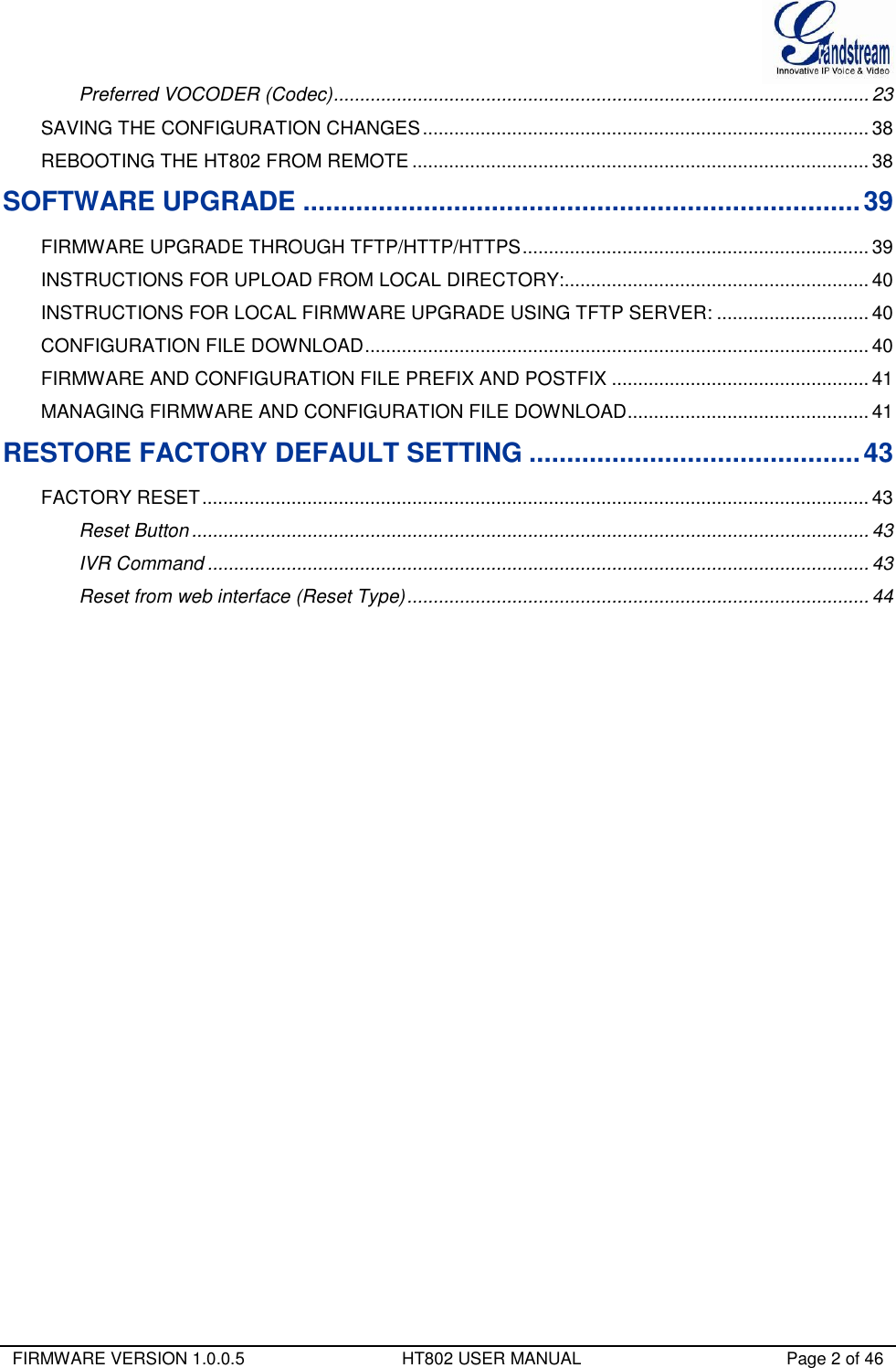

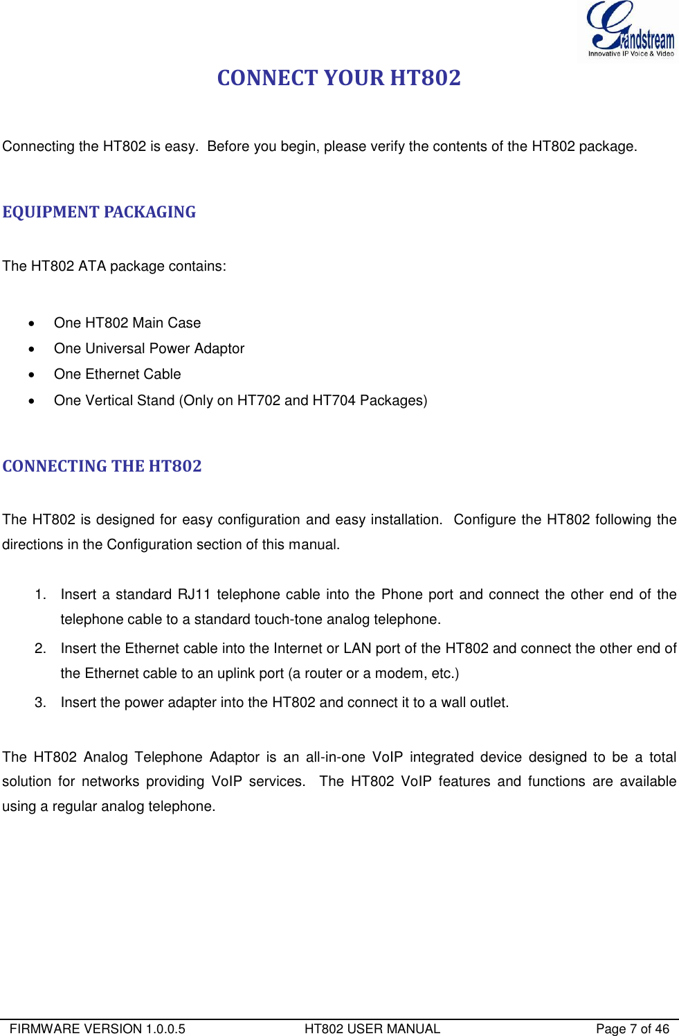

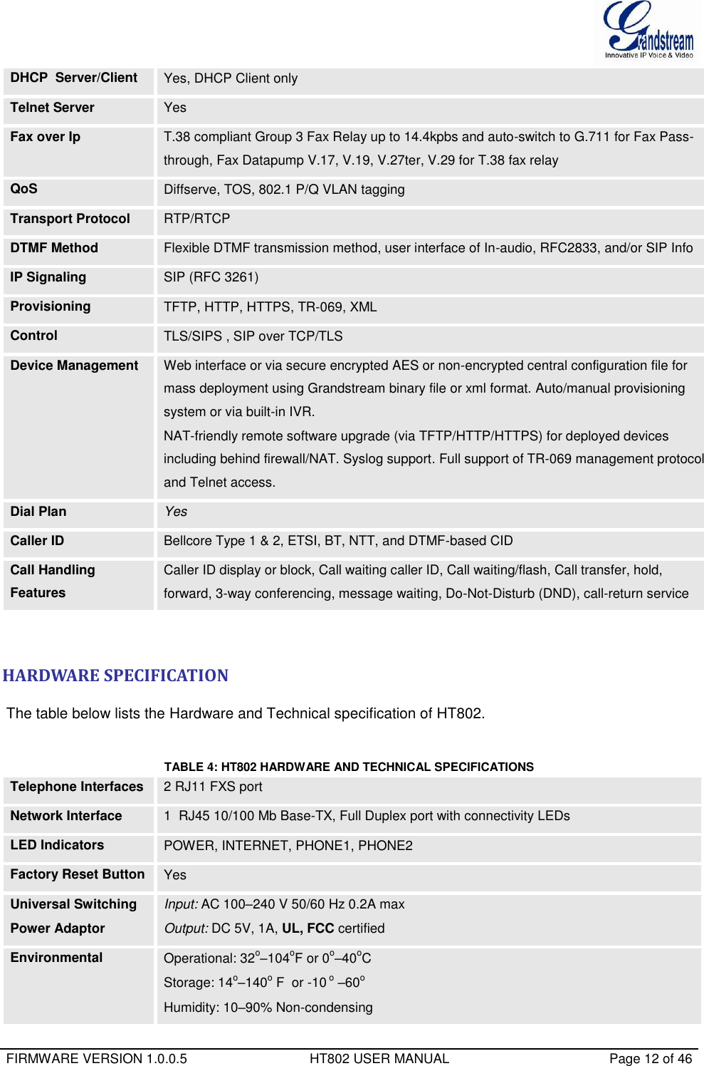
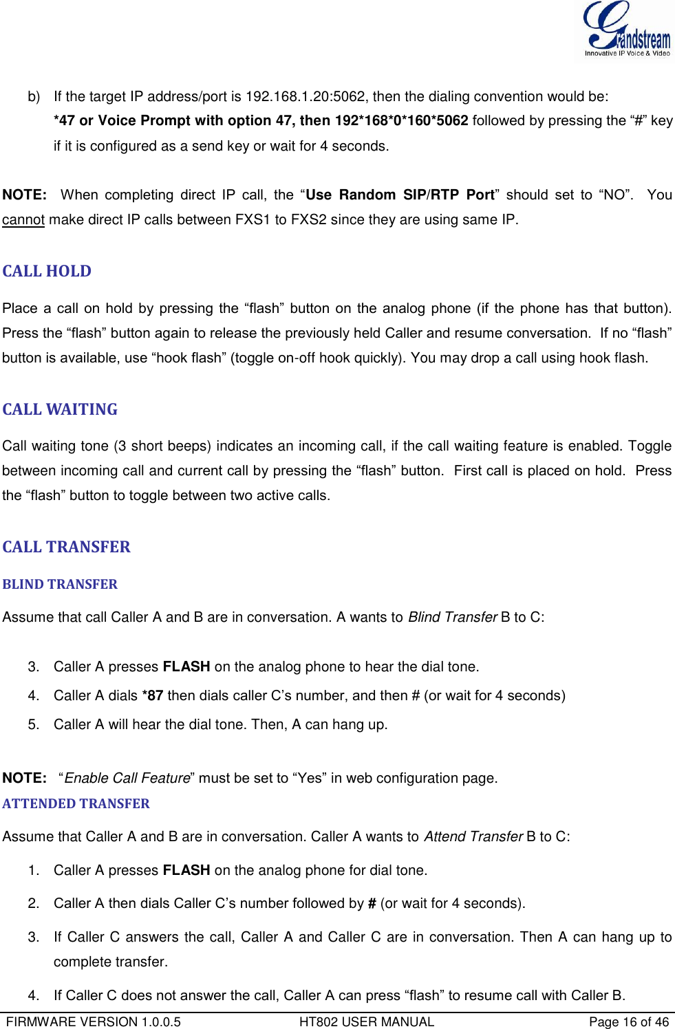


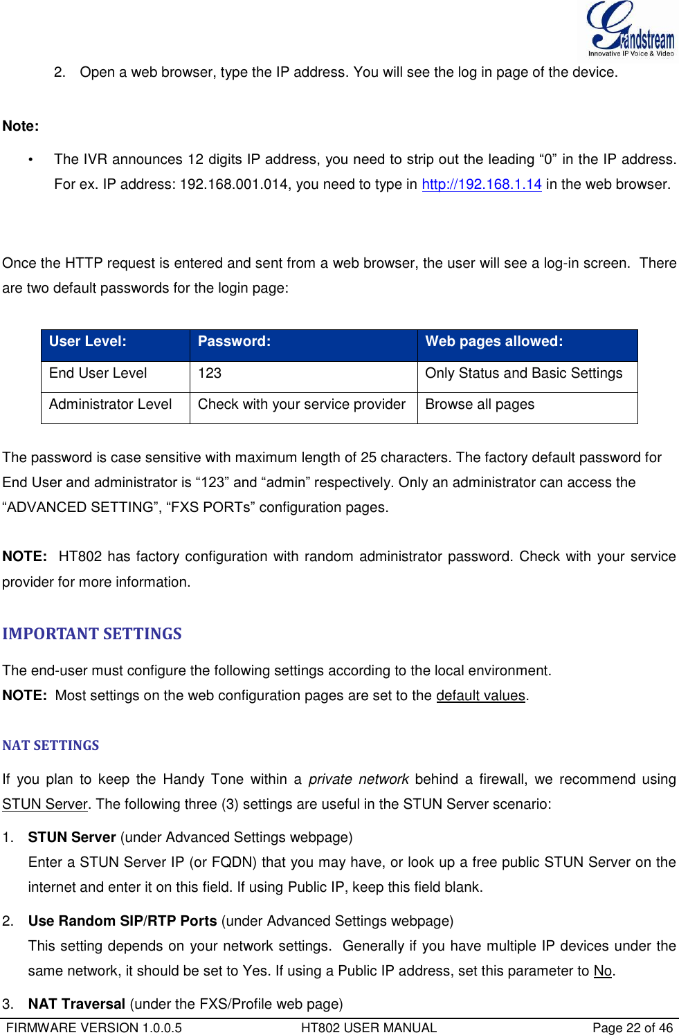
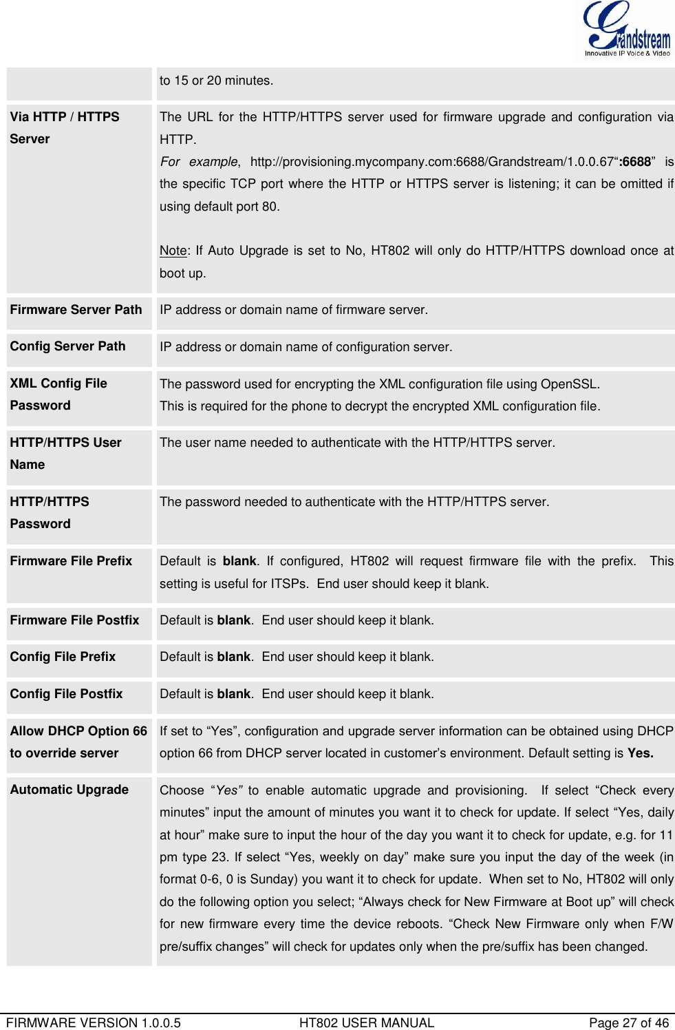
![FIRMWARE VERSION 1.0.0.5 HT802 USER MANUAL Page 24 of 46 DHCP vendor class ID Default is HT7XX. Used by clients and servers to exchange vendor-specific information.. Time Zone Controls how the date/time is displayed according to the specified time zone. Self-Defined Time Zone The syntax is std offset dst [offset],start[/time],end[/time] Default is set to : MTZ+6MDT+5,M3.2.0,M11.1.0 MTZ+6MDT+5, Time zone with 6 hours offset with 1 hour ahead which is the US central time. It is positive (+) if the local time zone is west of the Prime Meridian and negative (-) if it is east. Prime Meridian (a.k.a: International or Greenwich Meridian) M3.2.0,M11.1.0 The 1st number indicates Month: 1,2,3,..,12 (for Jan, Feb, .., Dec) The 2nd number indicates the nth iteration of the weekday: (1st Sunday, 3rd Tuesday etc) The 3rd number indicates Weekday: 0,1, 2, ..,6(for Sun, Mon, Tue, .., Sat) Therefore, this example is the DST which starts from the second Sunday of March to the 1st Sunday of November. Allow DHCP server to set Time Zone Default Yes. Let the DHCP server handle the Time Zone Language Languages supported with voice prompt and web interface, except Spanish that it is only in IVR. Reset Type Gives the user the option to set to default all VoIP related configuration (mainly everything located on FXS/Profile page), all ISP (Internet Service Provider) configuration which may affect the IP address, or both at the same time. Note: After you choose the reset type, you will have to click the reset button for it to take effect. In addition to the Basic Settings configuration page, end users also have access to the Device Status page. TABLE 8: STATUS PAGE MAC Address The device ID, in HEX format. This is very important ID for ISP troubleshooting. The Mac address will appear in this place. The MAC address will be used for provisioning and can be found on the label coming with original box and on the label located on the bottom panel of the device.](https://usermanual.wiki/Grandstream-Networks/HT802/User-Guide-2486780-Page-26.png)
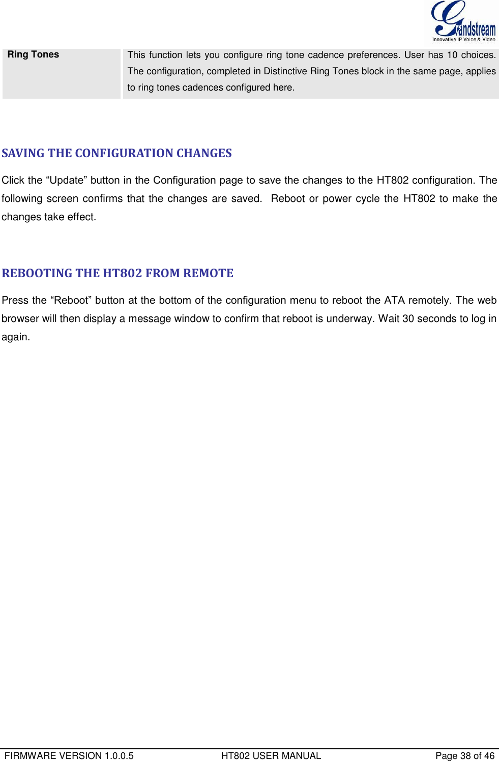
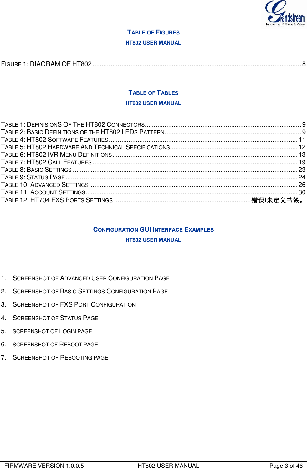
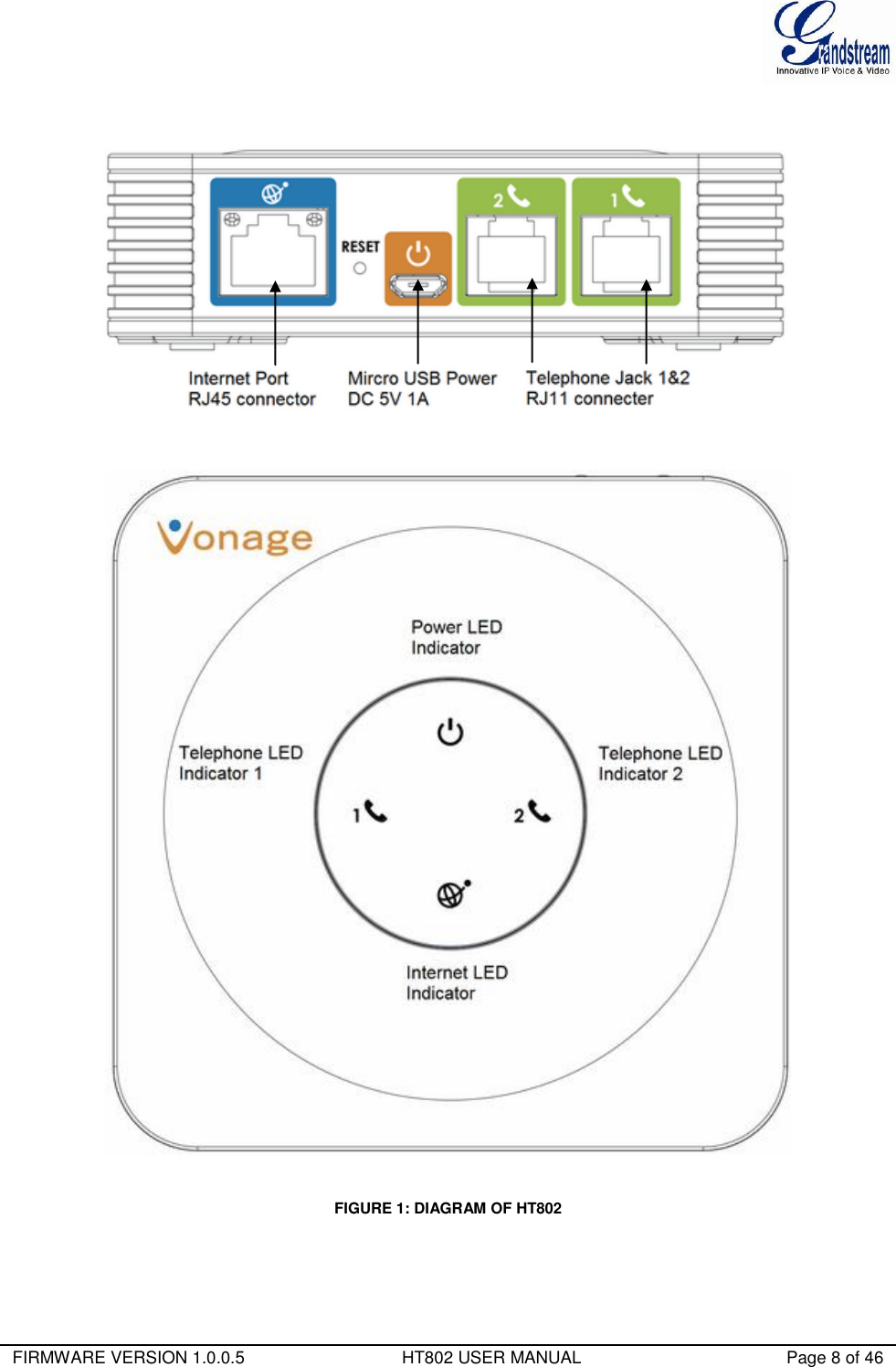
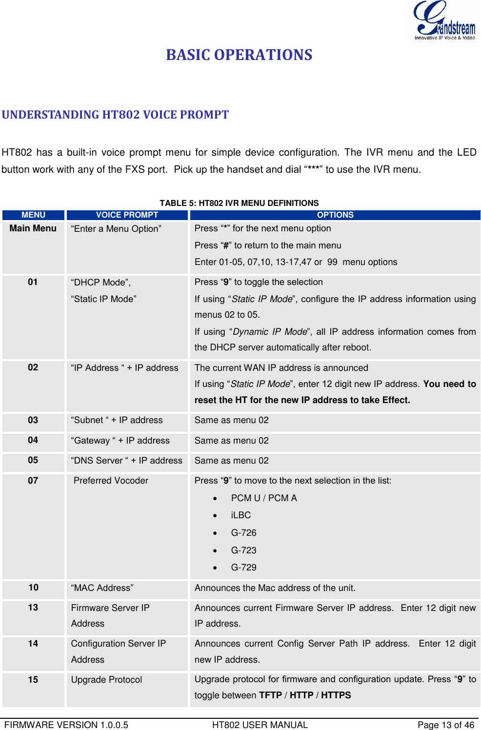
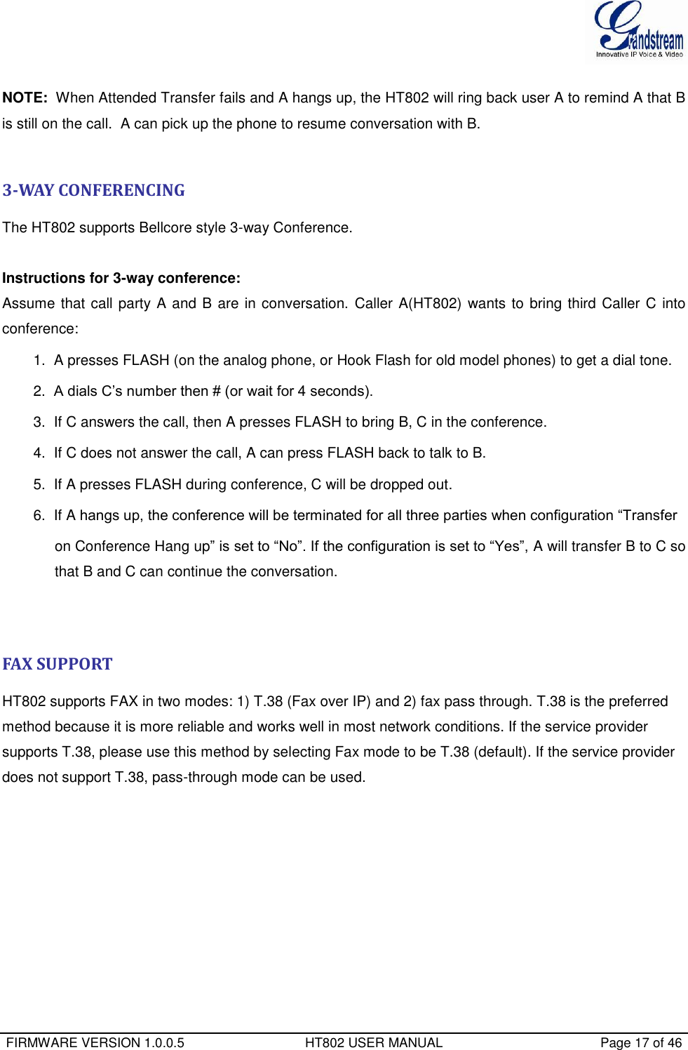
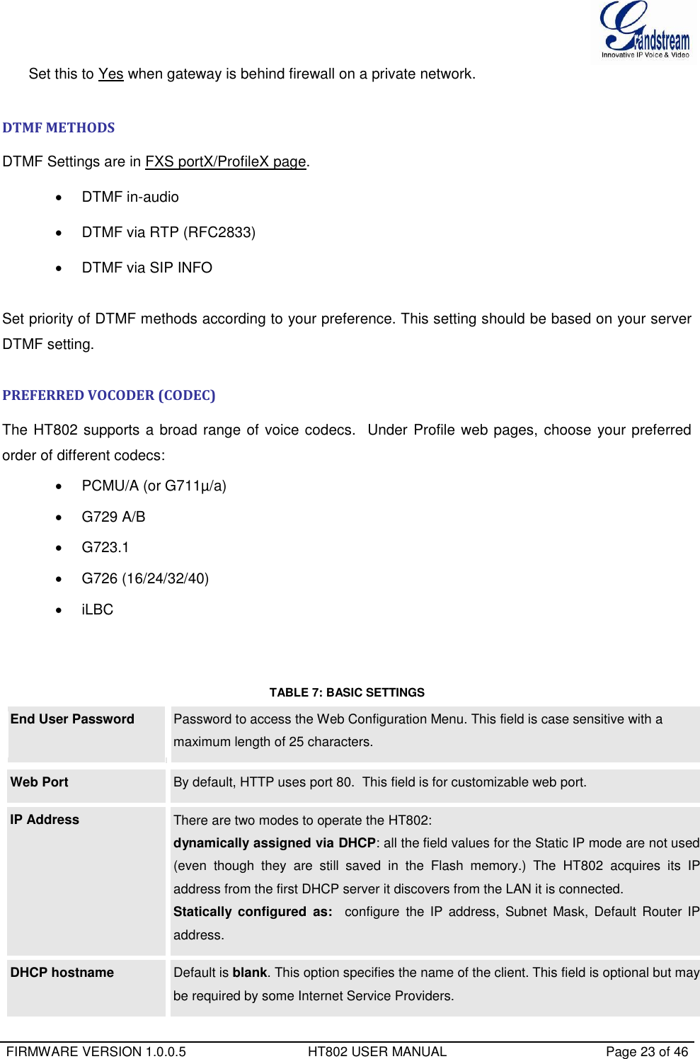
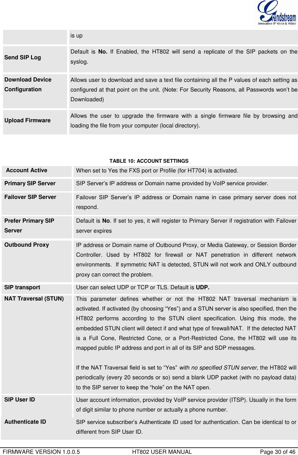
![FIRMWARE VERSION 1.0.0.5 HT802 USER MANUAL Page 28 of 46 Authenticate Conf File If set to Yes, config file is authenticated before acceptance. This protects the configuration from an unauthorized change. SIP TLS Certificate The user specify SSL certificate used for SIP over TLS in X.509 format. SIP TLS Private Key The user specify SSL private key used for SIP over TLS in X.509 format. SIP TLS Private Key Password User specify password to protect the private key above. ACS URL User specify the Auto Configuration Server’s URL (TR-069 protocol) ACS Username User specify the ACS Username ACS Password User specify the ACS password Periodic Inform Enable Default is No. If set to YES, device will send inform packets to the ACS Periodic Inform Interval Frequency that the inform packets will be sent out to the ACS Connection Request Username Set a user name for the ACS to connect to this device Connection Request Password Set a password for the ACS to connect to this device CPE SSL Certificate The Cert File for the phone to connect to the ACS via SSL. CPE SSL Private Key The Cert Key for the phone to connect to the ACS via SSL. System Ring Cadence Configuration option is set ring cadence on all FXS ports for all incoming calls. (Syntax: c=on1/off1-on2/off2-on3/off3(only 3 cadences maximum)) Default is set to c=2000/4000; (US standards) Call Progress Tones Using these settings, users can configure tone frequencies and cadence according to their preference. By default they are set to North American frequencies. Configure these settings with known values to avoid uncomfortable high pitch sounds. ON is the period of ringing (“On time” in ‘ms’) while OFF is the period of silence. In order to set a continuous tone, OFF should be zero. Otherwise it will ring ON ms and a pause of OFF ms and then repeat the pattern. Example configuration for N.A. Dialtone: f1=350@-13,f2=440@-13,c=0/0; Syntax: f1=freq@vol, f2=freq@vol, c=on1/off1-on2/off2-on3/off3; [...]](https://usermanual.wiki/Grandstream-Networks/HT802/User-Guide-2486780-Page-30.png)
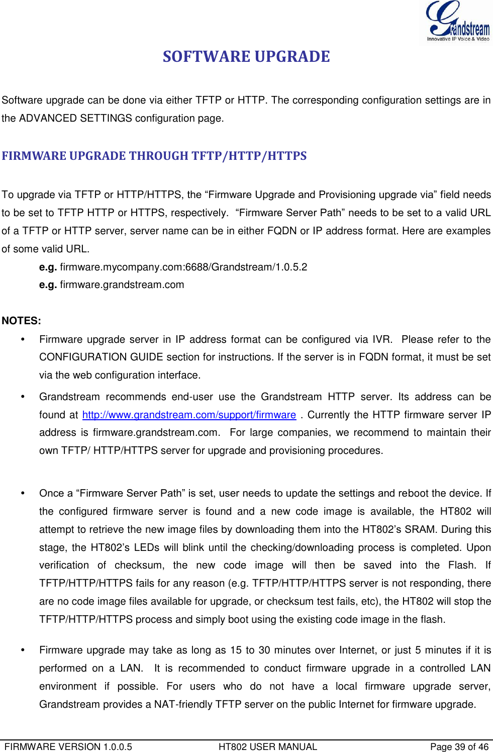
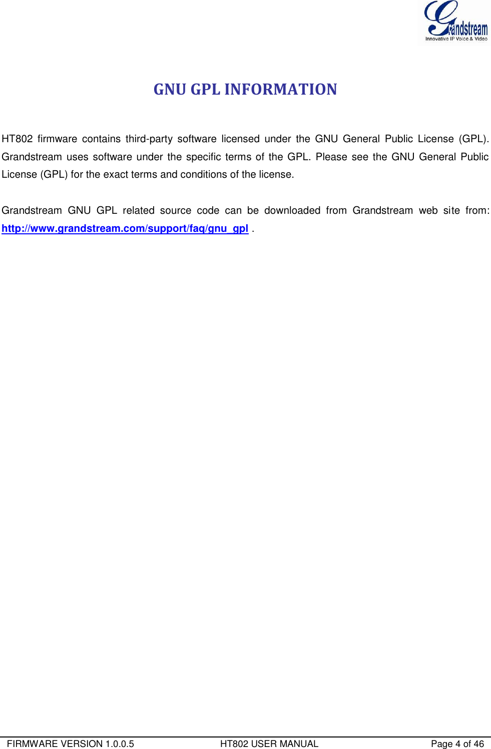
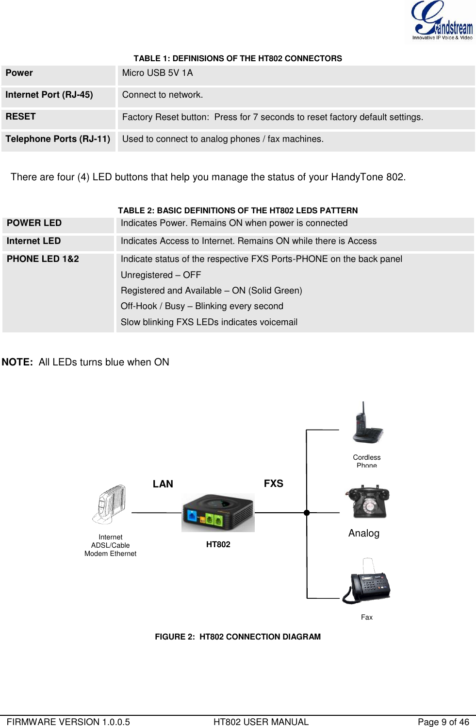
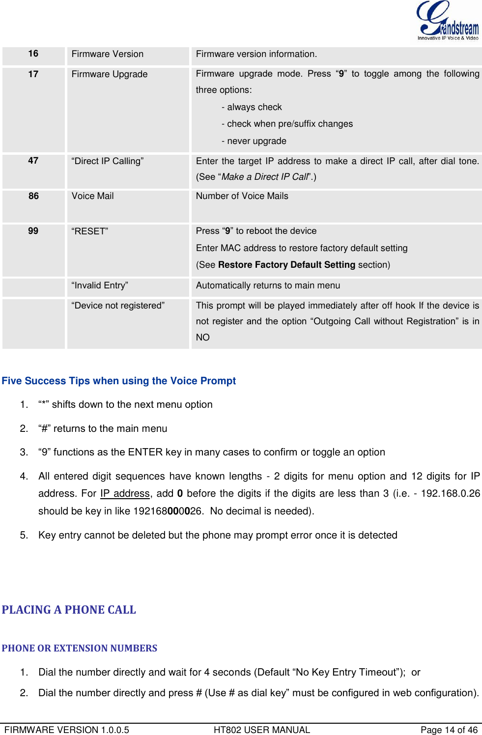
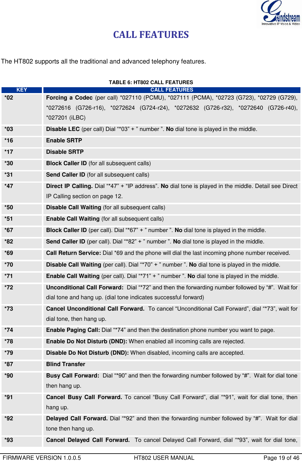
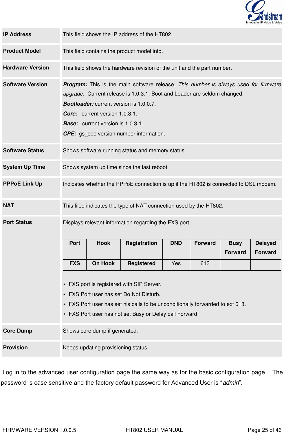
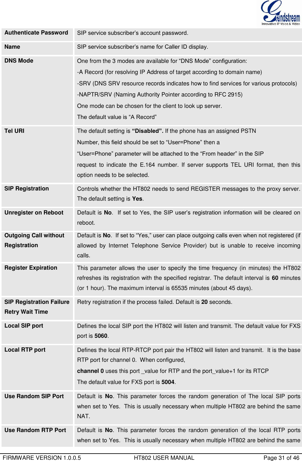
![FIRMWARE VERSION 1.0.0.5 HT802 USER MANUAL Page 29 of 46 (Note: freq: 0 - 4000Hz; vol: -30 - 0dBm) Feature Activation Codes (* or # followed by 1-5 digits) Blind Transfer Code: Custom the Blind Transfer Code (Default #90). Lock Keypad Update Default is No. If set to “Yes”, the configuration update via keypad is disabled. Disable Voice Prompt Default is No. Disables the voice prompt configuration. Disable Direct IP Call Default is No. Disables the Direct IP Call function. NTP server URI or IP address of the NTP (Network Time Protocol) server. This parameter synchronizes the date and time. Allow DHCP option 42 to override NTP serve Default Yes. Enables the DHCP server to handle the NTP Server via Option 42 Syslog Server The IP address or URL of System log server. This feature is especially useful for the ITSP (Internet Telephone Service Provider) Syslog Level Select the HT802 to report the log level. Default is NONE. The level is one of EXTRA DEBUG, DEBUG, INFO, WARNING or ERROR. Syslog messages are sent based on the following events: 1. product model/version on boot up (INFO level) 2. NAT related info (INFO level) 3. sent or received SIP message (DEBUG level) 4. SIP message summary (INFO level) 5. inbound and outbound calls (INFO level) 6. registration status change (INFO level) 7. negotiated codec (INFO level) 8. Ethernet link up (INFO level) 9. SLIC chip exception (WARNING and ERROR levels) 10. memory exception (ERROR level) 11. Vonage requested syslog style (EXTRA DEBUG level) The Syslog uses USER facility. In addition to standard Syslog payload, it contains the following components: GS_LOG: [device MAC address][error code] error message Example: May 19 02:40:38 192.168.1.14 GS_LOG: [00:0b:82:00:a1:be][000] Ethernet link](https://usermanual.wiki/Grandstream-Networks/HT802/User-Guide-2486780-Page-31.png)
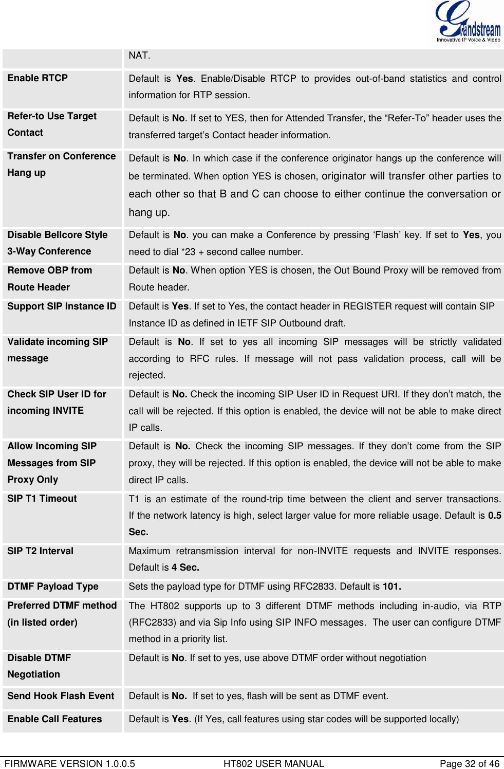
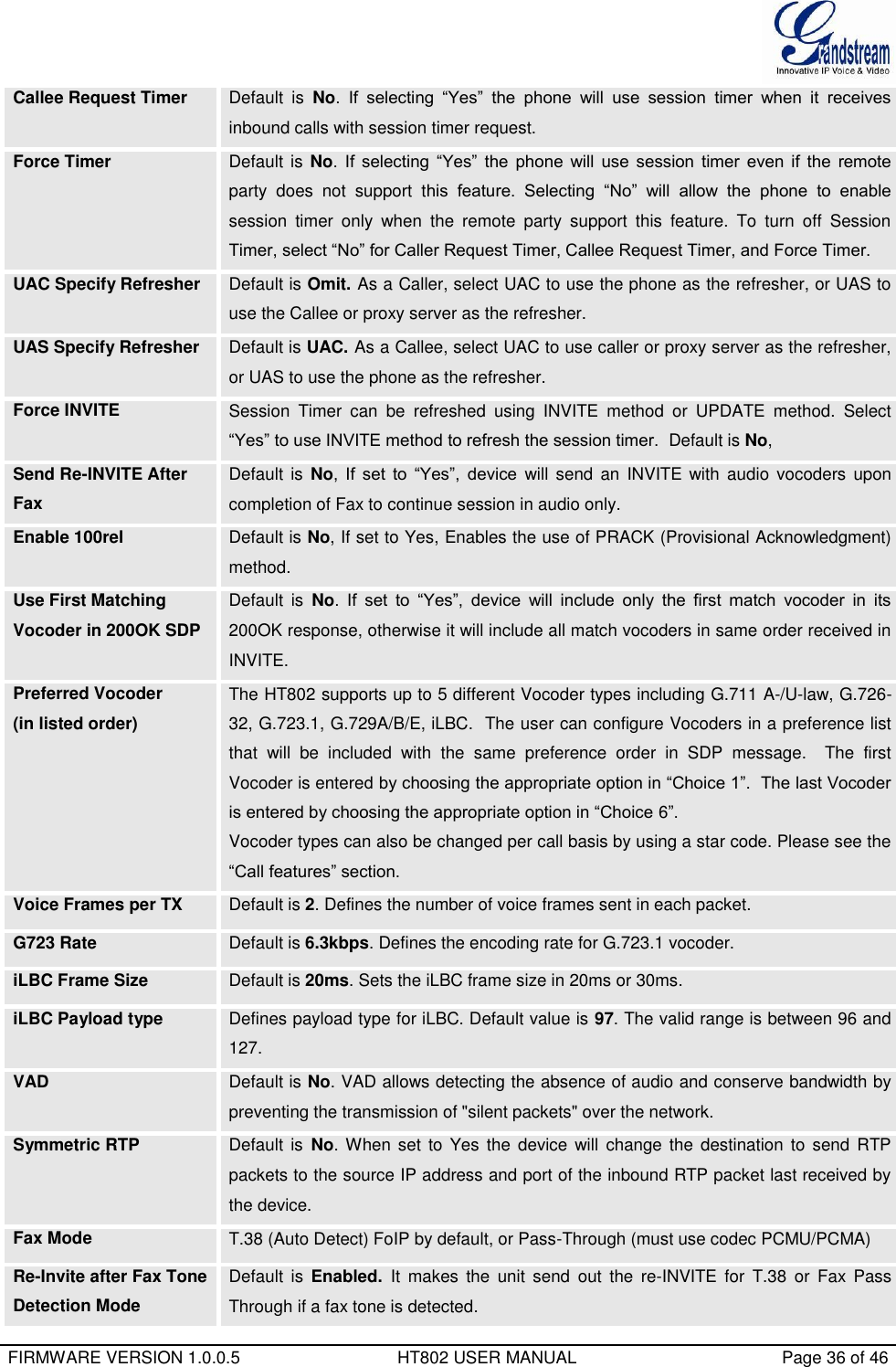
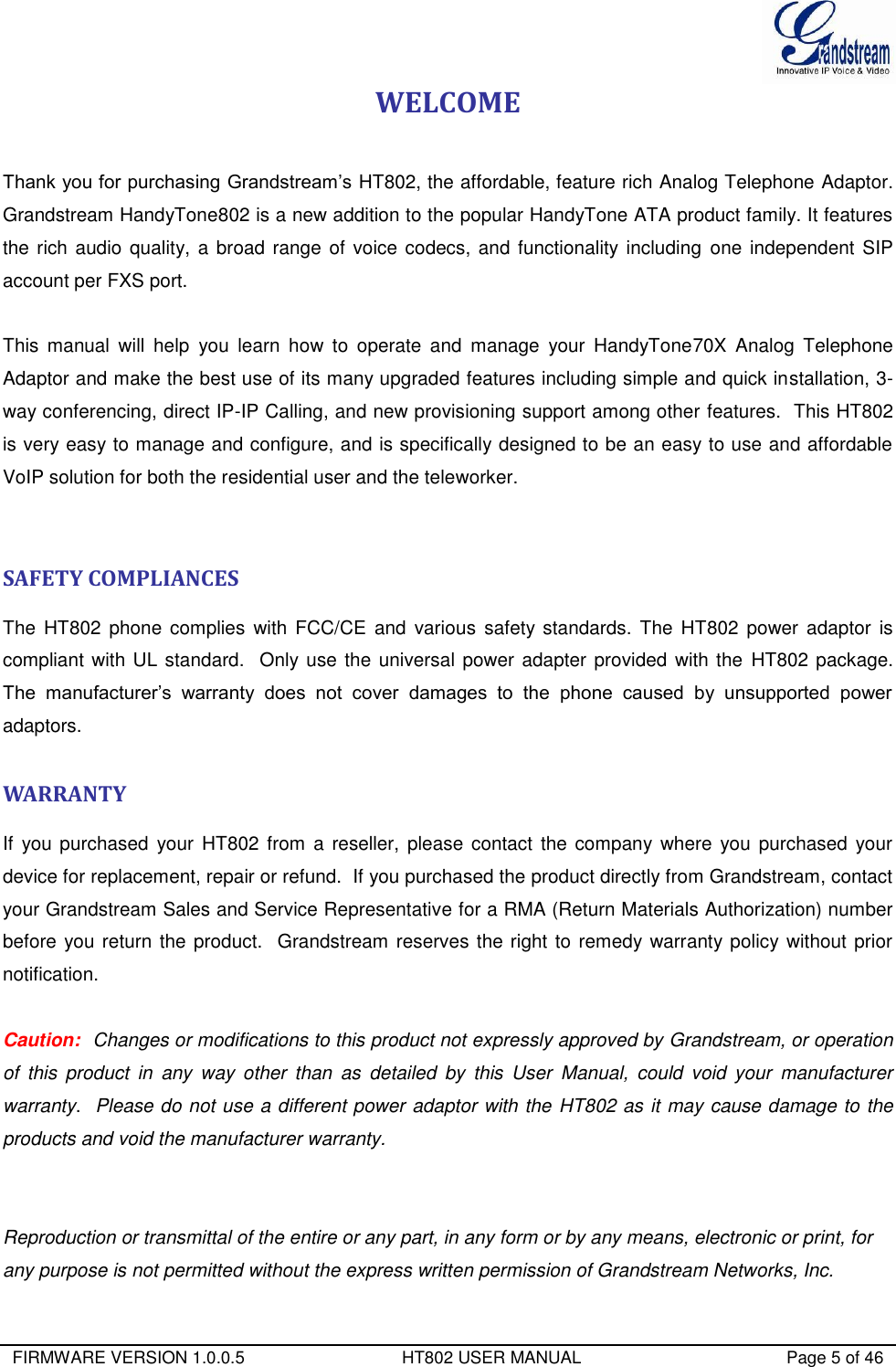
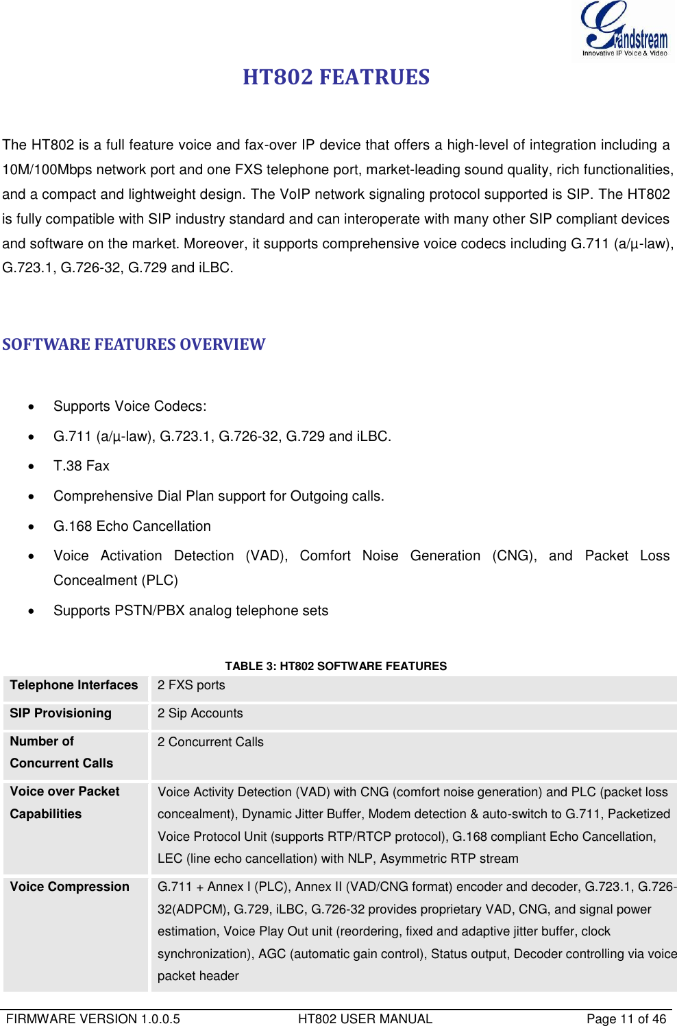
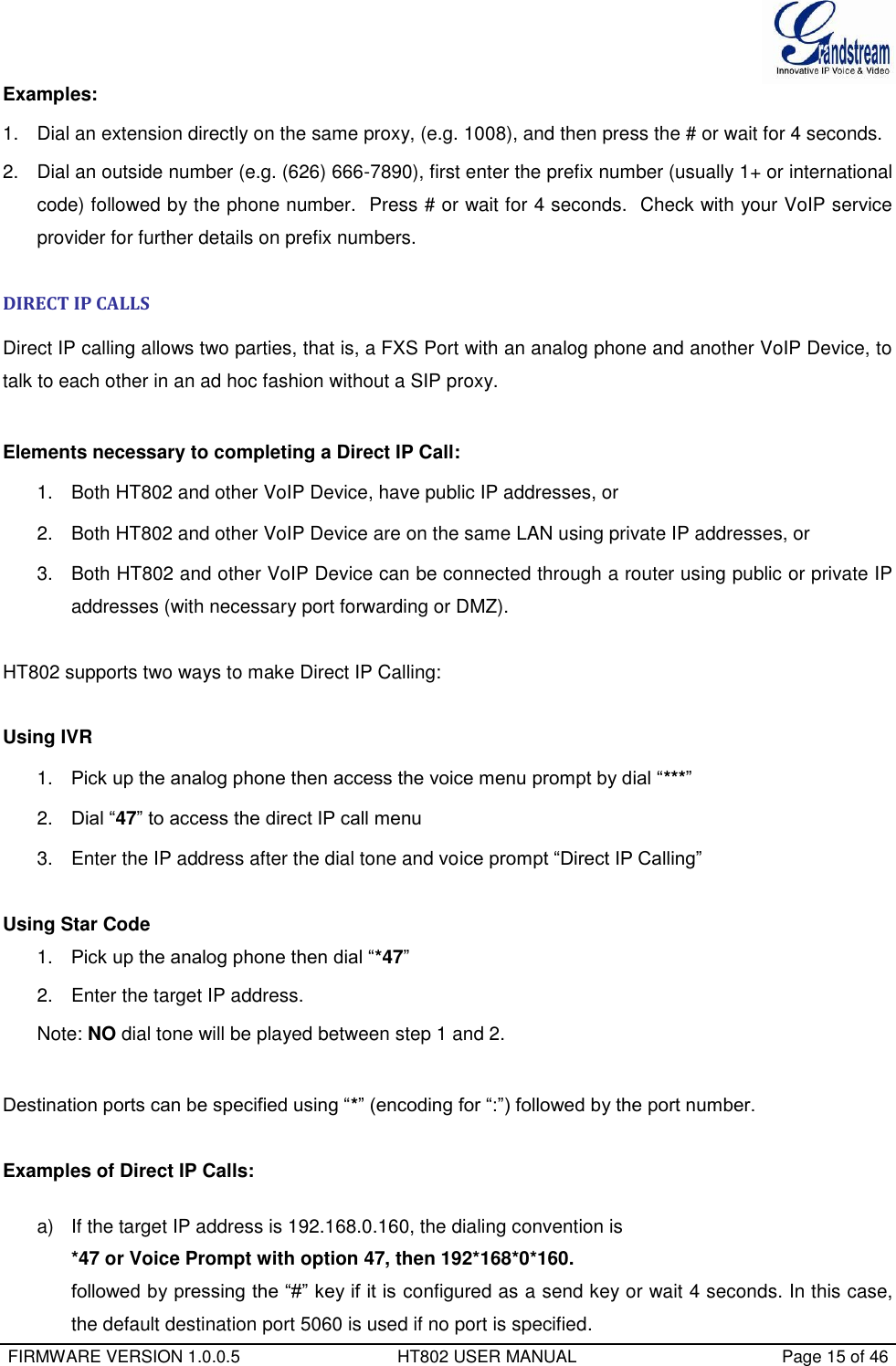
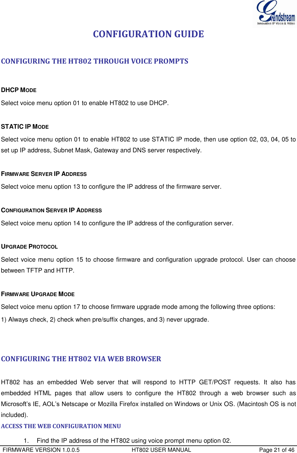
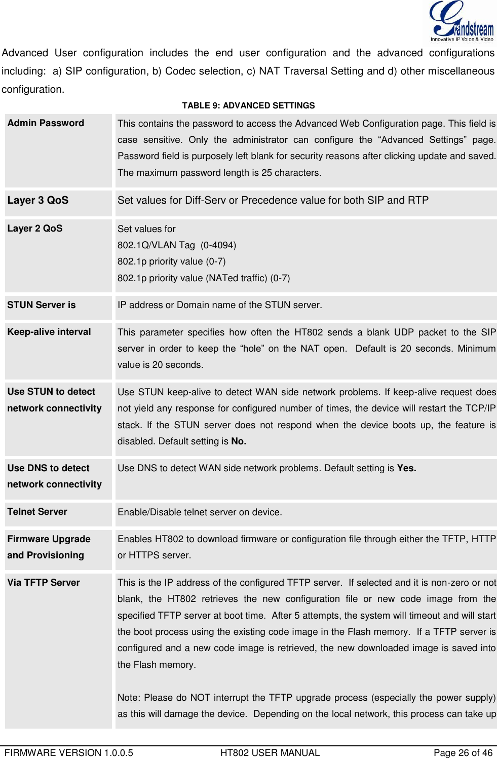
![FIRMWARE VERSION 1.0.0.5 HT802 USER MANUAL Page 34 of 46 phone connected to the FXS port. Ring Timeout Default value is 60 Sec. Incoming call will stop ringing when not picked up given a specific period of time. Delayed Call Forward Wait Time Default value is 20 seconds. In case this feature activated using * codes (*92 code), the call will be forwarded after this preconfigured amount of time. No Key Entry Timeout Default is 4 seconds. Dialing process is completed and outgoing call is initiated if no key entry occurs during this preconfigured interval. Early Dial Default is No. Use only if proxy supports 484 response. This parameter controls whether the phone will send an early INVITE each time a key is pressed when a user dials a number. If set to “Yes”, an INVITE is sent using the dial-number collected thus far; Otherwise, no INVITE is sent until the “(Re-)Dial” button is pressed or after about 5 seconds have elapsed if the user forgets to press the “Re-Dial” button. The “Yes” option should be used ONLY if there is a SIP proxy configured and the proxy server supports 484 Incomplete Address response. Otherwise, the call will likely be rejected by the proxy (with a 404 Not Found error). This feature does NOT work with and should NOT be enabled for direct IP-to-IP calling. Dial Plan Prefix Sets the prefix added to each dialed number. Use # as Dial Key Default is Yes. It allows users to configure the “#” key as the “Send” (or “Dial”) key. If set to “Yes”, “#” will send the number. In this case, this key is essentially equivalent to the “Dial” key. If set to “No”, this “#” key can be included as part of number. Dial Plan Dial Plan Rules: 1. Accept Digits: 1,2,3,4,5,6,7,8,9,0 , *, #, A,a,B,b,C,c,D,d 2. Grammar: x - any digit from 0-9; xx+ - at least 2 digits number; xx. – at least 2 digit number. ^ - exclude; [3-5] - any digit of 3, 4, or 5; [147] - any digit 1, 4, or 7; <2=011> - replace digit 2 with 011 when dialing < =1> - add a leading 1 to all numbers dialed, vice versa will remove a 1 from the number dialed | - or • Example 1: {[369]11 | 1617xxxxxxx} – Allow 311, 611, 911, and any 11 digit numbers with leading digits 1617 Example 2: {^1900x+ | <=1617>xxxxxxx} – Block any number of leading digits](https://usermanual.wiki/Grandstream-Networks/HT802/User-Guide-2486780-Page-36.png)
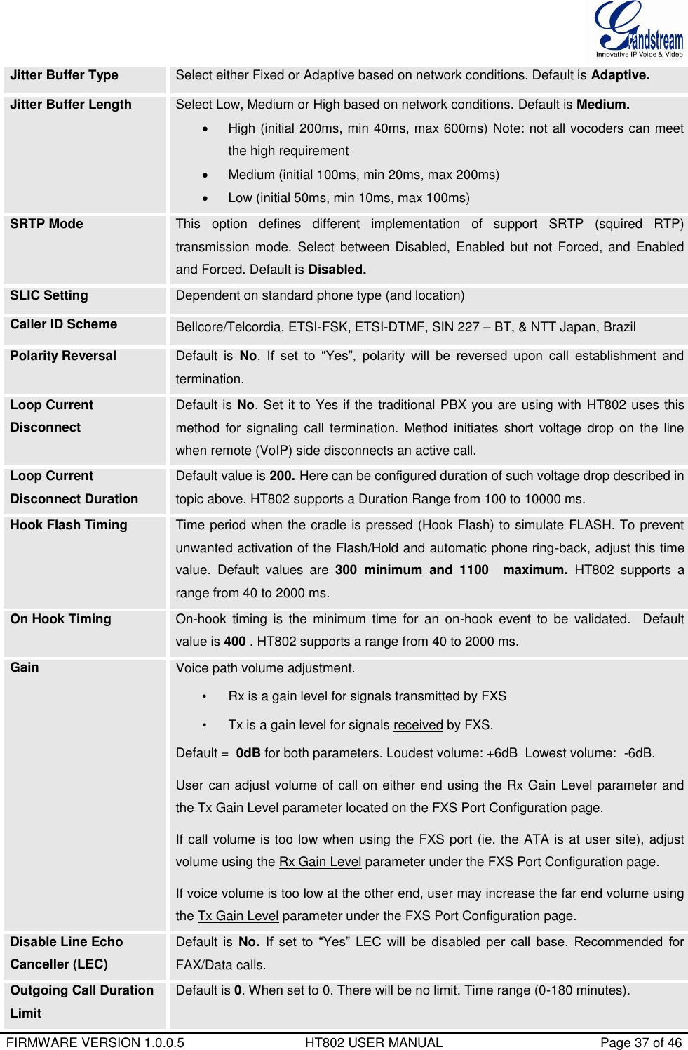
![FIRMWARE VERSION 1.0.0.5 HT802 USER MANUAL Page 35 of 46 1900 and add prefix 1617 for any dialed 7 digit numbers • Example 3: {1xxx[2-9]xxxxxx | <2=011>x+} –Allow any combinations of numbers with 11 digits which has a leading digit 1, but 5th digit cannot be 0 or 1. Or any length of numbers with a minimum of 2 digits beginning with 2, with the leading digit replaced with 011. 3. Default: Outgoing - {x+} Example of a simple dial plan used in a Home/Office in the US: { ^1900x. | <=1617>[2-9]xxxxxx | 1[2-9]xx[2-9]xxxxxx | 011[2-9]x. | [3469]11 } Explanation of example rule (reading from left to right): • ^1900x. - prevents dialing any number started with 1900 • <=1617>[2-9]xxxxxx - allows dialing to local area code (617) numbers by dialing 7 numbers and 1617 area code will be added automatically • 1[2-9]xx[2-9]xxxxxx |- allows dialing to any US/Canada Number with 11 digits length • 011[2-9]x. - allows international calls starting with 011 • [3469]11 - allow dialing special and emergency numbers 311, 411, 611 and 911 Note: In some cases user wishes to dial strings such as *123 to activate voice mail or other application provided by service provider. In this case * should be predefined inside dial plan feature and the Dial Plan should be: { *x+ }. Subscribe for MWI Default is No. When set to “Yes” a SUBSCRIBE for Message Waiting Indication will be sent periodically. Send Anonymous Default is No. If this parameter is set to “Yes”, the “From” header along with Privacy and P_ Asserted_Identity headers in outgoing INVITE message will be set to anonymous, blocking Caller ID. Anonymous Call Rejection Default is No. If set to Yes, incoming calls with anonymous Caller ID will be rejected with 486 Busy message. Special Feature Default is Standard. Choose the selection to meet some special requirements from Softswitch vendors. Session Expiration Grandstream implemented SIP Session Timer. The session timer extension enables SIP sessions to be periodically “refreshed” via a SIP request (UPDATE, or re-INVITE. Once the session interval expires, if there is no refresh via a UPDATE or re-INVITE message, the session will be terminated. Session Expiration is the time (in seconds) at which the session is considered timed out, if no successful session refresh transaction occurs beforehand. The default value is 180 seconds. Min-SE The minimum session expiration (in seconds). The default value is 90 seconds. Caller Request Timer Default is No. If selecting “Yes” the phone will use session timer when it makes outbound calls if remote party supports session timer.](https://usermanual.wiki/Grandstream-Networks/HT802/User-Guide-2486780-Page-37.png)