Grandstream Networks HT813 Analog Telephone Adaptors User Manual
Grandstream Networks, Inc. Analog Telephone Adaptors
UserManual.wiki
>
Grandstream Networks
>
HT813 User Manual
User Manual
Navigation menu
Upload a User Manual
Namespaces
Wiki Guide
HTML
PDF
Info
Views
User Manual
Discussion / Help
Navigation

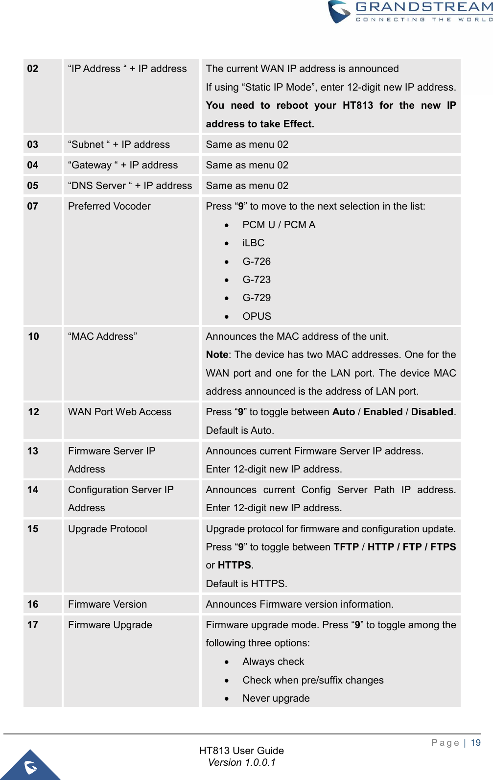
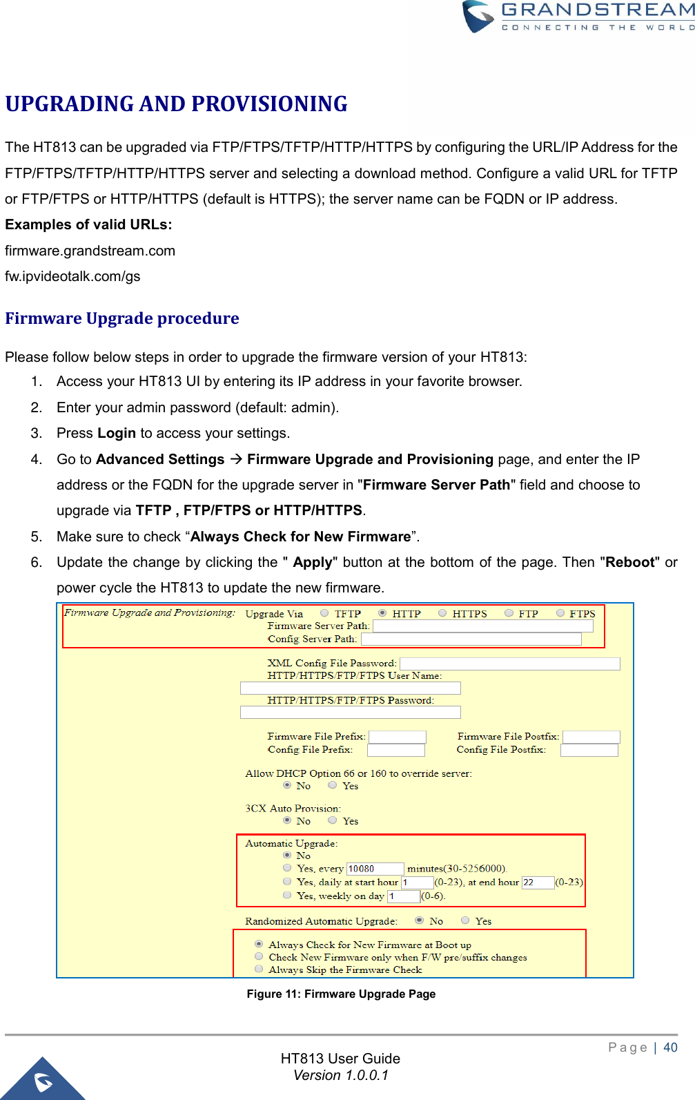
![P a g e | 23 HT813 User Guide Version 1.0.0.1 2. Enter your admin password (default: admin). 3. Press Login to access your settings. 4. Go to Basic Settings → New Viewer Password and enter the new viewer password. 5. Confirm the new viewer password. 6. Press Apply at the bottom of the page to save your new settings. Figure 7: Viewer Level Password Changing HTTP/HTTPS Web Port 1. Access your HT813 web UI by entering its IP address in your favorite browser. 2. Enter your admin password (default: admin). 3. Press Login to access your settings. 4. Go to Basic Settings → HTTP(S) Web Port. 5. Make sure that the Web Access Mode is set to HTTP(S). 6. Change the current port to your new HTTP(S) port. Ports accepted are in range [1-65535]. 7. Press Apply at the bottom of the page to save your new settings Figure 8: Web HTTP(S) Port](https://usermanual.wiki/Grandstream-Networks/HT813/User-Guide-3904781-Page-24.png)