Grandstream Networks HT814 Analog Telephone Adaptor/FXS Gateway User Manual
Grandstream Networks, Inc. Analog Telephone Adaptor/FXS Gateway
UserManual.wiki
>
Grandstream Networks
>
HT814 User Manual
User Manual
Navigation menu
Upload a User Manual
Namespaces
Wiki Guide
HTML
PDF
Info
Views
User Manual
Discussion / Help
Navigation

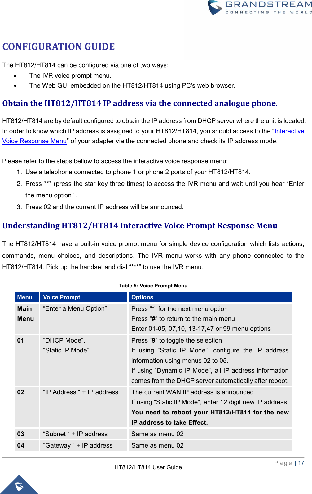
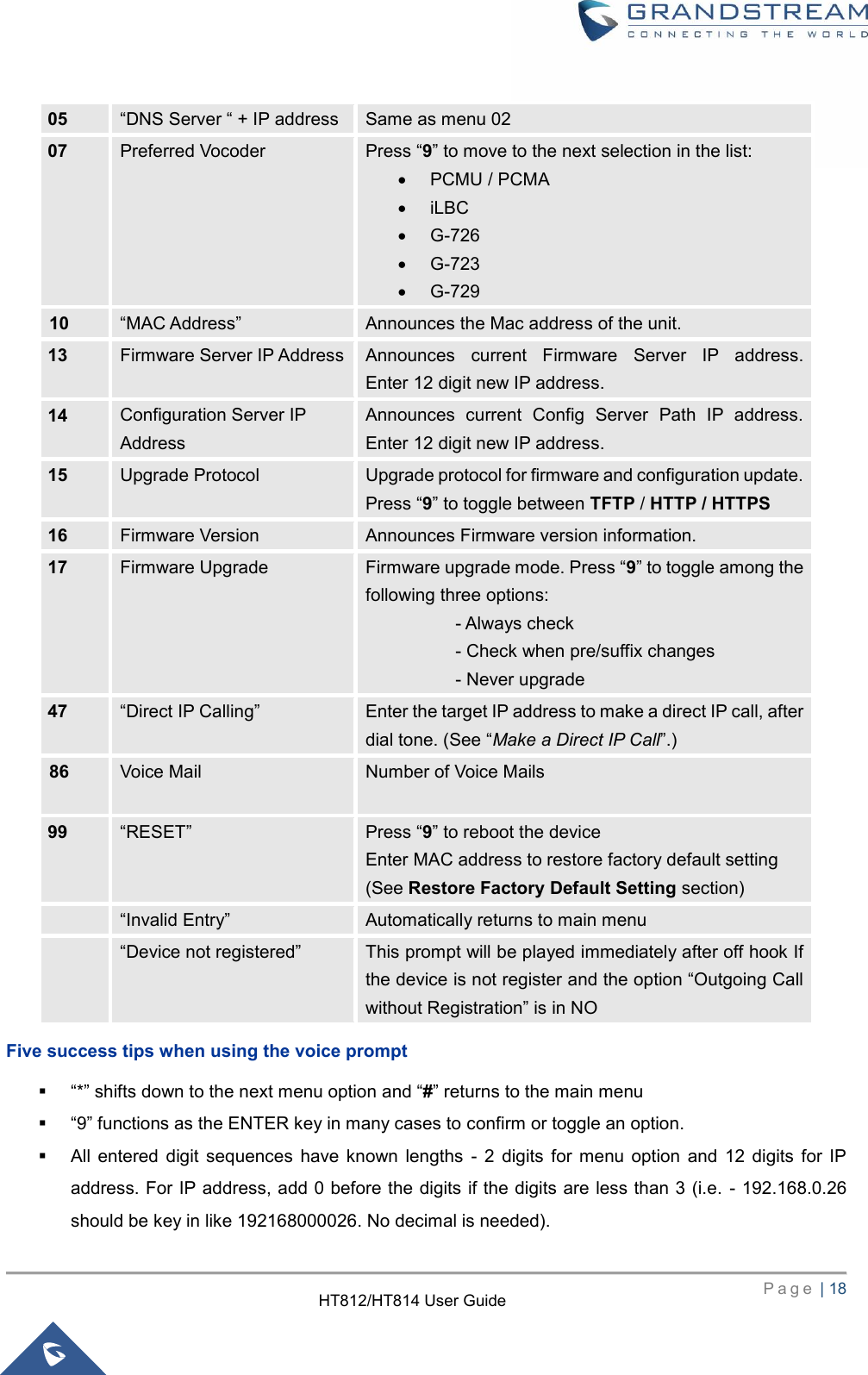
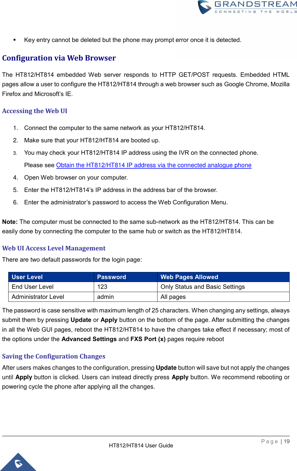
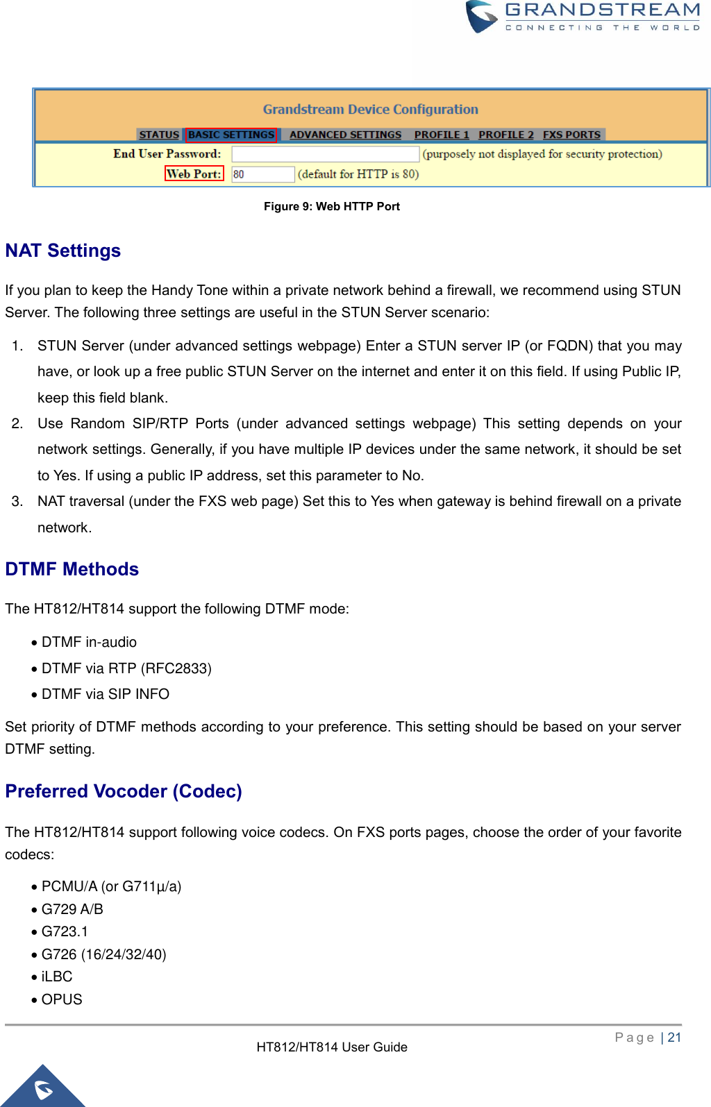
![P a g e | 20 HT812/HT814 User Guide Changing Admin Level Password 1. Access your HT812/HT814 web UI by entering its IP address in your favorite browser. 2. Enter your admin password (default: admin). 3. Press Login to access your settings. 4. Go to Advanced Settings > Admin Password. 5. Enter the new admin password. 6. Press Apply at the bottom of the page to save your new settings. Changing User Level Password 1. Access your HT812/HT814 web UI by entering its IP address in your favorite browser. 2. Enter your admin password (default: admin). 3. Press Login to access your settings. 4. Go to Basic Settings > End User Password. 5. Enter the new end-user password. 6. Press Apply at the bottom of the page to save your new settings. Changing HTTP Web Port 1. Access your HT812/HT814 web UI by entering its IP address in your favorite browser. 2. Enter your admin password (default: admin). 3. Press Login to access your settings. 4. Go to Basic Settings > Web Port. 5. Change the current port to your desired/new HTTP port. Ports accepted are in range [1-65535]. 6. Press Apply at the bottom of the page to save your new settings Figure 7: Admin Level Password Figure 8: User Level Password](https://usermanual.wiki/Grandstream-Networks/HT814/User-Guide-3042575-Page-21.png)