Grandstream Networks UCM6202 IP PBX User Manual
Grandstream Networks, Inc. IP PBX
UserManual.wiki
>
Grandstream Networks
>
UCM6202 User Manual
User Manual
Navigation menu
Upload a User Manual
Namespaces
Wiki Guide
HTML
PDF
Info
Views
User Manual
Discussion / Help
Navigation


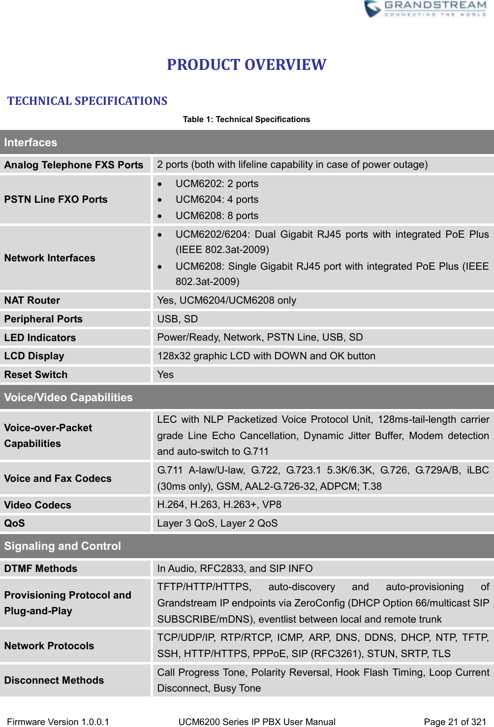

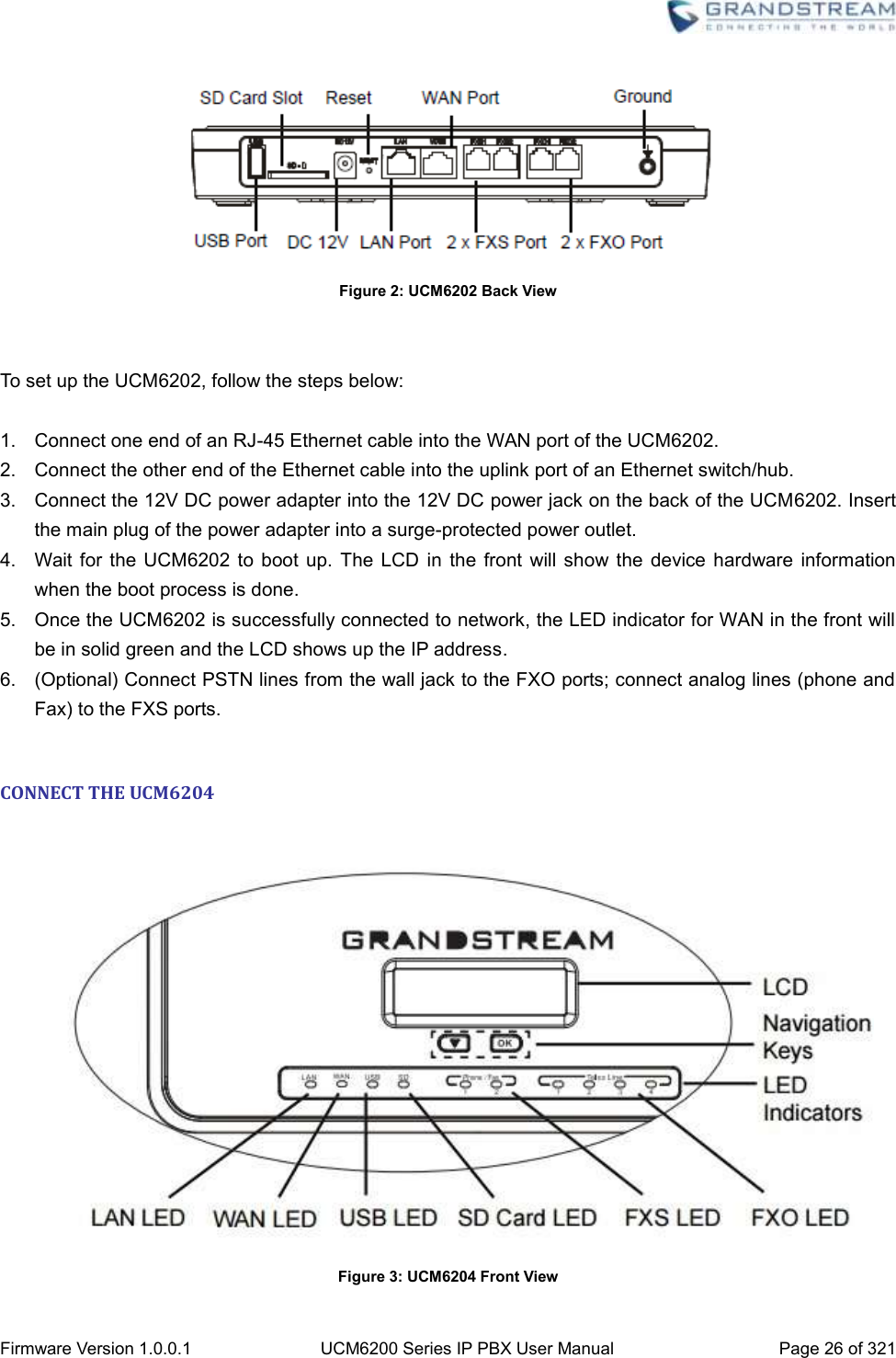
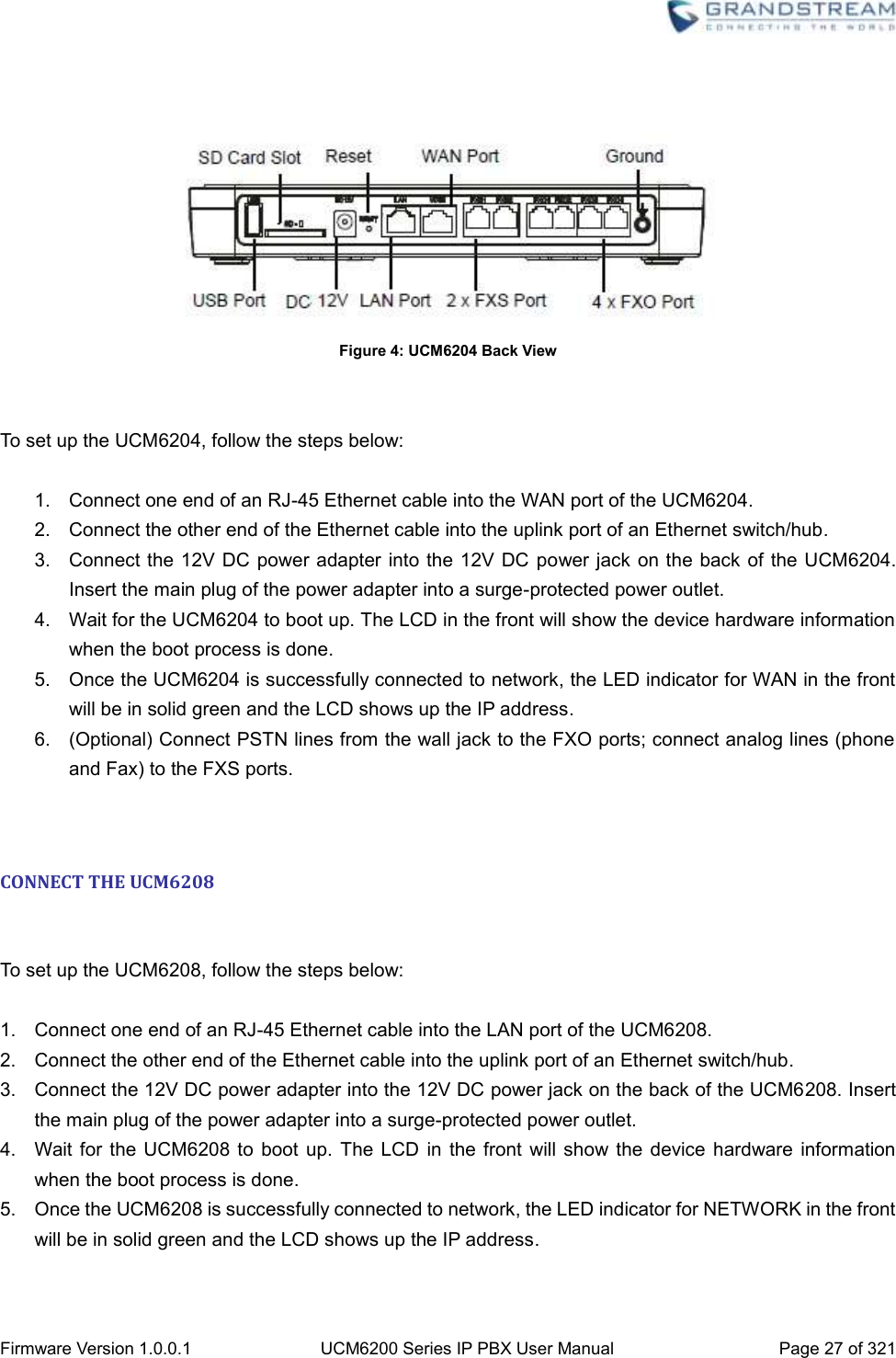


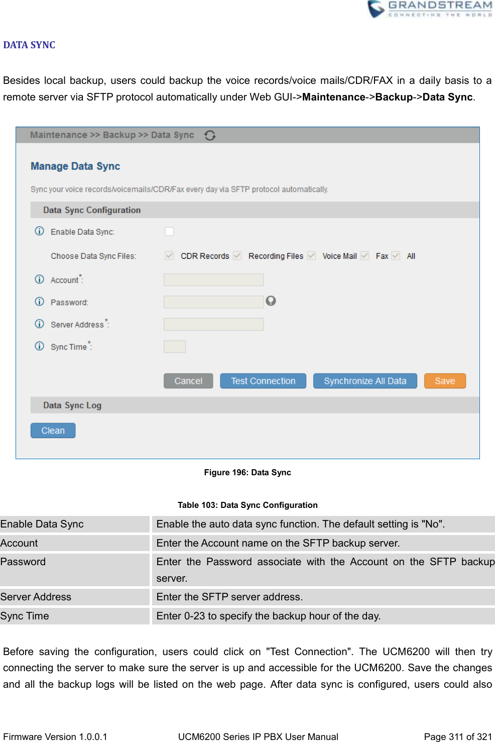
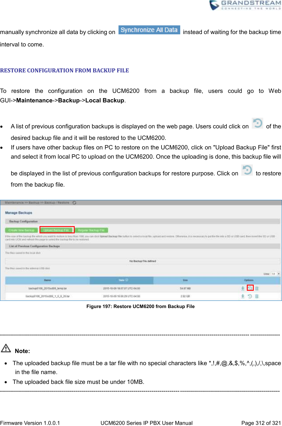
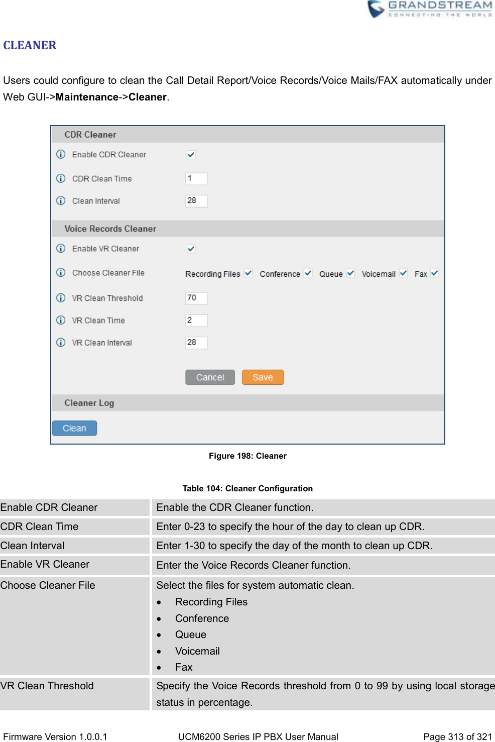
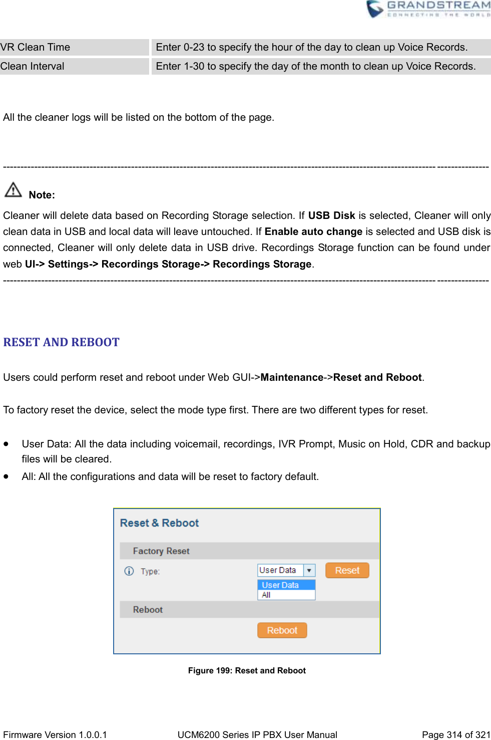
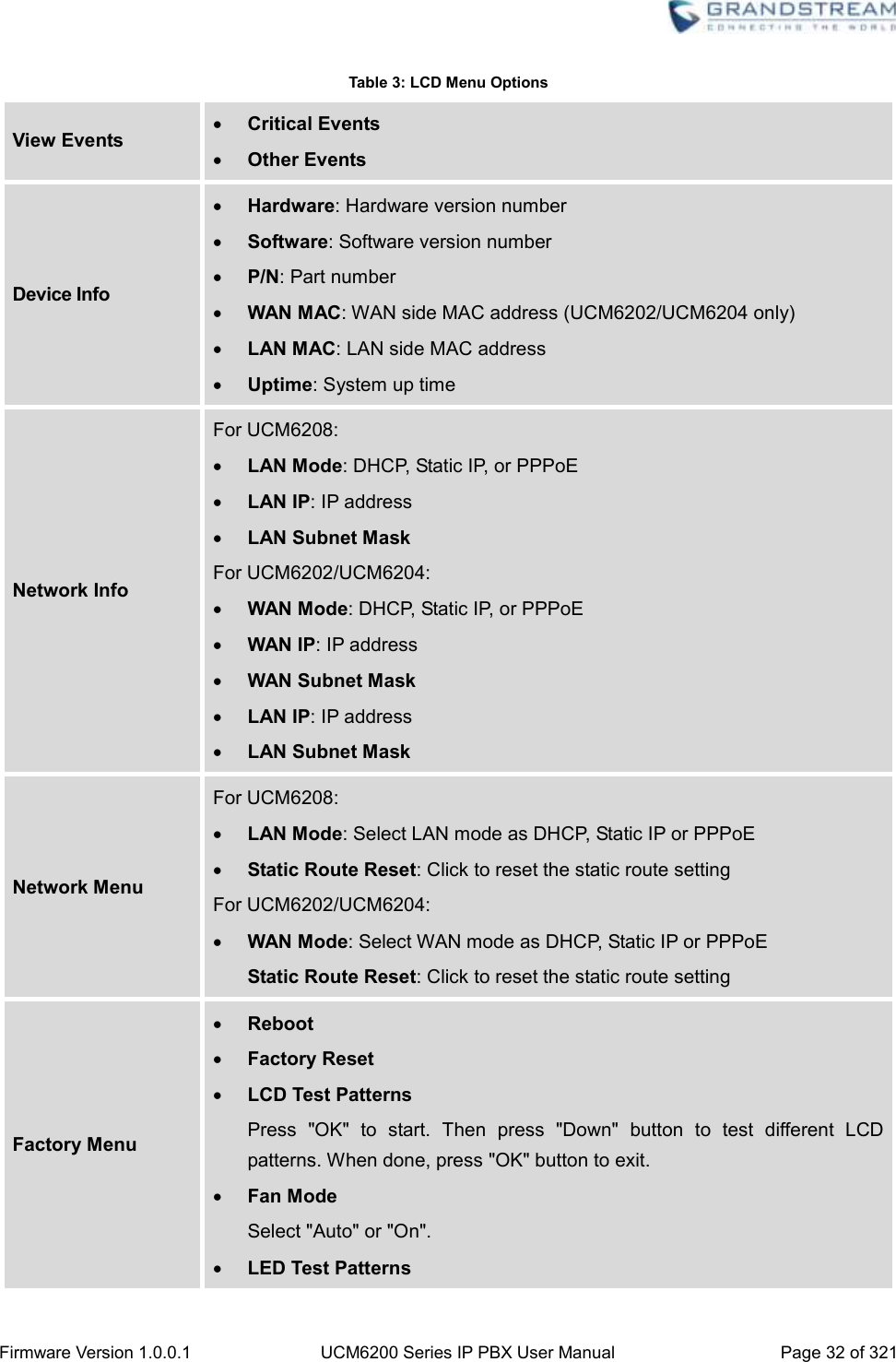
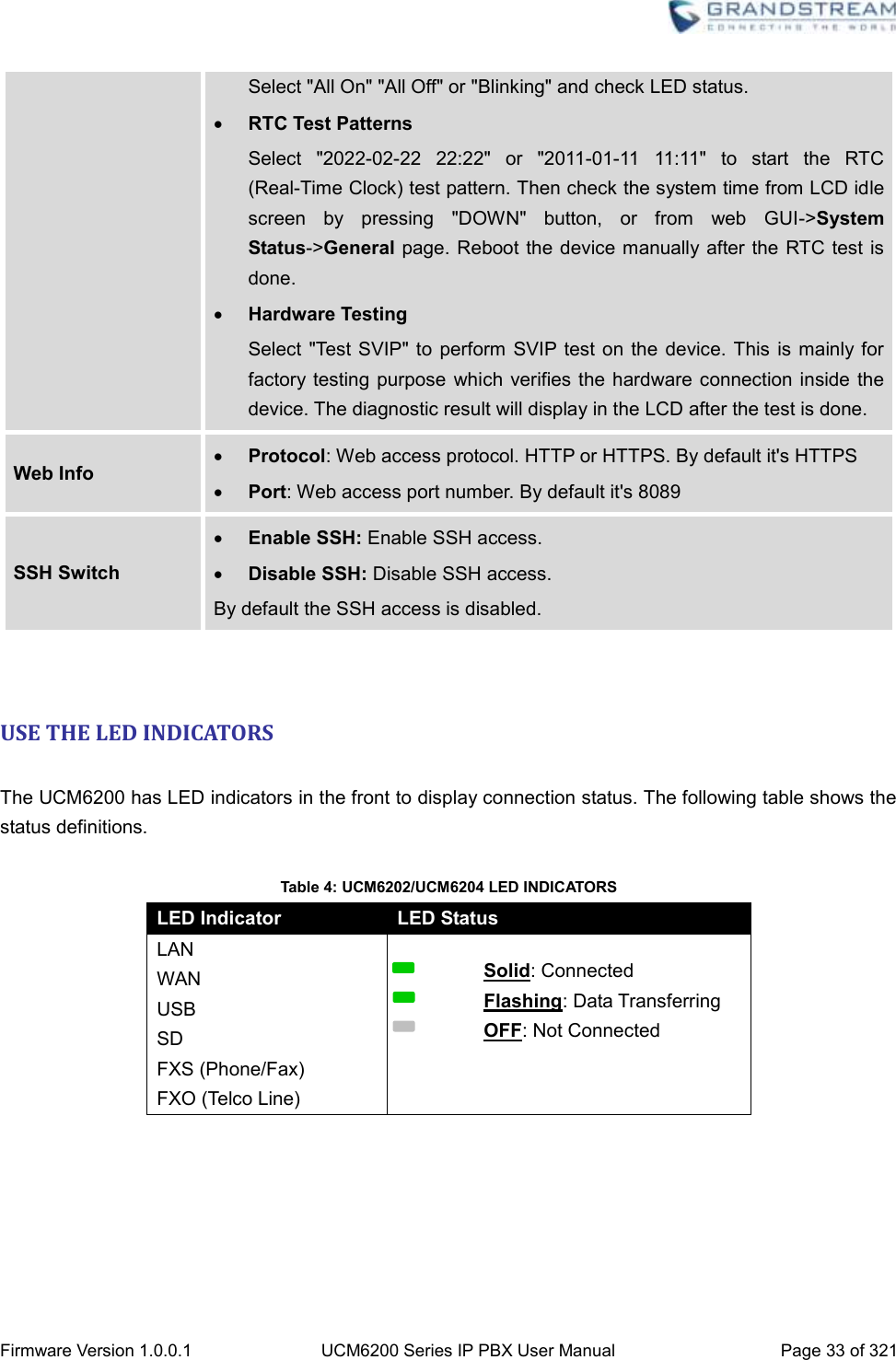
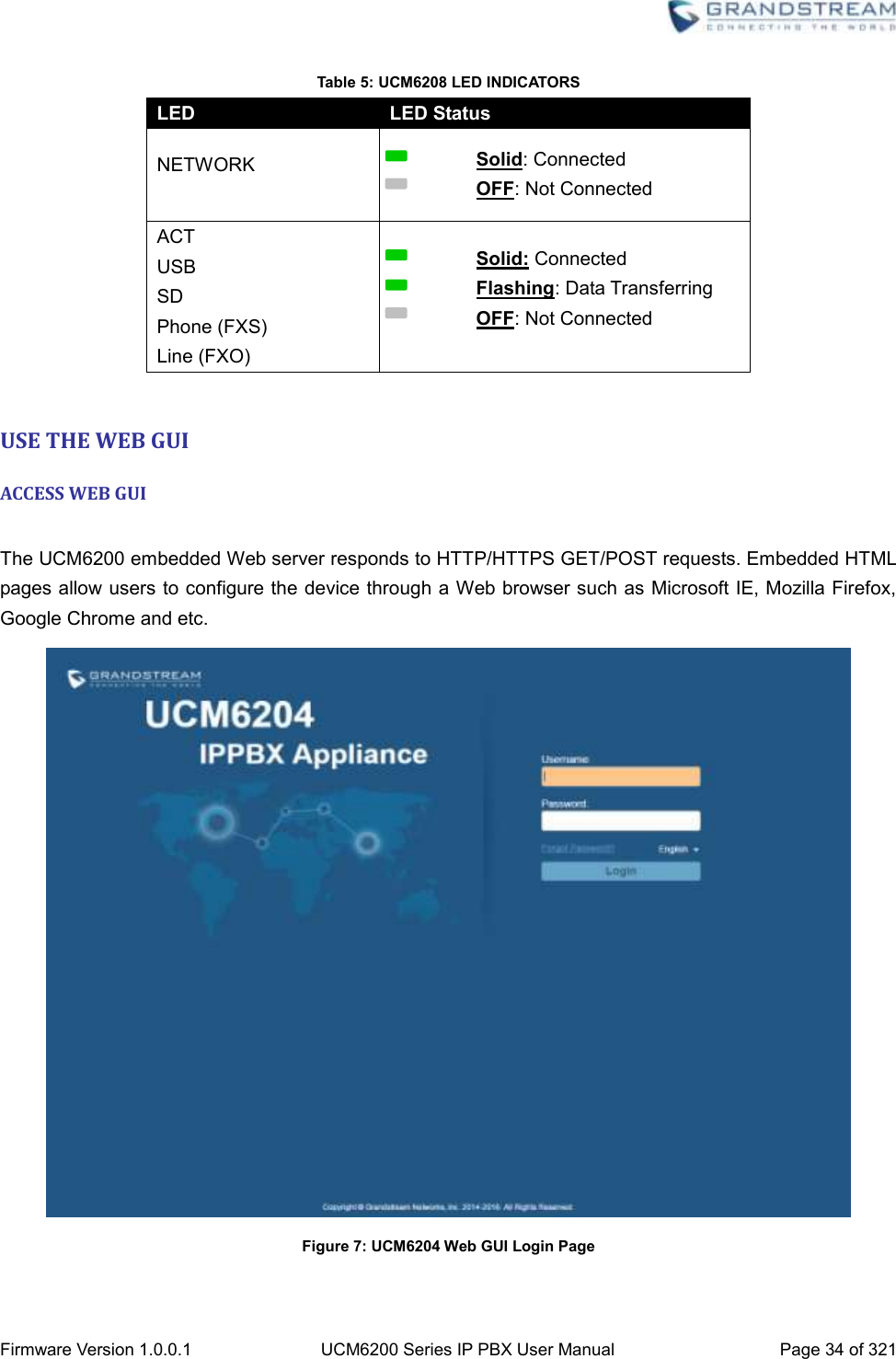
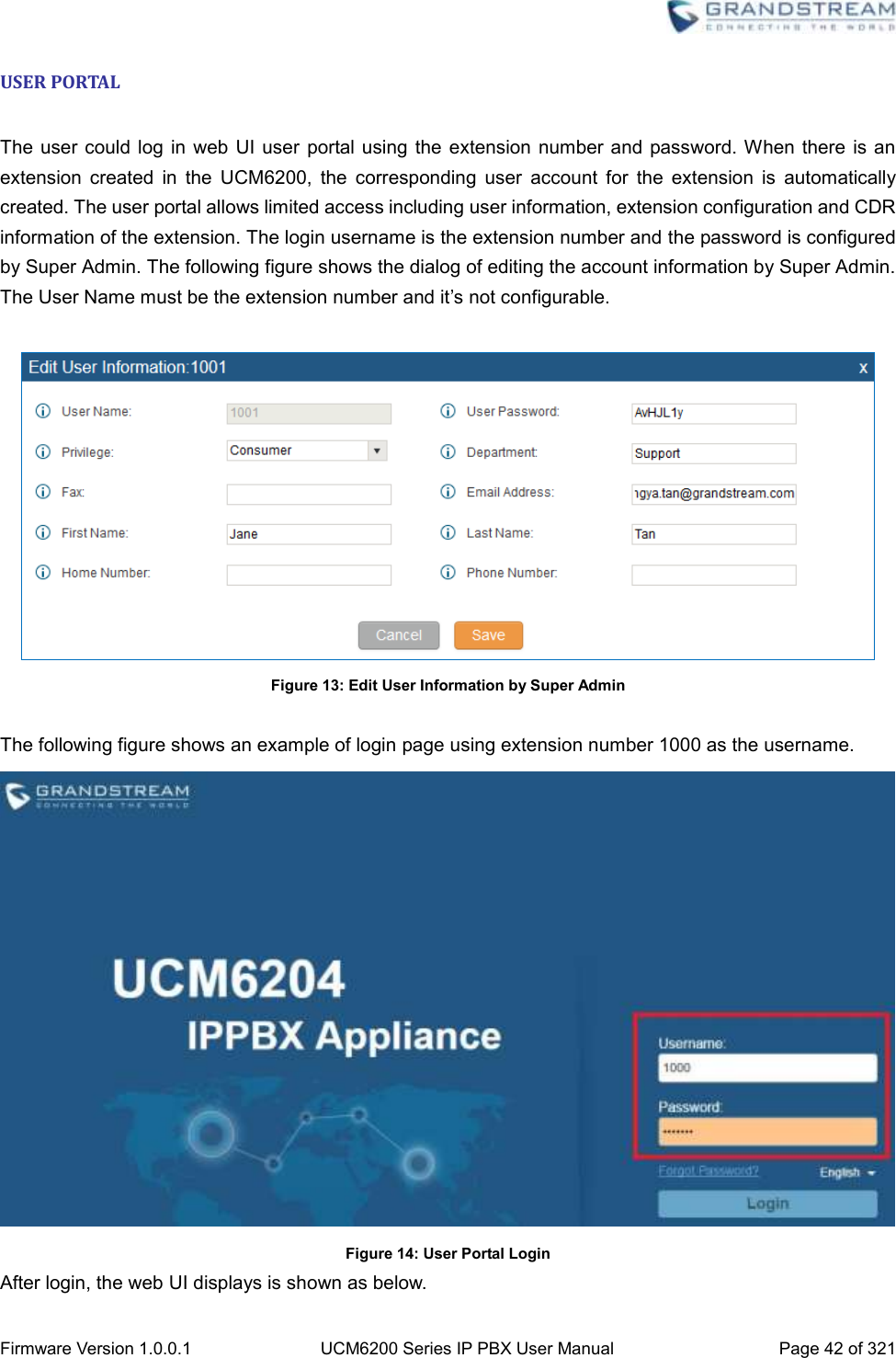
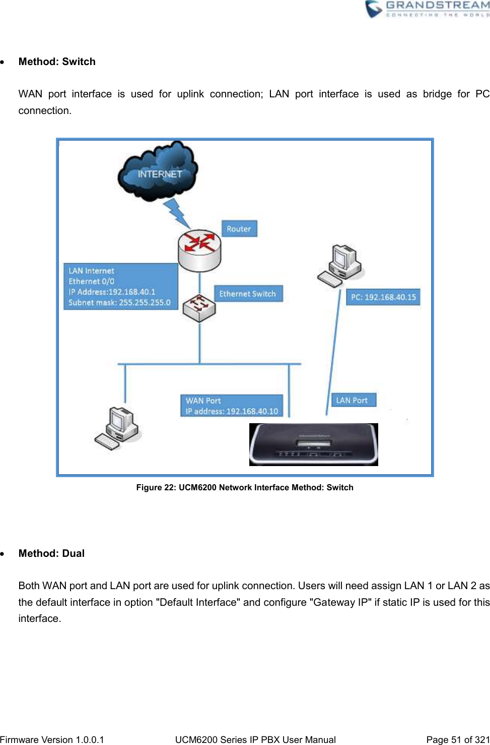
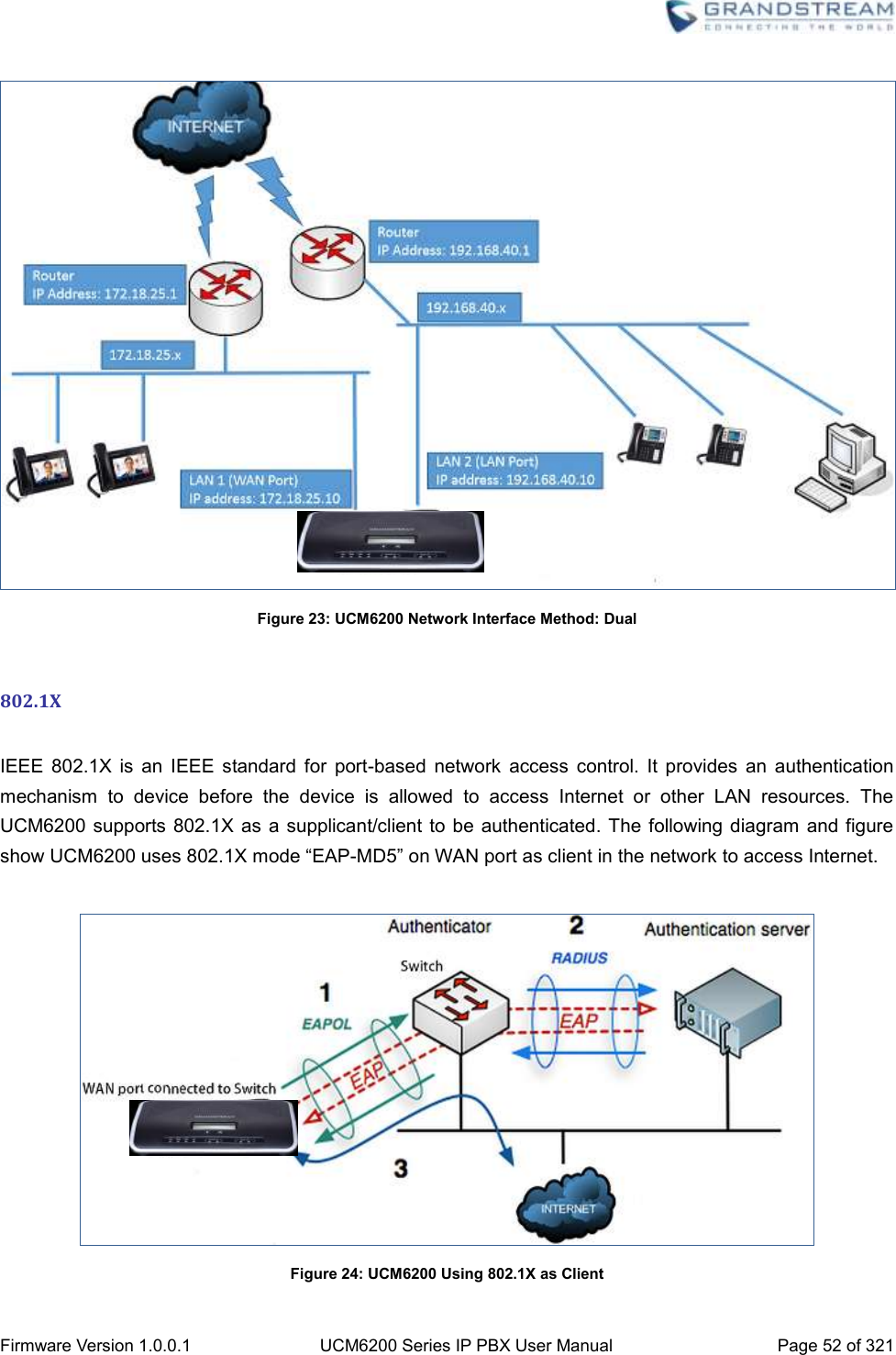
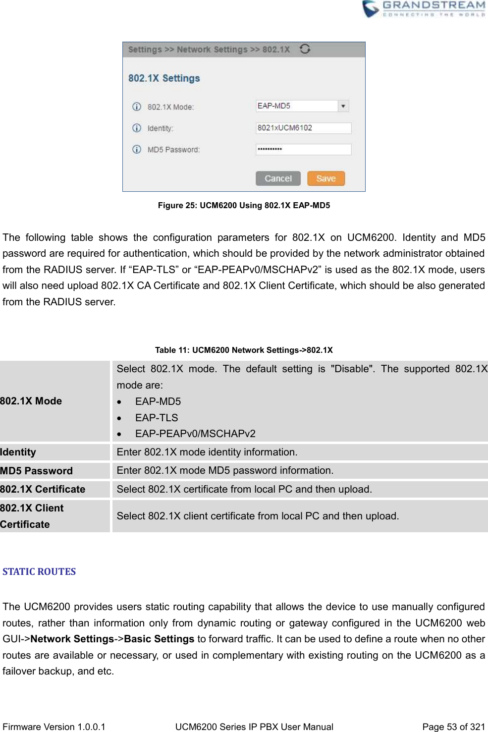
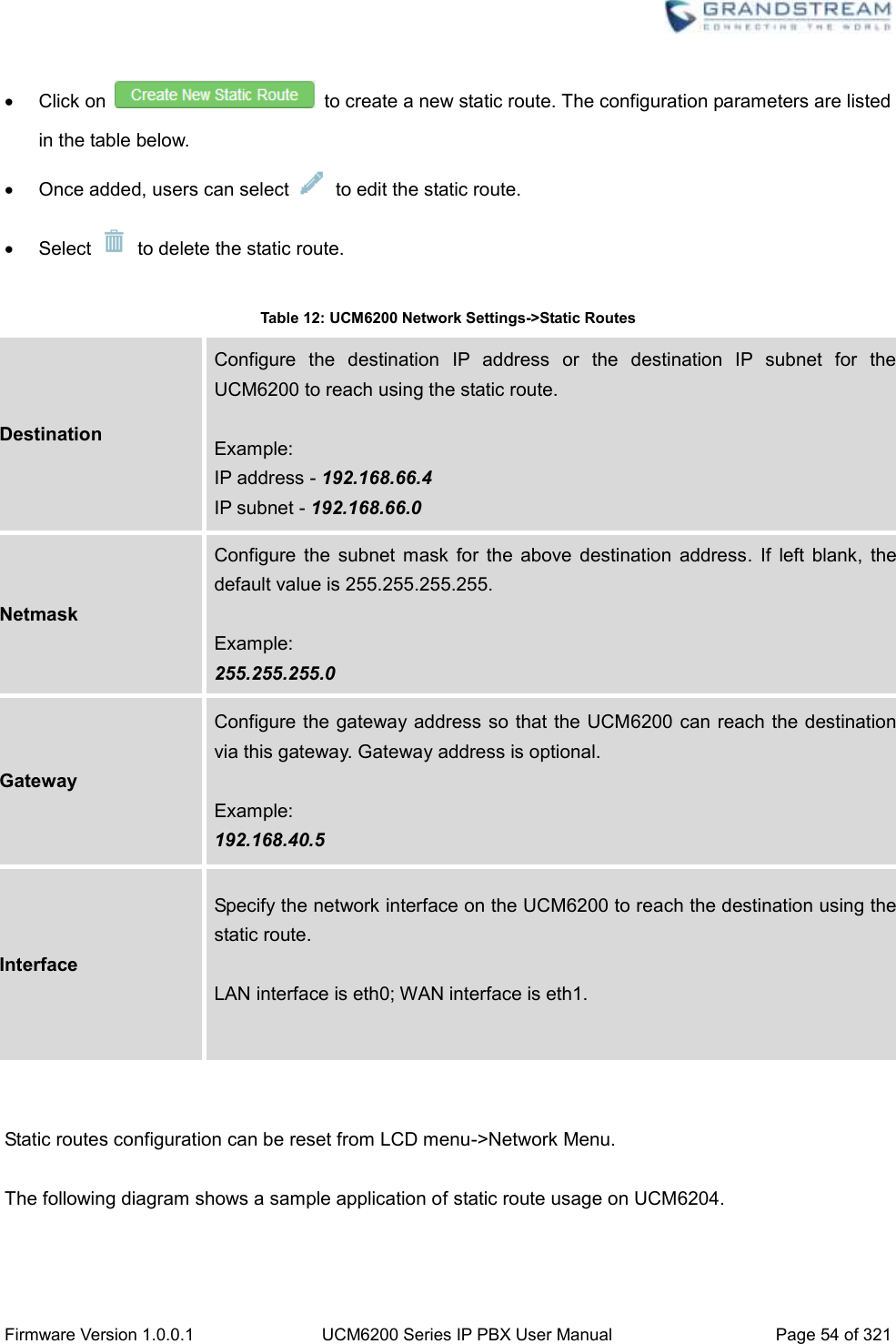
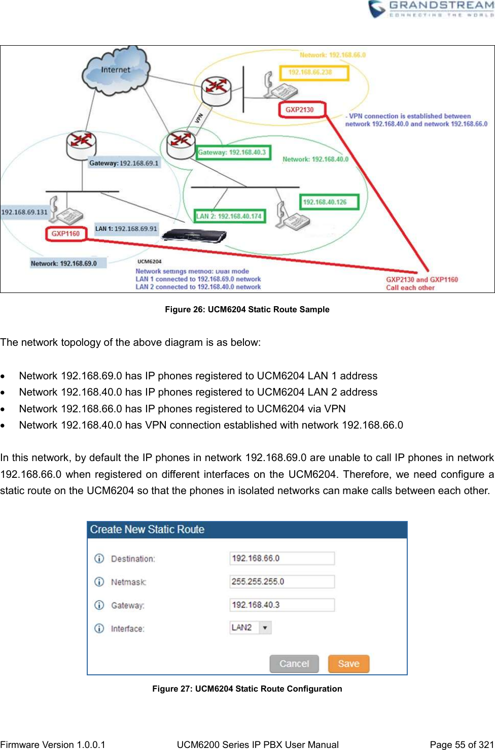
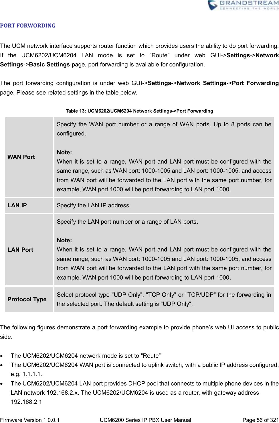
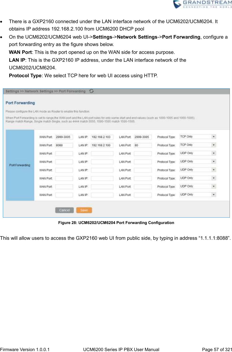
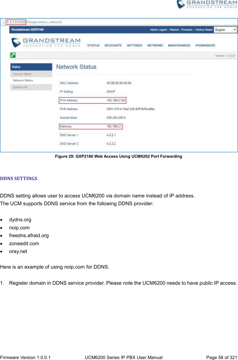
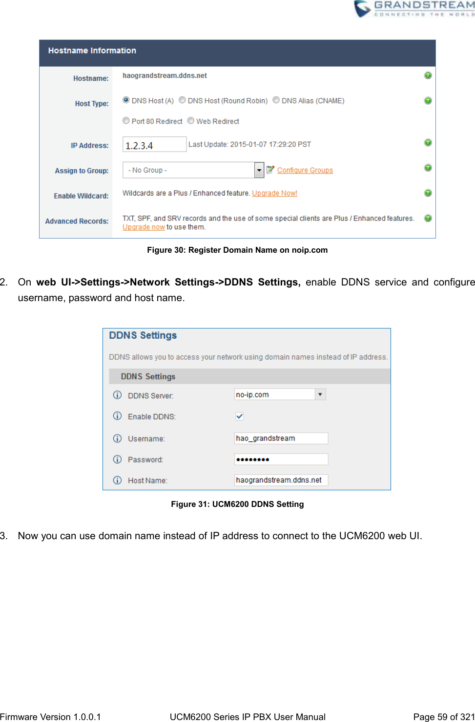
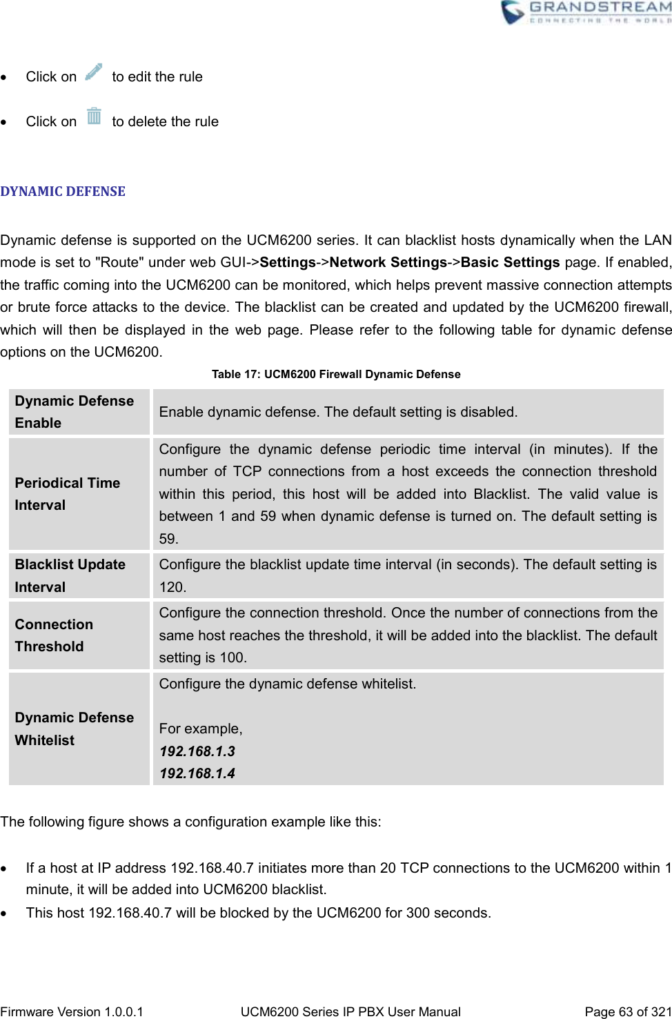
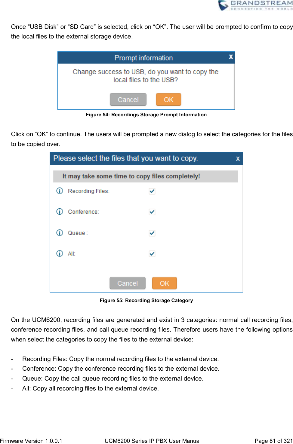
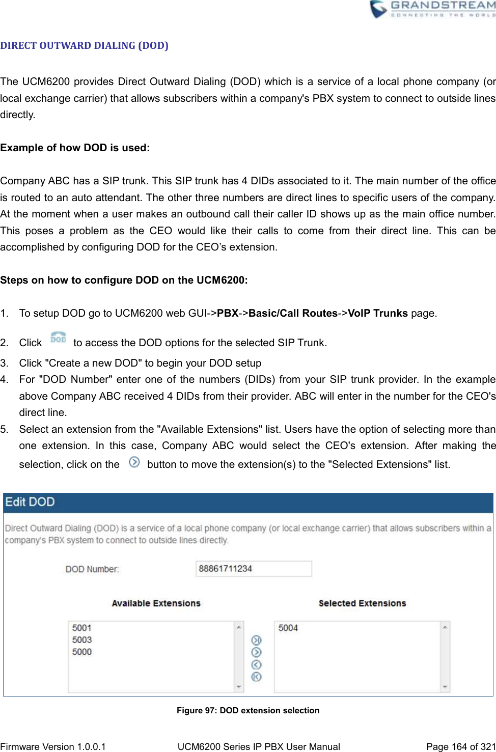
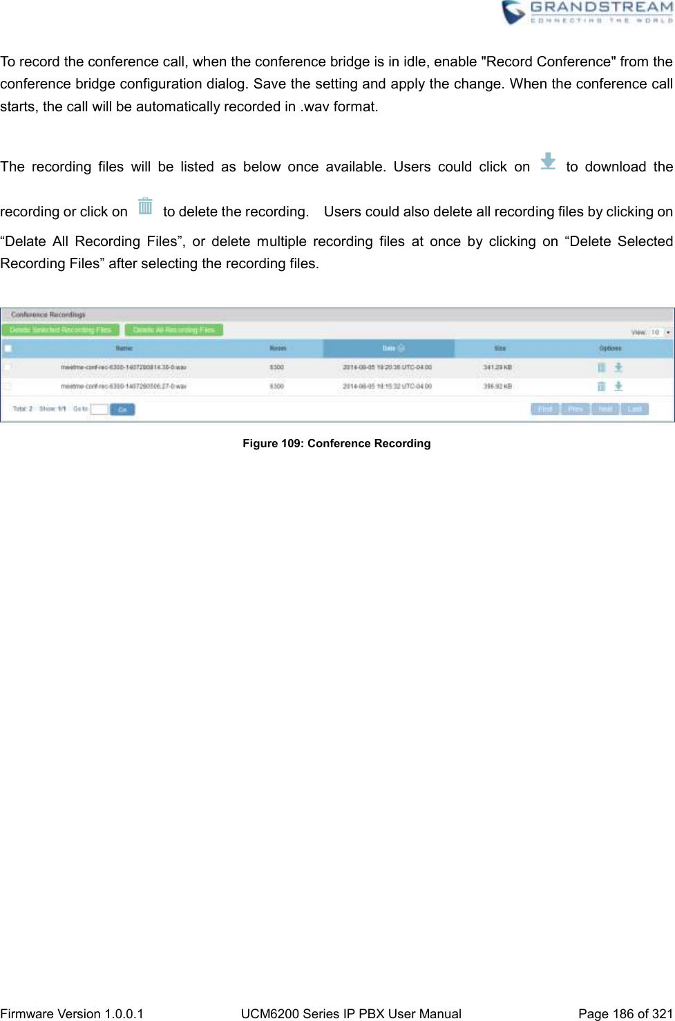
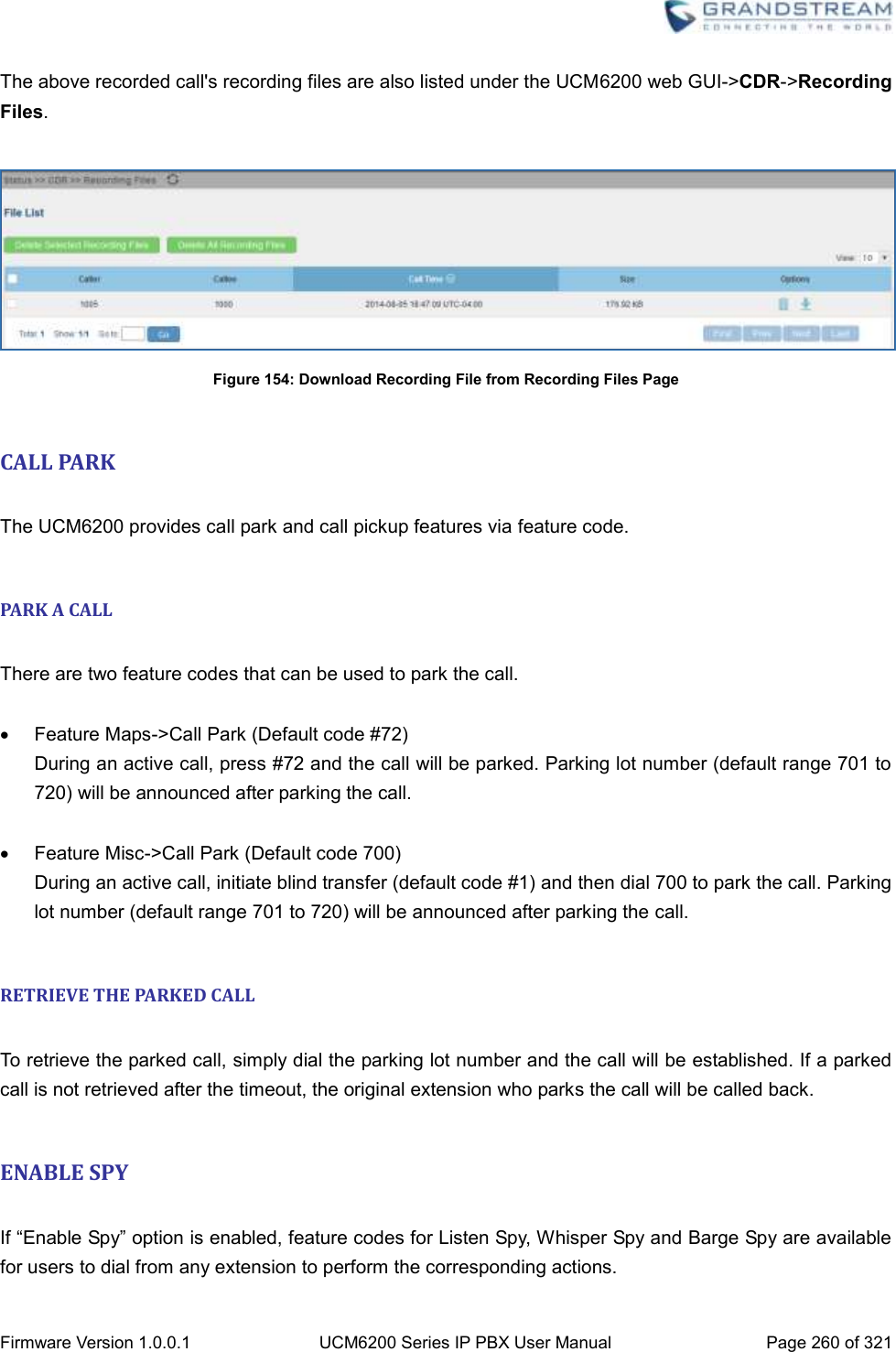
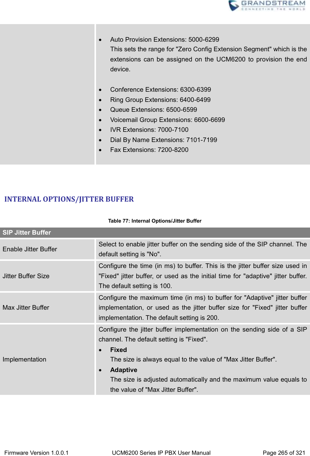
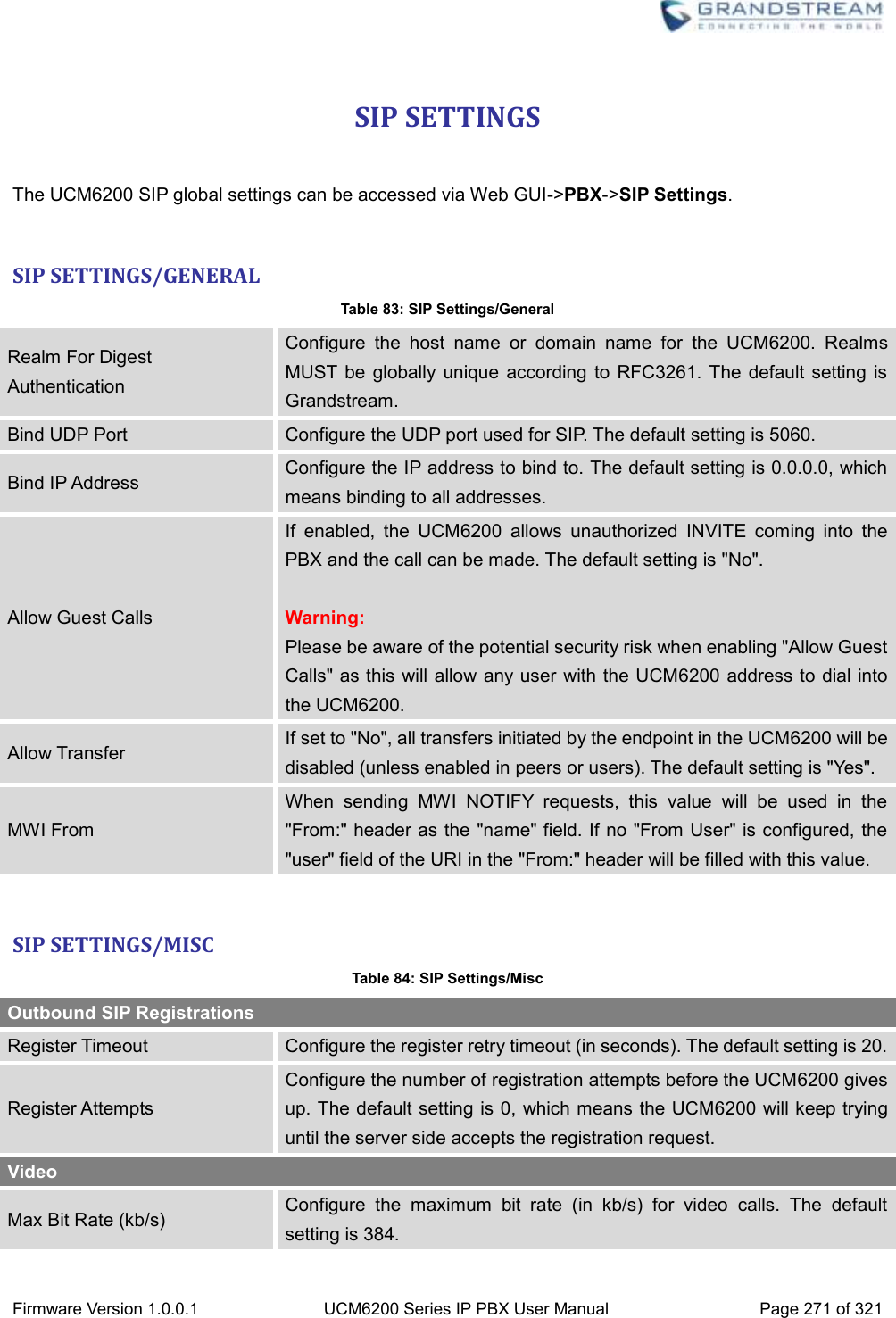
![Firmware Version 1.0.0.1 UCM6200 Series IP PBX User Manual Page 31 of 321 GETTING STARTED The UCM6200 series provides LCD interface, LED indication and web GUI configuration interface. The LCD displays hardware, software and network information. Users could also navigate in the LCD menu for device information and basic network configuration. The LED indication at the front of the device provides interface connection and activity status. The web GUI gives users access to all the configurations and options for UCM6200 series setup. This section provides step-by-step instructions on how to use the LCD menu, LED indicators and Web GUI of the UCM6200 series. Once the basic settings are done, users could start making calls from UCM6200 extension registered on a SIP phone as described at the end of this section. USE THE LCD MENU Default LCD Display When the device is powered up, the LCD will show device model (e.g., UCM6204), hardware version (e.g., V1.0A) and IP address. Press "Down" button and the system time will be displayed as well. Menu Access Press "OK" button to start browsing menu options. Please see menu options in [Table 3: LCD Menu Options]. Menu Navigation Press the "Down" arrow key to browser different menu options. Press the "OK" button to select an entry. Exit If "Back" option is available in the menu, select it to go back to the previous menu. For "Device Info" "Network Info" and "Web Info" which do not have "Back" option, simply press the "OK" button to go back to the previous menu. Also, the LCD will display default idle screen after staying in menu option for 15 seconds. LCD Backlight The LCD backlight will be on upon key pressing. The backlight will go off after the LCD stays in idle for 30 seconds.](https://usermanual.wiki/Grandstream-Networks/UCM6202/User-Guide-3010507-Page-32.png)
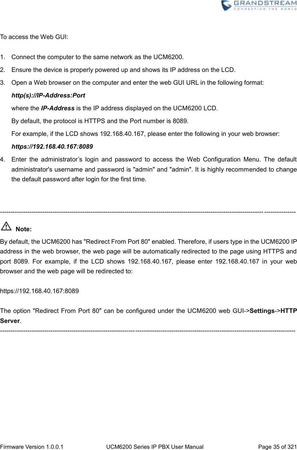
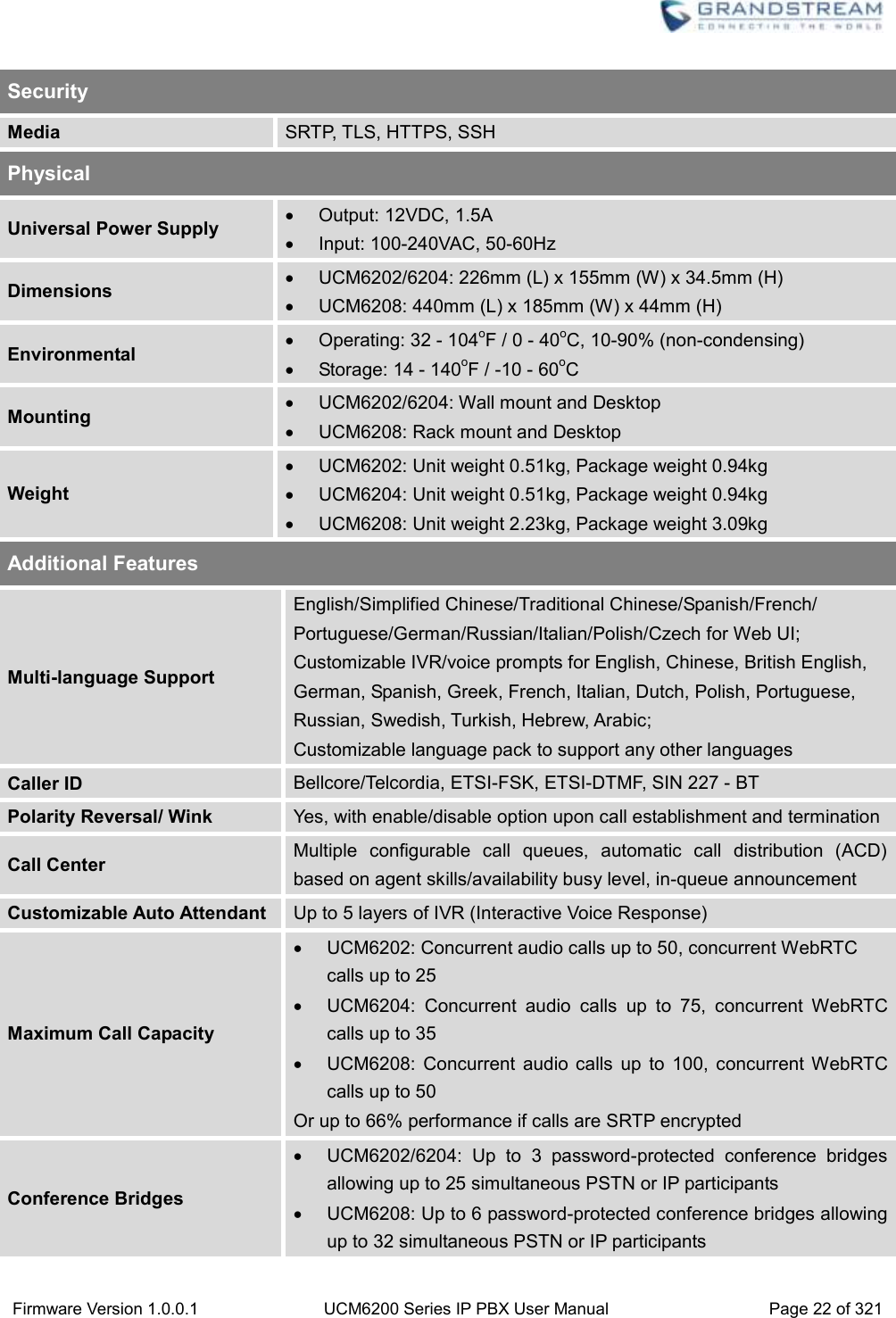
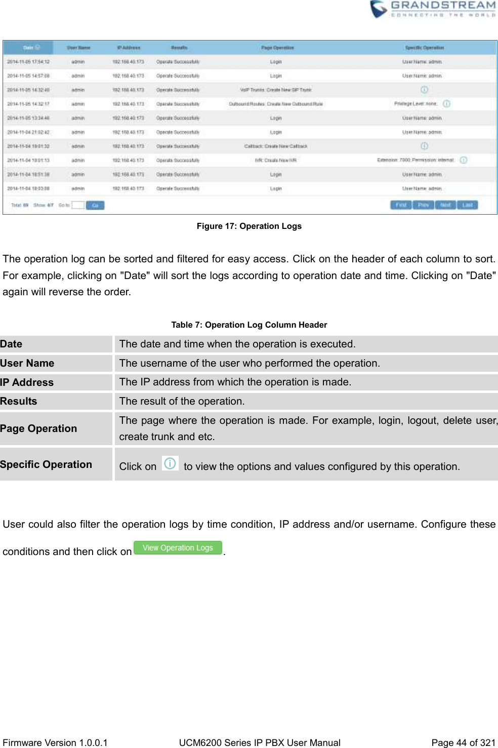
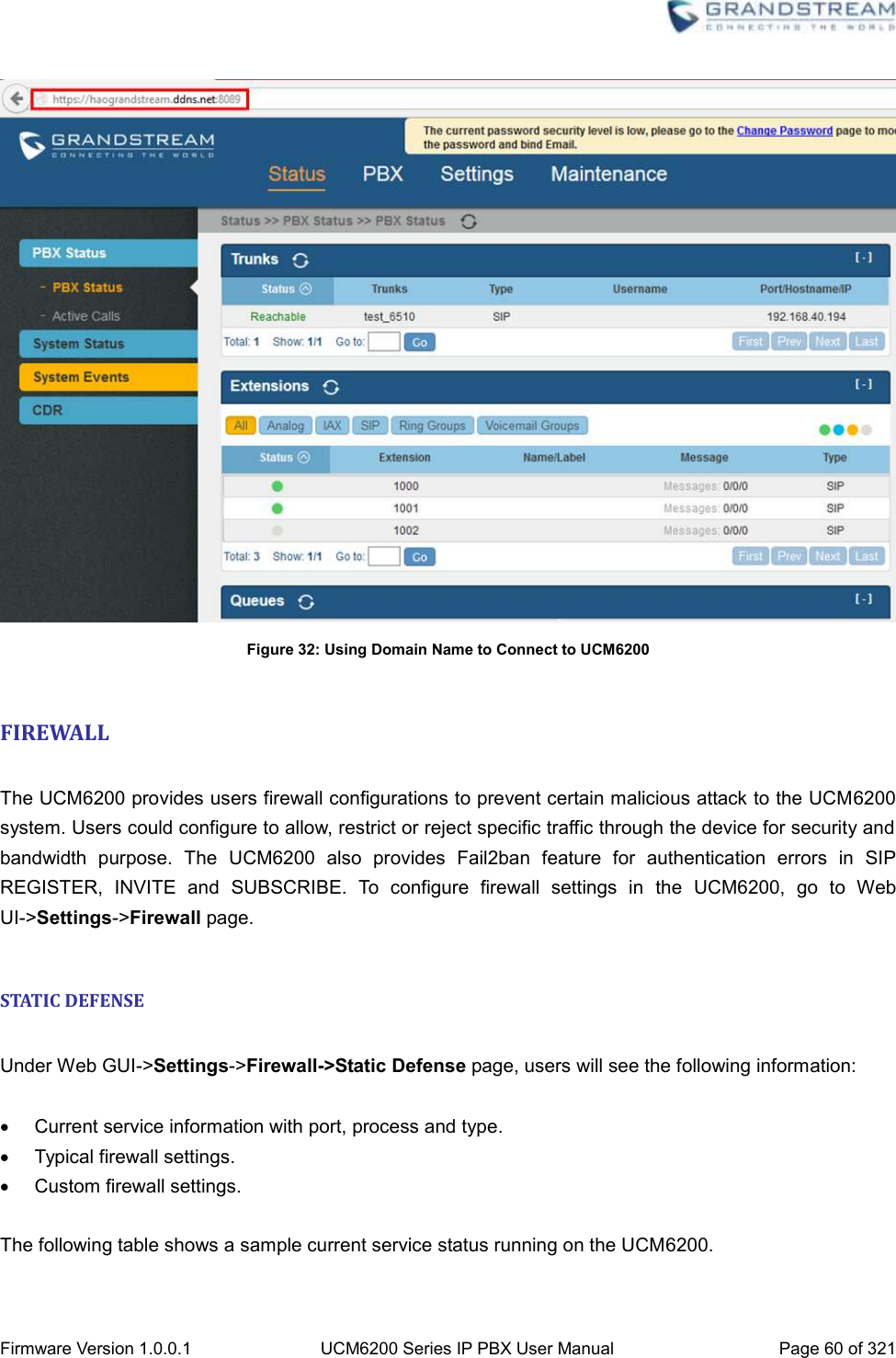
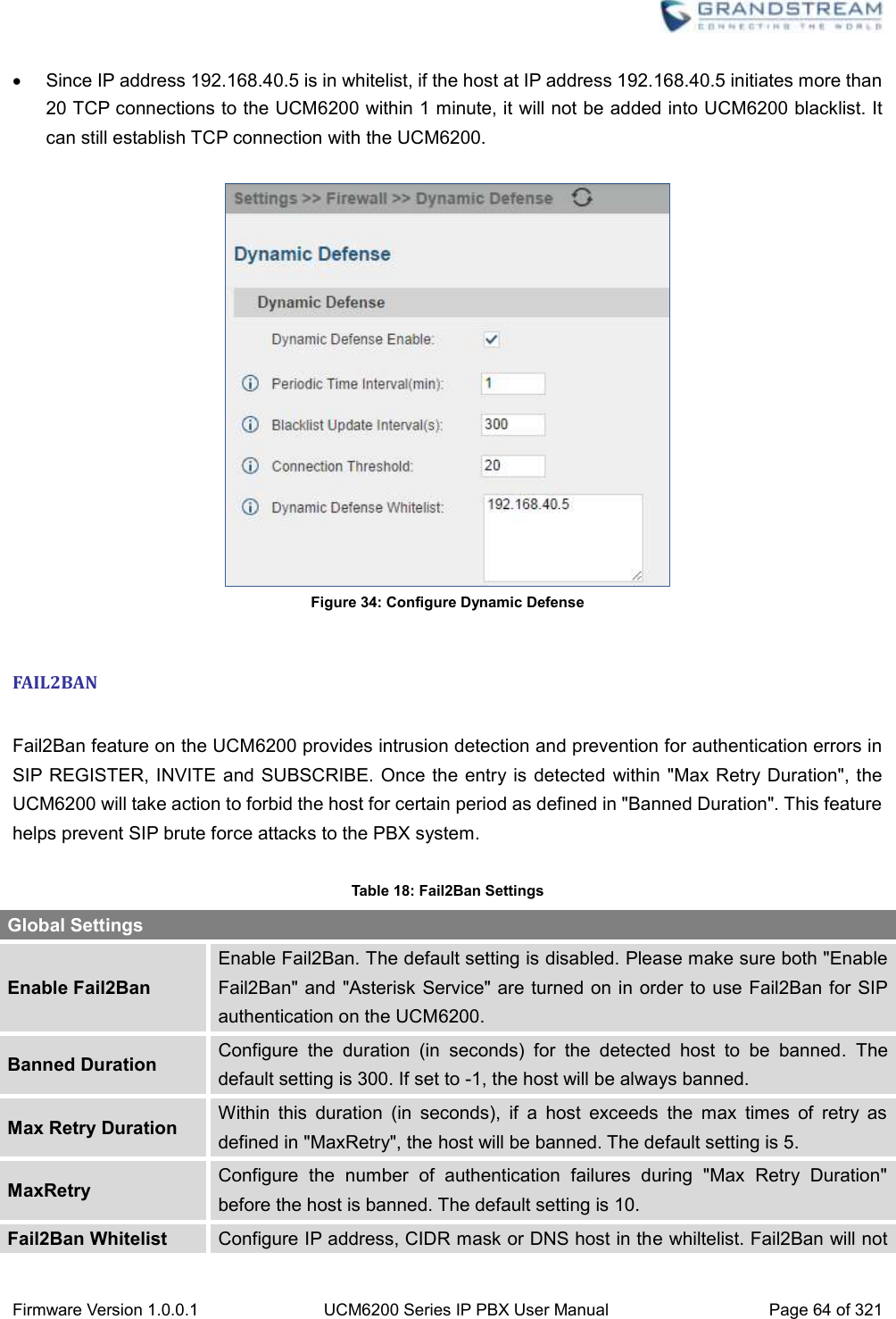
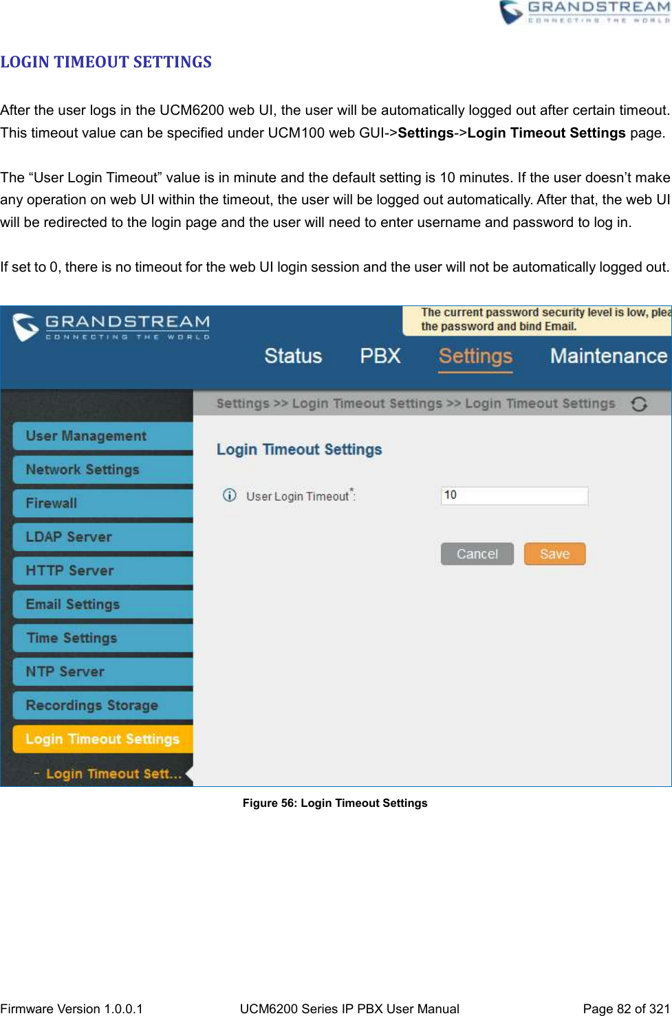
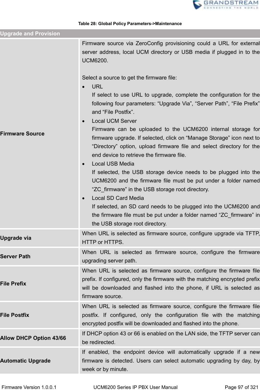
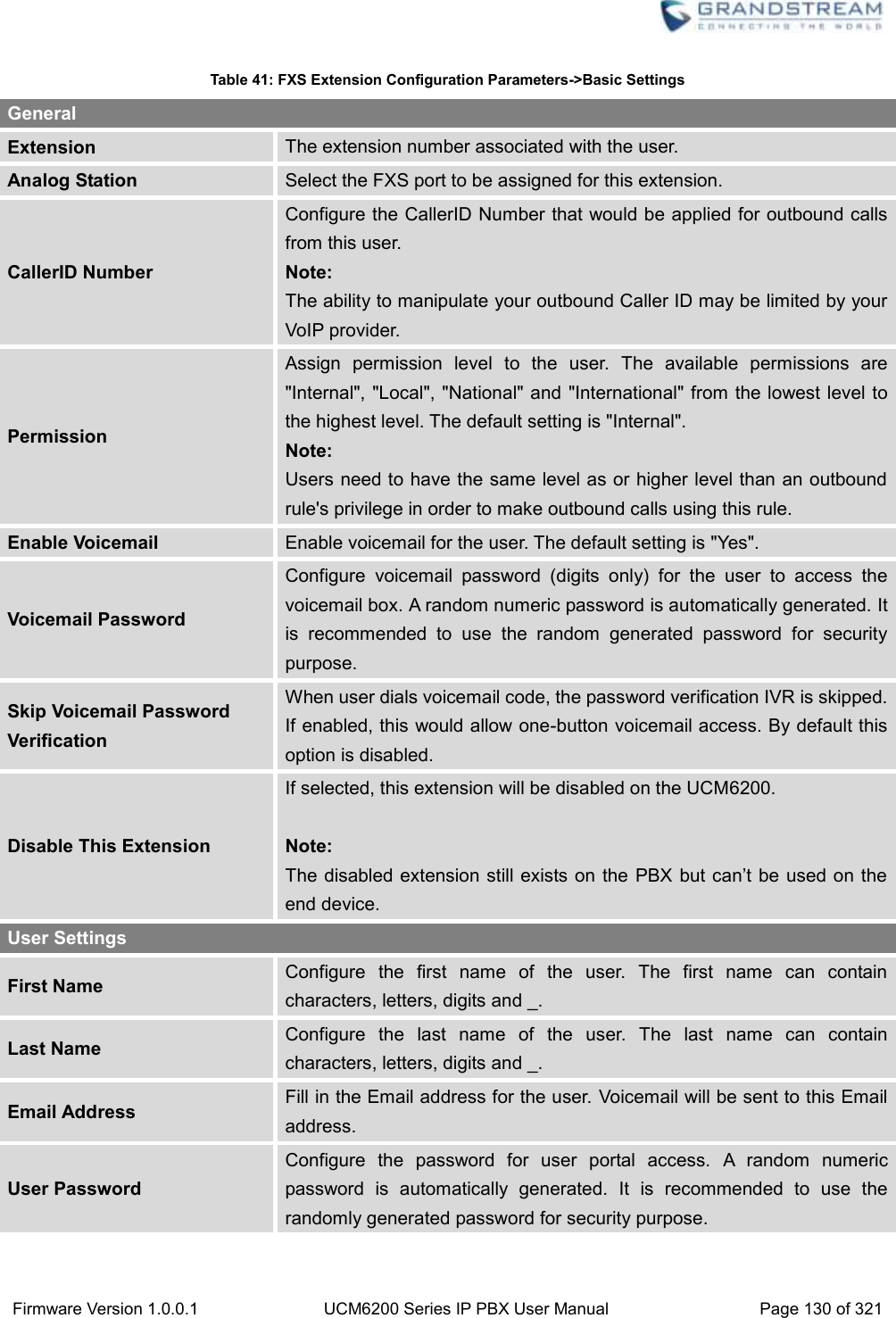
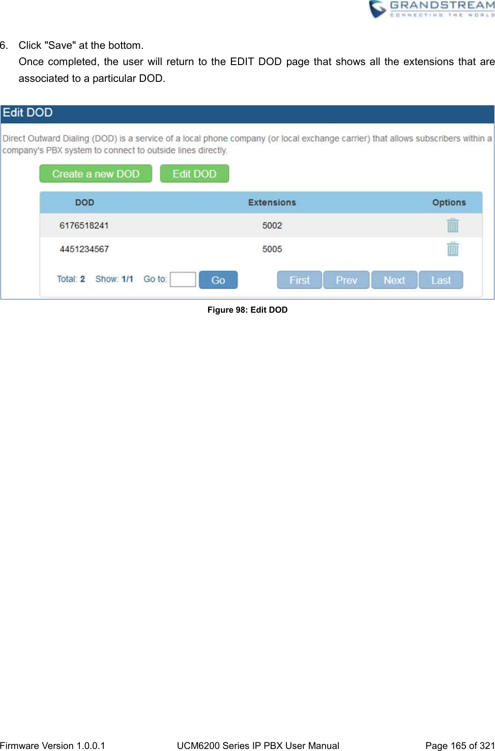
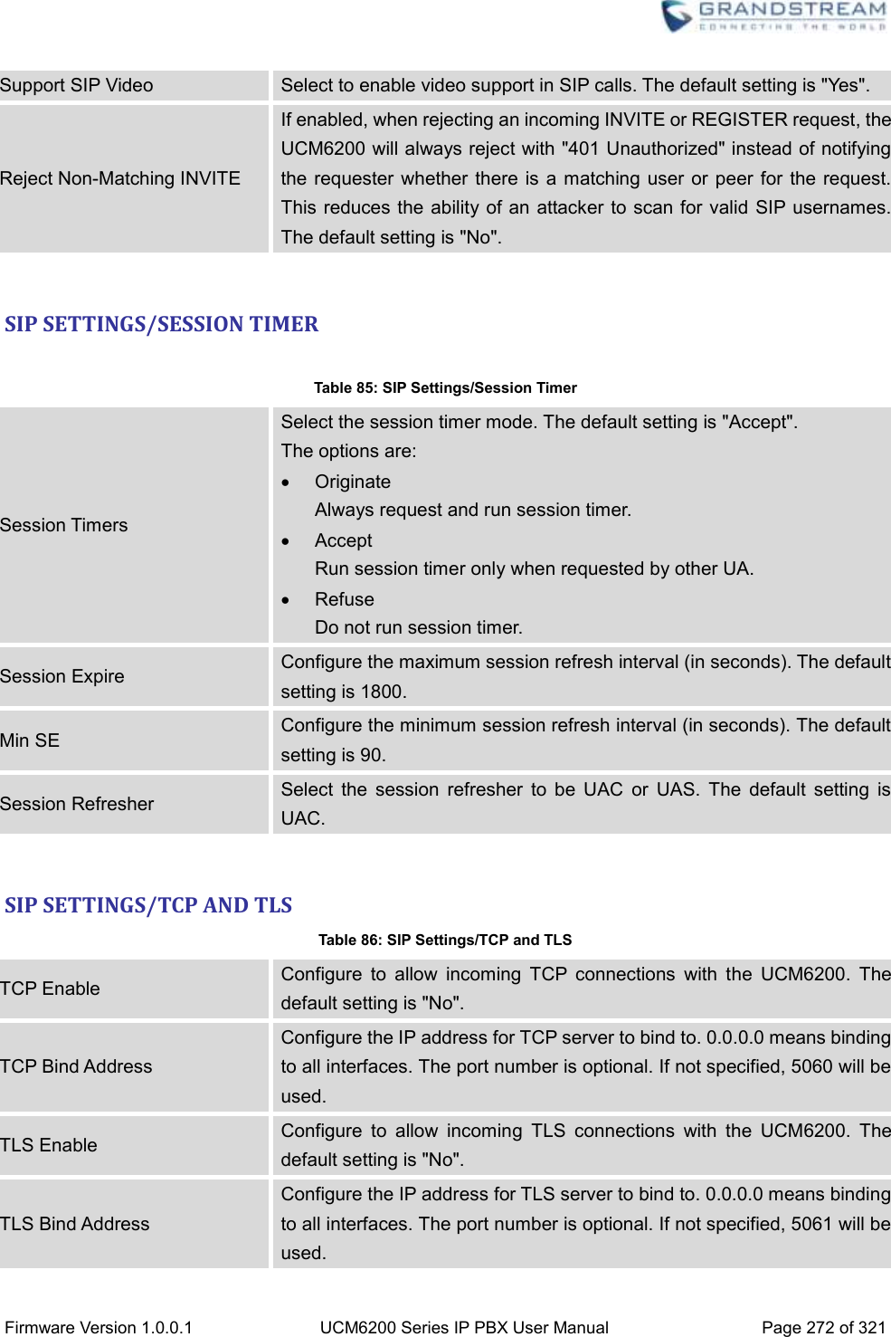
![Firmware Version 1.0.0.1 UCM6200 Series IP PBX User Manual Page 43 of 321 Figure 15: User Portal Layout For the configuration parameter information in each page, please refer to [Table 6: User Management->Create New User] for options in User Portal->Basic Information->User Information page; please refer to [EXTENSIONS] for options in User Portal->Basic Information->Extension page; please refer to [CDR] for User Portal->Basic Information->CDR page. CONCURRENT MULTI-USER LOGIN When there are multiple web UI users created, concurrent multi-user login is supported on the UCM6200. Multiple users could edit options and have configurations take effect simultaneously. However, if different users are editing the same option or making the same operation (by clicking on “Apply Changes”), a prompt will pop up as shown in the following figure. Figure 16: Multiple User Operation Error Prompt OPERATION LOG Super Admin has the authority to view operation logs on UCM6200 web GUI->Settings->User Management->Operation Log page. Operation logs list operations done by all the web UI users, for example, web UI login, creating trunk, creating outbound rule and etc. There are 6 columns to record the operation details “Date”, “User Name”, “IP Address”, “Results”, “Page Operation” and “Specific Operation”.](https://usermanual.wiki/Grandstream-Networks/UCM6202/User-Guide-3010507-Page-44.png)
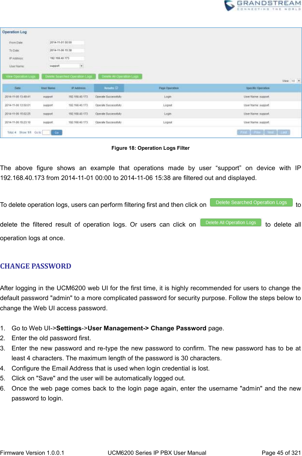
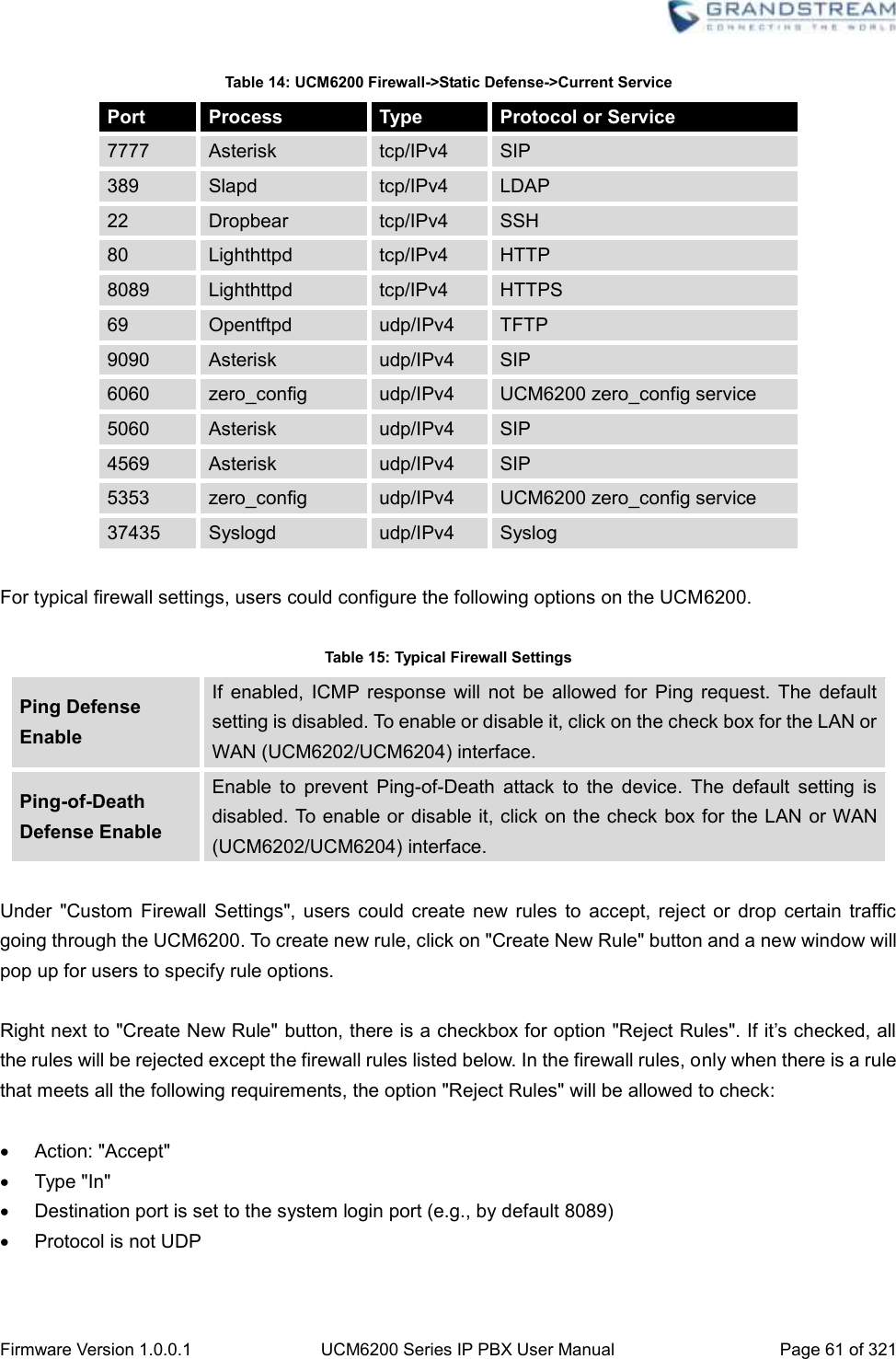
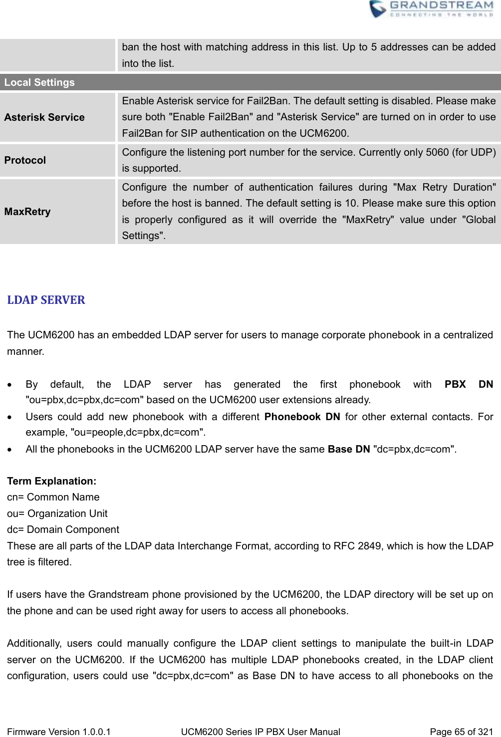
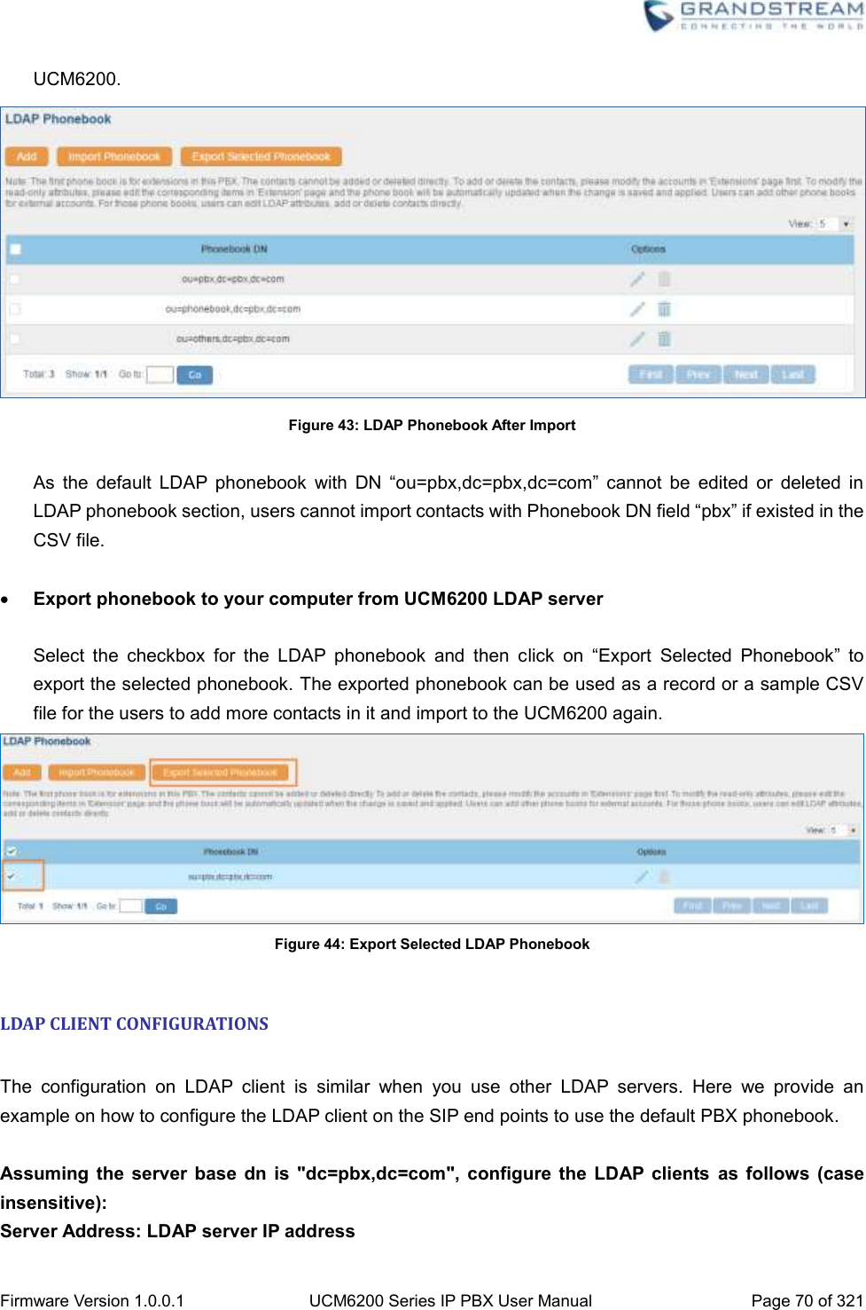
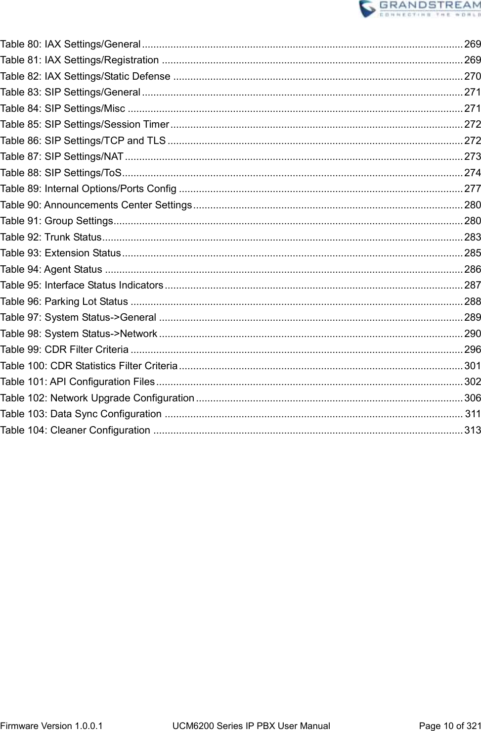
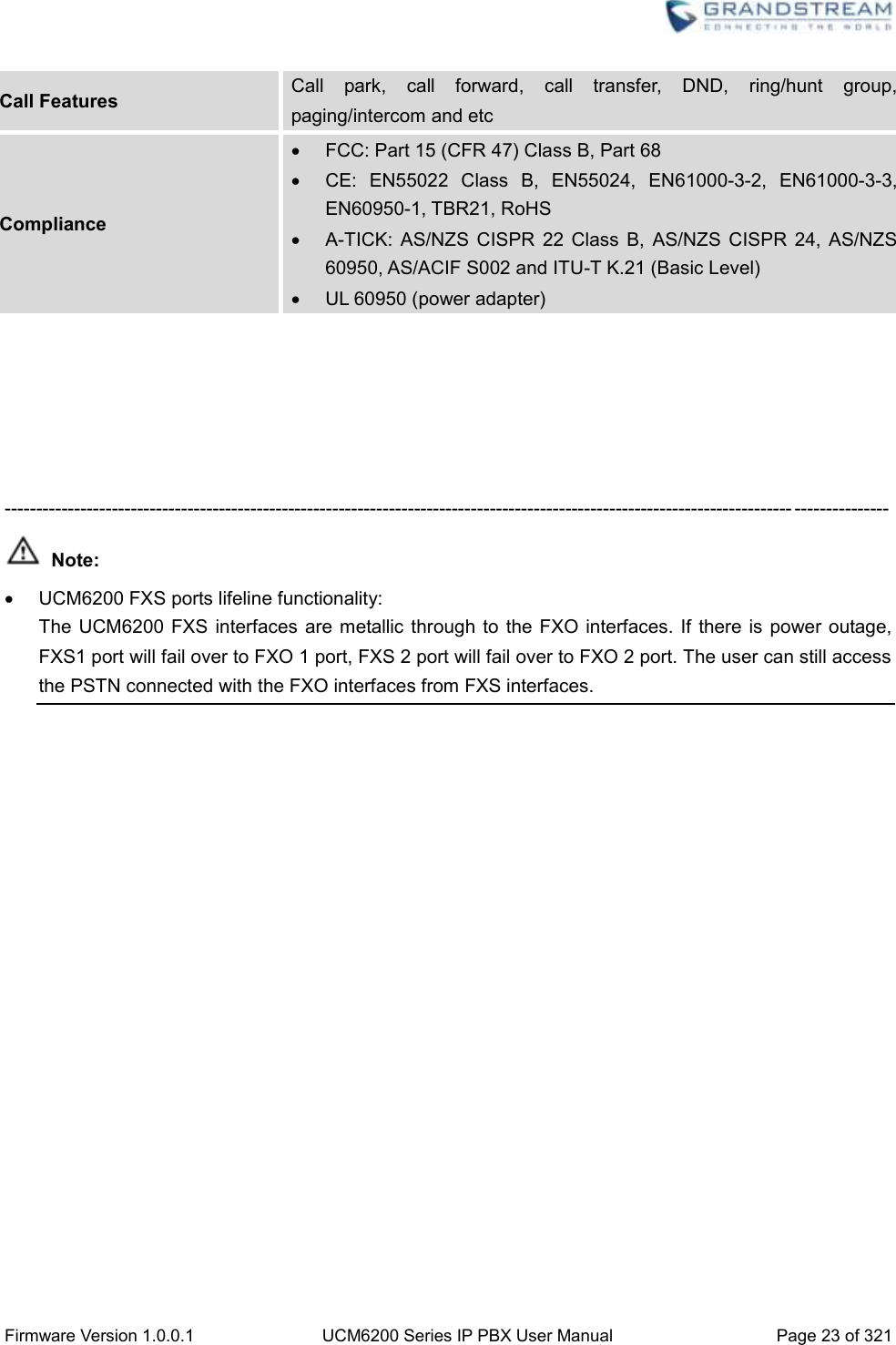
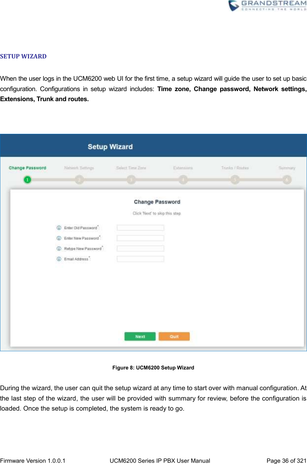
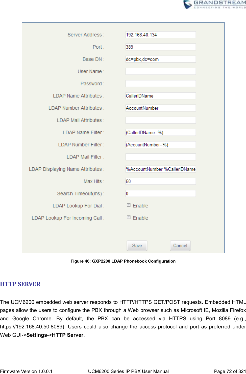
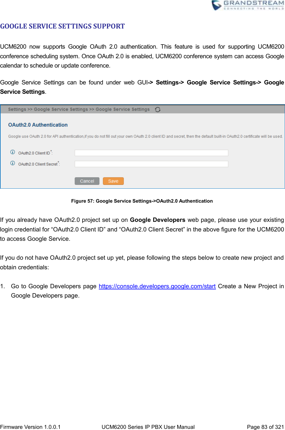
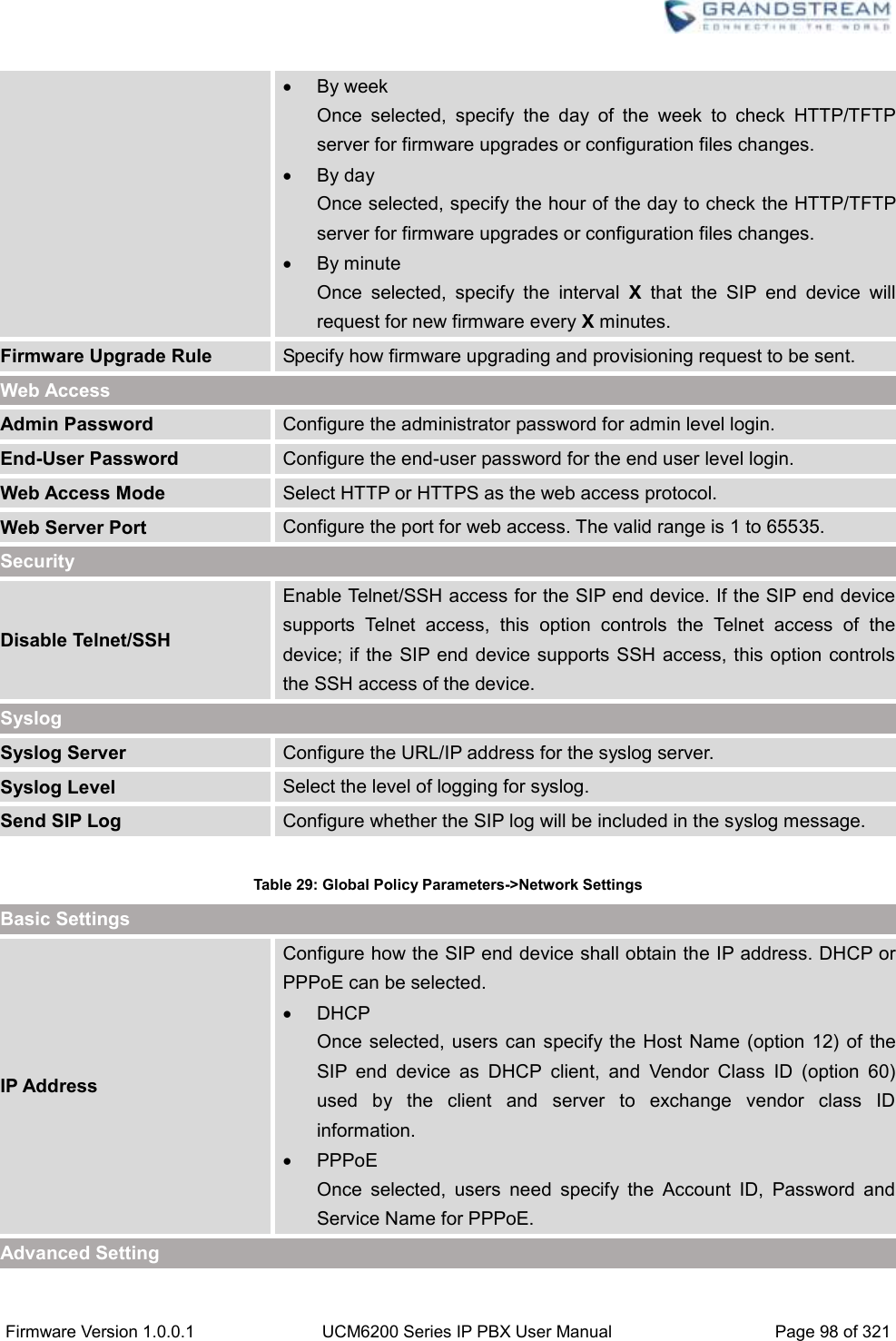
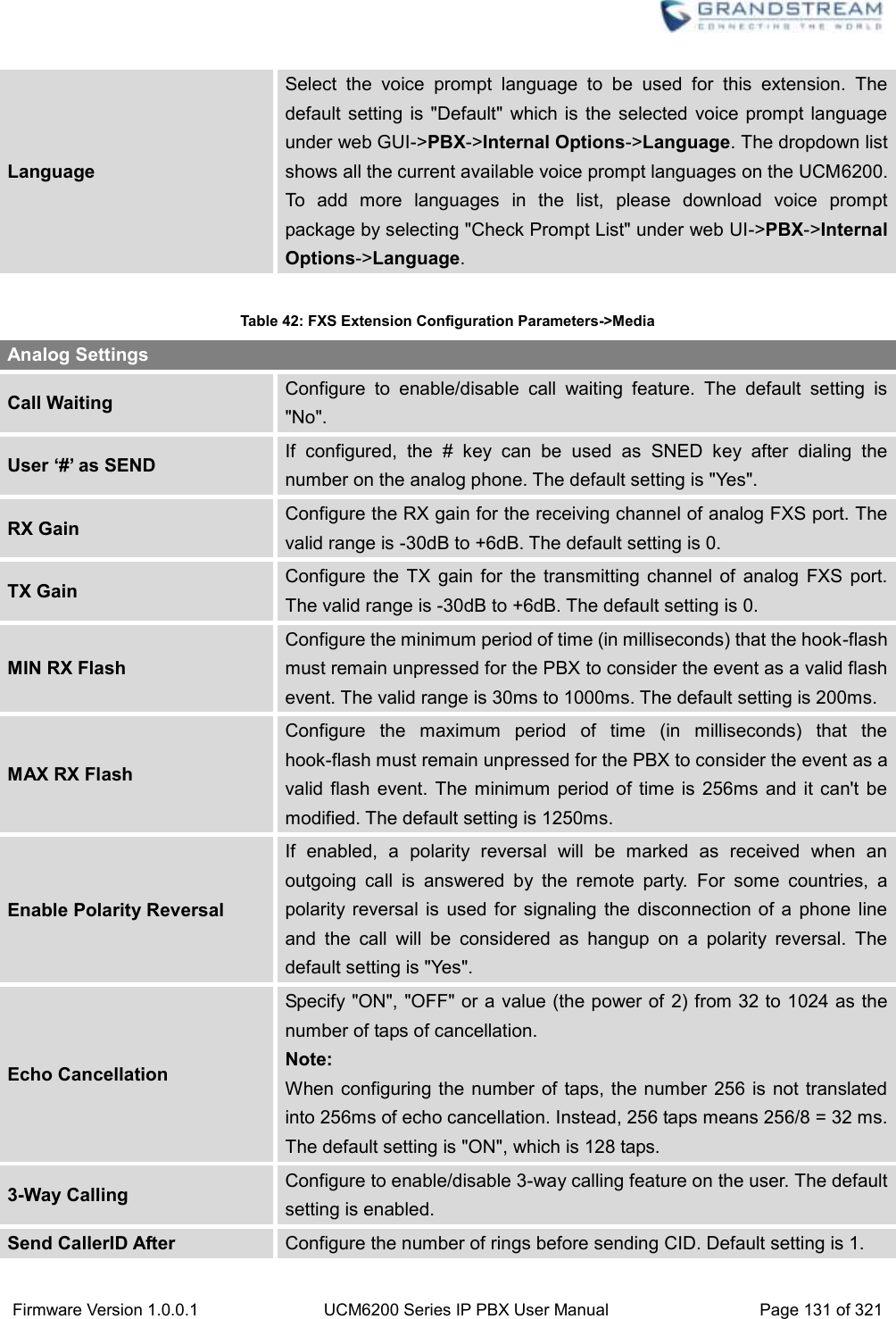
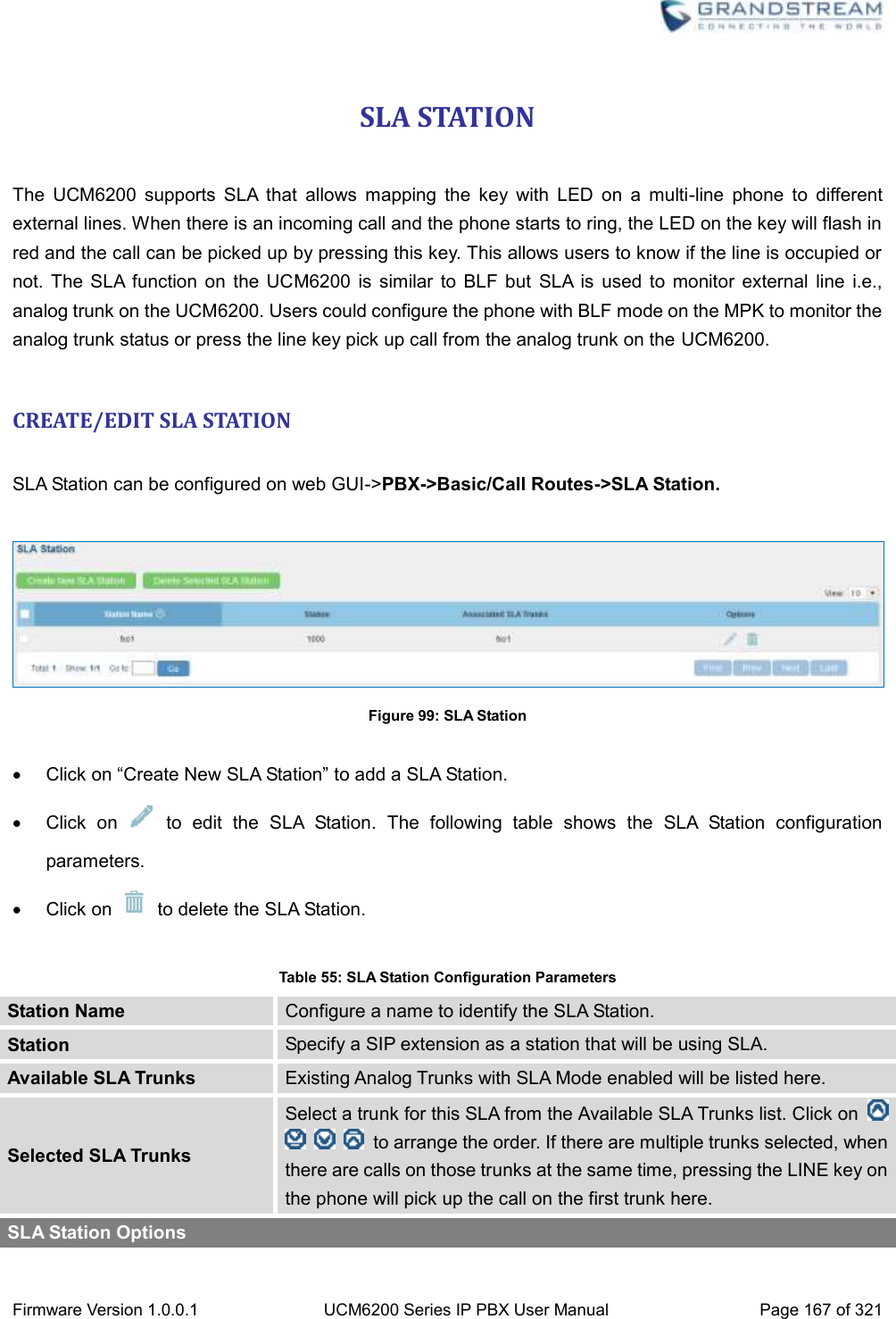
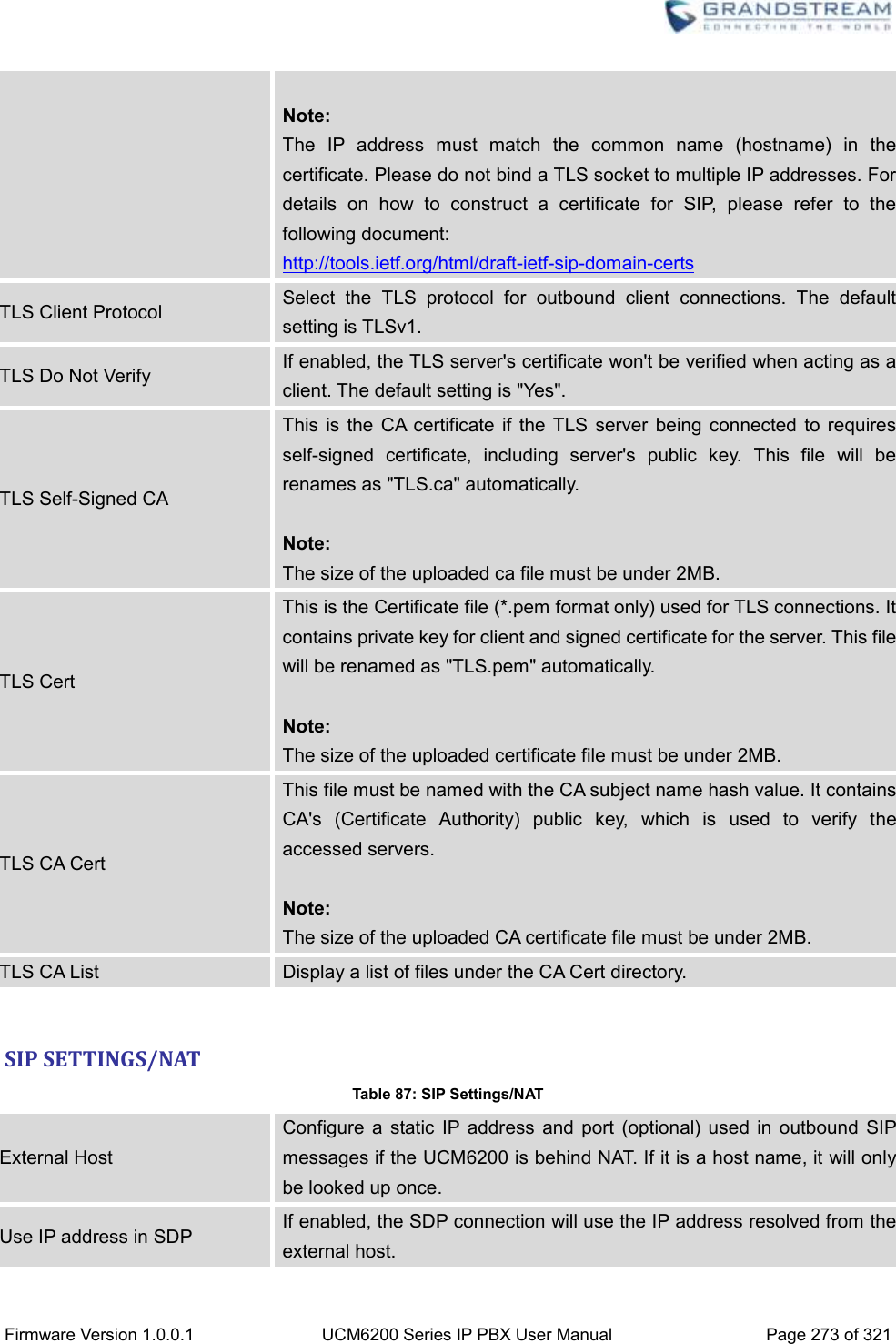
![Firmware Version 1.0.0.1 UCM6200 Series IP PBX User Manual Page 71 of 321 Base DN: dc=pbx,dc=com User Name: cn= “LDAP server login name”, dc=pbx, dc=com [matching LDAP server format] Password: “LDAP server login password” Filter: (|(CallerIDName=%)(AccountNumber=%)) Port: 389 The following figure gives a sample configurations for UCM6200 acting as a LDAP client. Figure 45: LDAP Client Configurations To configure Grandstream IP phones as the LDAP client, please refer to the following example: Server Address: The IP address or domain name of the UCM6200 Base DN: dc=pbx,dc=com User Name: Please leave this field empty Password: Please leave this field empty LDAP Name Attribute: CallerIDName Email Department FirstName LastName LDAP Number Attribute: AccountNumber MobileNumber HomeNumber Fax LDAP Number Filter: (AccountNumber=%) LDAP Name Filter: (CallerIDName=%) LDAP Display Name: AccountNumber CallerIDName LDAP Version: If existed, please select LDAP Version 3 Port: 389 The following figure shows the configuration information on a Grandstream GXP2200 to successfully use the LDAP server as configured in Figure 35: LDAP Server Configurations.](https://usermanual.wiki/Grandstream-Networks/UCM6202/User-Guide-3010507-Page-72.png)
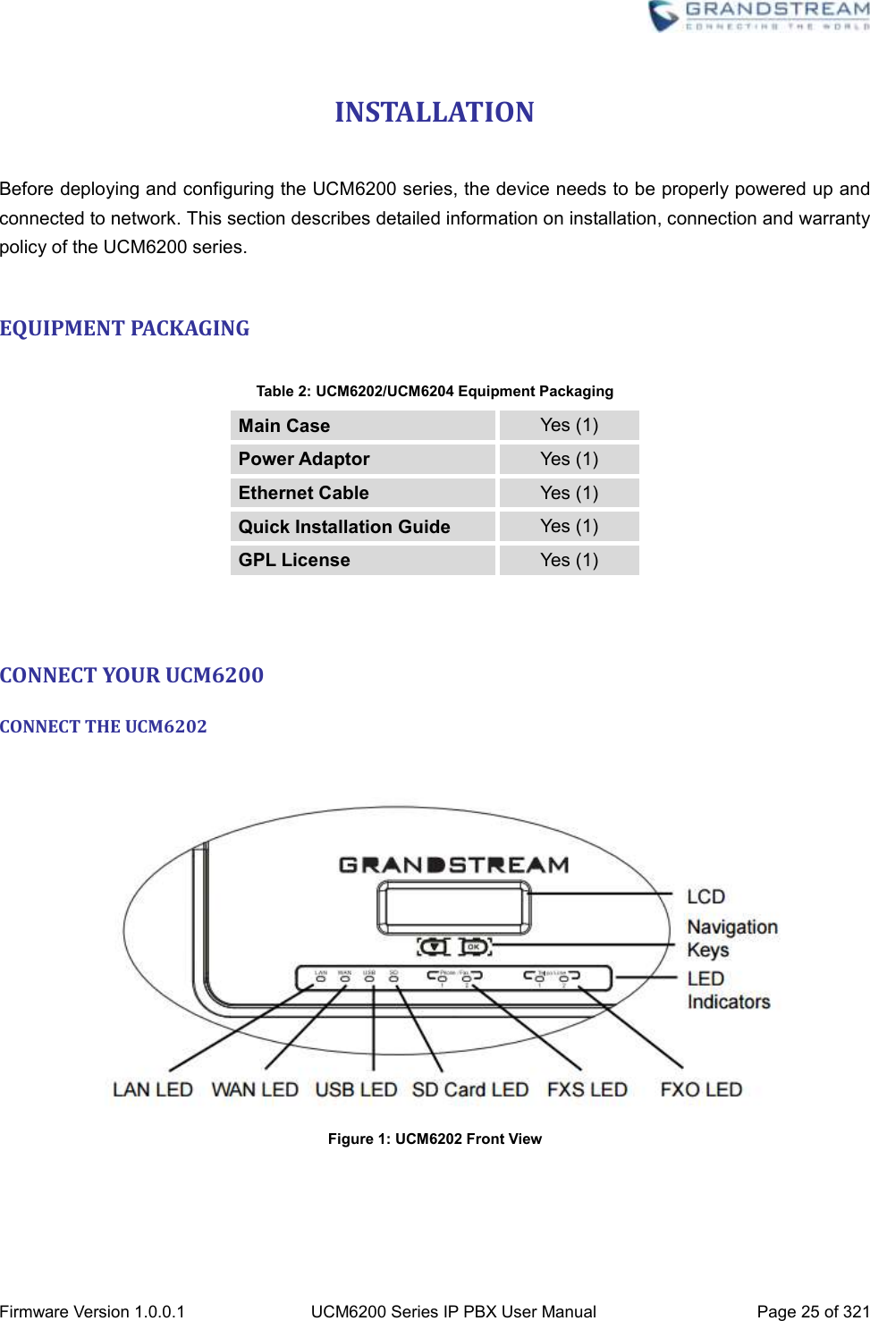
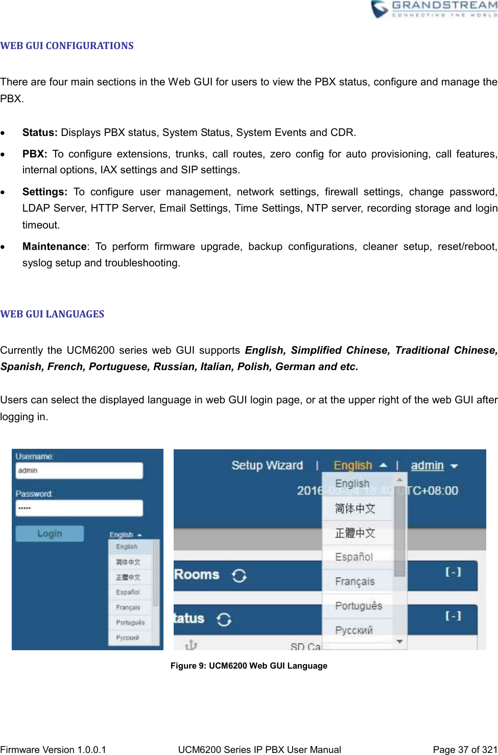
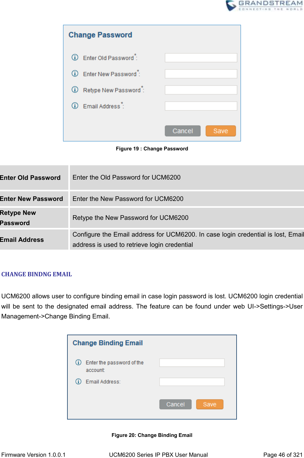
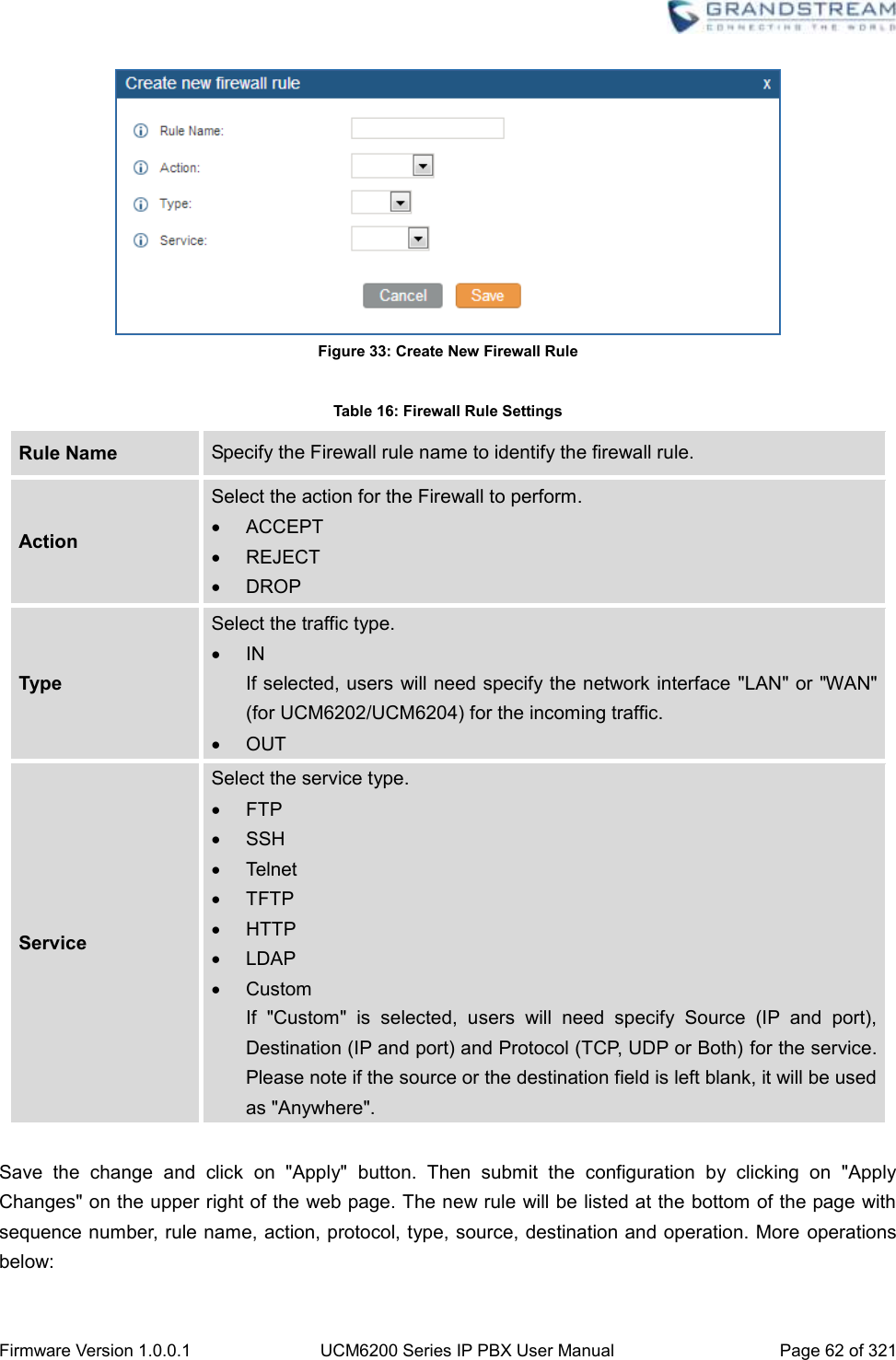
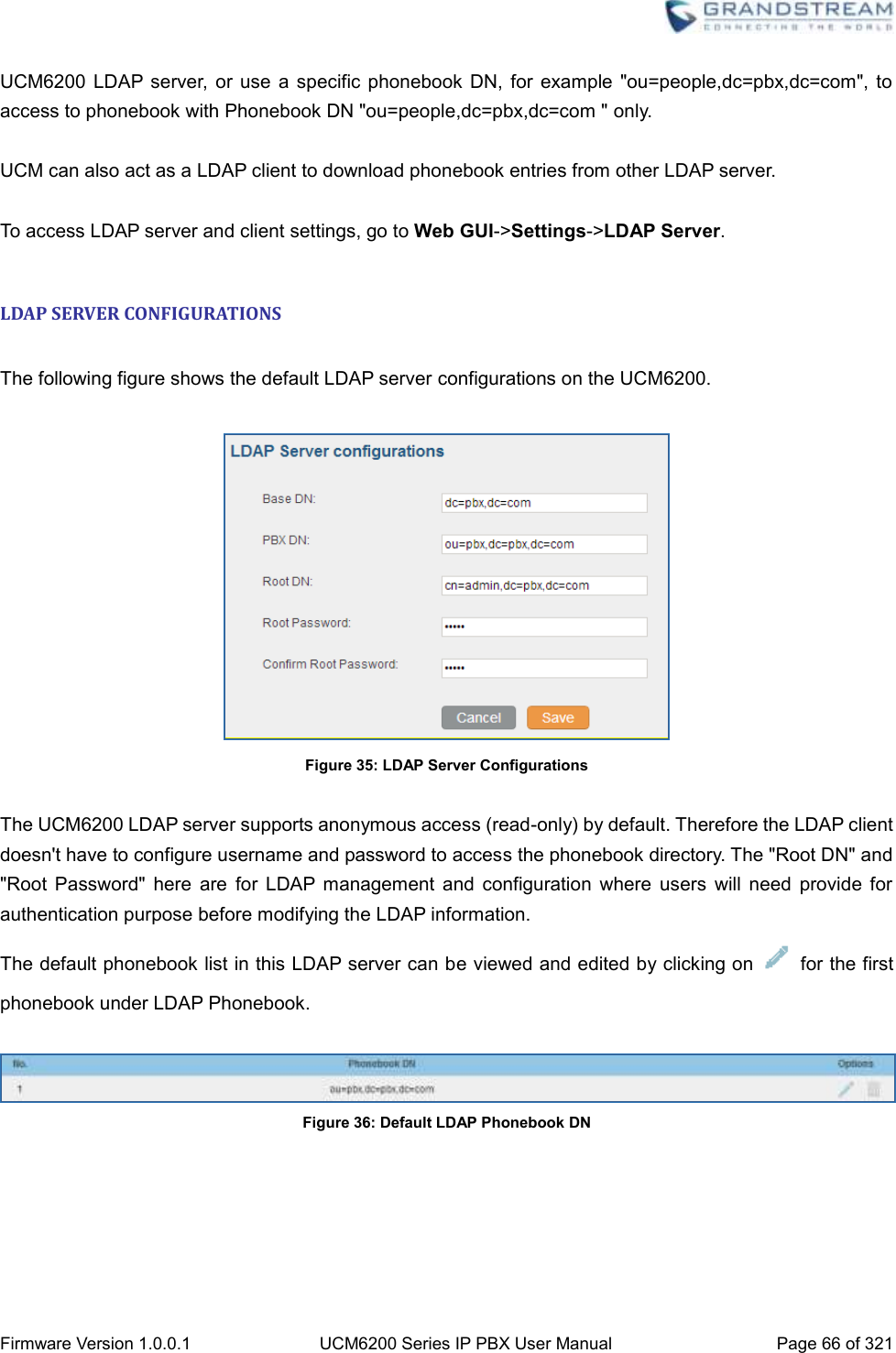
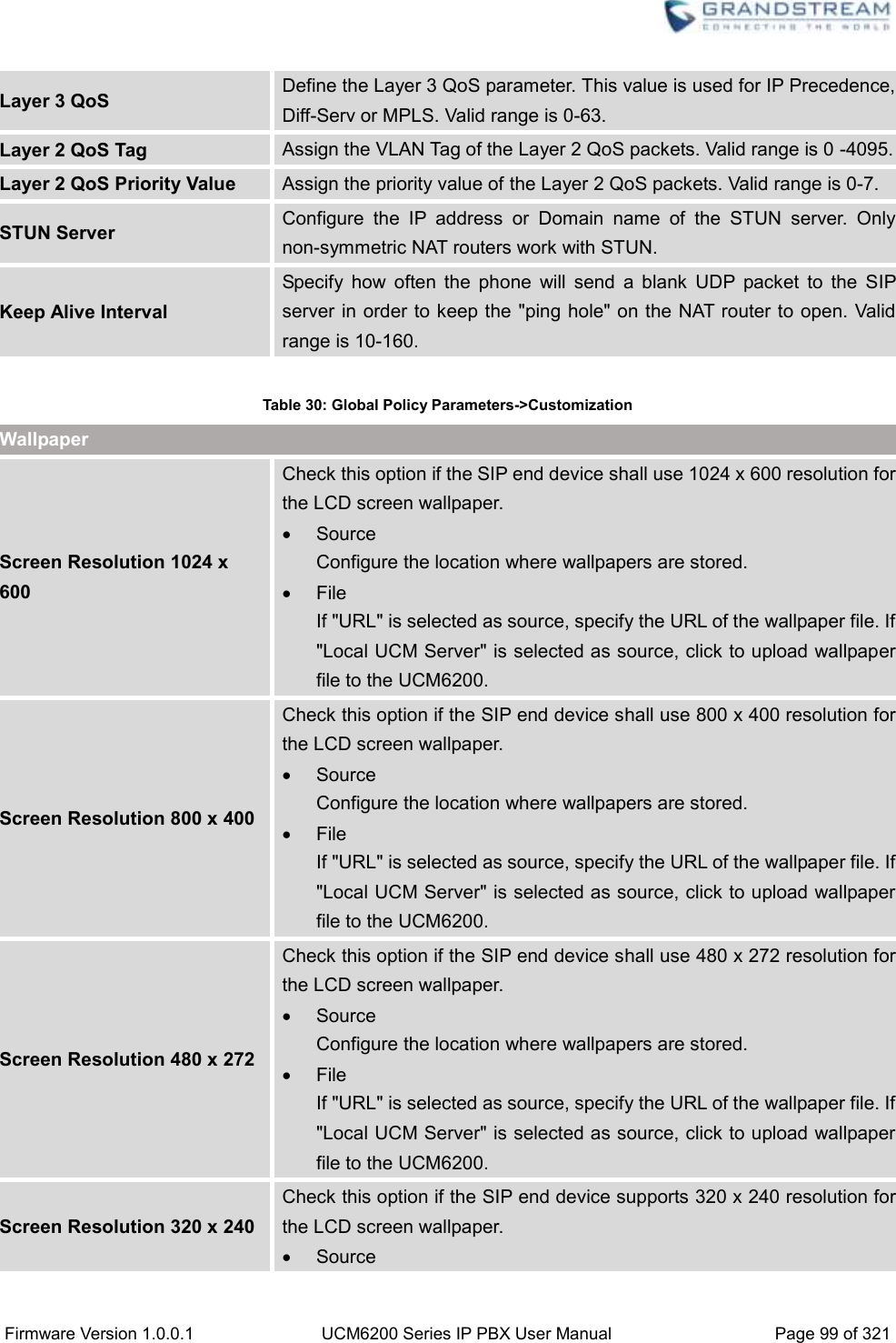
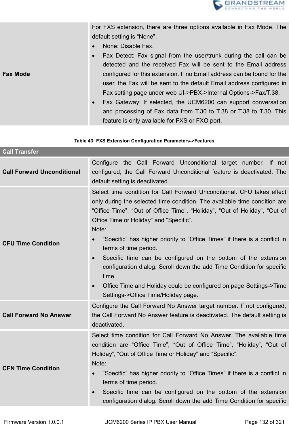
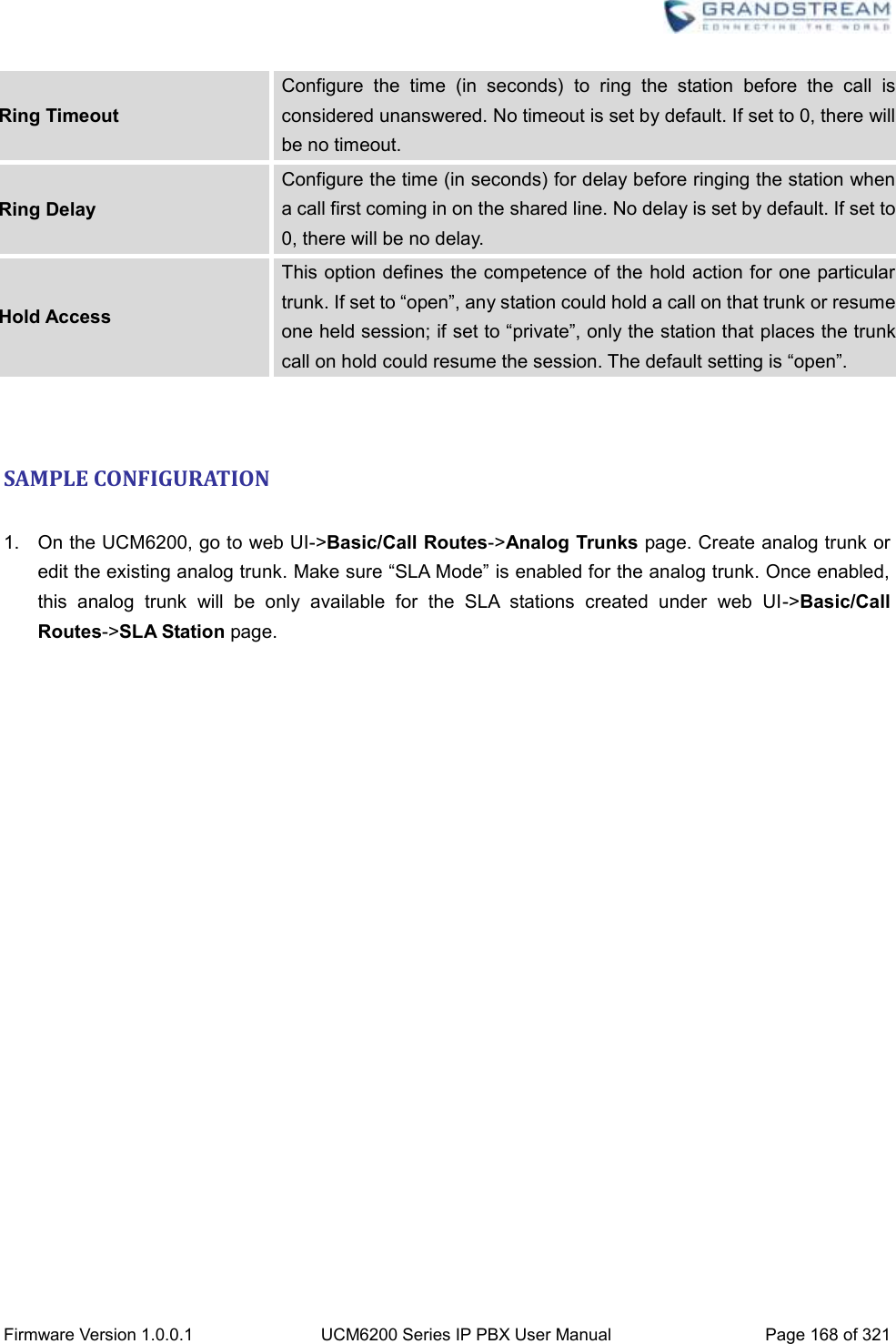
![Firmware Version 1.0.0.1 UCM6200 Series IP PBX User Manual Page 75 of 321 Table 21: Time Auto Updating Remote NTP Server Specify the URL or IP address of the NTP server for the UCM6200 to synchronize the date and time. The default NTP server is ntp.ipvideotalk.com. Enable DHCP Option 2 If set to "Yes", the UCM6200 is allowed to get provisioned for Time Zone from DHCP Option 2 in the local server automatically. The default setting is "Yes". Enable DHCP Option 42 If set to "Yes", the UCM6200 is allowed to get provisioned for NTP Server from DHCP Option 42 in the local server automatically. This will override the manually configured NTP Server. The default setting is "Yes". Time Zone Select the proper time zone option so the UCM6200 can display correct time accordingly. If "Self-Defined Tome Zone" is selected, please specify the time zone parameters in "Self-Defined Time Zone" field as described in below option. Self-Defined Time Zone If "Self-Defined Time Zone" is selected in "Time Zone" option, users will need define their own time zone following the format below. The syntax is: std offset dst [offset], start [/time], end [/time] Default is set to: MTZ+6MDT+5,M4.1.0,M11.1.0 MTZ+6MDT+5 This indicates a time zone with 6 hours offset and 1 hour ahead for DST, which is U.S central time. If it is positive (+), the local time zone is west of the Prime Meridian (A.K.A: International or Greenwich Meridian); If it is negative (-), the local time zone is east. M4.1.0,M11.1.0 The 1st number indicates Month: 1,2,3.., 12 (for Jan, Feb, .., Dec). The 2nd number indicates the nth iteration of the weekday: (1st Sunday, 3rd Tuesday…). Normally 1, 2, 3, 4 are used. If 5 is used, it means the last iteration of the weekday. The 3rd number indicates weekday: 0,1,2,..,6 ( for Sun, Mon, Tues, ... ,Sat). Therefore, this example is the DST which starts from the First Sunday of April to the 1st Sunday of November.](https://usermanual.wiki/Grandstream-Networks/UCM6202/User-Guide-3010507-Page-76.png)

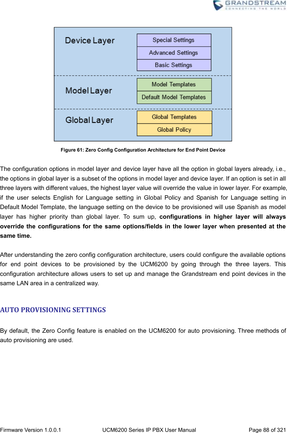
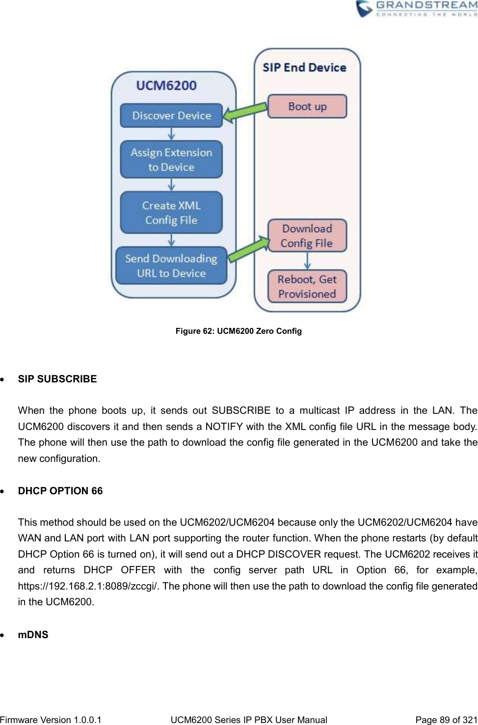
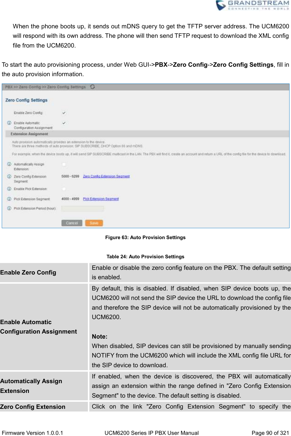
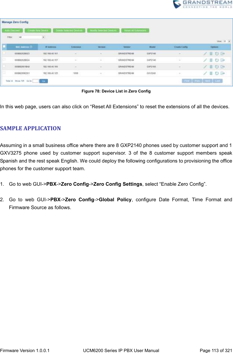
![Firmware Version 1.0.0.1 UCM6200 Series IP PBX User Manual Page 87 of 321 PROVISIONING OVERVIEW Grandstream SIP Devices can be configured via Web interface as well as via configuration file through TFTP/HTTP/HTTPS download. All Grandstream SIP devices support a proprietary binary format configuration file and XML format configuration file. The UCM6200 provides a Plug and Play mechanism to auto-provision the Grandstream SIP devices in a zero configuration manner by generating XML config file and having the phone to download it within LAN area. This allows users to finish the installation with ease and start using the SIP devices in a managed way. To provision a phone, three steps are involved, i.e., discovery, configuration and provisioning. This section explains how Zero Config works on the UCM6200. The settings for this feature can be accessed via Web UI->PBX->Zero Config. CONFIGURATION ARCHITECTURE FOR END POINT DEVICE Started from firmware version 1.0.7.10, the end point device configuration in zero config is divided into the following three layers with priority from the lowest to the highest: Global This is the lowest layer. Users can configure the most basic options that could apply to all Grandstream SIP devices during provisioning via Zero config. Model In this layer, users can define model-specific options for the configuration template. Device This is the highest layer. Users can configure device-specific options for the configuration for individual device here. Each layer also has its own structure in different levels. Please see figure below. The details for each layer are explained in sections [GLOBAL CONFIGURATION], [MODEL CONFIGURATION] and [DEVICE CONFIGURATION].](https://usermanual.wiki/Grandstream-Networks/UCM6202/User-Guide-3010507-Page-88.png)
![Firmware Version 1.0.0.1 UCM6200 Series IP PBX User Manual Page 94 of 321 Table 26: Global Policy Parameters->Phone Settings Default Call Settings Dial Plan Configure the default dial plan rule. For syntax and examples, please refer to user manual of the SIP devices to be provisioned for more details. Enable Call Features When enabled, “Do Not Disturb”, “Call Forward” and other call features can be used via the local feature code on the phone. Otherwise, the ITSP feature code will be used. Use # as Dial Key If set to “Yes”, pressing the number key “#” will immediately dial out the input digits. Auto Answer by Call-info If set to "Yes", the phone will automatically turn on the speaker phone to answer incoming calls after a short reminding beep, based on the SIP Call-Info header sent from the server/proxy. The default setting is enabled. NAT Traversal Configure which NAT traversal mechanism will be enabled on the endpoint device. If set to "STUN" and STUN server is configured, the phone system will periodically send STUN message to the SUTN server to get the public IP address of its NAT environment and keep the NAT port open. STUN will not work if the NAT is symmetric type. If set to “Keep-alive”, the phone system will send the STUN packets to maintain the connection that is first established during registration of the phone. The “Keep-alive” packets will fool the NAT device into keeping the connection open and this allows the host server to send SIP requests directly to the registered phone. If it needs to use OpenVPN to connect host server, it needs to set it to “VPN”. If the firewall and the SIP device behind the firewall are both able to use UPNP, it can be set to “UPNP”. The both parties will negotiate to use which port to allow SIP through. The default setting is "Keep-alive". Use Random Port Configure whether to allow the endpoint device to use random ports for both SIP and RTP messages. This is usually necessary when multiple phones are behind the same full cone NAT. The default setting is "No". Note: This parameter must be set to "No" for Direct IP Calling to work. General Settings Call Progress Tones Configure call progress tones including ring tone, dial tone, second dial tone, message waiting tone, ring back tone, call waiting tone, busy tone and reorder tone using the following syntax: f1=val, f2=val[, c=on1/ off1[- on2/ off2[- on3/ off3]]];](https://usermanual.wiki/Grandstream-Networks/UCM6202/User-Guide-3010507-Page-95.png)
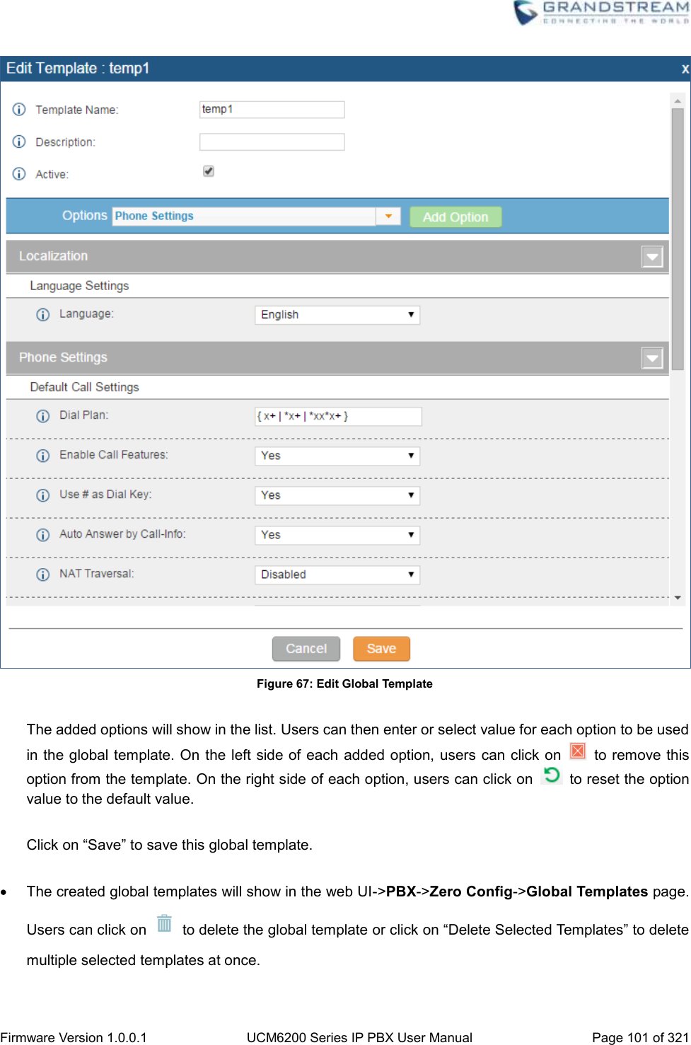
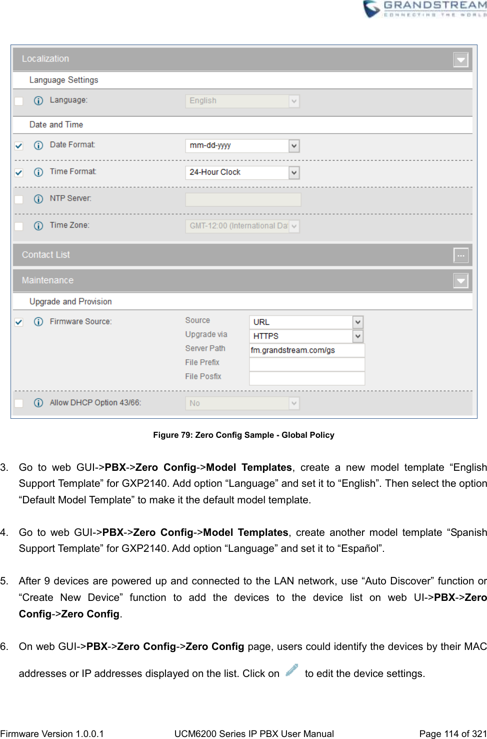
![Firmware Version 1.0.0.1 UCM6200 Series IP PBX User Manual Page 100 of 321 Configure the location where wallpapers are stored. File If "URL" is selected as source, specify the URL of the wallpaper file. If "Local UCM Server" is selected as source, click to upload wallpaper file to the UCM6200. GLOBAL TEMPLATES Global Templates can be accessed in web GUI->PBX->Zero Config->Global Templates. Users can create multiple global templates with different sets of configurations and save the templates. Later on, when the user configures the device in Edit Device dialog->Advanced Settings, the user can select to use one of the global template for the device. Please refer to section [MANAGE DEVICES] for more details on using the global templates. When creating global template, users can select the categories and the parameters under each category to be used in the template. The global policy and the selected global template will both take effect when generating the config file. However, the selected global template has higher priority to the global policy when it comes to the same setting option/field. If the same option/field has different value configured in the global policy and the selected global template, the value for this option/field in the selected global template will override the value in global policy. Click on "Create New Template" to add a global template. Users will see the following configurations. Table 31: Create New Template Template Name Create a name to identify this global template. Description Provide a description for the global template. This is optional. Active Check this option to enable the global template. Click on to edit the global template. The window for editing global template is shown in the following figure. In the “Options” field, after entering the option name key word, the options containing the key word will be listed. Users could then select the options to be modified and click on “Add Option” to add it into the global template.](https://usermanual.wiki/Grandstream-Networks/UCM6202/User-Guide-3010507-Page-101.png)
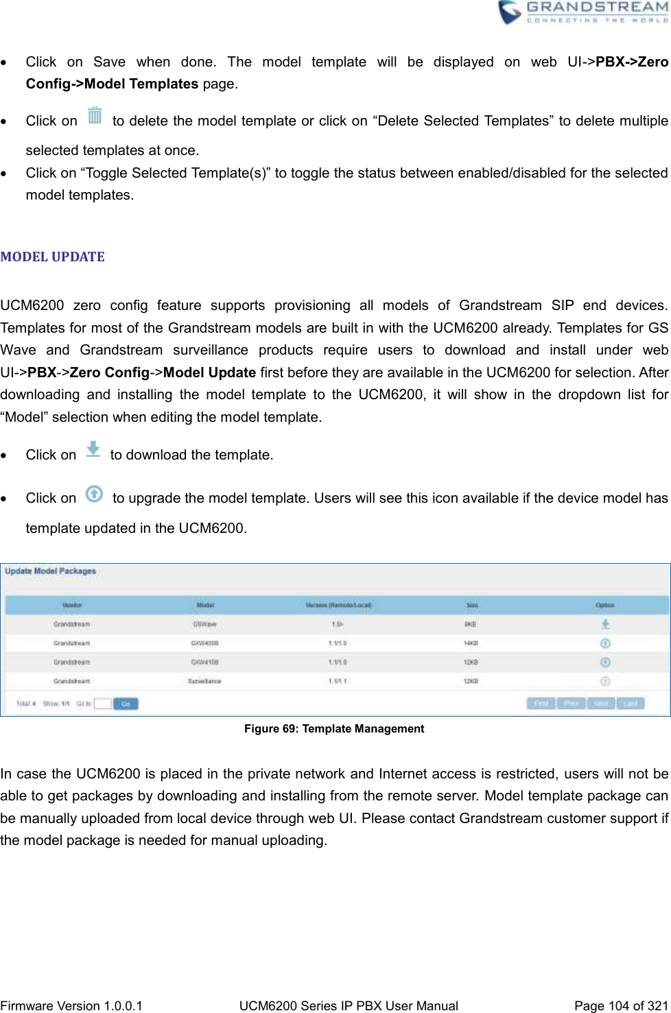
![Firmware Version 1.0.0.1 UCM6200 Series IP PBX User Manual Page 102 of 321 Click on “Toggle Selected Template(s)” to toggle the status between enabled/disabled for the selected templates. MODEL CONFIGURATION MODEL TEMPLATES Model layer configuration allows users to apply model-specific configurations to different devices. Users could create/edit/delete a model template by accessing web GUI, page PBX->Zero Config->Model Templates. If multiple model templates are created and enabled, when the user configures the device in Edit Device dialog->Advanced Settings, the user can select to use one of the model template for the device. Please refer to section [MANAGE DEVICES] for more details on using the model template. For each created model template, users can assign it as default model template. If assigned as default model template, the values in this model template will be applied to all the devices of this model. There is always only one default model template that can be assigned at one time on the UCM6200. The selected model template and the default model template will both take effect when generating the config file for the device. However, the model template has higher priority to default model template when it comes to the same setting option/field. If the same option/field has different value configured in the default model template and the selected model template, the value for this option/field in the selected model template will override the value in default model template. Click on “Create New Template” to add a model template. Table 32: Create New Model Template Model Select a model to apply this template. The supported Grandstream models are listed in the dropdown list for selection. Template Name Create a name for the model template. Description Enter a description for the model template. This is optional. Default Model Template Select to assign this model template as the default model template. The value of the option in default model template will be overridden if other selected model template has a different value for the same option. Active Check this option to enable the model template. Click on to edit the model template.](https://usermanual.wiki/Grandstream-Networks/UCM6202/User-Guide-3010507-Page-103.png)

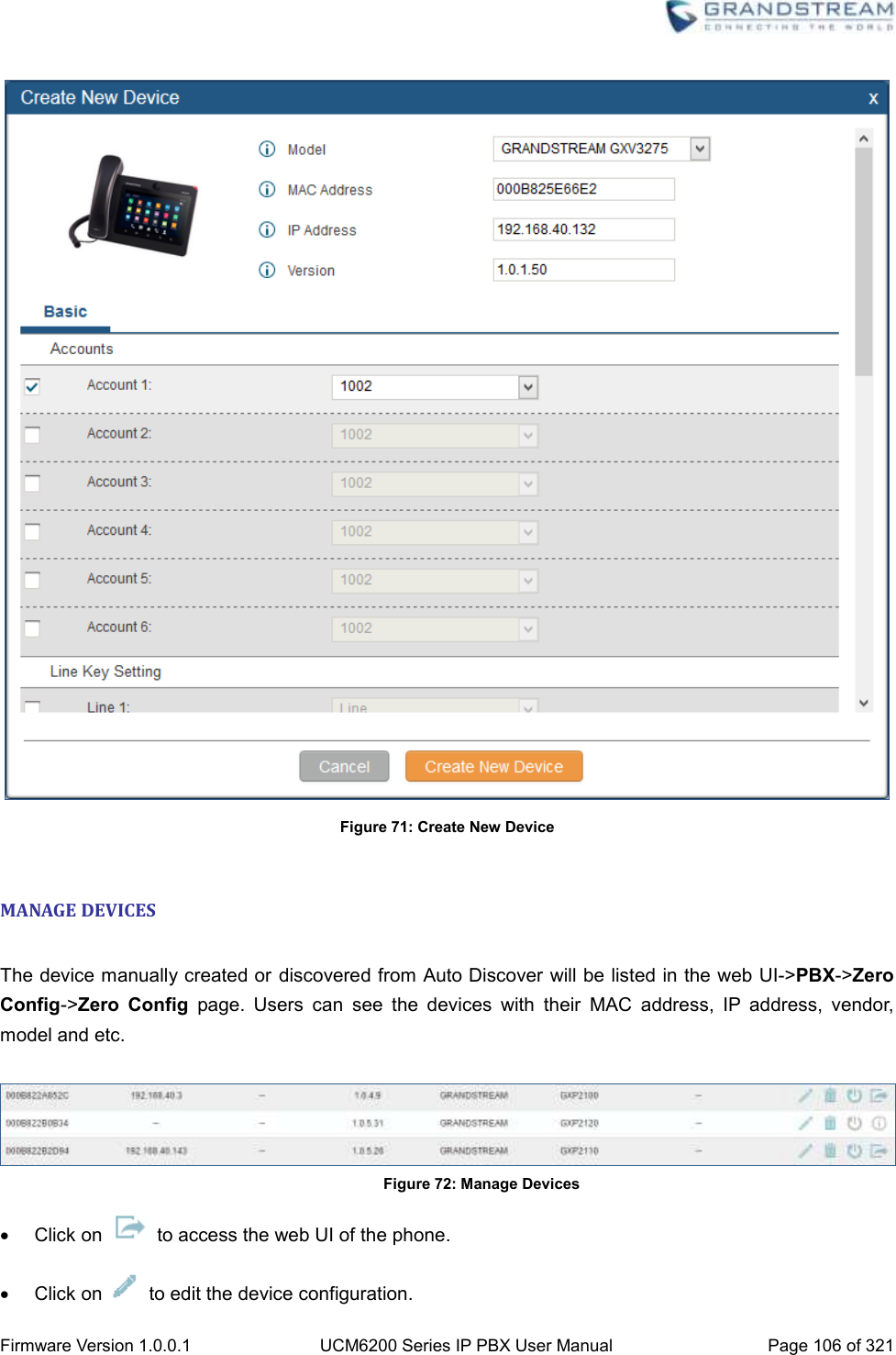
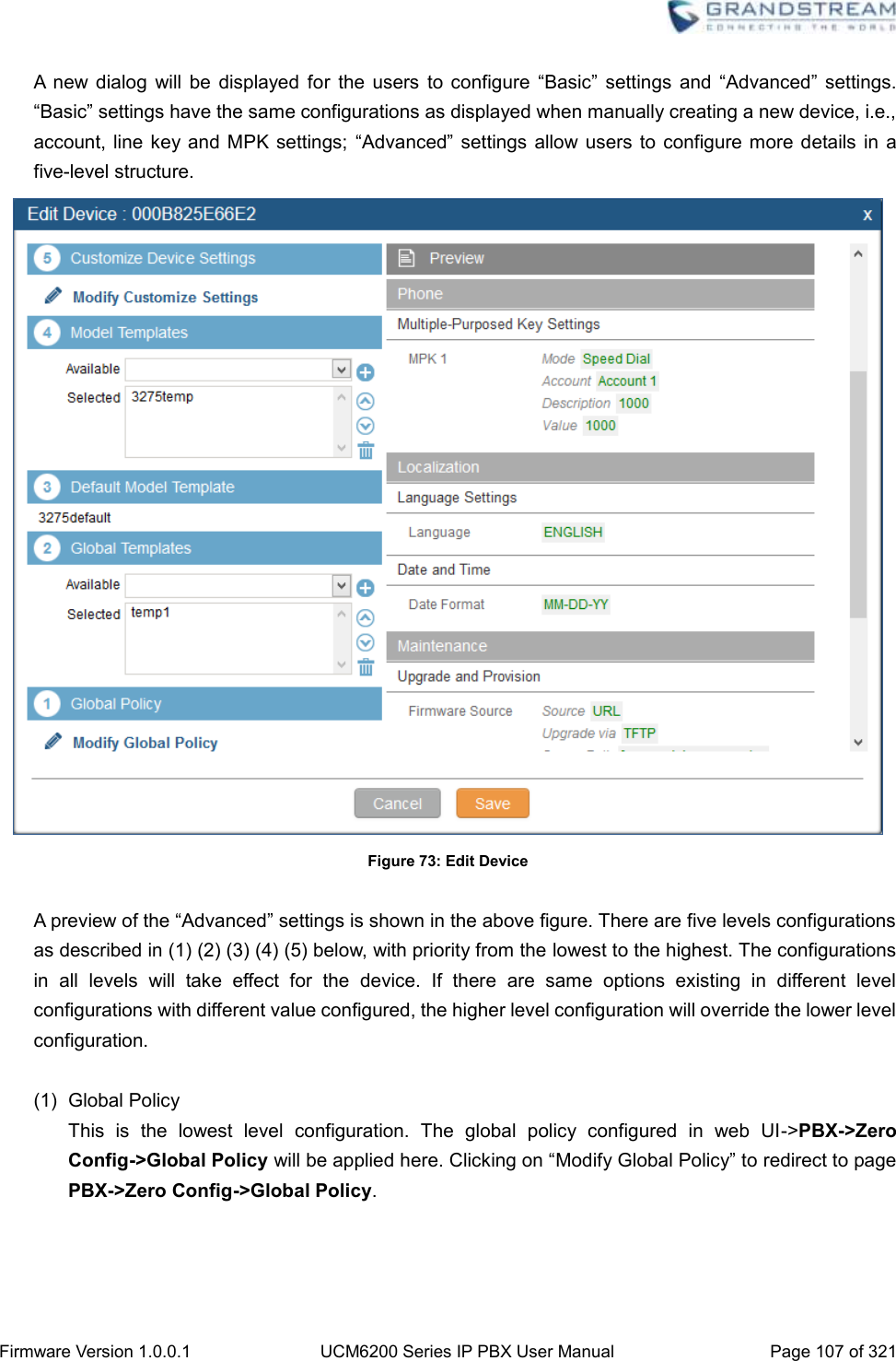
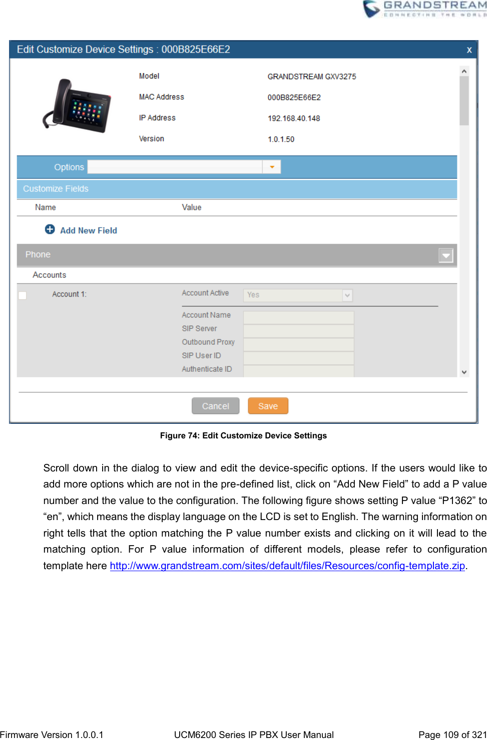
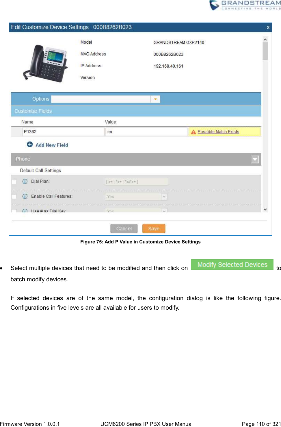
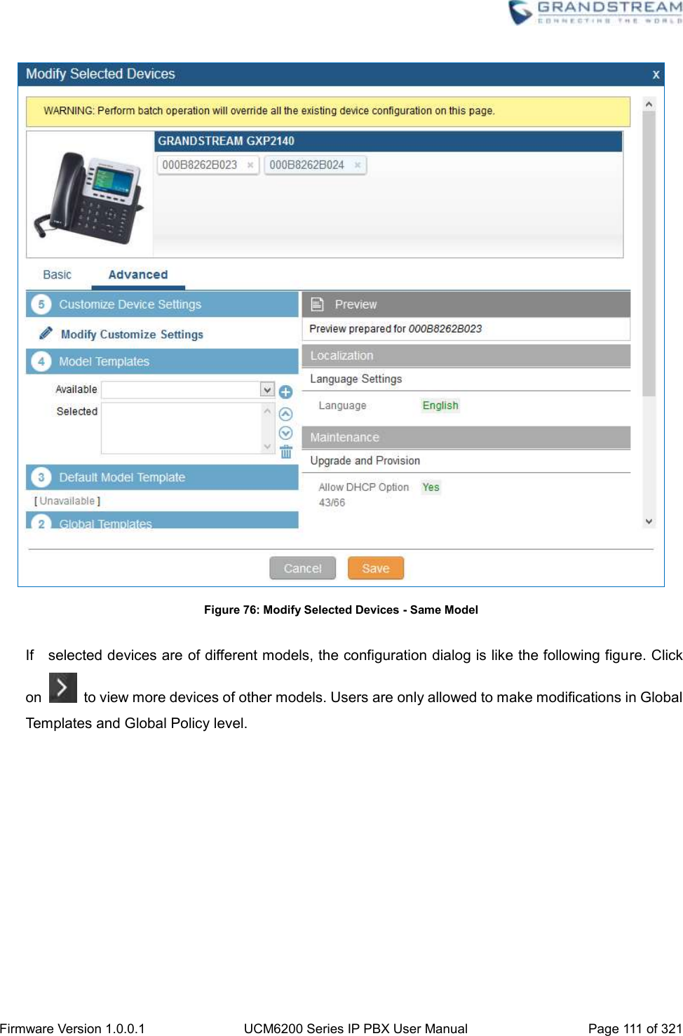
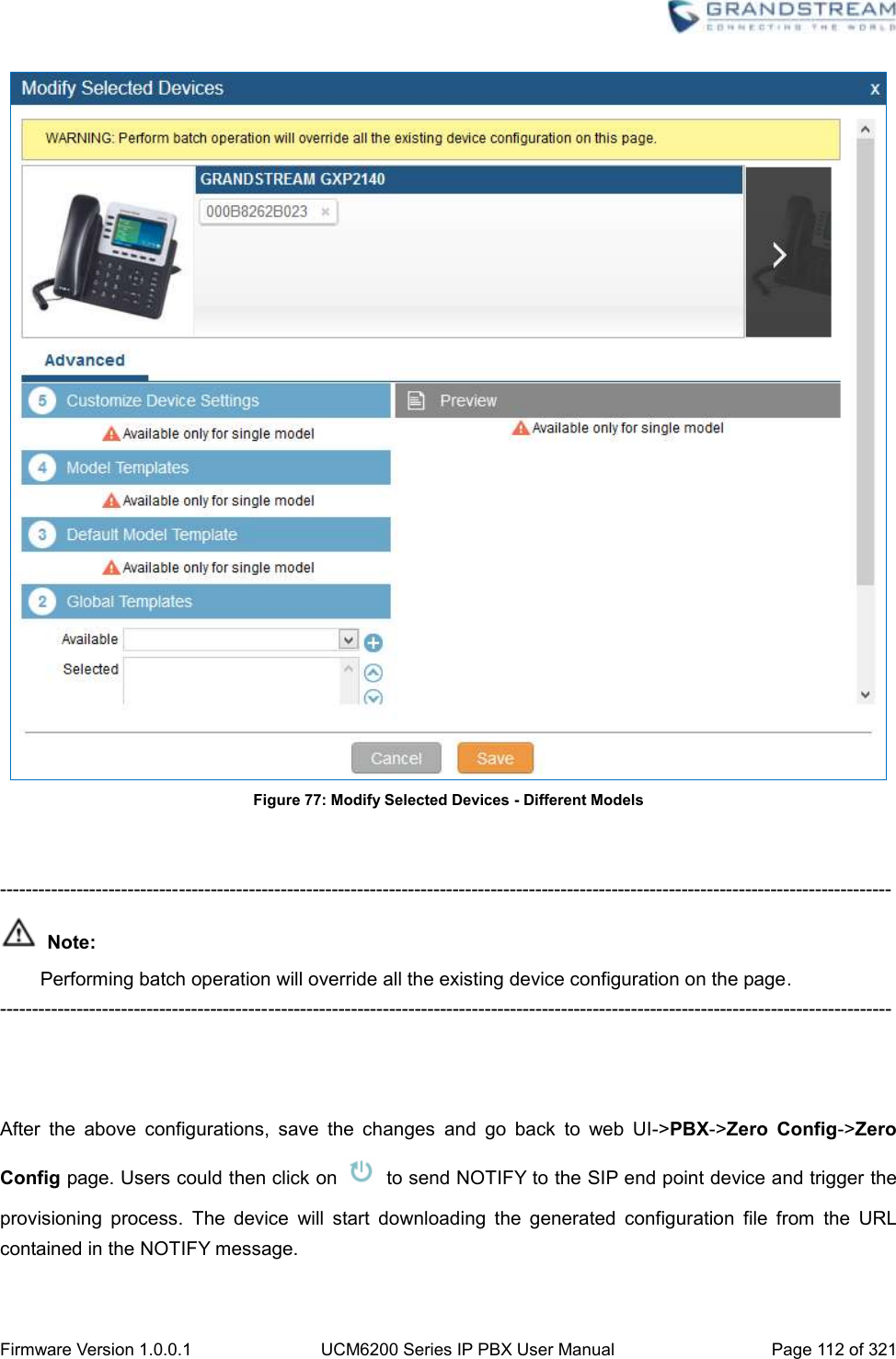
![Firmware Version 1.0.0.1 UCM6200 Series IP PBX User Manual Page 108 of 321 (2) Global Templates Select a global template to be used for the device and click on to add. Multiple global templates can be selected and users can arrange the priority by adjusting orders via and . All the selected global templates will take effect. If the same option exists on multiple selected global templates, the value in the template with higher priority will override the one in the template with lower priority. Click on to remove the global template from the selected list. (3) Default Model Template Default Model Template will be applied to the devices of this model. Default model template can be configured in model template under web UI->PBX->Zero Config->Model Templates page. Please see default model template option in [Table 32: Create New Model Template]. (4) Model Templates Select a model template to be used for the device and click on to add. Multiple global templates can be selected and users can arrange the priority by adjusting orders via and . All the selected model templates will take effect. If the same option exists on multiple selected model templates, the value in the template with higher priority will override the one in the template with lower priority. Click on to remove the model template from the selected list. (5) Customize Device Settings This is the highest level configuration for the device. Click on “Modify Customize Device Settings” and following dialog will show.](https://usermanual.wiki/Grandstream-Networks/UCM6202/User-Guide-3010507-Page-109.png)


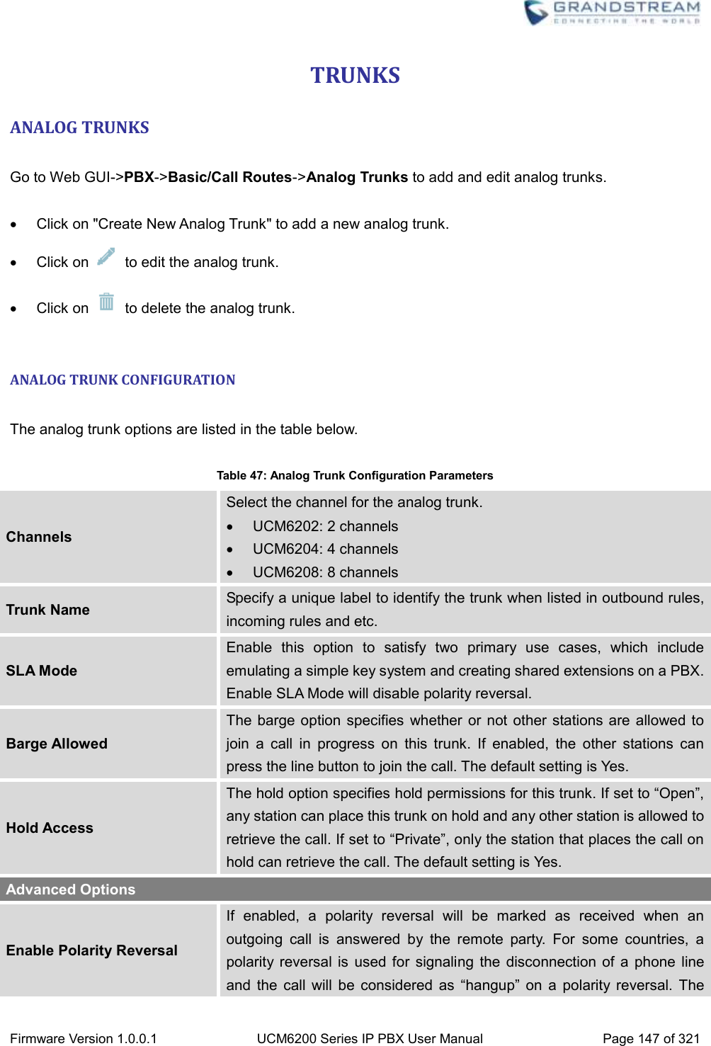
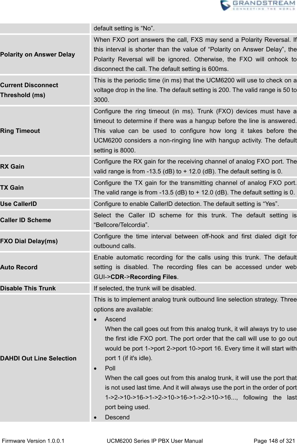
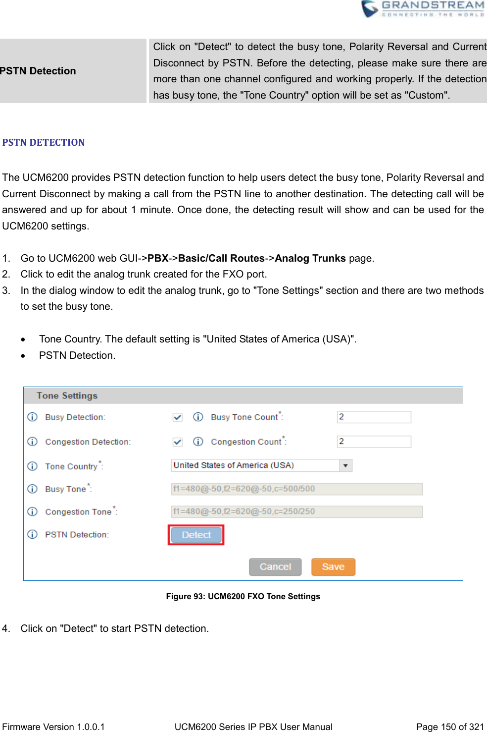
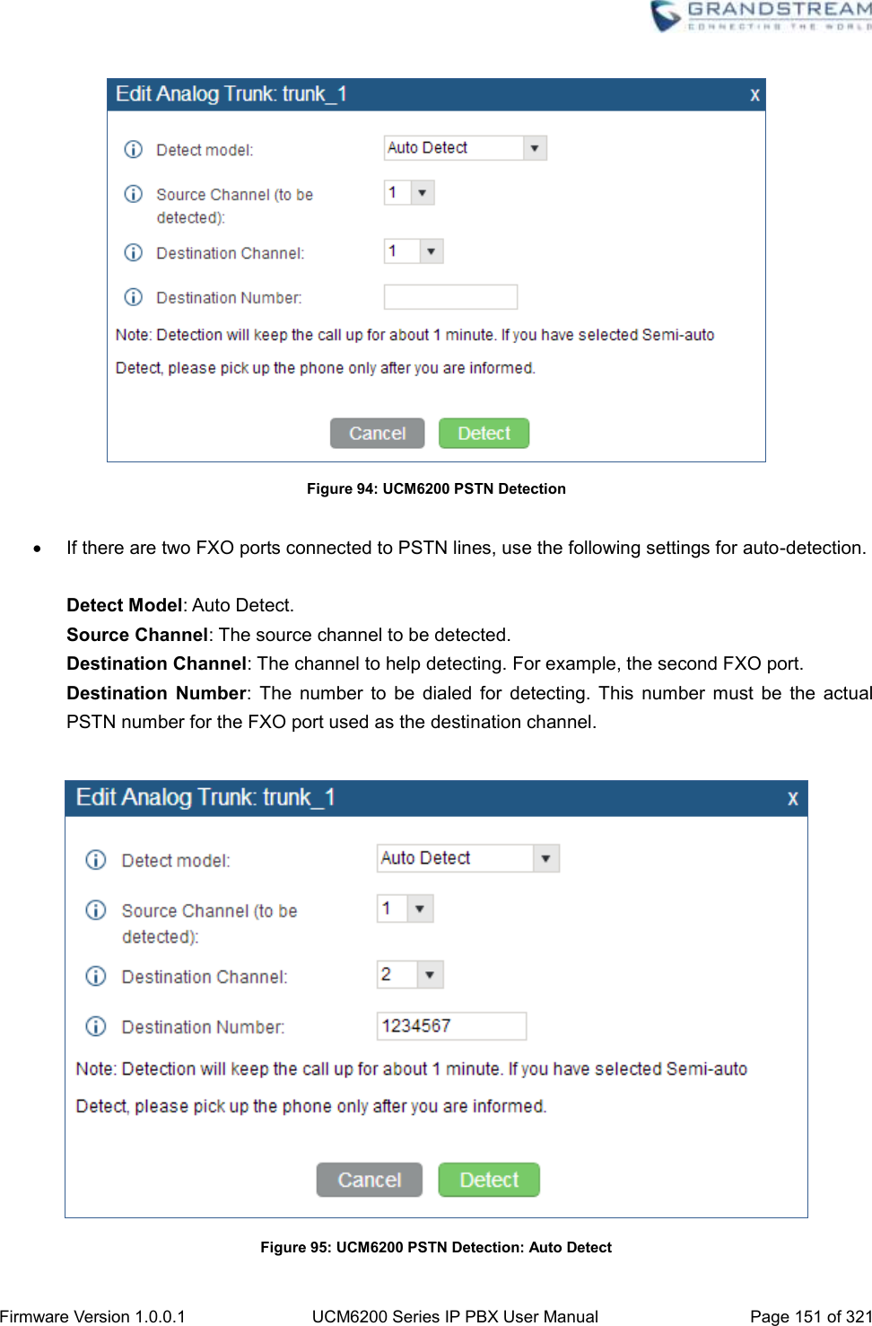
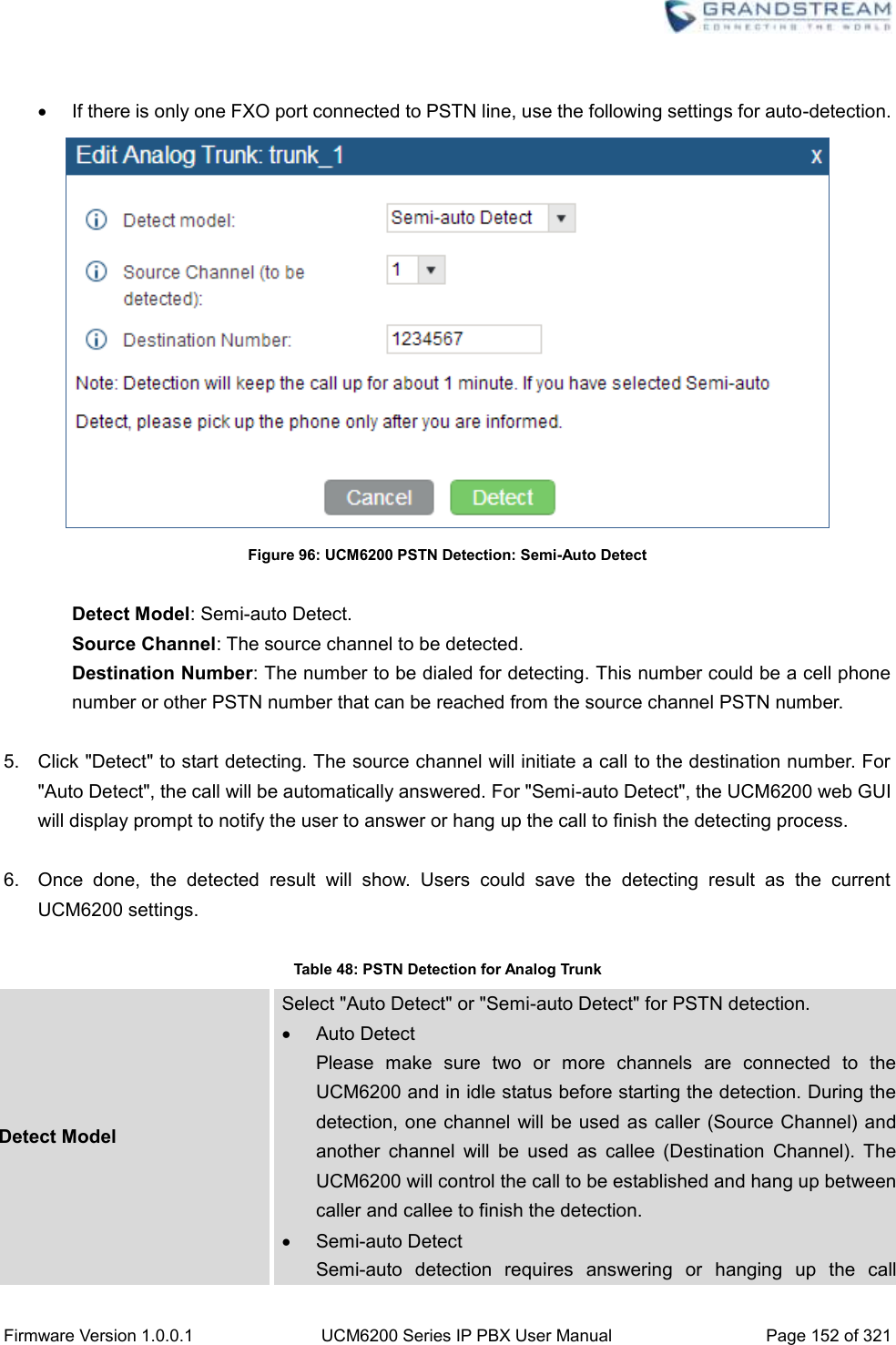
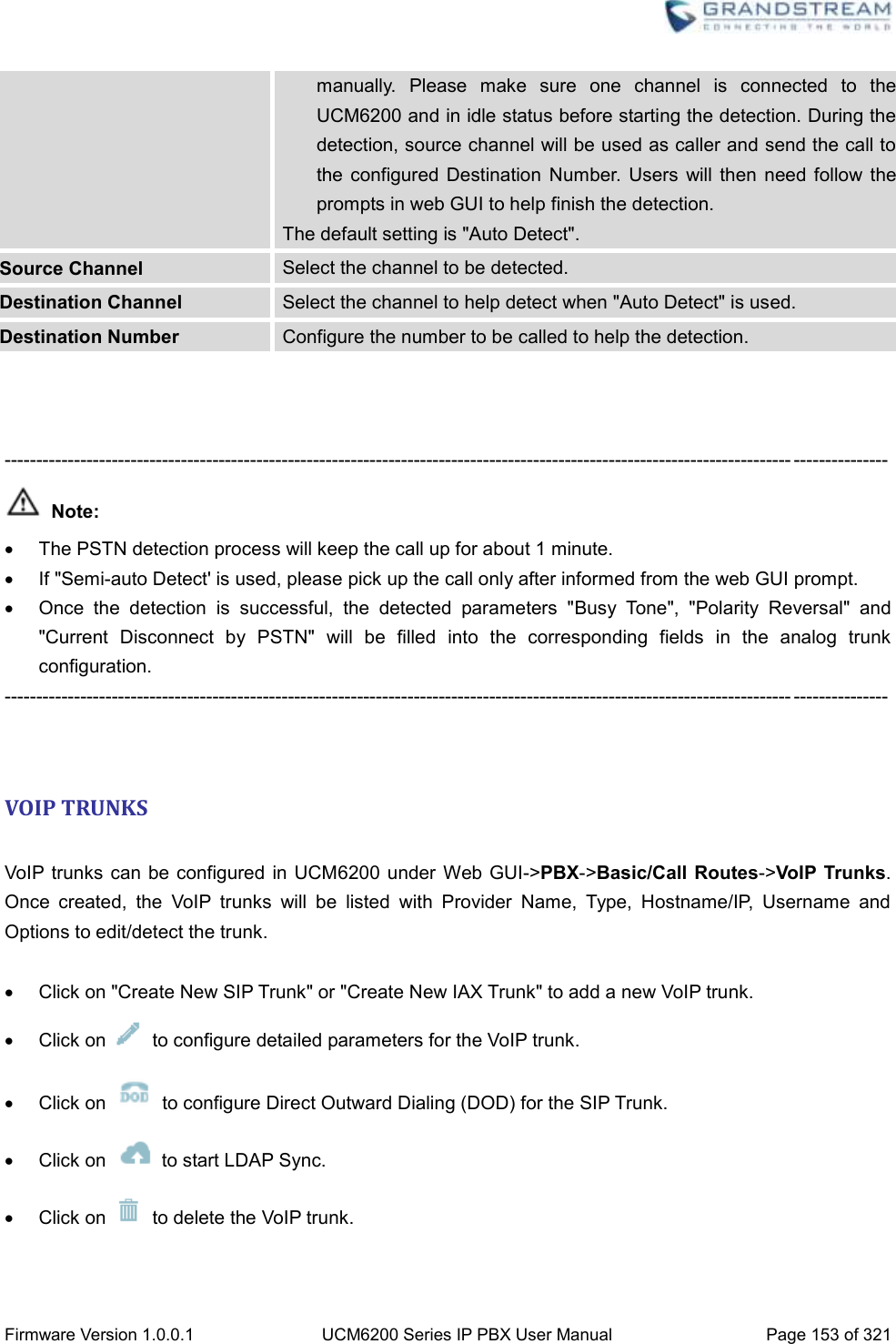
![Firmware Version 1.0.0.1 UCM6200 Series IP PBX User Manual Page 149 of 321 When the call goes out from this analog trunk, it will always try to use the last idle FXO port. The port order that the call will use to go out would be port 16->port 10->port 2->port 1. Every time it will start with port 16 (if it's idle). The default setting is “Ascend” mode. Tone Settings Busy Detection Busy Detection is used to detect far end hangup or for detecting busy signal. The default setting is "Yes". Busy Tone Count If "Busy Detection" is enabled, users can specify the number of busy tones to be played before hanging up. The default setting is 2. Better results might be achieved if set to 4, 6 or even 8. Please note that the higher the number is, the more time is needed to hangup the channel. However, this might lower the probability to get random hangup. Congestion Detection Congestion detection is used to detect far end congestion signal. The default setting is "Yes". Congestion Count If "Congestion Detection" is enabled, users can specify the number of congestion tones to wait for. The default setting is 2. Tone Country Select the country for tone settings. If "Custom" is selected, users could manually configure the values for Busy Tone and Congestion Tone. The default setting is "United States of America (USA)". Busy Tone Syntax: f1=val[@level][,f2=val[@level]],c=on1/off1[-on2/off2[-on3/off3]]; Frequencies are in Hz and cadence on and off are in ms. Frequencies Range: [0, 4000) Busy Level Range: (-300, 0) Cadence Range: [0, 16383]. Select Tone Country "Custom" to manually configure Busy Tone value. Default value: f1=480@-50,f2=620@-50,c=500/500 Congestion Tone Syntax: f1=val[@level][,f2=val[@level]],c=on1/off1[-on2/off2[-on3/off3]]; Frequencies are in Hz and cadence on and off are in ms. Frequencies Range: [0, 4000) Busy Level Range: (-300, 0) Cadence Range: [0, 16383]. Select Tone Country "Custom" to manually configure Busy Tone value. Default value: f1=480@-50,f2=620@-50,c=250/250](https://usermanual.wiki/Grandstream-Networks/UCM6202/User-Guide-3010507-Page-150.png)

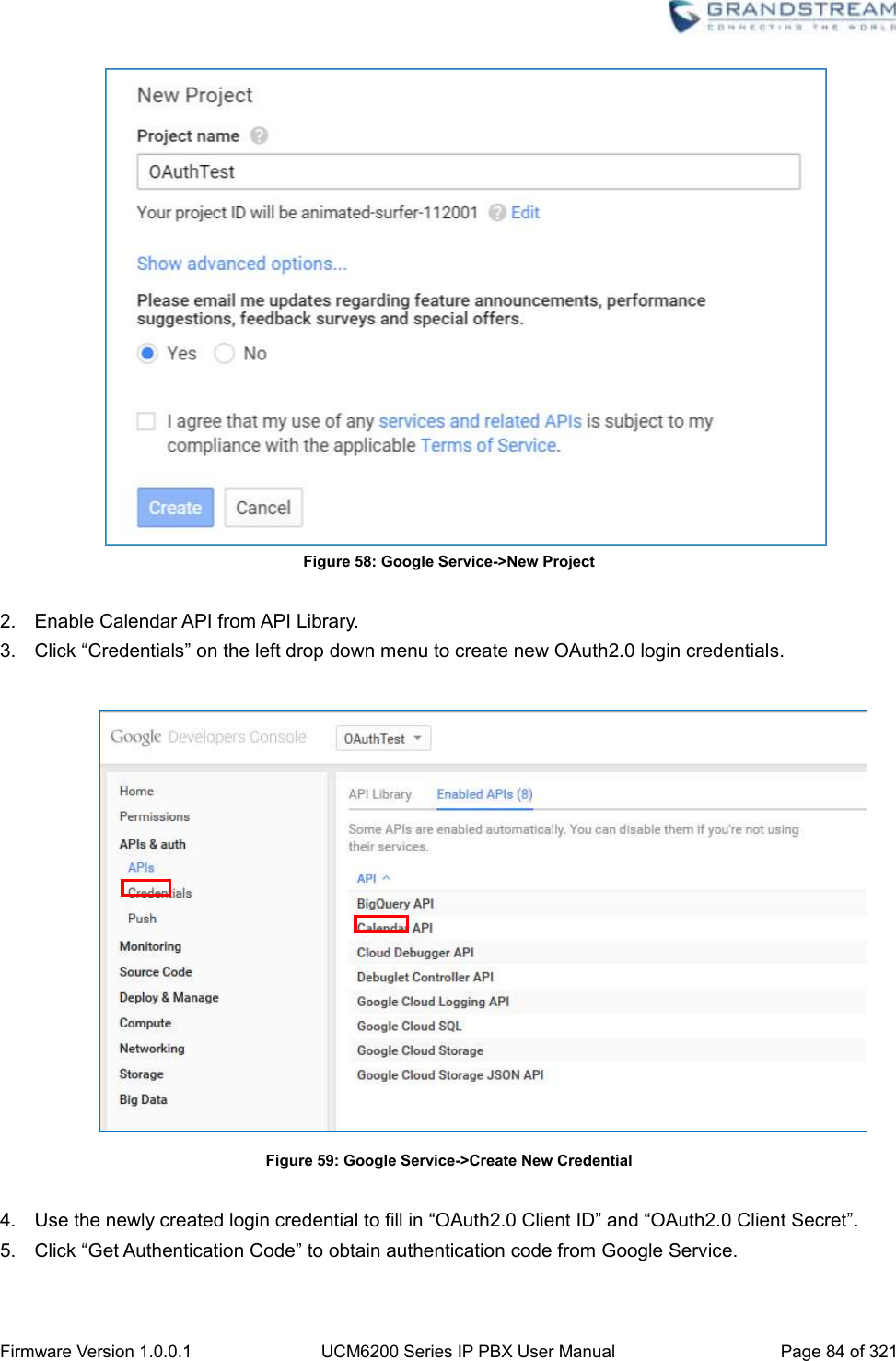
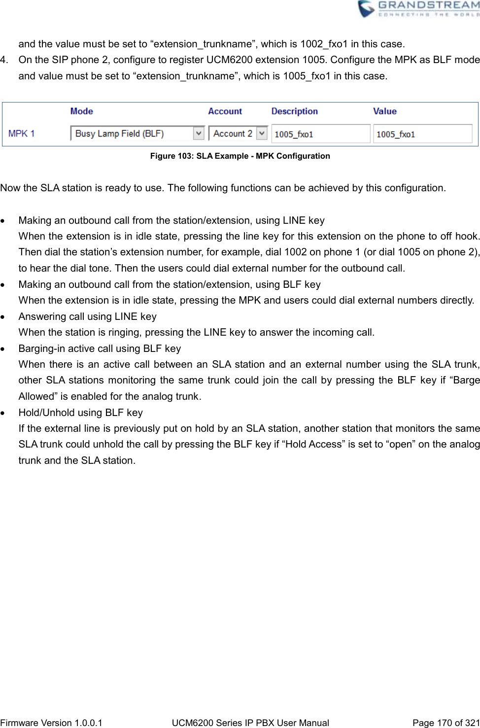
![Firmware Version 1.0.0.1 UCM6200 Series IP PBX User Manual Page 169 of 321 Figure 100: Enable SLA Mode for Analog Trunk Click on “Save”. The analog trunk will be listed with trunk mode “SLA”. Figure 101: Analog Trunk with SLA Mode Enabled 2. On the UCM6200, go to web UI->Basic/Call Routes->SLA Station page, click on “Create New SLA Station”. Please refer to section [CREATE/EDIT SLA STATION] for the configuration parameters. Users can create one or more SLA stations to monitor the analog trunk. The following figure shows two stations, 1002 and 1005, are configured to be associated with SLA trunk “fxo1”. Figure 102: SLA Example - SLA Station 3. On the SIP phone 1, configure to register UCM6200 extension 1002. Configure the MPK as BLF mode](https://usermanual.wiki/Grandstream-Networks/UCM6202/User-Guide-3010507-Page-170.png)
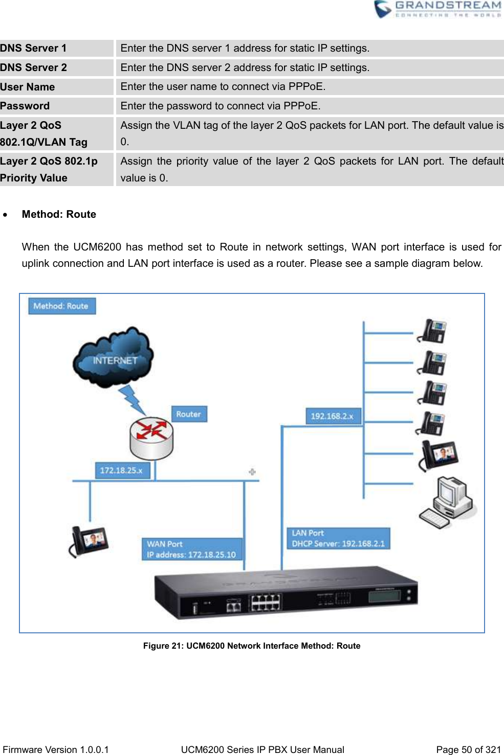
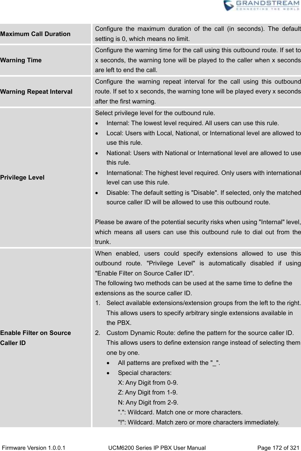
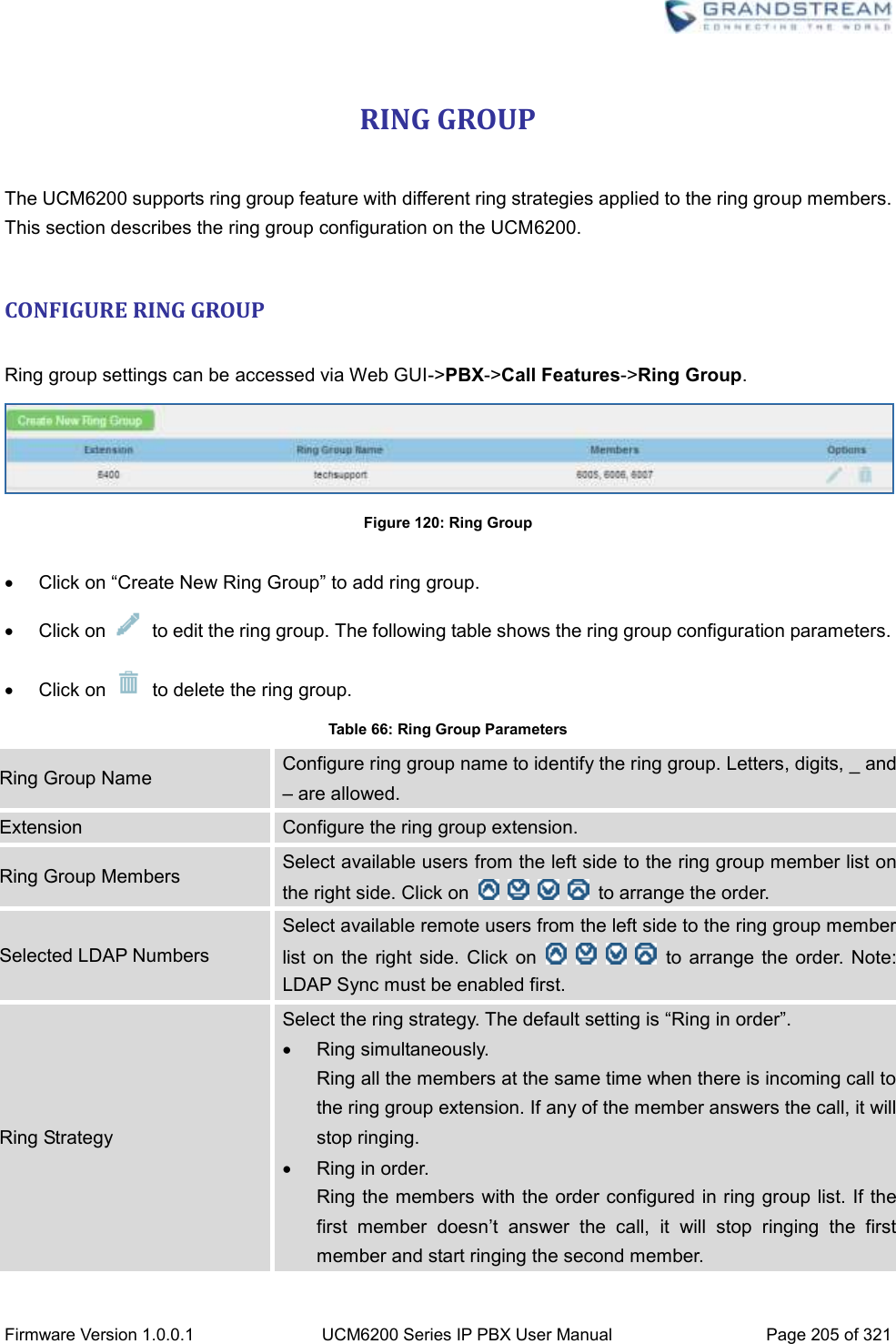
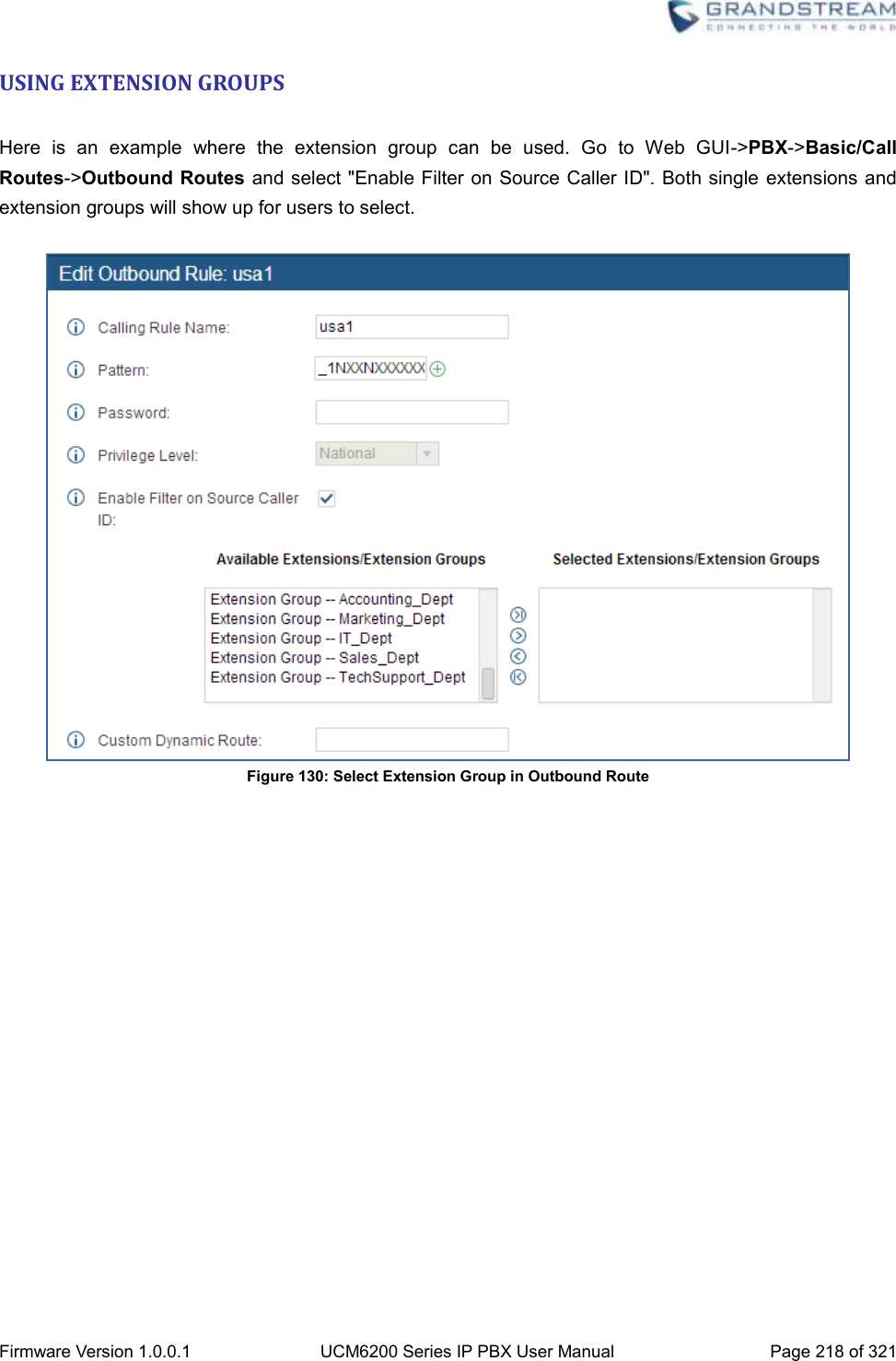
![Firmware Version 1.0.0.1 UCM6200 Series IP PBX User Manual Page 171 of 321 CALL ROUTES OUTBOUND ROUTES In the UCM6200, an outgoing calling rule pairs an extension pattern with a trunk used to dial the pattern. This allows different patterns to be dialed through different trunks (e.g., "Local" 7-digit dials through a FXO while "Long distance" 10-digit dials through a low-cost SIP trunk). Users can also set up a failover trunk to be used when the primary trunk fails. Go to Web GUI->PBX->Basic/Call Routes->Outbound Routes to add and edit outbound rules. Click on "Create New Outbound Rule" to add a new outbound route. Click on to edit the outbound route. Click on to delete the outbound route. On the UCM6200, the outbound route priority is based on “Best matching pattern”. For example, the UCM6200 has outbound route A with pattern 1xxx and outbound route B with pattern 10xx configured. When dialing 1000 for outbound call, outbound route B will always be used first. This is because pattern 10xx is a better match than pattern 1xxx. Only when there are multiple outbound routes with the same pattern configured, users can click on to move the outbound route up/down to arrange the priority among those outbound routes. Table 56: Outbound Route Configuration Parameters Calling Rule Name Configure the name of the calling rule (e.g., local, long_distance, and etc). Letters, digits, _ and - are allowed. Pattern All patterns are prefixed with the "_". Special characters: X: Any Digit from 0-9. Z: Any Digit from 1-9. N: Any Digit from 2-9. ".": Wildcard. Match one or more characters. "!": Wildcard. Match zero or more characters immediately. Example: [12345-9] - Any digit from 1 to 9. Password Configure the password for users to use this rule when making outbound calls. Call Duration Limit Enable to configure the maximum duration for the call using this outbound route.](https://usermanual.wiki/Grandstream-Networks/UCM6202/User-Guide-3010507-Page-172.png)
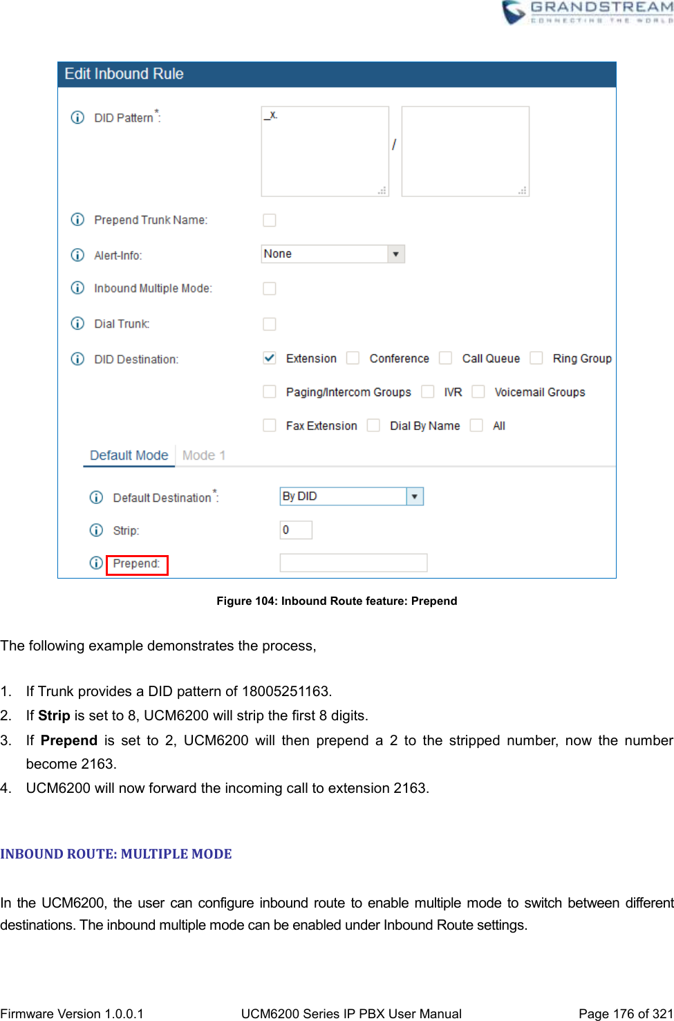
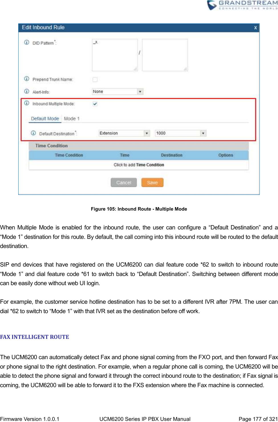
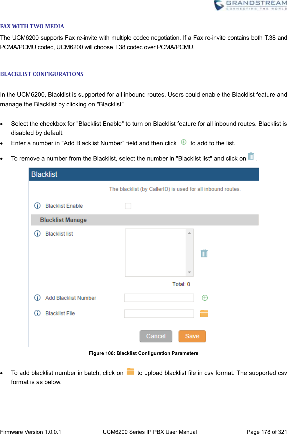
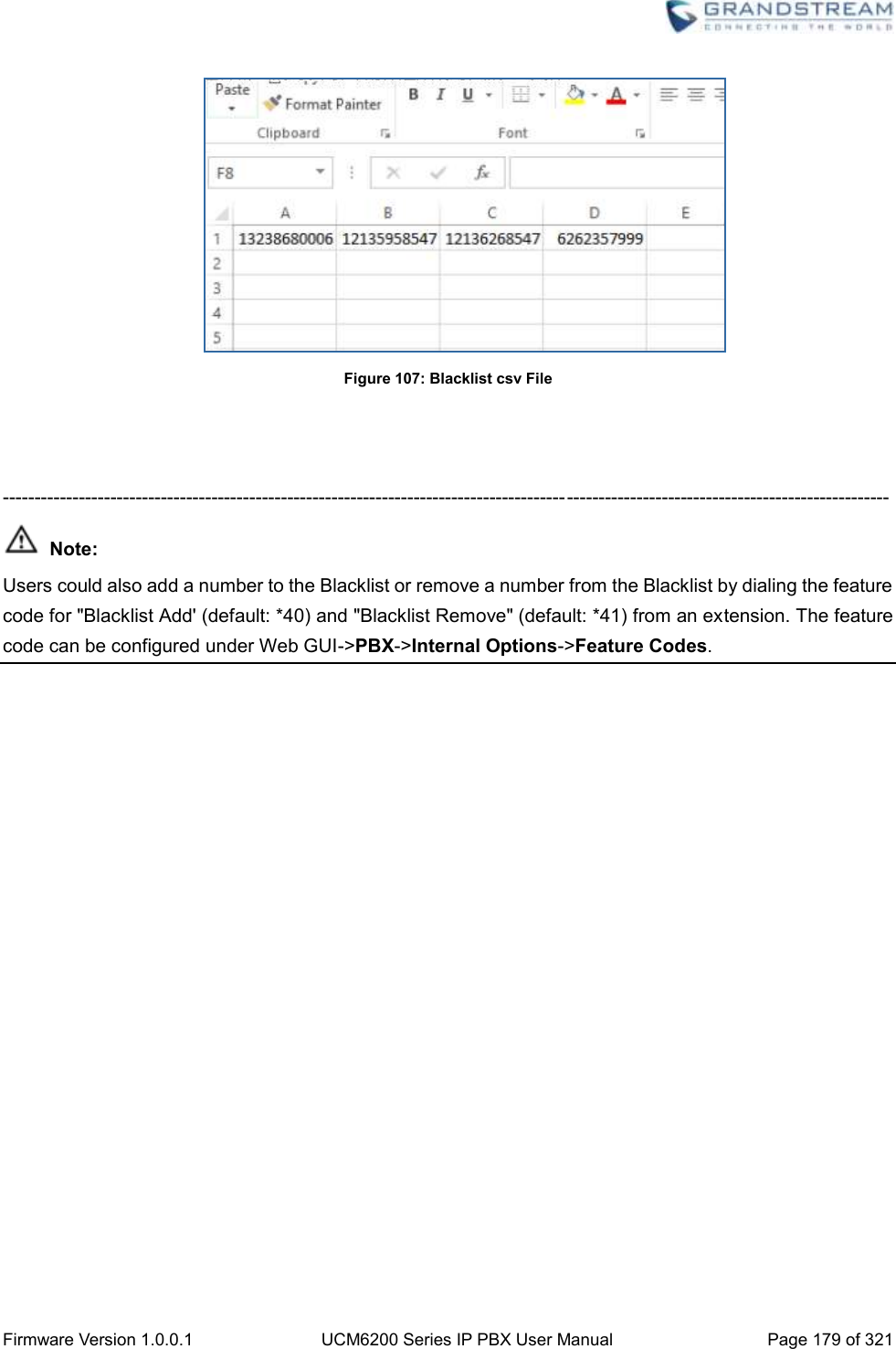
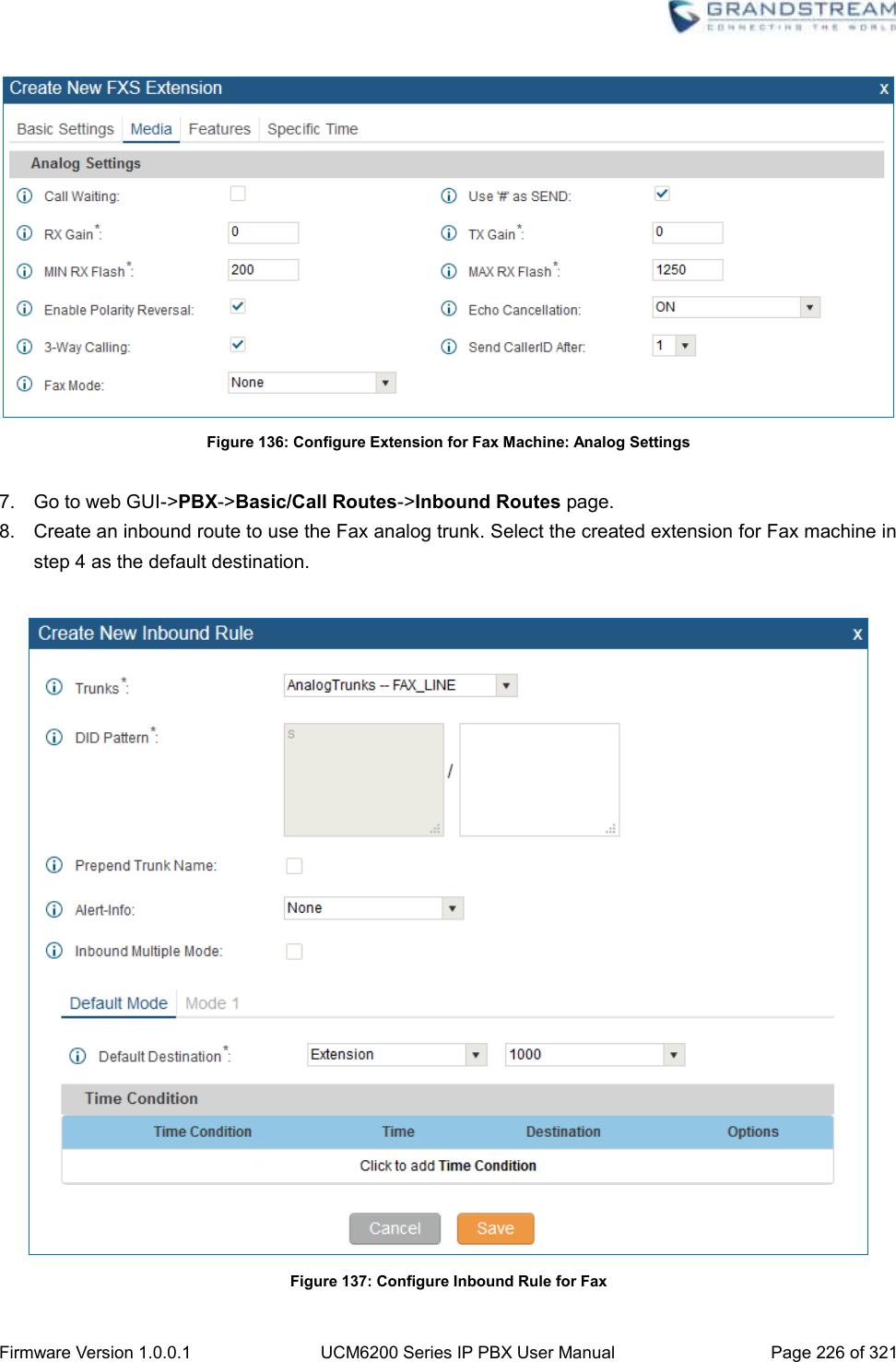
![Firmware Version 1.0.0.1 UCM6200 Series IP PBX User Manual Page 173 of 321 Example: [12345-9] - Any digit from 1 to 9. Send This Call Through Trunk Use Trunk Select the trunk for this outbound rule. Strip Allows the user to specify the number of digits that will be stripped from the beginning of the dialed string before the call is placed via the selected trunk. Example: The users will dial 9 as the first digit of a long distance calls. However, 9 should not be sent out via analog lines and the PSTN line. In this case, 1 digit should be stripped before the call is placed. Prepend Specify the digits to be prepended before the call is placed via the trunk. Those digits will be prepended after the dialing number is stripped. Use Failover Trunk Failover Trunk Failover trunks can be used to make sure that a call goes through an alternate route, when the primary trunk is busy or down. If "Use Failover Trunk" is enabled and "Failover trunk" is defined, the calls that cannot be placed via the regular trunk may have a secondary trunk to go through. Example: The user's primary trunk is a VoIP trunk and the user would like to use the PSTN when the VoIP trunk is not available. The PSTN trunk can be configured as the failover trunk of the VoIP trunk. Strip Allows the user to specify the number of digits that will be stripped from the beginning of the dialed string before the call is placed via the selected trunk. Example: The users will dial 9 as the first digit of a long distance calls. However, 9 should not be sent out via analog lines and the PSTN line. In this case, 1 digit should be stripped before the call is placed. Prepend Specify the digits to be prepended before the call is placed via the trunk. Those digits will be prepended after the dialing number is stripped. INBOUND ROUTES Inbound routes can be configured via Web GUI->PBX->Basic/Call Routes->Inbound Routes. Click on "Create New Inbound Rule" to add a new inbound route. Click on "Blacklist" to configure blacklist for all inbound routes. Click on to edit the inbound route.](https://usermanual.wiki/Grandstream-Networks/UCM6202/User-Guide-3010507-Page-174.png)
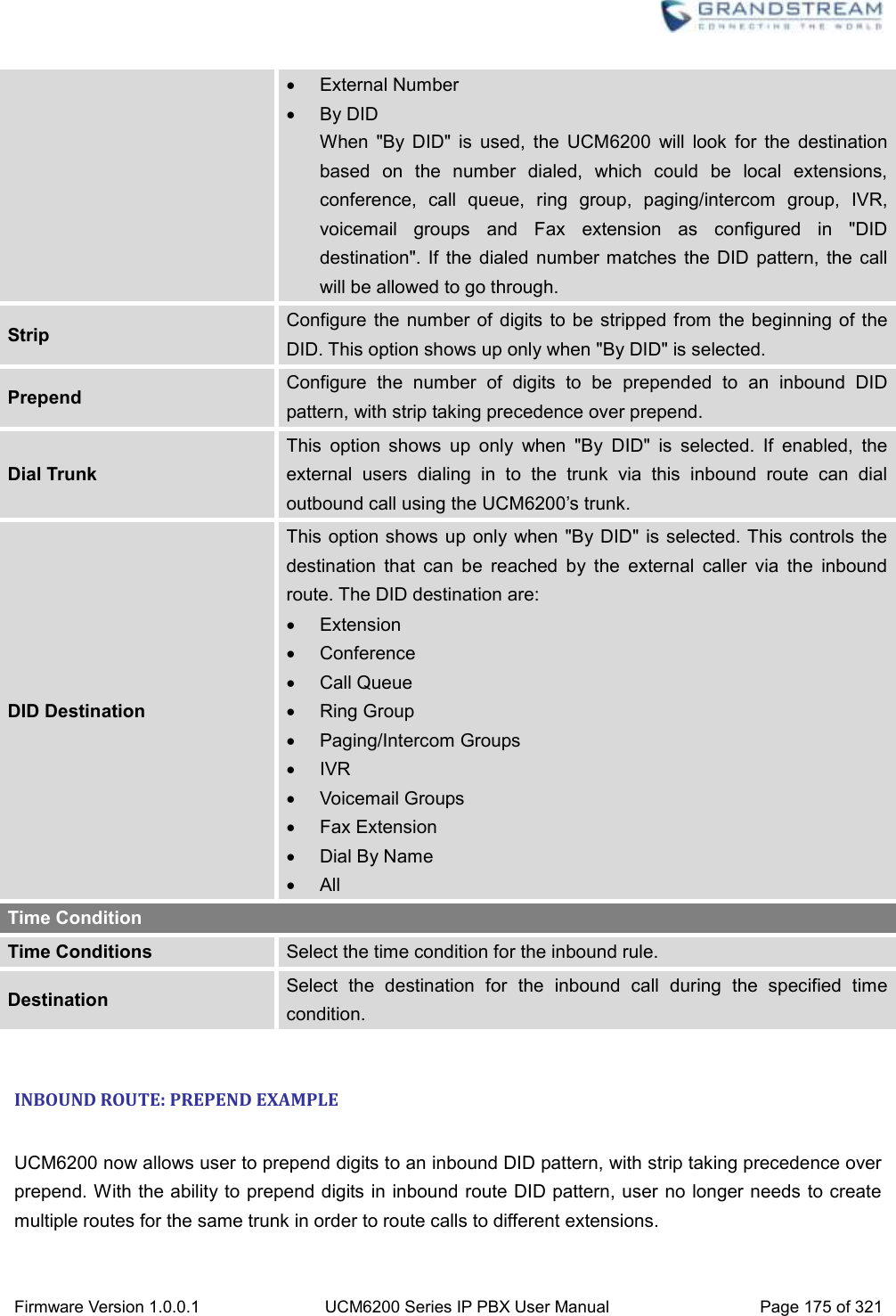
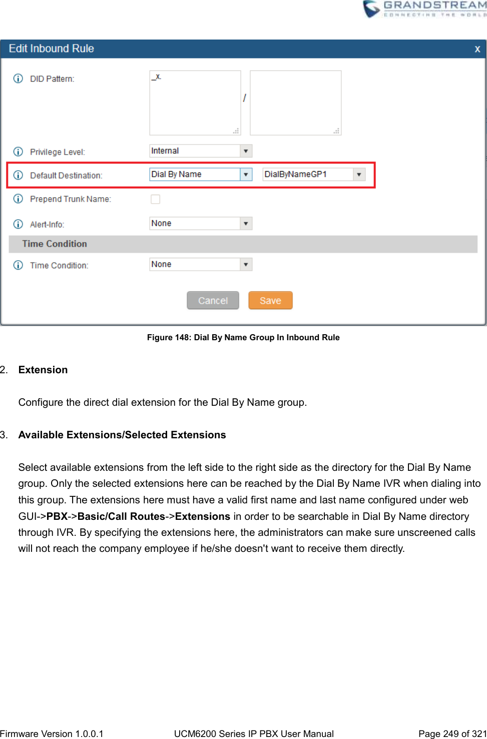
![Firmware Version 1.0.0.1 UCM6200 Series IP PBX User Manual Page 174 of 321 Click on to delete the inbound route. INBOUND RULE CONFIGURATIONS Table 57: Inbound Rule Configuration Parameters Trunks Select the trunk to configure the inbound rule. DID Pattern All patterns are prefixed with the "_". Special characters: X: Any Digit from 0-9. Z: Any Digit from 1-9. N: Any Digit from 2-9. ".": Wildcard. Match one or more characters. "!": Wildcard. Match zero or more characters immediately. Example: [12345-9] - Any digit from 1 to 9. The pattern can be composed of two parts, divided by a ‘/’ character. The first part is used to specify the dialed number the second part is used to specify the caller ID and it is optional, if set it means only the extension with the specific caller ID is allowed to call in or call out. For example, patter '_2XXX/1234' means the only extension with the caller ID '1234' is allowed to use this rule. Prepend Trunk Name Prepend trunk name to display Alert-Info Configure the Alert-Info, when UCM6200 receives an INVITE request, the Alert-Info header field specifies an alternative ring tone to the UAS. Inbound Multiple Mode Multiple mode allows user to switch between destinations of the inbound rule by feature codes. Configure related feature codes in the “Feature Codes” page. If this option is enabled, user can use feature code to switch between different destinations. Default Destination Select the default destination for the inbound call. Extension Voicemail Conference Room Queue Ring Group Paging/Intercom Voicemail Group Fax DISA IVR Dial By Name](https://usermanual.wiki/Grandstream-Networks/UCM6202/User-Guide-3010507-Page-175.png)

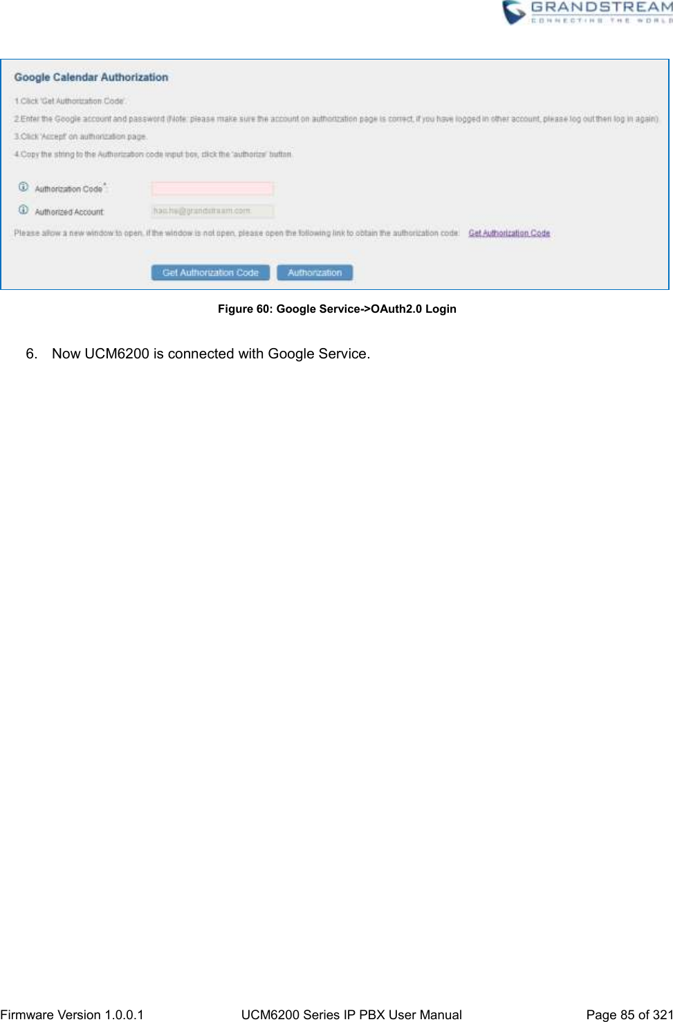
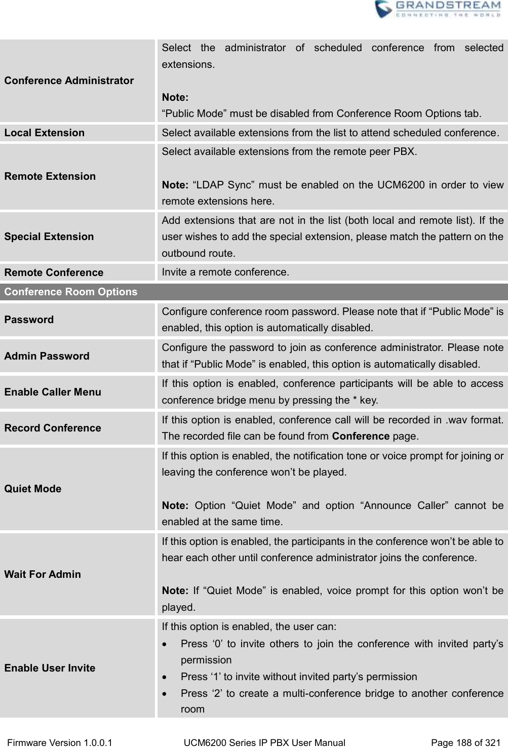
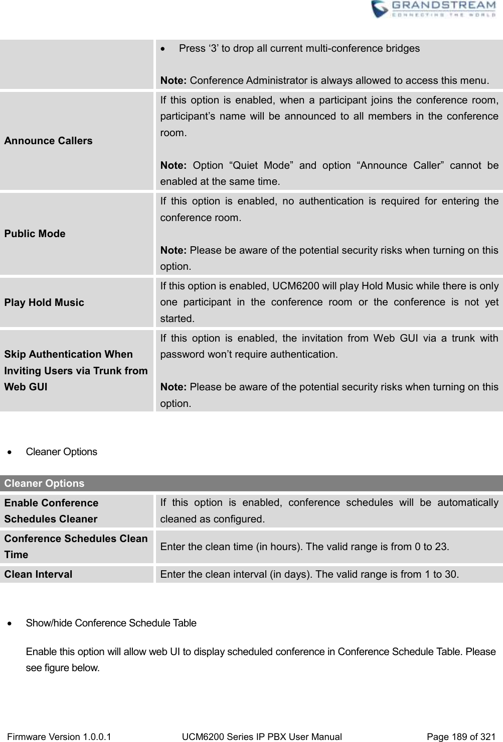
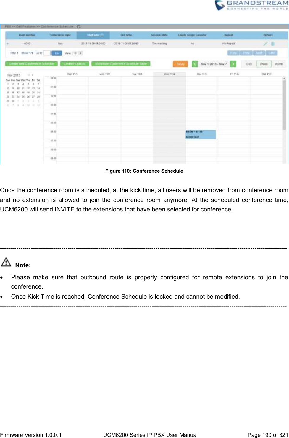
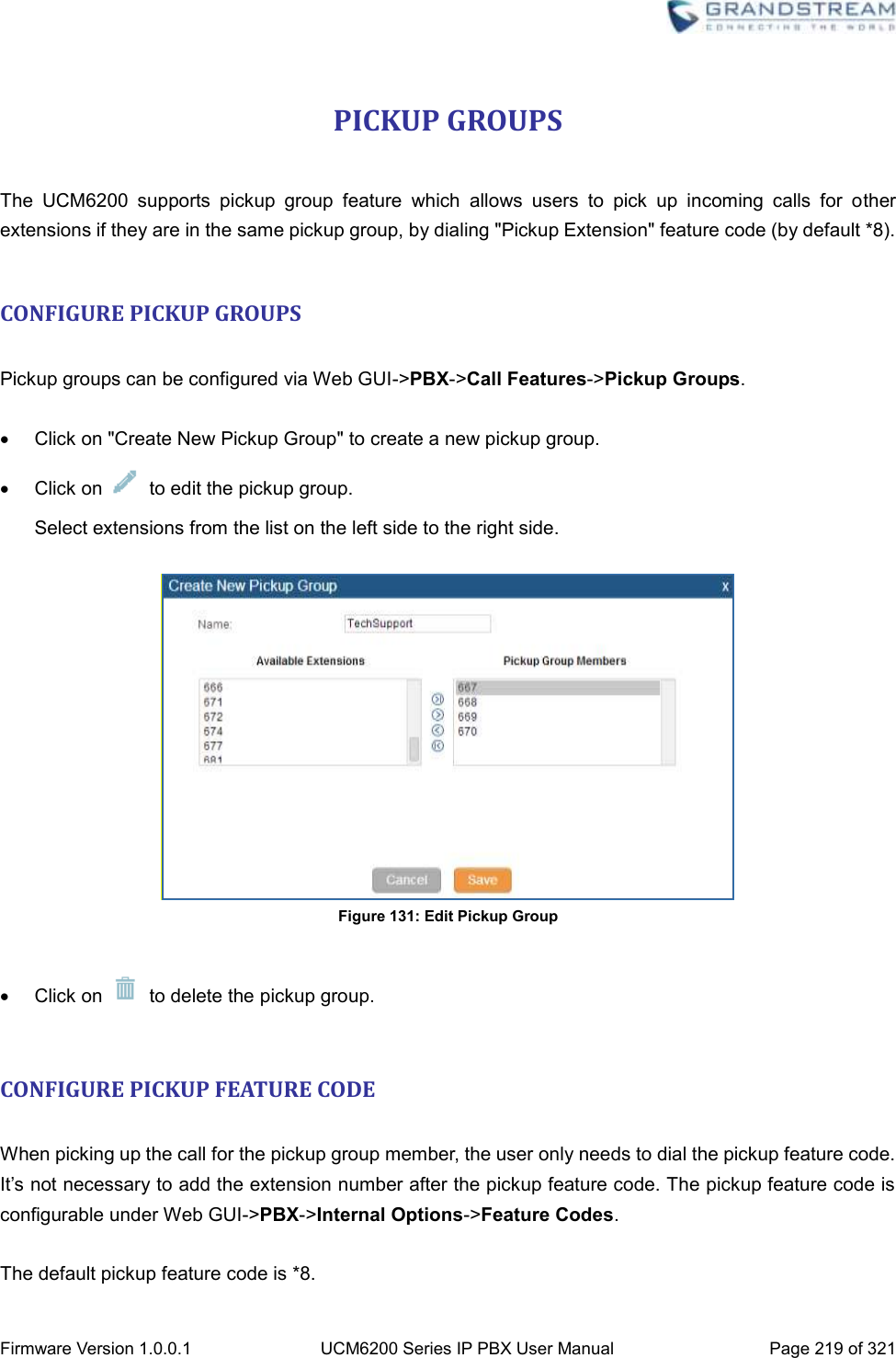
![Firmware Version 1.0.0.1 UCM6200 Series IP PBX User Manual Page 187 of 321 CONFERENCE SCHEDULE CONFERENCE SCHEUDLE CONFIGURATION Conference Schedule can be found under UCM6200 web UI->PBX->Call Features->Conference Schedule. Users can create, edit, view and delete a Conference Schedule. Click on “Create New Conference Schedule” to add a new Conference Schedule. Click on the scheduled conference to edit or delete the event. After the user configures UCM6200 with Google Service Settings [GOOGLE SERVICE SETTINGS SUPPORT] and enables Google Calendar for Conference Schedule, the conference schedule on the UCM6200 can be synchronized with Google Calendar for authorized Google account. Table 60: Conference Schedule Parameters Schedule Options Conference Topic Configure the name of the scheduled conference. Letters, digits, _ and - are allowed. Conference Room Select a conference room for this scheduled conference. Kick Time(m) Set kick time before conference starts. When kick time is reached, a warning prompt will be played for all attendees in the conference room. After 5 minutes, this conference room will be cleared and locked for the scheduled conference to begin. Note: Kick Time cannot be less than 6 minutes in order to clear the conference room. Description The description of scheduled conference. Repeat Repeat interval of scheduled conference. By default it’s set to single event. Schedule Time Configure the beginning date and duration of scheduled conference. Note: Please pay attention to avoid time conflict on schedules in the same conference room. Enable Google Calendar Select this option to sync scheduled conference with Google Calendar. Note: Google Service Setting OAuth2.0 must be configured on the UCM6200. Please refer to section [GOOGLE SERVICE SETTINGS SUPPORT].](https://usermanual.wiki/Grandstream-Networks/UCM6202/User-Guide-3010507-Page-188.png)


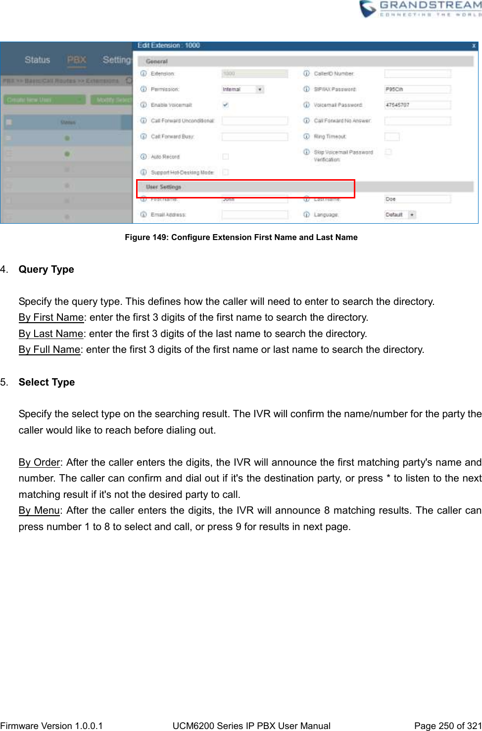
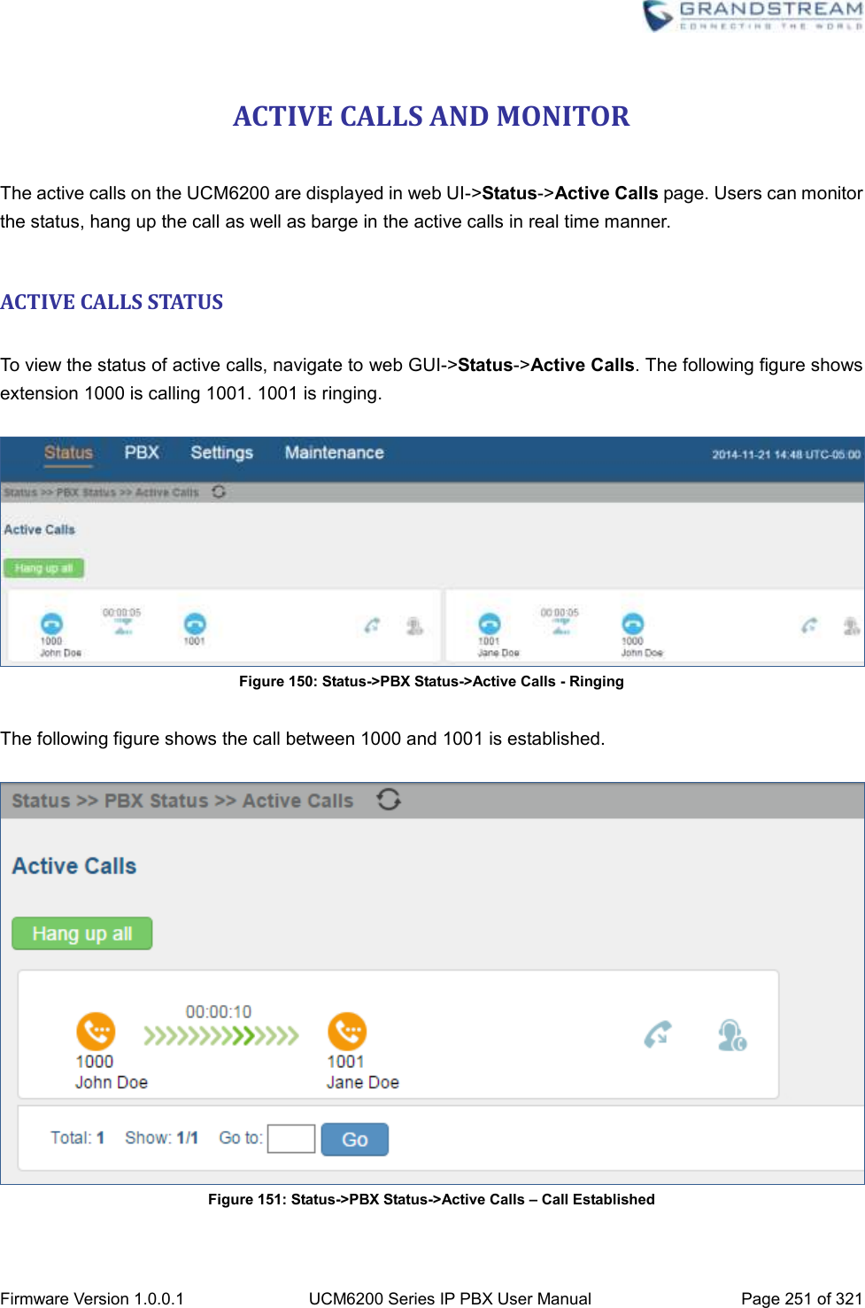
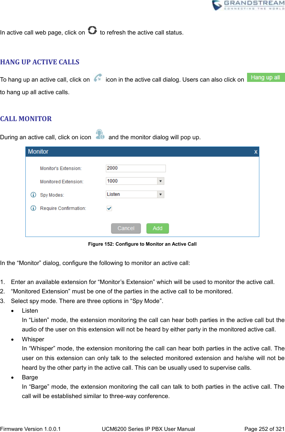
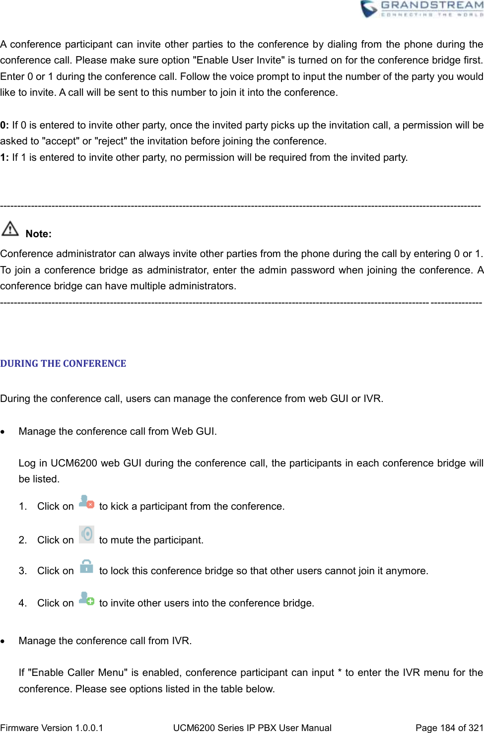
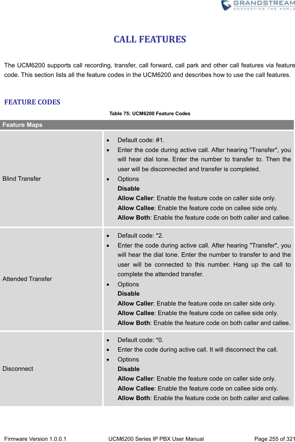
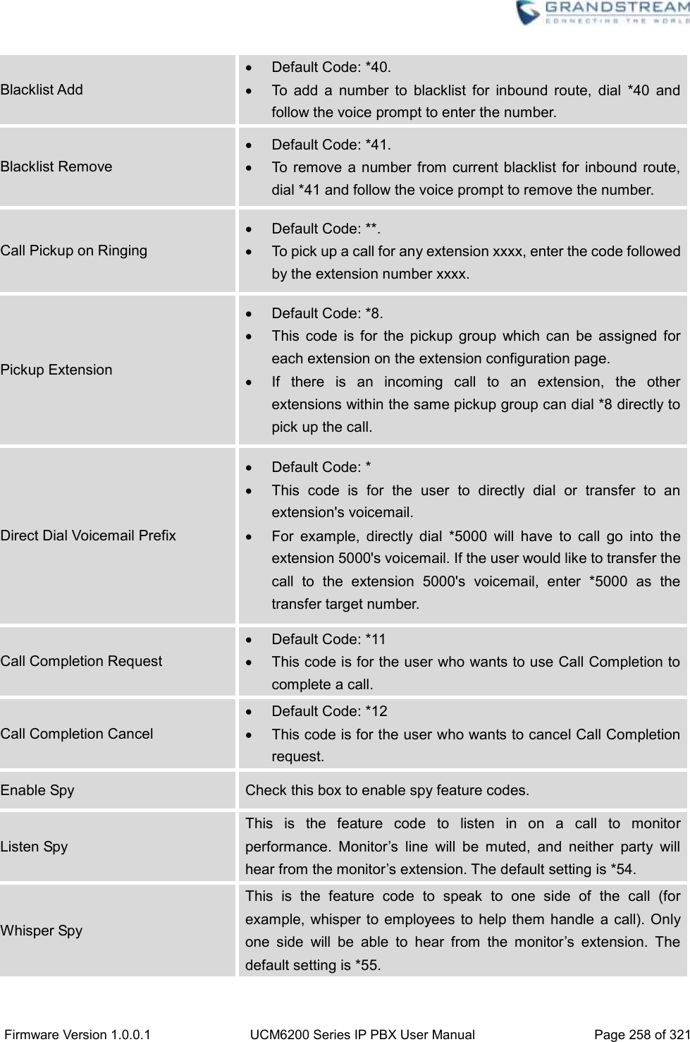
![Firmware Version 1.0.0.1 UCM6200 Series IP PBX User Manual Page 253 of 321 4. Enable or disable “Require Confirmation” option. If enabled, the confirmation of the invited monitor’s extension is required before the active call can be monitored. This option can be used to avoid adding participant who has auto-answer configured or call forwarded to voicemail. 5. Click on “Add”. An INVITE will be sent to the monitor’s extension. The monitor can answer the call and start monitoring. If “Require Confirmation” is enabled, the user will be asked to confirm to monitor the call. Another way to monitor active calls is to dial the corresponding feature codes from an extension. Please refer to [Table 75: UCM6200 Feature Codes] and [ENABLE SPY] section for instructions.](https://usermanual.wiki/Grandstream-Networks/UCM6202/User-Guide-3010507-Page-254.png)


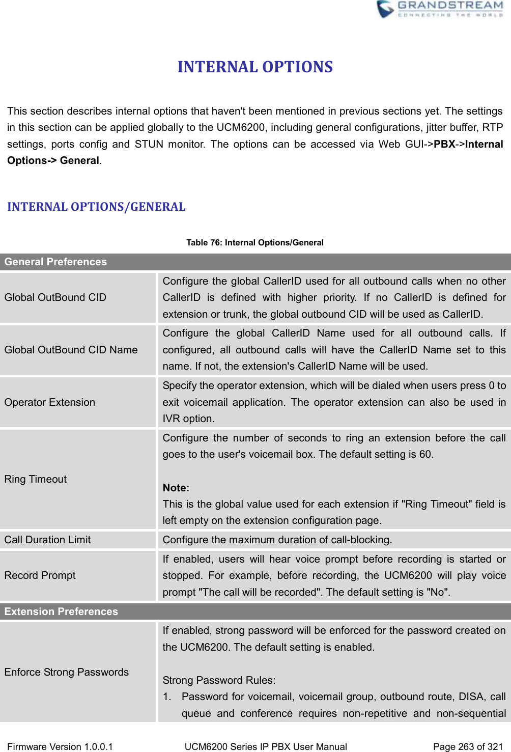
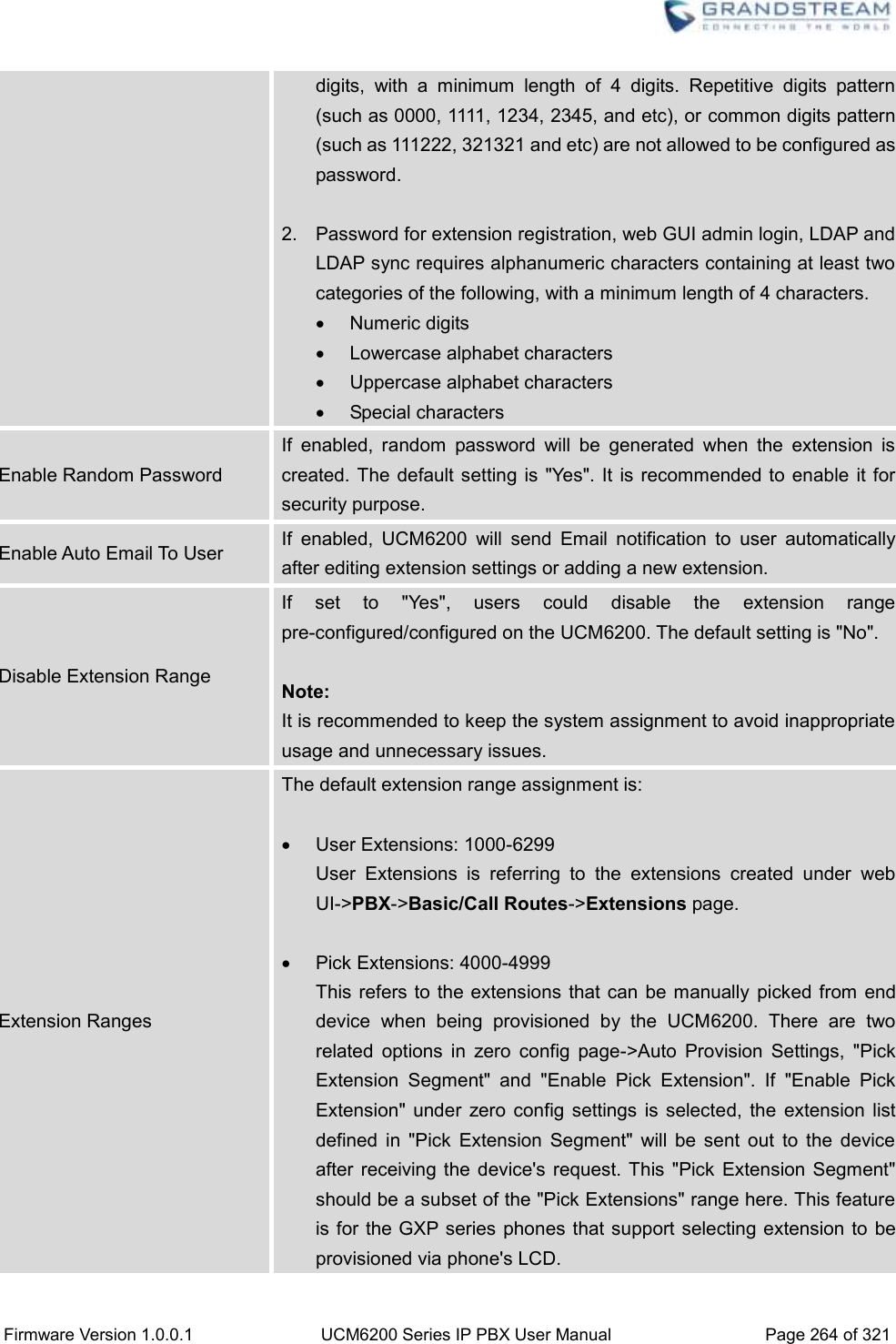
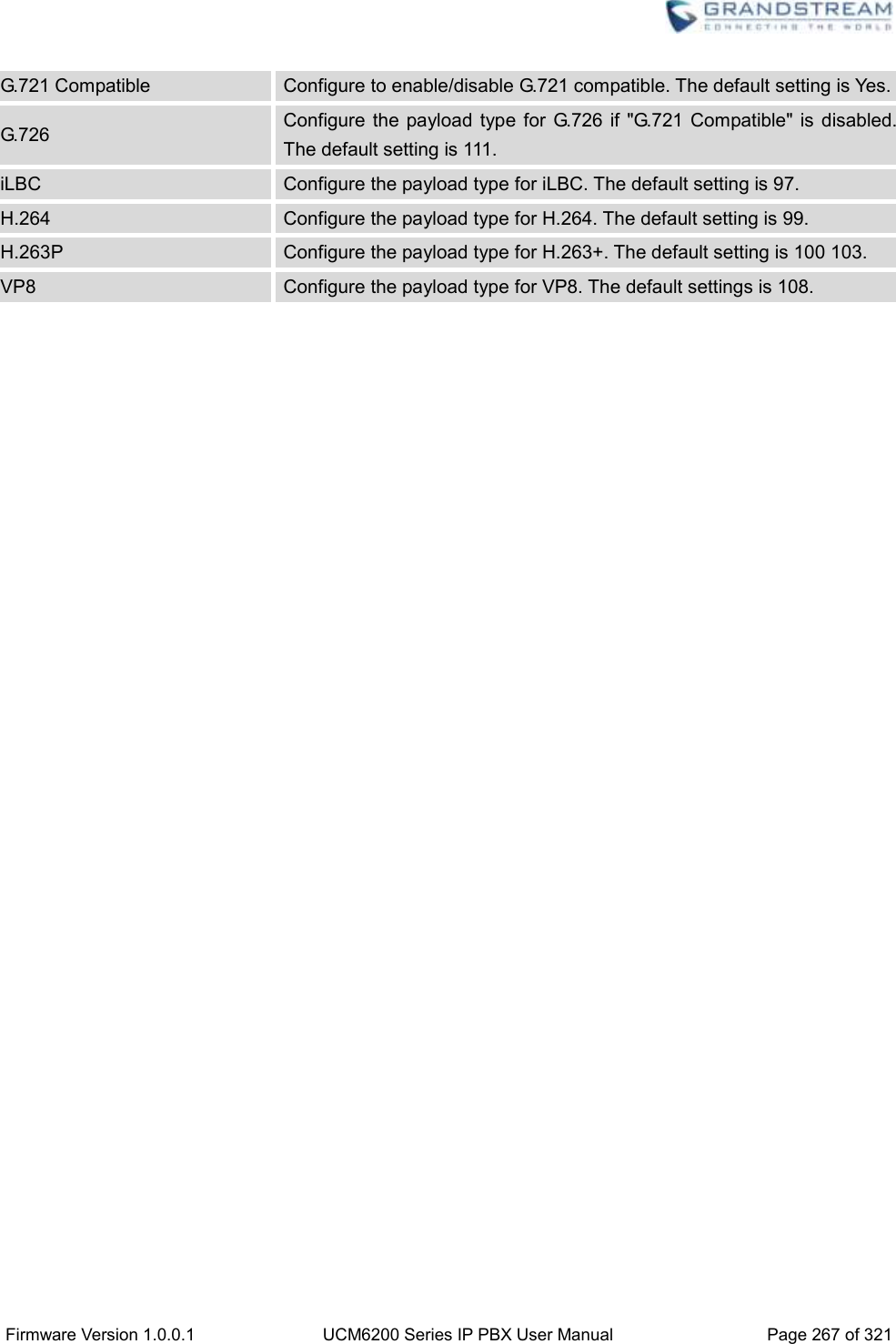
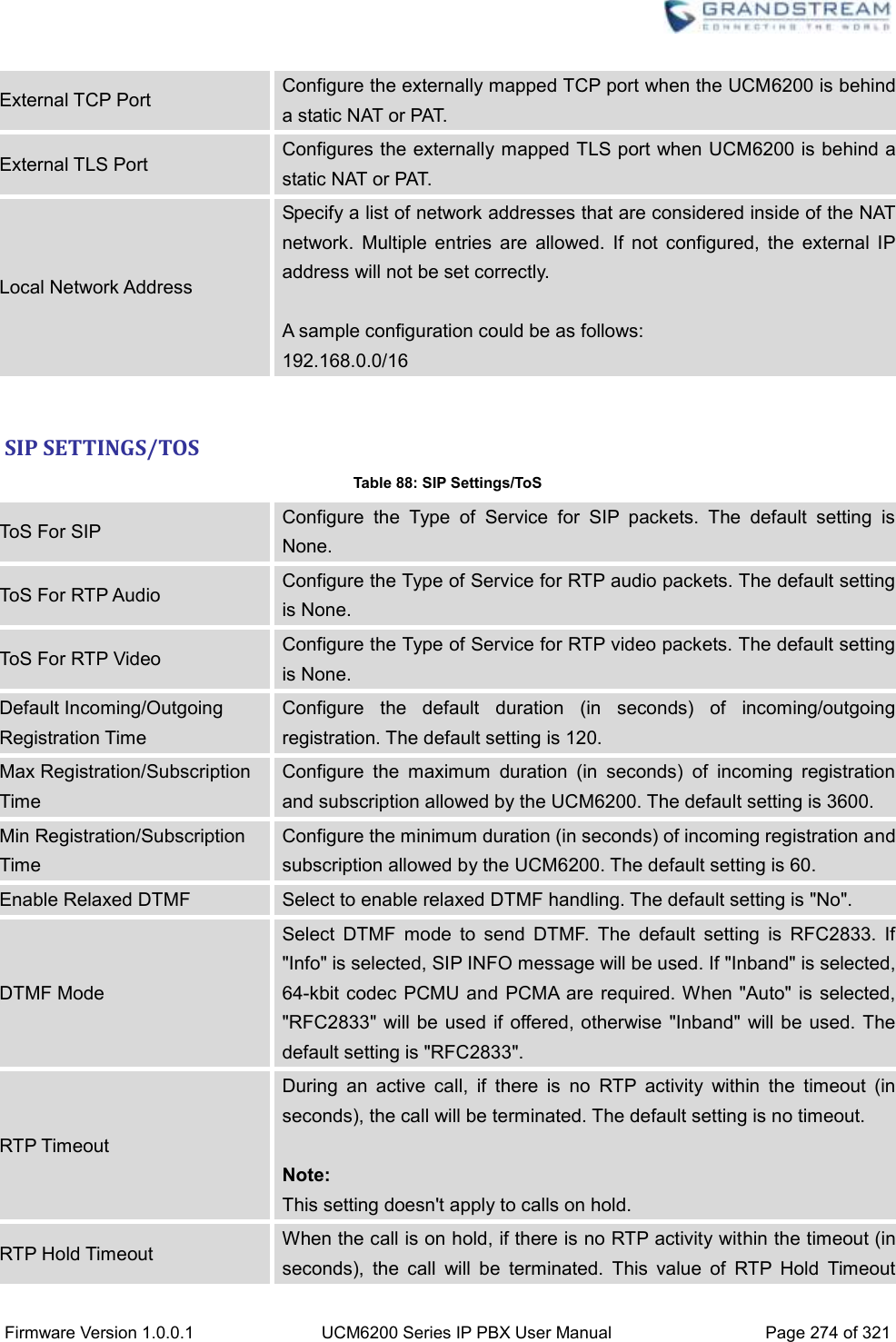
![Firmware Version 1.0.0.1 UCM6200 Series IP PBX User Manual Page 266 of 321 INTERNAL OPTIONS/RTP SETTINGS Table 78: Internal Options/RTP Settings RTP Start Configure the RTP port starting number. The default setting is 10000. RTP End Configure the RTP port ending address. The default setting is 20000. Strict RTP Configure to enable or disable strict RTP protection. If enabled, RTP packets that do not come from the source of the RTP stream will be dropped. The default setting is "Disable". RTP Checksums Configure to enable or disable RTP Checksums on RTP traffic. The default setting is "Disable". ICE Support Configure whether to support ICE. The default setting is enabled. ICE is the integrated use of STUN and TURN structure to provide reliable VoIP or video calls and media transmission, via a SIP request/ response model or multiple candidate endpoints exchanging IP addresses and ports, such as private addresses and TURN server address. STUN Server Configure STUN server address. STUN protocol is a Client/Server and also a Request/Response protocol. It’s used to check the connectivity between the two terminals, such as maintaining a NAT binding entries keep-alive agreement. The default STUN Server is stun.ipvideotalk.com. Valid format: [(hostname | IP-address) [':' port] The default port number is 3478 if not specified. INTERNAL OPTIONS/PAYLOAD The UCM6200 payload type for audio codecs and video codes can be configured here. Table 79: Internal Options/Payload AAL2-G.726 Configure payload type for ADPCM (G.726, 32kbps, AAL2 codeword packing). The default setting is 112. DTMF Configured payload type for DTMF. The default setting is 101.](https://usermanual.wiki/Grandstream-Networks/UCM6202/User-Guide-3010507-Page-267.png)

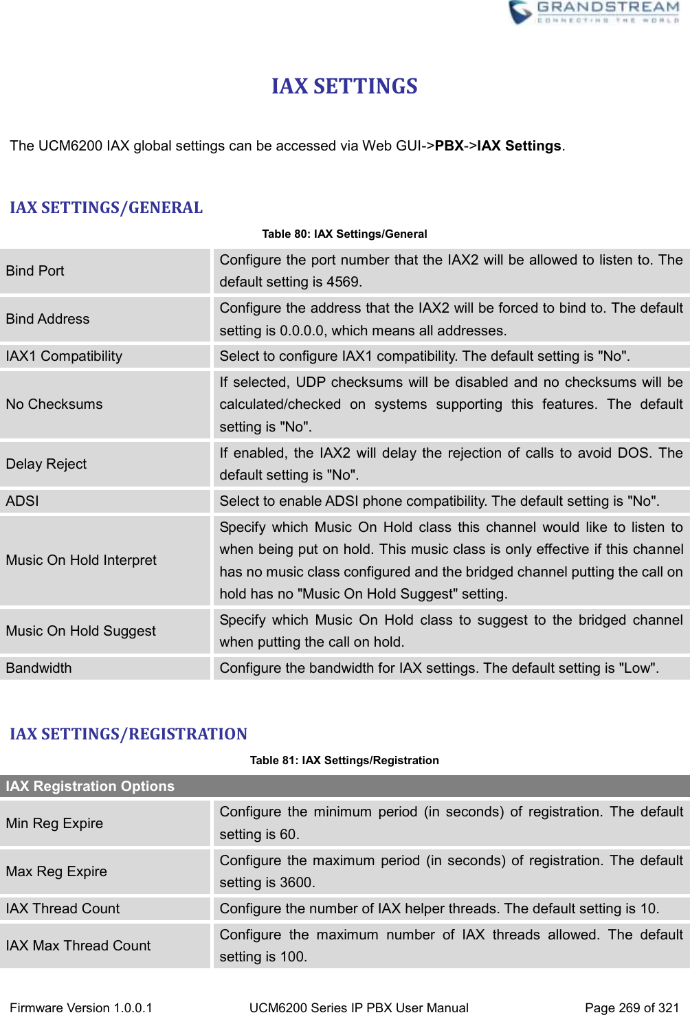
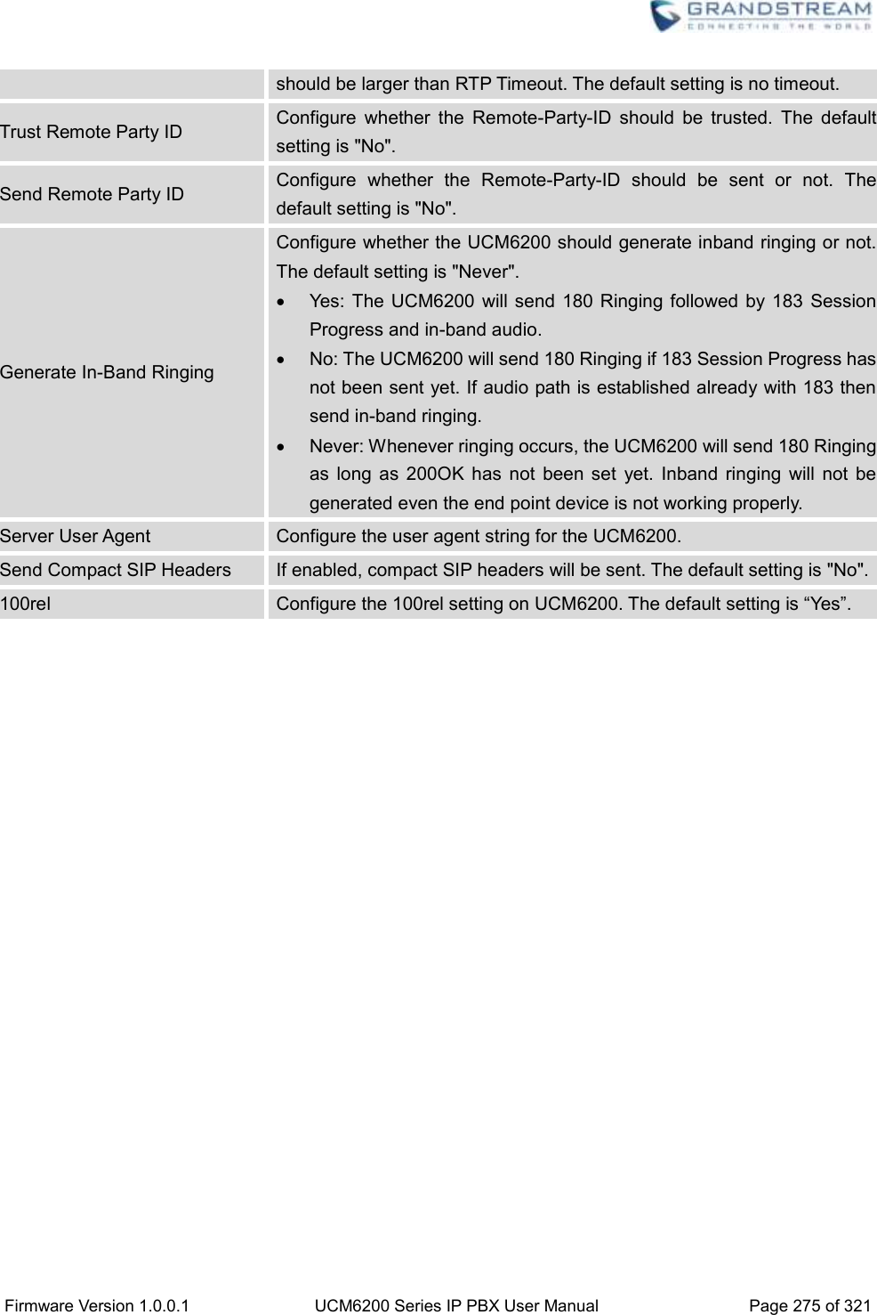

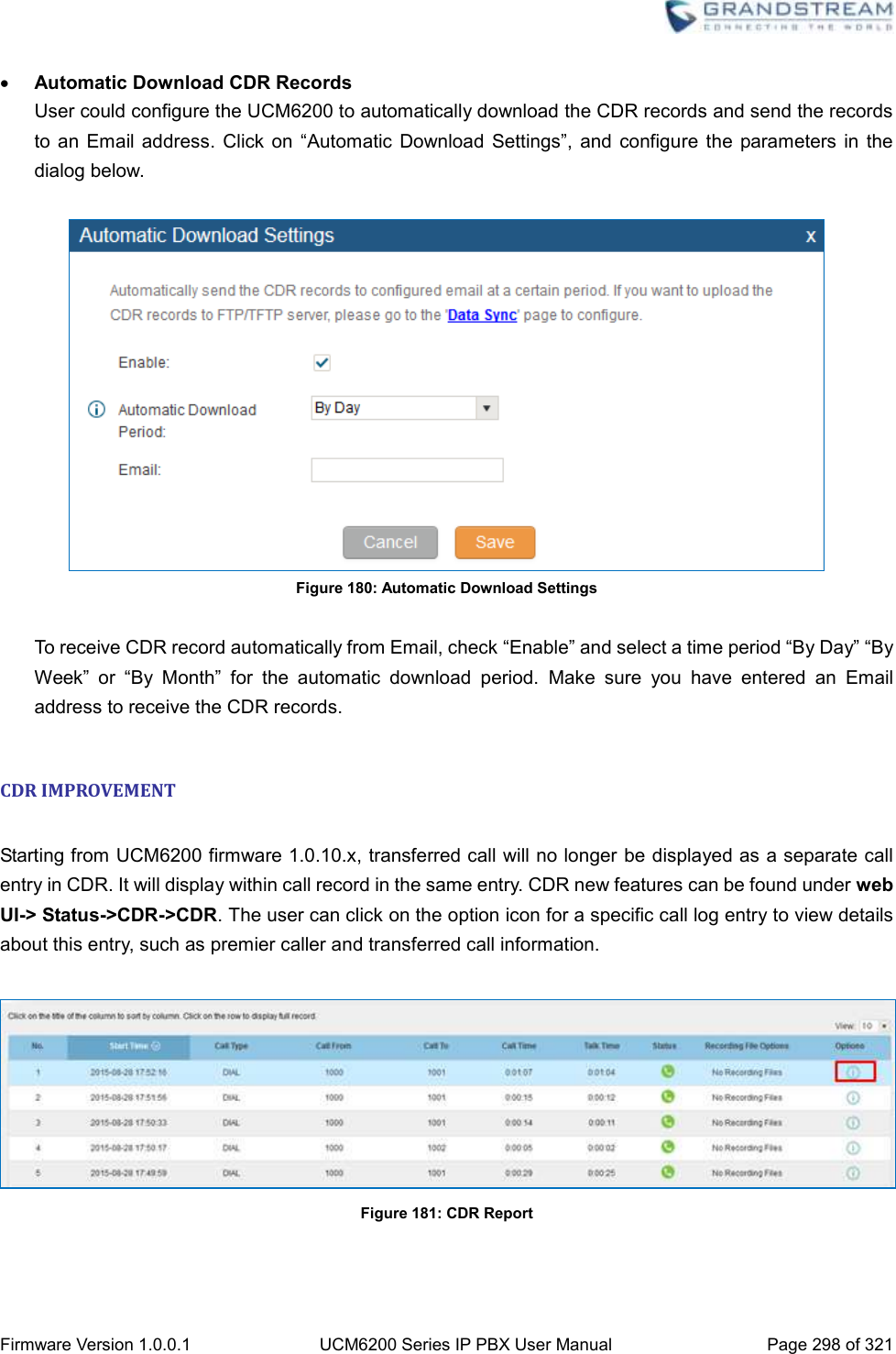
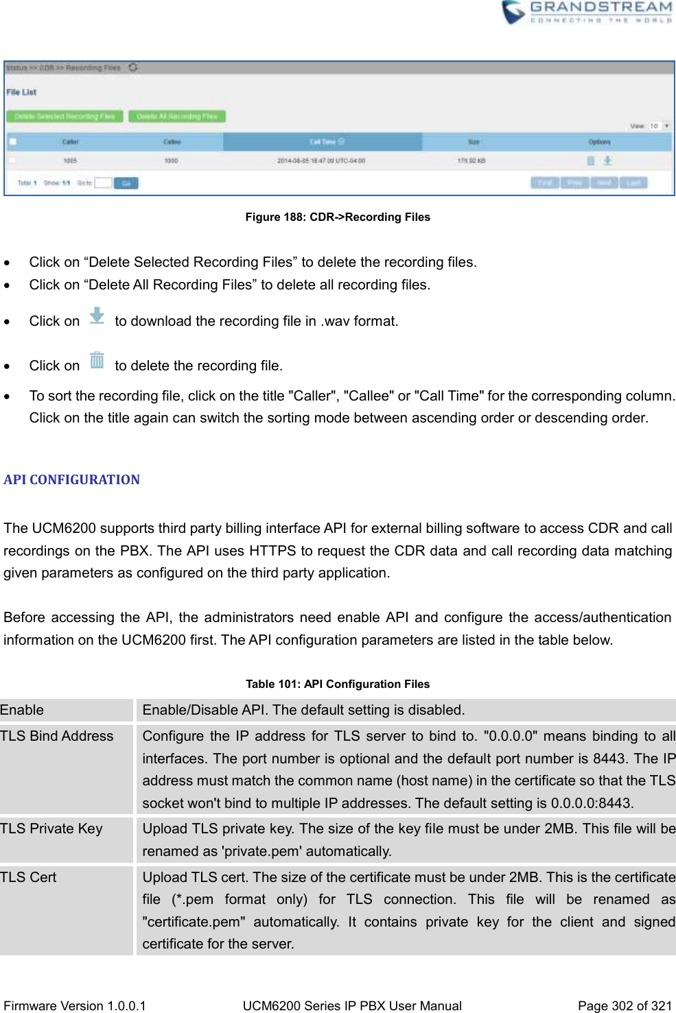
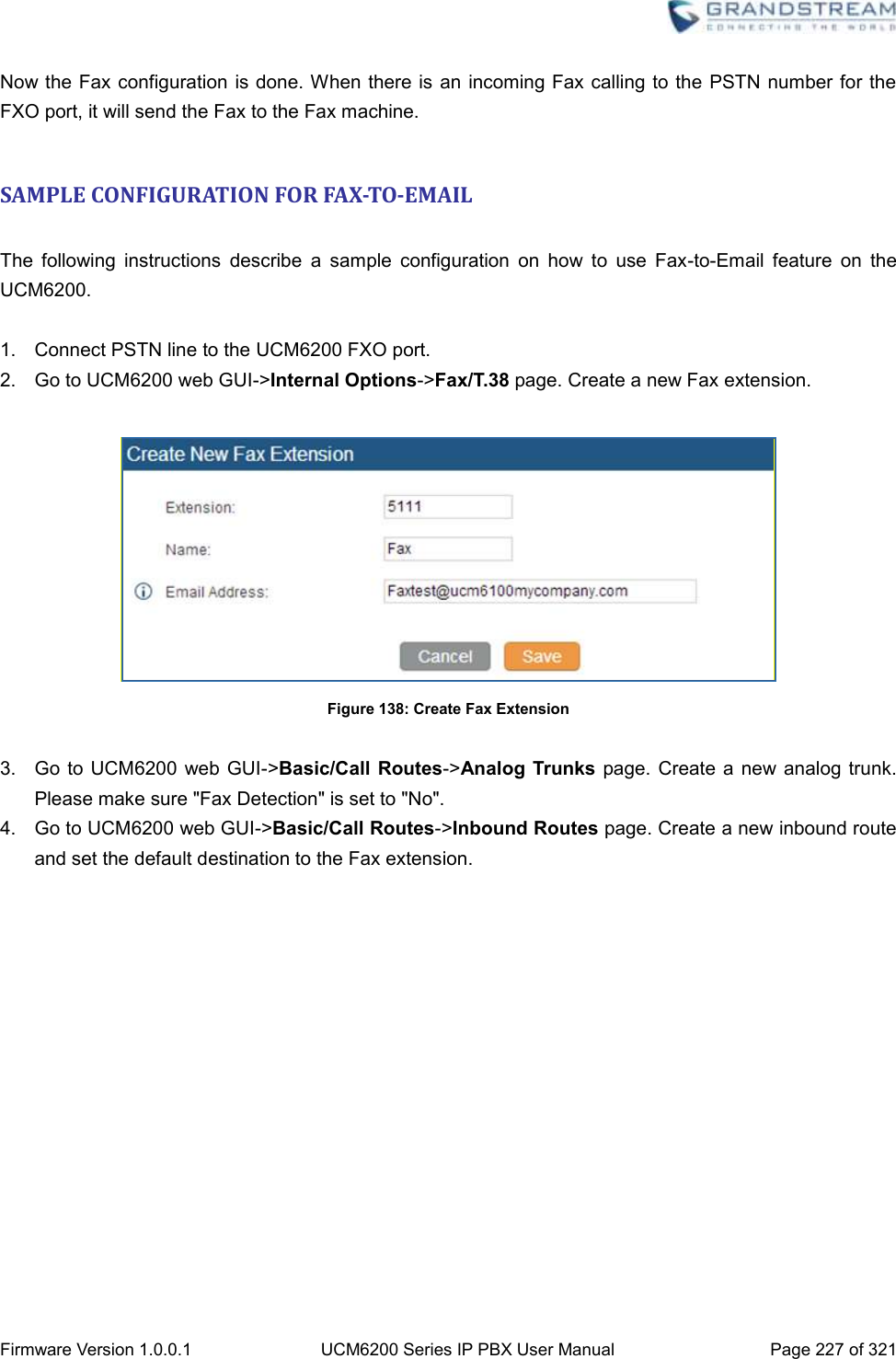
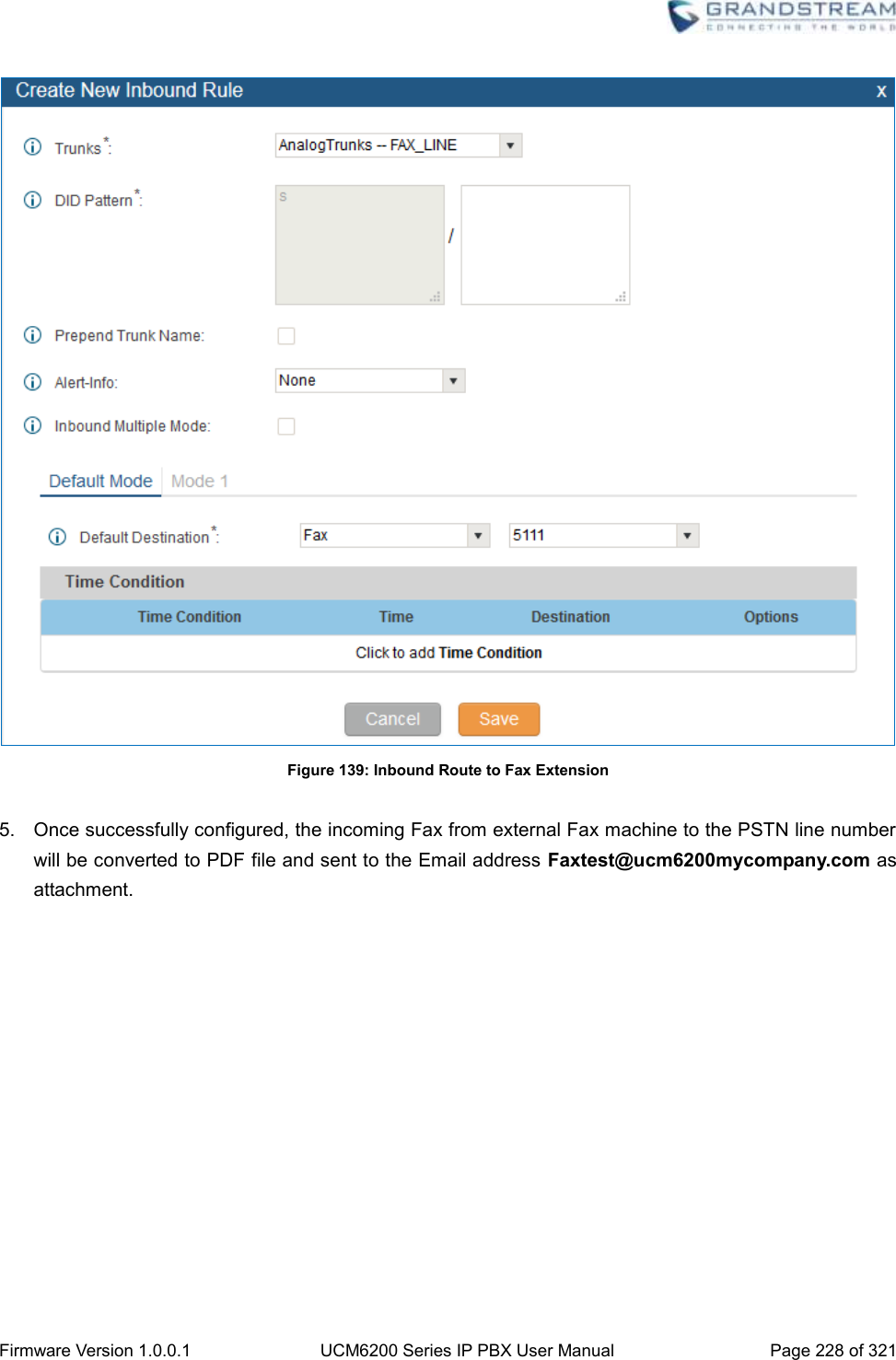
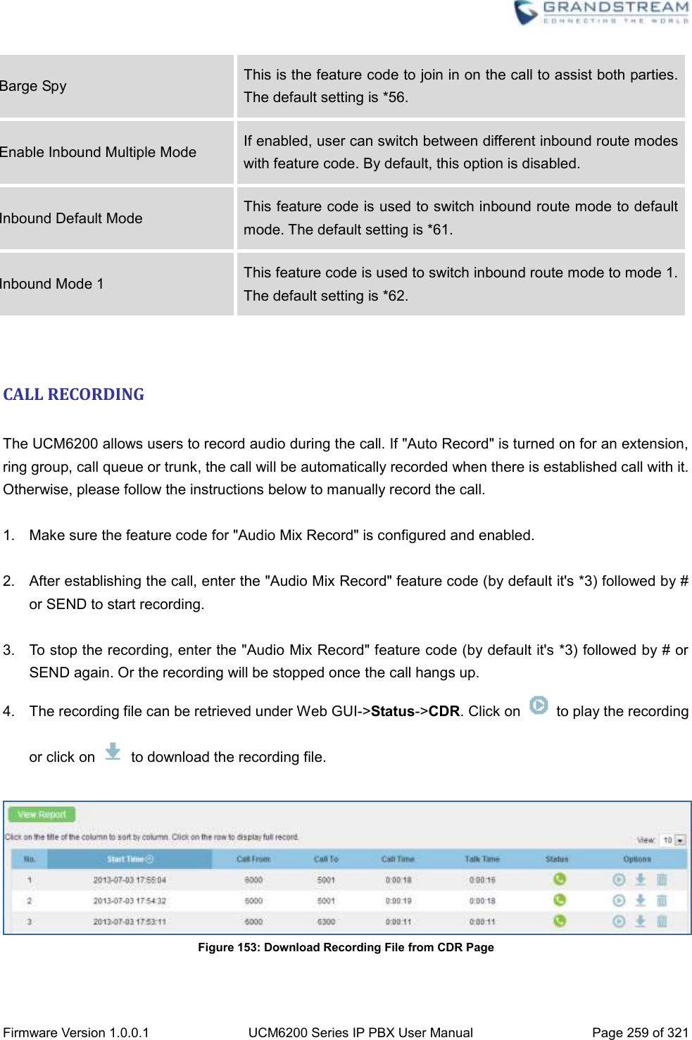
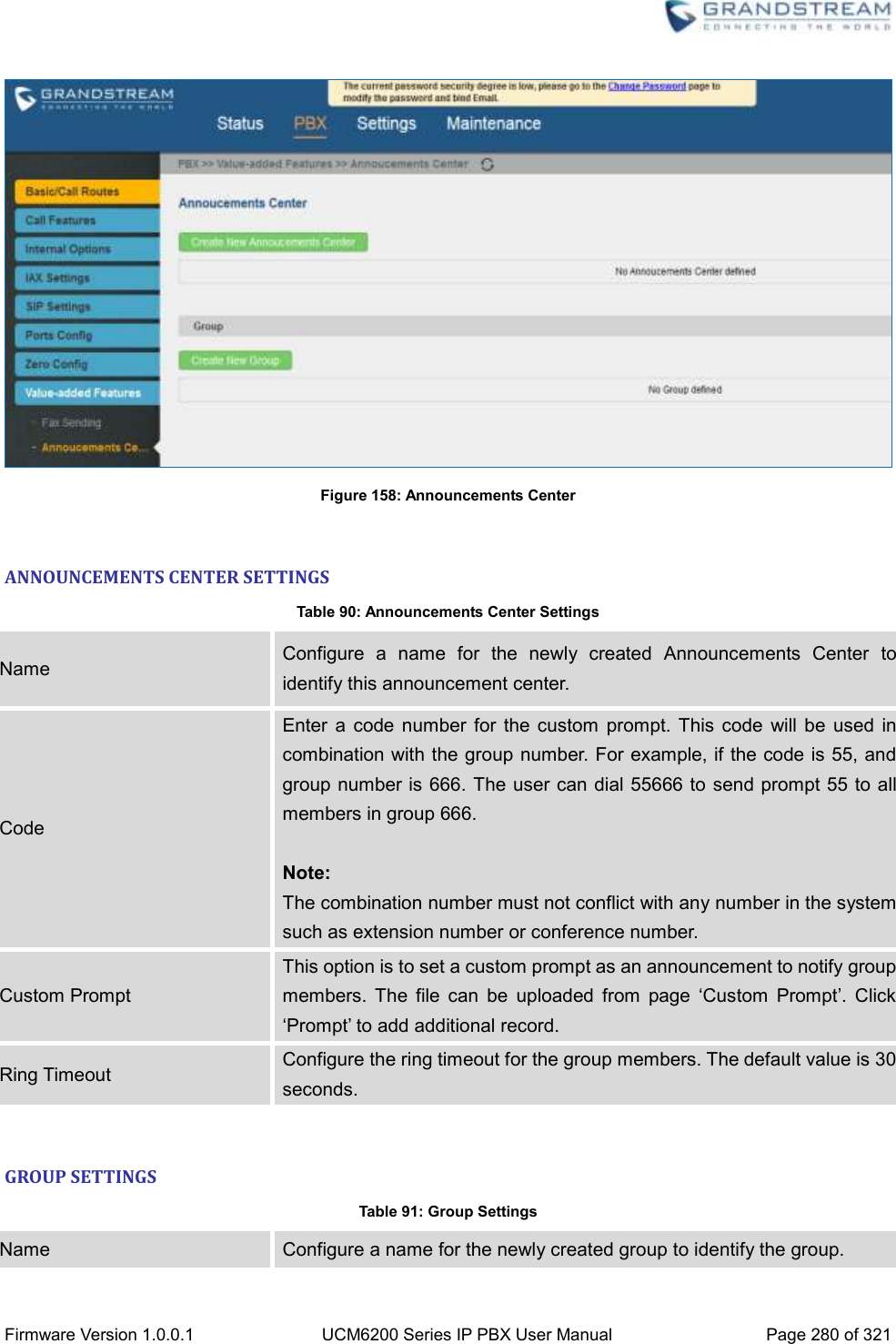
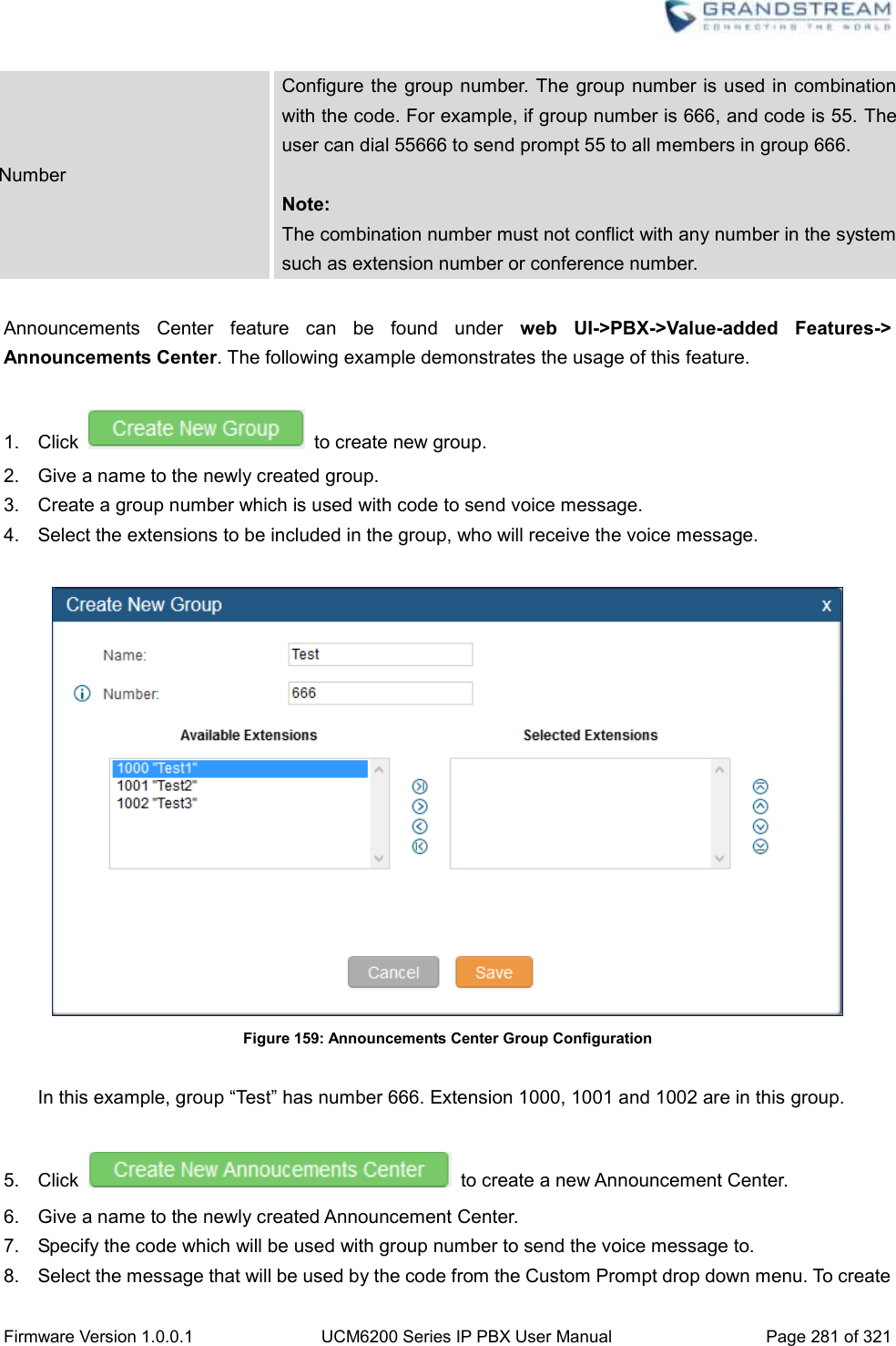
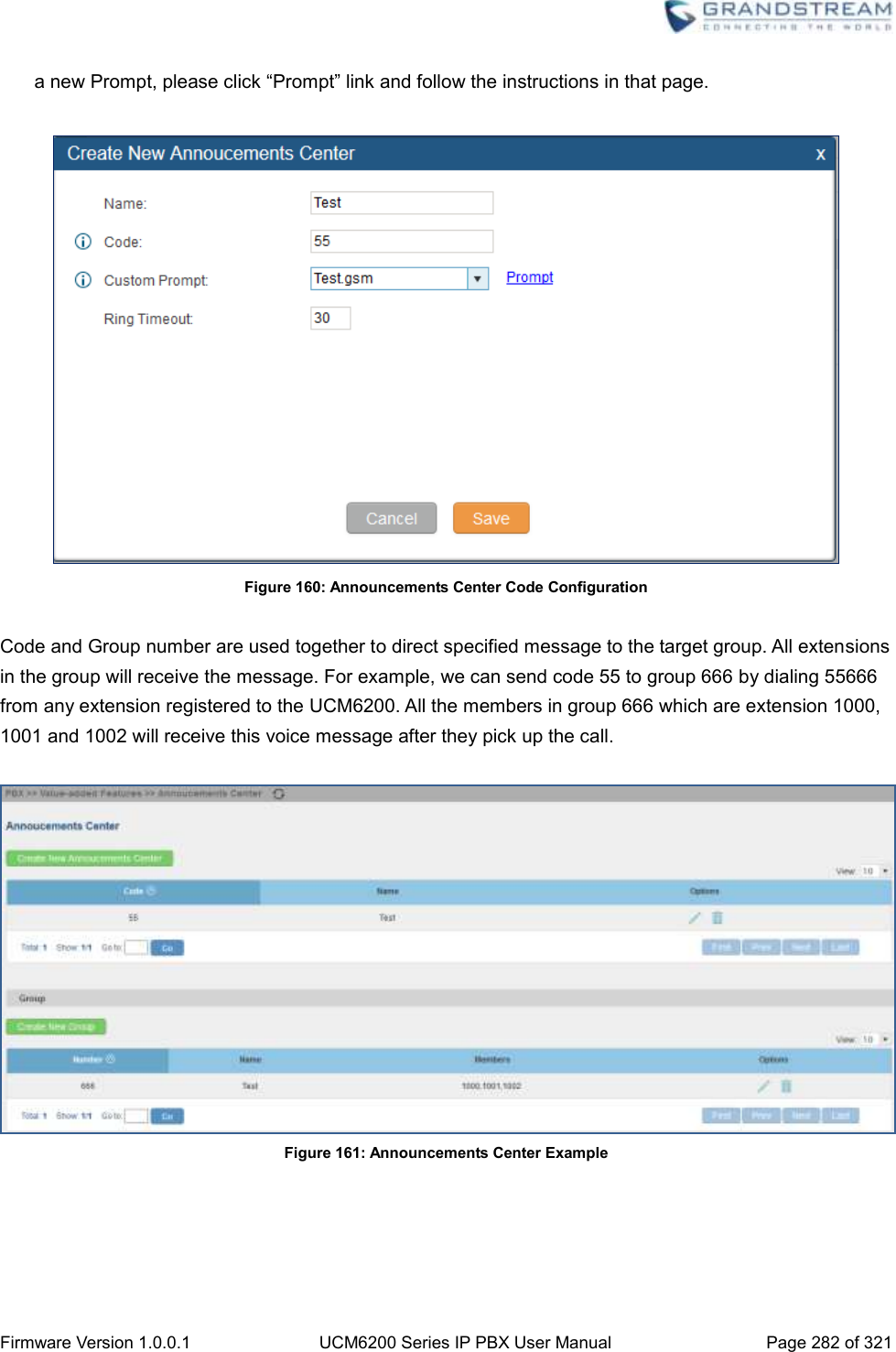
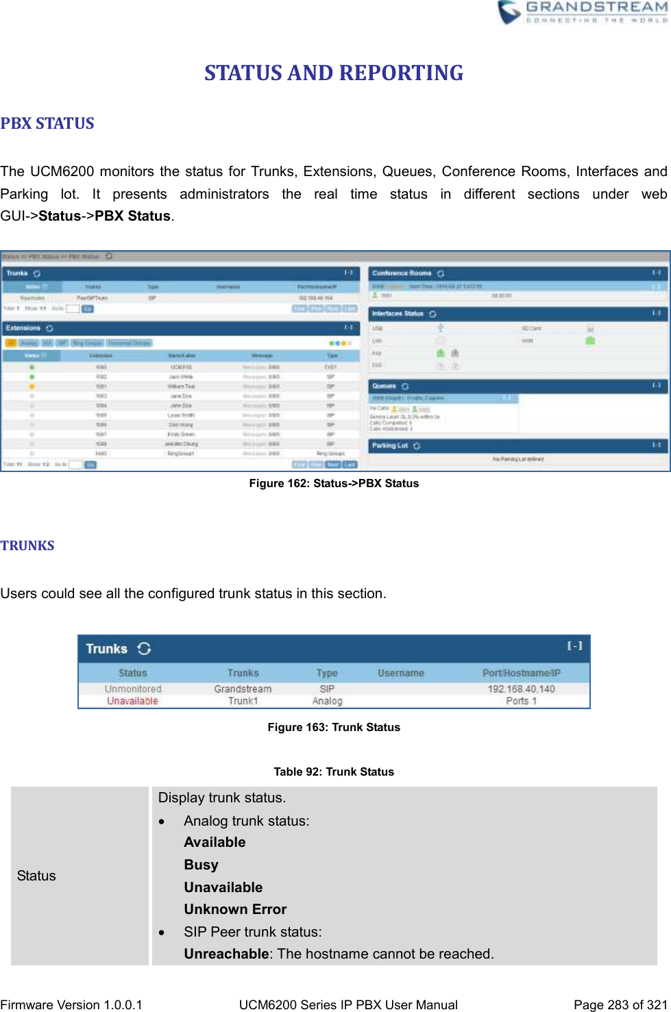
![Firmware Version 1.0.0.1 UCM6200 Series IP PBX User Manual Page 279 of 321 VALUE-ADDED FEATURES FAX SENDING The UCM6200 supports sending Fax via web UI access. This feature can be found on web UI->PBX->Value-added Features->Fax Sending page. In order to send fax, pre-setup for analog trunk and outbound route is required. Please refer to [ANALOG TRUNKS], [VOIP TRUNKS] and [OUTBOUND ROUTES] sections for configuring analog trunk and outbound route. After making sure analog trunk or VoIP Trunk is setup properly and UCM6200 can reach out to PSTN numbers via the trunk, on Fax Sending page, enter the fax number and upload the file to be faxed. Then click on “Send” to start. The progress of sending fax will be displayed in web UI. Users can also view the sending history is in the same web page. Figure 157: Fax Sending in Web UI ANNOUNCEMENTS CENTER The UCM6200 supports Announcements Center feature which allows users to pre-record and store voice message into UCM6200 with a specified code. The users can also create group with specified extensions. When the code and the group number are dialed together in the combination of code + group number, the specified voice message is sent to all group members and only extensions in the group will hear the voice message.](https://usermanual.wiki/Grandstream-Networks/UCM6202/User-Guide-3010507-Page-280.png)
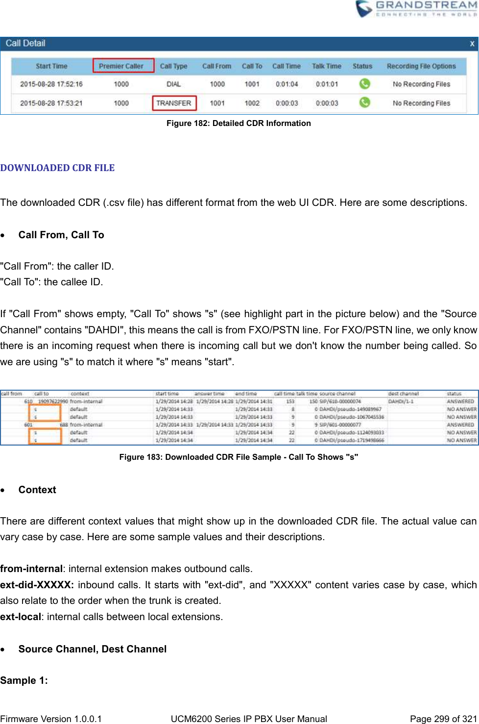
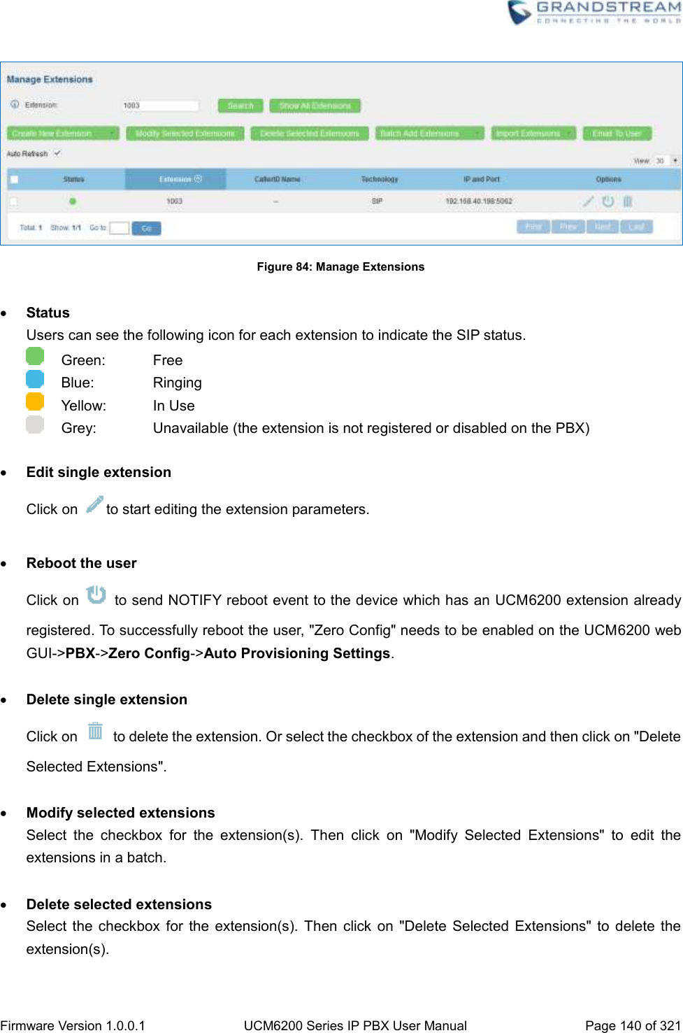
![Firmware Version 1.0.0.1 UCM6200 Series IP PBX User Manual Page 284 of 321 Unmonitored: QUALIFY feature is not turned on to be monitored. Reachable: The hostname can be reached. SIP Register trunk status: Registered Unrecognized Trunk Trunks Display trunk name Type Display trunk Type: Analog SIP IAX Username Display username for this trunk. Port/Hostname/IP Display Port for analog trunk, or Hostname/IP for VoIP (SIP/IAX) trunk. Other operations are also available in trunk status section: Click on "Trunks", the web page will redirect to trunk configuration page which can also be accessed via web GUI->PBX->Basic/Call Routes->Analog Trunks. Click on to refresh the trunk status. Click on [ + ] to expand the status detail table. Click on [ - ] to hide the status detail table. EXTENSIONS Users could see all the configured extension status in this section. Figure 164: Extension Status](https://usermanual.wiki/Grandstream-Networks/UCM6202/User-Guide-3010507-Page-285.png)
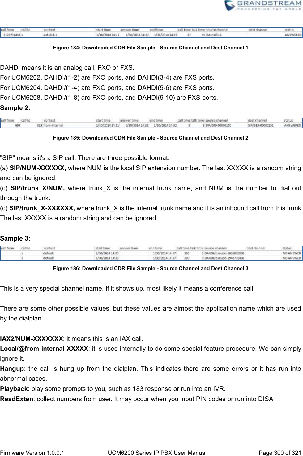
![Firmware Version 1.0.0.1 UCM6200 Series IP PBX User Manual Page 285 of 321 Table 93: Extension Status Status Display extension number (including feature code). The color indicator has the following definitions. Green: Free Blue: Ringing Yellow: In Use Grey: Unavailable Extension Display the extension number. Name/Label First name and last name of the extension. Message Display message status for the extension. Example: 2/4/1 Description: There are 2 urgent messages, 4 messages in total and 1 message that has been already read. Type Displays extension type. SIP User IAX User Analog User Ring Groups Voicemail Groups Other operations are also available in extension status section: Click on "Extensions", the web page will redirect to extension configuration page which can also be accessed via web GUI->PBX->Basic/Call Routes->Extensions. Click on to refresh the extension status. Click on one of the tabs to display the corresponding extensions accordingly. Click on [ + ] to expand the status detail table. Click on [ - ] to hide the status detail table. QUEUES Users could see all the configured call queue status in this section. The following figure shows the call queue 6500 being in used.](https://usermanual.wiki/Grandstream-Networks/UCM6202/User-Guide-3010507-Page-286.png)
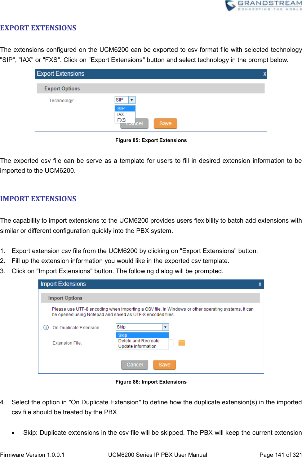
![Firmware Version 1.0.0.1 UCM6200 Series IP PBX User Manual Page 286 of 321 Figure 165: Queue Status The current call status (caller ID, duration), agent status, service level, calls summary (completed/abandoned) are shown for the call queue. The agent status is defined as below. Table 94: Agent Status The agent is available/idle. The agent is ringing. The agent is talking/busy. The agent has been logged out. On the UCM6200, Service Level is defined as the percentage of high-quality calls over all calls in the call queue, where high-quality call means calls answered within 10 seconds. Other operations are also available in queue status section: Click on "Queues", the web page will redirect to call queue configuration page which can also be accessed via web GUI->PBX->Call Features->Call Queue. Click on to refresh the call queue status. Click on [ + ] to expand the call queue detail. Click on [ - ] to hide the call queue detail. CONFERENCE ROOMS Users could see all the conference room status in this section. It shows all the configured conference rooms, current users, call duration for each user and conference call.](https://usermanual.wiki/Grandstream-Networks/UCM6202/User-Guide-3010507-Page-287.png)
![Firmware Version 1.0.0.1 UCM6200 Series IP PBX User Manual Page 287 of 321 Figure 166: Conference Room Status Other operations are also available in conference room status section: Click on "Conference Rooms", the web page will redirect to conference room configuration page which can also be accessed via web GUI->PBX->Call Features->Conference. Click on to refresh the conference room status. Click on [ + ] to expand the conference room details. Click on [ - ] to hide the conference room details. INTERFACES STATUS This section displays interface/port connection status on the UCM6200. The following example shows the interface status for UCM6204 with USB, WAN port, FXS1, FXS2 and FXO1 connected. Figure 167: UCM6204 Interfaces Status Table 95: Interface Status Indicators USB connected. USB disconnected. SD Card connected. SD Card disconnected.](https://usermanual.wiki/Grandstream-Networks/UCM6202/User-Guide-3010507-Page-288.png)
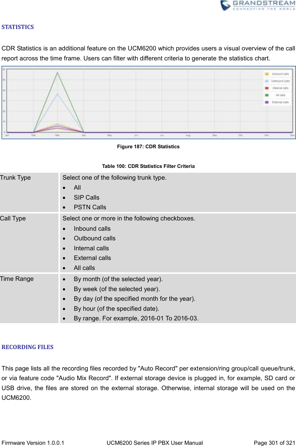
![Firmware Version 1.0.0.1 UCM6200 Series IP PBX User Manual Page 288 of 321 LAN/WAN connected. LAN/WAN not configured. LAN/WAN disconnected. FXS/FXO connected. FXS/FXO waiting. FXS/FXO busy. FXS/FXO not configured. FXS/FXO disconnected. Other operations are also available in interface status section: Click on "Interfaces Status", the web page will redirect to ports configuration page which can also be accessed via web GUI->PBX->Internal Options->Ports Config. Click on to refresh the interface status. Click on [ + ] to expand the interface details. Click on [ - ] to hide the interface details. PARKING LOT The UCM6200 supports call park using feature code. When there is call being parked, this section will display the parking lot status. Figure 168: Parking Lot Status Table 96: Parking Lot Status Caller ID Display the caller ID who parks the call. Channel Display channel for the call park. Extension Display the parking lot number where the call is parked/retrieved. Timeout Display timeout (in seconds) for the parked call. The status page will dynamically update this timer from 120 seconds (default) to 0. When the timer](https://usermanual.wiki/Grandstream-Networks/UCM6202/User-Guide-3010507-Page-289.png)
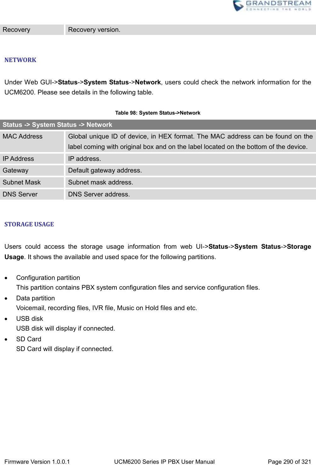
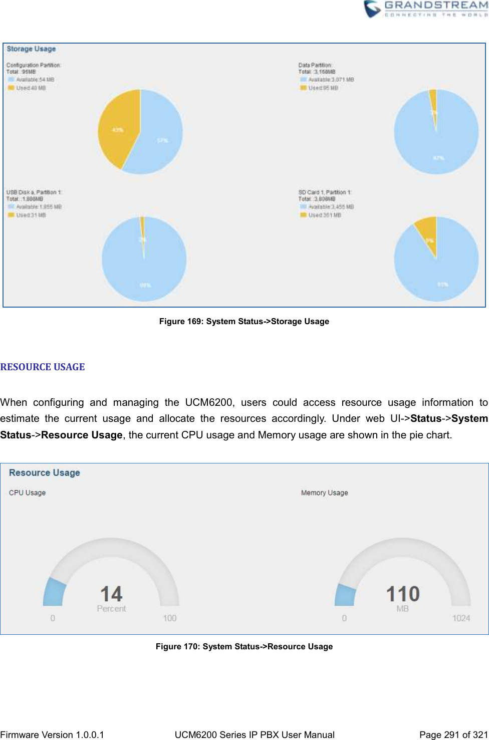
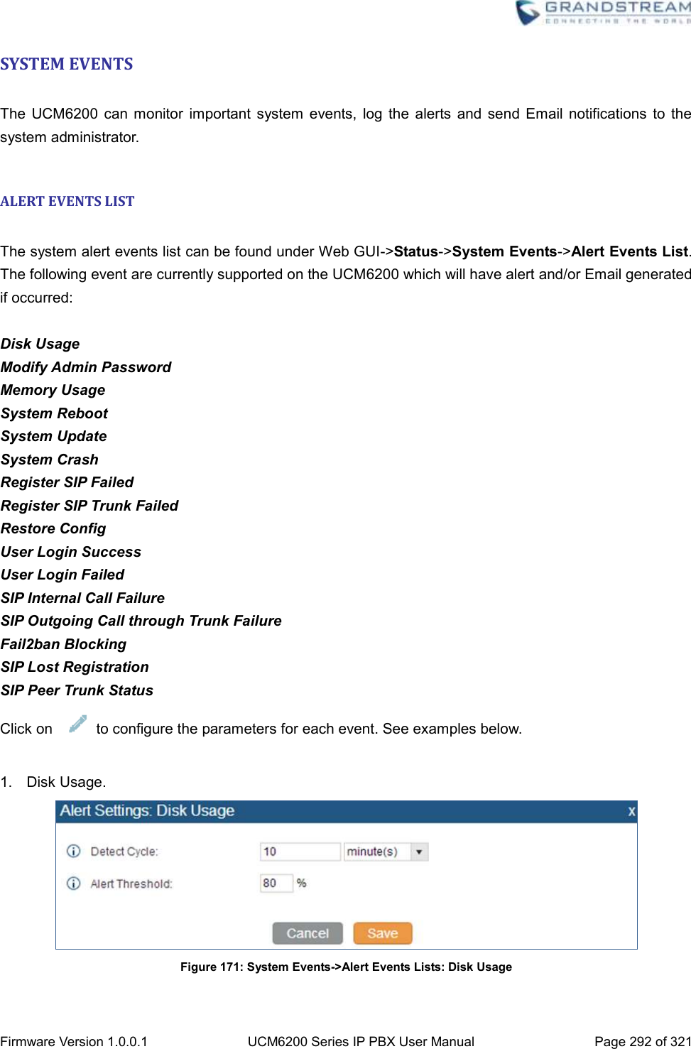
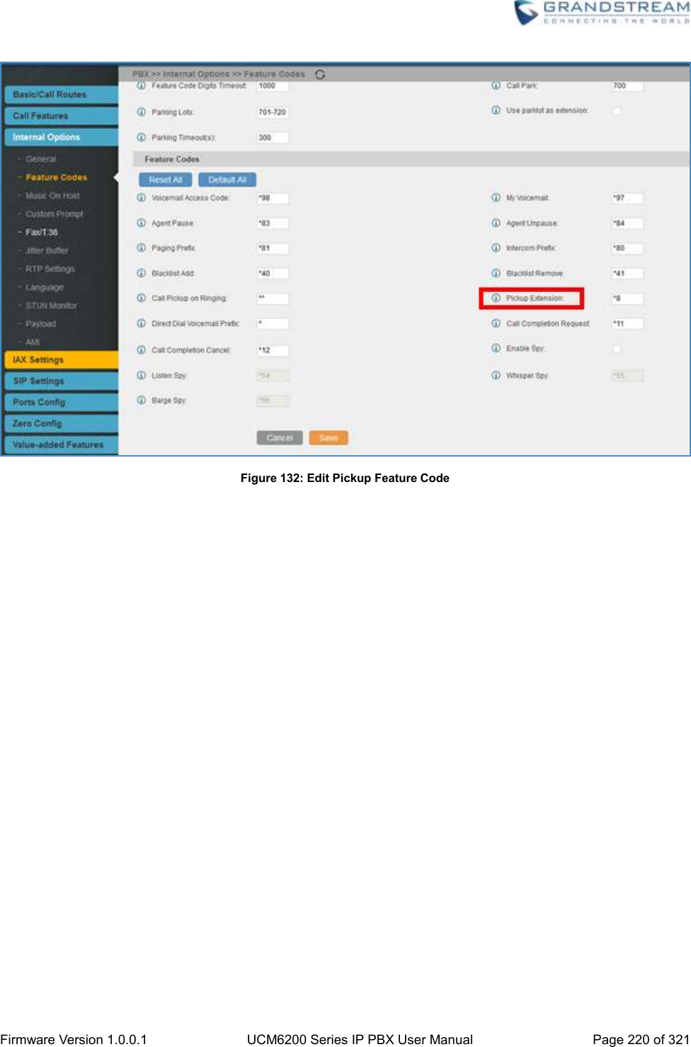
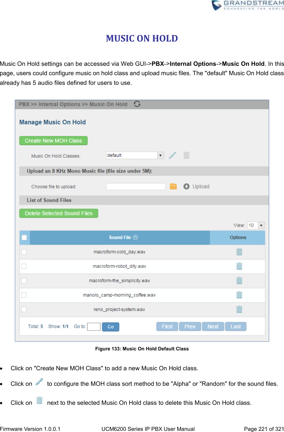
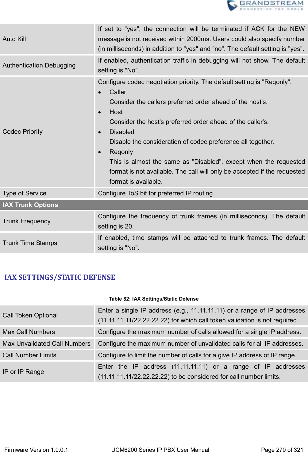
![Firmware Version 1.0.0.1 UCM6200 Series IP PBX User Manual Page 289 of 321 reaches 0, the caller who parks the call will be called back. Other operations are also available in parking lot status section: Click on "Parking Lot", the web page will redirect to feature codes page which can also be accessed via web GUI->PBX->Internal Options->Feature Codes. Click on to refresh the parking lot status. Click on [ + ] to expand the parking lot details. Click on [ - ] to hide the parking details. SYSTEM STATUS The UCM6200 system status can be accessed via Web GUI->Status->System Status, which displays the following system information. General Network Storage Usage Resource Usage GENERAL Under Web GUI->Status->System Status->General, users could check the hardware and software information for the UCM6200. Please see details in the following table. Table 97: System Status->General Status ->System Status -> General Model Product model. Part Number Product part number. System Time Current system time. The current system time is also available on the upper right of each web page. Up Time System up time since the last reboot. Boot Boot version. Core Core version. Base Base version. Program Program version. This is the main software release version.](https://usermanual.wiki/Grandstream-Networks/UCM6202/User-Guide-3010507-Page-290.png)