Graupner Mz 32 Help Reference Manual & 16 V2.0
2019-01-30
: Graupner Mz-32 & Mz-16 Help Reference Manual V2.0 mz-32 & mz-16 Help Reference Manual V2.0 RADIOS
Open the PDF directly: View PDF ![]() .
.
Page Count: 44
- MAIN SCREEN WIDGETS
- BASE Menu
- FUNCTION Menu
- PHASE SET
- PHASE TRIM
- NO DELAY CH
- WING SET
- WING SET DETAIL
- WING TAIL
- WING TAIL DETAIL
- DIFFERENTIAL
- AIR BRAKE
- AIR BRAKE DETAIL
- SNAP ROLL
- SNAP ROLL DETAIL
- THROTTLE CURVE
- PITCH CURVE
- SWASH MIXER
- SWASH OPTION
- HELI MIXER
- HELI MIXER DETAIL
- FREE MIXERS
- FREE MIXERS DETAIL
- CROSS MIXERS
- DIRECT ADJUST
- RING LIMITER
- RING LIMITER DETAIL
- MIX ONLY CHANNEL
- CHANNEL SEQUENCER
- SPECIAL Menu
- SYSTEM Menu
- DISCLAIMER
Help
mz-32 / mz-16 HoTT
Reference Manual
2.4 GHz transmitter
P/N. S1024, S1024.77, S1047, S1047.US

Graupner mz-32 / mz-16 Help Reference Manual
Page 2 of 44 Help-Ref-EN-V1.1
TABLE OF CONTENTS
MAIN SCREEN WIDGETS .................................................................................................... 5
BASE Menu ........................................................................................................................ 6
MODEL LIST ..................................................................................................................... 6
MODEL LIST DETAIL .......................................................................................................... 6
NEW MODEL ..................................................................................................................... 6
MODEL TYPE ..................................................................................................................... 7
RF SET ............................................................................................................................. 8
SERVO SET ..................................................................................................................... 10
SERVO SET DETAIL .......................................................................................................... 10
CONTROL SET.................................................................................................................. 11
CONTROL SET DETAIL ...................................................................................................... 11
TRIM SET ........................................................................................................................ 12
THROTTLE CUT ................................................................................................................ 12
DUAL RATE EXPO ............................................................................................................. 13
DUAL RATE EXPO DETAIL .................................................................................................. 13
SWITCH SET .................................................................................................................... 14
TIMERS SET .................................................................................................................... 14
TIMERS SET DETAILS ....................................................................................................... 15
TIMER SET LAP DETAILS ................................................................................................... 15
FAIL SAFE ....................................................................................................................... 16
OUTPUT SWAP ................................................................................................................. 16
SERVO VIEW ................................................................................................................... 16
TRIM VIEW ...................................................................................................................... 17
TIME INFO ...................................................................................................................... 17
FUNCTION Menu ............................................................................................................... 18
PHASE SET ...................................................................................................................... 18
PHASE TRIM .................................................................................................................... 18
NO DELAY CH .................................................................................................................. 19
WING SET ....................................................................................................................... 19
WING SET DETAIL ............................................................................................................ 19
WING TAIL ...................................................................................................................... 20
WING TAIL DETAIL ........................................................................................................... 20
DIFFERENTIAL ................................................................................................................. 21
AIR BRAKE ...................................................................................................................... 21
AIR BRAKE DETAIL ........................................................................................................... 22
SNAP ROLL ...................................................................................................................... 22
SNAP ROLL DETAIL........................................................................................................... 22
THROTTLE CURVE ............................................................................................................ 23
PITCH CURVE .................................................................................................................. 23
SWASH MIXER ................................................................................................................. 24
SWASH OPTION ............................................................................................................... 24

Graupner mz-32 / mz-16 Help Reference Manual
Page 3 of 44 Help-Ref-EN-V1.1
HELI MIXER ..................................................................................................................... 24
HELI MIXER DETAIL .......................................................................................................... 25
FREE MIXERS .................................................................................................................. 25
FREE MIXERS DETAIL ....................................................................................................... 26
CROSS MIXERS ................................................................................................................ 26
DIRECT ADJUST ............................................................................................................... 27
RING LIMITER.................................................................................................................. 28
RING LIMITER DETAIL ...................................................................................................... 28
MIX ONLY CHANNEL ......................................................................................................... 28
CHANNEL SEQUENCER ...................................................................................................... 29
SPECIAL Menu .................................................................................................................. 30
TELEMETRY ..................................................................................................................... 30
RF STATUS VIEW ............................................................................................................. 30
SETTINGS AND DATA VIEW ............................................................................................... 31
SYSTEM NOTICE .............................................................................................................. 31
USER NOTICE .................................................................................................................. 32
SENSOR NOTICE .............................................................................................................. 32
CONTROL NOTICE ............................................................................................................ 33
VOICE NOTICE ................................................................................................................. 34
CONTROL SWITCH ........................................................................................................... 34
LOGICAL SWITCH ............................................................................................................ 35
COMBI SWITCH ............................................................................................................... 35
DIGITAL SWITCH ............................................................................................................. 35
SENSOR SWITCH ............................................................................................................. 36
VARIO TONE .................................................................................................................... 37
TRAINER ......................................................................................................................... 37
TRAINER CHANNELS ......................................................................................................... 38
MP3 ................................................................................................................................ 38
SYSTEM Menu ................................................................................................................... 39
SYSTEM SET .................................................................................................................... 39
DISPLAY SET ................................................................................................................... 40
SOUND SET ..................................................................................................................... 40
I/O SET .......................................................................................................................... 40
STICK SET ...................................................................................................................... 41
FILE MANAGER ................................................................................................................ 41
USB ................................................................................................................................ 41
WLAN & GPS ................................................................................................................... 42
BT & COM Port ................................................................................................................. 42
INFO & UPDATE ............................................................................................................... 43
DISCLAIMER ..................................................................................................................... 44

Graupner mz-32 / mz-16 Help Reference Manual
Page 4 of 44 Help-Ref-EN-V1.1
REVISIONS
Document V1.0 – Firmware 1.019
• Initial Release
Document V1.1 – Firmware 1.0.29
• Added – Direct Adjust Function
• Added – Sensor Switch Function
• Changed – System Set
Document V2.0 – Firmware 1.0.31
• Changed – Document is now generic
Graupner mz-32 / mz-16 Help Reference Manual
Page 5 of 44 Help-Ref-EN-V1.1
MAIN SCREEN WIDGETS
Your radio home screen is designed around Widgets.
There are a total of 6 decks that can be designed with
widgets. Each widget fits inside a 1, 2, or 4
presentation block. Navigation between the decks is
done by using the arrow keys (2 upper keys left of
screen) or you can assign your own navigation keys
in the System menu.
You can delete all Widgets or clear the Widget Data
for each deck by pressing the reset icon. (Circle with
an arrow next to Help icon in the upper right corner of
the screen).
You can restore the default decks by selecting
System, then System Set, and tapping on the field of Model Preset – Widget.
A deck can be global for all models or specific to a model.
You can have a different set of decks for each of your models.
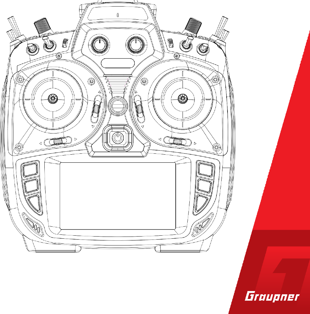
To access the Widget editor, touch and briefly hold on the field you would like to place a
Widget. The Widget editor will open with available widgets to choose from.
In case you placed a Widget at the wrong place or want to change it, touch and briefly hold
on the Widget to change or delete it.
Telemetry Widgets are active Widgets that receive real-time information from the radio
system.
For example, if your receiver voltage drops below a certain value the Widget will change its
color and alert you with a voice notification.
When you touch and hold on the widget a dialog open showing how many warnings were
issued, what the current voltage is as well as the minimal and maximal voltage recorded.
This works the same for all telemetry widgets.
Taping the clear field resets all values.
W01S1
Graupner mz-32 / mz-16 Help Reference Manual
Page 6 of 44 Help-Ref-EN-V1.1
BASE Menu
MODEL LIST
In the Model List menu, you can create a new model or
select and load an existing one.
To create a new model, tap on the number next to the
model name. A selection toolbar will show with the
available options.
Tap the + icon to create a new model.
Tap on the copy icon to copy an existing model.
After tapping the + icon, a keypad will show where you
can enter your model name. Tapping the return key
brings you to the New Model selection menu.
To change the view selection of available model types,
tap on the model type icon in the upper center of the screen to activate the desired filter.
You can sort the model list by name, creation date or bind group by tapping on the table
header.
B01S1
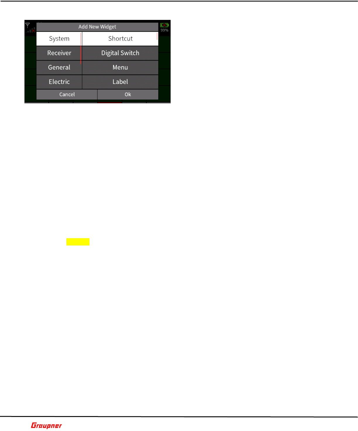
MODEL LIST DETAIL
By tapping on the model Name, additional details about
the selected model are displayed prior to loading and
activating the model.
The Date and Time fields show when the model was
created, and the Model Time shows how long the model
has been actively used.
The Bind Group field shows to which group this model
belongs (check the RF Set menu for additional
information).
The Bind Info fields show how many receivers the
selected model is bound to and how many channels
each bound receiver has.
The bottom fields show the model configurations such as model type, wing type and tail
type. To load and activate the model, tap the Select field.
B01S2
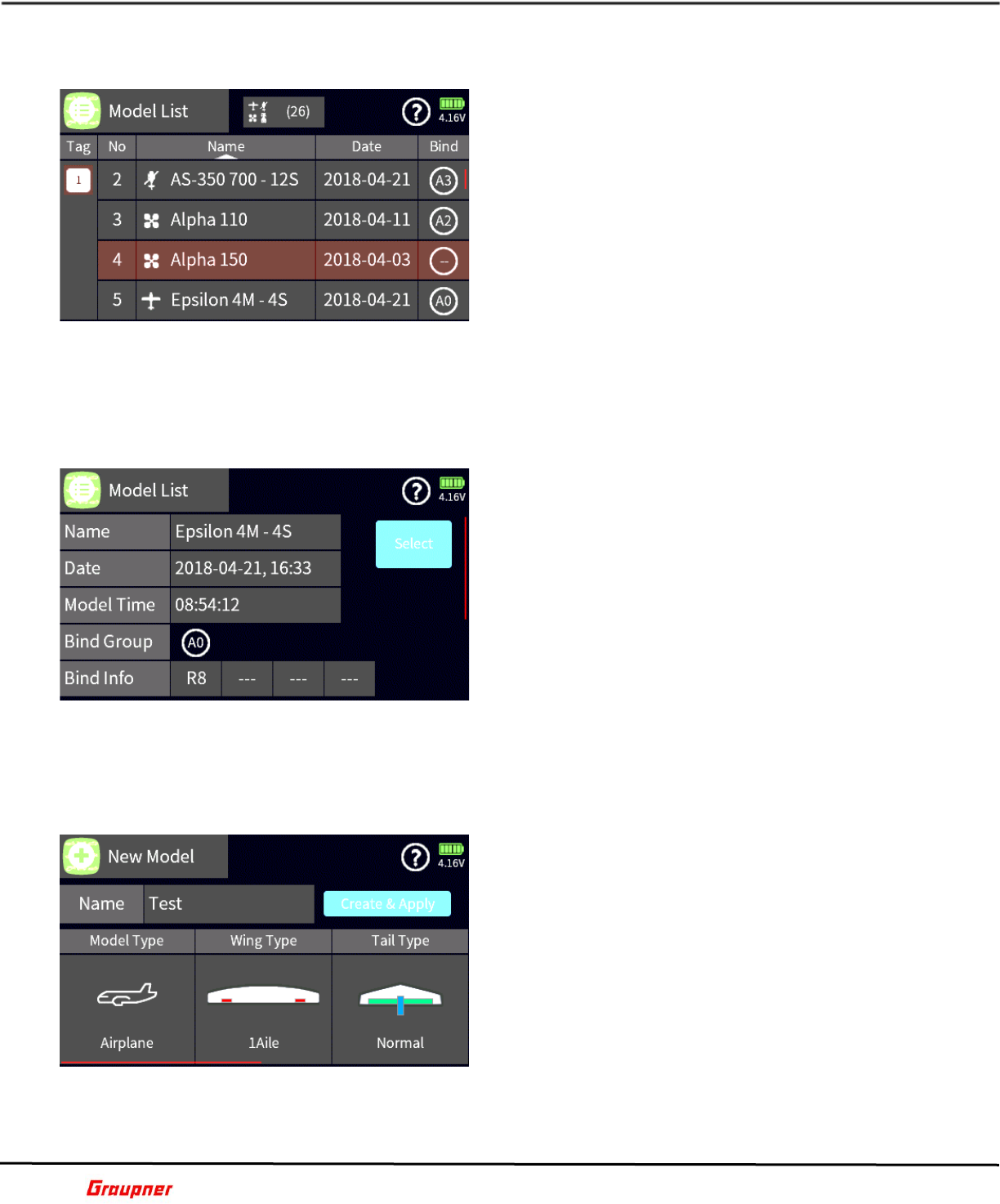
NEW MODEL
The New Model menu can only be accessed from the
Model List menu when creating a new model.
Tap on the Model Type icon to select your model type.
Each model type will have different selection options.
The following example is for airplanes.
Tap on the Wing Type icon to select your airplane’s
wing type. If your wing type is delta tap on the delta
icon symbol to change the wing type selection.
Tap on the Tail Type icon to choose your tail type.
Tap on the engine type to select how many engines
your airplane has.
Tap on Throttle Minimum to change the throttle direction.
A selection of None (only available for Airplanes) is for models without a motor, such as a
sailplane. A selection of Rear causes the throttle channel to increase as the throttle control
Graupner mz-32 / mz-16 Help Reference Manual
Page 7 of 44 Help-Ref-EN-V1.1
is increased. A selection of Front causes the throttle channel to decrease as the throttle
control is increased.
Tap on the stick mode to change your stick mode configuration.
When done tap on the Create & Apply button, which will create the model and reinitialize
the radio to load the new model.
You can make later changes to the model configuration from the Model Type menu.
B01S3
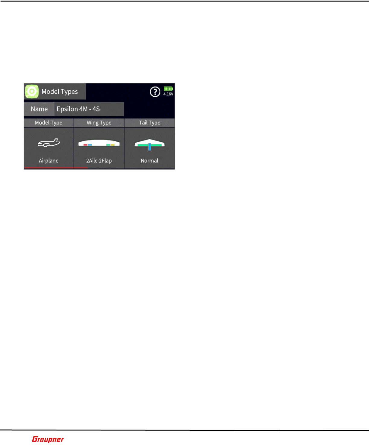
MODEL TYPE
In the Model Type menu, you can change the existing
model configuration or rename the model.
Rename Model
Tap on the model name to bring up the keypad where
you can enter your new model name. When finished,
tap on return key which brings you back to the model
type selection menu.
Change Model Type
Tap on the Model Type icon to select your model type.
Each model type will have different selection options.
All Models
Tap on Throttle Minimum to change the throttle direction. A selection of None (only
available for Airplanes) is for models without a motor, such as a sailplane. A selection of
Rear causes the throttle channel to increase as the throttle control is increased. A selection
of Front causes the throttle channel to decrease as the throttle control is increased.
Tap on the stick mode to change your stick mode configuration.
Airplanes
Tap on the Wing Type icon to select your airplane’s wing type. If your wing type is delta
tap on the delta icon symbol to change the wing type selection.
Tap on the Tail Type icon to choose your tail type.
Tap on Engine to select how many engines your airplane has.
Brake Function controls the switching point for the brake control. Tap on the input field
(default throttle) to select the control for the brake channel. To set the offset value for
brake activation, move the control to the desired position and tap the offset field to store
the value.
Helicopters
Tap on Swash Type to select the number of swash plate servos and their geometry.
Tap on Linear Swash to set whether to compensate for the arc of the servos when changing
collective pitch. Set the value to Linear to enable the compensation or Normal to disable it.
Tap on Thro. Limit to enable (Limit) or disable (Unlimit) the channel 12 throttle limiter.
Selecting Unlimit will also free up channel 12 for other functions.
When finished tap on the Model Types icon to exit the menu.
B02S1
Graupner mz-32 / mz-16 Help Reference Manual
Page 8 of 44 Help-Ref-EN-V1.1
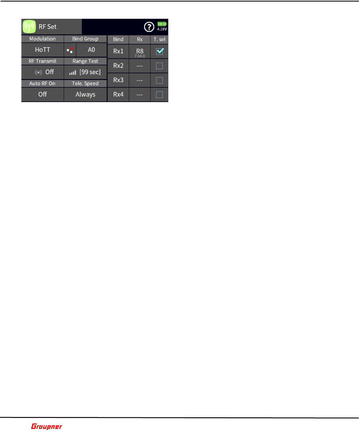
RF SET
In the RF Set menu you will manage all RF and
Telemetry communications between the radio and
receiver as well as binding your model to the radio.
BINDING
Depending on your radio model you can bind up to 4
receivers to your model. The binding process requires
you to place the receiver in bind mode, which can be
done by pressing the SET button on the receiver. After
2-3 seconds, you can tap the bind button on the radio.
You need to bind RX1 first. When binding has been
successful the Rx column will show the channel count
of the receiver and below in small letters the current receiver firmware version. For
example, a GR-24 will show as R12 and a GR-12L will show as R6.
Depending on the receiver model you may need to follow a slightly different procedure to
successfully bind the receiver to the radio.
Bind Method A:
Press the SET button and keep it pressed for 2-3 seconds and press the bind button on the
radio.
GR-12/GR-18/GR-24 PRO/GR-16(L)/GR-24(L)/GR-32(L):
Green LED on – Receiver bound
GR-12L:
Red LED off – Receiver bound
Bind Method B:
Receiver goes automatically into binding mode (Flight Controllers after 15 seconds with
blinking red LED)
GR-10C/GR-12SC & SH/Falcon 12/Falcon 12 PLUS/Alpha 110/S1038, S1039
Red LED off – Receiver bound
Notes:
If binding was not successful, repeat the bind procedure.
Make sure that the receiver is at least 50cm/2ft away from the radio.
Verify that the power source is sufficient to power the receiver.
Make sure that the power polarity is properly connected. The GR-12 6 channel
receivers require that the negative wire is facing up.
Verify that the bind SET button is properly pressed.
RX
Tap on the selected blue Rx field (a receiver must be bound) and a dialog will show with
the available channels and channel numbers for that receiver. Here you can remap the
channels or assign a digital switch output by tapping on the icon next to the channel
number.
Tap on the channel you want to remap and use the arrow keys to map the channel to
another channel.
Tapping on the Reset button will restore all channels to default.
T.Sel (Telemetry Select)
Tap on the receiver which you want to designate as the active telemetry receiver. There
can be only one telemetry receiver active at any time.
Modulation
The default modulation is set for HoTT (Hopping Telemetry Transmission)

Graupner mz-32 / mz-16 Help Reference Manual
Page 9 of 44 Help-Ref-EN-V1.1
RF Transmit
Default is set to off. Tapping the off field will turn the RF to on. If no receiver is found the
radio will sound an error and the Graupner front logo will blink in blue.
Auto RF On
Setting this field to on will activate the RF immediately after the model is loaded bypassing
the RF On/Off dialog shown on startup when the Auto RF is switched to Off.
Bind Group
For an unbound model memory, the default is the next free binding group. However, as
long as the model memory is unbound, this specification can be changed by tapping the
icon on the “Bind Group” field. You can select from the following options:
„Global“ enables the receiver to respond to the transmitter signal on a non-exclusive basis.
What this means is that any other receiver that is bounds as global will respond to the
transmitter signal of another model memory that was also bound as global. This can be
used in situations where for example you have multiple models that are all the same and
do not need different model memory settings.
„Group“ enables the receiver to respond exclusively to the group ID assigned during
binding. For example, if you bind a receiver to bind group A0, that receiver will not respond
to a signal from the transmitter of a model memory that was bound global or, for example,
as group C2.
You can bind another model memory also under bind group C2, which will result in one
model memory sharing two receivers under a single bind. When both receivers are turned
on, they will respond simultaneously to the same control inputs of the transmitter.
The use case for this is, for example, during competition when one airplane becomes
inoperative and you would like to continue the contest using an identical airplane without
switching model memories on your transmitter to avoid losing time. All you need to do is
power the other airplane and wait for the receiver to establish the bind.
Range Test
When the range test starts, the output of the transmitter decreases significantly. A practical
functional test can therefore be performed at a distance of less than 100 m. After the end
of the range test, the transmitter switches back to full output power and the range test
signal tone stops.
Range test step-by-step
Verify that the receiver and transmitter are communicating properly and that all control
surfaces are functional.
Place the model on a flat surface (cement, mowed lawn or ground) with the receiver
antenna at least 15 cm above ground.
Hold the transmitter at hip level at a slight distance from your body.
Start the range test in the „RF Set“ menu by tapping the icon in the “Range Test” field.
The time display begins to count down and a beep will sound throughout the entire range
test.
Move away from the model within the given 99 seconds range test and move the control
sticks while maintaining visual contact.
If you notice an interruption in the connection at any time within a distance of about 50 m
/ 160 ft, try to reproduce it.
If possible, switch on an existing motor, to additionally check the interference resistance.
Carry out the extended range test before starting up your model, simulating all the control
movements occurring in practice. To guarantee a safe model operation, the range must
always be at least 50 m / 160 ft on the ground.
Graupner mz-32 / mz-16 Help Reference Manual
Page 10 of 44 Help-Ref-EN-V1.1
Telemetry Speed
In those situations where, for example, two airplane models are about to be operated at
close proximity to another controlled by two separate transmitters, you may choose to
reduce or eliminate the telemetry back channel of one of the models to avoid potential
interference. Situations that may need to be evaluated include drones that have a separate
transmitter for control and camera operations, or airplanes that tow or carry other
airplanes, can be all pick up interference from the telemetry downlink transmission.
Experiment with the proper telemetry period value for your situation.
You can reduce the amount of telemetry data transmitted back from the receiver to the
radio as follows:
Always: Transmits telemetry data with each data packet.
4 Times: Transmits telemetry data each 40ms
8 Times: Transmits telemetry data each 80ms
Off: No telemetry data is transmitted.
B03S1
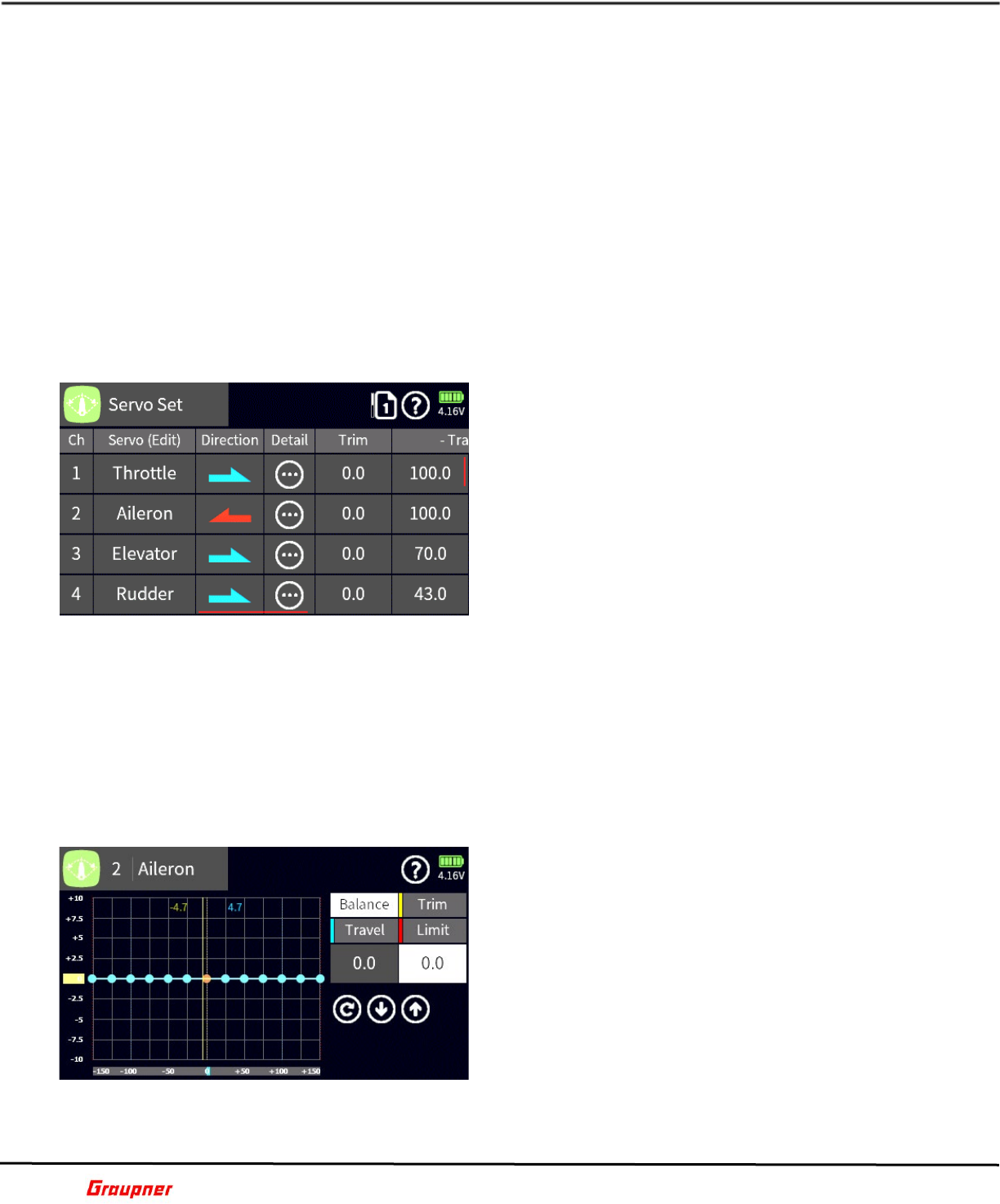
SERVO SET
Please be careful when making changes to the throttle
direction as it may unexpectedly start the motor.
Always ensure that the propeller or main battery are
disconnected.
In the Servo Set menu you can make all basic
adjustments to your servos to optimally tune them to
your model.
The first two columns show the channel number and
channel name. Tapping on the channel number or
name shows the edit bar where you can name or
rename your channel name. Choose a proper channel
name that will help you identify each channel function.
The Direction field enables you to reverse the channel direction.
Tapping on the Detail icon lets you fine tune servo parameters.
The Trim field is your sub trim value for centering your servo or control surfaces.
The Travel and Limit fields let you adjust servo throws and maximal servo deflection. Set
the deflection to a value where the servo does not mechanically bind.
The value in the Delay fields will determine the speed of the control movement.
All settings in the Servo Set menu are applied globally and are not Phase dependent.
SERVO SET DETAIL
The Servo Set Detail menu enables you to fine tune
your servo settings.
Balance: Here you can adjust the servo travel to ensure
that each control surface is moving in an identical way.
To make changes to a curve point, move the control
over the point to select or by tapping on the input field
under the balance column.
When a curve point is selected, it will turn orange. Now
you can either move the curve point using the arrow
keys or with the orange slider tab along the vertical
axis.
Trim: your sub trim for centering your servo or control surfaces.
Travel: sets the desired travel range for your servo.
Graupner mz-32 / mz-16 Help Reference Manual
Page 11 of 44 Help-Ref-EN-V1.1
Limit: sets the maximal servo deflection to a value where the servo does not mechanically
bind.
B04S2
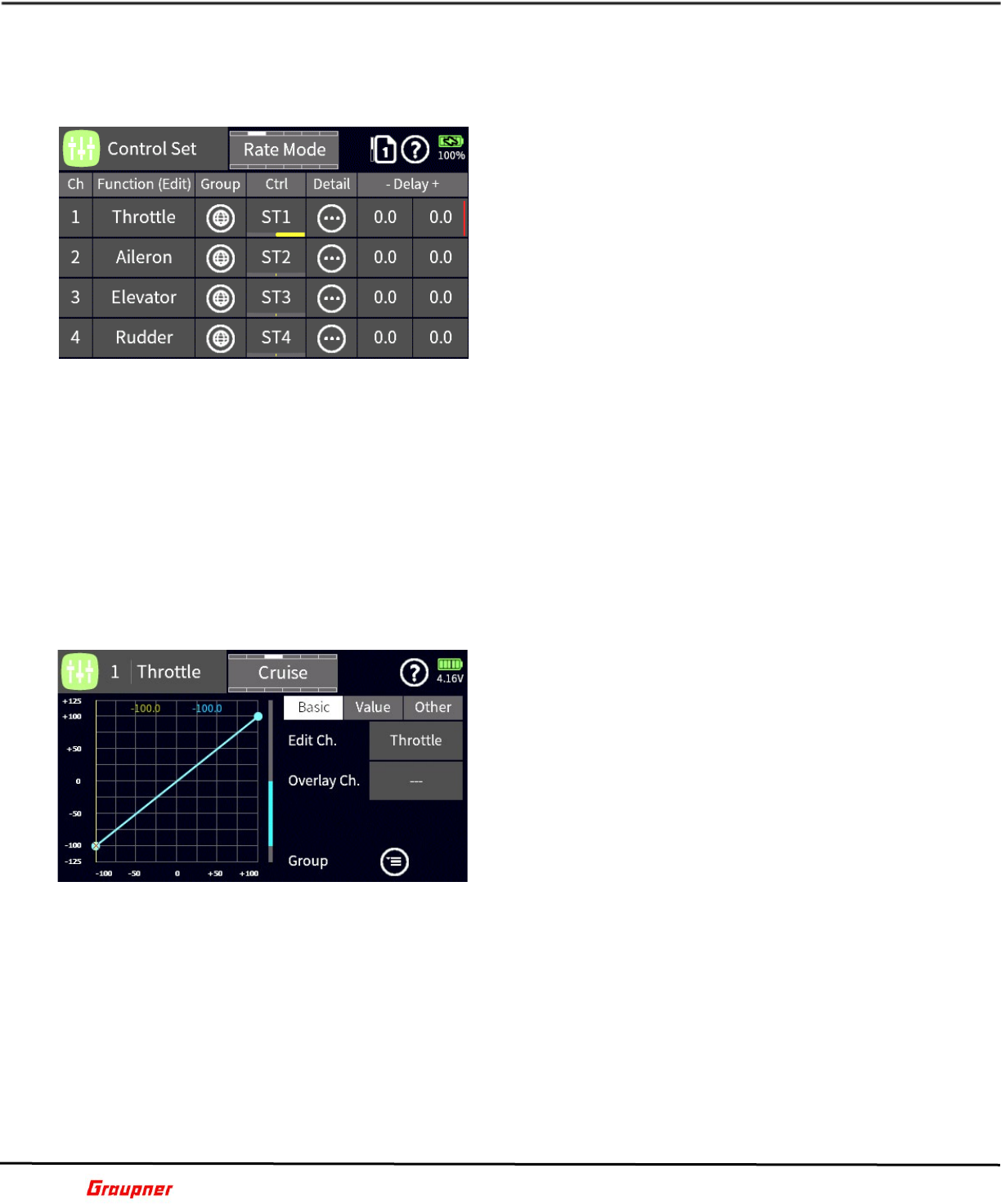
CONTROL SET
In the Control Set menu, you can set the controls such
as switches, sliders and buttons that will activate and
operate each channel. When setting up your model, the
system automatically assigns controls depending on
your model setup. It is not recommended changing
these pre-set controls.
Scrolling the control set menu down (swipe the screen
up or down) will show the first 16 available channels.
To view channels 17 – 32 tap on the page icon next to
the question mark.
To change the channel name, tap on the channel
number or channel name which reveals the edit bar.
A control for a channel can be set globally or phase dependent allowing you to change the
control used depending on the flight phase.
To assign a control to a channel, tap on the channel control field. Moving a control will
automatically record that control as the main control. You can have different input control
types assigned to each channel.
Additional control types can be created in the special menu.
The values in the delay fields will determine the speed of the control movement.
Tapping on the detail icon provides access to different curve types to fine tune your channel
behavior.
B06S1
CONTROL SET DETAIL
The Control Set detail menu provides various curve
types that can influence servo travel as well as channel
offsets.
The basic menu displays the active channel and
whether the channel is global or phase dependent. The
overlay channel field provides access to a field selection
menu where you can pick another channel to overlay
the existing channel. If the channel curves are
different, a brown graph line will show the differences
between each channel. This can be helpful when trying
to create identical curves between multiple channels.
In the other menu, you can select the curve type
(linear, flat and multi point). Tap on the curve type icon to change the curve type. You can
select the spline type by tapping on the spline icon.
In the value menu you can set the curve (travel) behavior of the channel.
Depending on the curve type selected you can move the curve over the Y axis or X axis
and change each curve point or offset.
To change a curve point, move the control to select the point so that it becomes active.
You can make changes by tapping on the X and Y fields arrow keys or you can slide the
colored tabs along the X and Y axes.
Adding or removing curve points can be done by moving the control over the curve point
and, when highlighted, tapping the minus key for delete, or by positioning the control cursor
over a point along the curve and tapping the plus key for adding a point.
Graupner mz-32 / mz-16 Help Reference Manual
Page 12 of 44 Help-Ref-EN-V1.1
B06S2
TRIM SET
In the Trim Set menu, you can set the trim behavior
for each of your trims, giving you the most optimal
configuration for your trim settings.
You can have up to 8 different trims for each of your
flight controls. To add a new trim, tap on a number in
the number column to bring up the selection toolbar
and tap the + icon. You will need to select a channel
for which you would like to set up the trim.
To add a control, tap on the Ctrl field to select the
control type you will be using for that channel.
Tapping the Function name permits the re assignment
of the current line settings to a different control function (channel).
The Group icon will set the trim as global or phase dependent.
The Value field shows the current value of the trim position for that channel.
Tapping on the Store field will copy the current trim setting to memory and reset the trim
value back to zero. This enables you to try different trim settings and view the differences
between the stored and current trim settings.
You can select from five different trim types depending on your needs and situation.
Linear decrease of trim impact on both sides of the neutral position.
Even change of trim impact over control range.
Linear decrease of trim impact towards neutral position on lower part of the control
range.
Linear decrease of trim impact over entire control range.
Inverted linear decrease of trim impact over entire range.
The Travel field value determines the maximum trim travel.
B07S1
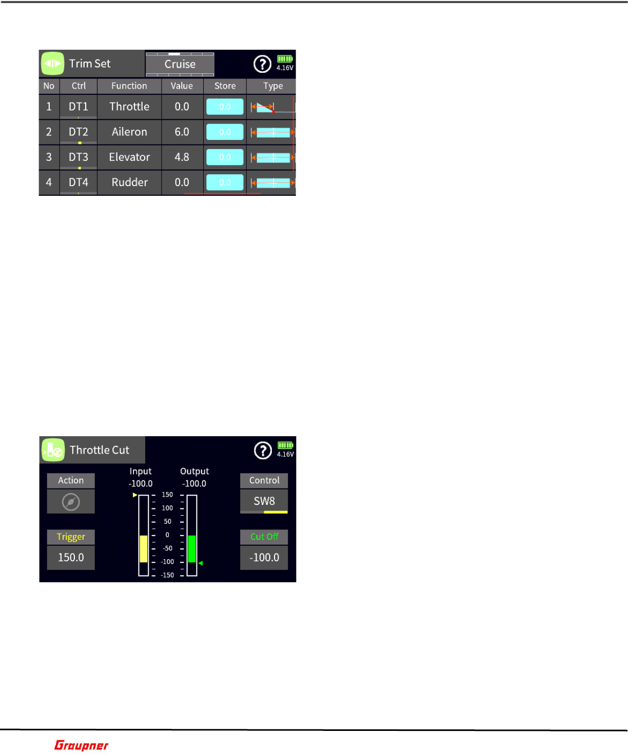
THROTTLE CUT
The Throttle Cut menu provides an easy way to control
your throttle on/off position.
The Control field determines which control is going to
be used for the throttle cut.
The Cut Off value determines at which position the
throttle cut will occur. For example, on gas motors you
would like to have your idle position at -100 but your
cutoff at -130.
The Trigger value determines the threshold position
when the throttle cut is engaged.
The Action field shows the active state of the throttle
cut.
B08S1
Graupner mz-32 / mz-16 Help Reference Manual
Page 13 of 44 Help-Ref-EN-V1.1
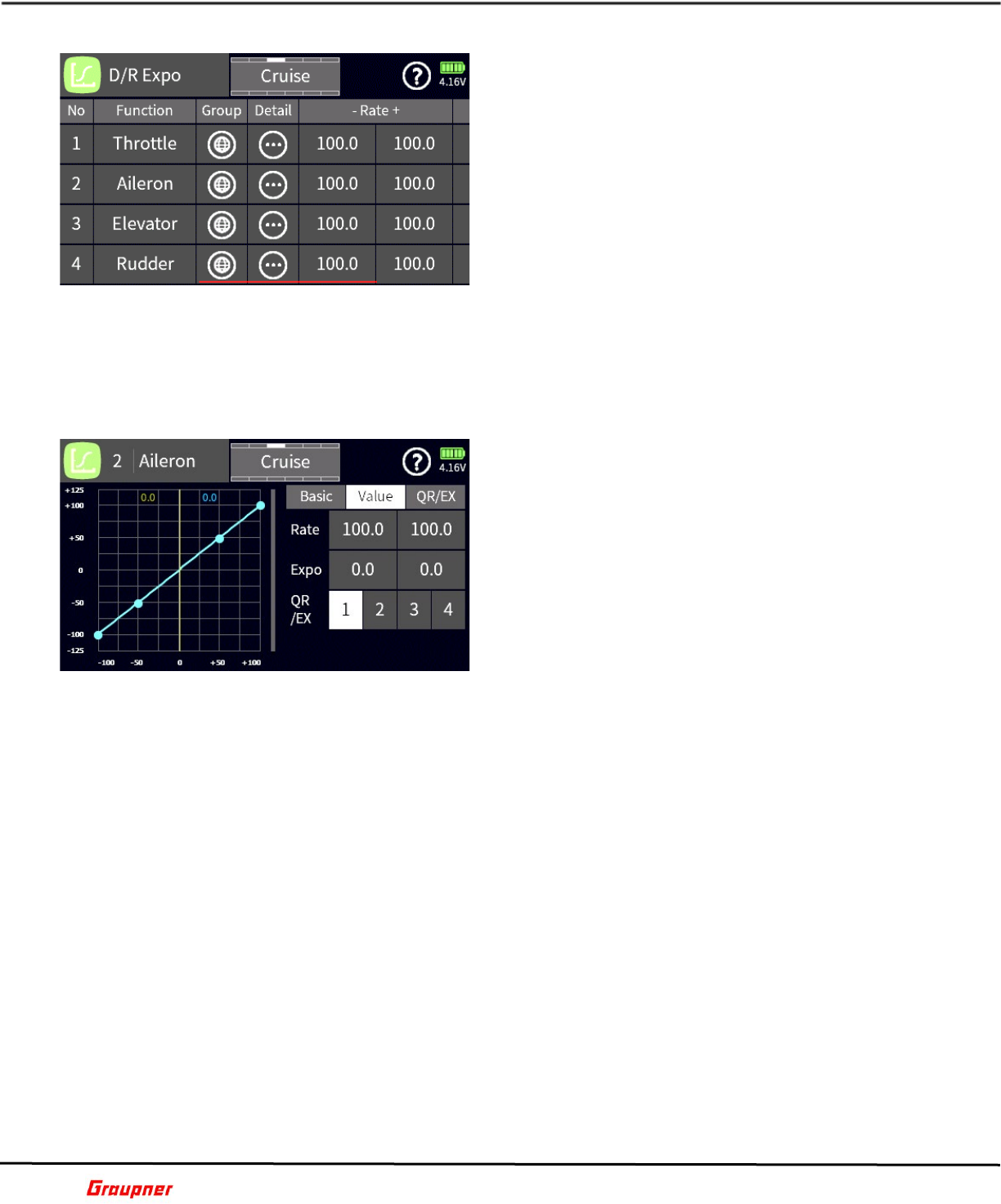
DUAL RATE EXPO
The D/R Expo menu enables you to set up control rates
and exponential rates for each control surface. You can
have up to 8 different control rates where each has four
different state values.
To add another rate, tap on a number in the number
column to bring up the selection toolbar and tap the +
icon. You will need to select a channel for which you
would like to set up rates. Tapping the Function name
permits the re assignment of the current line settings
to a different control function (channel).
The Group column will set the rate as global or phase
dependent.
In the rate and expo column, you can set the minimum and maximum deflection rates and
exponential values.
Tap on the detail icon to access the detail settings for this menu.
B09S1
DUAL RATE EXPO DETAIL
In the Dual Rate Detail menu, you can assign the rates
and switches that will operate your dual, triple or quad
rates.
The detail menu has three sub menu settings.
BASIC
Edit Ch. – Shows the current active channel.
Overlay Ch. – Provides access to a secondary channel
you can lay over the current channel to compare
channel curve settings.
Curve Type – Tapping on the curve icon changes the
active curve type.
Group – Tapping on the group icon changes the current function from global or phase
dependent.
VALUE
Rate – Tapping on the value fields displays the control toolbar on the bottom. Use the link
icon to synchronize the value fields. Changing the values is done with the keys. Use the
reset icon to reset values back to their default.
Expo - Tap on the expo value field to set the amount of desired expo. Note that, depending
on the selected curve type, you can have a single or dual expo setting.
QR/EX - You can assign up to four rates for each control surface. Tap on the field number
which is associated with the assigned control number to edit the rates.
QR/EX
To assign a control to activate a rate, tap on the control field. The select control input dialog
will appear, where you can select the control you would like to use.
B09S2
Graupner mz-32 / mz-16 Help Reference Manual
Page 14 of 44 Help-Ref-EN-V1.1
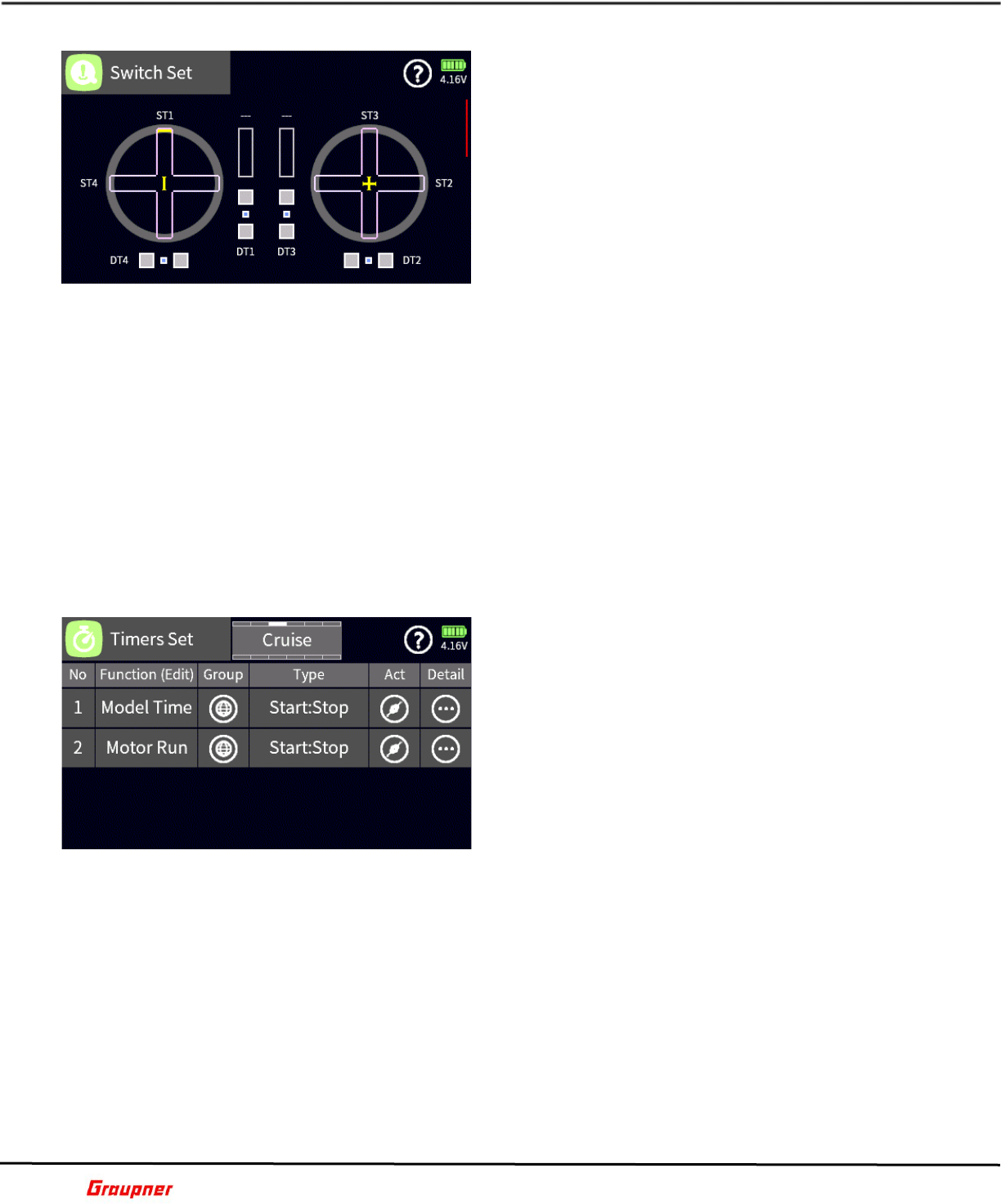
SWITCH SET
In the Switch Set menu, you can set the switching
point for controls, sliders and switches that can be used
for activating mixes and controls when a logic control
is used. It also allows you to set the trim steps and
speed for the digital trims that are used with control
surfaces such as ailerons and elevator.
Each trim and control can be independently set. To
view the detail menu, tap on the DT, ST, LV or DV
control.
In the configuration dialog you can set the following
parameters.
Switching Position – The default is set at 75% for each travel direction. This indicates that
when the control is moved past the +75% or -75% position, a trigger event will happen
that can be used with a logical switch. Lowering the values will cause the trigger point to
be closer to the center point of the control.
Digital Trim – The default values will determine how many steps a digital trim control will
have and how fast it will travel. Setting the steps to zero will disable the digital trim travel.
The switch set menu has additional pages that can be accessed with the arrow keys (top 2
keys left of screen) or by swiping the screen.
The secondary screen shows the current position of the digital trims (DT), knobs (DV),
levers (LV) and switches (SW). Moving each control or switch will animate the control on
the screen while tapping on the control will open the configuration dialog.
The additional screens on the switch set menu are for future development.
B13S1
TIMERS SET
Depending on your radio model you can create up to 6
timers for time or lap recording. Timers can be either
global or phase dependent.
Adding a new timer is done by tapping on the + sign
or on the number of an existing entry to bring up the
selection toolbar.
When tapping on the + sign, the timer type dialog
appears where you can select the type of timer, lap or
start/stop timer.
When the selection toolbar is active, you can perform
delete, re-order or rename functions.
The group column shows if the timer is global or phase dependent. To change group status,
tap on the group icon.
You can change the timer type by tapping on the type column.
The Act icon indicates if the timer is active or disabled.
Tapping on the Detail icon opens the timer set detail menu.
B10S1
Graupner mz-32 / mz-16 Help Reference Manual
Page 15 of 44 Help-Ref-EN-V1.1
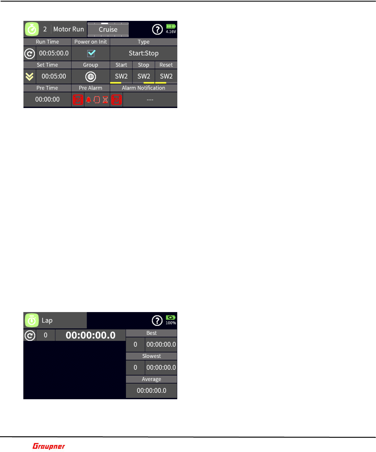
TIMERS SET DETAILS
In the Timer detail menu, you can set all the details for
your timer.
Run Time - Shows the total time the timer has been
running. You can reset the time by either tapping on
the reset icon or by assigning a control.
Set Time – Tapping on the Set Time field will bring up
the time dialog to set the time for the timer to run. A
timer can either count up or count down. To change
the count type, tap on the arrow key.
Pre Time – Tapping on the Pre-Time field allows you to
set a time for when you would like to start receiving
cues from the Pre-Alarm settings. This is usually done during the last phase of the timer
countdown.
Pre Alarm – The Pre Alarm settings determine the type and frequency of the alarms received
during the final countdown. Tapping on the vibrating icon will activate the vibration
feedback. You can choose from up to 10 different vibration types. Tapping on the pre-alarm
field will display the pre-alarm dialog with the following options:
Mode – determines if the notifications are voice or beep types.
Cycle – determines how often they are repeated.
Countdown – determines if the timer will provide a countdown during the last 10 seconds
of the timer run.
Alarm Notification – Tapping on the vibrating icon will activate the vibration feedback when
the timer reaches its countdown end. Tapping on the voice field will bring up the file
manager from where you can select a voice file to play at countdown end.
Power Init – Checking the power init box will clear the timer each time the model is loaded.
When left unchecked the last timer value will remain active when the model is loaded.
Group – Tapping on the group icon will change the timer from group to phase dependent.
Type – Tapping on the type field brings up the timer type dialog to change the active timer
type. When a lap timer type is selected, a timer detail icon will show to access the laps
detail menu.
Start/Stop/Reset – Tapping on any of the fields will bring up the input control dialog for
controlling the timer.
B10S2
TIMER SET LAP DETAILS
In the timer lap detail menu, you can review the lap
time for each lap recorded at its trigger point.
In the top bar, the total time is shown with the total
laps recorded. The reset icon resets and clears all lap
times.
Best – shows the best lap time and best lap number.
Slowest - shows the slowest lap time and slowest lap
number.
Average – shows the average of between the best and
slowest lap number.
B10S3
Graupner mz-32 / mz-16 Help Reference Manual
Page 16 of 44 Help-Ref-EN-V1.1
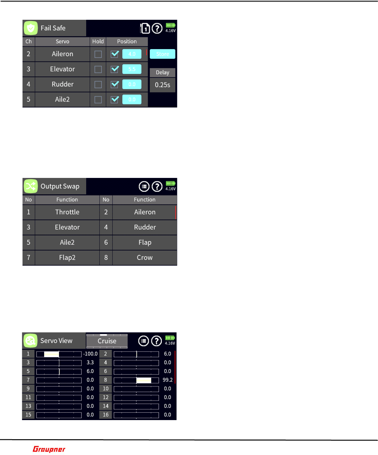
FAIL SAFE
In the Fail-Safe menu, you can setup the positions of
your flight controls in case the receivers lose contact
with the radio.
Next to each channel there is the option to set the
failsafe as follows:
Hold – will hold the current control position.
Position – will revert to the value as set in the blue
position field. To set the value for the control, check
the checkbox to activate the position option, move the
control to the desired position and tap on the blue field
to record that value.
Store – tapping on store will record and store all the settings in the active receiver (receiver
needs to be turned on and bound to the current model).
Delay – determines how fast the receiver will revert to the failsafe values when
communication is lost.
Tapping on the page icon next to the help icon provides access to the digital channels.
B11S1
OUTPUT SWAP
The Output Swap enables you to swap the default
output channels with another channel.
This assignment can be changed manually, or it can be
assigned to outputs in which the channel designation
(x) was not changed.
To change a channel output, tap on the channel you
would like to swap with another channel, which opens
the function selection menu. Tap on the channel you
want the channel to be swapped with. For example,
when you want to move channel 2 (aileron) to channel
8, tap on channel 8 and on the selection menu tap on
channel 2 (aileron).
You can also delete a channel assignment by tapping on the delete field in the selection
menu.
You can assign the channel outputs automatically by tapping the Auto Assign field in the
top menu icon next to the help icon.
B12S1
SERVO VIEW
The Servo View menu shows the present positions of
the radio controls such as sticks, levers, knobs and
switches.
The default view is for the first 16 channels. Viewing
additional channels (depending on radio model) can be
done by pressing the arrow keys (top 2 keys left of
screen) or by swiping the screen up or down.
Tapping on the screen will toggle to a detail view with
the channel names and numerical representations of
each channel position in microseconds. A value of 1500
µs represents 0% which is a control middle/neutral
position.
Tapping on the menu icon next to the help icon brings up the servo testing input bar.
Graupner mz-32 / mz-16 Help Reference Manual
Page 17 of 44 Help-Ref-EN-V1.1
When the delay checkbox is tagged, servo movements will be delayed with the delay as
specified in the delay field. You can delay servo movements between 0.5 and 3 seconds.
To start servo testing, tap on the start field.
To activate a channel to be tested, tap on the channel number to highlight it in blue.
B14S1
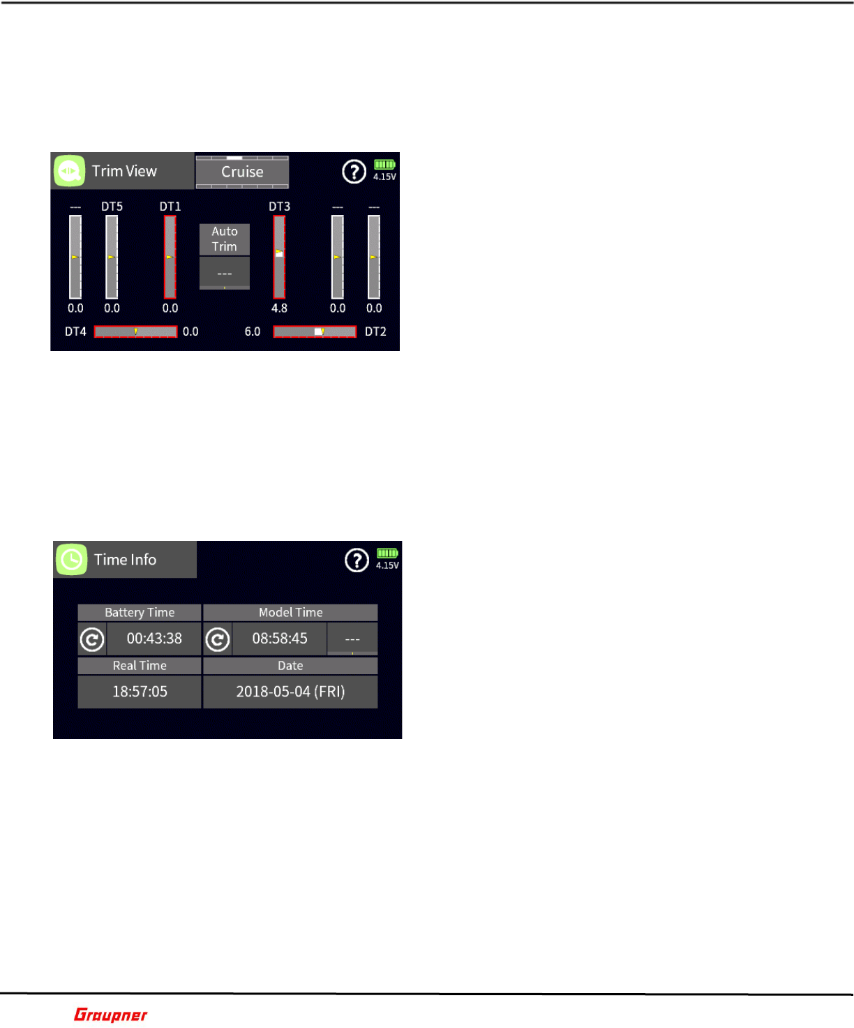
TRIM VIEW
The Trim View shows the current position of any
assigned and active digital trim (DT).
The trim view menu can be accessed from the Base
Menu or briefly by moving a trim control of the
transmitter.
The Auto Trim function assists with setting up trim
positions during the initial operation of a model. The
function only works on the aileron, elevator and rudder
channels and is activated by a switch during model
operation.
To assign a switch to the Auto Trim function tap on the
--- field and select a control which should be preferably a momentary control.
To trim your model bring it into the desired attitude with the active controls and activate
the switch at the same time. Release the controls within 1 second.
The trims will be set to match your previous control inputs automatically with a maximum
possible trim deflection of 30%.
It is recommended to de-activate the auto trim function by removing the assigned control
to prevent accidental operation.
B15S1
TIME INFO
You can view and set the radio time and date as well
as view the total battery time since the radio was
charged.
Battery Time – shows the total battery time since the
last charge. Tapping on the reset icon will reset the
time back to zero.
Model Time – shows the total time the model has been
loaded and active on the radio. You can set up a switch
to reset the model time value or tap on the reset icon.
Tapping on the real time or date fields allows you to
set the time and date on the radio.
B16S1
Graupner mz-32 / mz-16 Help Reference Manual
Page 18 of 44 Help-Ref-EN-V1.1
FUNCTION Menu
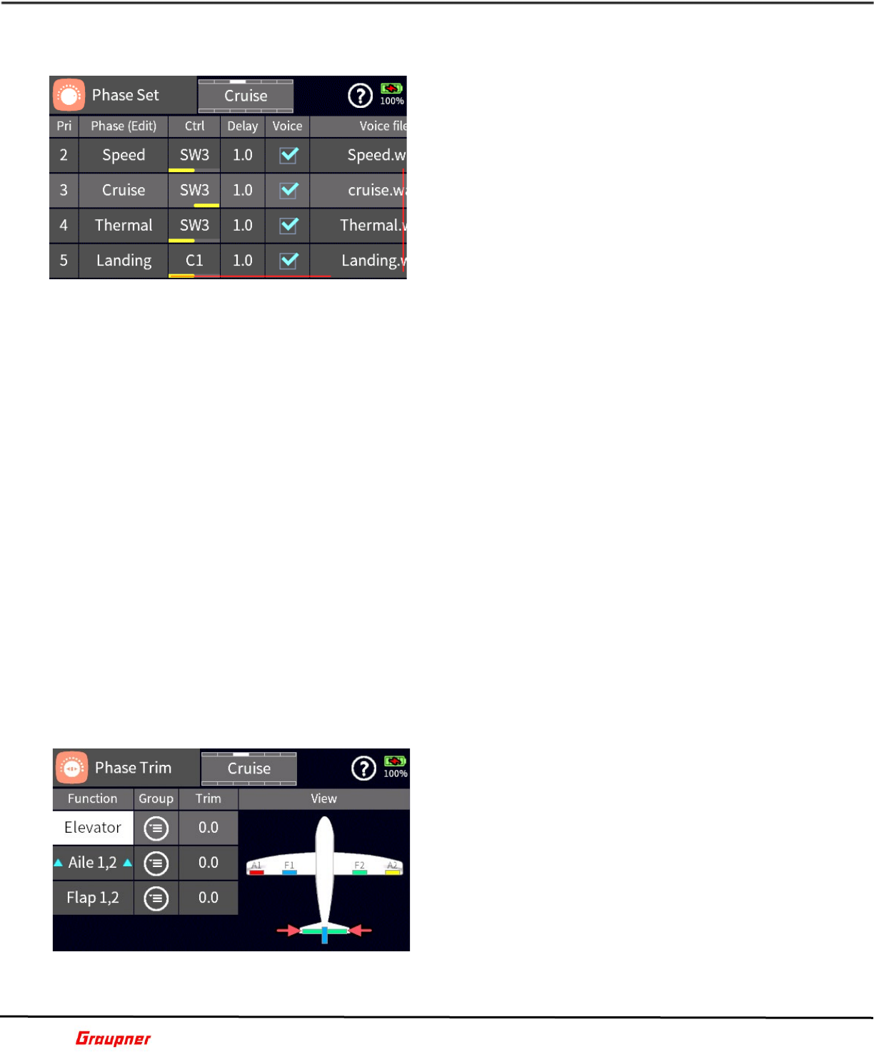
PHASE SET
With phases you can create selectable custom settings
for specific needs/configurations while operating your
model.
A Phase with the higher number, as displayed in the Pri
column, has priority over a lower numbered Phase.
Tap Add a Phase by tapping on the number left of the
phase name. The edit toolbar will be displayed.
Tap on the plus sign to add a phase. You can select
from a list of pre-set phase names or chose the blank
(---) which can be renamed later.
Tap on the trash can icon to delete the phase.
Tap on the document icon to copy the Phase settings to another Phase.
Select a Phase by tapping on the Phase number and then use the Up/Down arrows to
change the Phase priority.
Tap on the circle arrow icon to reset the Phase to the default settings.
Tap on the pencil icon to edit the Phase name.
In the Ctrl column you can assign a switch (Input Control) to activate the Phase.
The Delay setting determines how long it will take until the Phase takes full effect. The
change will happen gradually, determined by the Delay setting.
The Voice checkbox enables a voice announcement when the Phase is activated. You can
keep the default voice file or select your own from the available voice files.
Tap on the Voice file name to select a new or change the existing voice file. If a voice file
was already assigned, the name is highlighted. To change to a different voice file, tap the
X in the upper right corner to deselect the current voice file. Select a new voice file by
tapping first on the file name and then on the check mark icon (upper right corner) to
activate your selection. Tap on the exit icon (closing door in upper right corner) to return
to the Phase Set menu.
You can test/listen to the selected phase announcement by tapping on the Play icon.
If you do not wish to have the motor active during a phase, tap the Motor checkbox which
will deactivate the motor for the phase. For example, this can be used by sailplane pilots
during landing approach, when the sailplane is in a butterfly configuration.
F01S1
PHASE TRIM
The Phase Trim settings enables you to have different
control surface deflections for each flight phase. For
example, sailplane pilots can set their camber settings
for each control surface or jet pilots can add aileron up
deflections to reduce speed during landing.
The control surfaces available for selection in the
Function column depends on your Model Type settings.
Select a control surface by tapping on the
corresponding field in the Function column. You will
notice that the selected control surface is indicated by
the red arrows in the View image.
Phase trims are set by default as flight phase
dependent in the Group column. Tapping on the group icon will toggle between the global
and phase-dependent setting.
Graupner mz-32 / mz-16 Help Reference Manual
Page 19 of 44 Help-Ref-EN-V1.1
Tapping on the Trim field for a control surface will activate the edit toolbar where the trim
value for each phase can be assigned. Make sure you have the phase active for which you
want to enter a new value.
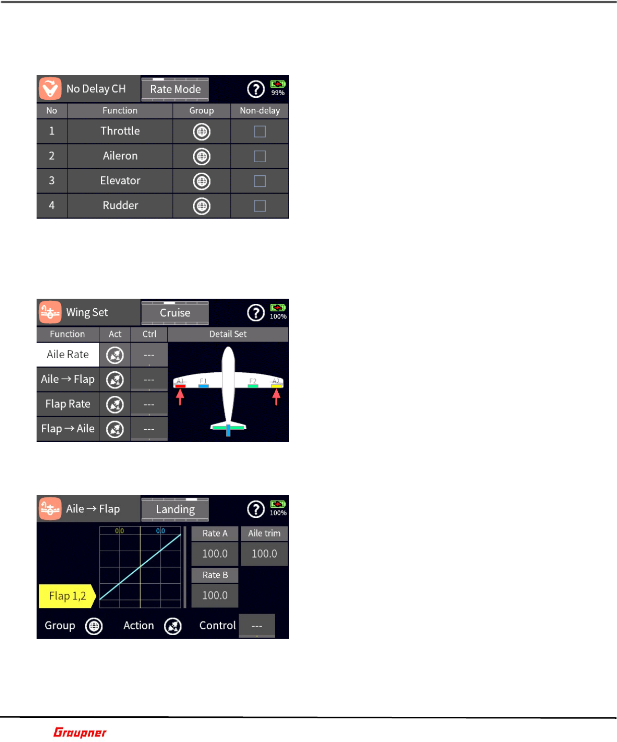
NO DELAY CH
In the No Delay Channel menu, you can exclude
channels from being affected by a previously set delay
during phase switching.
For example, you may have a phase where the ailerons
and flaps have a certain offset and to ensure a smooth
transition the phase has a delay setting. However, you
may want the ailerons to be excluded from the delay
when a specific phase is activated.
The channel number is displayed in the No column. The
Function column displays the channel name.
Tapping the Group icon for the respective channel
permits to toggle between the global and phase-dependent setting.
Tap on the Non-delay checkbox to select a channel (check mark) for the exclusion of a
previously assigned delay for the active flight phase (displayed in top center of screen).
F03S1
WING SET
In the Wing Set menu you can activate and deactivate
various mixes between the wing control surfaces, set
rates for control surface deflections and the sensitivity
of trims.
The Function column lists the name of available control
surface mixers and control surfaces. Tapping on a
Function field will graphically highlight (red arrows) the
affected channels on the Detail Set image.
Tap on the respective Act icon to activate or deactivate
a mix or control surface setting, .
You can assign a switch (Input Control) to activate a
mix or control surface setting by tapping on the respective Ctrl field.
F04S1
WING SET DETAIL
Tapping on the Detail Set image will provide additional
settings for control surface rate and trim sensitivity.
The available settings vary based on what
mixer/channel has been chosen.
In the Wing Set Detail menu you will set the rates for
each of the control surfaces that are part of the mix.
Each mix can be global or phase dependent. Tapping
the Group icon toggles between the global and phase-
dependent setting.
The mix can be activated by tapping on the Action icon
which will enable the mix for that phase. If the mix is
set as global the mix will be permanently active unless a control is assigned to turn the mix
on or off.
Note: The Act/Action icon and Ctrl assignment in this section is the same as in the main
Wing Set section.
Graupner mz-32 / mz-16 Help Reference Manual
Page 20 of 44 Help-Ref-EN-V1.1
You can assign a switch (Input control) to activate a mix or control surface setting by
tapping on the respective Ctrl field.
The values in the fields Rate A and Rate B will determine the amount of deflection for the
control surface in the mix.
To change the value, tap on the Rate A or Rate B field to activate the edit toolbar. Use the
slider control bar for large value changes or the arrow keys for changes in small steps.
Tapping on the chain link icon will link Rate A and Rate B for the simultaneous change of
the values.
The trim field allows you to set the sensitivity of the trim when the mix is active. The default
value of 100 provides normal trim control while a value of 50 will reduce its sensitivity by
50%.
F04S2
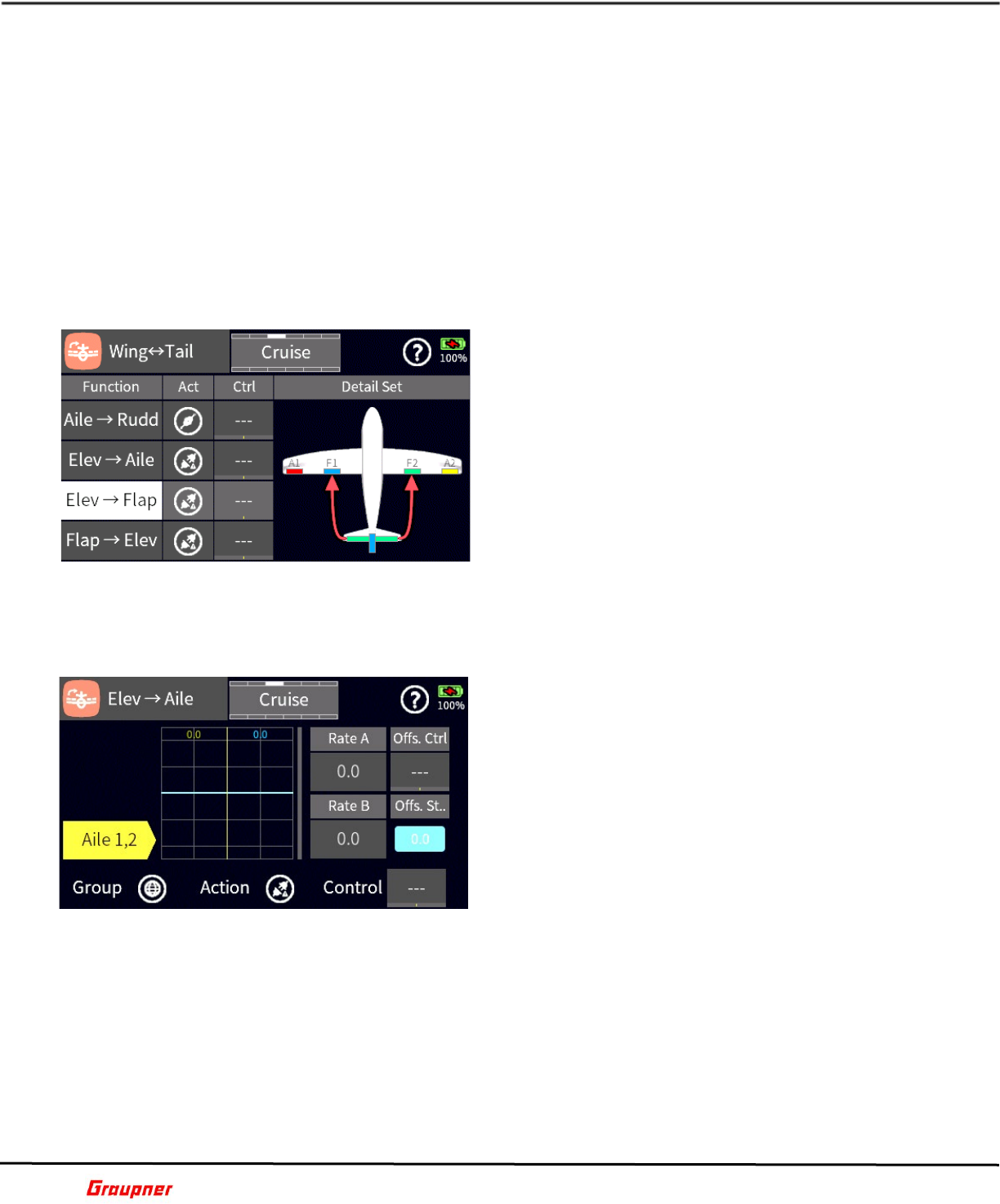
WING TAIL
In the Wing Tail menu you can activate and deactivate
various mixers between the wing and the stabilizer, set
mixing rates and assign switches (Input Control).
For example, use the Flap to Elevator mix to
compensate for pitch changes during the deployment
of flaps, the Elevator to Ailerons and Elevator to Flaps
for a Snap Flap setting.
The Function column lists the names of available
control surface mixers. Tapping on the mixer name
field (Function column) will highlight the affected
channels on the Detail Set image.
To activate or deactivate the mix, tap on the respective Act icon of a mixer.
You can assign a switch (Input Control) by tapping on the respective Ctrl field of a mixer.
F05S1
WING TAIL DETAIL
Tapping on the Detail Set image will provide additional
settings for rate, offset and offset switch (Input
Control). The available settings vary based on what
mixer has been selected.
In the Wing Tail Detail menu, you will set the rates for
the control surfaces that are part of the mix.
Each mix can be global or phase dependent. Tapping
the Group icon toggles between the global or phase-
dependent setting.
The mix can be activated by tapping on the Action icon
which will enable the mix for that phase. If the mix is
set as global the mix will be permanently active unless a control is assigned to turn the mix
on or off. Note: The Act/Action icon and Ctrl assignment in this section is the same as in
the main Wing Tail section.
You can assign a switch (Input Control) to activate a mix or control surface setting by
tapping on the respective Ctrl field.
The values in the fields Rate A and Rate B will determine the amount of deflection for the
control surface in the mix.
To change the value, tap on the Rate A or Rate B field, this will activate the edit toolbar.
Use the slider control bar for large value changes or the arrow keys for changes in small
steps.
Graupner mz-32 / mz-16 Help Reference Manual
Page 21 of 44 Help-Ref-EN-V1.1
Tapping on the chain link icon will link Rate A and Rate B for the simultaneous change of
the values.
You can set a fixed offset for the Elevator/Flap and Elevator/Aileron mixes that will deflect
the control surface the moment the elevator has reached the offset position.
To set an offset, move the Elevator control to the desired position and tap on the blue Offs.
St. field, which will store the position. Deflection of the control surface for example flaps
will only occur when the elevator has reached the previously set offset position.
You can assign a switch (Input Control) for Offs. Ctrl. by tapping on the Ctrl field.
F05S2
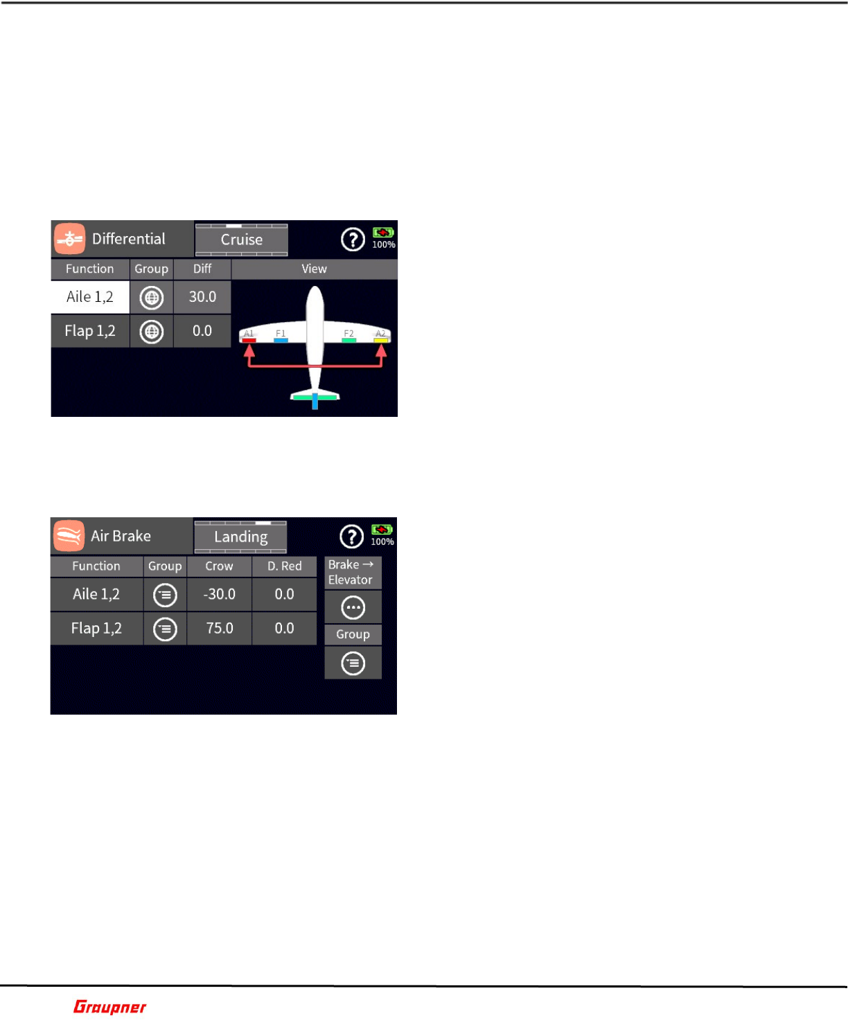
DIFFERENTIAL
In the Differential menu, you can reduce the downward
movement of a control surface to minimize adverse
yaw when an airplane is in a banked turn.
The Function column lists the names of control surfaces
that can be selected to set a differential value.
Tapping on a Function field will highlight (red arrows)
the affected control surfaces on the View image.
Differential settings can be global or phase dependent.
Tapping the Group icon toggles between the global or
phase-dependent setting.
To enter a value, tap on the Diff field, this will activate
the edit toolbar. Use the slider control bar for large value changes or the arrow keys for
changes in small steps.
F06S1
AIR BRAKE
In the Air Brake menu, you set the deflection of control
surfaces to reduce airspeed. Sailplane pilots will use
this menu to setup their crow or butterfly configuration
for the landing phase.
The Air Brake menu is inactive when the motor option
is checked in the Phase Set menu.
The Function column lists the name of control surfaces
which are available.
Air Brake settings can be global or phase dependent.
Tapping the Group icon toggles between the global or
phase-dependent setting.
The level of positive or negative deflection is set in the crow column. Tapping on the Crow
field will activate the edit toolbar.
The differential reduction D. Red field determines by how much a control surface differential
should be reduced when the air brake mode (Phase) is active.
Correcting attitude (pitch) changes when the mix is active can be configured in the Brake
Elevator section.
F07S1
Graupner mz-32 / mz-16 Help Reference Manual
Page 22 of 44 Help-Ref-EN-V1.1
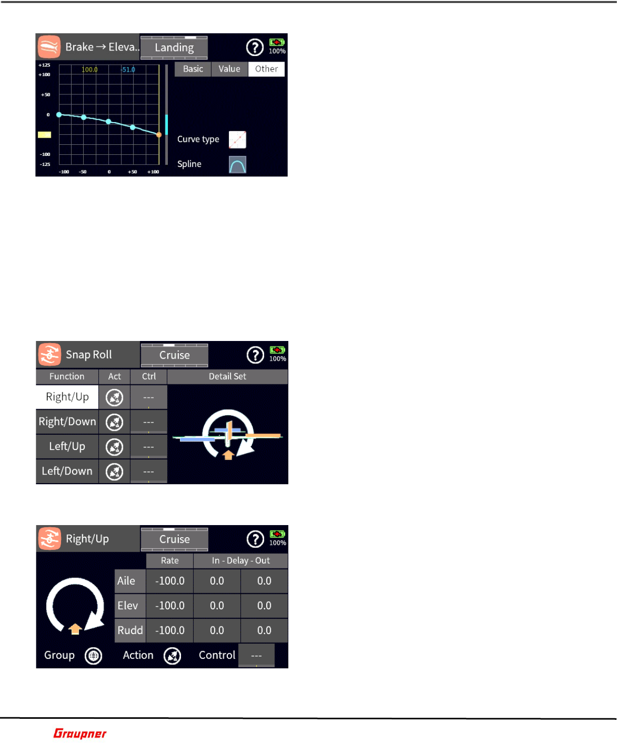
AIR BRAKE DETAIL
Attitude (pitch) changes due to control surface
deflections may need to be compensated with a positive
or negative elevator deflection.
Tap on the Other menu selection (detail section) to
gain access to the Curve type setting. Tap on the Curve
type icon to select single point or multi point curves.
Tapping on the Spline icon will set a linear or nonlinear
curve fitting between the individual points on the curve.
Tap on the Value menu selection to set the x and Y
values for your curve. The points on an axis can also
be adjusted by moving the orange marker of the
respective axis. Simply tap and hold down on the marker to move it.
If you selected a multi-point curve you can add additional curve points by positioning the
brake cursor line at the desired location on the curve and press the plus (+) icon. Individual
points can be selected for adjustment by moving the brake cursor line on top of the point
or by tapping on the point (point will change color).
Tap on the Basic menu selection to select an overlay channel. It will visually overlay the
selected channel over the current channel for comparison.
Tapping on the Group icon will toggle the group setting between global and phase
dependent.
F07S2
SNAP ROLL
Use Snap Roll menu to preset 4 different snap roll types
which can be activated during flight with a switch
(Input Control).
To select a specific type of snap roll, tap on the
respective Function field. The Detail Set image will
change according to the selected type of snap roll.
Tap on the Act icon to activate the snap roll or assign
a switch (Input Control) by tapping on the Ctrl field,
which will activate the Select Input Control screen.
Tap on the Detail Set image to access the detail
settings for the selected snap roll.
F08S1
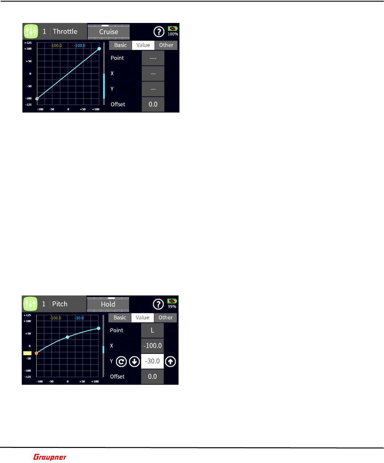
SNAP ROLL DETAIL
This menu is used to set the desired control surface
Rate as well as the delay times for each control surface.
Tapping on the Rate field will activate the edit toolbar.
Set the desired control surface deflection when the
Snap Roll is activated.
Tap on the In – Delay – Out fields to set the time it
will take for the control surface to gradually reach its
set position.
Tapping on the Group icon will toggle the Group setting
between global and phase dependent.
F08S2
Graupner mz-32 / mz-16 Help Reference Manual
Page 23 of 44 Help-Ref-EN-V1.1
THROTTLE CURVE
Note: The same settings can be accessed by selecting
Base – Control Set and tapping on Throttle Detail.
Changes can be made in either section.
The Throttle Curve settings allow you to create a
throttle behavior based on your preferences. The
default setting is linear (dual point), the channel output
increases/decreases by equal amounts over the entire
range
Tap on the Other menu selection to select a Curve type
and Spline behavior.
Tap on the Value menu selection to make changes to
curve settings. A flat (horizontal) curve can only have
its Offset / Y axes value changed. A dual point curve can have its Offset and both Y axes (L
and H) values changed. The changes occur in reference to the zero/midpoint of the curve.
A multi-point curve, permit changes for each individual point. Select a point by moving the
throttle cursor over a point (color changes) and use the X or Y arrow keys (left, right, up,
down icon) to change the point values. Add additional curve points by positioning the cursor
line at the desired location on the curve and press the plus (+) icon.
A selected point on an axis can also be adjusted by moving the orange marker of the
respective axis. Simply tap and hold down on the marker to move it, use the arrow keys
for fine adjustments.
To remove a curve point, select the point by moving the cursor over the point or tap on the
point (point will change color), then tap on the minus icon next to the Point number field.
Tapping on the Group icon in the Basic section will toggle the Group setting between global
and phase dependent.
Tap on the Overlay Ch. Field in the Basic section to select an overlay channel. It will visually
overlay the selected channel over the current channel for comparison.
When the active Model Type is set as Helicopter an additional horizontal line will show which
marks the relative position of the throttle limiter which is controlled on channel 12. The
throttle limiter is part of the model setup can be activated from the Throttle Limit option.
F09S1
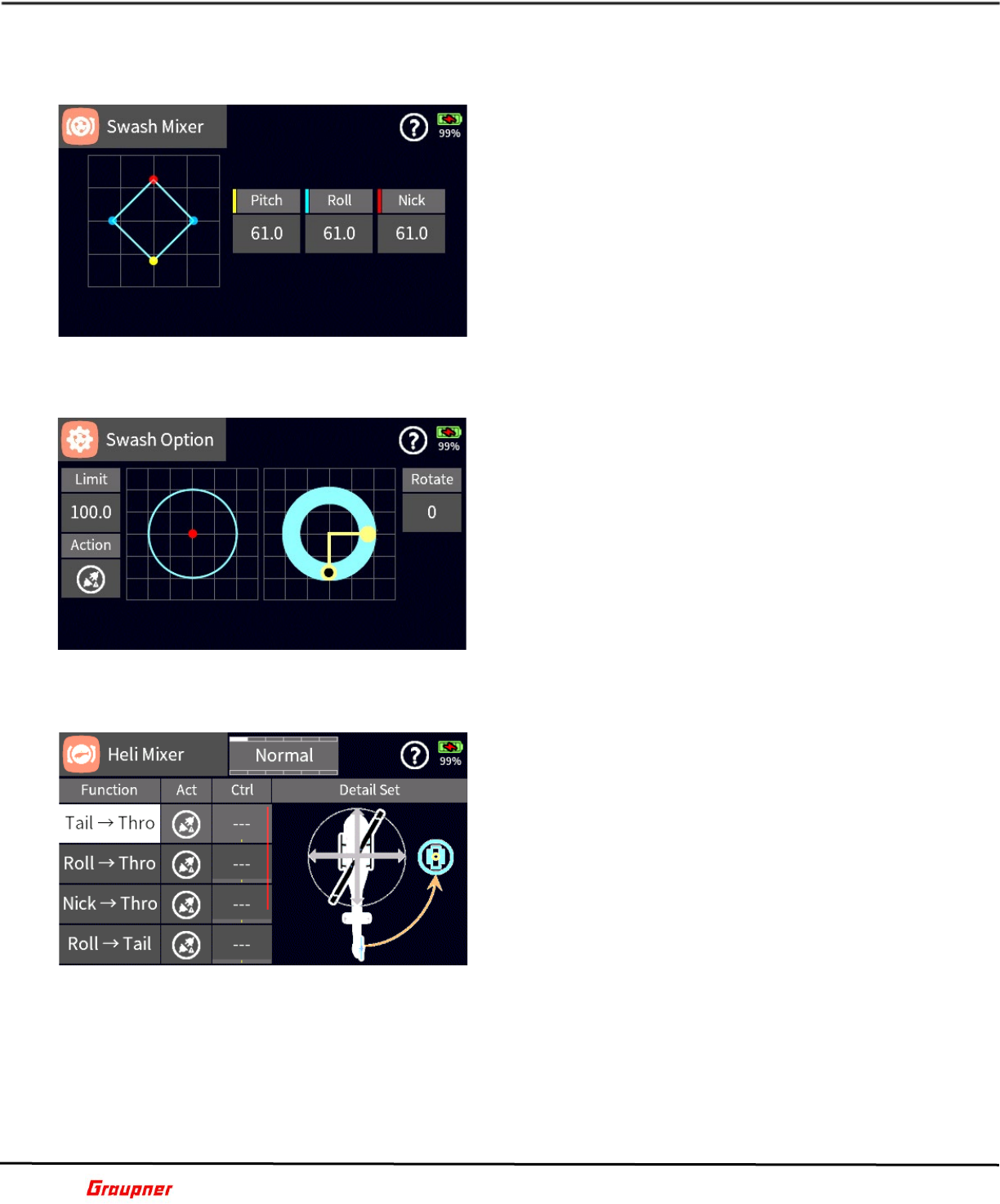
PITCH CURVE
In the Pitch Curve menu, you can set the behavior of
your swash plate for a specific flight mode.
Tap on the Other tab to select a curve and spline type.
Tap on the Value tab to make changes to the curve. A
flat curve can only have its offset or Y axes changed
while a dual point curve can have its offset and Y axes
changed along the zero midpoint of the curve.
When selecting a multi-point curve, you can change a
point by moving the throttle cursor over a point and use
the X or Y arrow keys to change the point values. You
can also tap on the orange guide tabs on the side to
roughly move the point to a desired position and further fine tune the values with the arrow
keys.
To add a curve point, move the cursor along the curve line to the desired location and tap
on the plus sign next to the Point field to add the additional point.
To remove a curve point, move the cursor over the point that needs to be removed and tap
on the minus sign next to the Point field to remove the point.
Graupner mz-32 / mz-16 Help Reference Manual
Page 24 of 44 Help-Ref-EN-V1.1
On the Basic tab you can set the curve to be global or flight phase dependent.
F10S1
SWASH MIXER
In the Swashplate Mixer menu, you can adjust the
mixing ratios for pitch, roll and nick.
This may be necessary when the swashplate type
needs additional adjustments.
For example, if a 140-degree swashplate has been
selected in the model type menu but the helicopter has
a 135-degree swashplate the mixing ratios can be
adjusted to ensure proper swash operation.
F11S1
SWASH OPTION
In the Swash Option menu, you can set up the swash
travel limits to eliminate servo binding and blade
rotation
Tap on the Limit field to bring up the edit toolbar to
make and use the slider or arrow keys to make value
changes.
To activate the Swash Option tap on the Action icon.
Tap on the rotate field to adjust your blade rotation
(phasing) for multi blade helicopters.
F12S1
HELI MIXER
In the Heli Mixer menu, you will find a variety of mixers
that when activated can assist during flight.
Tap on the function menu mix field to select the desired
mix. The Detail Set menu will graphically show how the
mix will be applied.
The Act column activates or de-activates the mix. If
you want to enable the mix with a control tap on the
Ctrl column to bring up the input control dialog to
assign the control.
Tapping on the Detail Set icon will bring you to the Heli
Mixer detail menu.
F13S1
Graupner mz-32 / mz-16 Help Reference Manual
Page 25 of 44 Help-Ref-EN-V1.1
HELI MIXER DETAIL
In the Heli Mixer Detail menu, you can set the values
for the active mix.
The values in the fields Rate A and Rate B will
determine the amount of deflection for the active
channel in the mix.
To change the value of the mix, tap on the Rate A or
Rate B field to bring up the edit toolbar. You can use
the control bar for fast value entry or the arrow keys
for smoother entry input.
Tapping on the keychain icon will link both Rate A and
Rate B and control their values simultaneously.
Tap on the reset icon to undo the current values to bring them back to default.
Tap on the Group icon to set the mix as global or flight phase dependent.
The Act column activates or de-activates the mix. If you want to enable the mix with a
control tap on the Ctrl column to bring up the input control dialog to assign the control.
F13S2
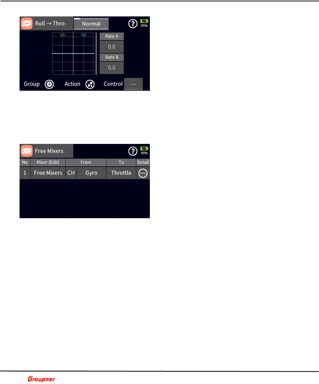
FREE MIXERS
There are in total 16 available mixers available.
You can select from 3 different Curve types, 2 different
Spline types and 3 different Link types. A mixer can be
configured to be from a channel (master) to another
channel (slave) or from a switch (Input Control) to a
channel (slave).
Add a Free Mixer by tapping on the number in the No
column.
The edit toolbar will be displayed.
Tap on the + icon to add a mixer.
Tap on the name of the mixer in the Mixer (edit) column to edit the mixer name.
The edit toolbar will be displayed.
Tap on the edit icon (pencil) to edit the mixer name. The edit toolbar has also options to
delete (trash can) a mixer and change its sorting order (up and down arrow icons).
Tap on enter icon (check mark) to complete the changes.
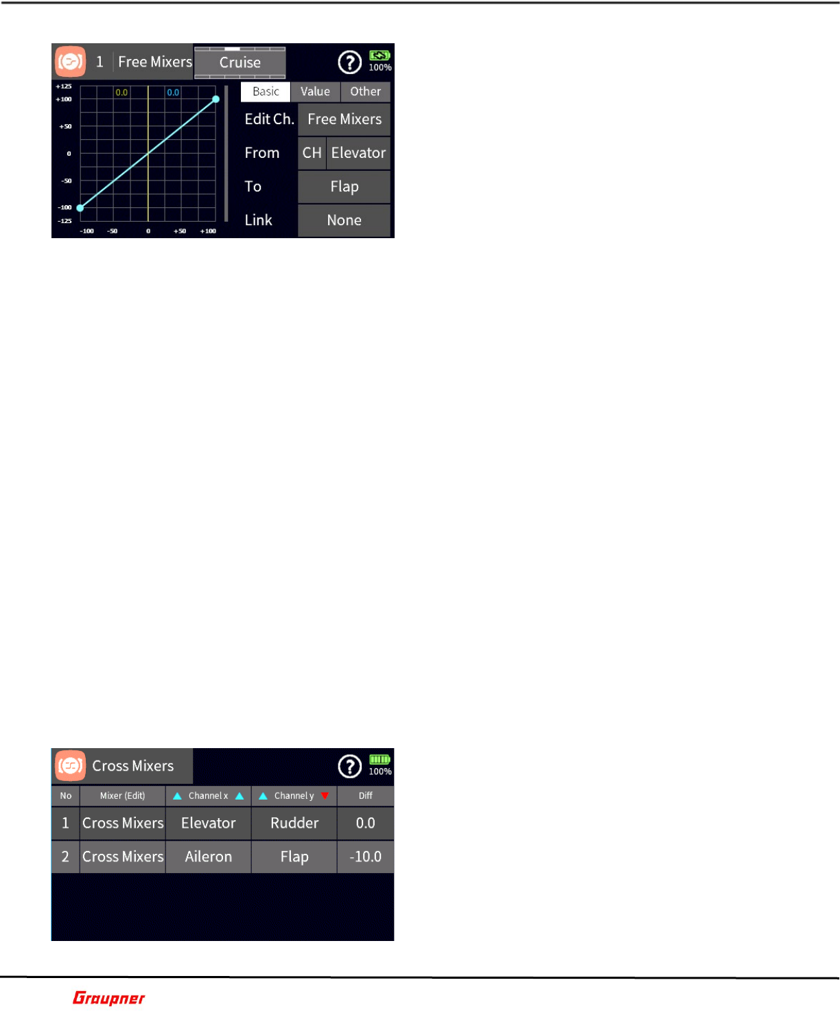
Tap on the From field to select either the master channel or switch (Input Control).
Tapping on the field right of the mixer name field will toggle the setting between channel
(CH) and switch (SW).
The default is CH (channel). Selecting SW (control) will display the Select Input Control
dialog when tapping on the From field.
Tap on the To field to select the slave channel for the mixer.
Tap on the Detail icon to activate the mixer detail section.
F14S1
Graupner mz-32 / mz-16 Help Reference Manual
Page 26 of 44 Help-Ref-EN-V1.1
FREE MIXERS DETAIL
Tap on the Other menu selection to set the basic values
for the mixer.
Tapping on the Group icon will toggle the Group setting
between global and phase dependent.
Tapping on the Action icon will activate or de-activate
the mixer or assign a switch (Input Control) by tapping
on the Control field, which will activate the Select Input
Control screen.
Tap on the Curve type icon to create a mixer behavior
based on your preferences.
The default setting is linear (dual point); the channel
output increases/decreases by equal amounts over the entire range.
Tapping on the Spline icon will set a linear or nonlinear curve fitting between the individual
points on the curve.
Tap on the Value menu to make changes to curve settings.
A flat (horizontal) curve can only have its Offset / Y axes value changed.
A dual point curve can have its Offset and both Y axes (L and H) values changed. The
changes occur in reference to the zero/midpoint of the curve.
A multi-point curve permits changes for each individual point. Select a point by moving the
cursor over a point (color changes) and use the X or Y arrow keys (left, right, up, down
icon) to change the point values.
Add additional curve points by positioning the cursor line at the desired location on the
curve and press the plus (+) icon.
A selected point on an axis can also be adjusted by moving the orange marker of the
respective axis. Simply tap and hold down on the marker to move it, use the arrow keys
for fine adjustments.
To remove a curve point, select the point by moving the cursor over the point or tap on the
point (point will change color), then tap on the minus icon next to the Point number field.
Tap on the Basic menu selection to review or change the mixer settings.
Tap on the Link field to specify how the mixed channels will be linked.
None
Link
After Mix
After Mix with Trim
F14S2
CROSS MIXERS
The Dual Mixer menu provides settings for bi-direction
mixers.
It is basically a cross mixer like in a V-Tail setup. The
assigned Master channel will cause the same
directional control surface movement on the Slave
channel. However, the Slave channel will have the
opposite/reverse control surface movement on the
master channel.
Tap on the + icon in the No column to add the first
mixer.
Tap on the number in No column to activate the edit
toolbar.
Graupner mz-32 / mz-16 Help Reference Manual
Page 27 of 44 Help-Ref-EN-V1.1
Tap on the edit icon (pencil) to edit the mixer name.
The edit toolbar has also options to delete (trash can) a mixer and change its sorting order
(up and down arrow icons).
Tap on enter icon (check mark) to complete the changes.
Tapping on the Master or Slave field will activate the channel selection dialog.
Tap on the Diff field to set the differentiation value (reduced deflection of control surfaces
by Master channel) between the two outputs.
F15S1
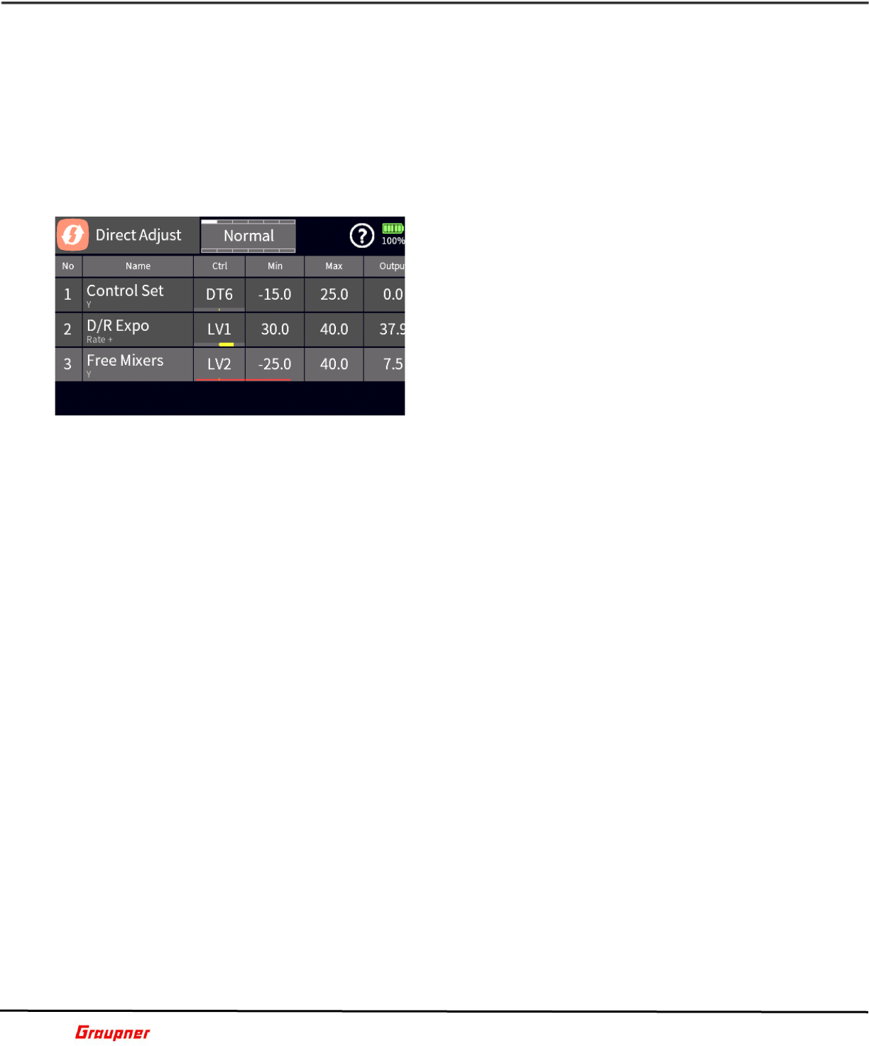
DIRECT ADJUST
The Direct Adjust function provides you with the
additional flexibility to further influence or change most
settings and data points, like in a curve. One of the
many applications mighty be the inflight adjustment of
a user created or standard mixer. Using the Direct
Adjust function requires a secondary control that
influences the mix, such as rudder to elevator when
flying a knife edge to reduce control coupling.
Direct Adjust is available with many of the standard
radio functions, such as dual rates. Here you can fine
tune the rates or expos.
Unlike the typical radio functions, a new Control Adjust needs to be added from within the
section you wish to influence. In other words, Direct Adjust is not added directly via the
Function menu, they are listed there for further fine tuning. Direct Adjust gets initially
activated within the section you wish to influence. The availability of Direct Adjust can be
easily recognized by the presence of the Direct Adjust icon, which is a square with a red
rectangular in the upper right corner. Hint, make sure that only a single data point is
selected in a graph, otherwise Direct Adjust will be unavailable (grayed out).
EXAMPLE
In the Free Mixer Function, select a rudder to elevator mix with a multi-point curve. Next
you would like to influence the curve behavior at point 4. Assign a Direct Adjust control to
curve point 4 by moving the vertical cursor with your rudder stick over curve point 4 until
it turns orange and then tap on the Direct Adjust icon while the data point 4 is orange.
Another way to select curve point 4 is to simply tap on it, which will turn it orange, then
tap on the Direct Adjust icon.
The control bar on the bottom of the screen will appear; this is where you can set or reset
the X and Y values. Select the axes you want to control by tapping on the respective field.
Tap on the Direct Adjust icon, which will activate the Direct Adjust Function menu.
The Name field shows the originating mix which in this example is Free Mixers and the axes
controlled by the Direct Adjust function which is the Y axes.
The Ctrl field is used to assign a control that is used to change the curve point. You can use
any control type, in this example the digital trim DT5 is used.
The Min/Max fields specifies the Min and Max values of curve point movement to avoid
potential over control of the mix.
The Output field shows the current output value and position of the adjusted curve point.
This can be used later as the reference for changing the curve point from adjustable to a
fixed offset.
Checking the Sound box will activate an audible voice announcement of the current output
value each time the Direct Adjust control is used (in this example DT5).
Tapping on the Voice field will provide you with the option to select a voice file which is
associated with the Direct Adjust for easier reference during operations.
Graupner mz-32 / mz-16 Help Reference Manual
Page 28 of 44 Help-Ref-EN-V1.1
The Play button allows you to sample the selected voice file.
F20S1
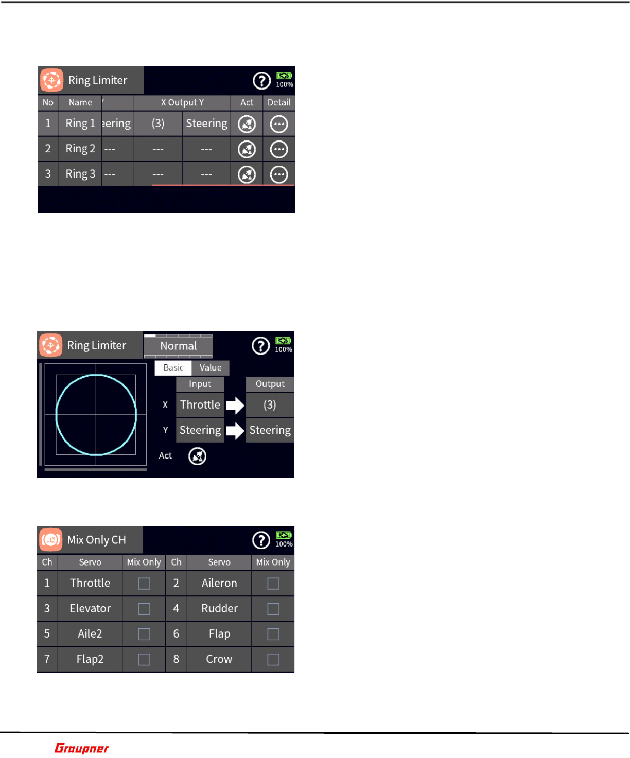
RING LIMITER
A ring limiter ensures that when using a cycloidal drive
such as a Voith-Schneider drive, the servos do not run
into the limit when the control sticks are moved into
the corners.
There are a total of three ring limiters available.
In the No column, the number of the ring limiter is
listed.
In the Name column, the name of the ring delimiter is
shown.
In the columns X input Y, the axes for the input X and
input Y are assigned by tapping on the field where you
can select the corresponding input.
In the columns X output Y, the axes for the output X and output Y are assigned by tapping
on the field where you can select the corresponding input.
Tapping on the Act icon determines if the limiter mix is activated or deactivated.
Tap on the detail icon to enter the Ring Limiter Detail menu.
F16S1
RING LIMITER DETAIL
In the Ring Limiter Detail menu, you can set the mix
values.
Tap on the Value menu to set the values that will adjust
the size and the shape of the ring
F16S2
MIX ONLY CHANNEL
The Mix Only channel menu allows you to designate a
virtual channel that is used only for controlling a mix,
without losing the channel for output.
For example, if you assign a switch (Input Control) to
channel 8, as the master for enabling a mixer input.
Setting channel 8 as Mix Only will only use the switch
(Input Control) assigned to channel 8 without sending
an output signal to CH8. Therefore channel 8 is
available for other functions.
F17S1
Graupner mz-32 / mz-16 Help Reference Manual
Page 29 of 44 Help-Ref-EN-V1.1
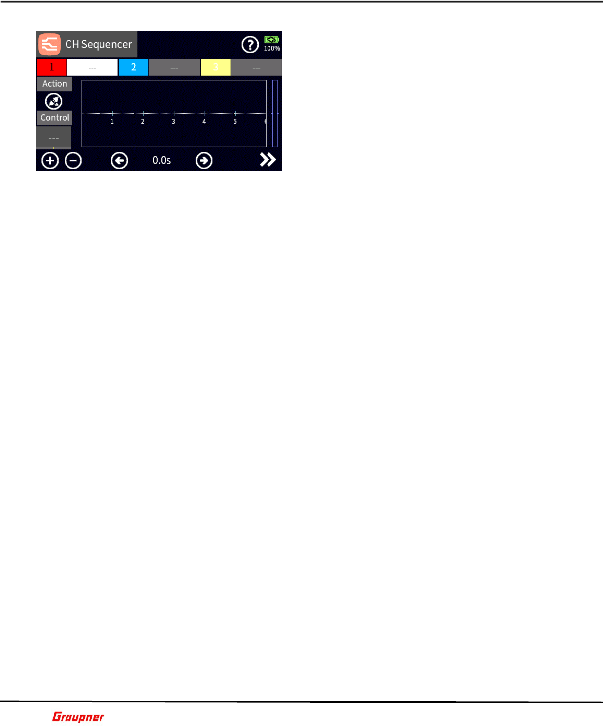
CHANNEL SEQUENCER
The Channel Sequencer can control up to 3 channel
outputs for functions such as opening and closing
multiple gear doors. Control landing operation and
even sequencing SLS power drives in sailplanes.
The uses for the channel sequencer are only limited by
your imagination.
Each channel can have its own switch (Input Control)
assigned for added flexibility or you can use the same
switch (Input Control) to initiate the programmed
sequence for all 3 channels.
Each channel has its own color. A channel is selected
by tapping on the channel number field which will highlight the channel.
Tap on the Action icon to activate the sequence for channel.
To start a programmed sequence, it is required to assign a switch (Input Control) by tapping
on the Control field which will display the Select Input Control dialog.
Tap on the plus sign to add a point on the time line.
Tap on the minus sign to remove the active highlighted point.
You can move between points by tapping on the dot (color will change) on the timeline or
by tapping on left/right arrow icons to move the vertical red cursor.
Tap on the right double arrow (chevron) icon, which will provide different options in the
bottom line.
Tap on the time value to activate the field for change. Use the left/right arrow keys to move
the currently active dot along the timeline axis.
Tap on the percent value to activate the field for change. Use the up/down arrow keys to
increase/decrease the currently active output value for the data point.
F18S1
Graupner mz-32 / mz-16 Help Reference Manual
Page 30 of 44 Help-Ref-EN-V1.1
SPECIAL Menu
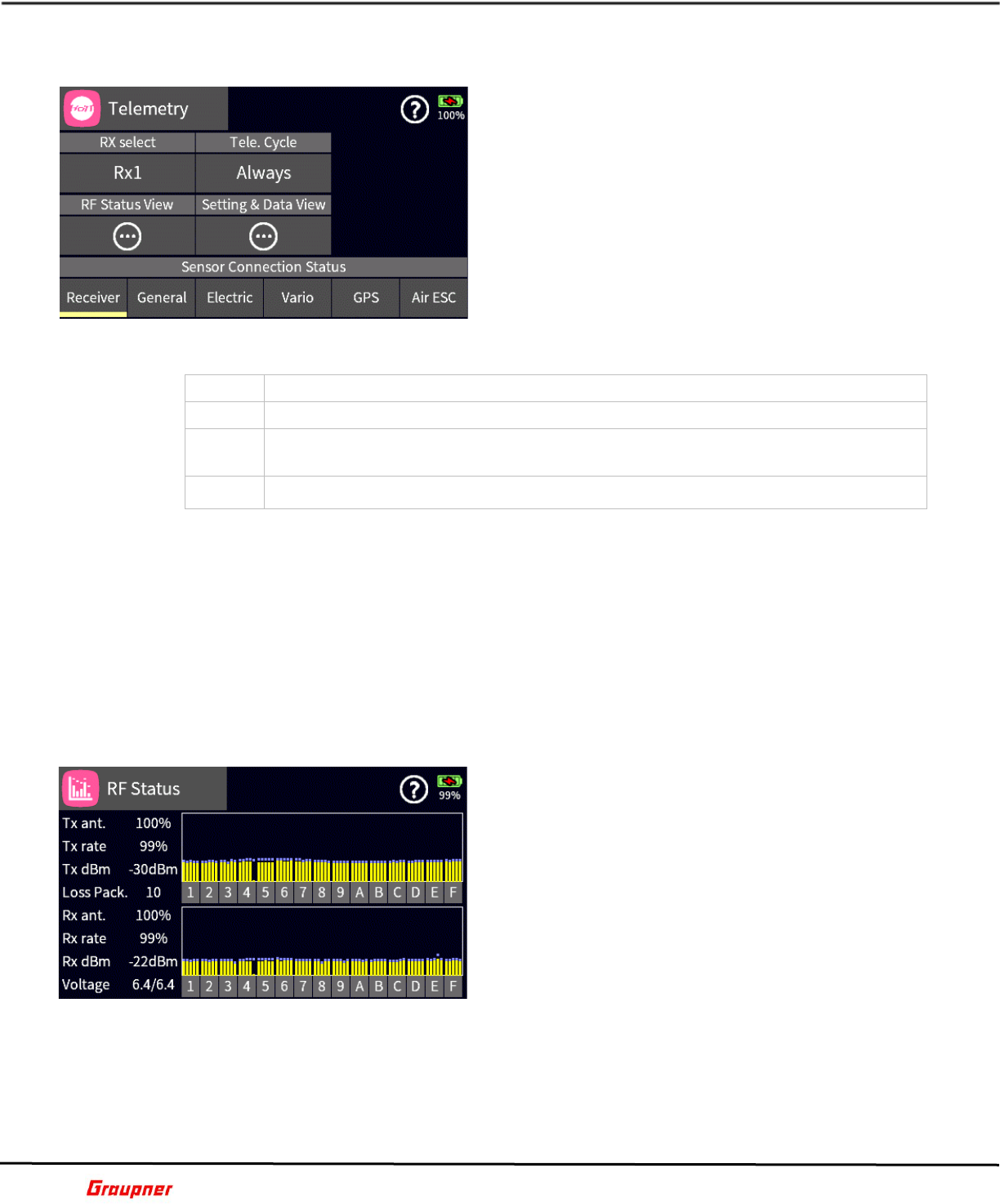
TELEMETRY
In the Telemetry menu you can access various
functions for viewing and setting up telemetry
functions. In case multiple receivers are bound to the
transmitter you will need to select the receiver which
will be used for the telemetry data. It is possible to
switch between receivers for telemetry data or turn Off
telemetry entirely.
Tap on the RX select field to select the receiver. The
selected receiver will be automatically designated as
the active telemetry receiver.
Telemetry Cycle
Tap on the Tele. Cycle field to set the frequency of telemetry data updates.
Value
Description
Always
The transmitter reacts normal to the back-channel of the selected receiver.
4x / 8x
The transmitter reacts to the back-channel of the selected receiver with the
chosen delay.
OFF
The transmitter telemetry functions are deactivated.
For example, in those situations where two model airplanes are operated at close proximity
and controlled by two separate transmitters, you may choose to reduce or eliminate the
transmission of data via the telemetry back channel for one of the models to avoid potential
interference. Situations that might cause such interference include drones that have a
separate transmitter for control and camera operations or airplanes that tow or carry other
airplanes. Experiment with the telemetry cycle to find the proper value for your situation.
Sensor Connection Status
Provides the lists of sensors and indicates with a green bar below the name which sensors
are detected.
S01S1
RF STATUS VIEW
Tap on the detail icon to view the RF status and quality
for each frequency channel. This display visualizes the
quality of the connection between transmitter and
receiver.
If there is no connection to a receiver, no data is
displayed in the 2 rectangular areas. Check, to make
sure your receiver is on or select the correct receiver.
Upper Rows
Signal level in dBm at the transmitter for channels 1 to
75 coming from the receiver (2.4 GHz band).
Lower rows
Signal level in dBm at the receiver for channels 1 to 75 coming from the transmitter (2.4
GHz band).Note
The height of the bar is a measure of the reception signal level expressed as logarithmic values
with the unit dBm (1mW = 0dBm).
0 dBm corresponds to the two baselines. Therefore, the level is poorer the higher the bar
and vice versa.
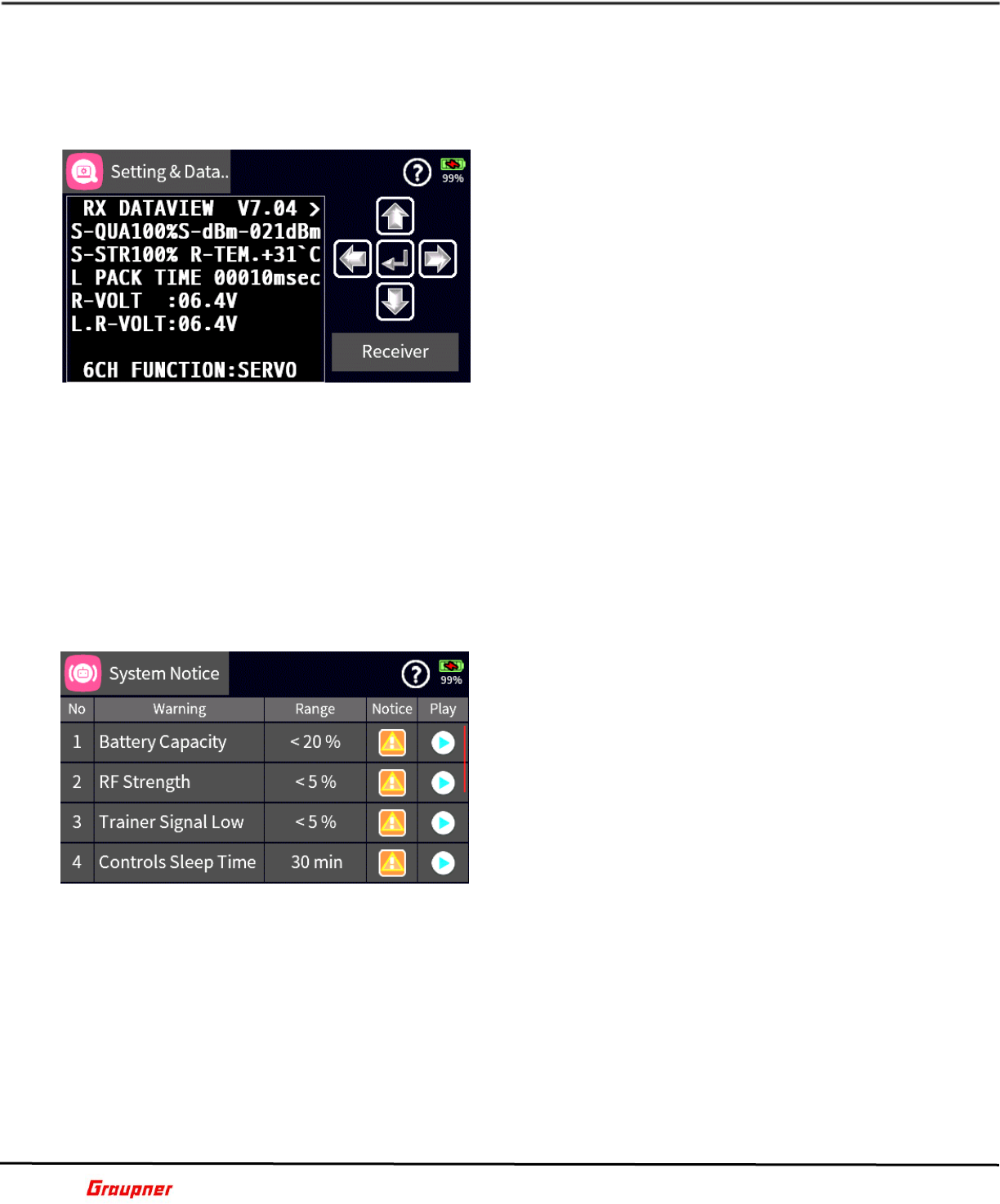
Graupner mz-32 / mz-16 Help Reference Manual
Page 31 of 44 Help-Ref-EN-V1.1
The dots above the bar mark the worst reception signal levels since the opening of the "RF
Status" display. Reset these data points by simply exiting and reentering this display.
Additional numeric information about the signal levels is provided on the left.
S01S2
SETTINGS AND DATA VIEW
Tap on the Setting & Data View Detail field, in case you
wish to view and/or change the settings which are
stored in a receiver or flight controller.
The display will switch to the ASCII interface to view
the settings or make changes. If there is no connection
to a receiver, no data is displayed.
You can also access the ASCII menu directly by
pressing the telemetry key on the transmitter front
panel (right side center key).
Select a different sensor, in case there more than one,
by tapping on the sensor field in the ASCII interface
(lower right corner of display).
A detailed description for settings of standard receivers such as the GR-12 or GR-16 can be
found in the respective receiver manual. Please note that receivers like the GR-12L, GR-
16L, GR24L and GR-32L are functionally identical.
Specialty receivers, such as the GR-18 HoTT (No. 33579 or S1019), are equipped with
separate versions of the "SETTING & DATA VIEW" menu. The descriptions of these special
settings are contained in the respective receiver manual.
Tap on the arrow icons to move between menus. Use the enter/select icon (check mark) to
select and change settings.
S01S3
SYSTEM NOTICE
Use the System Notice menu to configure System
notifications and warning messages during the
transmitter startup.
There are total of nine warning messages to select
from.
Select a Warning message by tapping on the message
number, which will open the edit tool bar. Tap on the
Up/Down arrow icons to change the message priority.
Tap on the Range field of a warning message to set its
trigger threshold. The edit tool bar will be activated.
Use the slider control bar for large value changes or
the arrow keys for single digit changes.
Tap on the Notice field of a warning message to activate or de-activate the available
notification types. A list of available notices will be displayed.
The Warning option will activate or de-activate the message. Vibration will activate or de-
activate the vibration (haptic) feedback. You can choose from 10 different vibration types.
Pre-Warning will activate or de-activate the Pre-Warning, which is the name of the warning
message.
Value will activate or de-activate a value announcement for the warning message, if
applicable.
Available notice settings vary depending on the warning message.
Tap on the Play button to test the notice, based on the current settings.
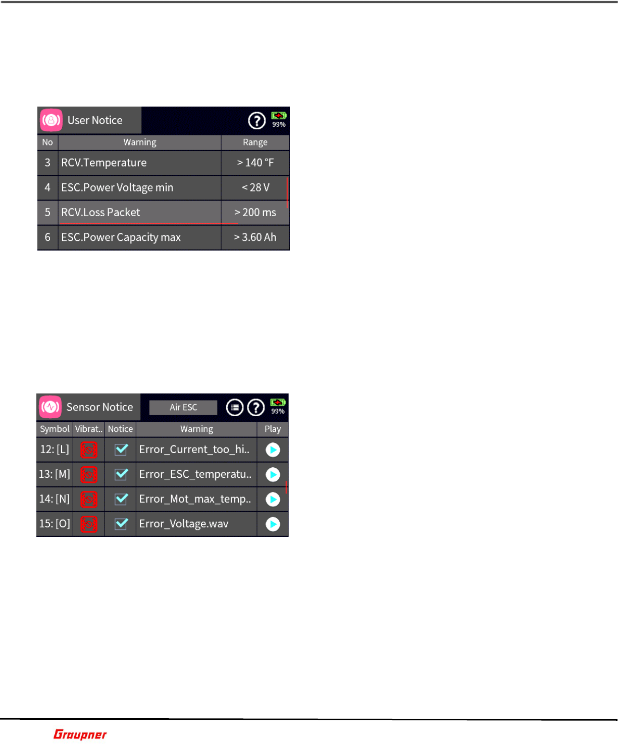
Graupner mz-32 / mz-16 Help Reference Manual
Page 32 of 44 Help-Ref-EN-V1.1
Notice No. 9 is activated by tapping on the blue Store field.
Place all your switches in the desired start positions before tapping on Store. When turning
on the transmitter you will be notified if a switch is not in its stored start position by showing
the Switch Set detail menu.
S02S1
USER NOTICE
Use the User Notice menu to configure telemetry
notifications and warning messages.
Each sensor generates its own set of values that are
transmitted from the receiver to the transmitter for
further processing and evaluation. When a value meets
the criteria for the trigger as set in the Range field, the
transmitter will issue the configured Notice.
There are a maximum of 24 user notifications for each
model available.
Tap on the No field to add, delete or re-position the
notification.
Tap on the plus sign of the edit tool bar to select from a list of available notifications.
Note: Although you can select values from each sensor type, there will be no notifications
unless the sensor is installed.
Check the Telemetry menu for currently active sensors.
Tap on the Range field of a warning message to set its trigger threshold. The edit tool bar
will be activated. Use the slider control bar for large value changes or the arrow keys for
single digit changes.
S03S1
SENSOR NOTICE
In the Sensor Notice menu you can activate additional
telemetry notifications which are not listed in the User
Notice menu.
Each sensor such as the Graupner General Air Module
or Vario may generate additional telemetry information
which can trigger notifications depending on the preset
values for the sensor.
These preset values are set through the telemetry
ASCII menu in the sensor Set Warning page. Check the
sensor module manual for available telemetry options.
After setting the preset values in the sensor module
you can activate or deactivate notifications in the Sensor Notice menu.
Tap on the sensor field name on top of the screen to select a sensor.
Tap on the Notice checkbox to activate or deactivate the sensor notice.
Tap on the Vibrate field to activate and select a vibration (haptic) feedback. You can choose
from 10 different vibration types.
Tap on the Warning field to change or select a voice notification (sound file).
Tap on the Play button to listen to the notification, based on the current settings.
Tapping on the list icon next to the help icon enables you to select or unselect all
notifications.
Please note that a sensor notice only provides a notification of a preset condition and not
its value.
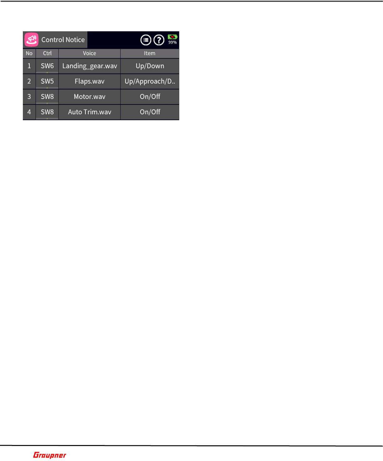
Graupner mz-32 / mz-16 Help Reference Manual
Page 33 of 44 Help-Ref-EN-V1.1
S04S1
CONTROL NOTICE
In the Control Notice menu, you can select switches
(Input Control) that will trigger announcements based
on their position.
Tap on the page icon, next to Help icon, to set the
Notice Group as global or phase dependent.
Tap on the plus sign (only visible if no Control Notice
has been configured) or the number field of an existing
Control Notice to add a Control Notice.
Tap on the Ctrl field to assign a switch (Input Control).
Tap on the Voice field to select a voice from the voice
file directory.
You can also create your own voice files using the grStudio software.
Tap on the voice file of your choice and on the check mark icon to select the file and exit
the directory by tapping on the exit icon (closing door).
Tap on the Item field to select from a list of preset notice states.
None Only the selected voice file is used for the announcement.
Position Different announcements for a control depending on the position.
Value Notifies the channel position in percentage.
On/Off Notifies the state of the control.
Start/Stop Notifies the state of the control.
Up/Down Notifies the state of the control.
Yes/No Notifies the state of the control.
Open/Closed Notifies the state of the control.
Left/Right Notifies the state of the control.
Left/Center/Right Notifies the state of the control of a 3-state control.
Empty/Half/Full Notifies the state of the control of a 3-state control.
Low/High Notifies the state of the control.
Low/Medium/High Notifies the state of the control of a 3-state control.
Up/Approach/Down Notifies the state of the control of a 3-state control.
Tap on the Delay field, which opens the edit tool bar to set a delay between repeated
announcements. This setting is only applicable if a repeat Cycle greater than 1 has been
set.
Tap on the Cycle field to set how many times an announcement will be repeated.
Tap on the Play button to listen to the notification, based on the current settings.
S05S1
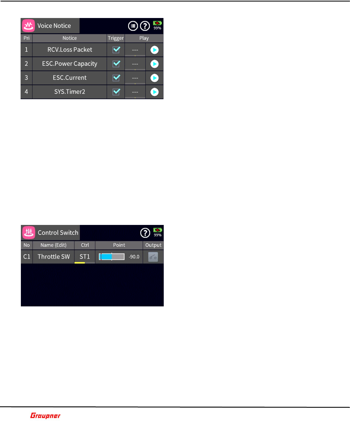
Graupner mz-32 / mz-16 Help Reference Manual
Page 34 of 44 Help-Ref-EN-V1.1
VOICE NOTICE
In the voice notice menu, you can assign controls to
telemetry notifications which can be activated manually
with a switch (Input Control) or played sequentially
with a preset delay.
Tap on the plus sign (only visible if no Voice Notice has
been configured) or the number field of an existing
Voice Notice to add a Voice Notice.
Select a Notice from the list of telemetry modules (left
column) and the available notifications for that module
(right column).
Tap on the Trigger checkbox to include or exclude this
Notice in the repeat string, if one was activated (explained further on).
Tap on the left field in the Play column to assign a switch (Input Control) to this Notice. It
will only announce this specific Notice. You can test the voice notice by tapping on the play
icon.
You can also assign a master Trigger switch (Input Control) that will cause the
announcement of all the previously configured notices. These Notices will be repeated based
on the Delay setting.
Assign a Repeat switch (Input Control) that will cause to repeat the last Notice based on
the Delay setting. The repeat switch is only applicable when the Trigger switch (Input
Control) is NOT active, otherwise all notices will be announced anyway.
Tap on the page icon which will switch to the screen to assign a switch (Input Control) to
the Trigger and/or Repeat functions.
Tap on the Group icon, to set the Voice Notice Group as global or phase dependent.
S06S1
CONTROL SWITCH
A Control Switch enables the trigger of an On/Off
condition based on the position of a specific control.
For example, a Control Switch can be configured that
an On/Off output is triggered when a throttle stick
reaches a certain position.
Tap on the plus sign (only visible if no Control Switch
has been configured) or the number field of an existing
Control Switch to add a Control Switch.
Tapping on the Name field will activate the edit toolbar
to rename or delete the Control Switch.
Tap on the Ctrl field to assign a switch (Input Control)
to the Control Switch.
Tap on the Point field to set the trigger point for the Control Switch. The edit tool bar will
be activated. Use the slider control bar for large value changes or the arrow keys for smaller
changes.
When the trigger point is reached, the Output icon will turn orange and indicate an on
condition for the Control Switch.
S07S1
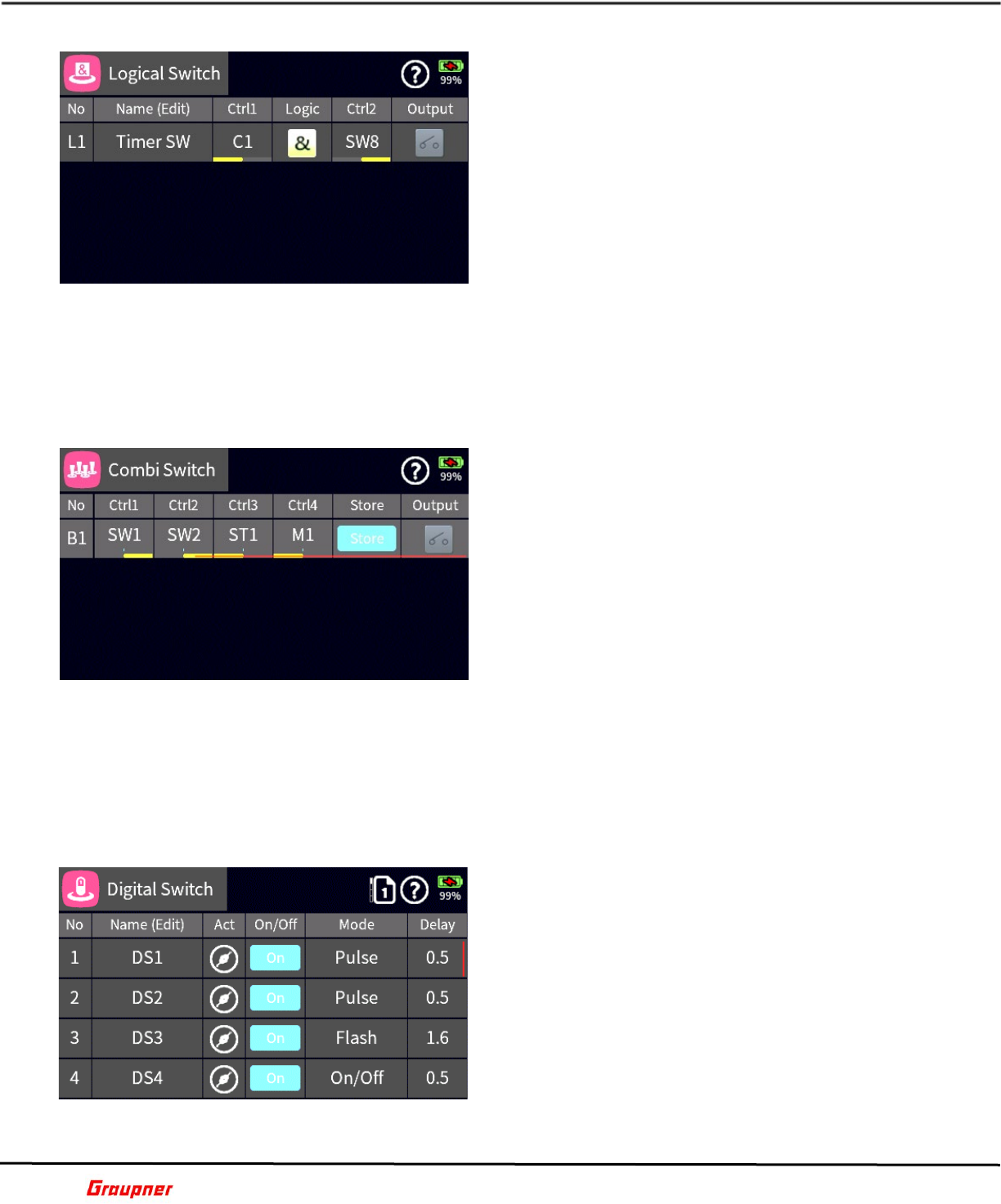
Graupner mz-32 / mz-16 Help Reference Manual
Page 35 of 44 Help-Ref-EN-V1.1
LOGICAL SWITCH
A Logical Switch triggers an On/Off condition
depending on the input of two different switches (Input
Control) that meet a certain logic condition.
Tap on the plus sign (only visible if no Logical Switch
has been configured) or the number field of an existing
Logical Switch to add a Logical Switch
Tapping on the Name field will activate the edit toolbar
to rename or delete the Logical Switch.
Tap on the Ctrl1 field to assign a switch (Input Control)
to the first Logical Switch input.
Tap on the Logic field to select the Operator for the
Logical Switch.
Tap on the Ctrl2 field to assign a switch (Input Control) to the second Logical Switch input.
Once the logical condition has been met after by the control inputs, the Output icon will
turn orange and indicate an On condition for the Logical Switch.
S08S1
COMBI SWITCH
A Combi Switch combines the On/Off conditions of up
to four different switches (Input Control) to trigger an
On/Off condition for the Combi Switch.
Tap on the plus sign (only visible if no Combi Switch
has been configured) or the number field of an existing
Combi Switch to add a Combi Switch.
Tapping on the Name field will activate the edit toolbar
to rename or delete the Combi Switch.
Tap on the Ctrl1 field to assign a switch (Input Control)
to the first control input.
Repeat the same for each control input you would like
to add. You do not need to assign an input for all four controls.
Position each switch (Input Control) in the desired position/condition and tap on the Store
field to save this setting.
If the condition of the saved setting is matched, the Output icon will turn orange and
indicate an On condition for the Combi Switch.
S09S1
DIGITAL SWITCH
Depending on your radio model you can assign up to
64 digital switches. Each of these 64 Digital Switches
can be arbitrarily placed as a widget on one of the
widget pages and operated from there.
Available Digital Switch Modes are:
ON/OFF (This will manually toggle the output)
Pulse (This will turn On the Digital Switch only ONCE
for the time set in the Delay field and then reset the
switch. It is necessary to manually tap again on Digital
Switch field in order repeat the operation
Flash (This will cycle/oscillate the digital output
between the On and Off as long the Digital Switch is turned On. The duration of the On and
Off time is set in the Delay field.
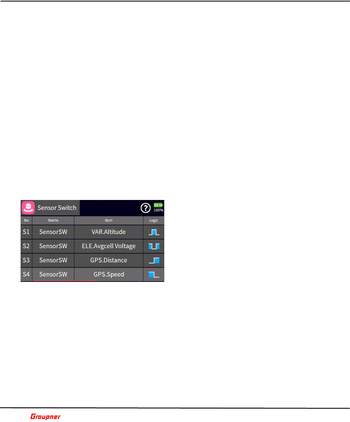
Graupner mz-32 / mz-16 Help Reference Manual
Page 36 of 44 Help-Ref-EN-V1.1
On the receiver side, these digital switches can be assigned to a channel. The mapping of
a digital switch to a receiver channel as output can be done either in the “RF Set” menu
(Base section) or directly in the receiver using the Telemetry Setting & Data View ASCII
menu. (Check the Telemetry Help information in this Help section on how to access the
Setting & Data View ASCII menu.)
IMPORTANT: This feature is only available with receivers that have been updated with the
current firmware release.
Tapping on the Name field will activate the edit toolbar to rename or delete the Digital
Switch.
Tap on “Act” icon in the respective line to activate a Digital Switch.
Tap on the Mode field to select the desired mode (On/Off, Pulse or Flash).
Tap on the Delay field to set the delay time for the Pulse or Flash mode.
Example:
Connect a servo to the receiver channel which has been mapped as Digital Switch to test a
Digital Switch.
Go to the Home screen and select an empty deck or an available block and activate the
Widget Editor (Tap and briefly hold down on the block).
On the Add New Widget screen select System and then “Digital Switch”. Tap on Digital
Switch number/name which was assigned in the previous step.
Test the operation by tapping the Digital Switch field on the Widget deck.
You can change its behavior in the “Digital Switch” submenu.
S10S1
SENSOR SWITCH
A Sensor Switch provides the means to enable a
function or control based on telemetry data.
For example, you can create a Sensor Switch that when
a preset altitude has been reached or exceeded the
motor will be switched off or throttled back, until you
regain your preset altitude.
Another example is when you are in landing mode, your
ground speed is at a certain value and you forgot to
deploy your landing gear. A voice notification will alert
you and/or the landing gear will automatically deploy.
There are many uses for sensor-based switches that
can assist you with added functionality and safety.
To add a new Sensor Switch, tap on the plus icon or on the No field of an existing sensor
switch entry.
A dialog will provide a list of sensors and their corresponding telemetry functions to choose
from. Note, you must have the corresponding telemetry module installed to utilize the
respective telemetry functions.
For example, if you have a General Air Module installed and you want to use the average
cell voltage for a switch, select General/Avgcell Voltage from the dialog.
The Item column lists which module and telemetry function is used for the sensor switch.
In this example it would be GEN.Avgcell Voltage.
The logic field determines as to how the measured sensor value is evaluated in real-time.
The options are:
• Less than
• More than
• Between
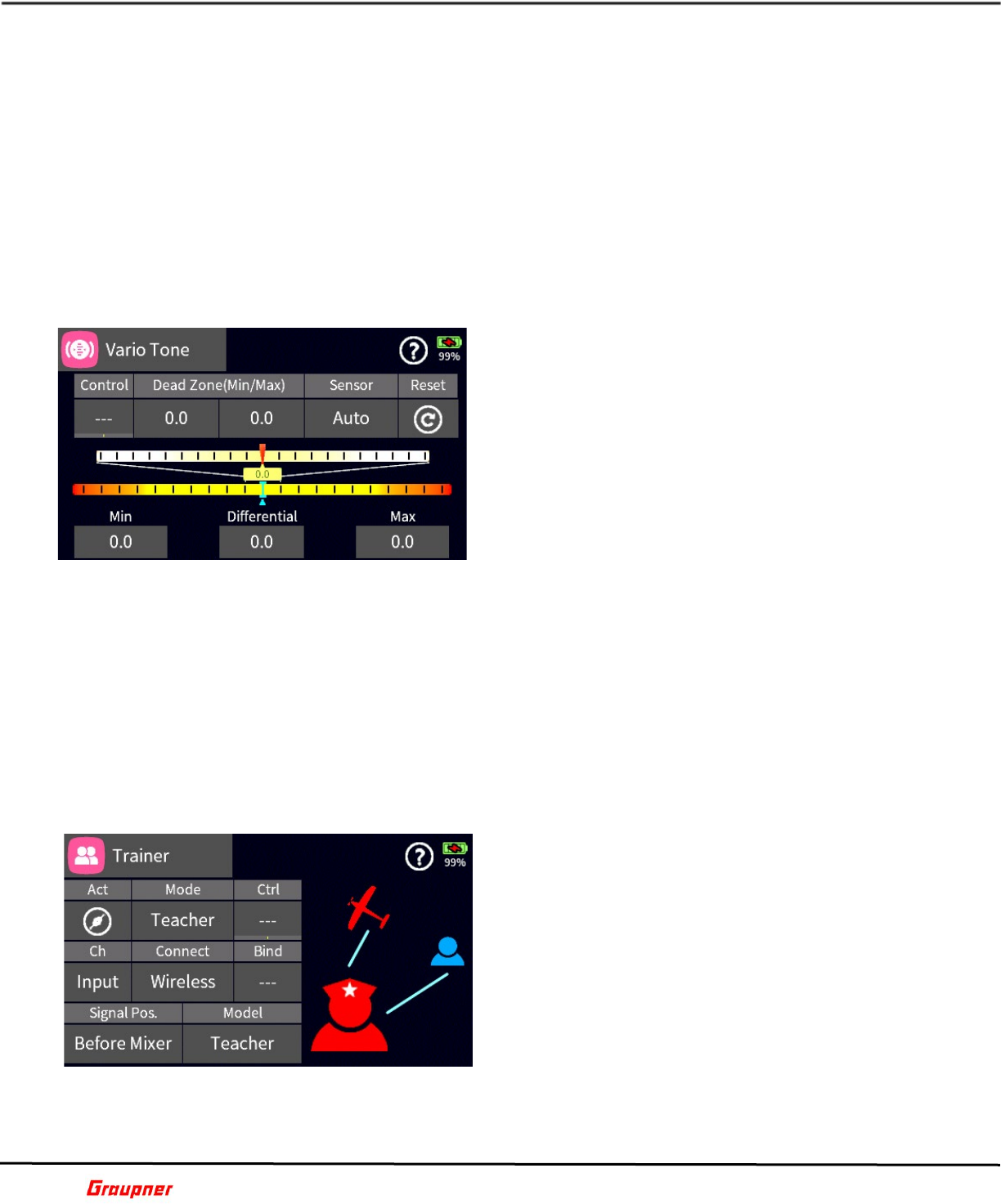
Graupner mz-32 / mz-16 Help Reference Manual
Page 37 of 44 Help-Ref-EN-V1.1
• Less than or more than
The Range1 and Range2 fields are used to set the sensor switch trigger values.
For example, you can create a condition that a cell voltage between 3.5 and 3.7 volts will
activate the switch. Another setting could be that a value of 3.5 volts or less will activate
the Sensor Switch.
The Hold provides the option to assign a Select Input Control which will hold or release the
current Sensor Switch output. It is like a latch function, the Sensor Switch will not
deactivate when the sensor reading returns within the set range, unless the Select Input
Control has the correct condition. This can be of use in situations where a certain condition
needs to be first dealt with and resolved, before clearing the output.
The Output column will show the state of the sensor switched On or Off.
S11S1
VARIO TONE
When an appropriate sensor (i.e. GPS, Vario) is
installed, the model can provide altitude information as
well as climb or descent information. For example, this
function is useful for sailplane pilots to know whether
the glider is in a sink or climb state.
The user is notified by a range of high or low pitched
audible tones to indicate the state of the glider.
Tap on the Control field to assign a switch (Input
Control) to activate or de-activate the Vario Tone
function.
Tap on the two Dead Zone (Min/Max) fields to set the
range in which no Vario tone output should occur. This is essentially a dead band.
Tap on the Sensor field to select the sensor for the Vario Tone. This is applicable when
multiple sensors are installed.
Tap on the Reset icon to reset the Min/Differential/Max values.
The Min field value on the bottom of the screen provides the highest (worst) sink rate, while
the Max field value provides the highest (strongest) climb rate. The Differential is the
current difference between Max and Min.
You can assign a volume control (for example DV1) for the Vario Tone in the System -
Sound Set menu.
S12S1
TRAINER
You can use your Graupner radio for training purposes
in a Teacher/Student mode. This operation can be
done wireless with two Graupner radios or with a cable
between a Graupner radio and other transmitter
brands, using the DSC port on the back of the radio.
Tap on the Act icon to activate Trainer mode.
Tap on the Mode field to designate the function of the
radio as Teacher or Student.
Settings specific to Teacher Mode
Tap on the Ctrl field to assign a switch (Input Control)
for the teacher to take or release control from the
student.
Tap on the Ch Input field which will activate a new screen with following options:
Tap on the name in the Channel column to assign a different channel for Input.
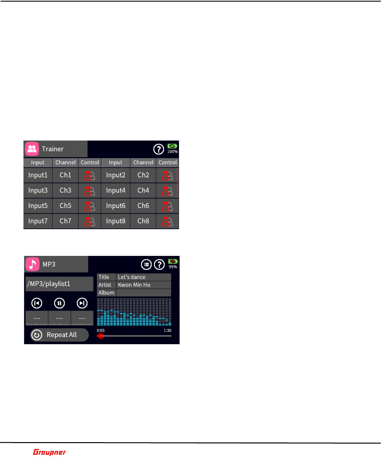
Graupner mz-32 / mz-16 Help Reference Manual
Page 38 of 44 Help-Ref-EN-V1.1
Tap on the Control field to select which channels are released for Student control (color will
change from red to blue). You can select from a maximum of sixteen channels.
Close screen by tapping on Trainer icon, upper left corner of screen.
Tap on the Model field to select which model is bound to the appropriate transmitter.
Settings specific to Student Mode
Tap on the Ch field to assign a different channel to an Output of the transmitter.
Tap on the Connect field to set the connection mode of wireless or DSC. If wireless is
selected, you will need to bind to a Graupner radio.
Tap on the Bind field to initiate a bind to the Teacher or Student transmitter. Both
transmitters must be in bind mode for a successful binding.
Tap on the Signal Pos. to select if also programmed model memories can be used for
student operation when in Teacher mode.
S13S1
TRAINER CHANNELS
In the channel menu you can select which channels are
released for student control and which sequence.
Tap on the Channel number to change the input /
output of channels if needed.
Tap on the Control icon to enable student control for
that channel.
S13S2
MP3
Depending on your radio model (optional feature on
some models), you can play MP3 files on your
transmitter. MP3 files need to be copied to the MP3
folder on the installed SD card. This can be done after
placing the radio in Mass Storage mode.
Tap on the /MP3/**** field to select from the available
play lists.
Tap on the fields previous/play/next fields to assign a
switch (Input Control) for each function.
Tap on the Repeat field to select a MP3 play mode. The
available modes are Repeat Off, Repeat Once, Repeat
List and Repeat All.
Tap on the menu icon next to the help icon for additional options.
You can assign a volume control (for example DV1) for the MP3 player in the System -
Sound Set menu.
Tap and hold on the red dot of the play progress line below the equalizer display to move
to a certain time.
S14S1
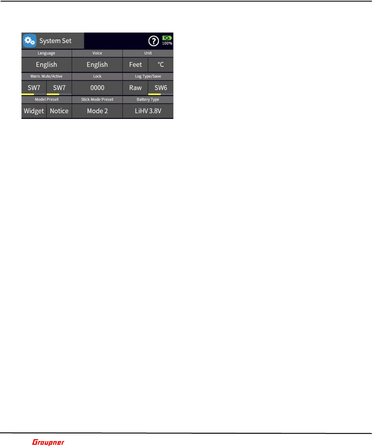
Graupner mz-32 / mz-16 Help Reference Manual
Page 39 of 44 Help-Ref-EN-V1.1
SYSTEM Menu
SYSTEM SET
In the System Set menu you can customize certain
operations and behaviors of your radio.
Language – Tap on the Language field to change the
display language of your radio.
Voice – Tap on the Voice field to change the language
of voice announcements. In case the desired language
is not available a resource update has to be performed
using the grStudio software. The radio will ask for a
restart after a different voice language has been
selected
Unit – Tap on the Unit fields for distance or temperature
to change the display and announcements between metric (Meter, Celcius) or imperial
(Feet, Fahrenheit) units.
Warn. Mute/Active – A switch (Input Control) can be assigned by tapping on the Warn.
Mute or Active field. The Warn. Mute field will permit to turn off warnings, while the Active
field will reactivate the warnings. It is important to re-activate the system warnings after
muting them to ensure new alerts are not missed.
Lock – When a lock code is set in the lock field the radio needs to be unlocked with that
code. The default code is 0000 which disables the lock function.
Log – Tapping on the Log field will permit you to choose between the file formats of Raw
or ASCII for the log file. The default is Raw.
Log Start/Stop – Telemetry data logging is automatically started the moment RF is switched
on. It’s important to take advantage of data logging as the radio will record important
operational data. In many cases Graupner is not able to provide support to its customers
without a log file.
You can still have manual control over telemetry data logging by assigning a control to
start/stop logging. In case there is no control assigned logging can also be started and
stopped by pressing the double arrow key (lower key left of screen).
Graupner recommends leaving telemetry data logging always on when RF is active.
Model Preset – The Widget and Notice fields permit you to save and then recall/load your
specific configurations.
Model Preset – Widget Create your own Widget decks and save them as a preset. Following
each newly created model will use the preset file to display the widgets. Loading a widget
preset will overwrite the current widgets.
Model Preset - Notice – System notices are stored in a notice preset file that contains all
relevant information for system and telemetry information announcements. The messages
can be found in the Special Menu under the Sensor Notice menu. You can create your own
presets by selecting the notifications you would like to use and then save the configuration
via the Notice field. Each newly created model will use the preset file for sensor notices.
Loading a sensor preset, will overwrite the current sensor notices.
Stick Mode Preset – Determines the stick mode used when a new model is created. The
default mode is defined during the initial radio setup or a Factory Reset.
Battery Type – LiPo/LiIo with a cell voltage of 3.7 volts or LiHV with a cell voltage of 3.8
volts. Never set the voltage mode at 3.8 volts when a LiPo/LiIo 3.7 volts battery is used.
G01S1
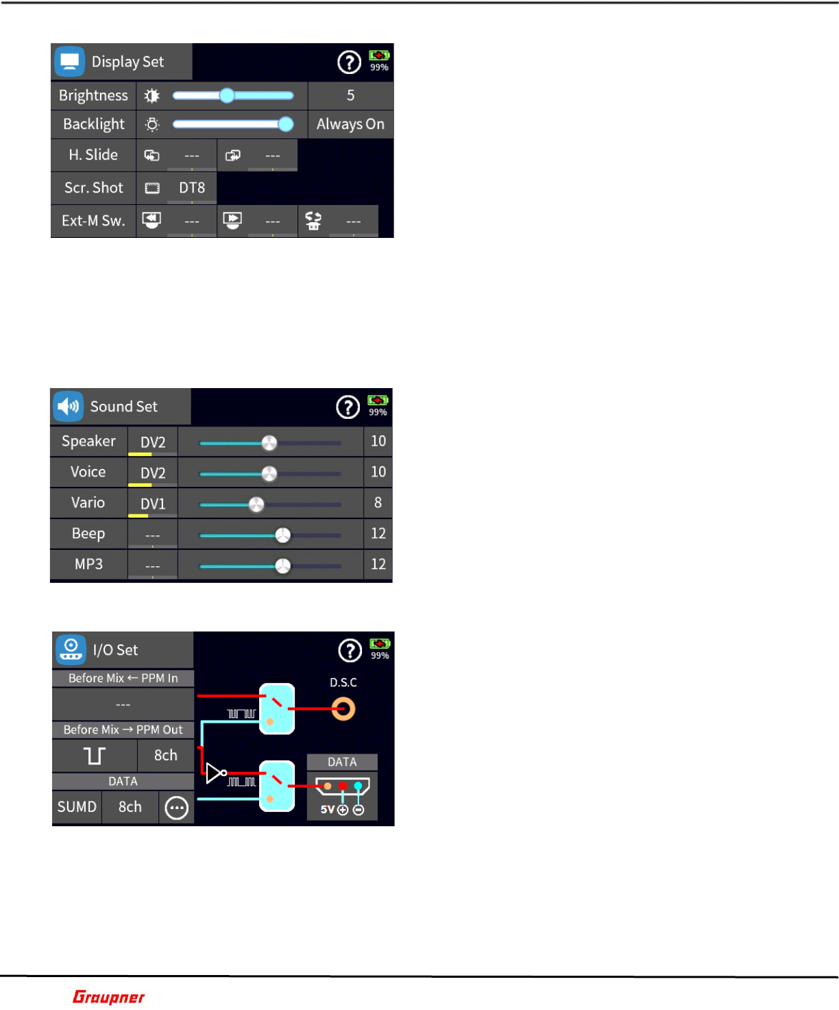
Graupner mz-32 / mz-16 Help Reference Manual
Page 40 of 44 Help-Ref-EN-V1.1
DISPLAY SET
In the Display Set menu you can control all your
display settings.
Brightness – Set the screen brightness between 1 – 10.
Backlight – Determines the time before the screen will
dim. You can set a time between 5 seconds and always
on. Briefly tapping the power button will undim the
screen. The screen can also be dimmed/undimmed at
any time, by briefly tapping the Power button.
H.Slide – You can assign switches (Input Control) for
paging the display. They will function identical to the
radio arrow keys (top 2 keys left of screen).
Scr.Shot – Assign a momentary switch to take a screenshot of any active screen, which is
stored in the Screenshot folder of the SD Card.
Ext-M Sw. – Applicable when using an external monitor such as the Graupner Smart-Box.
Tap on the respective field to assign navigation switches (Input Control) for scrolling
between the screens and changing the sensor display.
G02S1
SOUND SET
In the Sound Set menu you can assign volume controls
for the various sound sources by tapping on the
respective field.
The Speaker volume is the main volume control for the
radio, while the volume for Voice, Vario, Beeps and the
MP3 player can be individually controlled. The volume
can be adjusted between 0 (Off) and 20.
G03S1
I/O SET
The I/O set menu is used to configure what channel
information/data is available at the back-panel
connectors of the radio. The switch positions can be
changed by tapping on the switch symbols.
Inputs and outputs can be configured for certain data
formats.
Before Mix – PPM In – Shows the number of channels
that are recognized by the PPM DSC input and available
for student mode operation.
Before Mix – PPM Out – Selection of the output
waveform (normal/inverted) and the number of
channels for output on the DSC and/or Data port.
The DATA fields control the output protocols available on the DATA port.
SUMD – This is Graupner specific protocol. You can set the number of output channels and
the channel mapping for your setup.
SP – This is a Spektrum specific protocol. Tapping on the field next to SP will open another
window for additional settings. Select Mode, Channel, Bind and Range Test for an external
Spektrum RF module
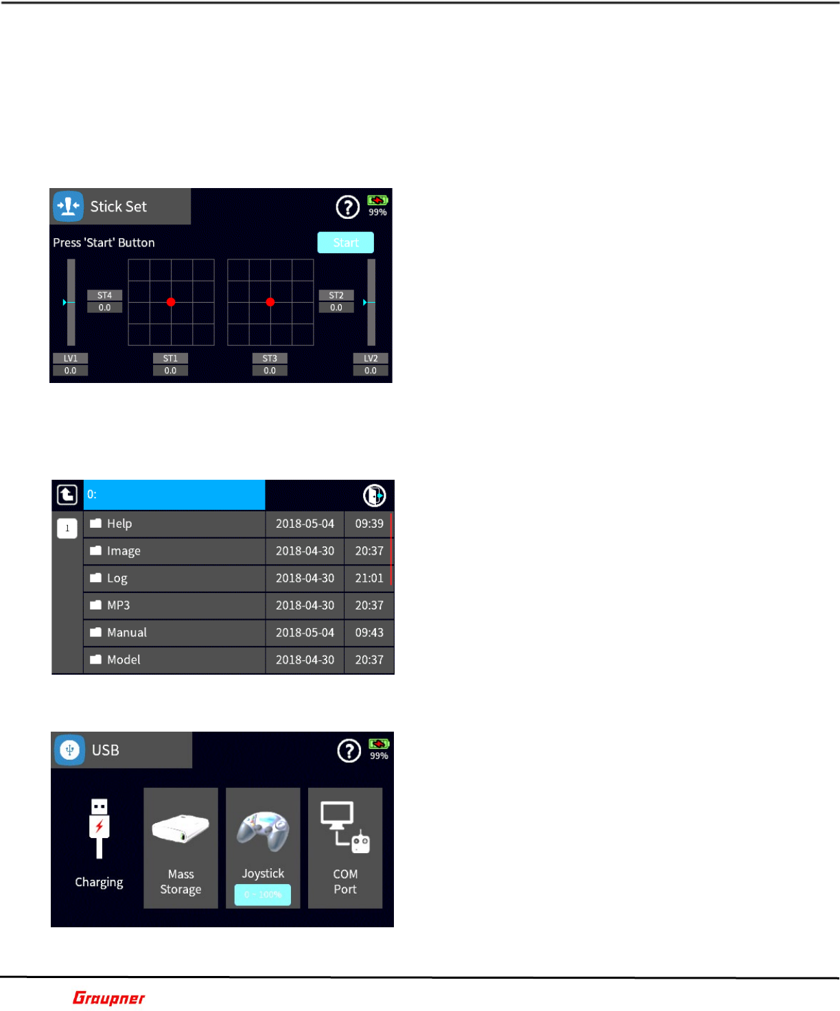
Graupner mz-32 / mz-16 Help Reference Manual
Page 41 of 44 Help-Ref-EN-V1.1
S-BOX – View the telemetry information on the screen of a connected Graupner Smart-
Box.
EXT-M – View the telemetry information on the screen of a connected Smart-Box.
CRSF – When a TBS CROSSFIRE module is used the proper version must be selected. If
required, you can map the channels.
Tapping on the DATA port icon will turn the power to the attached module (5V) On and Off.
G04S1
STICK SET
It is recommended to calibrate your radio controls
before first time use and periodically when the stick
controls are not centering.
To calibrate the sticks, center all controls so that the
line up with the center position 0.0 for each control
axes. This can be confirmed by briefly switching to
Servo View, pressing the Servo View key (upper key
right of display).
Tap on the start button and ensure all controls are
centered.
Move all the controls to their minimum and maximum
position.
If successfully completed tap on the Save button.
B13S2
FILE MANAGER
The file manager allows you to browse the SD Card
directories to copy and delete files.
Caution: Do not delete files if you are not sure about
the functionality.
To exit the file manager, tap on the upper right corner
exit icon (closing door).
G05S1
USB
In the USB menu you can select different USB
functions.
Charging – If the radio is connected to a power source
and being charged it will display the Charging
message.
Mass Storage – When selected it mounts the internal
SD card and maps it as a drive on a computer. When
Mass Storage is active no other functions can be
selected until that mode has ended. Tapping on the
Mass Storage icon will ask for confirmation to turn off
the function.
Joystick – Enables the radio as a joystick controller for use with flight simulators or games.
Some games may require setting the travel of 0-100% or -100% to +100% which can be
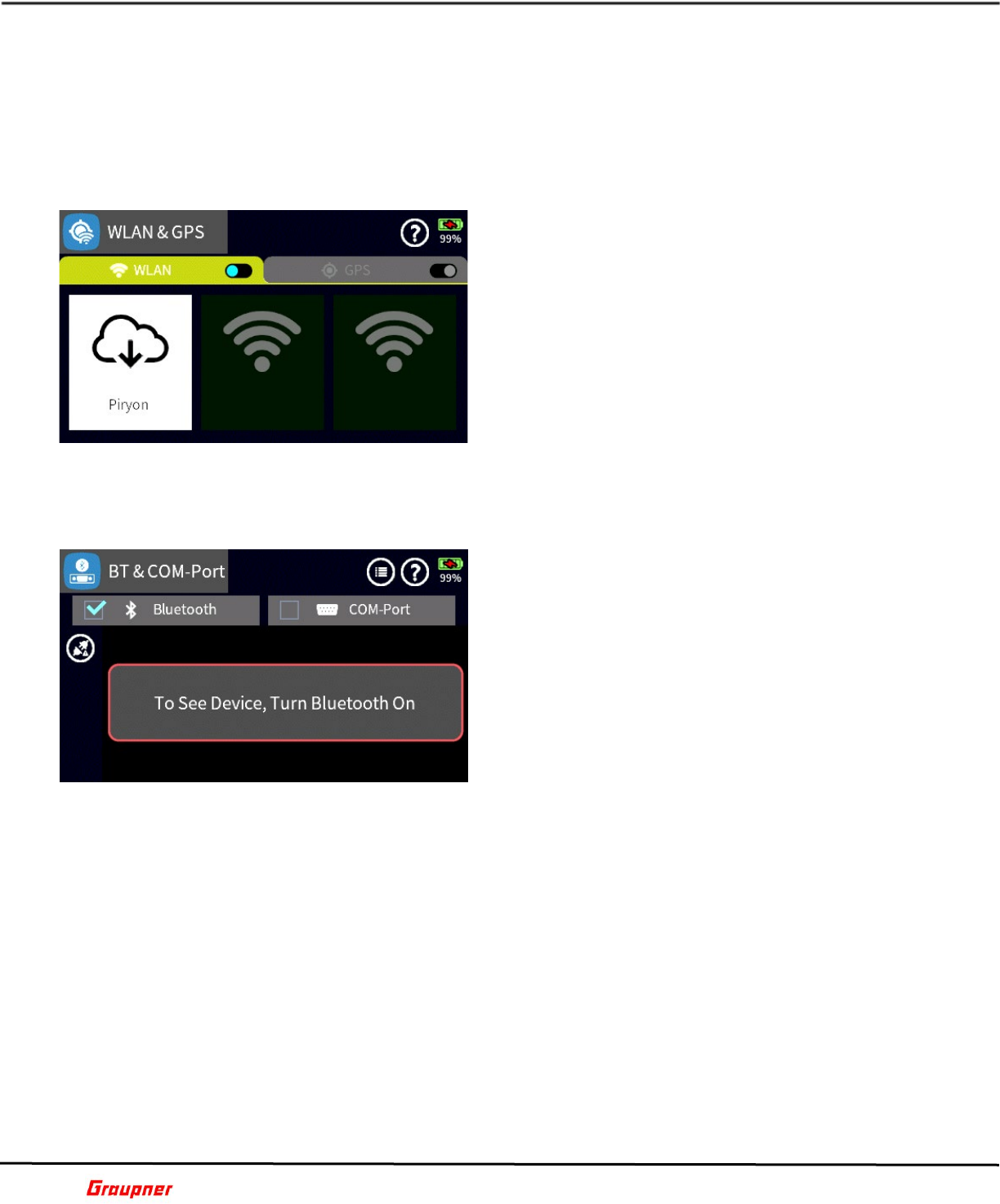
Graupner mz-32 / mz-16 Help Reference Manual
Page 42 of 44 Help-Ref-EN-V1.1
done by tapping on the blue icon below Joystick icon. When joystick mode is active no other
functions can be selected until that mode has ended. Tapping on the Joystick icon will ask
for confirmation to turn off the function.
COM Port – When activated the radio can communicate with the grStudio software for real-
time telemetry data viewing and logging. Tapping on the COM Port icon will ask for
confirmation to turn off the function.
G06S1
WLAN & GPS
In the WLAN and GPS menu you can establish a Wi-Fi
connection to your local network or activate a GPS
receiver if installed.
To activate the Wi-Fi connection first tap on the switch
icon (right in the WLAN tab), then tap on the WLAN
icon (cloud with arrow). A list of available networks will
be displayed. Select your network and enter your login
credentials if needed.
Note: The radio WLAN MAC address can be found in
System – Info & Update under ID Information. THIS IS
ONLY NEEDED when you use WLAN security settings
including the MAC address.
If there is an active connection the WLAN symbol will be lit on the main display.
G07S1
BT & COM Port
You can connect a Bluetooth™ device such as headset
or Smartphones to your radio for audio or data view on
Android Smartphones.
The serial COM Port provides the option to connect your
radio to external serial devices such as HoTT Viewer
App, Smart Box or HoTT OSD.
Tapping on the checkbox field selects the Bluetooth™
module.
Tapping on the icon (circle with plugs) will turn on
Bluetooth™.
Tapping on the magnifying glass icon searches for
nearby Bluetooth™ devices.
Found Bluetooth™ devices are displayed and the corresponding device can be selected for
connection.
Depending on the device, the password 0000 must be confirmed.
The search can be aborted by tapping on stop (red circle with line).
If there is an active connection, the Bluetooth™ symbol is lit on the main display.
G08S1
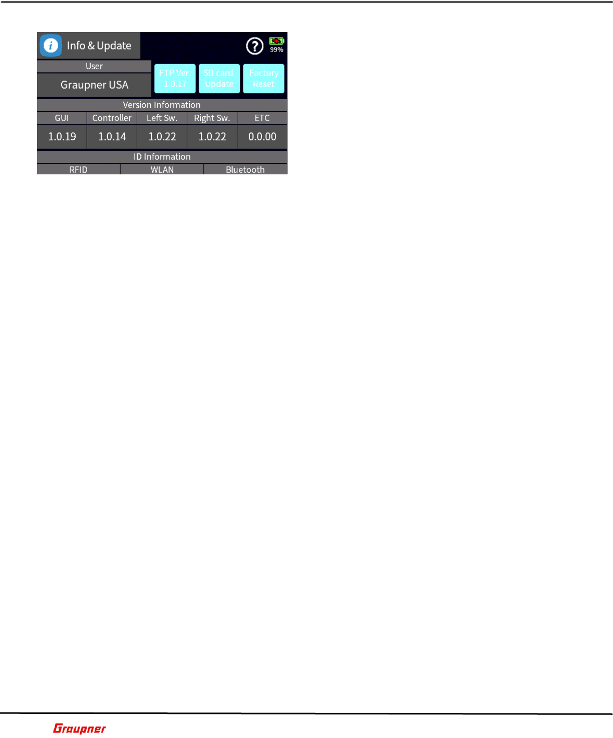
Graupner mz-32 / mz-16 Help Reference Manual
Page 43 of 44 Help-Ref-EN-V1.1
INFO & UPDATE
The Info & Update menu allows you to update your
radio firmware using your wireless network or
computer, as well as restoring your radio to the factory
default settings.
You can personalize your radio by tapping on the user
field which activates the keyboard for entering a user
name.
FTP Wireless Update
When a new firmware is available on the Graupner
update server the FTP blue field will show a red color
dot and the latest firmware version number is
displayed in the field. You can compare the current version shown in the GUI field with the
one in the FTP field.
Tapping on the blue FTP field will automatically start the wireless update after confirmation.
This process is fully automated. No user interaction is required. The update can take
between 2-10 minutes, depending on the size of the update and the network connection.
After completion the radio will automatically restart.
In case the update includes also system resources, such as voice and system files, tapping
on the FTP field will inform you that the update has to be performed by an SD card Update.
SD Card Update
An SD card Update can be done after the firmware has been downloaded to the SD Card
using the Firmware Upgrade Studio software (grStudio). The grStudio will download and
install any new and updated resource and system files, as well as the latest firmware
version.
Only the firmware installation needs to be initiated by the user. This is done by tapping on
the SD Card Update field and selecting the latest version by tapping on the filename. A
checkmark will be displayed left to the Help icon.
After confirming the installation, the radio will re-start and install the new firmware.
Version Information
You can scroll the menu to view any relevant information about your radio like firmware
versions, network details and function details. ID Information lists your radio RFID as well
as the MAC addresses for the WLAN and Bluetooth™modules.
G09S1

Graupner mz-32 / mz-16 Help Reference Manual
Page 44 of 44 Help-Ref-EN-V1.1
DISCLAIMER
These operating instructions are exclusively for information purposes and are subject to
change without prior notification. The current version can be found on the Internet at
www.graupner.com on the relevant product page.
In addition, the company Graupner/SJ has no responsibility or liability for any errors or
inaccuracies that may appear in construction or operation manuals.
Graupner cannot be held liable for printing errors.
