Gray WPLS Security Transceiver User Manual WPLS 160 67090347 RevJ
Gray Manufacturing Company, Inc. Security Transceiver WPLS 160 67090347 RevJ
UserManual.wiki
>
Gray
>
WPLS User Manual
User Manual
Navigation menu
Upload a User Manual
Namespaces
Wiki Guide
HTML
PDF
Info
Views
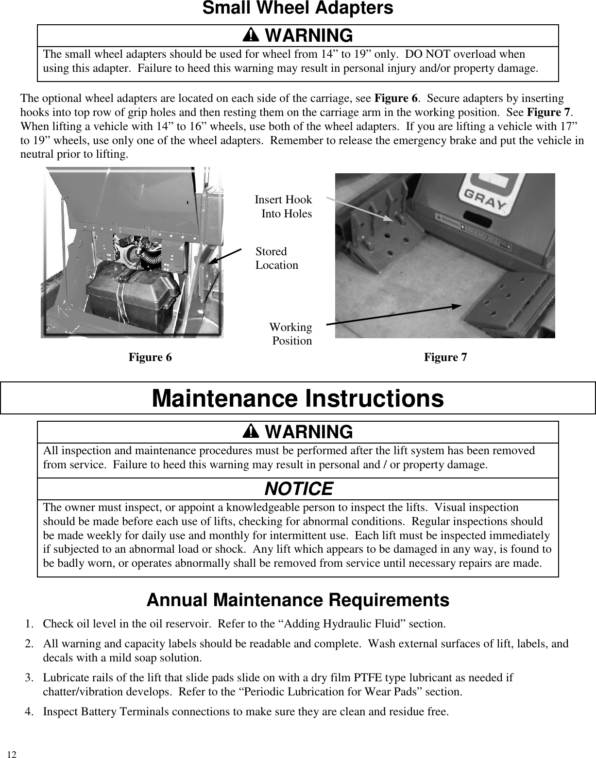
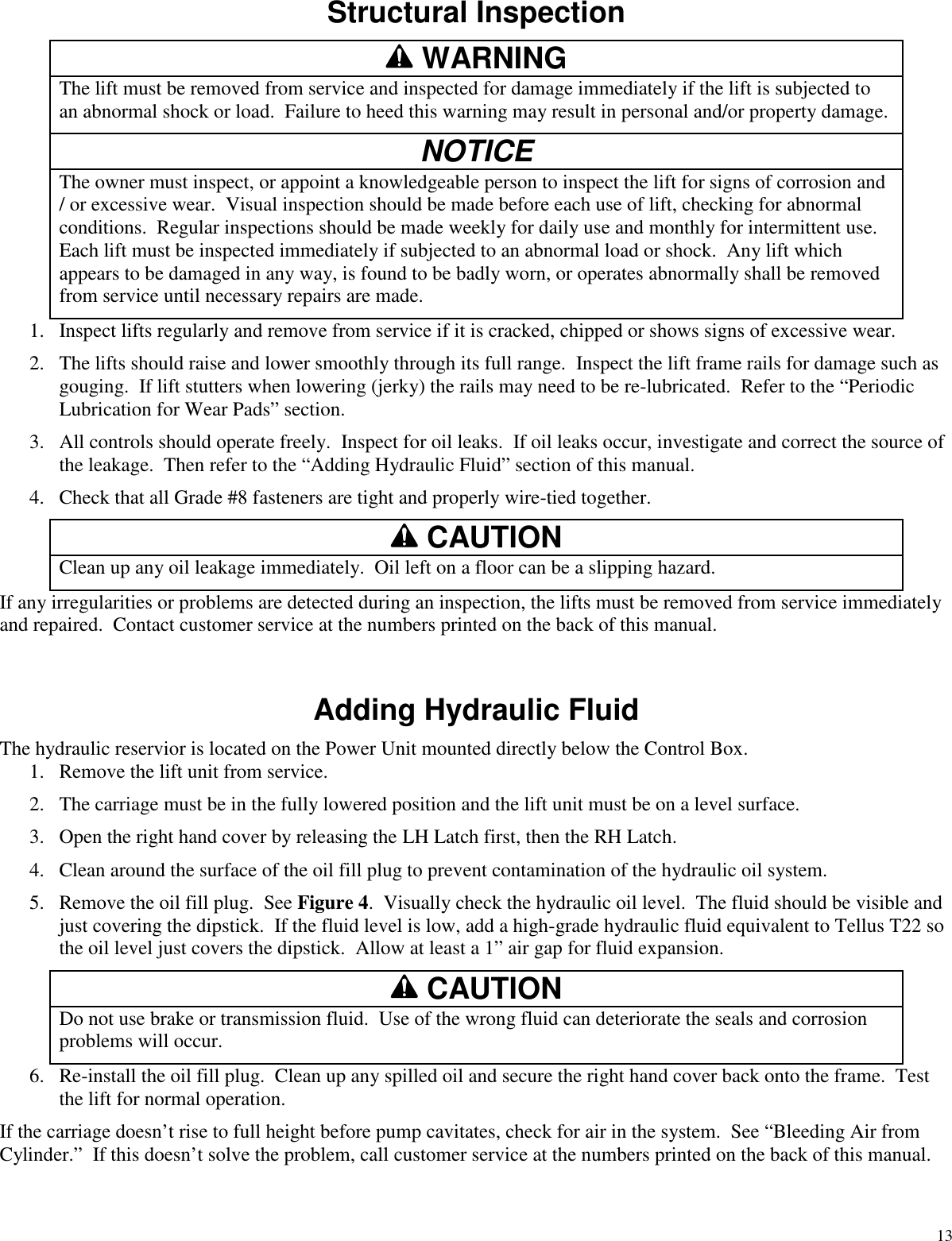
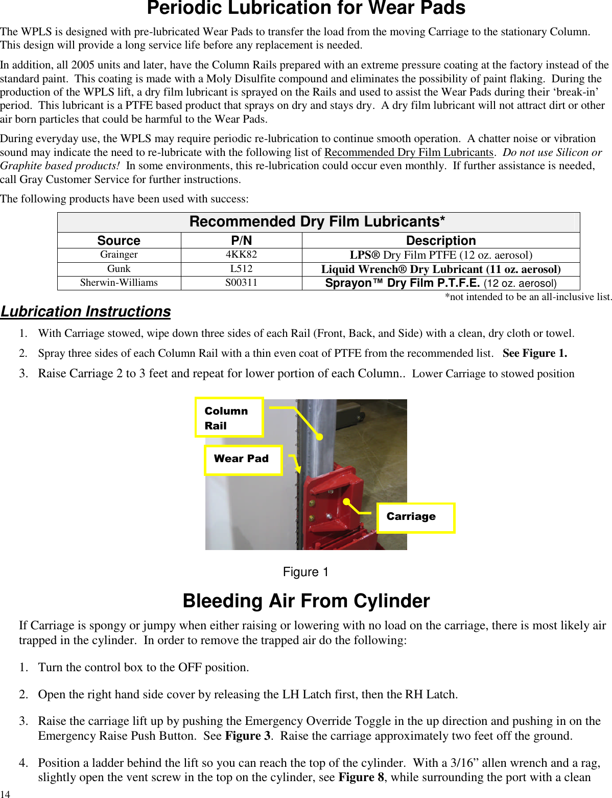
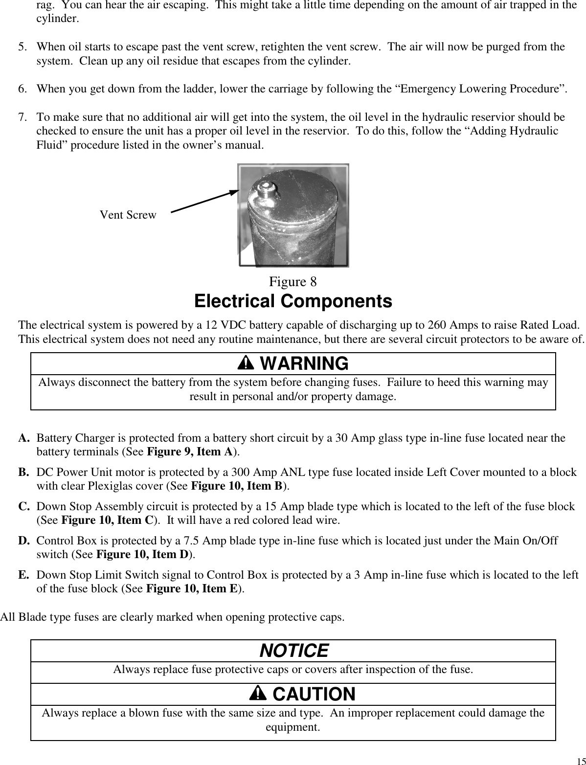
User Manual
Discussion / Help
Navigation