Gree Electric Appliances of Zhuhai W05AGL Wireless Gateway User Manual Wireless Gateway Owners Manual
Gree Electric Appliances, Inc. of Zhuhai Wireless Gateway Wireless Gateway Owners Manual
UserManual.wiki
>
Gree Electric Appliances of Zhuhai
>
W05AGL User Manual
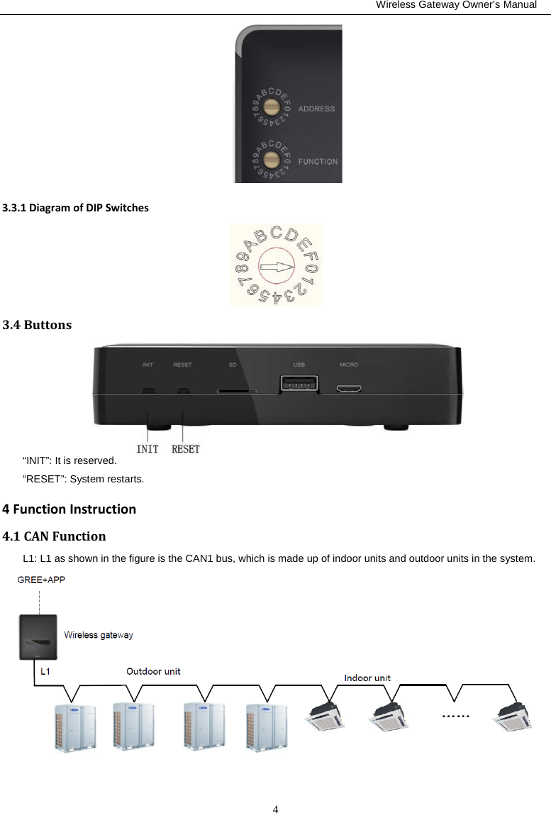
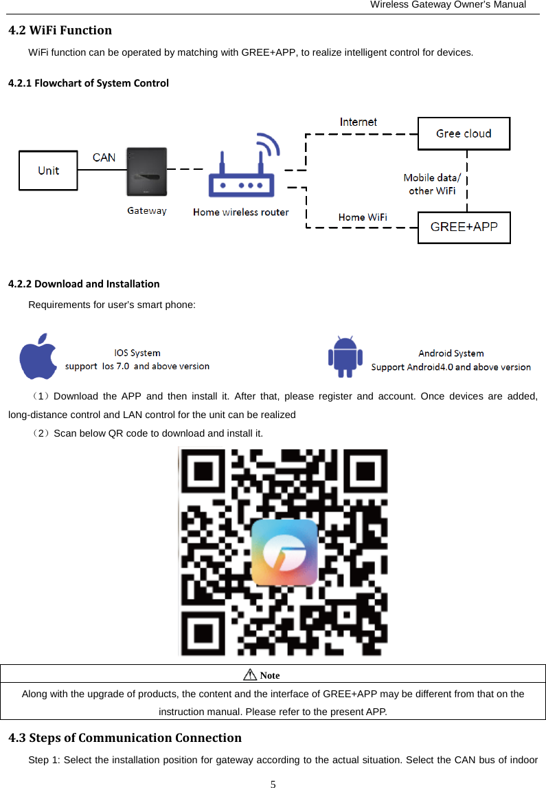
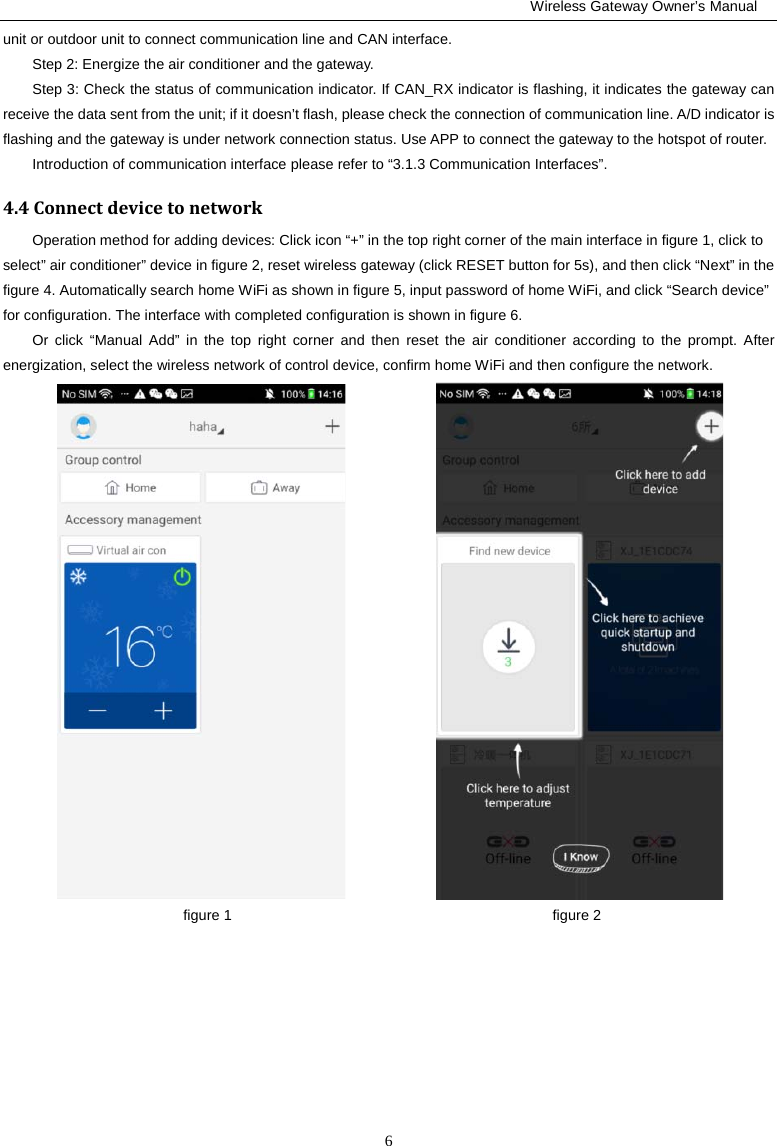
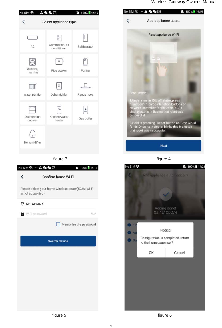
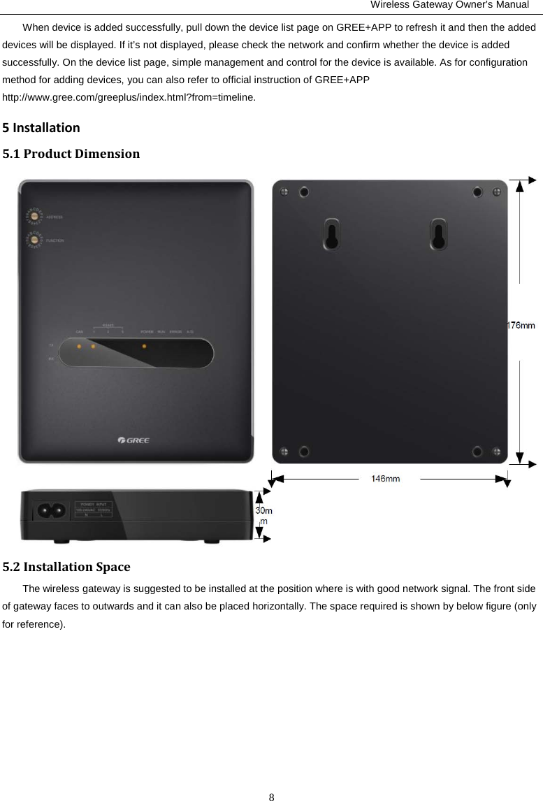
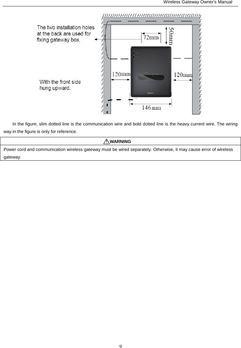
Wireless Gateway Owners Manual
Navigation menu
Upload a User Manual
Namespaces
Wiki Guide
HTML
PDF
Info
Views
User Manual
Discussion / Help
Navigation