Green Packet Berhad OX350I-GP WiMAX Outdoor CPE User Manual of WiMAX 3 5G Outdoor CPE for greenpacket Rev1 3 FCC Certification
Green Packet Berhad, Taiwan WiMAX Outdoor CPE of WiMAX 3 5G Outdoor CPE for greenpacket Rev1 3 FCC Certification
Contents
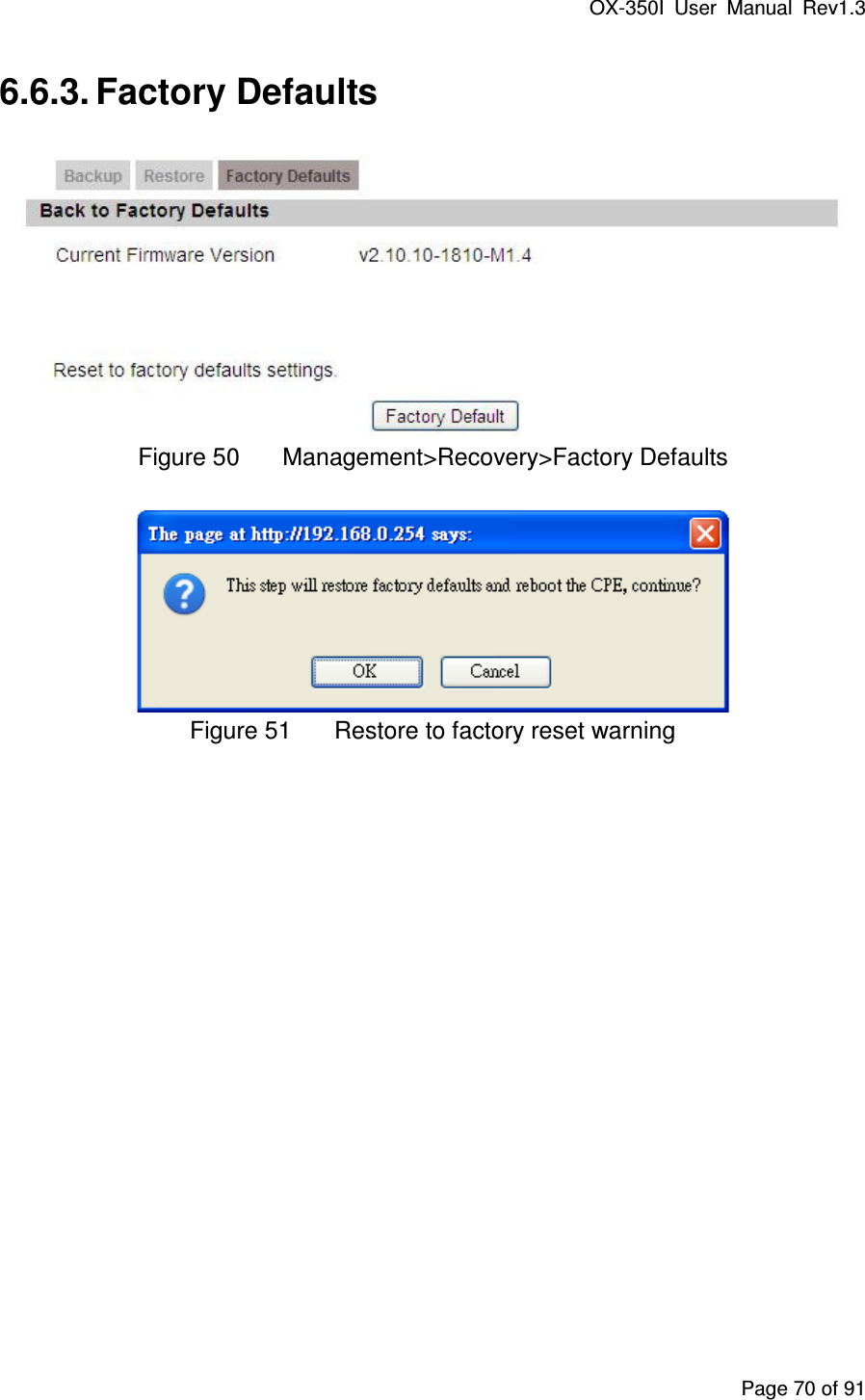
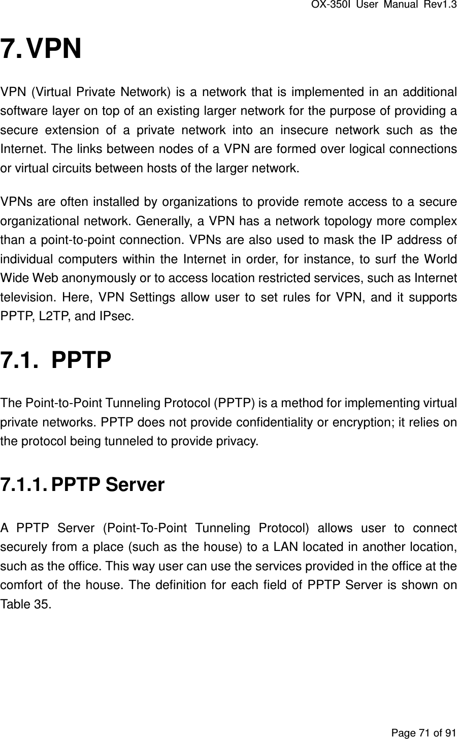
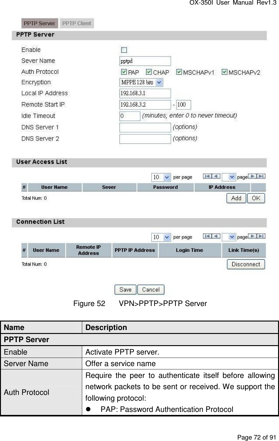
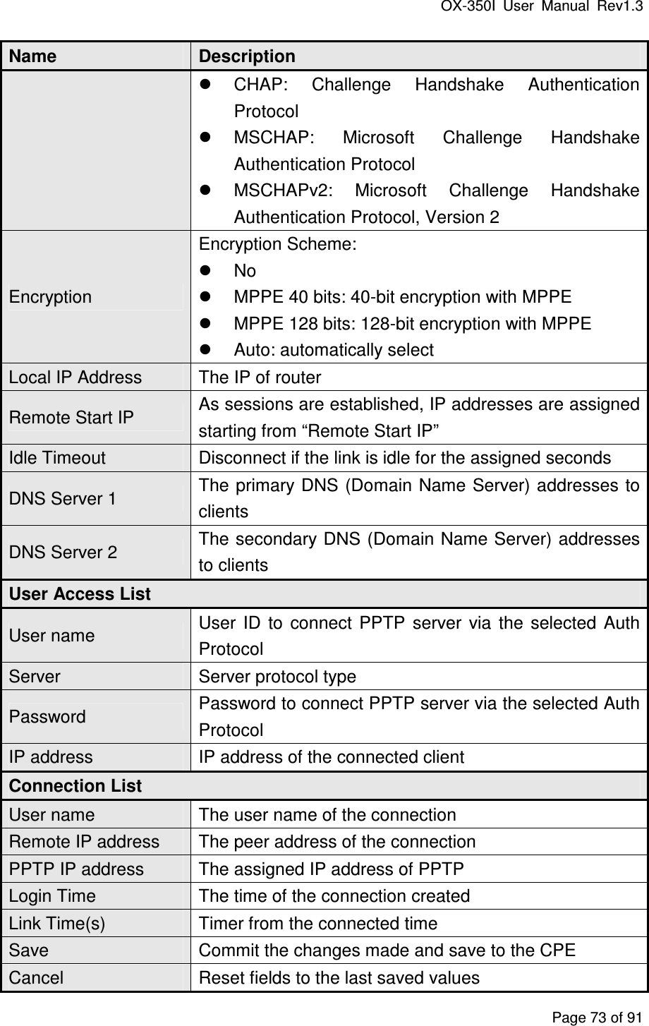
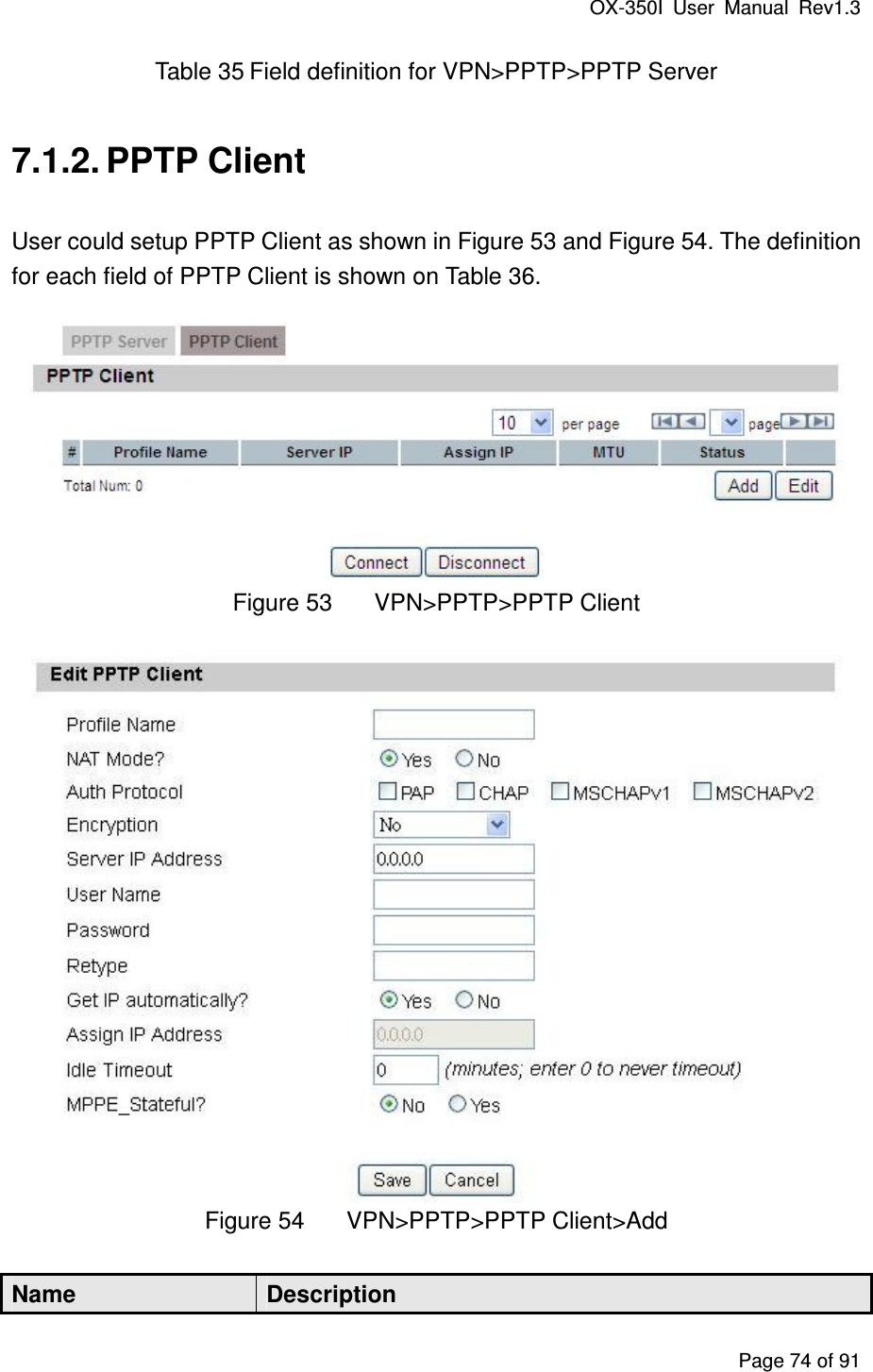
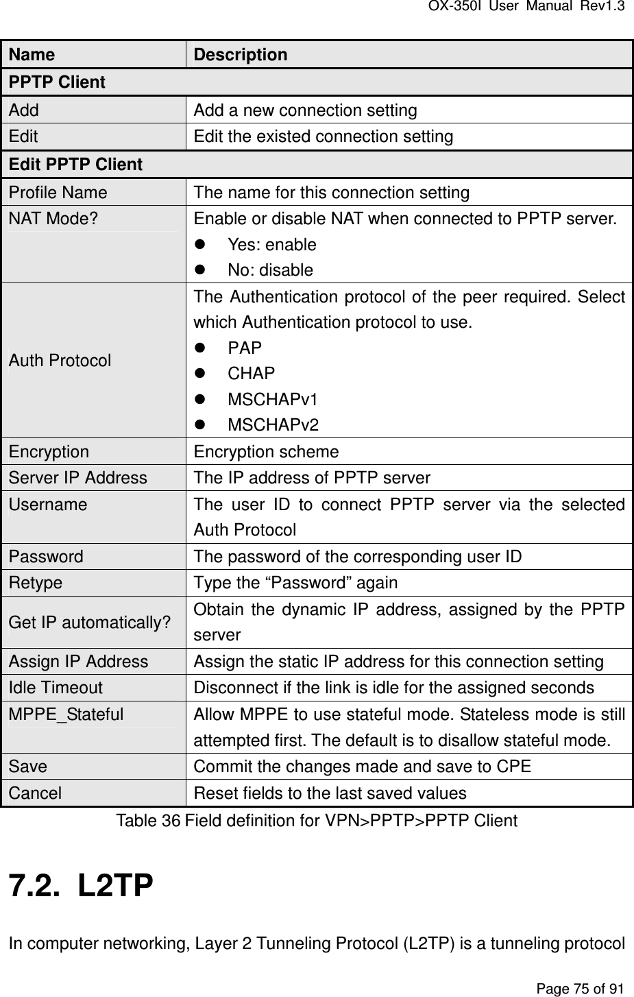
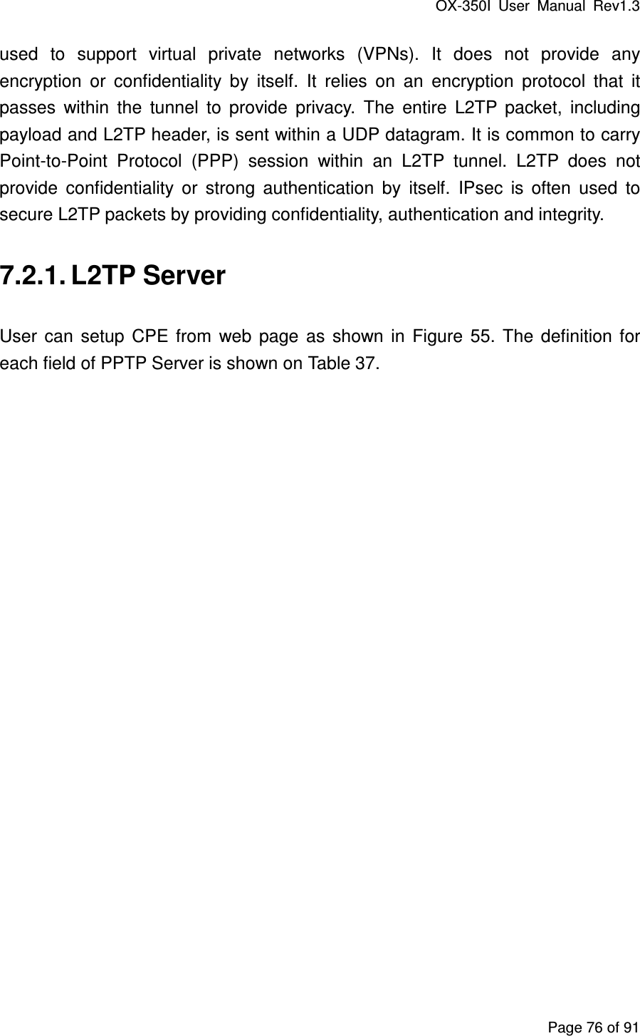
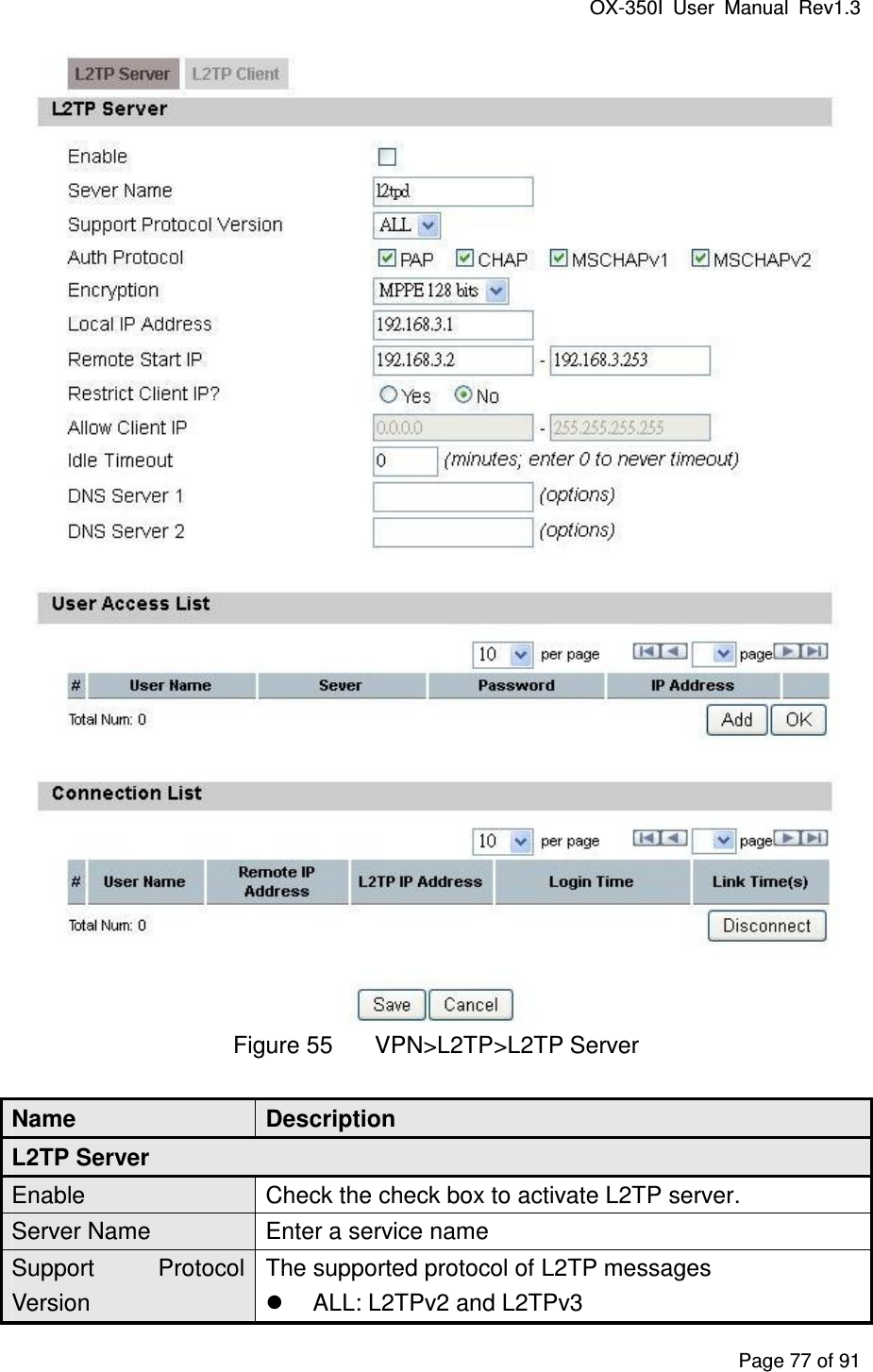
- 1. User manual rev1
- 2. UM
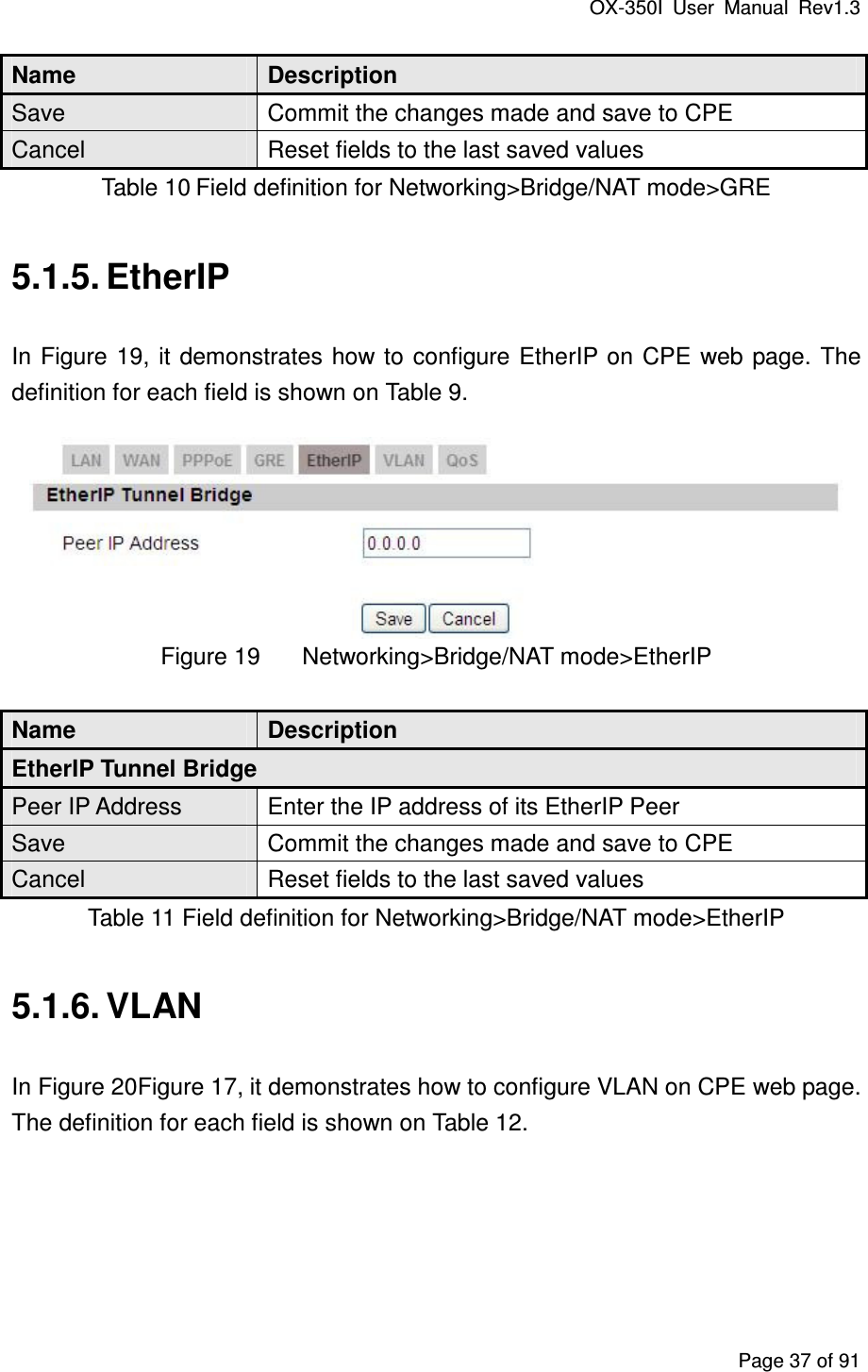
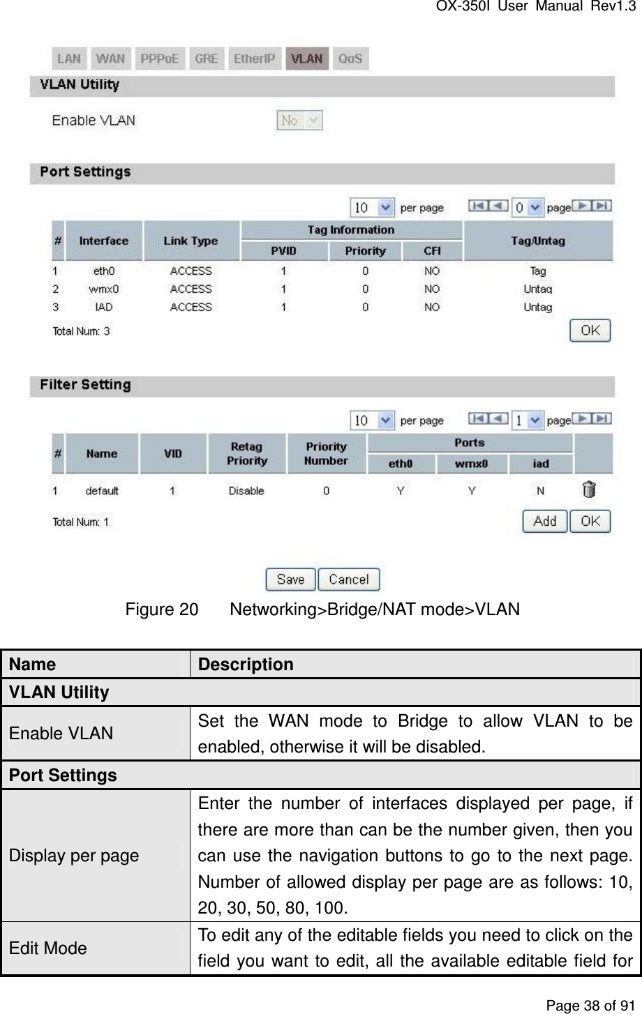
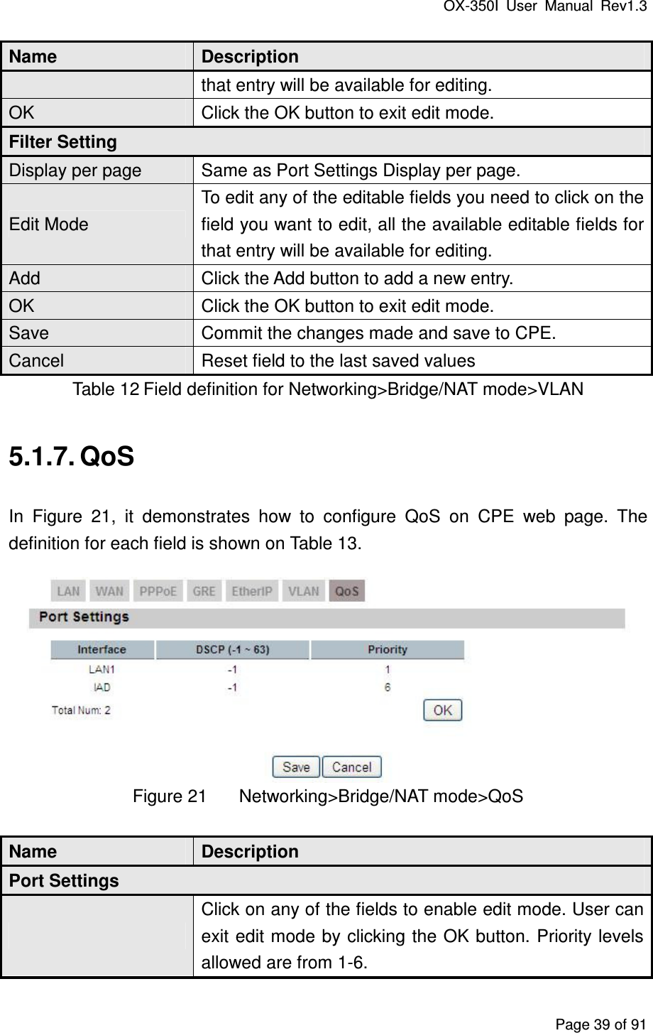
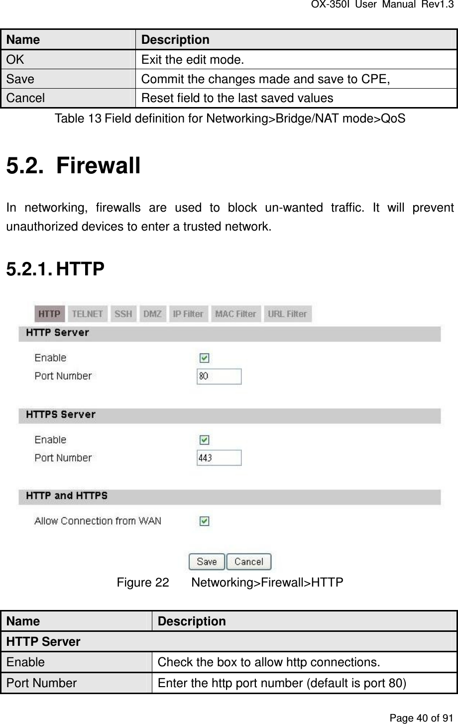
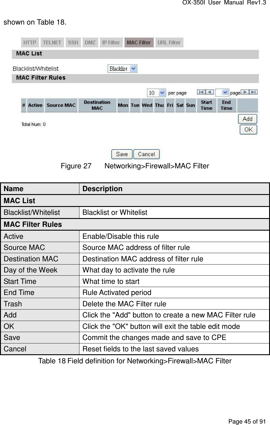
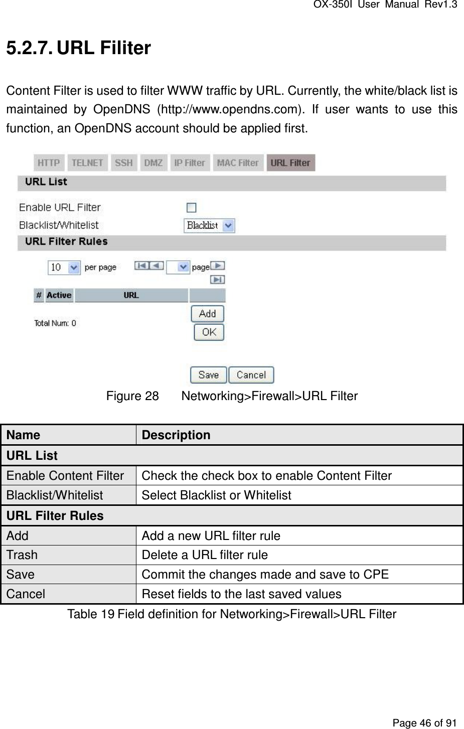
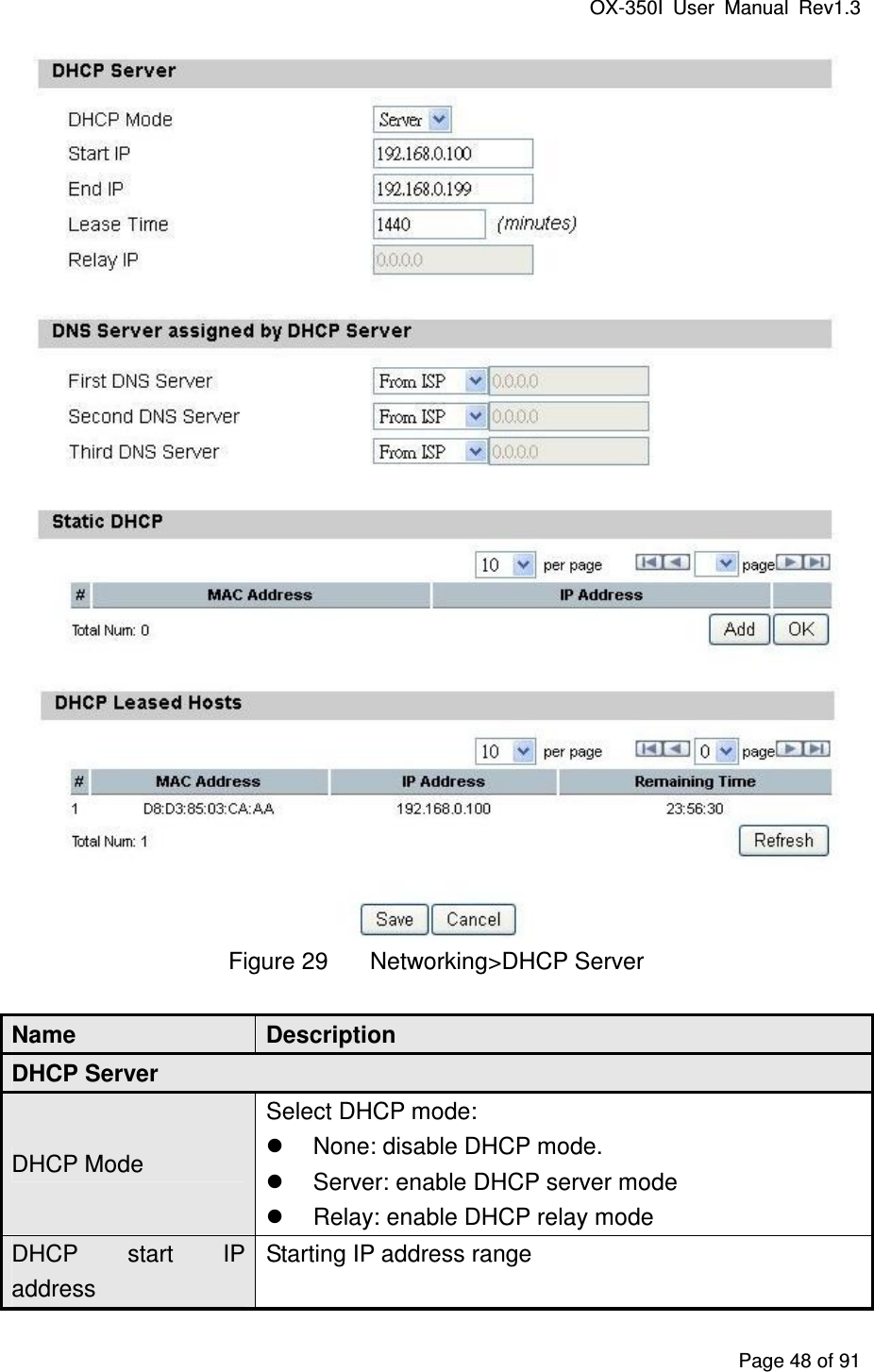
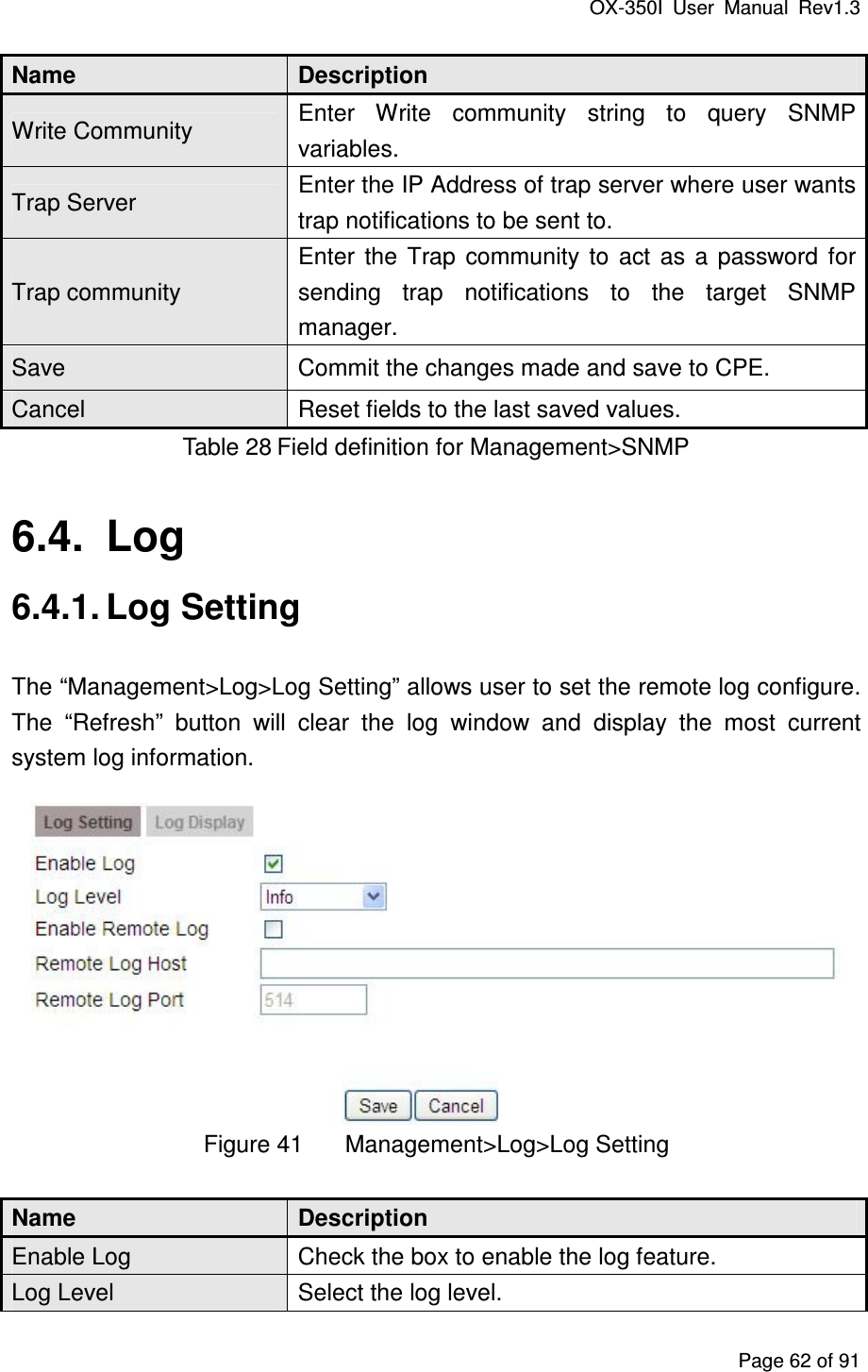
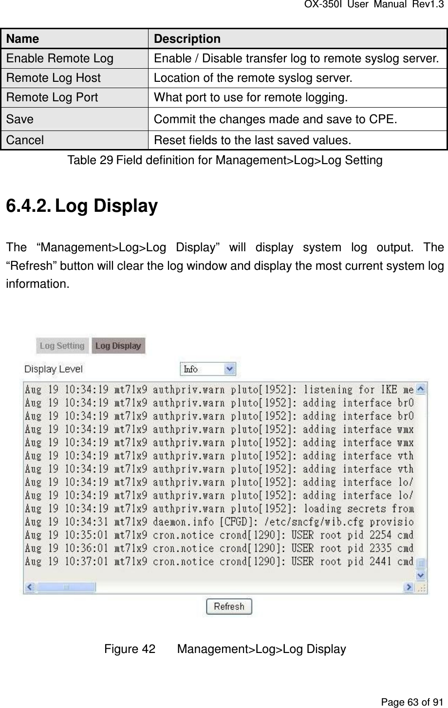
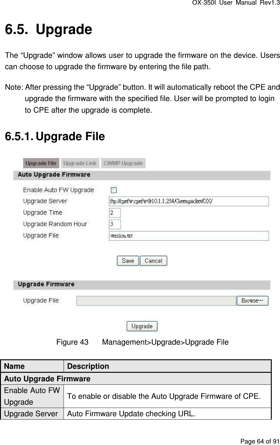
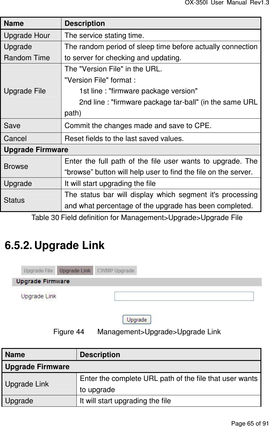
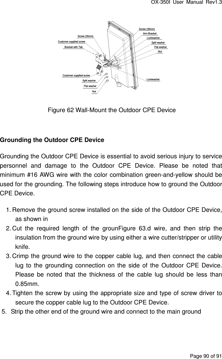
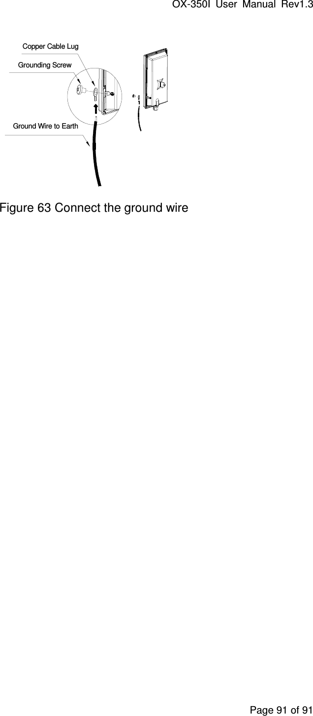
UM