Green Packet Berhad OX350I-GP WiMAX Outdoor CPE User Manual rev1
Green Packet Berhad, Taiwan WiMAX Outdoor CPE rev1
Contents
- 1. User manual rev1
- 2. UM
User manual rev1
Page 1 of 91
User Manual
OX-350I
WiMAX Outdoor CPE
Version: 1.2
Date: Oct. 04, 2011

OX-350I User Manual Rev1.2
Page 2 of 91
Previous History
Revision
Date of Issue
Scope
Author
1.0 2011/08/31 Initial document Alpha C.
1.1 2011/09/21 Add FCC Warning Wording Tony Kao
1.2 2011/10/04 Modify Important Notice content in page 4 Tony Kao
OX-350I User Manual Rev1.2
Page 3 of 91
Federal Communication Commission Interference Statement :
This equipment has been tested and found to comply with the limits for a Class B
digital device, pursuant to Part 15 of the FCC Rules. These limits are designed
to provide reasonable protection against harmful interference in a residential
installation. This equipment generates, uses and can radiate radio frequency
energy and, if not installed and used in accordance with the instructions, may
cause harmful interference to radio communications. However, there is no
guarantee that interference will not occur in a particular installation. If this
equipment does cause harmful interference to radio or television reception, which
can be determined by turning the equipment off and on, the user is encouraged to
try to correct the interference by one of the following measures:
- Reorient or relocate the receiving antenna.
- Increase the separation between the equipment and receiver.
- Connect the equipment into an outlet on a circuit different from that to which
the receiver is connected.
- Consult the dealer or an experienced radio/TV technician for help.
FCC Caution: Any changes or modifications not expressly approved by the party
responsible for compliance could void the user's authority to operate this
equipment.
This device complies with Part 15 of the FCC Rules. Operation is subject to the
following two conditions: (1) This device may not cause harmful interference, and
(2) this device must accept any interference received, including interference that
may cause undesired operation.
OX-350I User Manual Rev1.2
Page 4 of 91
FCC Radiation Exposure Statement:
This equipment complies with FCC radiation exposure limits set forth for an
uncontrolled environment. This equipment should be installed and operated with
minimum distance 60cm between the radiator & your body.
This transmitter must not be co-located or operating in conjunction with any other
antenna or transmitter.
Due to the essential high output power natural of WiMAX device, use of this
device with other transmitter at the same time may exceed the FCC RF exposure
limit and such usage must be prohibited (unless such co-transmission has been
approved by FCC in the future).
IMPORTANT NOTE:
According to FCC regulation (FCC 05-56), in order for the device to
safely operate in the 3.675~3.700 GHz range, the device shall be connected
to a Base station which supports "listen mode" and can instruct this device
accordingly.
OX-350I User Manual Rev1.2
Page 5 of 91
Table of Contents
Previous History ............................................................................................... 2
1. Introduction ............................................................................................. 16
1.1. Connect ........................................................................................ 16
1.2. Logout .......................................................................................... 17
2. Status ...................................................................................................... 18
2.1. WiMAX Status .............................................................................. 18
2.2. Network Status ............................................................................. 18
2.3. Device Status ............................................................................... 19
3. Personalization ....................................................................................... 20
3.1. Account ........................................................................................ 20
3.2. Date ............................................................................................. 21
3.2.1. Date ................................................................................... 22
3.2.2. Time Zone ......................................................................... 23
4. WiMAX .................................................................................................... 24
4.1. Scanner ........................................................................................ 24
4.2. Authentication .............................................................................. 26
4.3. Wide Scan .................................................................................... 29
5. Networking .............................................................................................. 31
5.1. Bridge/NAT mode ......................................................................... 31
OX-350I User Manual Rev1.2
Page 6 of 91
5.1.1. LAN ................................................................................... 31
5.1.2. WAN .................................................................................. 32
5.1.3. PPPoE ............................................................................... 34
5.1.4. GRE .................................................................................. 36
5.1.5. EtherIP .............................................................................. 37
5.1.6. VLAN ................................................................................. 37
5.1.7. QoS ................................................................................... 39
5.2. Firewall ......................................................................................... 40
5.2.1. HTTP ................................................................................. 40
5.2.2. TELNET ............................................................................ 41
5.2.3. SSH ................................................................................... 42
5.2.4. DMZ .................................................................................. 42
5.2.5. IP Filiter ............................................................................. 43
5.2.6. MAC Filiter......................................................................... 44
5.2.7. URL Filiter ......................................................................... 46
5.3. DHCP Server ............................................................................... 47
5.4. NAT ALG ...................................................................................... 50
5.5. Forwarding ................................................................................... 51
5.6. Trigger .......................................................................................... 52
5.7. DDNS ........................................................................................... 54
OX-350I User Manual Rev1.2
Page 7 of 91
5.8. UPnP ............................................................................................ 56
5.9. Ping .............................................................................................. 57
6. Management ........................................................................................... 58
6.1. TR-069 ......................................................................................... 58
6.2. OMA-DM ...................................................................................... 59
6.3. SNMP ........................................................................................... 61
6.4. Log ............................................................................................... 62
6.4.1. Log Setting ........................................................................ 62
6.4.2. Log Display ....................................................................... 63
6.5. Upgrade ....................................................................................... 64
6.5.1. Upgrade File ...................................................................... 64
6.5.2. Upgrade Link ..................................................................... 65
6.5.3. CWMP Upgrade ................................................................ 66
6.6. Recovery ...................................................................................... 66
6.6.1. Backup .............................................................................. 67
6.6.2. Restore .............................................................................. 69
6.6.3. Factory Defaults ................................................................ 70
7. VPN ........................................................................................................ 71
7.1. PPTP ............................................................................................ 71
7.1.1. PPTP Server ..................................................................... 71
OX-350I User Manual Rev1.2
Page 8 of 91
7.1.2. PPTP Client ....................................................................... 74
7.2. L2TP ............................................................................................ 75
7.2.1. L2TP Server ...................................................................... 76
7.2.2. L2TP Client ........................................................................ 79
7.3. IPsec ............................................................................................ 81
8. Quick Installation Guide ........................................... 錯誤
錯誤錯誤
錯誤! 尚未定義書籤
尚未定義書籤尚未定義書籤
尚未定義書籤。
。。
。
OX-350I User Manual Rev1.2
Page 9 of 91
List of Figures
Figure 1 Login ............................................................................................ 17
Figure 2 Logout ......................................................................................... 17
Figure 3 Status>WiMAX Status .................................................................. 18
Figure 4 Status>Network Status ................................................................ 19
Figure 5 Status>Device Status................................................................... 19
Figure 6 Personalization>Account ............................................................. 20
Figure 7 Personalization>Date>Date ......................................................... 22
Figure 8 Personalization>Date>Time Zone ............................................... 23
Figure 9 Wireless Broadband Access ........................................................ 24
Figure 10 WiMAX>Scanner ..................................................................... 25
Figure 11 WiMAX>Authentication(No authentication) .............................. 26
Figure 12 WiMAX>Authentication(User authentication) ........................... 28
Figure 13 WiMAX>Wide Scan.................................................................. 30
Figure 14 Network Topology .................................................................... 31
Figure 15 Networking>Bridge/NAT mode>LAN ........................................ 31
Figure 16 Networking>Bridge/NAT mode>WAN ...................................... 32
Figure 17 Networking>Bridge/NAT mode>PPPoE ................................... 35
Figure 18 Networking>Bridge/NAT mode>GRE ....................................... 36
Figure 19 Networking>Bridge/NAT mode>EtherIP ................................... 37
OX-350I User Manual Rev1.2
Page 10 of 91
Figure 20 Networking>Bridge/NAT mode>VLAN ..................................... 38
Figure 21 Networking>Bridge/NAT mode>QoS........................................ 39
Figure 22 Networking>Firewall>HTTP ..................................................... 40
Figure 23 Networking>Firewall>TELNET ................................................. 41
Figure 24 Networking>Firewall>SSH ....................................................... 42
Figure 25 Networking>Firewall>DMZ ....................................................... 43
Figure 26 Networking>Firewall>IP Filter .................................................. 43
Figure 27 Networking>Firewall>MAC Filter .............................................. 45
Figure 28 Networking>Firewall>URL Filter .............................................. 46
Figure 29 Networking>DHCP Server ....................................................... 48
Figure 30 Networking>NAT ALG .............................................................. 50
Figure 31 Networking>Forwarding ........................................................... 51
Figure 32 Networking>Forwarding>Wizard .............................................. 51
Figure 33 Networking>Trigger .................................................................. 53
Figure 34 Networking>Trigger>Wizard .................................................... 53
Figure 35 Networking>DDNS ................................................................... 55
Figure 36 Networking>UPnP ................................................................... 56
Figure 37 Networking>Ping ...................................................................... 57
Figure 38 Management>TR-069 .............................................................. 58
Figure 39 Management>OMA-DM ........................................................... 60
OX-350I User Manual Rev1.2
Page 11 of 91
Figure 40 Management>SNMP................................................................ 61
Figure 41 Management>Log>Log Setting ................................................ 62
Figure 42 Management>Log>Log Display ............................................... 63
Figure 43 Management>Upgrade>Upgrade File ...................................... 64
Figure 44 Management>Upgrade>Upgrade Link ..................................... 65
Figure 45 Management>Upgrade>CWMP Upgrade ................................ 66
Figure 46 Management>Recovery>Backup ............................................. 67
Figure 47 File Download .......................................................................... 67
Figure 48 Save File As ............................................................................. 68
Figure 49 Management>Recovery>Restore ............................................ 69
Figure 50 Management>Recovery>Factory Defaults ............................... 70
Figure 51 Restore to factory reset warning .............................................. 70
Figure 52 VPN>PPTP>PPTP Server ....................................................... 72
Figure 53 VPN>PPTP>PPTP Client ......................................................... 74
Figure 54 VPN>PPTP>PPTP Client>Add ................................................ 74
Figure 55 VPN>L2TP>L2TP Server ......................................................... 77
Figure 56 VPN>L2TP>L2TP Client .......................................................... 79
Figure 57 VPN>L2TP>L2TP Client>Add .................................................. 80
Figure 58 VPN>IPsec Overview............................................................... 81
Figure 59 VPN>IPsec>Add ...................................................................... 83
OX-350I User Manual Rev1.2
Page 12 of 91
Figure 60 Mounting accessory list ................................................................. 87
Figure 61 Pole-Mount the Outdoor CPE Device ............................................ 89
Figure 62 Wall-Mount the Outdoor CPE Device ............................................ 90
Figure 63 Connect the ground wire ............................................................... 91
OX-350I User Manual Rev1.2
Page 13 of 91
List of Tables
Table 1 Field definition for Personalization>Account ................................ 21
Table 2 Field definition for Personalization>Date>Date ........................... 23
Table 3 Field definition for Personalization>Date>Time Zone .................. 23
Table 4 Field definition for WiMAX>Scanner ............................................ 26
Table 5 Field definition for WiMAX>Authentication................................... 29
Table 6 Field definition for WiMAX>Wide Scan ........................................ 30
Table 7 Field definition for Networking>Bridge/NAT mode>LAN .............. 32
Table 8 Field definition for Networking>Bridge/NAT mode>WAN ............. 34
Table 9 Field definition for Networking>Bridge/NAT mode>PPPoE.......... 36
Table 10 Field definition for Networking>Bridge/NAT mode>GRE ............. 37
Table 11 Field definition for Networking>Bridge/NAT mode>EtherIP ......... 37
Table 12 Field definition for Networking>Bridge/NAT mode>VLAN ............ 39
Table 13 Field definition for Networking>Bridge/NAT mode>QoS .............. 40
Table 14 Field definition for Networking>Firewall>HTTP ........................... 41
Table 15 Field definition for Networking>Firewall>TELNET ....................... 42
Table 16 Field definition for Networking>Firewall>SSH ............................. 42
Table 17 Field definition for Networking>Firewall>IP Filter ......................... 44
Table 18 Field definition for Networking>Firewall>MAC Filter .................... 45
Table 19 Field definition for Networking>Firewall>URL Filter ..................... 46
OX-350I User Manual Rev1.2
Page 14 of 91
Table 20 Field definition for Networking>DHCP Server .............................. 50
Table 21 Field definition for Networking>Forwarding ................................. 52
Table 22 Field definition for Networking>Trigger ........................................ 54
Table 23 Field definition for Networking>DDNS ......................................... 56
Table 24 Field definition for Networking>UPnP .......................................... 57
Table 25 Field definition for Networking>Ping ............................................ 57
Table 26 Field definition for Management>TR-069 .................................... 59
Table 27 Field definition for Management>OMA-DM ................................. 61
Table 28 Field definition for Management>SNMP ...................................... 62
Table 29 Field definition for Management>Log>Log Setting ...................... 63
Table 30 Field definition for Management>Upgrade>Upgrade File ............ 65
Table 31 Field definition for Management>Upgrade>Upgrade Link ........... 66
Table 32 Field definition for Management>Upgrade>CWMP Upgrade ...... 66
Table 33 Field definition for Management>Recovery>Backup ................... 68
Table 34 Field definition for Management>Recovery>Restore................... 69
Table 35 Field definition for VPN>PPTP>PPTP Server.............................. 74
Table 36 Field definition for VPN>PPTP>PPTP Client ............................... 75
Table 37 Field definition for VPN>L2TP>L2TP Server ............................... 79
Table 38 Field definition for VPN>L2TP>L2TP Client ................................ 81
Table 39 Field definition for VPN>IPsec>Add ............................................ 86
OX-350I User Manual Rev1.2
Page 15 of 91
OX-350I User Manual Rev1.2
Page 16 of 91
1. Introduction
The CPE Software platform comes with a Web-based Configuration Manager,
which gives users the ability to manage, configure and analyze the platforms
environment. The Connection Manager works with all versions of Windows after
Windows 95.
The supported browser version:
Internet Explorer Ver 8.06001 or later (Recommended)
FireFox Ver.3.6.3 and higher
Google Chrome Ver.5.0.375.125 and higher
Opera Ver.9.64 and higher
Safari Ver.4.05 and higher
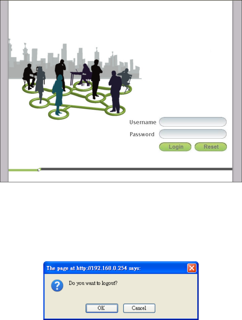
1.1. Connect
Users need to connect to the CPE platform. It’s assumed that the user has a fully
working CPE platform and properly connected. From the web browser connect to
the device, entering the IP address of the device; it will prompt user to enter the
username and password. The default IP address, usernames and passwords are
as follows.
Default IP Address
192.168.0.254
Username/Password
admin/admin
guest/guest
OX-350I User Manual Rev1.2
Page 17 of 91
Figure 1 Login
1.2. Logout
The “Logout” window allows users to disconnect from the device and exit the
Web-based Configuration Manager.
Figure 2 Logout
OX-350I User Manual Rev1.2
Page 18 of 91
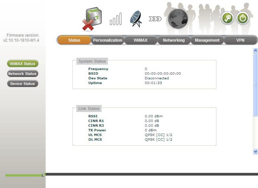
2. Status
After user has established a connection, user will see the “Status” window. It gives
user an initial overview of the current status of the device.
2.1. WiMAX Status
This window shows the information of system status, WiMAX link status and
service flow status.
Figure 3 Status>WiMAX Status
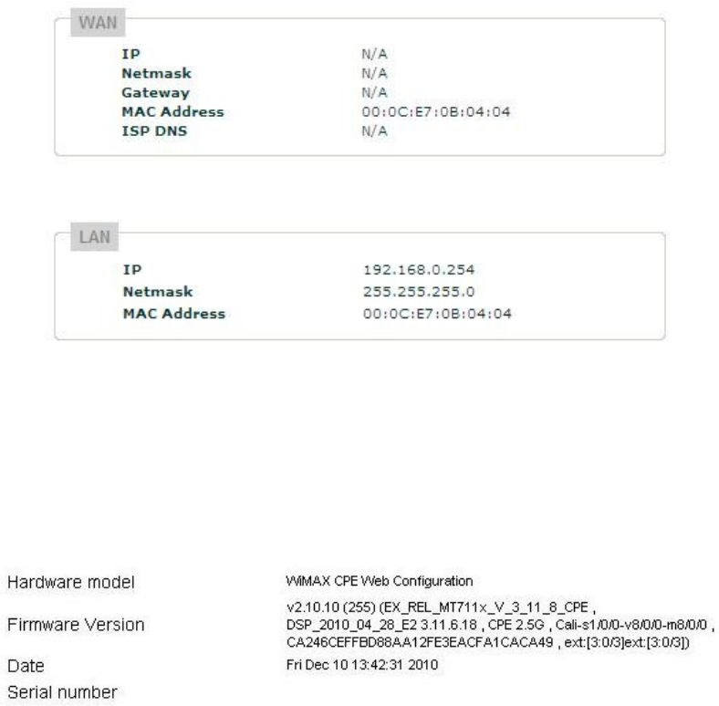
2.2. Network Status
This window shows the information of WAN status and LAN status.
OX-350I User Manual Rev1.2
Page 19 of 91
Figure 4 Status>Network Status
2.3. Device Status
This window shows the information of device status.
Figure 5 Status>Device Status
OX-350I User Manual Rev1.2
Page 20 of 91
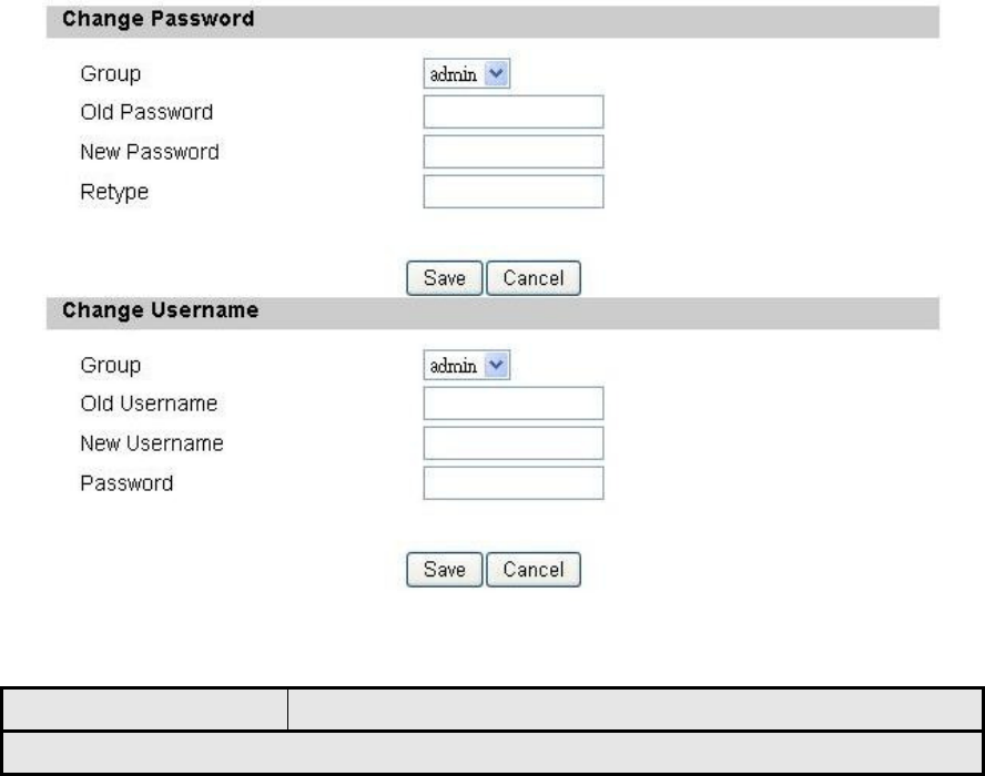
3. Personalization
3.1. Account
Note: The default usernames and passwords are admin/admin and guest/guest.
The user with administrative privileges (belonging to the “admin” group) has
access to all the features in the software. A user with “guest” privileges (belonging
to the “guest” group) only has a subset of the features available to them.
Note: There can only be one username in each of the groups (one to one
relationship).
Figure 6 Personalization>Account
Name Description
Change Password

OX-350I User Manual Rev1.2
Page 21 of 91
Group
Select which group the user belongs to that user would
like to change the password for.
admin, if the user is part of the admin group, they
have full access to all the features.
guest, if the user is part of the guest group, they
have limited access to the features.
Old Password Enter the old password.
New Password Enter the new password.
Retype Retype the new password.
Save Commit the changes made and save to CPE, it will only
commit the change made to the password.
Cancel Reset fields to the last saved values.
Change Username
Group
Select which group the user belongs to that user would
like to change the username for.
admin, if the user is part of the admin group, they
have full access to the features.
guest, if the user is part of the guest group, they
have limited access to the features.
Old Username Enter the username user wants to change.
New Username Enter the new username.
Password
Enter the original password, the password will not
change. If user enter an incorrect or different password
the change will not be committed
Save Commit the changes made and save to CPE, it will only
commit the change made to the username.
Cancel Reset fields to the last saved values.
Table 1 Field definition for Personalization>Account
3.2. Date
User can configure the date and time on the device. The user can manually
configure the system time, or choose to get the date and time from a time server.
The “Save” button will commit the configuration, and the “Cancel” button will clear
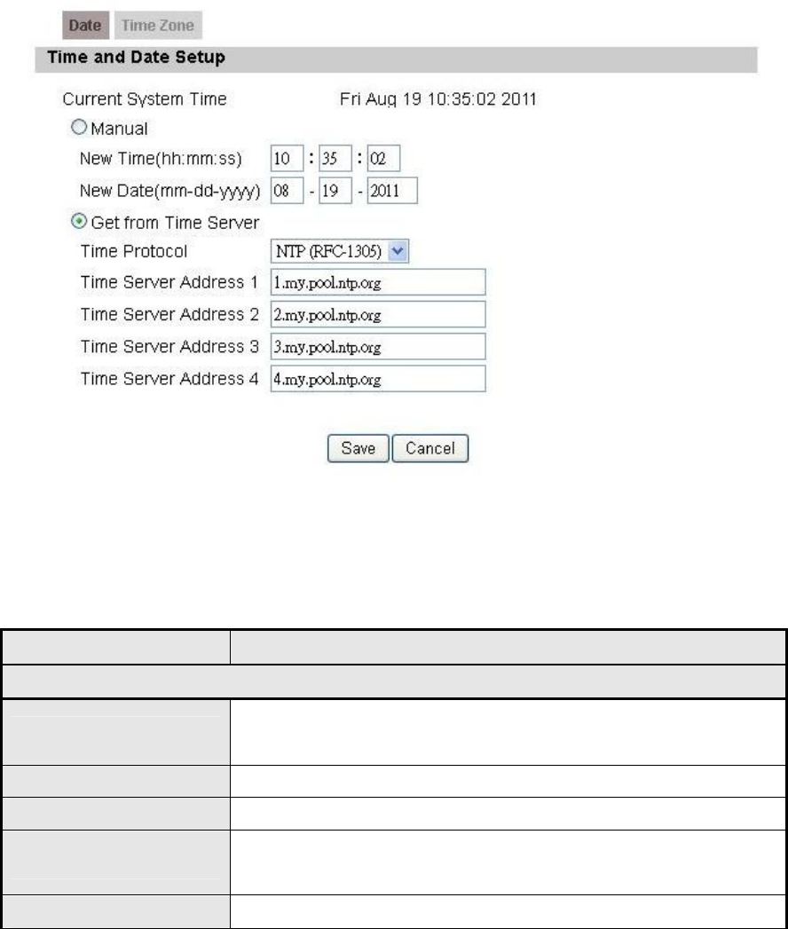
OX-350I User Manual Rev1.2
Page 22 of 91
the fields. The “Time Zone” tab will allow user to set the time zone and set the
starting and finish time for daylight saving period. User can also enable or disable
“Daylight Savings Time”.
Note: If user doesn’t configure the time on the CPE it will use the default system
starting time which is set to 1970/1/1 00:00:00
Figure 7 Personalization>Date>Date
3.2.1. Date
Name Description
Time and Date Setup
Manual If user selects the Manual option, then user needs to
enter the time and date manually.
New Time New time manually entered
New Date New date manually entered
Get From Time Server
If user selects this option it will get the local time from a
time server automatically.
Time Protocol Select the Time protocol
OX-350I User Manual Rev1.2
Page 23 of 91
Name Description
Time Server Address Enter the address of the time server.
Save Commit the changes made and save to CPE
Cancel Reset fields to the last saved values
Table 2 Field definition for Personalization>Date>Date
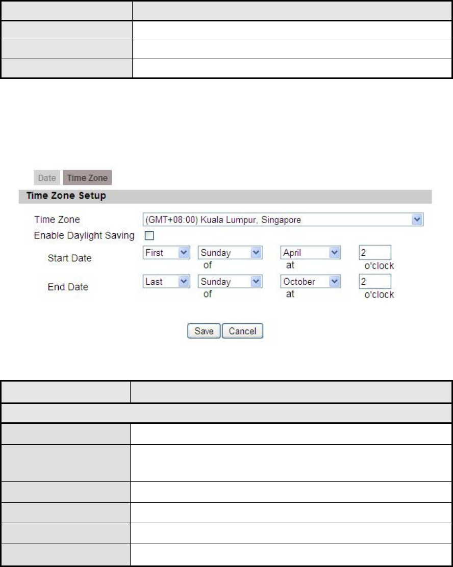
3.2.2. Time Zone
Figure 8 Personalization>Date>Time Zone
Name Description
Time Zone Setup
Time Zone Enter the time zone of for the location
Enable Daylight
Savings
If user wants to enable Daylight Savings Time, user
needs to check the box.
Start Date Enter the beginning date for Daylight Savings time
End Date Enter the end date for Daylight Savings time.
Save Commit the changes made and save to CPE
Cancel Reset fields to the last saved values
Table 3 Field definition for Personalization>Date>Time Zone
OX-350I User Manual Rev1.2
Page 24 of 91
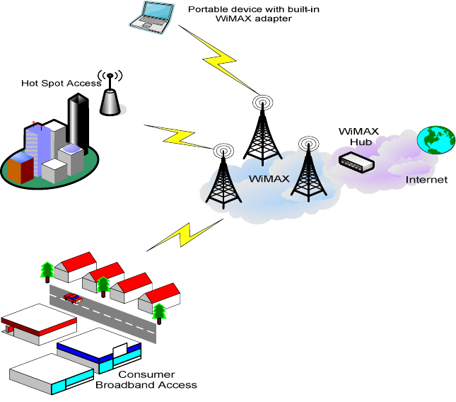
4. WiMAX
This technology is based on the IEEE 802.16 standard, enabling the delivery of
last mile wireless broadband access.
Figure 9 Wireless Broadband Access
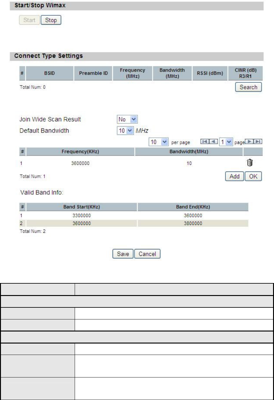
4.1. Scanner
The user can set WiMAX standard settings, which include how to establish a
connection and get frequency information.
The frequency list window will display all the configured frequencies and their
bandwidth. To set additional frequencies, click on the “Add” button.
OX-350I User Manual Rev1.2
Page 25 of 91
Figure 10 WiMAX>Scanner
Name Description
Start/Stop Wimax
Start Click the “Start” button to connect to a BSID
Stop Click the “Stop” button to terminate the connection
Connect Type Settings
Search Click the “Search” button to scan the frequency
Joint Wide Scan
Result
Yes means to append wide scan result to the frequency
setting.
Default Bandwidth Select the default bandwidth to be used in Frequency List
5 MHz
OX-350I User Manual Rev1.2
Page 26 of 91
Name Description
7 MHz
10 MHz
Valid Band Info
Valid band information. If the frequencies aren’t located
using the valid band range, the frequency setting will be
rejected.
Add The "Add" button will allow user to enter more frequency
lists
OK Click the "OK" button to exit table edit mode
Save Commit the changes made and save to CPE
Cancel Reset fields to the last saved values
Table 4 Field definition for WiMAX>Scanner
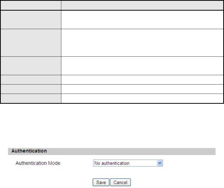
4.2. Authentication
Figure 11 WiMAX>Authentication(No authentication)
OX-350I User Manual Rev1.2
Page 27 of 91

OX-350I User Manual Rev1.2
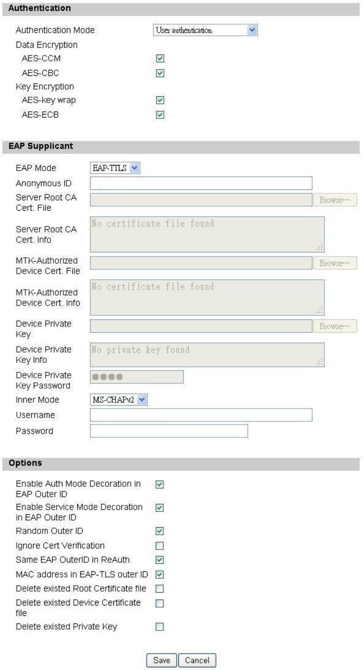
Page 28 of 91
Figure 12 WiMAX>Authentication(User authentication)
Name Description
Authentication
Authentication Mode
The method used in authentication.
No Authentication
User Authentication
Device Authentication
User and Device Authentication
Data Encryption AES-CCM
Enable MS’s capability of encrypting/decrypting
traffic by AES-CCM.
Data Encryption AES-CBC
Enable MS's capability of encrypting/decrypting
traffic by AES-CBC.
Key Encryption AES-key
wrap
Enable MS's capability of decrypting TEK by
AES-Key wrap.
Key Encryption AES-ECB Enable MS's capability of decrypting TEK by
AES-ECB.
EAP Supplicant
EAP Mode The EAP method used in authentication
Anonymous ID The identity encoded in EAP Identity Response
message. User needs to fill the Outer ID at this field.
Server Root CA Cert. File The root CA's X.509 certificate.
Server Root CA Cert. Info The root CA's certificate information.
MTK-Authorized Device
Cert. File The MS's X.509 certificate.
MTK-Authorized Device
Cert. Info The root MS's certificate information.
Device Private Key The MS's private key file corresponding to the public
key enhanced in x.509 certificate
Device Private Key Info The MS's private key information.
Device Private Key
Password The key used to decrypt the MS’s private key file
Inner Mode The EAP-TTLS inner method

OX-350I User Manual Rev1.2
Page 29 of 91
Name Description
User name The user name used in EAP-TTLS inner method
Password The password used in EAP-TTLS inner method.
Options
Enable Auth Mode
Decoration in EAP Outer
ID
puts {am=i} in EAP outer ID
i = 1: user authentication
i = 2: device authentication
i = 3: user & device authentication
Enable Service Mode
Decoration in EAP Outer
ID
puts {sm=1} in EAP outer ID
Random Outer ID
Enable MS to generate 16-bytes random number as
the user name in the EAP Identity Response
message.
Ignore Cert Verification MS skips to verify the BS's certificate received in the
EAP-TLS or EAP-TTLS procedure.
Same EAP Outer ID in
ReAuth Use the same EAP outer ID when doing re-auth
MAC address in EAP-TLS
outer ID
Add MAC address in outer ID when EAP mode is
EAP-TLS
Delete existed Root
Certificate file Remove the files loaded from UI
Delete existed Device
Certificate file
Delete device certificate file which was uploaded in
the field “MTK-authorized Device Certificate”
Delete existed Private Key
Delete device private key which was uploaded in the
field “Device Private Key”
Save Commit the changes made and save to CPE
Cancel Reset fields to the last saved values
Table 5 Field definition for WiMAX>Authentication
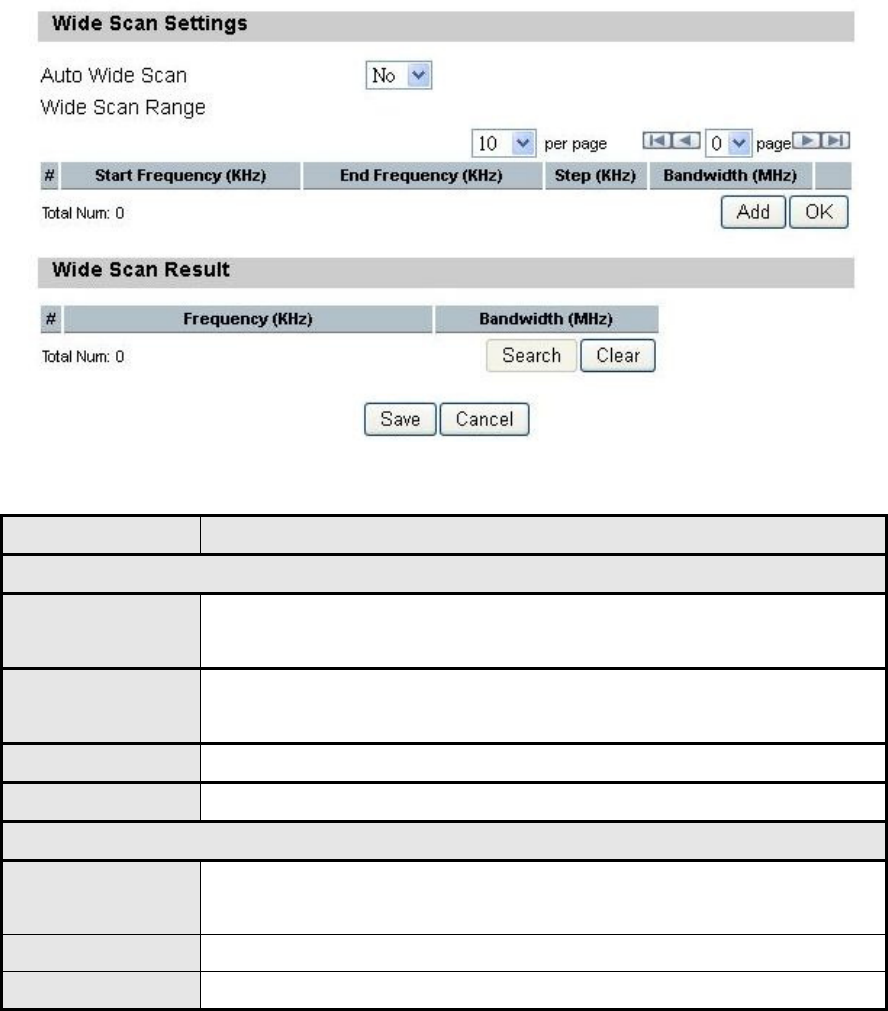
4.3. Wide Scan
The “Wide Scan” function is used for scanning BS based on scanning rule. User
OX-350I User Manual Rev1.2
Page 30 of 91
can set the scan rule with defining start, stop frequency, step, and channel
bandwidth, and CPE will base on this rule to scan the BS as shown in Figure 13.
The definition for each field is shown on Table 6.
Figure 13 WiMAX>Wide Scan
Name Description
Wide Scan Settings
Auto Wide Scan
Select “Yes” to do “wide scan” automatically when there are no
available BS
Wide Scan
Range User can specify the wide scan range to reduce search time
Add Click the "Add" button to create a new wide scan range
OK Click the "OK" button will exit the table edit mode
Wide Scan Result
Search Show the result of wide scan. Search button can trigger wide
scan
Clear Clear button clear current search result
Save/Cancel Save/Cancel current setting
Table 6 Field definition for WiMAX>Wide Scan
OX-350I User Manual Rev1.2
Page 31 of 91
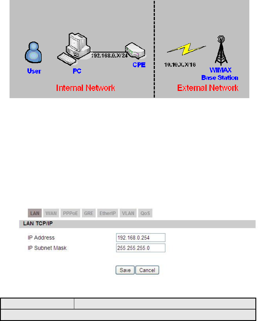
5. Networking
Refer to Figure 14 for proper network connection.
Figure 14 Network Topology
5.1. Bridge/NAT mode
5.1.1. LAN
From the “Networking>Bridge/NAT mode>LAN” window, user can update the LAN
information as shown in Figure 15. The definition for each field is shown on Table
7.
Figure 15 Networking>Bridge/NAT mode>LAN
Name Description
LAN TCP/IP
OX-350I User Manual Rev1.2
Page 32 of 91
Name Description
IP Address IP address of CPE
IP Subnet Mask Subnet Mask of CPE
Save Commits the changes made, and set the LAN IP
information, some services will be reloaded.
Cancel Reset the fields to the last saved values
Table 7 Field definition for Networking>Bridge/NAT mode>LAN
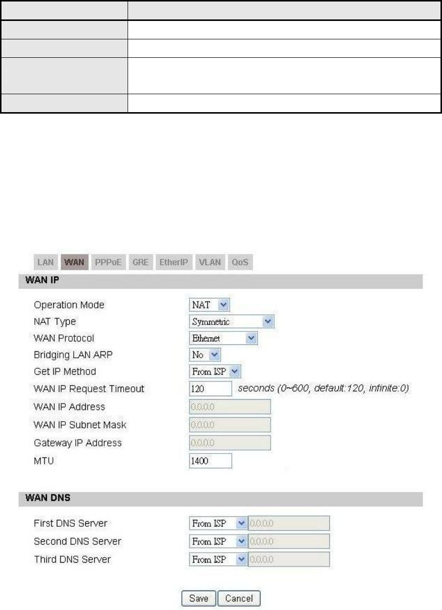
5.1.2. WAN
In Figure 16, it demonstrates how to configure WAN settings on CPE web page.
The definition for each field is shown on Table 8.
Figure 16 Networking>Bridge/NAT mode>WAN

OX-350I User Manual Rev1.2
Page 33 of 91
Name
Description
WAN IP
Operation Mode
Select the WAN operation mode
Bridge
Routing
NAT
NAT Type
Select the NAT Type
Symmetric,
Full cone,
Restricted cone,
Port-Restricted cone,
WAN Protocol
Select the WAN encapsulation protocol
Ethernet
PPPoE
GRE Tunnel
EtherIP Tunnel
Bridging LAN ARP
Allow Bridging LAN ARP
Yes
No
Get IP Method
Select the IP method
From ISP
User
WAN IP Request
Timeout
The time the DHCP client waits to receive the IP
address from the BS. If it doesn’t get the IP, it will
timeout and the CPE will disconnect the WiMAX
connection. The default value is 120 seconds. If user
enters 0, it will wait to receive the IP address infinitely
until it’s stopped by the user.
WAN IP Address If user chooses “Static” for IP Method, user should enter
the WAN IP address
WIN IP Subnet Mask If user chooses “Static” for IP Method, user should enter
the WAN IP subnet mask.
Gateway IP Address If user chooses “Static” for IP Method, user should enter
IP gateway address
MTU Enter the MTU

OX-350I User Manual Rev1.2
Page 34 of 91
Name
Description
WAN DNS
First DNS Server
Second DNS Server
Third DNS Server
User can specify three DNS servers and select how the
DNS Server is assigned. There are three options for
assigning the DNS server.
From ISP
User Defined
If user selects “User Define”, user needs to enter a valid
IP address for the DNS server.
Save
Commit the changes made and save to CPE, after
clicking the Save button user will get a message asking
if user wants to reboot the CPE. Reboot is necessary for
the device to switch to a different profile.
Cancel Reset field to the last saved values
Table 8 Field definition for Networking>Bridge/NAT mode>WAN
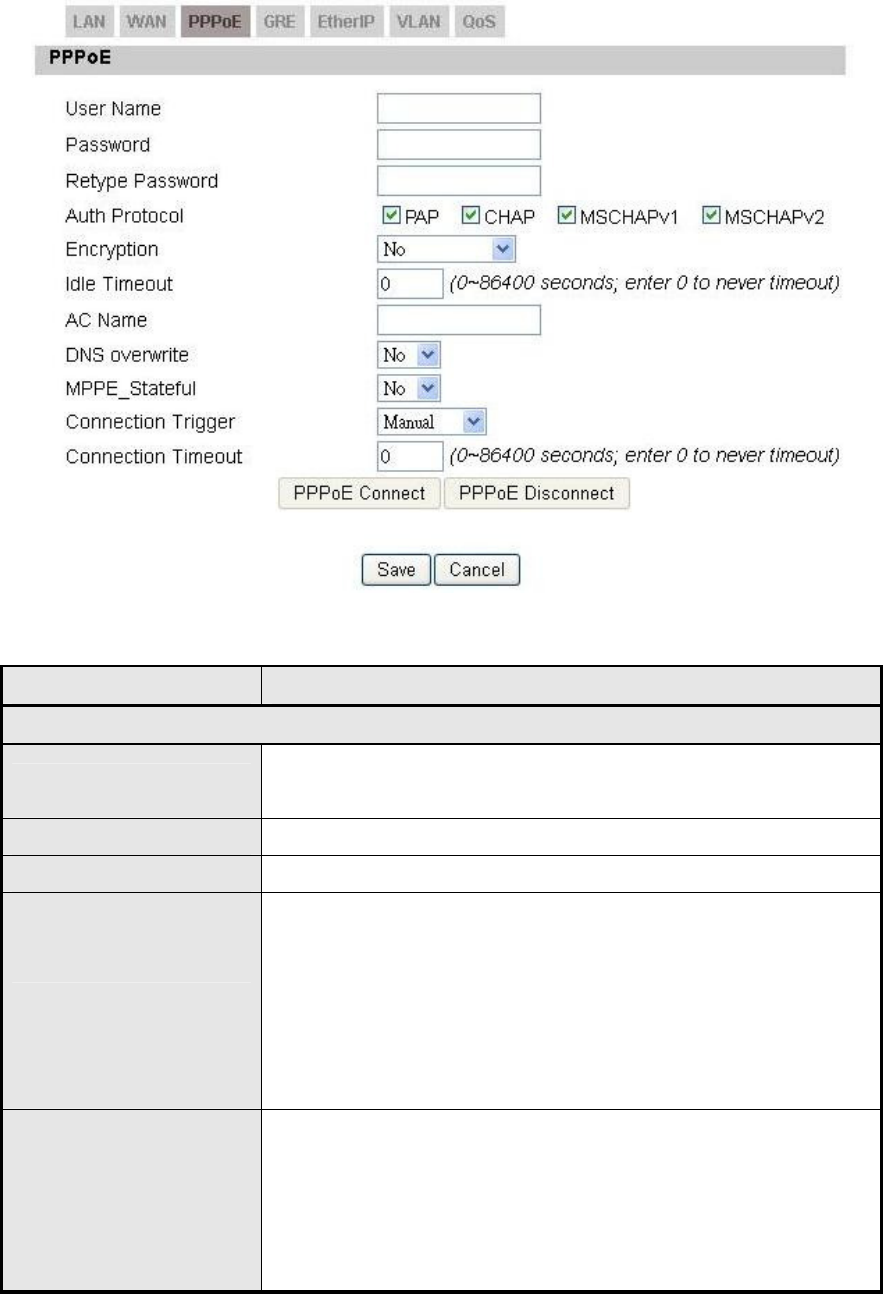
5.1.3. PPPoE
In Figure 17, it demonstrates how to configure PPPoE on CPE web page. The
definition for each field is shown on Table 9.
OX-350I User Manual Rev1.2
Page 35 of 91
Figure 17 Networking>Bridge/NAT mode>PPPoE
Name Description
PPPoE
User Name The user name to connect PPPoE server via the
selected Auth Protocol
Password The password of the corresponding username
Retype Password Type the “Password” again
Auth Protocol
The authentication protocol of the peer required. Select
which Authentication protocol to use.
PAP
CHAP
MSCHAPv1
MSCHAPv2
Encryption
Encryption Scheme
No
MPPE 40 bits: 40-bit encryption with MPPE
MPPE 128 bits: 128-bit encryption with MPPE
Auto: automatically selected

OX-350I User Manual Rev1.2
Page 36 of 91
Name Description
Idle Timeout Disconnect if the link is idle for the assigned seconds
AC Name The name of the access concentrator to connection to
DNS Overwrite
Yes
No
MPPE_Stateful
Yes
No
Connection Trigger
Always On
Manual
Connection Timeout Time to attempt to connect, if connection attempt fails
after that time it will halt attempting to connect
Save
Commit the changes made and save to CPE, after
clicking the Save button user will get a message asking
if user wants to reboot the CPE. Reboot is necessary for
the device to switch to a different profile.
Cancel Reset field to the last saved values
Table 9 Field definition for Networking>Bridge/NAT mode>PPPoE
5.1.4. GRE
In Figure 18, it demonstrates how to configure GRE on CPE web page. The
definition for each field is shown on Table 9.
Figure 18 Networking>Bridge/NAT mode>GRE
Name Description
GRE Peer
Peer IP Address Enter the IP address of its GRE Peer
OX-350I User Manual Rev1.2
Page 37 of 91
Name Description
Save Commit the changes made and save to CPE
Cancel Reset fields to the last saved values
Table 10 Field definition for Networking>Bridge/NAT mode>GRE
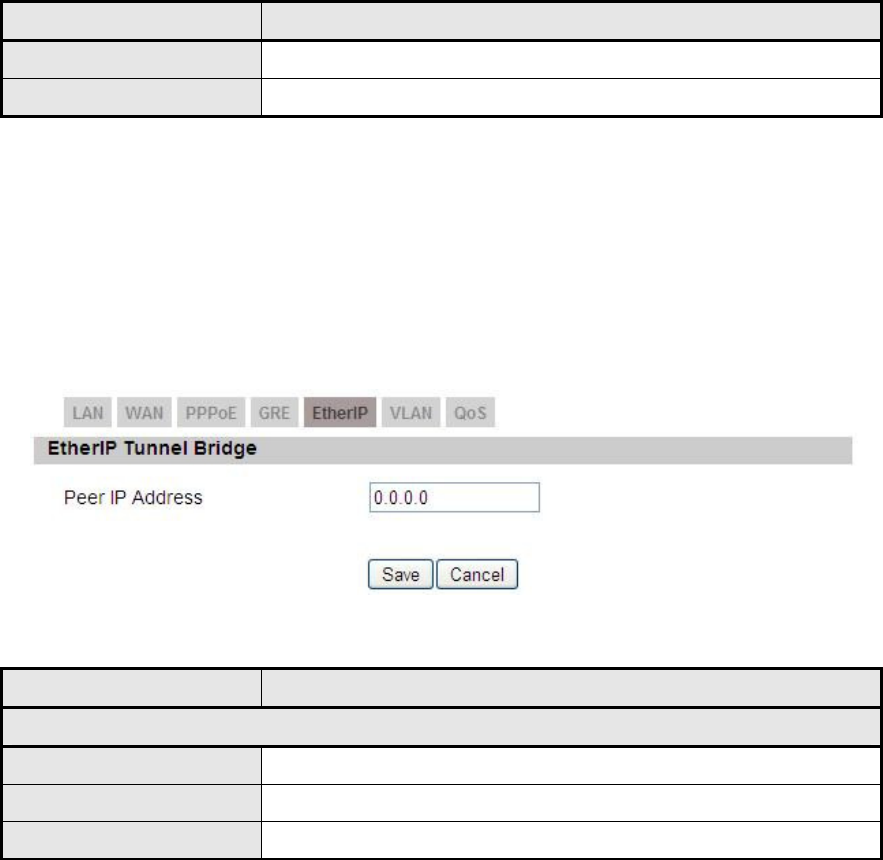
5.1.5. EtherIP
In Figure 19, it demonstrates how to configure EtherIP on CPE web page. The
definition for each field is shown on Table 9.
Figure 19 Networking>Bridge/NAT mode>EtherIP
Name Description
EtherIP Tunnel Bridge
Peer IP Address Enter the IP address of its EtherIP Peer
Save Commit the changes made and save to CPE
Cancel Reset fields to the last saved values
Table 11 Field definition for Networking>Bridge/NAT mode>EtherIP
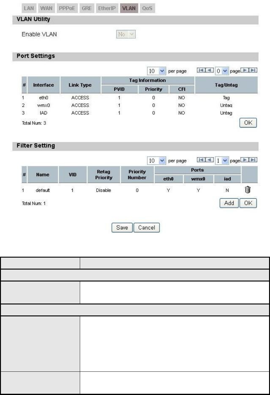
5.1.6. VLAN
In Figure 20Figure 17, it demonstrates how to configure VLAN on CPE web page.
The definition for each field is shown on Table 12.
OX-350I User Manual Rev1.2
Page 38 of 91
Figure 20 Networking>Bridge/NAT mode>VLAN
Name Description
VLAN Utility
Enable VLAN Set the WAN mode to Bridge to allow VLAN to be
enabled, otherwise it will be disabled.
Port Settings
Display per page
Enter the number of interfaces displayed per page, if
there are more than can be the number given, then you
can use the navigation buttons to go to the next page.
Number of allowed display per page are as follows: 10,
20, 30, 50, 80, 100.
Edit Mode To edit any of the editable fields you need to click on the
field you want to edit, all the available editable field for
OX-350I User Manual Rev1.2
Page 39 of 91
Name Description
that entry will be available for editing.
OK Click the OK button to exit edit mode.
Filter Setting
Display per page Same as Port Settings Display per page.
Edit Mode
To edit any of the editable fields you need to click on the
field you want to edit, all the available editable fields for
that entry will be available for editing.
Add Click the Add button to add a new entry.
OK Click the OK button to exit edit mode.
Save Commit the changes made and save to CPE.
Cancel Reset field to the last saved values
Table 12 Field definition for Networking>Bridge/NAT mode>VLAN
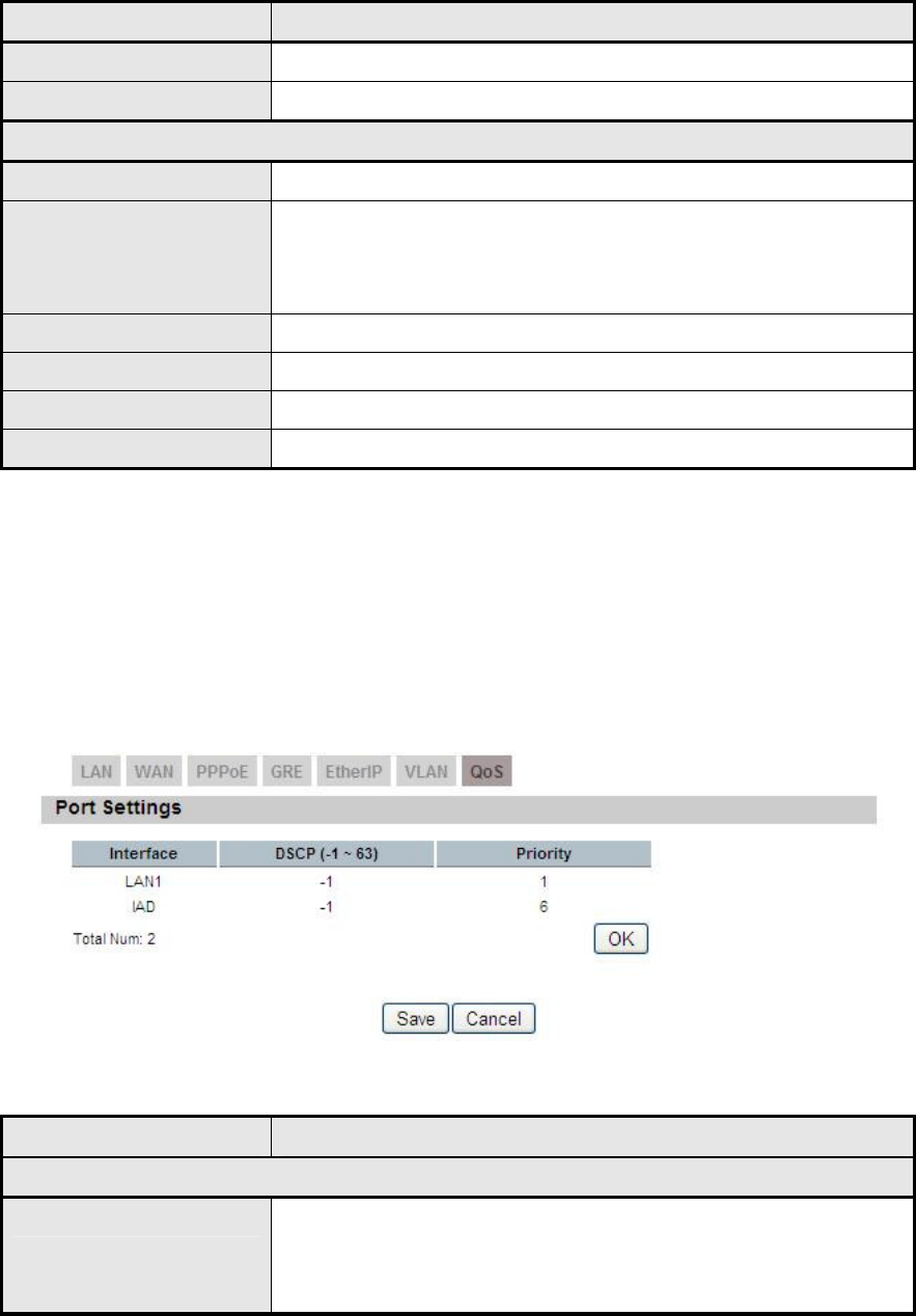
5.1.7. QoS
In Figure 21, it demonstrates how to configure QoS on CPE web page. The
definition for each field is shown on Table 13.
Figure 21 Networking>Bridge/NAT mode>QoS
Name Description
Port Settings
Click on any of the fields to enable edit mode. User can
exit edit mode by clicking the OK button. Priority levels
allowed are from 1-6.
OX-350I User Manual Rev1.2
Page 40 of 91
Name Description
OK Exit the edit mode.
Save Commit the changes made and save to CPE,
Cancel Reset field to the last saved values
Table 13 Field definition for Networking>Bridge/NAT mode>QoS
5.2. Firewall
In networking, firewalls are used to block un-wanted traffic. It will prevent
unauthorized devices to enter a trusted network.
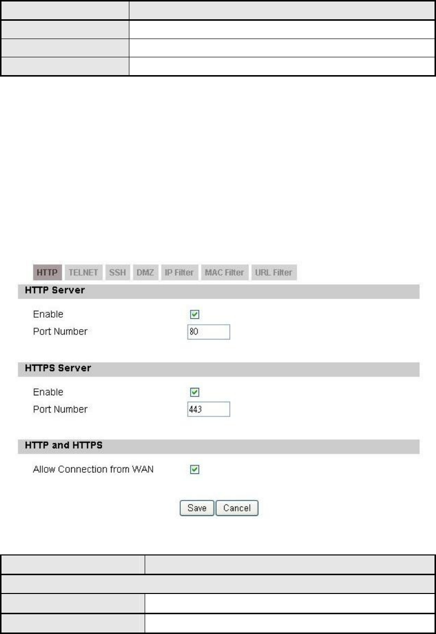
5.2.1. HTTP
Figure 22 Networking>Firewall>HTTP
Name Description
HTTP Server
Enable Check the box to allow http connections.
Port Number Enter the http port number (default is port 80)
OX-350I User Manual Rev1.2
Page 41 of 91
Name Description
HTTPS Server
Enable Check the box to allow https connections.
Port Number Enter the https port number (default is port 443)
HTTP and HTTPS
Allow Connection from
WAN Check the check-box to allow connections from WAN.
Save Commit the changes made and save to CPE.
Cancel Reset fields to the last saved values.
Table 14 Field definition for Networking>Firewall>HTTP
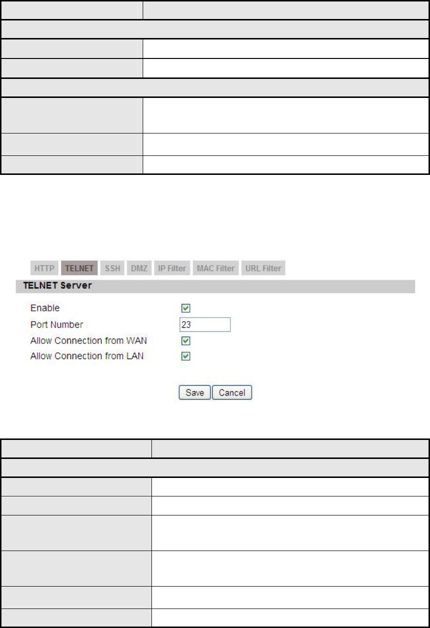
5.2.2. TELNET
Figure 23 Networking>Firewall>TELNET
Name Description
TELNET Server
Enable Check the box to allow Telnet connections.
Port Number Enter the Telnet port number (default is port 23)
Allow Connection from
WAN
Check the check-box to allow connections from
WAN.
Allow Connection from
LAN
Check the check-box to allow connections from
LAN.
Save Commit the changes made and save to CPE.
Cancel Reset fields to the last saved values.
OX-350I User Manual Rev1.2
Page 42 of 91
Table 15 Field definition for Networking>Firewall>TELNET
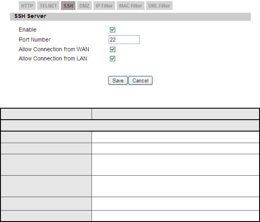
5.2.3. SSH
Figure 24 Networking>Firewall>SSH
Name Description
SSH Server
Enable Check the box to allow SSH connections.
Port Number Enter the SSH port (default is port 22)
Allow Connection from
WAN
Check the check-box to allow connections from
WAN.
Allow Connection from
LAN
Check the check-box to allow connections from
LAN.
Save Commit the changes made and save to CPE.
Cancel Reset fields to the last saved values.
Table 16 Field definition for Networking>Firewall>SSH
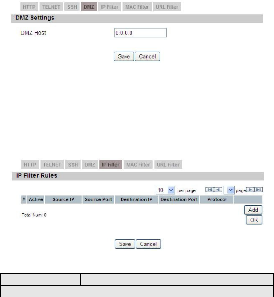
5.2.4. DMZ
DMZ stands for Demilitarized Zone. It is a physical or logical sub-network that
contains and exposes an organization's external services to a larger un-trusted
network, usually the Internet. The term is normally referred to as a DMZ by IT
professionals. It is sometimes referred to as a Perimeter Network. The purpose of
a DMZ is to add an additional layer of security to an organization's LAN; an
OX-350I User Manual Rev1.2
Page 43 of 91
external attacker only has access to equipment in the DMZ, rather than any other
part of the network.
The “Networking>Firewall>DMZ” tab allows user to configure a DMZ host IP
address as shown in Figure 25. In DMZ Settings, user needs to enter the IP
address of the DMZ host. The “Save” button will save the changes to CPE and the
“Cancel” button will reset the field to last saved value. It will disable DMZ host
when entering “0.0.0.0”.
Figure 25 Networking>Firewall>DMZ
5.2.5. IP Filiter
The IP filter rules will drop or discard traffic that fits the filter criteria. User can
define IP filter rules as shown in Figure 26. The definition for each field is shown
on Table 17.
Figure 26 Networking>Firewall>IP Filter
Name Description
IP Filter Rules

OX-350I User Manual Rev1.2
Page 44 of 91
Name Description
Add Click the "Add" button to create a new IP Filter rule
OK Click the "OK" button will exit the table edit mode
Active Check the box to activate the IP Filter rule
Source IP Source IP to filter on. It can be in one of the following
formats:
IP address (ex. 192.168.0.222)
Subnet (ex. 192.168.1.0/24)
IP range (ex. 192.168.0.150~192.168.0.160)
0.0.0.0/0 means any
Source Port Source Port to filter on. It can be one of the following
formats:
Port number (ex. 8080)
Port Range (ex. 1024~2048)
Destination IP Destination IP to filter on. It can be in one of the following
formats:
IP address (ex. 192.168.0.222)
Subnet (ex. 192.168.1.0/24)
IP range (ex. 192.168.0.150~192.168.0.160)
0.0.0.0/0 means any
Destination Port Destination port to filter on. It can be one of the following
formats:
Port number (ex. 8080)
Port Range (ex. 1024~2048)
Protocol Protocol to filter on
Trash Delete the IP Filter rule
Save Commit the changes made and save to CPE
Cancel Reset fields to the last saved values
Table 17 Field definition for Networking>Firewall>IP Filter
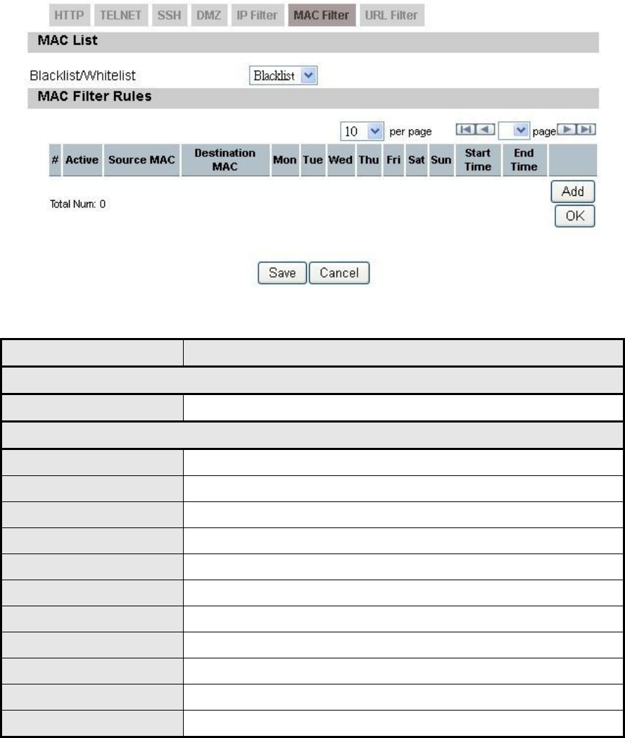
5.2.6. MAC Filiter
The MAC filter rules will drop or discard traffic that the filter criteria. User can
define MAC filter rules as shown in Figure 27. The definition for each field is
OX-350I User Manual Rev1.2
Page 45 of 91
shown on Table 18.
Figure 27 Networking>Firewall>MAC Filter
Name Description
MAC List
Blacklist/Whitelist Blacklist or Whitelist
MAC Filter Rules
Active Enable/Disable this rule
Source MAC Source MAC address of filter rule
Destination MAC Destination MAC address of filter rule
Day of the Week What day to activate the rule
Start Time What time to start
End Time Rule Activated period
Trash Delete the MAC Filter rule
Add Click the "Add" button to create a new MAC Filter rule
OK Click the "OK" button will exit the table edit mode
Save Commit the changes made and save to CPE
Cancel Reset fields to the last saved values
Table 18 Field definition for Networking>Firewall>MAC Filter
OX-350I User Manual Rev1.2
Page 46 of 91
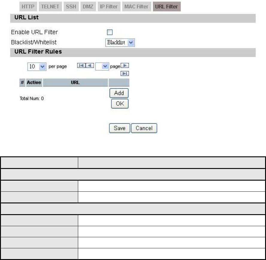
5.2.7. URL Filiter
Content Filter is used to filter WWW traffic by URL. Currently, the white/black list is
maintained by OpenDNS (http://www.opendns.com). If user wants to use this
function, an OpenDNS account should be applied first.
Figure 28 Networking>Firewall>URL Filter
Name Description
URL List
Enable Content Filter Check the check box to enable Content Filter
Blacklist/Whitelist Select Blacklist or Whitelist
URL Filter Rules
Add Add a new URL filter rule
Trash Delete a URL filter rule
Save Commit the changes made and save to CPE
Cancel Reset fields to the last saved values
Table 19 Field definition for Networking>Firewall>URL Filter
OX-350I User Manual Rev1.2
Page 47 of 91
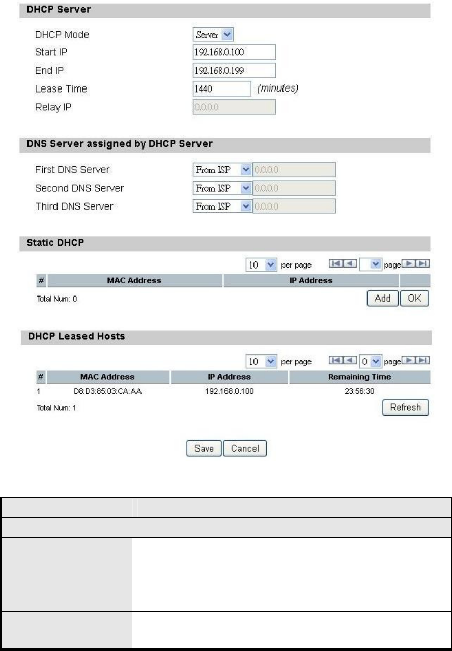
5.3. DHCP Server
Use the “Networking> DHCP Server” tab to configure the DHCP server
information. The default DHCP Server setup is enabled, and user could disable
this function from setup as shown in Figure 29. When user disables the DHCP
server, it requires setting a static IP address on host PC for CPE to configure.
Please be noted that without the static IP address set properly on the host PC,
user can not open the CPE web page for configuration.
When DHCP server is enabled, user needs to define the IP pool range for
dynamically assigning the IP address. The advantage of using DHCP server is
that the addresses which are no longer in use will be returned to the IP address
pool so that the server can reallocate them to other machines in the network.
There are three DNS servers the user can configure to assign an IP address.
Static DHCP will assign an IP address on the LAN to a specific device based on
its MAC address. The definition for each field is shown on Table 20.
OX-350I User Manual Rev1.2
Page 48 of 91
Figure 29 Networking>DHCP Server
Name Description
DHCP Server
DHCP Mode
Select DHCP mode:
None: disable DHCP mode.
Server: enable DHCP server mode
Relay: enable DHCP relay mode
DHCP start IP
address
Starting IP address range

OX-350I User Manual Rev1.2
Page 49 of 91
Name Description
DHCP end IP address
Ending IP address range
Lease Time
The lease time is a controlled time period, allowing the
DHCP server to reclaim (and then reallocate) IP
addresses that are not renewed (dynamic re-use of IP
addresses). Lease time is measured in minutes in the
Configuration Manager.
Relay IP Enter the IP address of DHCP relay.
DNS Server assigned by DHCP Server
First DNS Server
Second DNS Server
Third DNS Server
User can specify three DNS servers and select how the
DNS Server is assigned. There are three options for
assigning the DNS server.
From ISP
User Defined
None
If user selects “None”, then the DHCP server will not give
clients the DNS server information. If all the three DNS
servers setting are set to “None”, then the DHCP server
will use the LAN IP address as the DNS server
information for the clients. If the user chooses “User
Defined” and leaves the IP address as “0.0.0.0” it will
change the field to “None”.
Static DHCP
Static DHCP Enter MAC address and IP address for static DHCP
addresses.
Add
Click on the “Add” button to enter a static leased IP
address. Enter the MAC address of the Ethernet device
and enter the IP address.
OK Click the “OK” button to exit out of edit mode.
DHCP Leased Hosts
DHCP Leased Hosts List of Leased IP addresses. The “Refresh” button will
display an updated list of leased addresses.
Save Commit the changes made and save to CPE, some
services will be reloaded.
Cancel Reset fields to the last saved values.
OX-350I User Manual Rev1.2
Page 50 of 91
Table 20 Field definition for Networking>DHCP Server
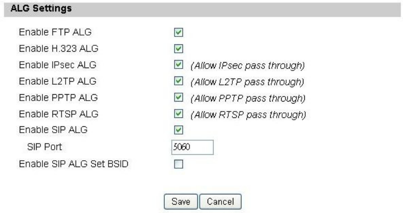
5.4. NAT ALG
There are some ALG settings that user can enable from “Networking>NAT ALG”.
ALG allows legitimate application traffic to pass through the CPE that would have
otherwise restricted. Without ALGs, some application may not work well because
of NAT/firewall settings. User could click on the check box to enable ALGs.
Note: If user is using any of these types of application protocols user needs to
enable them in the ALG settings.
FTP ALG
H.323 ALG
IPsec ALG
L2TP ALG
PPTP ALG
RTSP ALG
SIP ALG
SIP Port
SIP ALG Set BSID
Figure 30 Networking>NAT ALG
OX-350I User Manual Rev1.2
Page 51 of 91
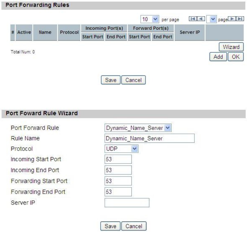
5.5. Forwarding
Forwarding is the act of forwarding the data from WAN side to the particular port
of the private IP. This function can allow remote computers to reach a port on a
private IP address within a private LAN. In the following, it will introduce how to
setup for Port Forward. First, user needs to click the “Add” button and then select
which forward type, TCP or UDP or TCP/UDP, is preferred to trigger the special
application as shown in Figure 31 and Figure 32. User needs to assign some
specific port for the WAN IP to be forwarded to the defined LAN IP and port, and
then click the “Save” button to add a Port Forward rule. The definition for each
field is shown on Table 21.
Figure 31 Networking>Forwarding
Figure 32 Networking>Forwarding>Wizard

OX-350I User Manual Rev1.2
Page 52 of 91
Name Description
Port Forwarding Rules
Active Check the box to active the port forward rule
Name Name of the port forward rule
Protocol User needs to define the desired protocol for rule.
Available options are: TCP, UDP, or TCP/UDP
Incoming Port(s) User needs to define incoming port range for port
forwarding rule.
Forward Port(s)
User needs to define to which port range will be
translated for port forwarding rule. The packet will be
forwarded to one of these ports if it matches the rule.
Server IP
User needs to define which IP address will be translated
to if it matches the Port Forwarding rule. The packet will
be forwarded to this IP address if it matches the rule.
Trash Delete the Port Forward rule
Wizard Click the ”Wizard” button to go to the Port Forward Rule
Wizard
Add Click the “Add” button to create a new Port Forward rule
OK Click the “OK” button to exit table edit mode
Save Commit the changes made and save to the CPE
Cancel Reset field to the last saved values.
Table 21 Field definition for Networking>Forwarding
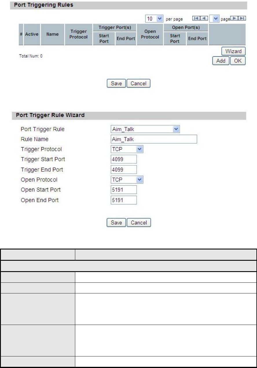
5.6. Trigger
The “Networking>Trigger” allows user to configure Port Trigger rules. Port Trigger
is a way to automate port forwarding in which outbound traffic on predetermined
ports (‘trigger port’) causes inbound traffic to specific incoming ports to be
dynamically forwarded to the initiating host, while the outbound ports are in use.
This allows users behind CPE on the LAN to provide services that would normally
require the computer to have IP address on the LAN. Port triggering triggers an
open incoming port (‘open port’) when a client on the local network makes an
outgoing connection on a predetermined port or range of ports. The definition for
each field is shown on Table 22.
OX-350I User Manual Rev1.2
Page 53 of 91
Figure 33 Networking>Trigger
Figure 34 Networking>Trigger>Wizard
Name Description
Port Triggering Rules
Active Check the box to active the Port Trigger rule
Name Name of the Port Trigger rule
Trigger Protocol
It defines which protocol the outgoing packet used will
trigger the rule. Available options are TCP, UDP or
TCP/UDP
Trigger Port(s)
It defines which port range the outgoing packet will
trigger the rule. User needs to enter the starting and
ending port range
Open Protocol It defines which protocol will be opened if the rule had

OX-350I User Manual Rev1.2
Page 54 of 91
Name Description
been triggered. Available options are TCP, UDP or
TCP/UDP
Open Port(s)
It defines which protocol port will be opened if the rule
had been triggered. User needs to enter the starting and
ending port range
Trash Delete the Port Trigger rule
Wizard Click the ”Wizard” button to go to the Port Trigger Rule
Wizard
Add Click the “Add” button to enter a Port Trigger rule
OK Click the “OK” button to exit, table edit mode.
Save Commit the changes made and save to the CPE
Cancel Reset fields to the last saved values
Table 22 Field definition for Networking>Trigger
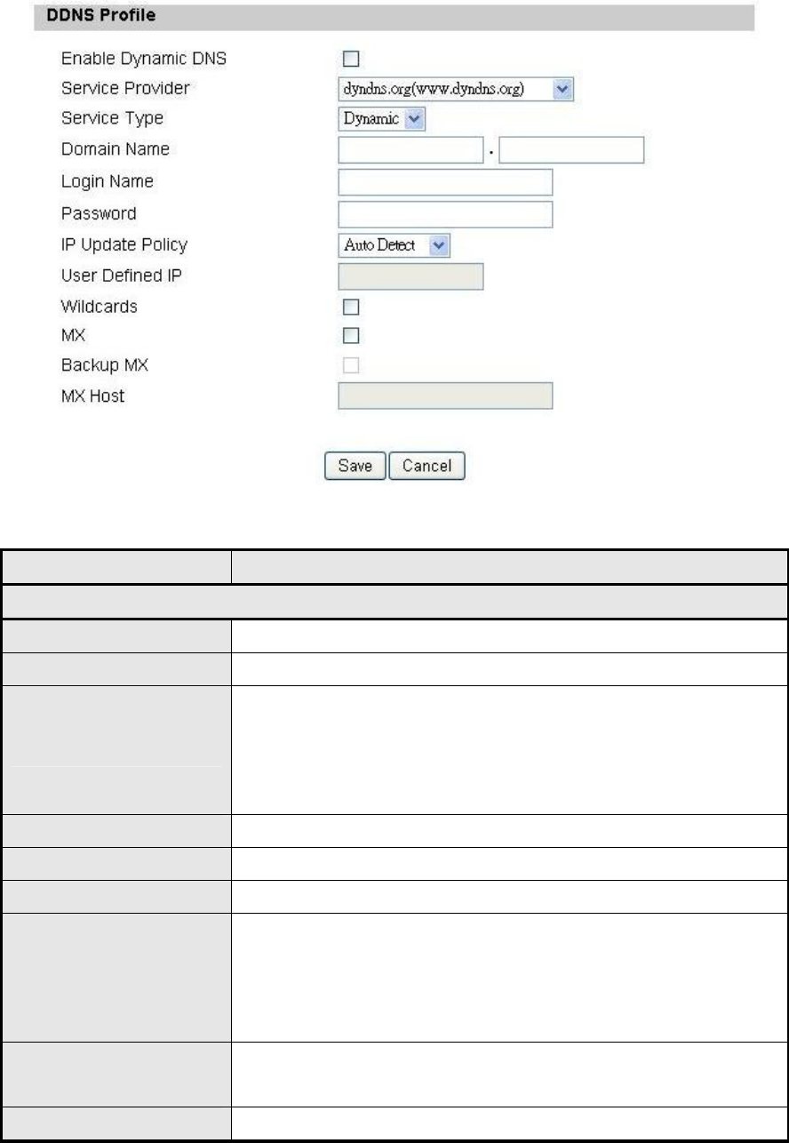
5.7. DDNS
DDNS stands for Dynamic Domain Name Services. It provides a function to
convert the domain name to the unique IP address. With DDNS, users is able to
find and connect to CPE no matter what IP address CPE is currently using, that is,
DDNS can map CPE's dynamic IP address to a static hostname. The best profit of
this function allows user to access CPE from everywhere.
In Figure 35, it demonstrates how to configure DDNS on CPE web page. The
definition for each field is shown on Table 23.
OX-350I User Manual Rev1.2
Page 55 of 91
Figure 35 Networking>DDNS
Name Description
DDNS Profile
Enable Dynamic DNS
Click the check box to enable dynamic DNS
Service Provider Enter the URL of the Service Provider
Service Type*
Enter the service type (DYNDNS only)
Dynamic
Static
Custom
Domain Name Enter the domain name
Login Name Enter the username
Password Enter the password
IP Update Policy
Select the Policy to be used
Auto Detect
WAN IP
User Defined
User Defined IP If user selects “User Defined” as the IP policy, user has to
enter the IP address.
Wildcards* Allow hostname to use wildcards such as “*”. It will allow
OX-350I User Manual Rev1.2
Page 56 of 91
Name Description
“*host.dyndns.org” to be aliased to the same IP address
as “host.hyndns.org”
MX* Enable mail routing
Backup MX* Enable Second mail routing
MX Host* Host that mail will be routed to
Save Commit the changes made and save to CPE
Cancel Reset fields to the last saved values
Note: * Supported by DYNDNS service provider.
Table 23 Field definition for Networking>DDNS
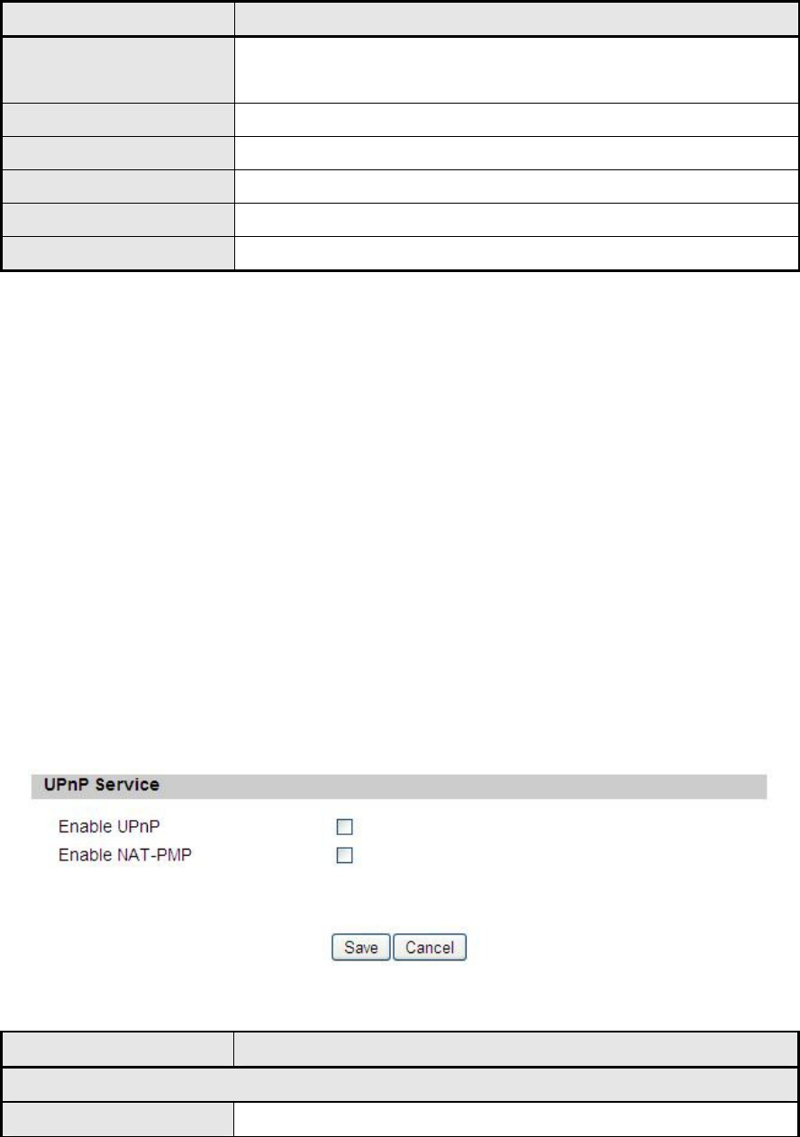
5.8. UPnP
Two methods of simplifying the process of connecting a device to the network are
available as shown in Figure 36. UPnP allows devices to connect seamlessly to
networks in the home (data sharing, communications, and entertainment) and in
corporate environments for simplified installation of computer components. NAT
Port Mapping Protocol (NAP-PMP) allows a computer in a private network (behind
a NAT router) to automatically configure the router to allow parties outside the
private network to contact itself. The definition for each field of UPnP Setting is
shown on Table 24.
Figure 36 Networking>UPnP
Name Description
UPnP Service
Enable UPnP Check the check box to enable UPnP
OX-350I User Manual Rev1.2
Page 57 of 91
Name Description
Enable NAT-PMP Check the check box to enable NAT-PMP
Save Commit the changes made and save to CPE
Cancel Reset fields to the last saved values
Table 24 Field definition for Networking>UPnP
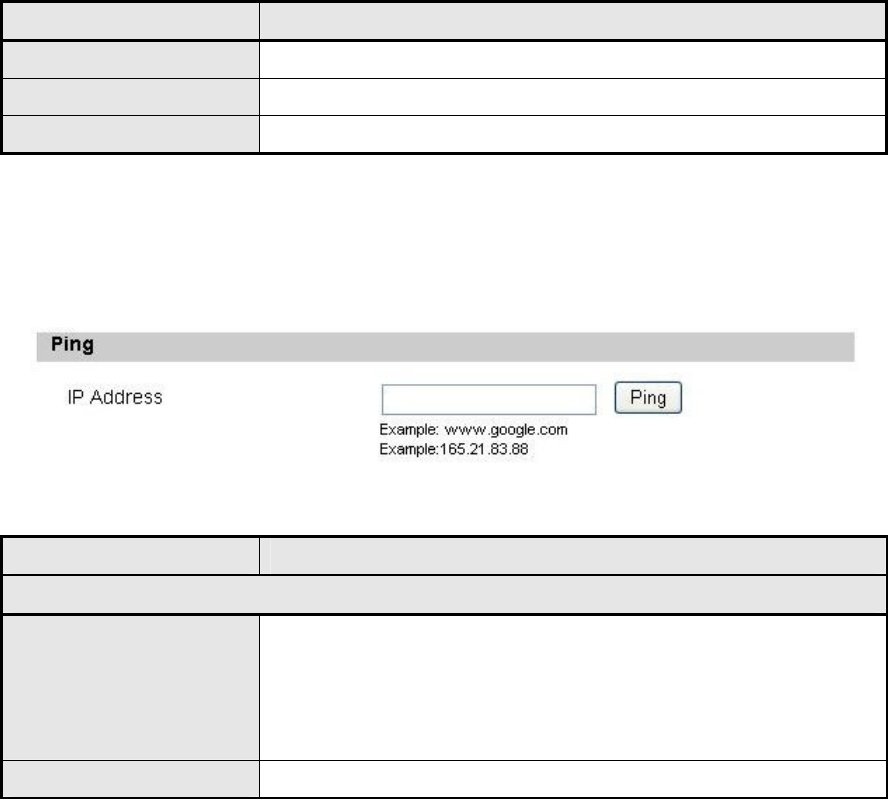
5.9. Ping
Figure 37 Networking>Ping
Name Description
Ping
IP Address The destination IP address for ping test. It can be in one
of the following formats:
IP address (ex. 165.21.83.88)
Domain name (ex. www.google.com)
Ping Commit the ping test request
Table 25 Field definition for Networking>Ping
OX-350I User Manual Rev1.2
Page 58 of 91
6. Management
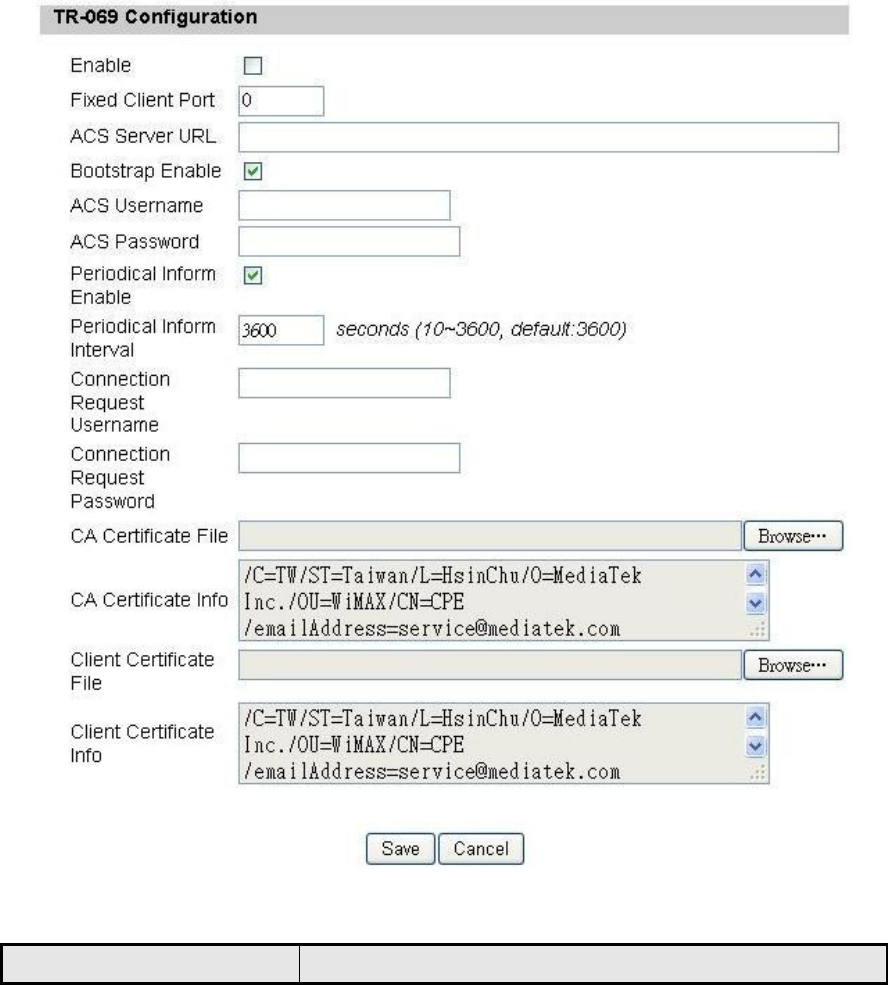
6.1. TR-069
Using TR-069 the terminals can communicate with the Auto Configuration Servers
(ACS) and establish the configuration automatically. It’s the current standard for
activation of terminals in the DSL broadband market.
Figure 38 Management>TR-069
Name Description

OX-350I User Manual Rev1.2
Page 59 of 91
Name Description
TR-069 Configuration
Enable To enable or disable the TR-069 activity on the CPE.
Fixed Client Port To specify fixed client port
ACS Server URL The ACS URL for CPE to connect to.
Bootstrap Enable Check the box to enable bootstrap.
ACS Username The username for the CPE when connected to ACS.
ACS Password The password for the CPE when connected to ACS.
Periodical Inform Enable To enable or disable the periodical inform to ACS for
CPE.
Periodical Inform Interval The interval between two periodical inform.
Connection Request
Username
Enter the username for the ACS to perform
connection request to CPE.
Connection Request
Password
Enter the password for the ACS to perform
connection request to CPE.
CA Certificate File
The CA certificate file is used to identify the certificate
of ACS when D-230 communicated ACS with HTTPS
URL.
CA Certificate Info Displays the subject field of the CA Certificate.
Client Certificate File The CLIENT certificate file is used when CPE
communicates with HTTPS URL.
Client Certificate Info Displays the subject field of the CLIENT Certificate.
Save Commit the changes made and save to CPE.
Cancel Reset fields to the last saved values.
Table 26 Field definition for Management>TR-069
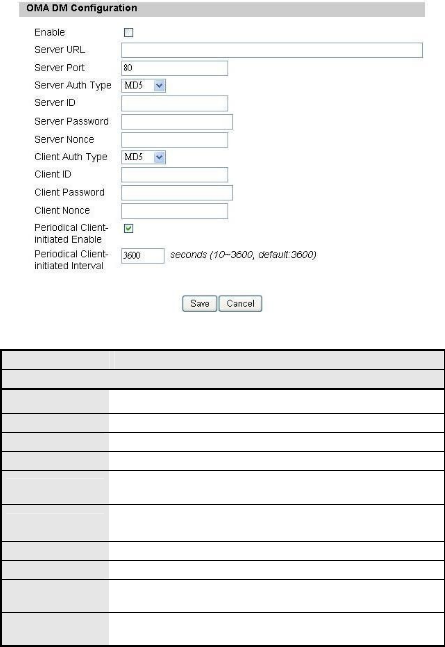
6.2. OMA-DM
Using OMA DM the terminals can communicate with the OMA DM Server and
establish the configuration automatically. It’s the current standard for activation of
terminals in OMA (Open Mobile Alliance).
OX-350I User Manual Rev1.2
Page 60 of 91
Figure 39 Management>OMA-DM
Name Description
OMA DM Configuration
Enable To enable or disable the OMA-DM activity of CPE.
Server URL The DM Server URL for CPE to connect to.
Server Port The DM Server Port for CPE to connect to.
Server Auth Type The DM Server authentication type.
Server ID The Server ID for CPE when connected to DM Server.
Server Password The Server password for CPE when connected to DM
Server.
Server Nonce Server nonce used in authentication credential calculation.
Client Auth Type The DM Client authentication type.
Client ID The Client ID for CPE when connected to DM Server.
Client Password The Client password for CPE when connected to DM Server.
OX-350I User Manual Rev1.2
Page 61 of 91
Name Description
Client Nonce Client nonce used in authentication credential calculation.
Periodical Client-
initiated Enable
To enable or disable the periodical client-initiated session to
DM server for CPE.
Periodical Client-
initiated Interval The interval between two periodical client-initiated sessions.
Save Commit the changes made and save to CPE.
Cancel Reset fields to the last saved values.
Table 27 Field definition for Management>OMA-DM
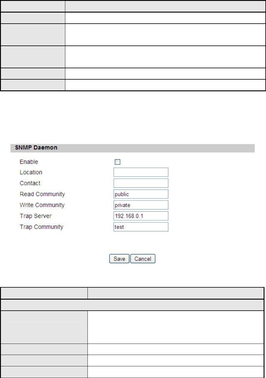
6.3. SNMP
Figure 40 Management>SNMP
Name Description
SNMP Daemon
Enable
Checking the enable button will allow SNMP
applications to query and set some of the SNMP
variables.
Location Enter the Location SNMP string variable.
Contact Enter the Contact SNMP string variable.
Read Community Enter Read community string to query SNMP data.
OX-350I User Manual Rev1.2
Page 62 of 91
Name Description
Write Community Enter Write community string to query SNMP
variables.
Trap Server Enter the IP Address of trap server where user wants
trap notifications to be sent to.
Trap community
Enter the Trap community to act as a password for
sending trap notifications to the target SNMP
manager.
Save Commit the changes made and save to CPE.
Cancel Reset fields to the last saved values.
Table 28 Field definition for Management>SNMP
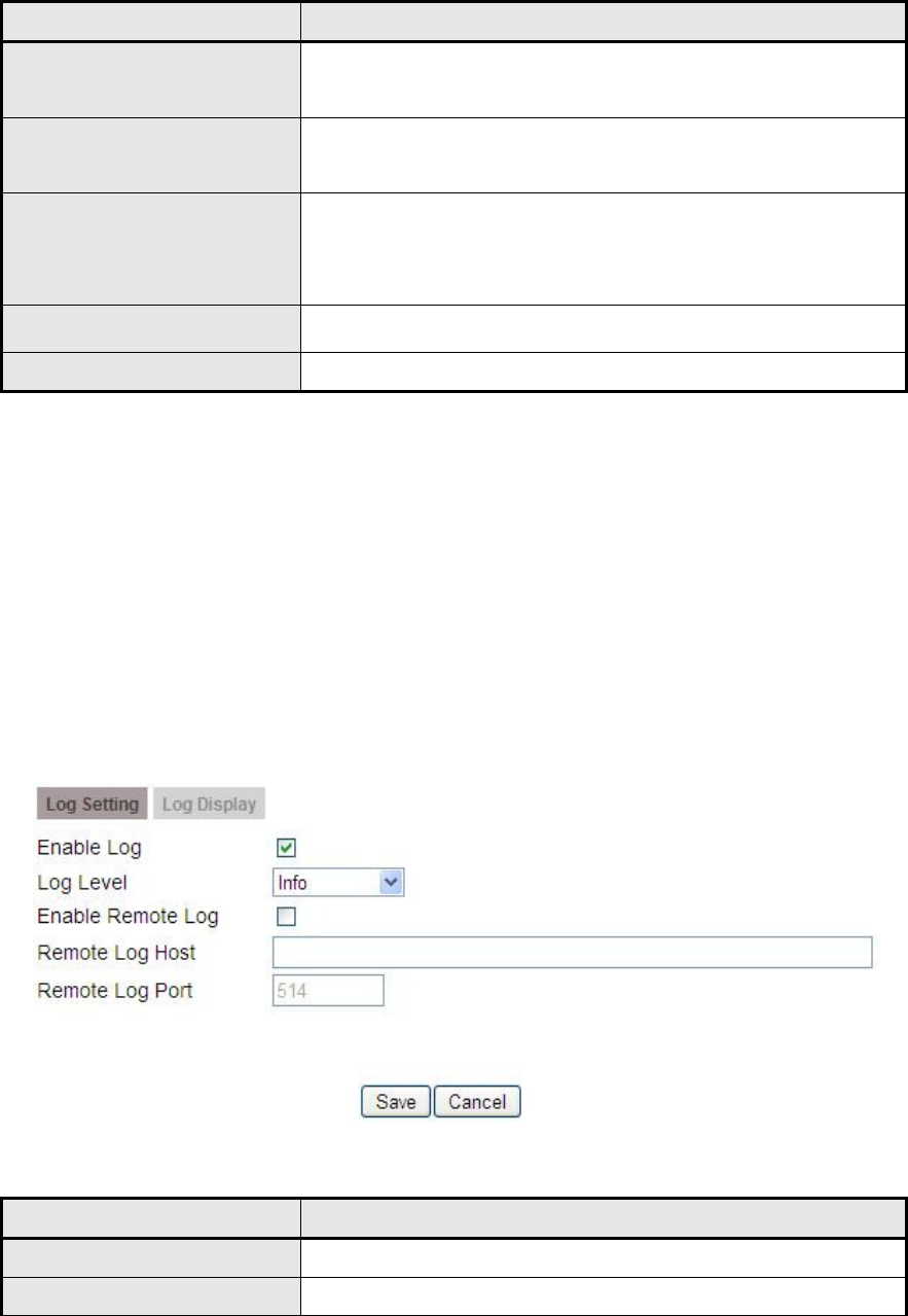
6.4. Log
6.4.1. Log Setting
The “Management>Log>Log Setting” allows user to set the remote log configure.
The “Refresh” button will clear the log window and display the most current
system log information.
Figure 41 Management>Log>Log Setting
Name Description
Enable Log Check the box to enable the log feature.
Log Level Select the log level.
OX-350I User Manual Rev1.2
Page 63 of 91
Name Description
Enable Remote Log Enable / Disable transfer log to remote syslog server.
Remote Log Host Location of the remote syslog server.
Remote Log Port What port to use for remote logging.
Save Commit the changes made and save to CPE.
Cancel Reset fields to the last saved values.
Table 29 Field definition for Management>Log>Log Setting
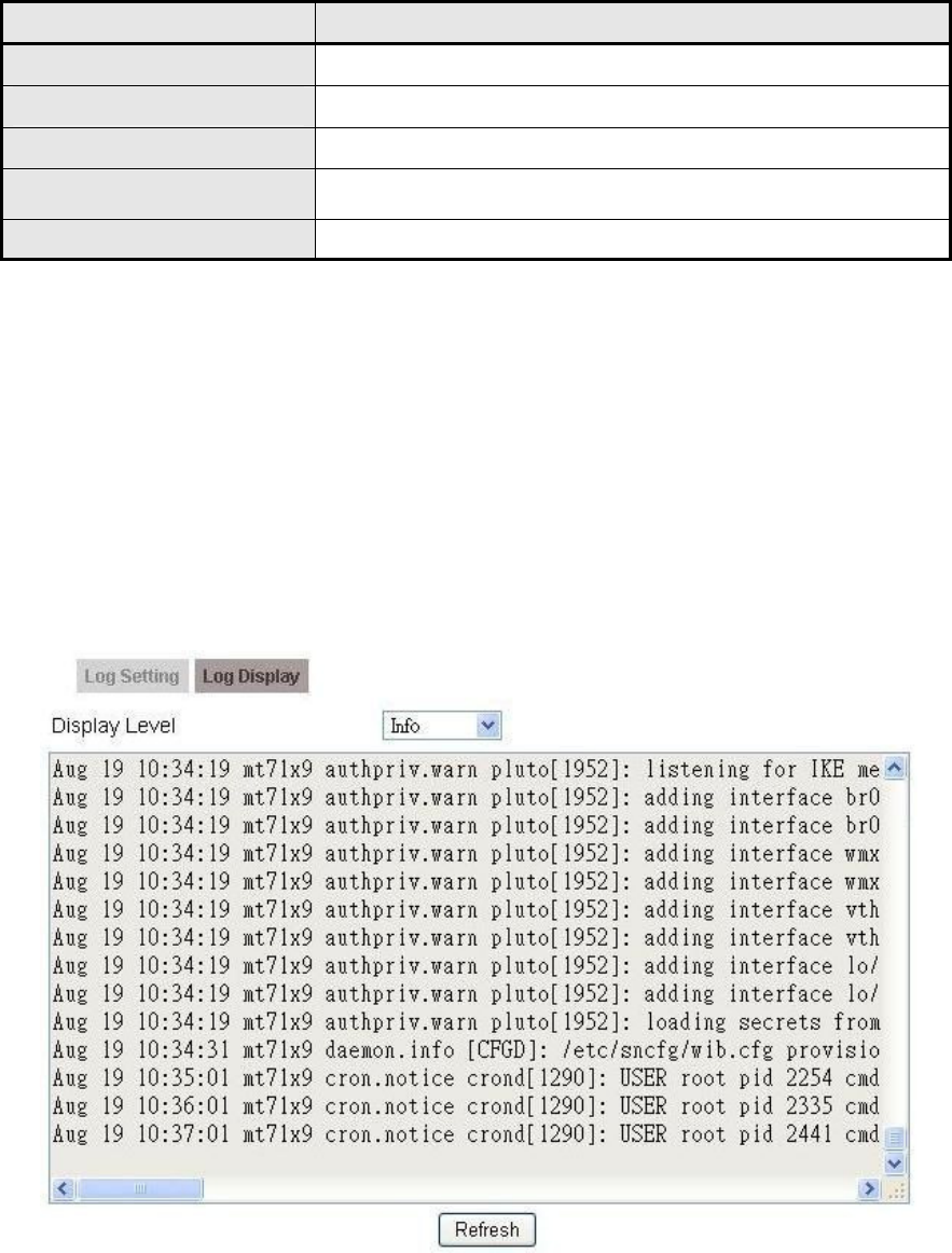
6.4.2. Log Display
The “Management>Log>Log Display” will display system log output. The
“Refresh” button will clear the log window and display the most current system log
information.
Figure 42 Management>Log>Log Display
OX-350I User Manual Rev1.2
Page 64 of 91
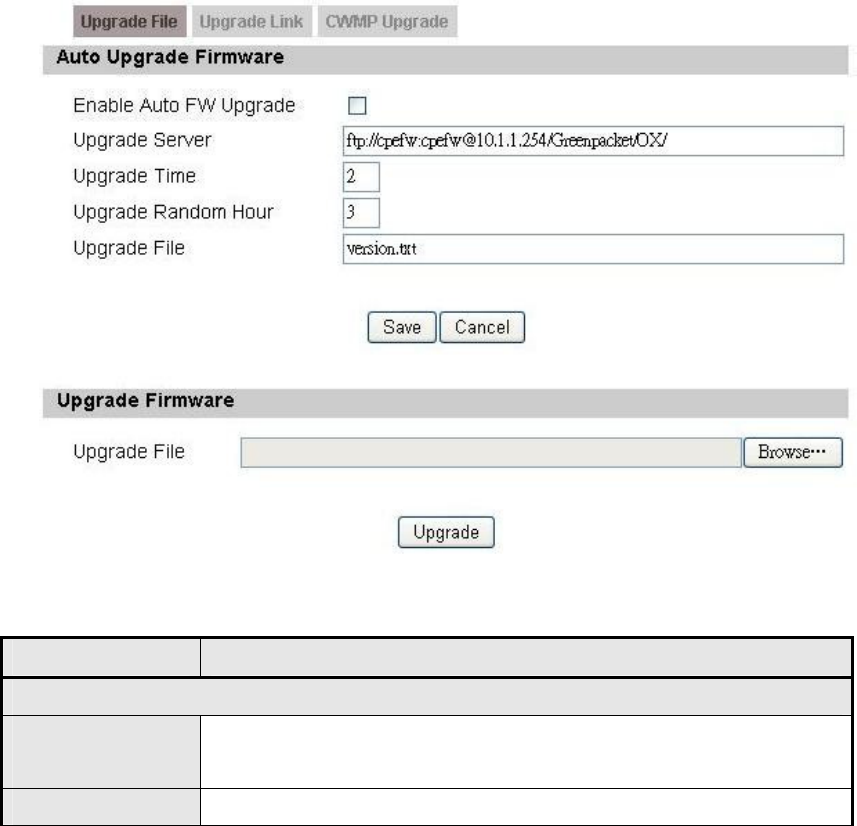
6.5. Upgrade
The “Upgrade” window allows user to upgrade the firmware on the device. Users
can choose to upgrade the firmware by entering the file path.
Note: After pressing the “Upgrade” button. It will automatically reboot the CPE and
upgrade the firmware with the specified file. User will be prompted to login
to CPE after the upgrade is complete.
6.5.1. Upgrade File
Figure 43 Management>Upgrade>Upgrade File
Name Description
Auto Upgrade Firmware
Enable Auto FW
Upgrade To enable or disable the Auto Upgrade Firmware of CPE.
Upgrade Server
Auto Firmware Update checking URL.
OX-350I User Manual Rev1.2
Page 65 of 91
Name Description
Upgrade Hour The service stating time.
Upgrade
Random Time
The random period of sleep time before actually connection
to server for checking and updating.
Upgrade File
The "Version File" in the URL.
"Version File" format :
1st line : "firmware package version"
2nd line : "firmware package tar-ball" (in the same URL
path)
Save Commit the changes made and save to CPE.
Cancel Reset fields to the last saved values.
Upgrade Firmware
Browse Enter the full path of the file user wants to upgrade. The
“browse” button will help user to find the file on the server.
Upgrade It will start upgrading the file
Status The status bar will display which segment it's processing
and what percentage of the upgrade has been completed.
Table 30 Field definition for Management>Upgrade>Upgrade File
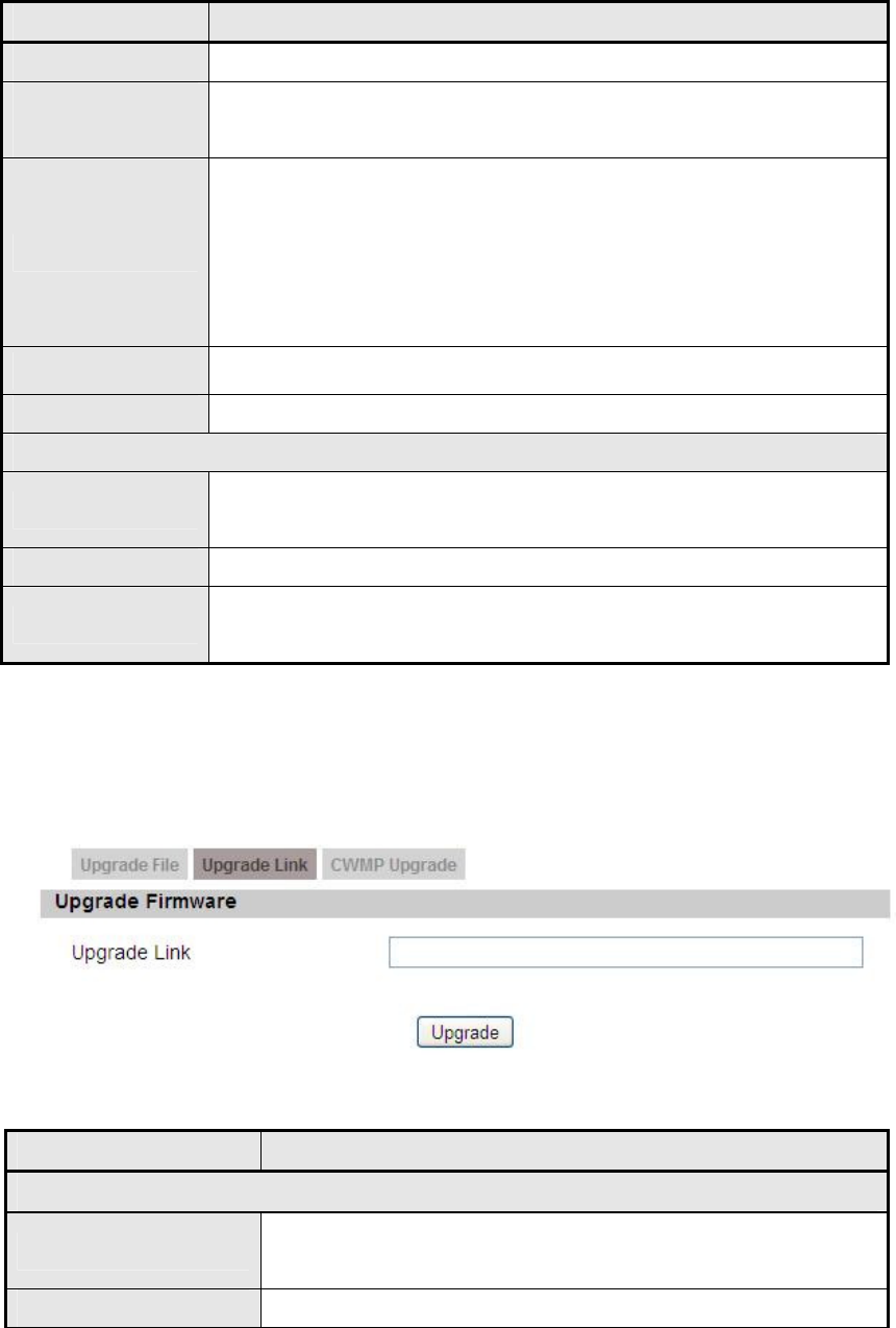
6.5.2. Upgrade Link
Figure 44 Management>Upgrade>Upgrade Link
Name Description
Upgrade Firmware
Upgrade Link Enter the complete URL path of the file that user wants
to upgrade
Upgrade It will start upgrading the file
OX-350I User Manual Rev1.2
Page 66 of 91
Name Description
Status
The status bar will display which segment it's
processing and what percentage of the upgrade has
been completed.
Table 31 Field definition for Management>Upgrade>Upgrade Link
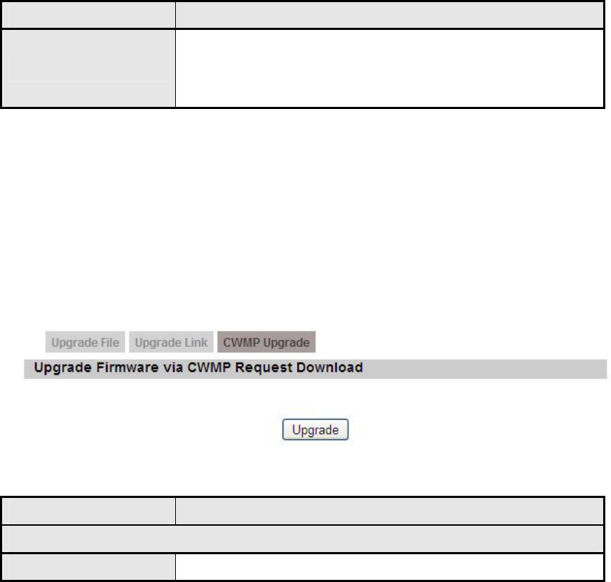
6.5.3. CWMP Upgrade
TR-069 technical specification entitled CPE WAN Management Protocol (CWMP).
It defines an application layer protocol for remote management of end-user
devices.
Figure 45 Management>Upgrade>CWMP Upgrade
Name Description
Upgrade Firmware via CWMP Request Download
Upgrade It will start upgrading
Table 32 Field definition for Management>Upgrade>CWMP Upgrade
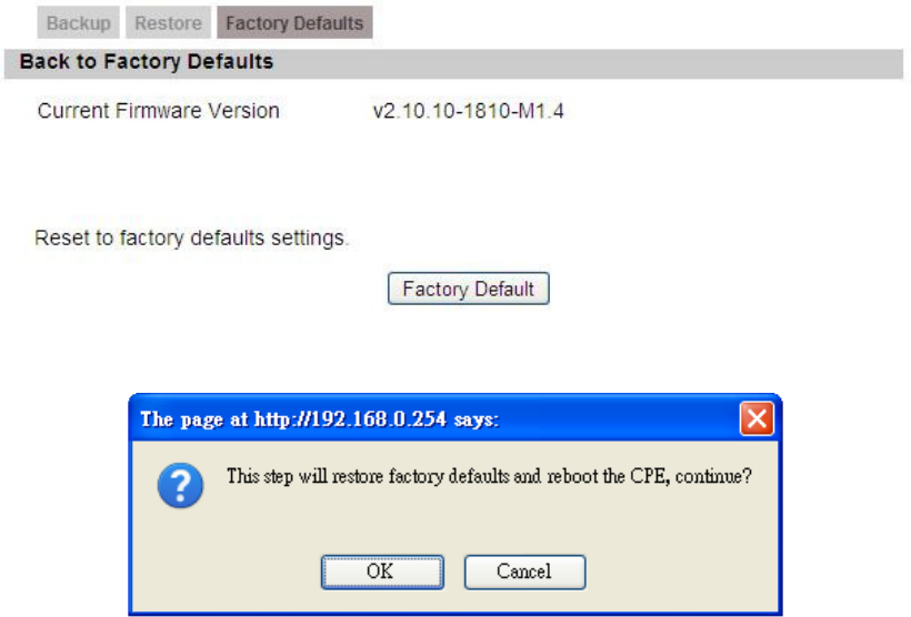
6.6. Recovery
Recovery will set all the configurations back to factory defaults. Any configurations
that user has made will be changed back to the factory default settings. After
selecting “Factory Default” button, user will be prompted with a window to confirm
or cancel the action.
Warning: Restore factory defaults will clear any IP addresses and setting that may
have been configured on the CPE.
OX-350I User Manual Rev1.2
Page 67 of 91
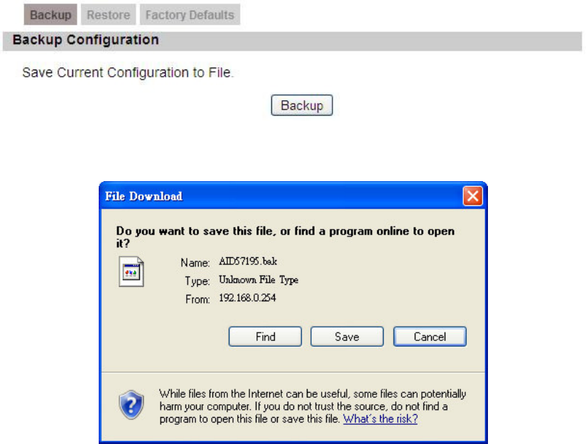
6.6.1. Backup
Figure 46 Management>Recovery>Backup
Figure 47 File Download
OX-350I User Manual Rev1.2
Page 68 of 91
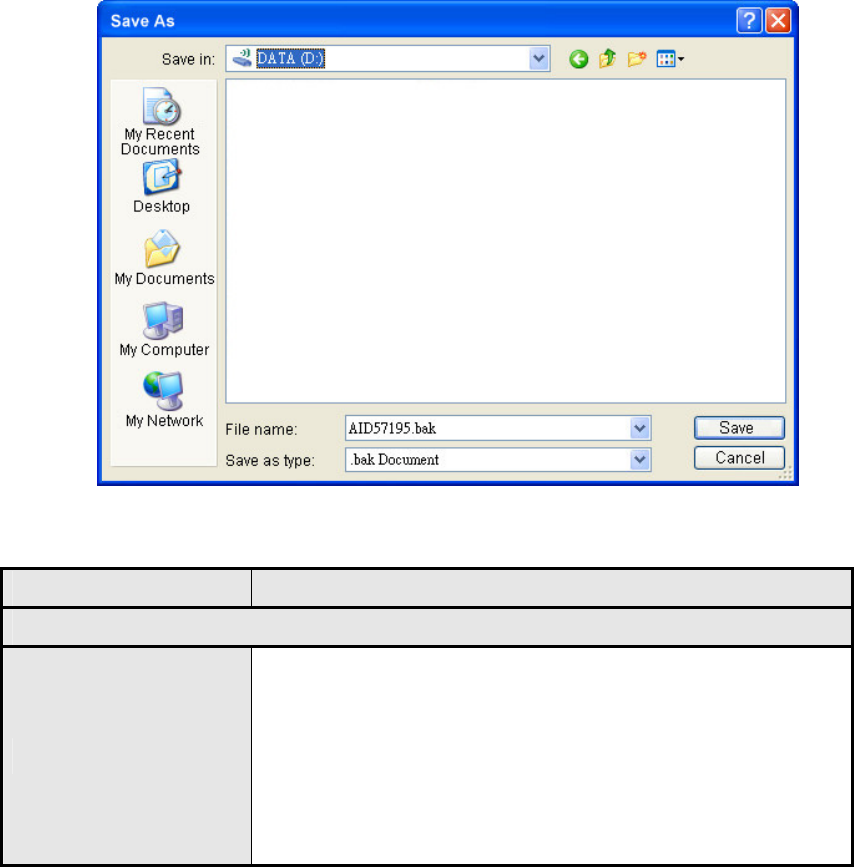
Figure 48 Save File As
Name Description
Backup Configuration
Backup
Click the "Backup" button o save the current
configuration on the CPE. After user clicks the
"Backup" button "File Download" window will pop-up
and prompt user to save the file. In the "Save As"
window, enter the name and location, where user
wishes to download the file to.
Table 33 Field definition for Management>Recovery>Backup
OX-350I User Manual Rev1.2
Page 69 of 91
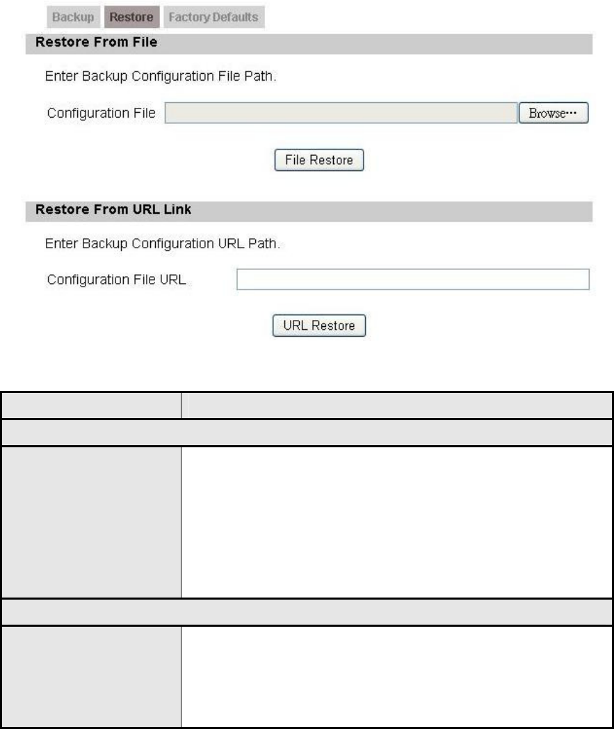
6.6.2. Restore
Figure 49 Management>Recovery>Restore
Name Description
Restore From File
File Restore
Enter the path of the configuration file user wants to
restore. Click on the "Browse" button to help user to
navigate through directories and search for the file. After
user enters the complete file path, click the "File
Restore" button. It will begin restoring the configuration
from the file specified.
Restore From URL Link
URL Restore
Enter the configuration URL path user wants to restore
from. After entering the complete URL path, click the
"URL Restore" button. It will begin restoring the
configuration from the URL location user specified.
Table 34 Field definition for Management>Recovery>Restore
OX-350I User Manual Rev1.2
Page 70 of 91
6.6.3. Factory Defaults
Figure 50 Management>Recovery>Factory Defaults
Figure 51 Restore to factory reset warning
OX-350I User Manual Rev1.2
Page 71 of 91
7. VPN
VPN (Virtual Private Network) is a network that is implemented in an additional
software layer on top of an existing larger network for the purpose of providing a
secure extension of a private network into an insecure network such as the
Internet. The links between nodes of a VPN are formed over logical connections
or virtual circuits between hosts of the larger network.
VPNs are often installed by organizations to provide remote access to a secure
organizational network. Generally, a VPN has a network topology more complex
than a point-to-point connection. VPNs are also used to mask the IP address of
individual computers within the Internet in order, for instance, to surf the World
Wide Web anonymously or to access location restricted services, such as Internet
television. Here, VPN Settings allow user to set rules for VPN, and it supports
PPTP, L2TP, and IPsec.
7.1. PPTP
The Point-to-Point Tunneling Protocol (PPTP) is a method for implementing virtual
private networks. PPTP does not provide confidentiality or encryption; it relies on
the protocol being tunneled to provide privacy.
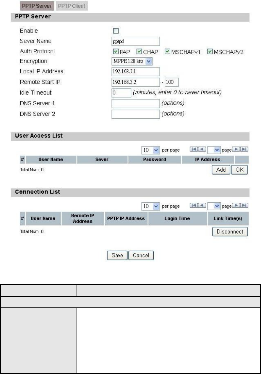
7.1.1. PPTP Server
A PPTP Server (Point-To-Point Tunneling Protocol) allows user to connect
securely from a place (such as the house) to a LAN located in another location,
such as the office. This way user can use the services provided in the office at the
comfort of the house. The definition for each field of PPTP Server is shown on
Table 35.
OX-350I User Manual Rev1.2
Page 72 of 91
Figure 52 VPN>PPTP>PPTP Server
Name Description
PPTP Server
Enable Activate PPTP server.
Server Name Offer a service name
Auth Protocol
Require the peer to authenticate itself before allowing
network packets to be sent or received. We support the
following protocol:
PAP: Password Authentication Protocol

OX-350I User Manual Rev1.2
Page 73 of 91
Name Description
CHAP: Challenge Handshake Authentication
Protocol
MSCHAP: Microsoft Challenge Handshake
Authentication Protocol
MSCHAPv2: Microsoft Challenge Handshake
Authentication Protocol, Version 2
Encryption
Encryption Scheme:
No
MPPE 40 bits: 40-bit encryption with MPPE
MPPE 128 bits: 128-bit encryption with MPPE
Auto: automatically select
Local IP Address The IP of router
Remote Start IP As sessions are established, IP addresses are assigned
starting from “Remote Start IP”
Idle Timeout Disconnect if the link is idle for the assigned seconds
DNS Server 1 The primary DNS (Domain Name Server) addresses to
clients
DNS Server 2 The secondary DNS (Domain Name Server) addresses
to clients
User Access List
User name User ID to connect PPTP server via the selected Auth
Protocol
Server Server protocol type
Password Password to connect PPTP server via the selected Auth
Protocol
IP address IP address of the connected client
Connection List
User name The user name of the connection
Remote IP address The peer address of the connection
PPTP IP address The assigned IP address of PPTP
Login Time The time of the connection created
Link Time(s) Timer from the connected time
Save Commit the changes made and save to the CPE
Cancel Reset fields to the last saved values
OX-350I User Manual Rev1.2
Page 74 of 91
Table 35 Field definition for VPN>PPTP>PPTP Server
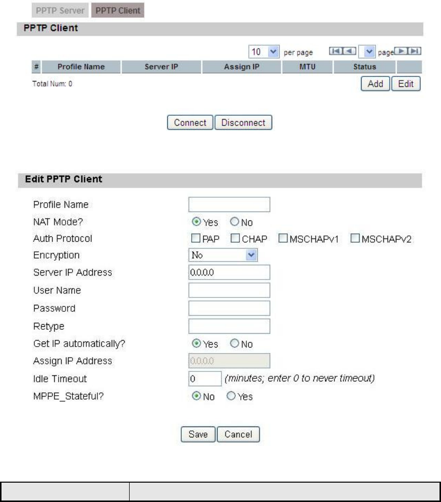
7.1.2. PPTP Client
User could setup PPTP Client as shown in Figure 53 and Figure 54. The definition
for each field of PPTP Client is shown on Table 36.
Figure 53 VPN>PPTP>PPTP Client
Figure 54 VPN>PPTP>PPTP Client>Add
Name Description

OX-350I User Manual Rev1.2
Page 75 of 91
Name Description
PPTP Client
Add Add a new connection setting
Edit Edit the existed connection setting
Edit PPTP Client
Profile Name The name for this connection setting
NAT Mode? Enable or disable NAT when connected to PPTP server.
Yes: enable
No: disable
Auth Protocol
The Authentication protocol of the peer required. Select
which Authentication protocol to use.
PAP
CHAP
MSCHAPv1
MSCHAPv2
Encryption Encryption scheme
Server IP Address The IP address of PPTP server
Username The user ID to connect PPTP server via the selected
Auth Protocol
Password The password of the corresponding user ID
Retype Type the “Password” again
Get IP automatically? Obtain the dynamic IP address, assigned by the PPTP
server
Assign IP Address Assign the static IP address for this connection setting
Idle Timeout Disconnect if the link is idle for the assigned seconds
MPPE_Stateful Allow MPPE to use stateful mode. Stateless mode is still
attempted first. The default is to disallow stateful mode.
Save Commit the changes made and save to CPE
Cancel Reset fields to the last saved values
Table 36 Field definition for VPN>PPTP>PPTP Client
7.2. L2TP
In computer networking, Layer 2 Tunneling Protocol (L2TP) is a tunneling protocol
OX-350I User Manual Rev1.2
Page 76 of 91
used to support virtual private networks (VPNs). It does not provide any
encryption or confidentiality by itself. It relies on an encryption protocol that it
passes within the tunnel to provide privacy. The entire L2TP packet, including
payload and L2TP header, is sent within a UDP datagram. It is common to carry
Point-to-Point Protocol (PPP) session within an L2TP tunnel. L2TP does not
provide confidentiality or strong authentication by itself. IPsec is often used to
secure L2TP packets by providing confidentiality, authentication and integrity.
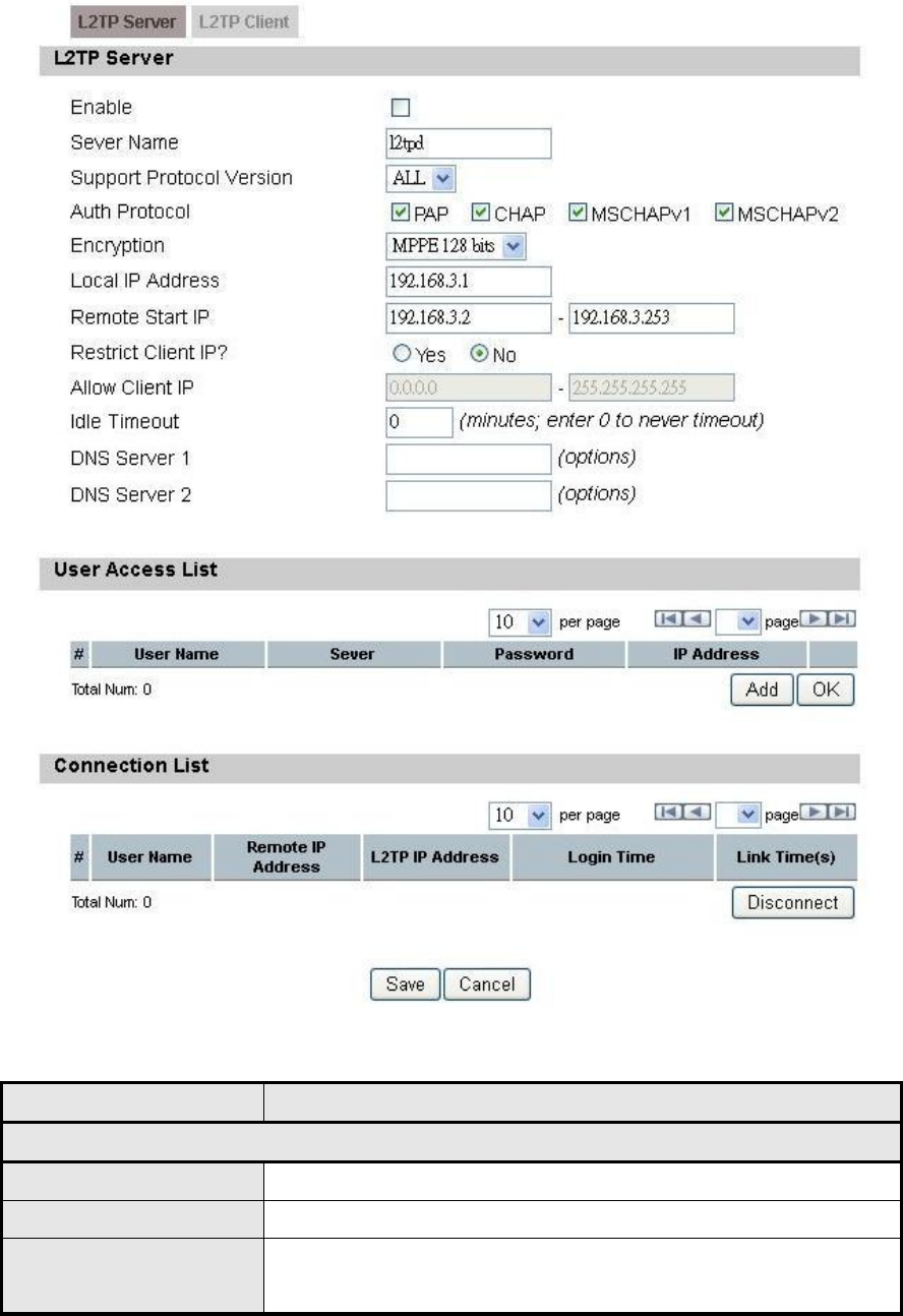
7.2.1. L2TP Server
User can setup CPE from web page as shown in Figure 55. The definition for
each field of PPTP Server is shown on Table 37.
OX-350I User Manual Rev1.2
Page 77 of 91
Figure 55 VPN>L2TP>L2TP Server
Name Description
L2TP Server
Enable Check the check box to activate L2TP server.
Server Name Enter a service name
Support Protocol
Version
The supported protocol of L2TP messages
ALL: L2TPv2 and L2TPv3

OX-350I User Manual Rev1.2
Page 78 of 91
Name Description
2: L2TPv2 only
3: L2TPv3 only
Auth Protocol
Require the peer to authenticate itself before allowing
network packets to be sent or received. The following
protocols are supported:
PAP: Password Authentication Protocol
CHAP: Challenge Handshake Authentication
protocol
MSCHAPv1: Microsoft Challenge Handshake
Authentication Protocol
MSCHAPv2: Microsoft Challenge Handshake
Authentication Protocol, Version 2
Encryption
Encryption Scheme
No
MPPE 40 bits: 40-bit encryption with MPPE
MPPE 128 bits: 128-bit encryption with MPPE
Auto: automatically select
Local IP Address The IP of router
Remote Start IP As sessions are established, IP addresses are assigned
starting from “Remote Start IP”
Restrict Client IP? To restrict client IP address range for the client
Allow Client IP The IP address range for the client
Idle Timeout Disconnect if the link is idle for the given number of
seconds
DNS Server 1 The primary DNS (Domain Name Server) addresses to
the clients
DNS Server 2 The secondary DNS (Domain Name Server) addresses
to the clients
User Access List
User Name User ID to connect L2TP server via the selected Auth
Protocol
Server Server Protocol type
Password Password to connect L2TP server via the selected Auth
Protocol
OX-350I User Manual Rev1.2
Page 79 of 91
Name Description
IP Address IP address of the connected client
Connection List
User Name The user name of the connection
Remote IP Address The peer address of the connection
L2TP IP Address The assigned IP address of L2TP
Login Time The time of the connection created
Link Time(s) Elapsed time connected
Save Commit the changes made and save to CPE
Cancel Reset fields to the last saved values
Table 37 Field definition for VPN>L2TP>L2TP Server
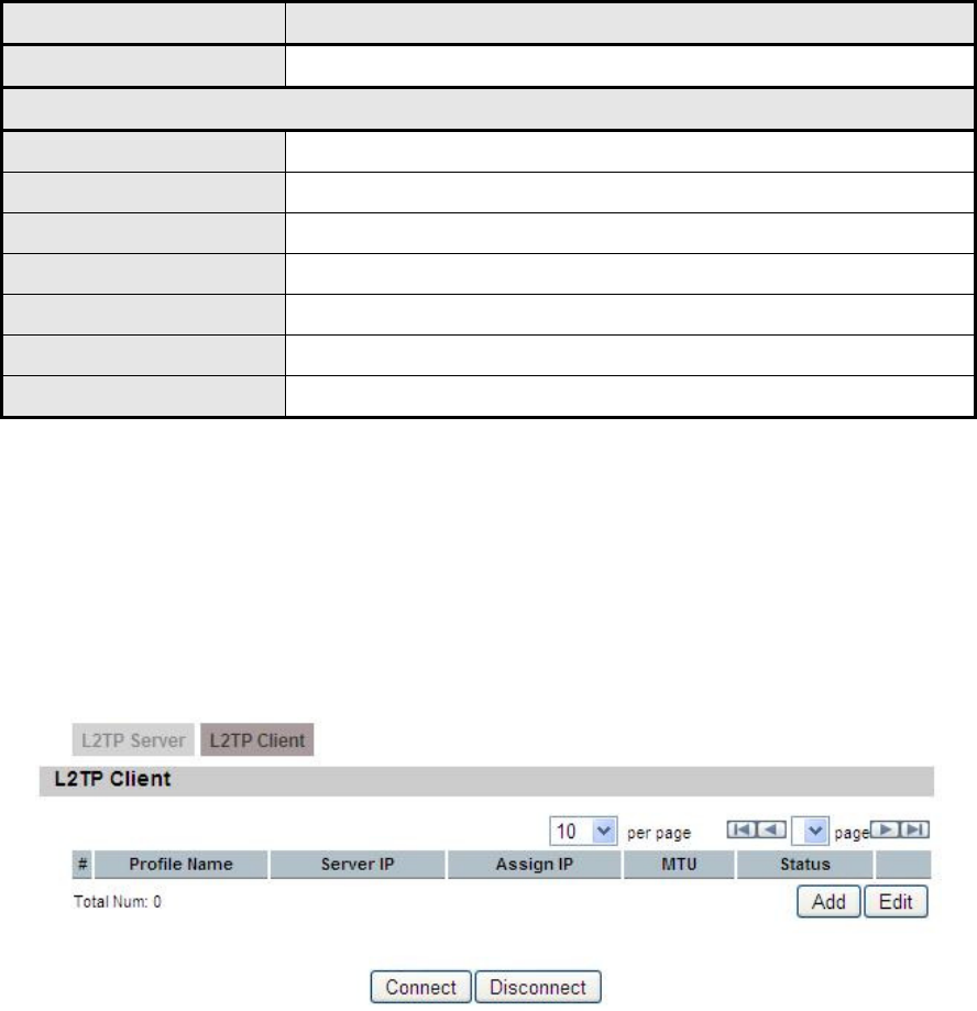
7.2.2. L2TP Client
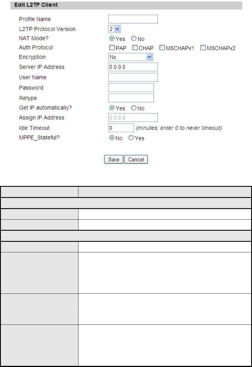
User could setup PPTP Client as shown in Figure 56 and Figure 57. The definition
for each field of PPTP Client is shown on Table 38.
Figure 56 VPN>L2TP>L2TP Client
OX-350I User Manual Rev1.2
Page 80 of 91
Figure 57 VPN>L2TP>L2TP Client>Add
Name Description
L2TP Client
Add Add a new connection setting
Edit Edit the existed connection setting
Edit L2TP Client
Profile Name The name of this connection setting
L2TP Protocol Version
The message of L2TP protocol version for this
connection setting
2: L2TPv2 only
3: L2TPv3 only
NAT Mode?
Enable or disable NAT when connected to PPTP server
Yes: enable
No: disable
Auth Protocol
The Authentication Protocol of the peer required. Select
which Authentication protocol to use.
PAP
CHAP

OX-350I User Manual Rev1.2
Page 81 of 91
Name Description
MSCHAPv1
MSCHAPv2
Encryption Encryption Scheme
Server IP Address The IP address of L2TP server
Username The username to connect L2TP server via the selected
Auth Protocol
Password The password of the corresponding username
Retype Type the “Password” again
Get IP Automatically? Obtain the dynamic IP address, assigned by the L2TP
server
Assign IP Address Assign the static IP address for this connection setting
Idle Timeout Disconnect if the link is idle for the assigned seconds
MPPE_Stateful Allow MPPE to use stateful mode. Stateless mode is
still attempted first. The default is to disallow stateful
mode.
Save Commit the changes made and save to CPE
Cancel Reset fields to the last saved values
Table 38 Field definition for VPN>L2TP>L2TP Client
7.3. IPsec
Internet Protocol Security (IPsec) is an end-to-end security solution and operated
at the IP Layer. It provides secure communication between pairs of hosts, pairs of
security gateways or between security gateways and a host. It’s based on a suite
of protocols for securing IP traffic by authenticating and encrypting each IP packet
of the data stream.
Figure 58 VPN>IPsec Overview
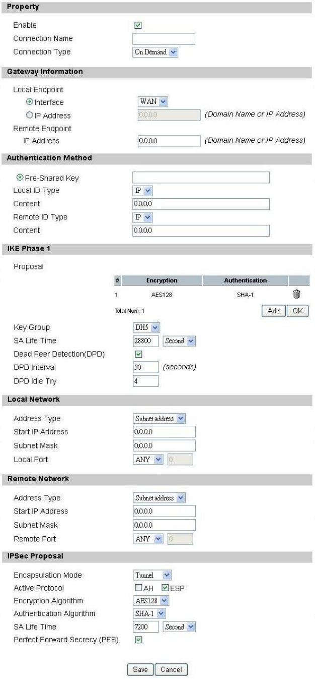
OX-350I User Manual Rev1.2
Page 82 of 91

OX-350I User Manual Rev1.2
Page 83 of 91
Figure 59 VPN>IPsec>Add
Name Description
Add Click the "Add" button to add an IPsec connection rule
Property
Enable Enable IPsec connection.
Connection Name The name of the connection
Connection Type
Select the connection type
Initiator
On Demand
Responder
Gateway Information
Local Endpoint
Interface The interface of the CPE public-network interface
Local Endpoint IP
Address
The IP address or Domain Name of the CPE
public-network interface
Remote Endpoint IP
Address The IP address or Domain Name of the remote peer.
Authentication Method
Pre-Shared Key The pre-share key that two security gateways use to
authenticate
Local ID Type
States how the CPE should be identified for
authentication
IP: The CPE is identified by the assigned IP for
authentication. The default value is 0.0.0.0.
Content The IP address
Remote ID Type
States how the remote peer should be identified for
authentication
IP: The remote peer is identified by the assigned IP for
authentication. The default value is 0.0.0.0, and this
means CPE will accept any IP.
Content The IP address
IKE Phase 1

OX-350I User Manual Rev1.2
Page 84 of 91
Name Description
Proposal Add
Press the Add button to enter an Encryption and
Authentication algorithm. Click the trash to remove the
selected algorithm. Encryption Algorithm:
DES
3DES
AES128
AES192
AES256
Authentication Algorithm:
MD5
SHA-1
Proposal OK Click the OK button to exit the table edit mode
Key Group The DH group used to negotiate the IKE/ISAKMP SA.
SA Life Time
The period that the keying channel of a connection
(IKE/ISAKMP SA) should last before being
renegotiated.
Dead Peer Detection
(DPD)
Enable or disable the Dead Peer Detection protocol
(RFC 3706)
DPD Interval The time interval when R_U_THERE messages are
sent to the peer.
DPD Idle Try
The retry counter for DPD. The timeout interval is "DPD
interval" multiplied by "DPD Idle Try". After the timeout
interval all connections to the peer are deleted if they
are inactive.
Local Network The private subnet behind the CPE.
Address Type
Single Address: The private subnet consisting of one IP
address.
Subnet address: The private subnet consisting within
the subnet IP addresses.
Start IP Address The only IP address allowed in the subnet
Subnet Mask The netmask of the subnet (Subnet address)
Local Port Restrict the traffic selector to a single protocol and/or
port.

OX-350I User Manual Rev1.2
Page 85 of 91
Name Description
Any: No restriction
ICMP: Restrict the traffic selector to ICMP protocol.
TCP: Restrict the traffic selector to TCP protocol. If
the port number is 0, all TCP port numbers are
accepted.
UDP: Restrict the traffic selector to UDP protocol. If
the port number is 0, all UDP port numbers are
accepted.
Remote Network The private subnet behind the remote peer.
Address Type
Single Address: The private subnet consisting of one IP
address.
Subnet address: The private subnet consisting of
subnet IP addresses.
Start IP Address The only IP address allowed in the subnet
Subnet Mask The netmask of the subnet (Subnet address)
Remote Port
Restrict the traffic selector to a single protocol and/or
port.
Any: No restriction
ICMP: Restrict the traffic selector to ICMP protocol.
TCP: Restrict the traffic selector to TCP protocol. If
the port number is 0, all TCP port numbers are
accepted.
UDP: Restrict the traffic selector to UDP protocol. If
the port number is 0, all UDP port numbers are
accepted.
IPSec Proposal
Encapsulation Mode
The type of the connection:
Tunnel: signifying a host-to-host, host-to-subnet, or
subnet-to subnet tunnel.
Transport: signifying host-to-host transport made.
Active Protocol Whether authentication should be done as part of ESP
encryption and/or separately using the AH protocol.
Encryption Algorithm
NULL
AES128

OX-350I User Manual Rev1.2
Page 86 of 91
Name Description
AES192
AES256
DES
3DES
Authentication
Algorithm
MD5
SHA-1
SA Life Time
The time interval a particular instance of a connection (a
set of encryption/authentication key for user packets)
should last, from successful negotiation to expiry.
Perfect Forward
Secrecy (PFS)
Whether Perfect Forward Secrecy of keys is desired on
the connection's keying channel.
Save Commit the changes made and save to the CPE device
Cancel Reset fields to the last saved values.
Table 39 Field definition for VPN>IPsec>Add

OX-350I User Manual Rev1.2
Page 87 of 91
8. Installation and Grounding
Device
Before installing the Outdoor CPE Device
Before installing, it is important to comply with the precautions listed below.
It must be installed by qualified service personnel who are well-trained in the
correct procedures for handling and installing the equipment.
Avoid installing or working on equipment in adverse weather conditions.
Once it must be installed in adverse weather conditions, it’s necessary to
well protect the equipment.
Do not install the device near overhead power lines or power circuits, or
where the device can fall onto such power lines or circuits.
Do not disassemble the product. Opening or removing covers may expose
you to electric shock. Warranty void if seal is broken.
Do not place or construct objects in close proximity to the device.
Be sure to check the supplied mounting accessory is correct as listed in
Figure 60. Please be noted that the mounting kits should be used for the
pole with diameter between 34 ~ 49 mm.
Under normal operating condition, it should be at least 60 cm away from the
body of the user.
Mounting Accessories:
Bracket with Tab: 1 pc
Bracket W/L Tab: 1 pc
Arm Bracket: 1 pc
Screws with length 60mm: 2 pcs
Screws with length 35mm: 2 pcs
Nuts: 3 pcs
Split Washers: 3 pcs
Flat Washers: 3 pcs
Lockwasher: 2 pcs
Figure 60 Mounting accessory list
OX-350I User Manual Rev1.2
Page 88 of 91
An Overview of the Outdoor CPE Device Installation
Service personnel needs to follow the steps for installing Outdoor CPE Device
1. Pole-mounting or Wall-mounting the Outdoor CPE Device.
2. Grounding the Outdoor CPE Device
3. Connect the Outdoor CPE Device to PoE unit
4. Connect PC to PoE unit for configuring the Outdoor CPE Device
5. Connect the PoE unit to the power source to power up the Outdoor CPE
Device
6. Use PC to configure the Outdoor CPE Device
Pole-Mounting the Outdoor CPE Device
In the following steps, it introduces how to pole-mounting the Outdoor CPE
Device.
1. Assemble the mounting hardware brackets onto pole first: Take the Screws
with 60mm length to pass through the Split washer and Flat washer in order,
and then screw the Brackets together with nuts.
2. Use the Screw with 35mm length to attach the Outdoor CPE Device to the tab
of the Bracket. Ensure the Lockwasher is located between the Bracket’s tab
and the Outdoor CPE Device’s tab. Be sure to orient the Outdoor CPE
Device with the connector towards the bottom. Remember to orderly add the
Split washer, Flat washer and Nuts as shown in Figure 61. Do not
over-tighten before finishing the Outdoor CPE Device alignment.
3. Adjust the azimuth and elevation of the Outdoor CPE Device toward the
direction of WiMAX Base Station location.
4. Tighten the screws to secure the Outdoor CPE Device tightly.
It is not necessary to use Arm Bracket for pole-mounting. Arm Bracket is only
used for wall-mounting.
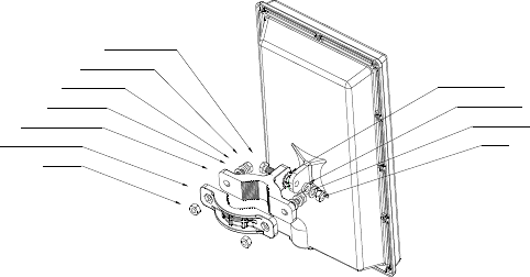
OX-350I User Manual Rev1.2
Page 89 of 91
Nut
Bracket W/L Tab
Bracket with Tab
Flat washer
Split washer
Screw (60mm)
Screw (35mm)
Nut
Flat washer
Split washer
Lockwasher
Figure 61 Pole-Mount the Outdoor CPE Device
Wall-Mounting the Outdoor CPE Device
In the following steps, it introduces how to wall-mounting the Outdoor CPE
Device.
1. Install the Bracket with tab on a wall by using two mounting screws
appropriate for the wall’s construction material. The appropriate mounting
hardware should be purchased directly from a local supplier.
2. Connect the Arm Bracket to Outdoor CPE Device with the 35mm length
Screw, Lockwasher, Split washer, Flat washer, and Nut orderly as shown in
Figure 62. Ensure the Lockwasher is located between the Bracket’s tab and
the Outdoor CPE Device’s tab. Do not over-tighten before finishing the
Outdoor CPE Device alignment.
3. Secure the other side of Arm Bracket along with Lockwasher to the Bracket’s
tab mounted on wall. Ensure that the bolt head is positioned in the socket of
the Bracket. Do not over-tighten before finishing the Outdoor CPE Device
alignment.
4. Adjust the azimuth and elevation of the Outdoor CPE Device toward the
direction of WiMAX Base Station location.
5. Tighten the screws to secure the Outdoor CPE Device tightly.
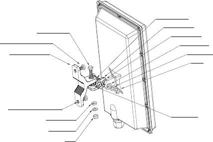
OX-350I User Manual Rev1.2
Page 90 of 91
Nut
Flat washer
Split washer
Lockwasher
Arm Bracket
Customer supplied screw
Nut
Flat washer
Split washer
Screw (35mm)
Bracket with Tab
Screw (35mm)
Customer supplied screw
Lockwasher
Figure 62 Wall-Mount the Outdoor CPE Device
Grounding the Outdoor CPE Device
Grounding the Outdoor CPE Device is essential to avoid serious injury to service
personnel and damage to the Outdoor CPE Device. Please be noted that
minimum #16 AWG wire with the color combination green-and-yellow should be
used for the grounding. The following steps introduce how to ground the Outdoor
CPE Device.
1. Remove the ground screw installed on the side of the Outdoor CPE Device,
as shown in
2. Cut the required length of the grounFigure 63.d wire, and then strip the
insulation from the ground wire by using either a wire cutter/stripper or utility
knife.
3. Crimp the ground wire to the copper cable lug, and then connect the cable
lug to the grounding connection on the side of the Outdoor CPE Device.
Please be noted that the thickness of the cable lug should be less than
0.85mm.
4. Tighten the screw by using the appropriate size and type of screw driver to
secure the copper cable lug to the Outdoor CPE Device.
5. Strip the other end of the ground wire and connect to the main ground
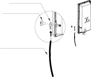
OX-350I User Manual Rev1.2
Page 91 of 91
Copper Cable Lug
Ground Wire to Earth
Grounding Screw
Figure 63 Connect the ground wire