Greenheck Fan Heat Recovery Unit With Evaporative Cooling 45 Users Manual
HEAT RECOVERY UNIT WITH EVAPORATIVE COOLING HRE-20 461248HRE_iom
HRE-90 461248HRE_iom_1
90 to the manual 776ffa43-544e-4e6a-976f-9ca3ac8b3c34
2015-02-09
: Greenheck-Fan Greenheck-Fan-Heat-Recovery-Unit-With-Evaporative-Cooling-45-Users-Manual-562474 greenheck-fan-heat-recovery-unit-with-evaporative-cooling-45-users-manual-562474 greenheck-fan pdf
Open the PDF directly: View PDF ![]() .
.
Page Count: 44
RECEIVING AND HANDLING
The HRE is thoroughly inspected and test run at the factory. However, damage may occur during
shipping and handling. Upon delivery, inspect the unit for both obvious and hidden damage.
If damage is found, record all necessary information on the bill of lading and file a claim with
the final carrier. In addition, ensure all accessory items are present. Some accessory items are
stored inside the unit during shipping.
SAFETY WARNING
Improper installation, adjustment, alteration, service or maintenance can cause property
damage, injury or death. Read this installation, operation, and maintenance manual thoroughly
before installing or servicing this equipment. Installation and service must be performed by a
qualified installer, service agency, or the gas supplier.
PART #461248
READ AND SAVE THESE INSTRUCTIONS
®
HEAT RECOVERY UNIT
WITH EVAPORATIVE COOLING
Models: HRE-20, 45, 55, & 90
INSTALLATION, OPERATION AND MAINTENANCE
MANUAL
Indirect Evaporative Cooler
(Exhaust/Scavenger Airstream)
Direct Evaporative Cooler
(Outdoor/Supply Airstream)
INSTALLATION SUPPLEMENT
Refer to the following
installation supplement for
HRE units when supplied with
Indirect Gas (IG) heating:
Model PVF, Indirect Gas
Fired Furnaces for Energy
Recovery Units, Part #461006
SAVE THIS MANUAL
This manual is the property
of the owner, and is required
for future maintenance. This
manual should remain with
each HRE unit when the job
is complete.
2
TABLE OF CONTENTS
Storage and Basic Operation ..............2
Installation ..............................3
Lifting .................................3
Unit Weights & Recommended Roof
Openings ............................3
Roof Curb Mounting .....................4
Rail Mounting ...........................5
Ductwork Connections ...................5
Electrical Information...................6-7
Service Clearances ......................8
Dimensional Data/Access Door Description ..9
Evaporative Cooling Modules
Evap Module Installation and Start-Up ..10-11
Water Supply Connection Location ........11
Water Control Options................12-13
Drain & Overflow Connection Locations ....14
Troubleshooting........................15
Maintenance...........................16
Optional Accessories .................17-28
Electric Heater Application/Operation ......17
Frost Control Application/Operation........18
Economizer Application/Operation.........19
Variable Frequency Drives ............20-21
Typical Wiring Diagram ..................22
Sensors and Lights ..................23-24
Remote Control Panel & Wiring ........25-27
Sensors Mounted by Factory .............28
Start-Up Checklist
Unit ...............................29-30
Evaporative Cooler .....................30
Optional Accessories....................31
Fan ...............................32-33
Energy Recovery Wheel .................34
Routine Maintenance Checklist...........35
Belts and Motors .......................36
Blower Wheel and Fasteners .............36
Bearings, Filters and Door Seal ...........37
Energy Recovery Wheel Maintenance .....38
Accessing Energy Recovery Wheel ........38
Removing Wheel Segments ..............38
Cleaning Wheel Segments ...............39
Parts List ..............................40
Sequence of Operation ..................41
Troubleshooting Airflow .................42
Unit Troubleshooting .......43 and Backcover
Warranty ........................Backcover
STORAGE
When a unit is not going to be in service for an extended amount of time, certain procedures should be
followed to keep the fans in proper operating condition.
•Rotatefanwheelmonthlyandpurgegreasefrombearingsonceeverythreemonths
•Coverunitwithtarptoprotectfromdirtandmoisture(Note:donotuseablacktarpasthiswillpromote
condensation)
•Energizefanmotoronceeverythreemonths
•Storebeltsflattokeepthemfromwarpingandstretching
•Storeunitinlocationwhichdoesnothavevibration
•Afterstorageperiod,purgegreasefromfanbearingsbeforeputtingfanintoservice
If storage of unit is in a humid, dusty or corrosive atmosphere, rotate the fan and purge the bearings once a
month. Improper storage which results in damage to the unit or components will void the warranty.
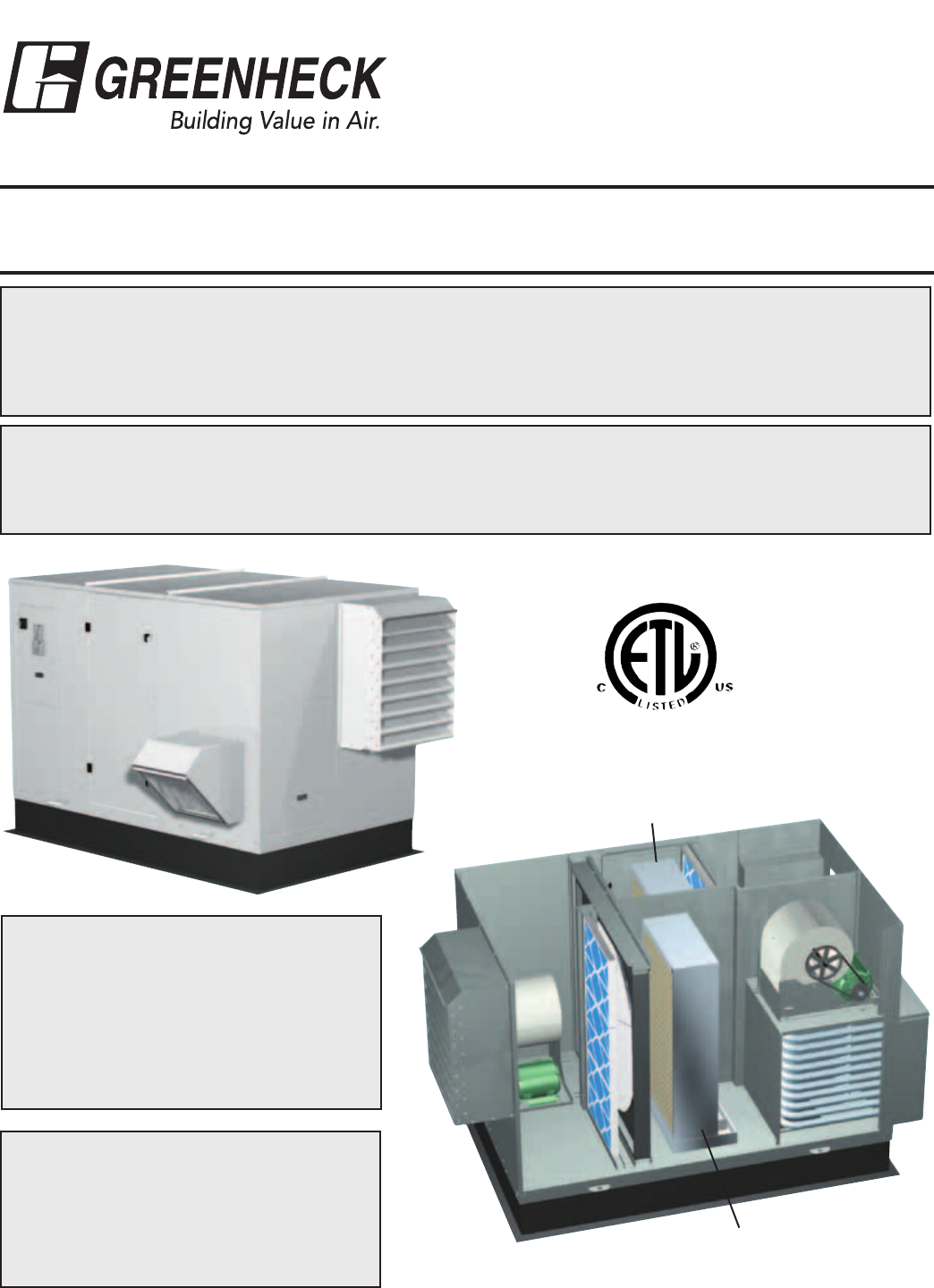
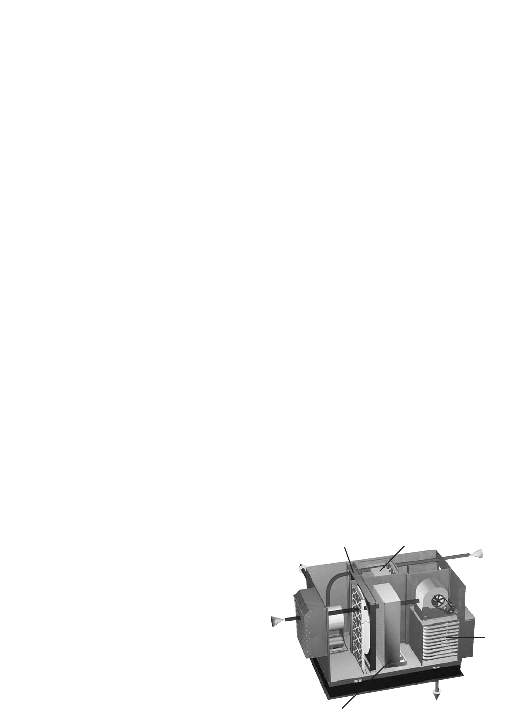
BASIC OPERATION
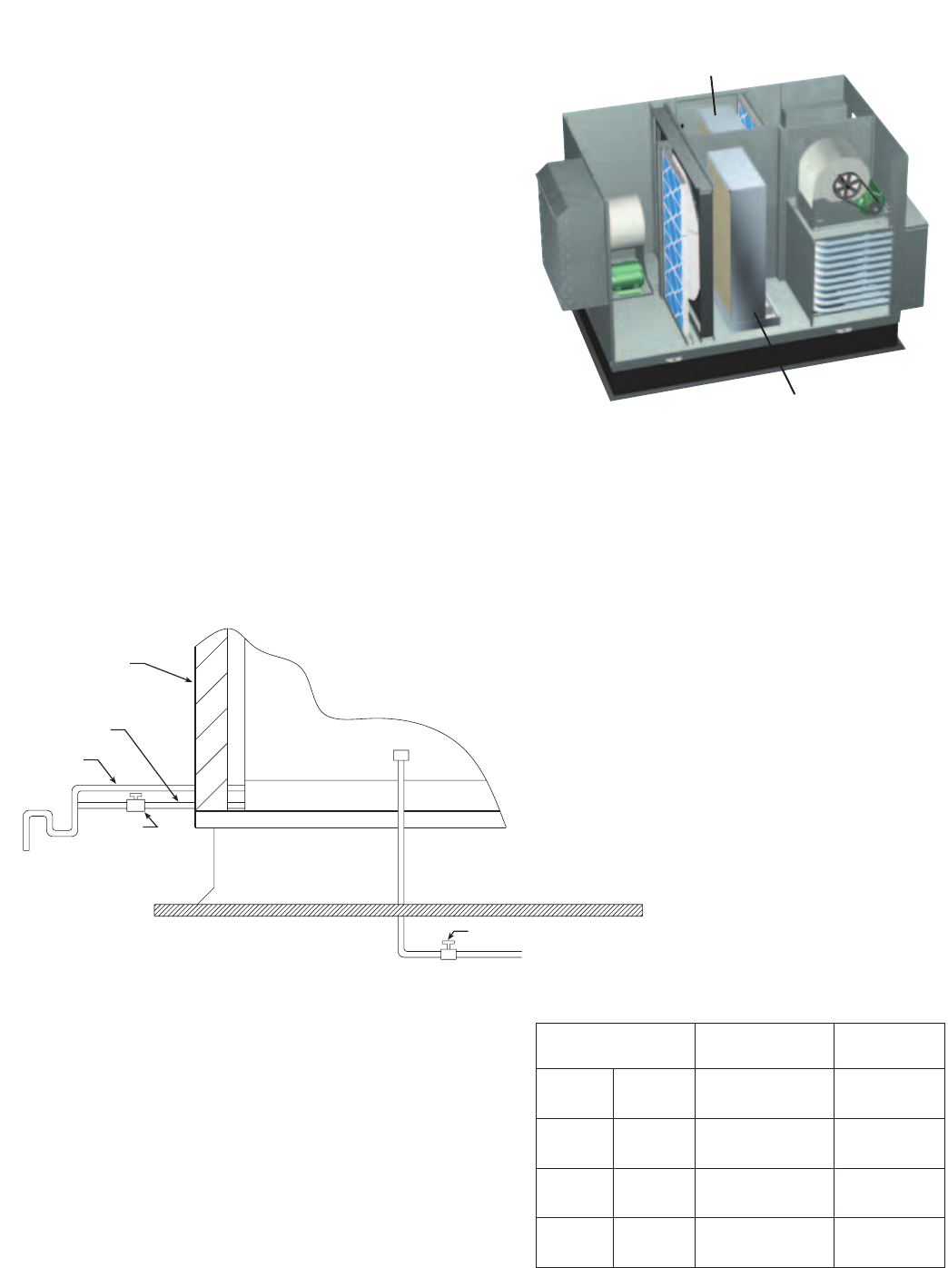
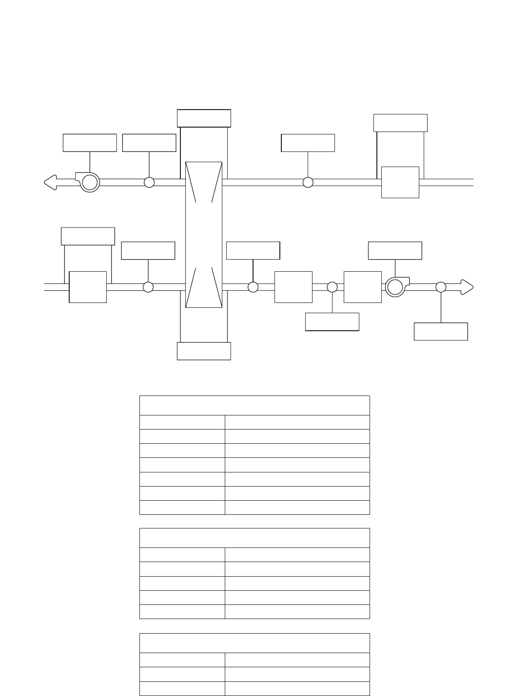
The HRE brings in fresh, outdoor air and
removes stale, exhaust air. For summer
operation, the exhaust air flows through an
evaporative cooler (indirect) to lower the
air temperature. A sensible recovery wheel
transfers energy from the exhaust air to
the outdoor air at an efficiency of 70-80%
to reduce the temperature of the outdoor
air. The outdoor air can then flow thru an
optional evaporative cooler (direct) to further
reduce the temperature of the outdoor air.
The sensible wheel also recovers heat from
the exhaust in the winter to precondition the
outdoor air. Optional heaters are available
after the wheel for final tempering.
Outdoor Air
Exhaust Air
discharged outside
Exhaust Air
from building
Conditioned Air
sent to space
Optional
Heater
Sensible
Recovery
Wheel
Indirect
Evaporative
Cooler
Direct
Evaporative
Cooler
3
INSTALLATION
The system design and installation should follow
accepted industry practice, such as described in the
ASHRAE Handbook.
Adequate space should be left around the unit for piping
coils and drains, filter replacement, and maintenance.
Sufficient space should be provided on the side of the
unit for routine service and component removal should
that become necessary.
See Service Clearances/Access Panel Locations section
for more details.
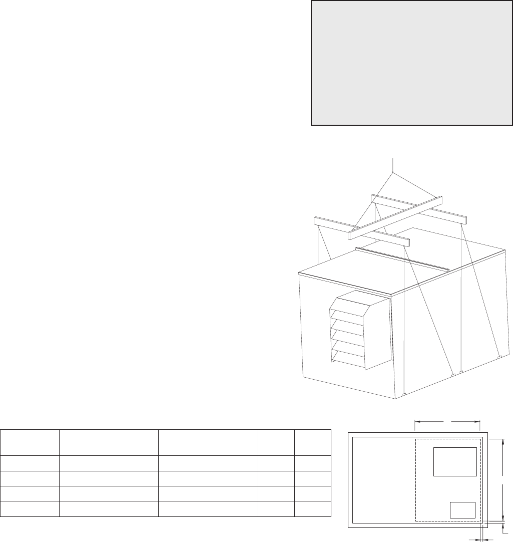
LIFTING
1) Before lifting, be sure that all shipping material has
been removed from unit.
2) To assist in determining rigging requirements,
weights are shown below.
3) Unit must be lifted by the eight lifting lugs provided
on base structure.
4) Rigger to use suitable mating hardware to attach to
unit lifting lugs.
5) Spreader bar(s) must span the unit to prevent
damage to the cabinet by the lift cables.
6) Always test-lift the unit to check for proper balance
and rigging before hoisting to desired location.
7) Neverliftunitsbyweatherhoods.
8) Neverliftunitsinwindyconditions.
9) Preparation of curb and roof openings should be
completed prior to lifting unit to the roof.
10) Check to be sure that gasketing (supplied by others)
has been applied to the curb prior to lifting the unit
and setting on curb.
11) Do not use fork lifts for handling unit.
Lift using
lifting lugs and
spreader bar
UNIT WEIGHTS & RECOMMENDED ROOF OPENING
SUPPLY
OUTLET
EXHAUST
INLET
U
V
0.50
0.50
Unit Size Approx. Dry Weight
(lbs)
Approx. Wet Weight
(lbs) U V
HRE-20 1660 1800 46 37
HRE-45 2580 2840 54 39
HRE-55 2950 3320 65 47
HRE-90 4750 5400 85 49
SAFETY WARNING
All factory provided lifting lugs must
be used when lifting the units. Failure
to comply with this safety precaution
could result in property damage,
serious injury, or death.
Unit weights assume indirect evap, direct evap, and IG furnace.
All dimensions shown are in inches.
Position the unit roof opening such that the supply discharge and exhaust inlet of the unit will line up with the
corresponding ductwork. Be sure to allow for the recommended service clearances when positioning opening
(see Service Clearances). Do not face the outdoor air inlet of the unit into prevailing wind and keep the supply
inlet of the unit away from any other exhaust fans. Likewise, position the exhaust discharge opening away from
fresh air intakes of any other equipment.
When cutting only duct openings, cut opening 1 inch (25mm) larger than duct size to allow clearance for
installation. Area enclosed by roof curb must comply with clearance to combustible materials. If the roof is
constructed of combustible materials, area within the roof curb must be ventilated, left open, or covered with
non-combustible material which has an ÒRÓ value of at least 5. If area within curb is open, higher radiated
sound levels may result.
Where the supply or warm air duct passes thru a combustible roof, a clearance of one inch must be maintained
betweentheoutsideedgesoftheductandcombustiblematerialinaccordancewithNFPAStandard90A.
4
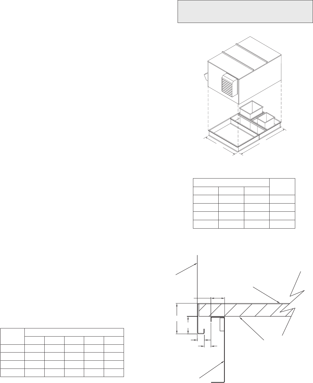
Rooftop units require curbs to be mounted first. The duct connections must be located so they will be clear of
structural members of the building.
1. Factory Supplied Roof Curbs
Roof curbs are Model GKD, which are shipped in a
knockdown kit (includes duct adapter) and require field
assembly (by others). Assembly instructions are included
with the curb.
2. Install Curb
Locate curb over roof opening and fasten in place. (Refer
to Recommended Roof Openings). Check that the diagonal
dimensions are within ±1/8 inch of each other and adjust as
necessary. For proper coil drainage and unit operation, it is
important that the installation be level. Shim as required to
level.
3. Install Ductwork
Installation of all ducts should be done in accordance with
SMACNAandAMCAguidelines.Ductadapterprovidedto
support ducts prior to setting the unit.
4. Set the Unit
Lift unit to a point directly above the curb and duct
openings. Guide unit while lowering to align with duct
openings. Roof curbs fit inside the unit base. Make sure the
unit is properly seated on the curb and is level.
L
W
All dimensions shown are in inches.
Curb Outside Dimensions
Roof curb details, including duct location
dimensions, are available on HRE roof curb
assembly instructions.
ROOF CURB
SIDE OF UNIT
BASE
1 INCH INSULATION
E
D
C
A
B
Curb Outside Dimensions Weight
Model L W
HRE-20 93 51 280
HRE-45 100.5 60.63 355
HRE-55 112.75 71.5 450
HRE-90 125.75 90.75 625
Model Curb Cap Dimensions
A B C D E
HRE-20 2.00 2.00 1.00 0.88 0.75
HRE-45 2.00 4.25 2.00 1.31 0.50
HRE-55 2.00 4.25 2.00 1.31 0.50
HRE-90 2.00 4.25 2.00 1.31 0.50
All dimensions shown are in inches.
Curb CAP Details for Factory Supplied Roof Curbs
ROOF CURB MOUNTING
5
1 Fan
Wheel
Dia.
1 Fan
Wheel
Dia.
R
o
t
a
t
i
o
n
R
o
t
a
t
i
o
n
R
o
t
a
t
i
o
n
R
o
t
a
t
i
o
n
Length of Straight Duct
GOOD
POOR
GOODPOOR
GOOD POOR
Tu rning
Vanes
Tu rning
Vanes
SYSTEM EFFECT FACTOR CURVES
FPM X 100
OUTLET VELOCITY
0 5 10 15 20 25 30 35 40 45
1.2
1.0
0.8
0.6
0.4
0.2
0.0
STATIC PRESSURE LOSS
CURVE 1
CURVE 2
CURVE 3
CURVE 4
1 Fan
Wheel
Dia.
1 Fan
Wheel
Dia.
R
o
t
a
t
i
o
n
R
o
t
a
t
i
o
n
R
o
t
a
t
i
o
n
R
o
t
a
t
i
o
n
Length of Straight Duct
GOOD
POOR
GOODPOOR
GOOD POOR
Tu rning
Vanes
Tu rning
Vanes
SYSTEM EFFECT FACTOR CURVES
FPM X 100
OUTLET VELOCITY
0 5 10 15 20 25 30 35 40 45
1.2
1.0
0.8
0.6
0.4
0.2
0.0
STATIC PRESSURE LOSS
CURVE 1
CURVE 2
CURVE 3
CURVE 4
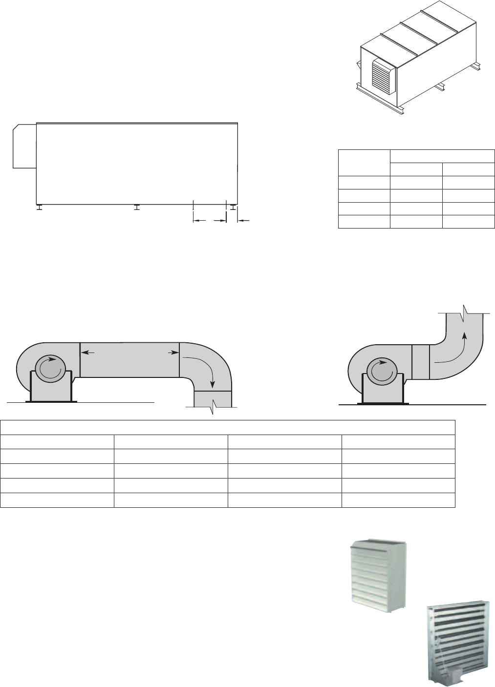
DUCTWORK CONNECTIONS
Examples of good and poor fan-to-duct connections are shown below. Airflow out of the fan should be directed
straight or curve the same direction as the fan wheel rotates. Poor duct installation will result in low airflow and
other system effects.
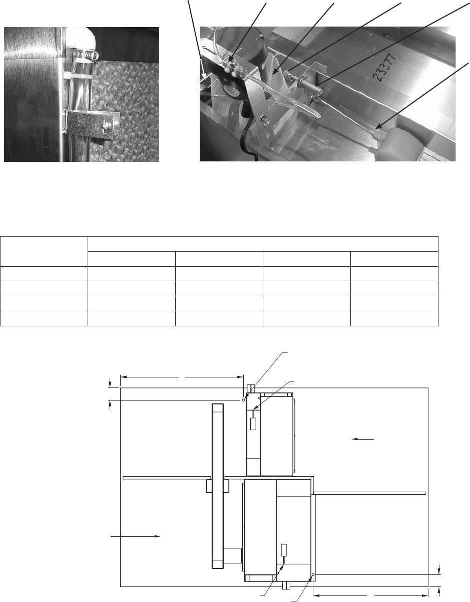
Rail Layout
• RailsdesignedtohandletheweightoftheHREshouldbe
positioned as shown on the diagram (rails by others).
• Makesurethatrailpositioningdoesnotinterferewiththesupply
air discharge opening or the exhaust air intake opening on the
HRE unit. Avoid area dimensioned “B” below
• Railsshouldrunthewidthoftheunitandextendbeyondtheunit
a minimum of 12 inches on each side.
• Setunitonrails.
AB
SUPPLY/EXHAUST
OPENING
OUTDOOR
AIR
INTAKE
HOOD
AB
SUPPLY/EXHAUST
OPENING
OUTDOOR
AIR
INTAKE
HOOD
Isometric view of HRE on rails
Side view of HRE on rails
Dimensions shown are in inches.
SUPPLY WEATHERHOOD
Supply weatherhood will be factory mounted.
EXHAUST WEATHERHOOD
The exhaust weatherhood is shipped separately as a kit with its own
instructions.
DAMPERS
Backdraft dampers are always included as an integral part of the
exhaust hood assemblies. Motorized outdoor air and exhaust air
dampers are optional and are factory mounted (and wired) at the
inlet.
RAIL MOUNTING
Recommended Discharge Duct Size and Length
HRE Model HRE Blower Size Duct Size Straight Duct Length
HRE-20 10 14 x 14 40
HRE-45 12 20 x 20 48
HRE-55 15 28 x 28 60
HRE-90 18 32 x 32 72
Model Rail Mounting
A B
HRE-20 5.1 25.0
HRE-45 7.1 25.1
HRE-55 5.7 35.0
HRE-90 6.6 36.1
All dimensions shown are in inches.

6
ELECTRICAL INFORMATION
TheunitmustbeelectricallygroundedinaccordancewiththecurrentNationalElectricalCode,ANSI/NFPA
No.70.InCanada,usecurrentC.S.A.StandardC22.1,CanadianElectricalCode,Part1.Inaddition,theinstaller
should be aware of any local ordinances or electrical company requirements that might apply. System power
wiring must be properly fused and conform to the local and national electrical codes. System power wiring is to
the unit main disconnect (door interlocking disconnect switch standard on most units) or distribution block and
mustbecompatiblewiththeratingsonthenameplate:supplypowervoltage,phase,andamperage(Minimum
Circuit Amps - MCA, Maximum Overcurrent Protection - MOP). All wiring beyond this point has been done by
the manufacturer and cannot be modified without affecting the unit’s agency / safety certification.
If field installing an additional disconnect switch, it is recommended that there is at least four feet of service
room between the switch and system access panels. When providing or replacing fuses in a fusible disconnect,
use dual element time delay fuses and size according to the rating plate.
If power supply is desired thru bottom of unit, run the wiring through the curb, cut a hole in the cabinet bottom,
and wire to the disconnect switch.
The electric supply to the unit must meet stringent requirements for the system to operate properly. Voltage
supply and voltage imbalance between phases should be within the following tolerances. If the power is not
within these voltage tolerances, contact the power company prior to operating the system.
Voltage Supply - See voltage use range on the rating plate. Measure and record each supply leg voltage at all
line disconnect switches. Readings must fall within the allowable range on the rating plate.
Voltage Imbalance - In a 3-phase system, excessive voltage imbalance between phases will cause motors
to overheat and eventually fail. Maximum allowable imbalance is 2%. To determine voltage imbalance, use
recorded voltage measurements in this formula.
Key: V1,V2,V3=linevoltagesasmeasured
VA(average)=(V1+V2+V3)/3
VD=Linevoltage(V1,V2orV3)thatdeviatesfarthestfromaverage(VA)
Formula: %VoltageImbalance=[100x(VA-VD)]/VA
Most factory supplied electrical components are pre-wired. To determine what electrical accessories require
additional field wiring, refer to the unit specific wiring diagram located on the inside of the unit control center
access door. The low voltage control circuit is 24 Vac and control wiring should not exceed 0.75 ohms. Refer to
Field Control Wiring Length/Gauge table for wire length maximums for a given wire gauge. Control wires should
not be run inside the same conduit as that carrying the supply power. Make sure that field supplied conduit
does not interfere with access panel operation.
CAUTION
If any of the original wire as supplied with the appliance must be replaced, it must be
replaced with wiring material having a temperature rating of at least 105ºC.
WARNING
To prevent injury or death due to electrocution or
contact with moving parts, lock disconnect switch
open.
WARNING
For units with a gas furnace, if you turn off the
power supply, turn off the gas.
Field Control Wiring Length/Gauge
Total Wire Length Minimum Wire Gauge
125 ft. 18
200 ft. 16
300 ft. 14
450 ft. 12
If wire resistance exceeds 0.75 ohms, an industrial-style, plug-in relay should be added to the unit control
center and wired in place of the remote switch (typically between terminal blocks R and G on the terminal strip
(refer to Typical Control Center Components). The relay must be rated for at least 5 amps and have a 24 Vac
coil. Failure to comply with these guidelines may cause motor starters to “chatter” or not pull in which can
cause contactor failures and/or motor failures.
Note: Standard factory installed electric post-heaters have their own disconnect separate from the unit
disconnect. Thus, each electric post-heater requires its own separate power connection.
7
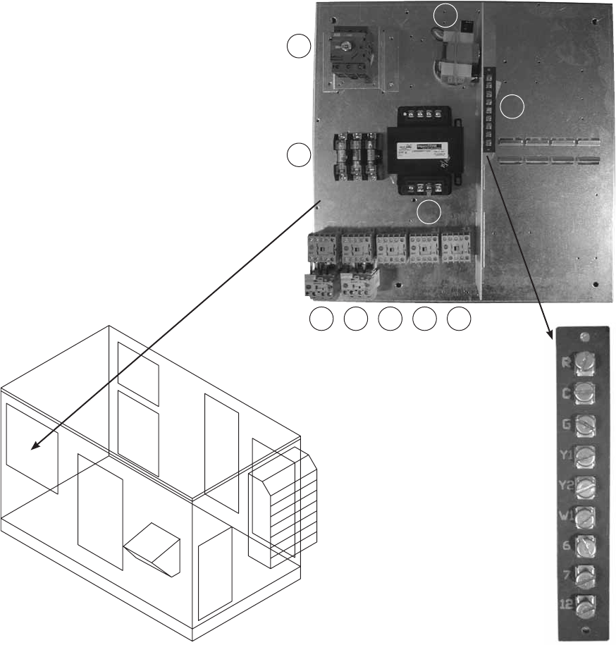
1. Main Disconnect (non-fusible, lockable)
2. Motor Starter - Exhaust Air Fan
3. Motor Starter - Outdoor Air Fan
4. Motor Contactor - Energy Wheel
5. 24 VAC Control Transformer
6. 24 VAC Terminal strip
7. Fuses for blower motors
8. Motor Contactor - Indirect Evap Pump
9. Motor Contactor - Direct Evap Pump
10. Evap Pump Transformer
(115 VAC Secondary)
TYPICAL CONTROL CENTER COMPONENTS
1
2 3 4 8 9
7
5
10
Exploded Detail
of Terminal Strip
6
8
Wheel Cassette
2 in. filters
2 in. filters
Direct
Evap
Section
Exhaust Air
Intake
Electrical Box
Access Panel
Access Panel
Access Panel
Access Panel
Access Panel
Cassette
Slides Out
52 in.
Clearance with
IG Heater
0 in.
Clearance without
IG Heater
Exhaust
Hood
Outdoor Air Hood
IG Heater
*48 in. **64 in.
36 in.
36 in.
TOP VIEW
Indirect
Evap
Section
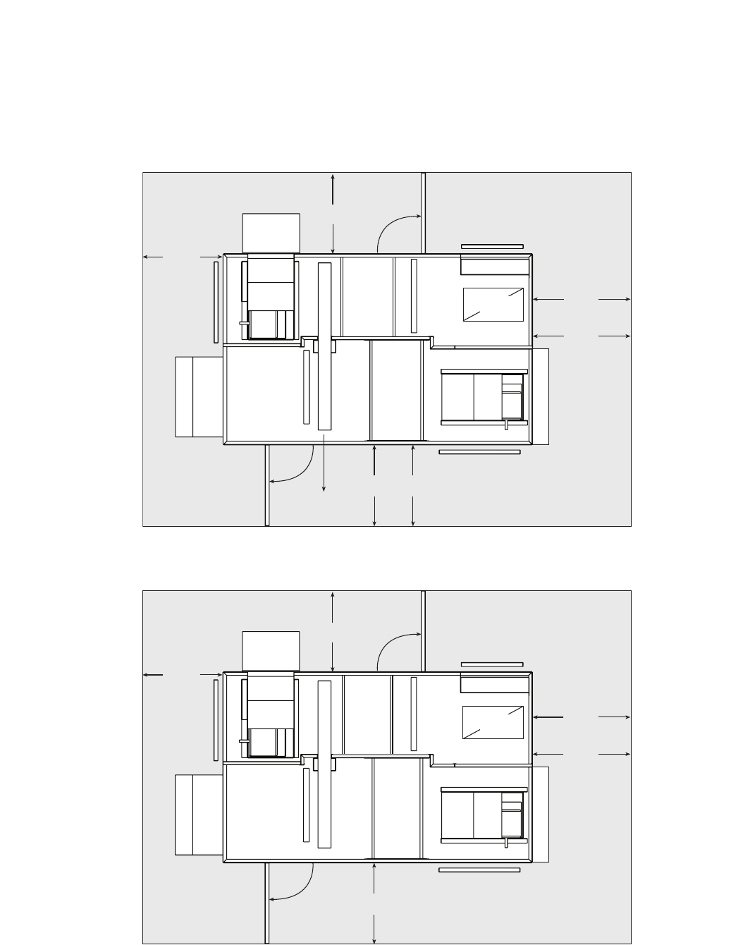
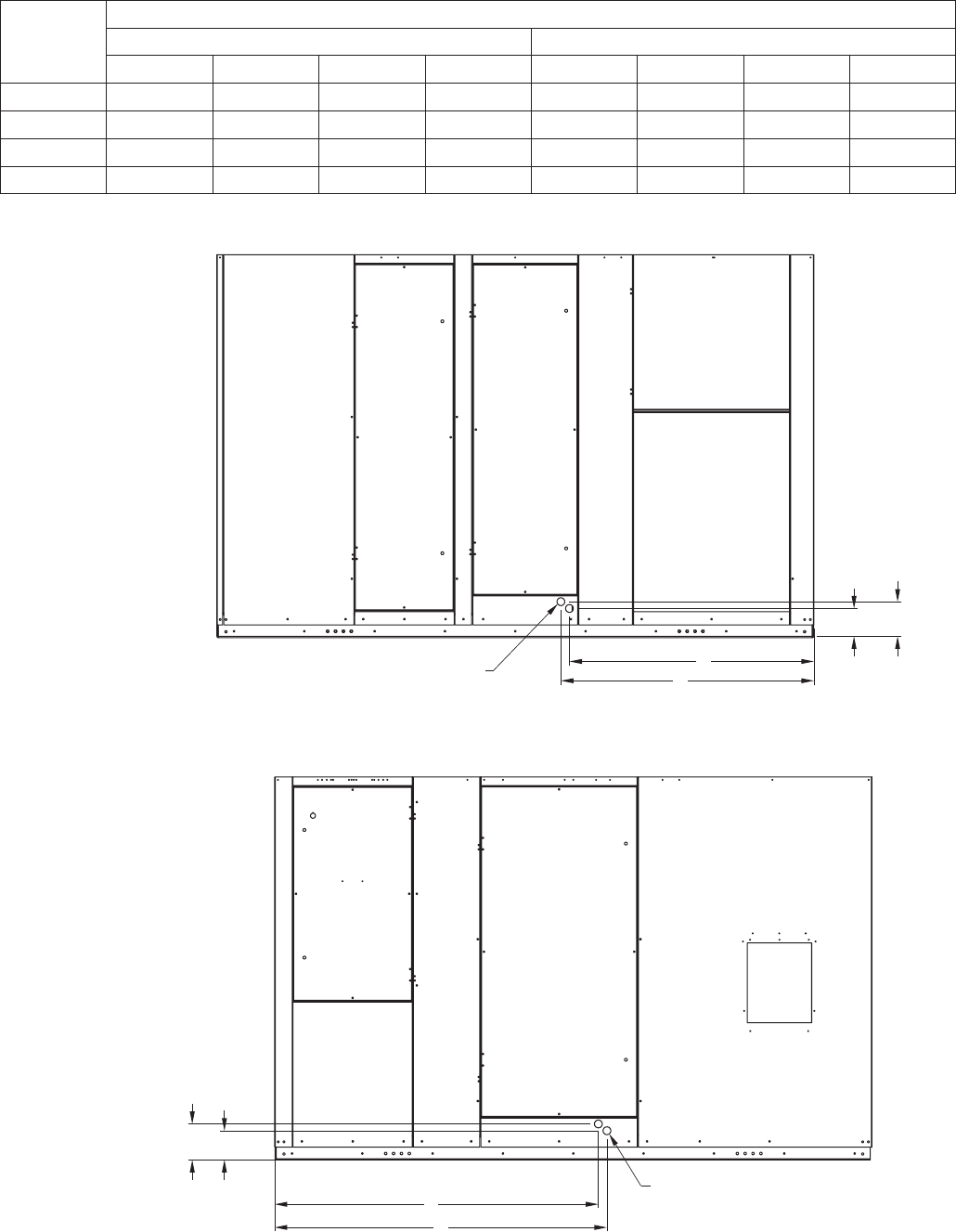
SERVICE CLEARANCES / ACCESS PANEL LOCATIONS
HRE-20, 45, 55, and 90 units require minimum clearances for access on all sides for routine maintenance. Filter
replacement, drain pan inspection and cleaning, energy wheel cassette inspection, fan bearing lubrication and
belt adjustment, are examples of routine maintenance that must be performed. Blower and motor assemblies,
energy recovery wheel cassette, coil and filter sections are always provided with a service door or panel for
proper component access. Clearances for component removal may be greater than the service clearances,
refer to drawings below for these dimensions.
Wheel Cassette
2 in. filters
2 in. filters
Exhaust Air
Intake
Electrical Box
Access Panel
Access Panel
Access Panel
Access Panel
Access Panel
52 in.
Clearance with
IG Heater
0 in.
Clearance without
IG Heater
Exhaust
Hood
Outdoor Air Hood
IG Heater
42 in.
42 in.
42 in.
TOP VIEW
Direct
Evap
Section
Indirect
Evap
Section
Clearances for service and component removal on HRE-20 and HRE-45
* Clearance for energy wheel removal on HRE-20
** Clearance for energy wheel removal on HRE-45
HRE-20
HRE-45
HRE-55
HRE-90
Clearances for service and component removal on HRE-55 and HRE-90
9
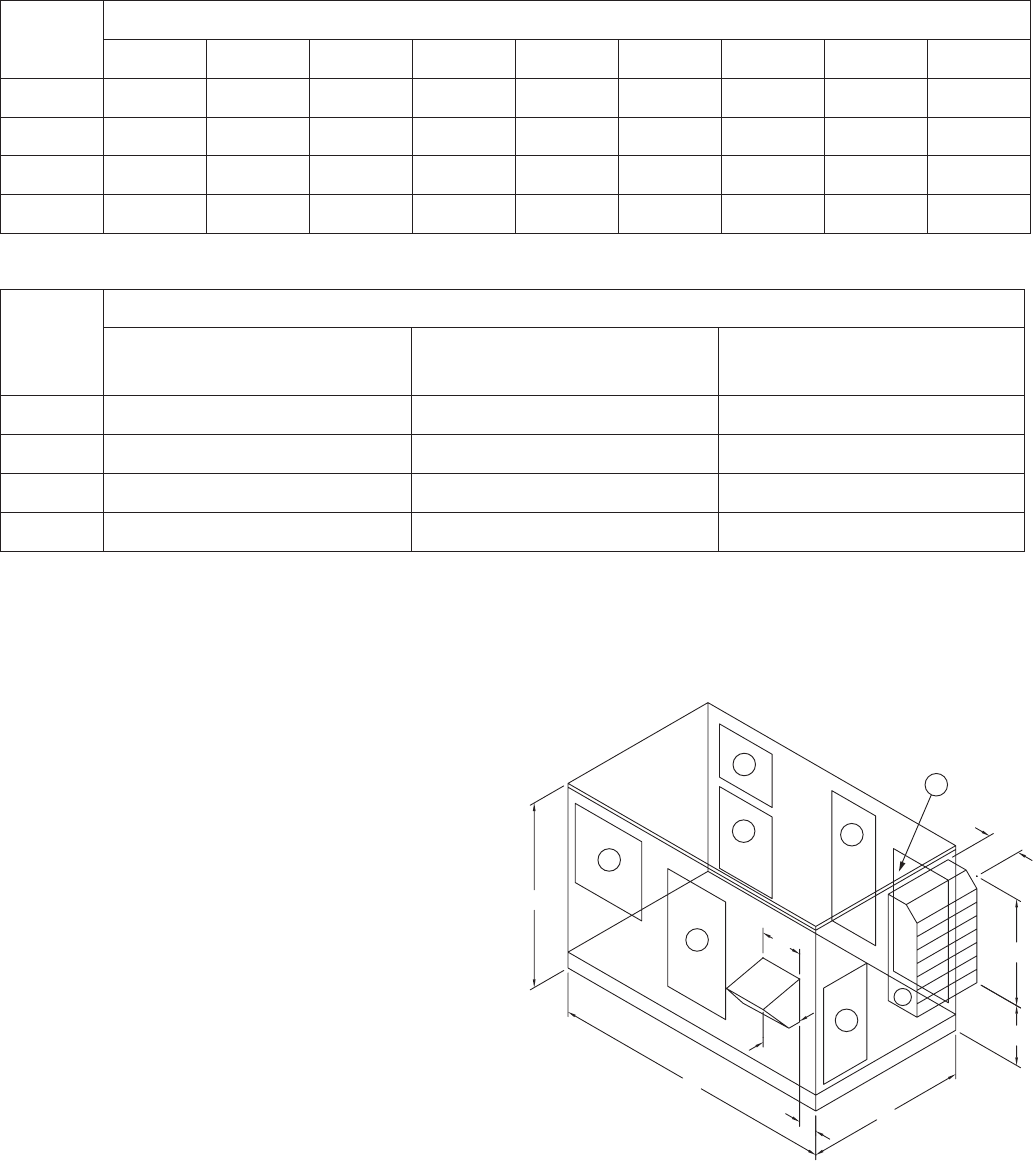
DIMENSIONAL DATA / ACCESS DOOR DESCRIPTIONS
Following is a list of items accessible through the access
doors shown on the diagram at the right. Some items are
optional and may not have been provided.
1) Exhaust blower, motor, and drives
2) Aluminum mesh filters (intake hood)
3) Energy recovery wheel, motor, belt, and seals
Outdoor air filters
Outdoor air intake damper (optional)
Electric preheater (optional)
Frost control sensors (optional)
Economizer sensors (optional)
4) Direct evaporative cooler, drain pan,
and pump (optional)
5a) Outdoor air blower, motor, and drives
(without indirect gas furnace)
5b) Outdoor air blower, motor, and drives
(with indirect gas furnace)
6) Control center
All electrical controls
VFDs for blowers (optional)
VFD for energy recovery wheel (optional)
7) Indirect evaporative cooler, drain pan, and pump
Exhaust air filters
Exhaust air intake damper (optional)
Dimensional data and
access door locations
Model
Exterior Dimensions
A B C D E F G H I
HRE-20 98 50 56 18 28.5 17 6 14.25 18
HRE-45 106 69 66 16 41 23.375 10.5 13.375 20
HRE-55 118 70 76 16 59.5 5.875 7.125 21.25 25
HRE-90 131 85 96 16 78 2.875 10 24.5 27
Model
Overall Exterior Dimensions
Width
(including Lifting Lugs)
Overall Width
(with Exhaust Hood)
Overall Length
(with Outdoor Air Hood)
HRE-20 59.5 75 116
HRE-45 69.5 86 122
HRE-55 79.5 101 134
HRE-90 99.5 123 147
All dimensions shown are in inches.
All dimensions shown are in inches.
A
I
C
B
D
E
F
G
H
1
2
5b
3
5a 4
6
7
10
1. After the energy recovery unit is set in place, run the
overflow and drain lines to the exterior fittings on the
evaporative cooler (drain & overflow connections at
unit are 1-inch male pipe thread). The supply line can
be attached at the downstream side of the evaporative
cooler. A manual shut off valve should be mounted in
the supply line near the unit for servicing purposes.
Also, a trap should be installed in the drain line to
prevent air/sewer gas from being drawn into the unit
(refer to Drain and Overflow Connection Locations and
Drain Trap sections). Run bleed line into overflow.
EVAP MODULE START-UP
1. The cooler will be prewired by the factory. (pumps are 115VAC).
2. Check to make sure that the pump filter is around the pump inlet.
3. Turn the water on and allow the sump to fill. Adjust the float valve to shut-off the water supply when the
sump is filled to a 1-inch height.
4. Open the bleed-off valve completely and saturate the media without any airflow through the unit. A jumper
wire is required on the terminal strip to provide power to the evaporative cooler pump (see the wiring
diagram for the proper location). This saturation process will break-in the media and minimize the odors
associated with the media. The media’s break-in period should
be no less than 20 minutes. When the process is complete,
remove the jumper wires in the control center.
Note:Evaporativemediamayfoamforashortperiod
following the initial start-up. Leave the bleed-off
valve fully open until the foaming stops.
5. After the media break-in period, the
water flow rate over the media needs to be
checked. The pumps should provide enough
water to saturate the media in 1-3
minutes. If adequate flow rate is
not achieved, adjust via water
flow adjustment device found on
water supply line running to evap
header.
6. The water bleed-off rate will now need to be adjusted.
This measurement is 3 to 6 percent of the media flow
rate. The recommended flow rate is 11/2 to 2 GPM
per square foot of media pad top area (see table at
right). Actual water to the unit will be based on the
evaporation rate. A water flow adjustment device is
supplied and installed by Greenheck for ease of water
flow adjustments. After the unit has been installed and
running for two weeks the unit should be checked for
mineral deposits. If there are deposits, the bleed-off
rate needs to be increased. Some areas of the country
have water with greater amounts of dissolved minerals
requiring a higher bleed-off rate.
Mount the heat recovery unit level to ensure proper
operation and water drainage. Piping should be of
adequate size to provide sufficient supply of water to meet
the maximum demand of the evaporative coolers.
EVAP MODULE INSTALLATION
EVAPORATIVE COOLING MODULES
Indirect Evaporative Cooler
(Exhaust/Scavenger Airstream)
Direct Evaporative Cooler
(Outdoor/Supply Airstream)
Roof Curb
Roof Line
Drain
Line
Trap
Overflow
Drain Line
Manual
Shutoff
Valve
Evaporative
Cooling
Media
Manual Shutoff Valve
Supply Line
Sump
Side of HRE Unit
Standard Trap and Supply Line Configuration
Media Size
(w x h x d) (in.)
Media Pad
Top Area
HRE-20 Supply
Exhaust
18 x 36 x 12
18 x 36 x 12
1.5 ft2
1.5 ft2
HRE-45 Supply
Exhaust
30 x 48 x 12
24 x 48 x 12
2.5 ft2
2.0 ft2
HRE-55 Supply
Exhaust
36 x 56 x 12
30 x 56 x 12
3.0 ft2
2.5 ft2
HRE-90 Supply
Exhaust
48 x 69.5 x 12
40 x 69.5 x 12
4.0 ft2
3.3 ft2
11
7. Verify that both airflow and system static pressure are in agreement with the specifications. If these
conditions are met, check for water carry over from the discharge side of the media. If carry over is
observed, check the distribution header for holes or tears and the water standoff tube for blockage.
8. After all final adjustments are made, remove the jumper wires, connect “call for cooling” signal, and replace
all access panels. The unit is now ready for operation.
Bleed-Off
Valve
Overflow Pump
Filter
Threaded
Float
Adjustment
Supply
Connection
Float
Valve
Pump and Float Components
HRE WATER SUPPLY CONNECTION LOCATION
B
A
Ø0.875
Run 1/4 inch line up through 7/8 inch
hole here and bring around end
of sump to supply connection.
D
C
Ø0.875
Run 1/4 inch line up through 7/8 inch
hole here and bring around end
of sump to supply connection.
OA INLET
EA INLET
1/4 inch Water Supply Connection
1/4 inch Water Supply Connection
Model Water Supply Connection Locations
A B C D
HRE-20 37.375 4.625 4.625 39.25
HRE-45 38.75 4.625 4.625 43.00
HRE-55 43.50 4.625 4.625 46.125
HRE-90 43.50 4.625 4.625 52.625
Dimensions from outside of unit (in inches)
Top View
Water Flow Adjustment Device
12
Evaporative
Timer
Evaporative
Freeze
Protection
t2 settings
t1 settings
Temperature
Setting
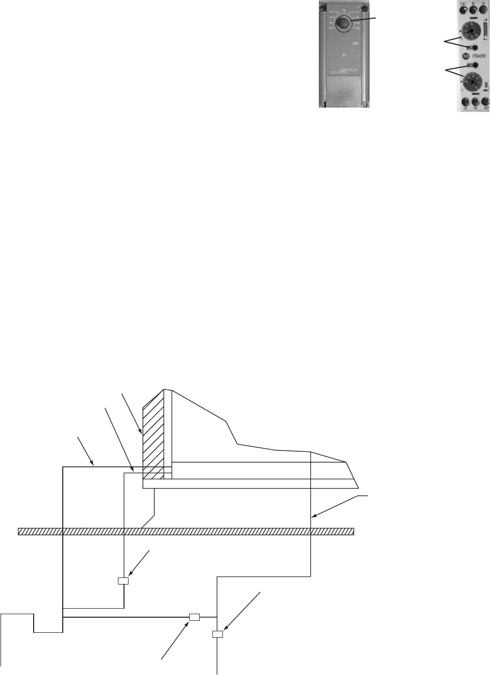
AUTO DRAIN AND FILL WITH FREEZE PROTECTION
This system will automatically drain the sump tank and fill it with
fresh water at the field adjustable intervals, typically once every 24
hours. This flushes mineral build-up and debris from the tank to
promote low maintenance and increase media pad life. In addition,
the system will protect the evaporative cooler from freezing
by draining the sump tank and supply line when the outside
temperatures fall below the set point of the outside air sensor.
Typically, this is set at 45º to 50º F. The auto drain and fill outdoor
air sensor should be installed in an area that is shaded from direct
sunlight so the outside air sensor probe will detect an accurate air
temperature.Setthetimer.Timersettingsaret1:1.0,10minand
t2:0.4,60h
PLUMBING FOR AUTO DRAIN AND FILL
1. Run water supply line to the unit and install Water Supply Solenoid Valve (A) in this line as close to the
water source as possible.
2. Install Drain Solenoid Valve (B) in the supply line as indicated below. From the outlet on the drain valve,
run line to a suitable drain location.
3. Run an unobstructed drain line from the sump overflow to the drain trap as shown below.
4. Install Sump Drain Solenoid Valve (C) in the drain line from the sump as indicated below. From the outlet
on this drain valve, run a line to a suitable drain location.
Note: Water Supply Solenoid Valve (A) is not the same as the Drain Solenoid valves (B) and (C). Make sure to
use the proper valve for each location. Check your local code requirements for proper installation of this
type of system. Additional drain and supply plumbing may be needed to meet your local code.
Caution: All solenoid valves A, B, and C must be installed below the roof to protect the supply water line from
freezing. If these valves cannot be installed below the roof, an alternate method must be used to protect these
lines from freezing.
WATER CONTROL OPTIONS FOR EVAPORATIVE COOLING
Trap & Supply Line Configuration
with Auto Drain and Fill
A1
B1
15
NC
JC
COM
TIMER
JC
18
A2
16
VC
VB
VA
JOHNSON CONTROLLER
24VAC COMSENSOR
24V AC POWER AND WIRING
BY OTHERS
SENSOR
OUTDOOR AIR
VALVE "A"
VALVE "B"
VALVE "C"
TIMER
OUTDOOR AIR SENSOR
T1
AUTO DRAIN AND FILL WITH FREEZE PROTECTION
PART DESCRIPTIONS
VALVE, WATER SUPPLY (A)
VALVE, DRAIN (B)
VALVE, SUMP DRAIN (C)
24 HOUR TIMER
JOHNSON CONTROLLER
GREENHECK P/NQTY.
07458032 1
07381940 1
05461262 1
05461263 1
05461264 1
OUTDOOR AIR SENSOR 07458298 1
1/2 PIPE SIZE (NC)
1/4 PIPE SIZE (NO)
3/4 PIPE SIZE (NO)
-
25
25
25
-
-
HOLDING VA INRUSH VA
-
70
50
70
-
-
SUMP
EVAPORATIVE
COOLING MEDIA
ROOF CURB
ROOF LINE
TRAP
DRAIN LINE
SUPPLY LINE
WATER SUPPLY SOLENOID VALVE (A)–NORMALLY CLOSED
1/2 INCH PIPE SIZE
DRAIN SOLENOID VALVE (B)–NORMALLY OPEN
1/4 INCH PIPE SIZE
SUMP DRAIN SOLENOID VALVE (C)–NORMALLY OPEN
3/4 INCH PIPE SIZE
SIDE OF HRE UNIT
SUMP DRAIN PIPE
(TO EACH EVAP)
SUMP OVERFLOW PIPE
(TO EACH EVAP)
THE SYSTEM WILL AUTOMATICALLY DRAIN THE SUMP TANK AND FILL IT WITH FRESH WATER AT THE FIELD ADJUSTABLE INTERVALS, TYPICAL SETTINGS ARE t1 = 24HRS
t2 = 10 MIN. WITH THE DIP SWITCH IN THE DOWN POSITION. THIS FLUSHES MINERAL BUILD-UP AND DEBRIS FROM THE TANK TO PROMOTE LOW MAINTENANCE AND
INCREASE MEDIA PAD LIFE. IN ADDITION, THE SYSTEM WILL PROTECT THE EVAPORATIVE COOLER FROM FREEZING BY DRAINING THE SUMP TANK AND SUPPLY LINE
WHEN THE OUTSIDE TEMPERATURES FALL BELOW THE SET POINT OF THE OUTDOOR AIR SENSOR. TYPICALLY, THIS IS SET AT 45° TO 50° F. THE AUTO DRAIN AND FILL
OUTDOOR AIR SENSOR SHOULD BE INSTALLED IN AN AREA THAT IS SHADED FROM DIRECT SUNLIGHT SO THE SENSOR PROBE WILL DETECT AN ACCURATE AIR
TEMPERATURE.
THE FOLLOWING COMPONENTS SHIP FROM GREENHECK WITH HRE (INSTALLATION, WIRING, AND POWER BY OTHERS)
WATER LINE CONNECTION
AT FLOAT IS 1/4 INCH
13
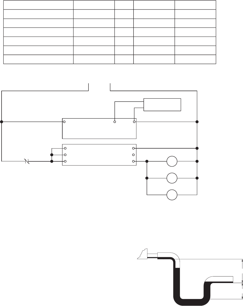
Coolingcoilsareprovidedwithastainlesssteeldrainpanwith3/4-in.femaleNPTdrainconnection.Adrain
trap must be connected to the drain connection to allow excess water to flow out of the drain pan. More
importantly, though, due to the negative internal static of the cooling coil compartment, installing the drain trap
prevents outdoor air from being pulled into the drain pan and consequently forcing water out of the pan and
into the unit.
To ensure the drain trap works properly, the trap height must account for the difference in static pressure
between ambient conditions outside the unit and the internal
negative pressure of the cooling coil compartment. For energy
recovery units, an assumption of 3.0 in. wg. differential will be
sufficient. This would require a trap design as shown. If the
internal static is believed to be higher, consult factory.
Refer to local codes to determine drainage requirements. If
draining onto to roof, place a drip pad below drain to protect
roof. If draining onto roof is not acceptable, a drain line must be
attached to the trap. The drain line must be pitched away from
the unit at least 1/8-in. per foot. On longer runs, an air break should be used to ensure proper drainage. Local
codes may require drainage into a waste water system.
Drainage problems not only occur from improper drain trap design, but also from lack of maintenance of the
cooling coil compartment. Algae can form in the drain pan and trap and cause reduced water flow, which can
in turn result in backup into the system. Regular maintenance will prevent this from occurring. If the drains have
a cleanout opening, be sure to close the opening after cleaning.
A1
B1
15
NC
JC
COM
TIMER
JC
18
A2
16
VC
VB
VA
JOHNSON CONTROLLER
24VAC COMSENSOR
24V AC POWER AND WIRING
BY OTHERS
SENSOR
OUTDOOR AIR
VALVE "A"
VALVE "B"
VALVE "C"
TIMER
OUTDOOR AIR SENSOR
T1
AUTO DRAIN AND FILL WITH FREEZE PROTECTION
PART DESCRIPTIONS
VALVE, WATER SUPPLY (A)
VALVE, DRAIN (B)
VALVE, SUMP DRAIN (C)
24 HOUR TIMER
JOHNSON CONTROLLER
GREENHECK P/NQTY.
07458032 1
07381940 1
05461262 1
05461263 1
05461264 1
OUTDOOR AIR SENSOR 07458298 1
1/2 PIPE SIZE (NC)
1/4 PIPE SIZE (NO)
3/4 PIPE SIZE (NO)
-
25
25
25
-
-
HOLDING VA INRUSH VA
-
70
50
70
-
-
SUMP
EVAPORATIVE
COOLING MEDIA
ROOF CURB
ROOF LINE
TRAP
DRAIN LINE
SUPPLY LINE
WATER SUPPLY SOLENOID VALVE (A)–NORMALLY CLOSED
1/2 INCH PIPE SIZE
DRAIN SOLENOID VALVE (B)–NORMALLY OPEN
1/4 INCH PIPE SIZE
SUMP DRAIN SOLENOID VALVE (C)–NORMALLY OPEN
3/4 INCH PIPE SIZE
SIDE OF HRE UNIT
SUMP DRAIN PIPE
(TO EACH EVAP)
SUMP OVERFLOW PIPE
(TO EACH EVAP)
THE SYSTEM WILL AUTOMATICALLY DRAIN THE SUMP TANK AND FILL IT WITH FRESH WATER AT THE FIELD ADJUSTABLE INTERVALS, TYPICAL SETTINGS ARE t1 = 24HRS
t2 = 10 MIN. WITH THE DIP SWITCH IN THE DOWN POSITION. THIS FLUSHES MINERAL BUILD-UP AND DEBRIS FROM THE TANK TO PROMOTE LOW MAINTENANCE AND
INCREASE MEDIA PAD LIFE. IN ADDITION, THE SYSTEM WILL PROTECT THE EVAPORATIVE COOLER FROM FREEZING BY DRAINING THE SUMP TANK AND SUPPLY LINE
WHEN THE OUTSIDE TEMPERATURES FALL BELOW THE SET POINT OF THE OUTDOOR AIR SENSOR. TYPICALLY, THIS IS SET AT 45° TO 50° F. THE AUTO DRAIN AND FILL
OUTDOOR AIR SENSOR SHOULD BE INSTALLED IN AN AREA THAT IS SHADED FROM DIRECT SUNLIGHT SO THE SENSOR PROBE WILL DETECT AN ACCURATE AIR
TEMPERATURE.
THE FOLLOWING COMPONENTS SHIP FROM GREENHECK WITH HRE (INSTALLATION, WIRING, AND POWER BY OTHERS)
WATER LINE CONNECTION
AT FLOAT IS 1/4 INCH
4 in.
2 in.
DRAIN TRAP
14
DRAIN AND OVERFLOW CONNECTION LOCATIONS
Model
Connection Locations - in inches
Outdoor Air Side Exhaust Side
A B C D A B C D
HRE-20 4.00 2.875 40.75 42.25 4.00 2.875 52.25 53.75
HRE-45 6.25 5.125 42.625 44.125 6.25 5.125 56.50 58.00
HRE-55 6.375 5.125 53.00 54.50 6.375 5.125 66.375 67.875
HRE-90 6.375 5.125 47.25 48.50 6.375 5.125 71.00 72.25
D
C
AB
3/4 INCH INDIRECT EVAP DRAIN AND
OVERFLOW CONNECTIONS
EXHAUST AIR
DISCHARGE
COMPARTMENT
EXHAUST AIR
INTAKE
COMPARTMENT
Exhaust
C
D
BA
OUTDOOR AIR
DISCHARGE
COMPARTMENT
OUTDOOR
AIR
INTAKE
COMPARTMENT
3/4 INCH DIRECT EVAP DRAIN AND
OVERFLOW CONNECTIONS
Outdoor Air
15
Symptom Solution
Leaving Air
Entering Air
45
°
15
°
Insufficient water
volume or recirculation
pump not operating
Irregular water
distribution on cooling
media
Scale and mineral
deposit formation on
face of media
Excessive water
discharge into drain
Water Carry-Over
Poor performance
after cooling pad
replacement
Inadequate cooling
A. Check water level in base pan. The
level should be at 1 inch.
B. Check the pump filter at the inlet.
Clean the filter if clogged or dirty.
C. If pump is not operating, check
wiring for loose connections and
proper voltage.
D. Clogged or worn out pump.
E. Clogged header.
F. Water flow adjustment device
Water distribution header, orifices or media partially blocked or plugged.
Remove evaporative cooler from unit.
Disassemble and clean distribution header, orifices and media.
A. Increase bleed rate.
B. Increase water flow rate. Media is self-cleaning with flow rate of 11/2 to 2
gpm per square foot of media top area. Generally this flow rate prevents
dissolved solvents from collecting on the media. To prevent further
trouble, flush and clean the system more frequently.
C. Check water flow across the face of the media. Irregular water distribution
must be corrected (see above)
D. If this condition persists, chemicals may need to be added. Water pH
should be maintained between 6 and 8.
A. Irregular water distribution on face of media (see above).
B. Average face velocity exceeds 550 fpm. Decrease fan rpm and airflow.
C. Localized face velocities exceeding 550 fpm. Air filters or media face area
is partially blocked. Clean or replace air filters and media.
D. Check the overflow for blockage.
A. Irregular water distribution over face of media (see above).
B. Check for uniform airflow.
C. Check outside wet-bulb temperature. High wet-bulb temperatures can
decrease performance.
D. Check water flow rate over media. Flow rate should be 11/2 to 2 gpm per
square foot of media top area.
A. Check the water bleed off rate and make sure that it is not excessive.
B. Check water level in base pan. The level should be at 1 inch.
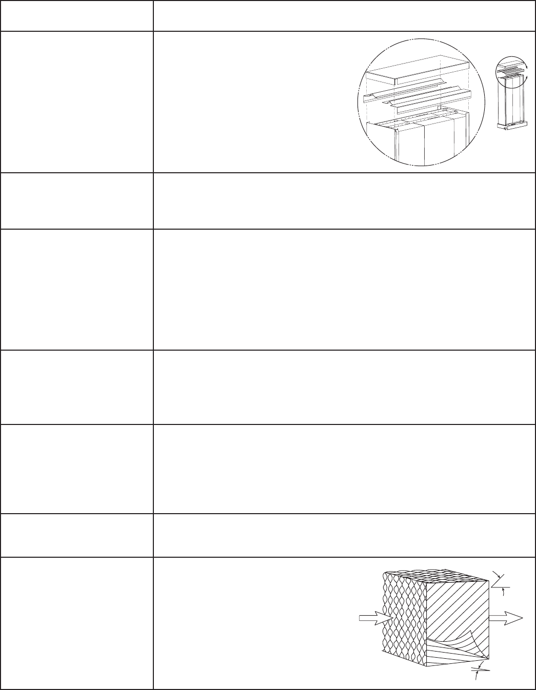
Pad installed backwards. To get the
performance from the cooling pads,
they must be installed properly. The
pads are manufactured with 15/45
degree flute angles. The pads must
always be installed with the steeper
flute angle sloping down toward the
entering air side. See figure on right.
TROUBLESHOOTING FOR EVAPORATIVE MODULE
C
Header
Detail

16
Regularly scheduled maintenance is the key to peak
performance, minimized cost, and extended life of
the evaporative cooler. The following is a checklist of
items that need to be looked at on a regular basis.
1. The media should be checked for mineral and
foreign material deposits that have built up. If
these items are left on the media, the life and
performance of the unit will be greatly reduced.
Also, there are risks of water carryover when
this type of condition exists. When signs of
mineral build-up are noticed, you should increase
the bleed off rate. If this does not solve the
problem, chemicals may need to be added to
the water. The evaporative pads tend to be self-
cleaning. Depending on water quality and system
maintenance, the useful life of the pads should
be 3 to 5 years.
2. The media should be periodically brushed lightly
with a soft bristle brush in an up and down
motion (never brush side-to-side) while flushing
with water. This will also aid in reducing the
amount of foreign material build-up.
3. The water should be shut off and all the lines
drained when the temperature drops below 50ºF.
4. When the evaporative cooler is going to be used
for the first time each season, it is recommended
that the media be flushed with clean water for a
period of 2 minutes (see Evap Module Start-Up).
5. At the beginning of each cooling season, the
upright recirculating pump should have the
shaft oiled and spun to eliminate the potential of
seizing and pump burn out.
6. If the cooling media was removed from the
unit, check to make sure that is not installed
backwards. If the media is installed backwards,
there will be large amounts of water carry
over downstream of the evaporative cooler.
Continuous operation in this manner may cause
serious damage and void the warranty.
7. At the end of each cooling season the
evaporative cooler should be thoroughly
cleaned. A dispersant and biocide (consult water
treatment consultant for suitable materials and
dosage levels) should be recirculated for 12 to 24
hourspriortoperformingthefollowingsteps:
a) Disconnect power to unit.
b) Shut off all water to the unit
c) Open evaporative cooling section door
d) Flush distribution headers and media for 20
minutes
e) Turn off pumps and drain all water distribution
piping, headers, etc.
f) Dry media completely by running blowers.
g) Brush media as described in Paragraph 2 and
perform steps d and e again.
h) Clean all remaining components (i.e. sump,
pump, etc.) of any mineral deposits or foreign
materials
i) Replace all worn or non-functioning parts
j) Reassemble the cooling unit.
k) Close cooling section door.
l) Turnthemaindisconnect‘ON’,leavingthe
cooling switch in the ‘OFF’ position.
8. If the evaporative cooler will be turned off during
the cooling season for an extended period of
time, it is recommended that the media be dried
out. This can be accomplished by allowing the
blowers to continue to run for 1-2 hours. Doing
so, will prevent organic build-up on the media
and subsequent odors getting into the space.
9. Media should be permitted to dry once per week
by allowing the blowers to run for 1-2 hours.
10. A flush cycle should be performed weekly for one
hour with the fans off.
To remove media, disconnect water line to evap
header as shown below. Then slide media section
out of unit. Sump will remain in unit. If media is wet,
turn off water supply, then turn on unit and allow air
to flow thru media for 10 -20 minutes. This will dry the
media out and make it lighter and easier to handle.
EVAPORATIVE COOLING MAINTENANCE
IMPORTANT
Replacement media should be from the same
manufacturer and be the same size as the original
media provided with the unit.
17
Electric Heater Application/Operation
Factory installed electric heaters can be provided for preheat and/or post-heat. An electric preheater warms
the outdoor air prior to the energy recovery wheel to prevent frosting on the wheel. An electric post-heater
warms the air leaving the energy recovery wheel to a user specified discharge temperature. Electric heaters are
available in 208, 230, or 460 Vac (refer to heater nameplate for voltage).
Preheaters: Preheaters are standard as 2-stage, step control. Step control heaters are designed with
multiple stages made up of equal increments of heating capability. For example, a 10 kW
heater with two stages will be composed of two 5-kW stages. Preheaters are single point
wired at the factory. A temperature sensor (with field adjustable set point) is mounted in the
outdoor airstream after the preheater to turn the preheater on. See Frost Control Application
/Operation for typical set points. If the temperature falls below the set point, the first stage of
the preheater will turn on. If the first stage does not satisfy the set point, the second stage will
also turn on.
Post-heaters: Post-heaters are standard as SCR control. Post-heaters are not single point wired (see
Electrical Connections). A temperature sensor (with field adjustable set point) is mounted in
the outdoor airstream after the post-heater to turn the post-heater on. A SCR heater provides
an infinitely modulating control of the heat to provide an accurate discharge temperature. A
call for heat is required.
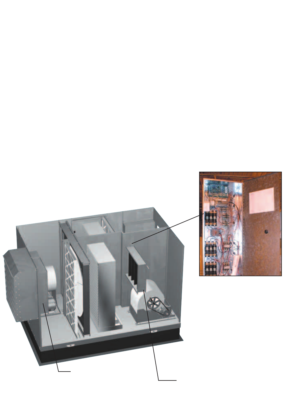
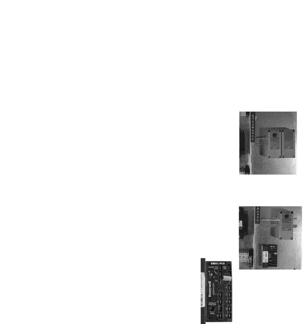
Electric Post-Heater
Post-Heater Control Panel
The post-heater is not single point
wired to the HRE control center.
Separate power must be supplied
to the post-heater disconnect
(located in unit control center).
Access to the post-heater control
panel is through the exhaust filter
door. The indirect evaporative
cooling media must be removed
from the unit along with the exhaust
filters to access.
Electric Preheater
The preheater is single
point wired to the HRE
control center. Access to the
preheater control panel is
through the supply filter door.
OPTIONAL ACCESSORIES
18
Frost Control Application/Operation
Extremely cold outdoor air temperatures can cause moisture condensation and frosting on the energy recovery
wheel.Frostcontrolisanoptionalfeaturethatwillprevent/controlwheelfrosting.Threeoptionsareavailable:
1) Timed Exhaust frost control
2) Electric preheat frost control
3) Modulating wheel frost control
All of these options are provided with a thermostat (with
probe) mounted in the outdoor air inlet compartment and
a pressure sensor to monitor pressure drop across the
wheel. The typical temperature setting corresponds to the
indoor air relative humidity as shown in the Frost Threshold Temperatures Table and represents when frost can
occur. An increase in pressure drop would indicate that frost is occurring. Both the pressure sensor AND the
outdoor air temperature sensor must trigger in order to initiate frost control. The two sensors together insure
that frost control is only initiated during a real frost condition. Field wiring of a light (or other alarm) between
6 & C in the control center will notify personnel when unit is in frost control mode (refer to Remote Panel Wiring
schematics section for wiring details). The following explains the three options in more detail.
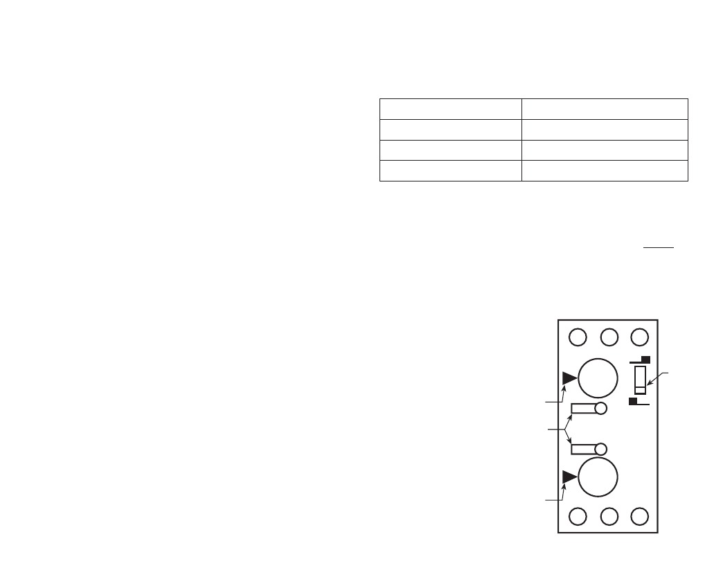
Timed exhaust frost control includes a timer in addition to the thermostat
and pressure sensor. When timed exhaust frost control is initiated, the timer
will turn the supply blower on and off to allow the warm exhaust air to defrost
the energy recovery wheel. Default factory settings are 5 minutes off and 30
minutes on. Use the following test procedure for troubleshooting.
Testing (refer to diagram at right)
• Jumperthepressureswitch.SettheTimerScaleforT1andT2to
1 minute. Set the Timer Settings for T1 and T2 to 1.0. Set the dip
switch to the down position.
• Turnthetemperaturesensorupashighaspossible.Thesupplyblower
should cycle on for one minute, then turn off for one minute.
• Aftertesting,settheTimer Scaleasfollows:T1=10minutes,T2=
1 hour
• SettheTimer Settingsasfollows:T1=0.5,T2=0.5.Thetimerisnow
set for 5 minutes off and 30 minutes on. Remember to remove the jumper.
Electric preheat frost control includes an electric heater (outdoor air inlet) and an air pressure switch
(outdoor air outlet) in addition to the thermostat and pressure sensor on wheel. (Refer to Electric Heater
Application/Operation for electric preheater location). When electric preheat frost control is initiated, the electric
preheater will turn on and warm the air entering the energy wheel to avoid frosting. Use the following test
procedure for troubleshooting.
Testing
• Turnthethermostatashighasitwillgoandjumperthewheelpressuresensor.Theheater
should turn on.
• Ifitdoesn’t,eitherputthesupplysidedoorsonortemporarilyjumpertheairpressureswitchto
avoid nuisance tripping of the pressure switch. Remember to remove the jumpers.
Modulating wheel frost control includes a variable frequency drive in addition to the thermostat and pressure
sensor. When modulating wheel frost control is initiated, the variable frequency drive will reduce the speed
of the wheel reducing the speed of the energy wheel reduces its effectiveness, which keeps the exhaust air
condition from reaching saturation, thus, eliminating condensation and frosting. If the outdoor air temperature is
greater than the frost threshold temperature OR the pressure differential is less than the setpoint, the wheel will
runatfullspeed.IftheoutdoorairtemperatureislessthanthefrostthresholdtemperatureANDthepressure
differential is greater than the setpoint, the wheel will run at reduced speed until the pressure differential falls
below the setpoint. The temperature and pressure differential set points are set at the factory, but are field-
adjustable (refer to VFD section for more information). The variable frequency drive will be fully programmed at
the factory.
A1 B1 15
16 18 A2
0.20
0.41.0
0.60.8
0.20
0.41.0
0.60.8
T1
T2 T21 MIN
T11 MIN
Timer
Scale
Dip
Switch
Frost Threshold Temperatures
Indoor RH @ 70º F Frost Threshold Temp
20% 2º F
25% 7º F
30% 14º F
Timer
OPTIONAL ACCESSORIES
19
The energy recovery wheel operation can be altered to take advantage of economizer operation (free cooling).
Twomodesareavailable:1)De-energizingthewheelor2)Modulatingthewheel.Afieldsuppliedcallforcool
(Y1) is required.
De-energizing the wheel is accomplished with a signal from a Temperature or Enthalpy sensor mounted in
the supply air inlet compartment. This Primary sensor will de-energize the energy wheel when the outdoor air
temperature (factory default is 65ºF) or enthalpy (factory default is the “D” setting) is below the field adjustable
set point. An Override temperature sensor is also furnished in the supply air inlet compartment to deactivate
economizer mode. The Override (with field adjustable set point) is set at some temperature lower than the
Primary sensor (factory default is 50ºF). Effectively, the two sensors create a deadband where the energy
recovery wheel will not operate and free cooling from outside can be brought into the building unconditioned.
Testing
Temperature Sensor with Override
• TurnbothTemperatureandOverridethermostatsdownaslowastheygo.The
wheel should be rotating.
• TurntheTemperaturesensorupashighasitgoes,andkeeptheOverridesensor
as low as it will go. The wheel should stop rotating.
• Turnbothsensorsashighastheywillgo.Thewheelshouldstartrotating.
• SettheTemperaturesensoratdesiredpointforeconomizeroperationtobegin.
Set the Override sensor at desired point for economizer operation to end (factory
default is 65ºF and 50ºF, respectively).
Enthalpy Sensor with Override
• Turnunitpoweroff.DisconnectC7400solidstateenthalpysensorfromterminal
So on the enthalpy controller. Also, disconnect the 620 ohm resistor from
terminal Sr on the enthalpy controller. Turn unit power on. The LED on the
enthalpy controller should light and the energy recovery wheel should not rotate.
• Turnunitpoweroff.Reconnect620ohmresistortoterminalSrontheenthalpy
controller. Turn unit power on. The LED on the enthalpy controller should not
light and the energy recovery wheel should energize and rotate.
If the steps above provide the results described, the enthalpy
economizer is working properly.
• Turnunitpoweroff.ReconnectC7400solidstateenthalpysensor
to terminal So.
Modulating the Wheel
In applications in which an internal heat gain is present in the space,
the rotational speed of the energy wheel may be modulated (via variable
frequency drive) to avoid overheating the space during the winter. The speed of the energy wheel will be
controlled in response to the discharge temperature setpoint.
SequenceofOperation: The variable frequency drive is fully programmed at the factory (refer to VFD section
for more information). A “call for cool” must be field wired to the unit (terminals provided in unit - refer to wiring
diagram in unit control center) to allow for initiation of economizer mode. When the space calls for cooling,
factorysuppliedcontrolswilldrivethefollowingwheeloperations:
TOA > TRA : Wheelrunsatfullspeed(maximumenergyrecovery)
TOA < TRA and TOA > TSA : Wheelisstopped(noenergyrecovery)
TOA < TRA and TOA < TSA : Wheelwillmodulatetomaintaindischargetemperature
where (TOA) is the outdoor air temperature set point, (TRA) is the return air temperature set point, and (TSA) is
the supply air discharge thermostat setpoint (nominal 60¡F Ð not adjustable).
Economizer Application/Operation
Temperature Sensor
with Override
Enthalpy Sensor
with Override
Enthalpy
Controller
OPTIONAL ACCESSORIES
20
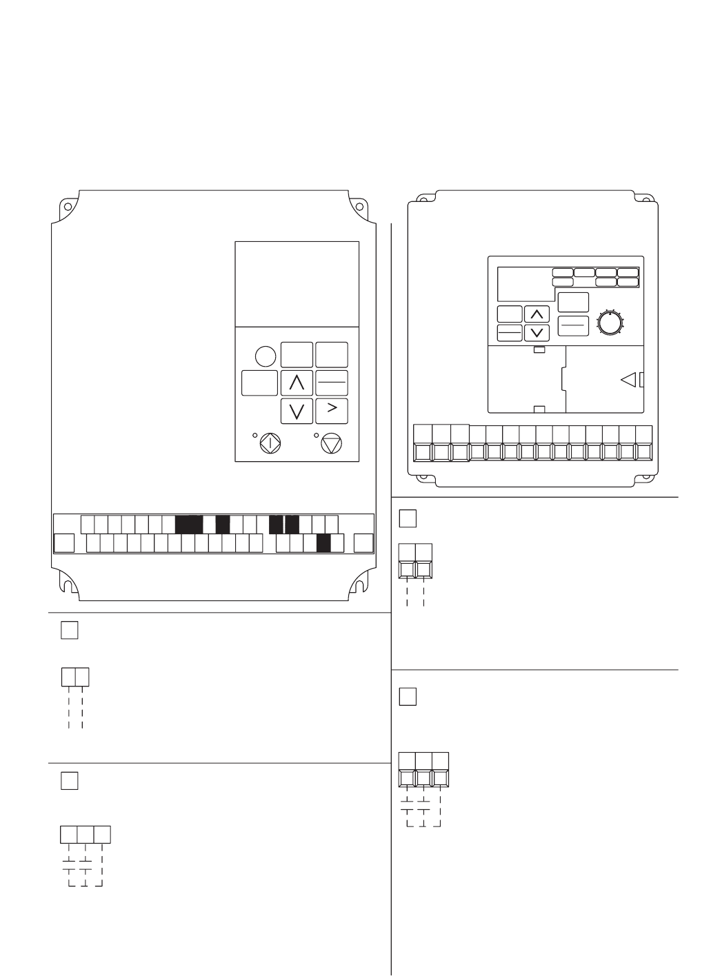
Variable Frequency Drives for Blowers
Optional factory installed, wired, and programmed variable frequency drives (VFD) may have been provided
for modulating or multi-speed control of the blowers. One VFD is provided for each blower (outdoor air and
exhaust). The VFDs provided are either Yaskawa model E7 or model GPD305. Refer to the tables on the
next page for factory settings and field wiring requirements. Refer to the unit control center for unit specific
wiring diagram (an example wiring diagram has been provided in this section for reference). When making
adjustments outside of the factory setpoints, refer to Yaskawa VFD instruction manual, which can be found
online at www.drives.com. For technical support, contact Yaskawa direct at 1-800-927-5292.
S3
SN SC SP
E(G) S1 S2
MCMBMAA1 A2 +V AC AC R+ R-
M4S6S5S4 FMS7 AC S-IGAM S+ M3 M2M1 E(G)
DATA
ENTER
STOP
HAND
RUN
OFF
RESET
MENU
MONITOR
AUTO
ESC
YASKAWA E7
YASKAWA
GPD 305/J7
S2
MA MB MC S1 FSS3 S4 SCS5 AMFR FC AC
STOP
RESET
DATA
ENTER
DSPL
RUN
MAXMIN
FOUT
F/R
FREF MNTR
PRGM
LO/RE
IOUT
OPTION 1 - 0-10 VDC CONTROL
FCFR
0-10 VDC CONTROL SIGNAL (BY OTHERS)
WIRED TO FR (+) AND FC (COMMON)
OPTION 2 - MULTI SPEED CONTROL
S5S4 SC
YASKAWA BLOWER VFD DETAIL WIRING
NEITHER S4 OR S5 CONTACT CLOSED
DRIVE SPEED = 60 Hz.
DRIVE SPEED = 40 Hz.
S4 TO SC CONTACT CLOSED (BY OTHERS)
S5 TO SC CONTACT CLOSED (BY OTHERS)
DRIVE SPEED = 30 Hz.
TO CHANGE THE FACTORY SET Hz CHANGE THE FOLLOWING PARAMETERS.
PARAMETER n01 CHANGE TO 1
PARAMETER n22 FOR NEW 40Hz SETTING
PARAMETER n21 FOR NEW 60Hz SETTING
PARAMETER n23 FOR NEW 30Hz SETTING
PARAMETER n01 CHANGE TO 0
FOR CONTINUOUS 60Hz OPERATION JUMPER TERMINALS FS AND FR.
0 VDC=30 Hz
10 VDC=60 Hz
USER TO PROVIDE CONTACTS
SEE VFD INSTALLATION MANUAL FOR MORE DETAIL
SEE VFD INSTALLATION MANUAL FOR MORE DETAIL
OPTION 1 - 0-10 VDC CONTROL
SEE VFD INSTALLATION MANUAL FOR MORE DETAIL
USER TO PROVIDE ISOLATION AS REQUIRED
FOR CONTINUOUS 60Hz OPERATION JUMPER TERMINALS A1 AND +V.
WIRED TO A1 (+) AND AC (COMMON)
0-10 VDC CONTROL SIGNAL (BY OTHERS)
10 VDC=60 Hz
0 VDC=30 Hz
A1 AC
SEE VFD INSTALLATION MANUAL FOR MORE DETAIL
PARAMETER A1-01 CHANGE TO 0
PARAMETER D1-03 FOR NEW 30Hz SETTING
PARAMETER D1-01 FOR NEW 60Hz SETTING
PARAMETER D1-02 FOR NEW 40Hz SETTING
PARAMETER A1-01 CHANGE TO 2
TO CHANGE THE FACTORY SET Hz CHANGE THE FOLLOWING PARAMETERS.
DRIVE SPEED = 30 Hz.
S6 TO SN CONTACT CLOSED (BY OTHERS)
S5 TO SN CONTACT CLOSED (BY OTHERS)
DRIVE SPEED = 40 Hz.
DRIVE SPEED = 60 Hz.
NEITHER S5 OR S6 CONTACT CLOSED
SNS5 S6
USER TO PROVIDE CONTACTS AND ISOLATION AS REQUIRED
OPTION 2 - MULTI SPEED CONTROL
AND ISOLATION AS REQUIRED
USER TO PROVIDE ISOLATION AS REQUIRED
FOR ONE 0-10 SIGNAL, WIRE TO DRIVES IN PARALLEL
FOR ONE 0-10 SIGNAL, WIRE TO DRIVES IN PARALLEL
Drawing No. 116329Part No. 465535
OPTIONAL ACCESSORIES
21
S1toSNcontactforOn/Off
A1(0-10VDC)referencedtoAC(Canuse+15VDCfrom+V)
Parameter Setting
A1-01 Access Level 2
C6-02 Carrier frequency 2
d2-02 Ref Lower Limit 50%
E2-01 Motor Rated FLA Motor FLA
H3-03 Terminal A1 Bias 50%
O2-03 User Defaults 1
A1-01 Access Level 0
S1 to SC contact for On/Off
FR(0-10VDC)referencedtoFC(Canuse+12VDCfromFS)
Parameter Setting
n01 Access Level 1
n31 Ref Lower Limit 50%
n32 Motor Rated FLA Motor FLA
n40 Multi-Function output (MA,MB,MC) 0
n42 Analog Freq. Reference Bias 50%
n46 Carrier Frequency 2
n01 Access Level 0
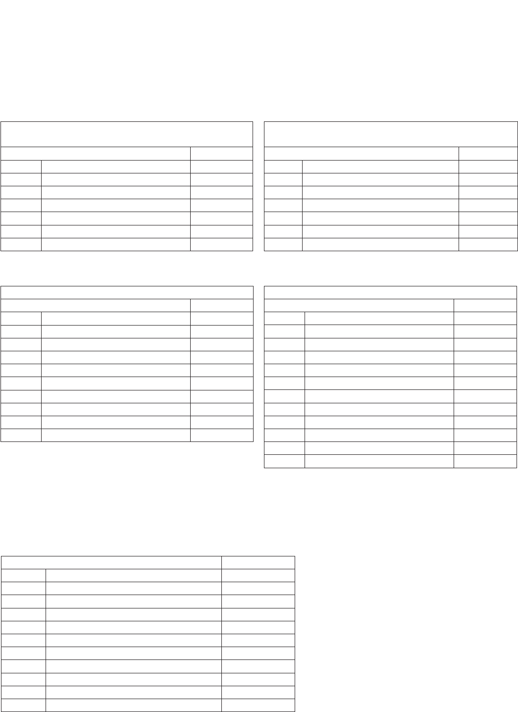
Factory Setpoints - MODULATING CONTROL (0-10 VDC) FOR FAN SPEED
Yaskawa E7 Drive Yaskawa GPD-305 Drive
OPTIONAL ACCESSORIES
Variable frequency drives (VFD) for the blowers are factory setup to receive a 0-10 VDC signal wired in the field
(refer to previous page for terminal locations). Most of the setpoints in the VFDs are factory defaults. There are
a few, though, that are changed at Greenheck and are shown in the tables below. To gain access to change
setpoints on the E7 drive, parameter A1-01 needs to be set at “2”. To gain access to change setpoints on the GPD-
305 drive, parameter n01 needs to be set at “1”. To prevent access on either drive, change the parameter to “0”.
Factory Setpoints - MULTI-SPEED CONTROL (1/3 OR 1/2 SPEED REDUCTION) FOR FAN SPEED
S1toSNcontactforOn/Off
Parameter Setting
A1-01 Access Level 2
b1-01 (Frequency) Reference Source 0
C6-02 Carrier frequency 2
d1-01 Frequency Reference 1 60
d1-02 Frequency Reference 2 40
d1-03 Frequency Reference 3 30
d1-04 Frequency Reference 4 60
E2-01 Motor Rated FLA Motor FLA
O2-03 User Defaults 1
A1-01 Access Level 0
Yaskawa E7 Drive
S1 to SC contact for On/Off
Parameter Setting
n01 Access Level 1
n03 Reference Selection 1
n21 Frequency Reference 1 60Hz
n22 Frequency Reference 2 40Hz
n23 Frequency Reference 3 30Hz
n24 Frequency Reference 4 60Hz
n32 Motor Rated FLA Motor FLA
n38* Multi-function Input Sel 4 (Term S4) 6
n39* Multi-function Input Sel 5 (Term S5) 7
n40 Multi-Function output (MA,MB,MC) 0
n46 Carrier Frequency 2
n01 Access Level 0
*Parameter n39 must be set to 7 before n38 can be set to 6 (the
drive does not allow these parameters to be the same number, n39
default is 6)
Yaskawa GPD-305 Drive
Variable Frequency Drives for
Energy Recovery Wheel
Factory installed VFD for the energy recovery wheel are programmed at the factory per the settings shown
below. Refer to the instruction manual that ships with the unit when making adjustments. A copy of the manual
can be found online at www.drives.com. For technical support, contact Yaskawa direct at 1-800-927-5292.
Parameter Setting
n01 Access Level 1
n30 Ref Upper Limit 100% or 66%*
n32 Motor Rated FLA Motor FLA
n33 Elect Thermal Overload 1
n36 Multi-Function input (terminal S2) 10
n40 Multi-Function output (MA,MB,MC) 4
n41 Analog Freq. Reference Gain 0
n42 Analog Freq. Reference Bias 99
n46 Carrier Frequency 2
n58 Frequency Detection Level 20
n01 Access Level 0
Yaskawa GPD-305 Drive
*36 inch wheel is 66% (40Hz). All other wheels are 100% (60Hz).
22
FACTORY SUPPLIED AND WIRED
G
MULTI-VOLTAGE PRIMARY
24 SECONDARY
TR1
C
FU5
TO UNIT
MAIN POWER
L3
L2
L1
DS1
SUPPLY DAMPER
D2
ENERGY WHEEL
R1
R
TR1
SO
SR
3
FR
FC
2-10V
-
+
1
TR
5
4
2
SR+
RETURN AIR SENSOR
MIXED AIR
SENSOR
T
T1
620 OHM RESISTOR OR
OUTDOOR AIR
SENSOR
SO+
4
S1
VFD-W
L3
34
SC
L2
L1
MC
T3
MA
T2
T1
PS1
NO CCOM NO
TS1
6
FROST CONTROL
A1
T1
A2
B1
16
15
T1
ENERGY WHEEL
S1
R1
LEGEND
CC COMPRESSOR CONTACTOR
CF CONDENSING FAN CONTACTOR
CH COMPRESSOR SUMP HEATER
D DAMPER
DB POWER DISTRIBUTION BLOCK
DL DAMPER LIMIT SWITCH
DS DISCONNECT SWITCH
EC ECONOMIZER CONTROLLER
FCS CONDENSOR FAN CYCLE SWITCH
FU FUSES
FU5 CONTROL TRANSFORMER FUSES (NOT ON CLASS II)
FZ1 FREEZE PROTECTION
HPS HIGH PRESSURE SWITCH (MANUAL RESET)
LPS LOW PRESSURE SWITCH
PS1 WHEEL FROST PRESSURE SWITCH
PS2 SUPPLY DIRTY FILTER PRESSURE SWITCH
PS3 EXHAUST DIRTY FILTER PRESSURE SWITCH
R1 ENERGY WHEEL RELAY/CONTACTOR
R2 OCCUPIED/UNOCCUPIED RELAY
R3 EXHAUST BLOWER VFD RELAY
R4 SUPPLY BLOWER VFD RELAY
R5 MODULATING WHEEL FROST CONTROL RELAY
R6 ECONOMIZER RELAY
R7 COMPRESSOR INTERLOCK RELAY
R8 EVAP RELAY (INDIRECT)
R9 EVAP RELAY (DIRECT)
R10 UNIT RELAY
S1 FAN SWITCH
S2 ROTATION SENSOR REED SWITCH
S3 ROTATION SENSOR REED SWITCH
S4 CALL FOR HEAT SWITCH
S5 BYPASS SWITCH
S6 CALL FOR COOL SWITCH (FIRST STAGE)
S7 CALL FOR COOL SWITCH (SECOND STAGE)
ST MOTOR STARTER
T1 FROST CONTROL TIMER
TYPICAL SETTINGS t1(OFF) = 5 MIN., t2(ON) = 30 MIN.
T2 ROTATION SENSOR TIMER
T3 ROTATION SENSOR TIMER
T4 ECONOMIZER WHEEL JOG TIMER
TYPICAL SETTINGS t1(OFF) = 3 HRS., t2(ON) = 10 SEC.
T5 EVAP DELAY OFF TIMER
T6 COMPRESSOR MINIMUM OFF TIMER (TYP. 3 MIN.)
T7 COMPRESSOR MINIMUM OFF TIMER (TYP. 3 MIN.)
TR TRANSFORMER
TS1 FROST CONTROL THERMOSTAT (JUMPER - HEAT )
CLOSES ON TEMP. DECREASE TYPICAL SETTING 5º F.
TS2 ECONOMIZER LOW LIMIT THERMOSTAT (JUMPER - HEAT )
OPENS ON TEMP. DECREASE TYP. SETTING 20º OFFSET OR 50ºF.
TS3 ECONOMIZER UPPER LIMIT THERMOSTAT (JUMPER - HEAT)
CLOSES ON TEMP. DECREASE TYP. SETTING 65º F. /2º DIFF.
TS4 ROOM OVERRIDE SENSOR
TS5 INLET AIR POST HEATER LOCKOUT THERMOSTAT (AFTER WHEEL)
CLOSES ON TEMP. DECREASE TYPICAL SETTING 65º F.
TS6 INLET AIR COMPRESSOR LOCKOUT THERMOSTAT (JUMPER-HEAT)
OPENS ON TEMP. DECREASE TYPICAL SETTING 60º F./2º DIFF.
A2 A1
o FIELD WIRED
FIELD CONTROL WIRING RESISTANCE SHOULD NOT EXCEED 0.75 OHM. IF
RESISTANCE EXCEEDS 0.75 OHM THEN CONSULT FA CTORY. USE 14 GAUGE
MINIMUM WIRE THICKNESS FOR CONTROL WIRING.
REPLACEMENT FUSES: MUST HAVE A MINIMUM I.R. RATING OF 5 KA
CAUTION:
UNIT SHALL BE GROUND IN ACCORDANCE WITH N.E.C.
POWER MUST BE OFF WHILE SERVICING.
USER INTERFACE CONNECTIONS:
*
*
*
*
*
*
o
*
*
*
*
*
*
*
*
D1 EXHAUST DAMPER
GROUND
FR FC
CR
CR
FROST CONTROL INDICATOR
6C
12 C
ROTATION INDICATOR
DIRTY FILTER INDICATOR SHOWN AS 24V POWER FROM UNIT.
SUPPLY DIRTY
FILTER SWITCH
EXHAUST DIRTY
FILTER SWITCH
DIRTY FILTER INDICATOR SHOWN AS 24V POWER FROM UNIT.
USER INTERFACE CONNECTIONS:USER INTERFACE CONNECTIONS:USER INTERFACE CONNECTIONS:
USER TO VERIFY THAT TR1 CAN HANDLE THE VA LOAD OF INDICATOR DEVICES.USER TO VERIFY THAT TR1 CAN HANDLE THE VA LOAD OF INDICATOR DEVICES.USER TO VERIFY THAT TR1 CAN HANDLE THE VA LOAD OF INDICATOR DEVICES.
USER TO VERIFY THAT TR1 CAN HANDLE THE VA LOAD OF INDICATOR DEVICES.
TO FR AND FC
ON VFD-W
SEE BELOW FOR
TERMINAL CONNECTIONS
C
NC NO
NC CNO
ECONOMIZER CONTROL
S6
Y1
MOTOR
MOTOR
EXHAUST FAN
SUPPLY FAN
SC
R4
R3
1
L1
L3
L2
S1
1
0-10 VDC
0-10 VDC
3
FR
VFD-S
3
FC
T1
T3
T2
SC
L1
L3
L2
S1 FR
VFD-E
FC
T1
T3
T2
VFD-E O.L.
MB MC
R3
27
EXHAUST FAN
VFD-S O.L.
MB MC
R4
27
SUPPLY FAN
6
R3
8
*
*
62
NC
S2 1
T2
C
12
MC
ROTATION SENSOR
MA ON VFD-W
TO MA AND MC
*
EC
THERMOSTAT(S) TS1,
24 VACTHERMOSTAT CONTROLLER(S)
OA-SENSOR
SENSOR COM
o
PS2
PS3
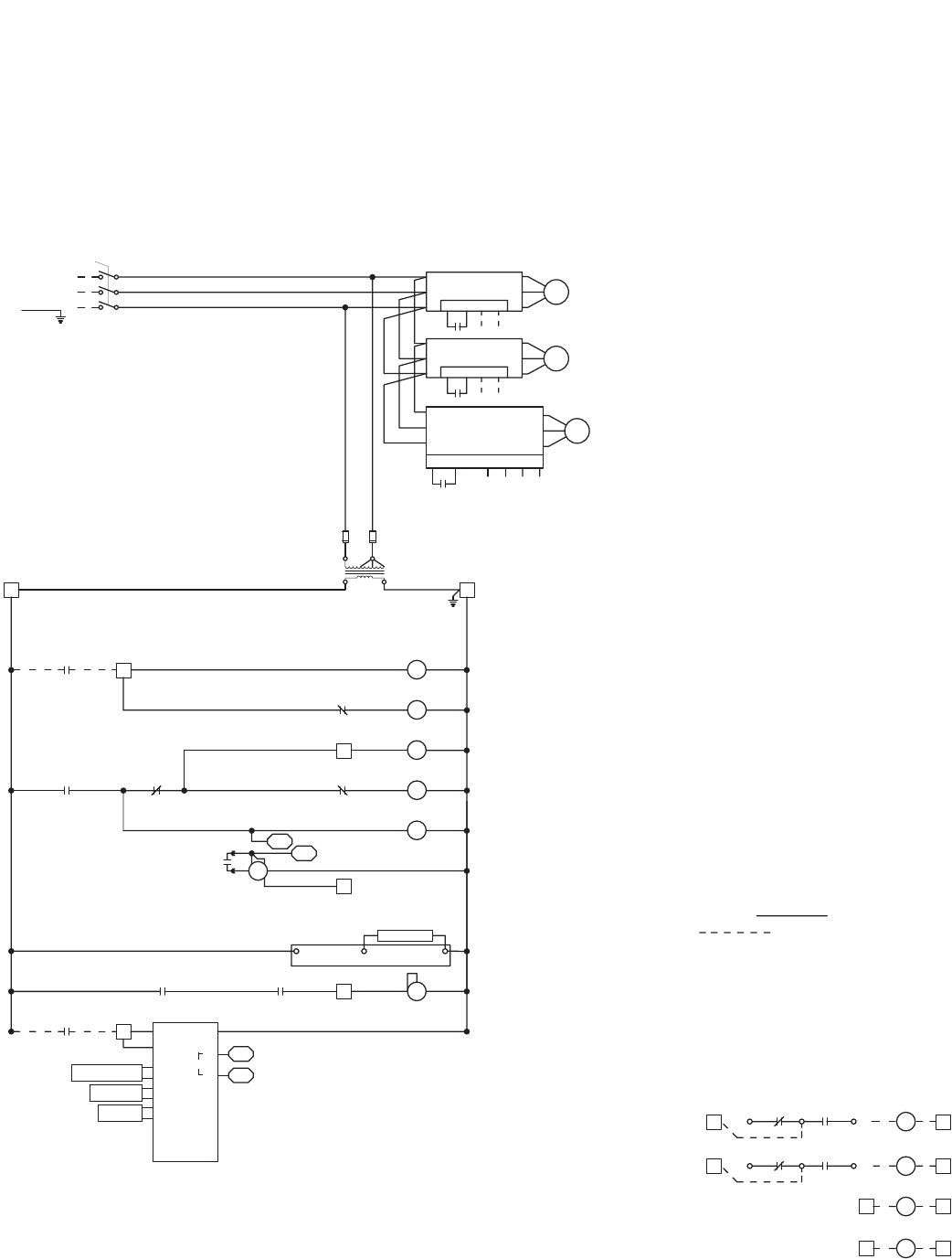
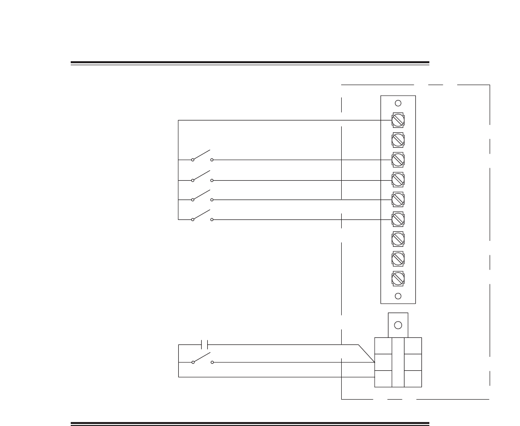
Following is an example of a typical wiring diagram located in the unit control center. This wiring diagram
includes a legend highlighting which accessories were provided with the unit. Factory wiring and field wiring
are also indicated. This particular example includes 1) variable frequency drives on the blowers requiring a
modulating input, 2) modulating energy recovery wheel with factory controls for economizer, 3) energy recovery
wheel rotation sensor, 4) outdoor air and exhaust air dirty filter switches, 5) motorized outdoor air and exhaust
air intake dampers, and 6) timed exhaust frost control. Many other factory installed and wired accessories are
available.
Wiring Diagram
OPTIONAL ACCESSORIES
23
Rotation Sensor
Dirty Filter Sensor
The rotation sensor monitors energy recovery wheel rotation. If the wheel should stop rotating, the sensor will
close a set of contacts in the unit control center. Field wiring of a light (or other alarm) between terminals R
& 12 in the unit control center will notify maintenance personnel when a failure has occurred (refer to Remote
Panel Wiring Schematics section for wiring details).
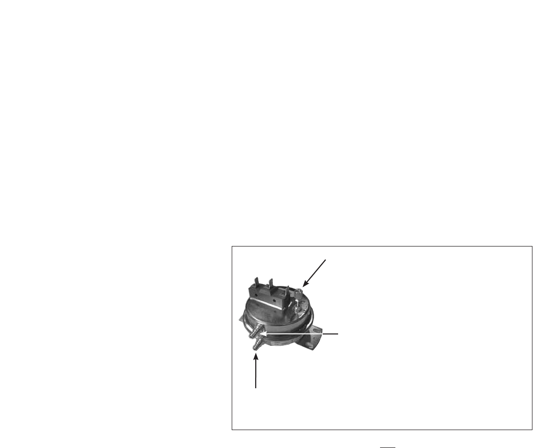
Dirty filter sensors monitor pressure drop across the outdoor air filters, exhaust air filters, or both. If the
pressure drop across the filters exceeds the set point, the sensor will close a set of contacts in the unit control
center. Field wiring of a light (or other alarm) to these contacts will notify maintenance personnel when filters
need to be replaced.
The switch has not been set at the factory due to external system losses that will affect the switch. This switch
will need minor field adjustments after the unit has been installed with all ductwork complete. The dirty filter
switch is mounted in the exhaust inlet compartment next to the unit control center or in unit control center.
To adjust the switch, the unit must be running
with all of the access doors in place, except for
the compartment where the switch is located
(exhaust inlet compartment). Model ERV units
require the opening around the control center
to be covered (with cardboard, plywood, etc.)
to set up dirty filter switch. The adjusting
screw is located on the top of the switch.
Open the filter compartment and place a
sheet of plastic or cardboard over 50% of the
filter media. Replace the filter compartment
door. Check to see if there is power at the alert
signal leads (refer to electrical diagram). If there
is no power, turn the adjustment screw on
the dirty filter gauge clockwise until you have
power. Open the filter compartment and remove
the obstructing material. Replace the door and check to make sure that you do not have power at the alert
signal leads. The unit is now ready for operation.
OPTIONAL ACCESSORIES
Setscrew (on front of switch) must be manually
adjusted after the system is in operation.
Positive pressure connection is toward the
“front or top” of the switch (senses air inlet
side of filters)
Negativepressureconnectionistowardthe“backorbottom”
of the switch (senses blower side of filters)
24
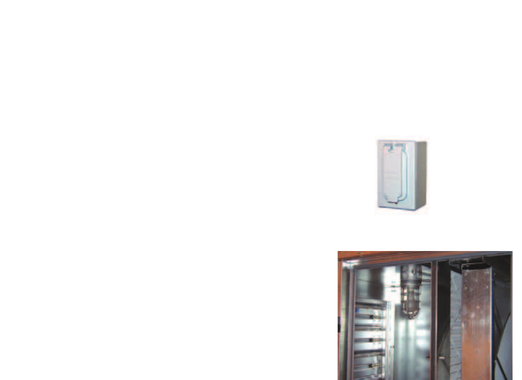
Vapor Tight Lights
Vapor tight lights provide light to each of the compartments
in the energy recovery unit. The lights are wired to a switch
mounted on the outside of the unit. The switch requires
a separate power source to allow for power to the lights
when the unit main disconnect is off for servicing.
OPTIONAL ACCESSORIES
Service Outlet
120 VAC GFCI service outlet ships loose for field
installation. Requires separate power source so power
is available when unit main disconnect is turned off for
servicing.
CO2 Sensor
This accessory is often used to provide a modulating control signal to a variable frequency drive to raise and
lower airflow in relationship to the CO2 levels in the space. This strategy is often referred to as Demand Control
Ventilation and provides further energy savings to the system. Follow instructions supplied with sensor for
installation and wiring details.
25
OPTIONAL ACCESSORIES
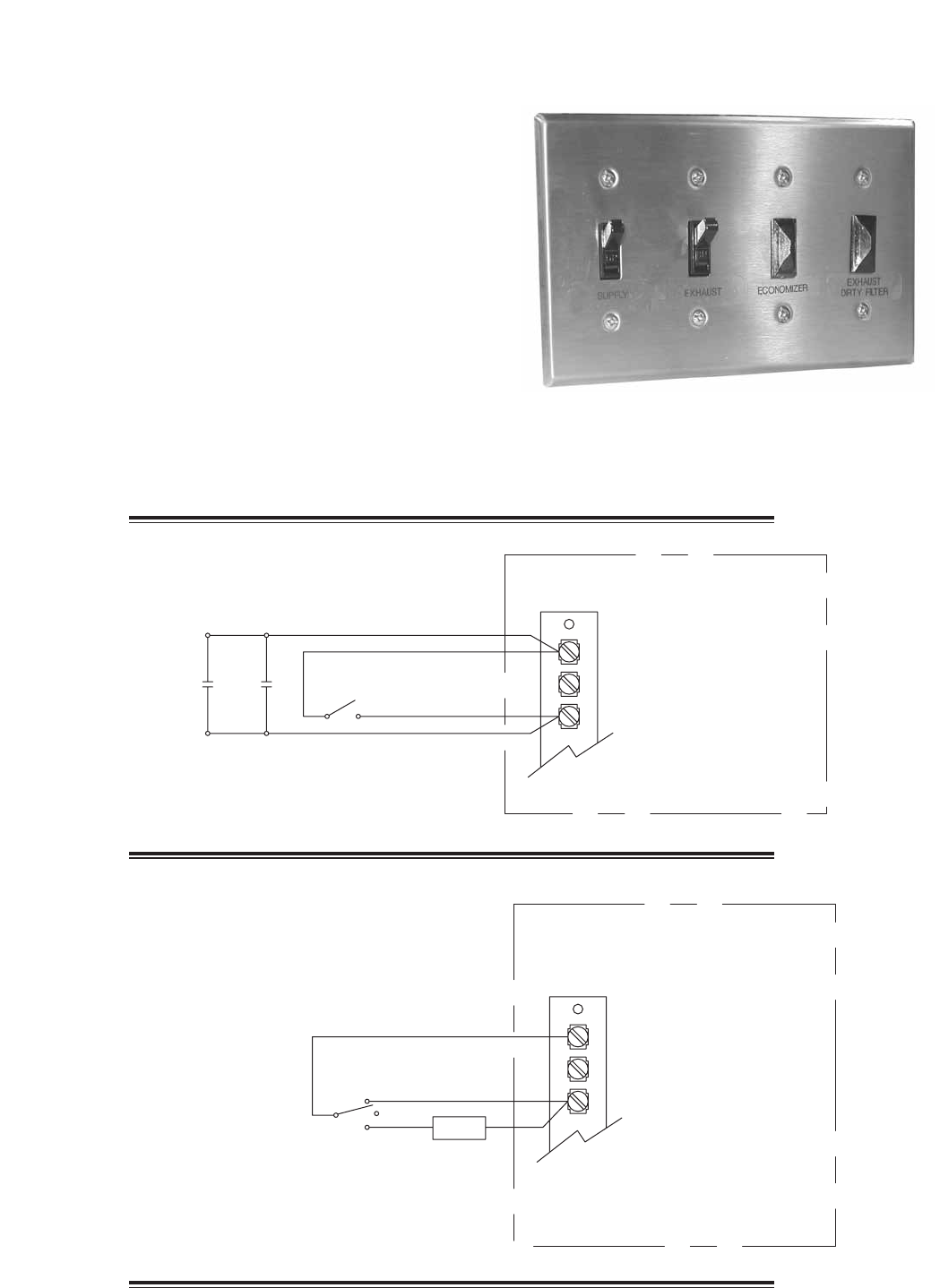
The remote panel is a series of junction boxes ganged
together and includes a stainless steel face plate. The
remote panel is available with a number of different alarm
lights and switches to control the unit. The remote panel
ships loose and requires mounting and wiring in the field.
Theremotepanelisavailablewiththefollowingoptions:
• Uniton/offswitch
• Uniton/offlight
• 7-daytimeclock
• Hand/off/autoswitch
• Timedelayoverride
• Exhaustairdirtyfilterlight
• Outdoorairdirtyfilterlight
• Economizerlight
• Frostcontrollight
• Wheelrotationsensorlight
Refer to Electrical Connections section for Field Control Wiring recommendations.
Remote Control Panel and Wiring Schematics
G
C
R
7-Day Timer or On/Off Switch
Timer
Override S1 - Unit On/Off
7-Day Timer
Terminal Block
in
Unit Control
Center
For 7-Day Timer, use blue and black wires.
Red wires should be capped off.
G
C
R
Hand/Off/Auto Switch
Terminal Block
in
Unit Control
Center
Hand/Off/Auto Switch allows the unit to
“Off” - off
“On” - Manual Operation
“Auto” - Unit is controlled by BMS, RTU, etc.
NOTE:RTUcontrollersarebyothers.
On
Off BMS
Auto
26
W1
12
7
6
Y2
Y1
G
C
R
NC C
NC C
NO
NO
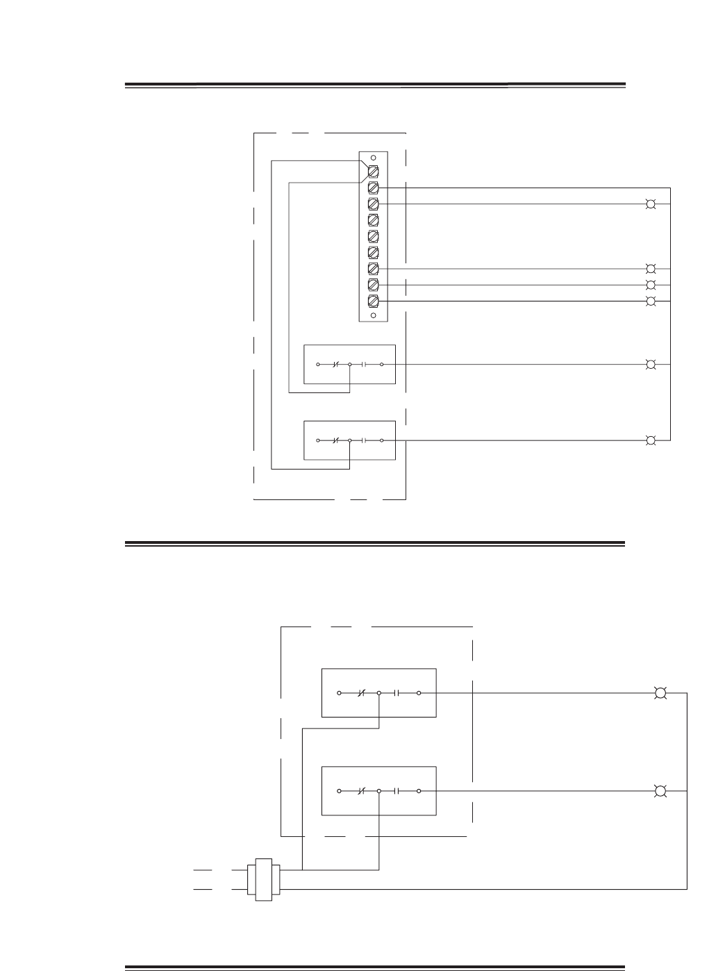
Indicator Lights
powered by the ER Unit
Unit On/Off
Frost Control
Economizer
Rotation Sensor
Supply Dirty Filter
Exhaust Dirty Filter
PS2
PS3
NC
NC
NO
C
NO
C
Dirty Filter Indicator
(Power by Others)
Supply Dirty Filter
Exhaust Dirty Filter
PS2
PS3
Hot
L1
Refer to Pressure Switch for voltage and load ratings.
OPTIONAL ACCESSORIES
Remote Panel Wiring Schematics
27
A3A3
W1
12
7
6
Y2
Y1
G
C
R
Heating/Cooling Switches and Night Setback
Switch/Timer
Unit On/Off
Heat
Econ/First Stage Cooling
Second Stage Cooling
NightSetbackSwitch
S1
S6
S7
S4
S5
Terminal Block in
Unit Control
Center
NightSetbackTimer
OPTIONAL ACCESSORIES
Remote Panel Wiring Schematics
28
OPTIONAL ACCESSORIES
RAI
RAF-P
RA
FILTER
OAAW
COOL
COIL
ACC
HEAT
COIL
OAF-A
OAD
SUPPLY
BLOWER
TO INSIDE
FROM INSIDE
EW-P
OAW-P
ENERGY WHEEL
EAWEF-A
OAI
OA
FILTER
OAF-P
TO
OUTSIDE
FROM
OUSTIDE
EXHAUST
BLOWER
Sensors Mounted by Factory
Factory mounted temperature, pressure, and current sensors are available in the locations indicated on the unit
diagram below. A list of available sensors is shown below. The specific sensors provided on a given unit are
labeled in the unit control center on the terminal strip. Sensors are wired to the terminal strip to make it easy for
the controls contractor to connect the Building Management System for monitoring purposes.
Pressure Sensors (analog or digital)
Drawing Labels Terminal Strip Labels
OAF-P OA/Supply Filter Pressure
OAW-P Outdoor Air Wheel Pressure
RAF-P RA/Exhaust Filter Pressure
EW-P Exhaust Wheel Pressure
Amp - Current Sensors (analog or digital)
Drawing Labels Terminal Strip Labels
OAF-P Supply Fan Amps
EF-A Exhaust Fan Amps
Temperature Sensors - 1K Ohm RTD
Drawing Labels Terminal Strip Labels
OAI OA/Supply Inlet Temp
OAAW OA After
ACC After Cooling Coil Temp
OAD Supply Discharge Temp
EAW Exhaust After Wheel Temp
RAI RA/Exhaust Inlet Temp

29
START-UP CHECKLIST FOR UNIT
UnitModelNumber ____________________________ (e.g. HRE-55)
UnitSerialNumber ____________________________ (e.g. 04C99999)
Energy Wheel Date Code ____________________________ (e.g. 0450)
Start-up date ____________________________ (MM/DD/YYYY)
Start-upPersonnelName ____________________________
Start-up Company ____________________________
PhoneNumber ____________________________
Pre-Start Up Checklist - check boxes as items are completed
o Disconnect and lock-out all power switches
o Remove any foreign objects that are located in the energy recovery unit.
o Check all fasteners, set-screws, and locking collars on the fans, bearings, drives, motor bases and
accessories for tightness.
o Rotate the fan wheels and energy recovery wheels by hand and ensure no parts are rubbing. If rubbing
occurs, refer to Start-Up section for more information.
o Check the fan belt drives for proper alignment and tension (refer to Start-Up section for more
information).
o Filters can load up with dirt during building construction. Replace any dirty pleated filters and clean the
aluminum mesh filters in the intake hood (refer to Routine Maintenance section).
o Verify that non-motorized dampers open and close properly.
o Check the tightness of all factory wiring connections.
o Verify control wire gauge (refer to the Electrical Connections section).
o Verify diameter seal settings on the energy recovery wheel (refer to Start-Up section for more
information.
o Verify proper drain trap installation (refer to Drain Trap section).
o For plenum or BI fans, check the radial gap and overlap. Adjust if necessary.
Every installation requires a comprehensive start-up to ensure proper operation of the unit. As part of
that process, the following checklist must be completed and information recorded. Starting up the unit in
accordance with this checklist will not only ensure proper operation, but will also provide valuable information
to personnel performing future maintenance. Should an issue arise which requires factory assistance, this
completed document will allow unit experts to provide quicker resolve. Qualified personnel should perform
start-up to ensure safe and proper practices are followed.
SAFETY CAUTION!
Use caution when removing access panels or other
unit components, especially while standing on a
ladder or other potentially unsteady base. Access
panels and unit components can be heavy and
serious injury may occur.
SAFETY CAUTION!
Do not operate energy recovery ventilator without
the filters and birdscreens installed. They prevent the
entry of foreign objects such as leaves, birds, etc.
SAFETY DANGER!
Electric shock hazard. Can cause injury or death.
Before attempting to perform any service or
maintenance, turn the electrical power to unit to OFF
at disconnect switch(es). Unit may have multiple
power supplies.
CAUTION!
Do not run unit during construction phase. Damage
to internal components may result and void warranty.

30
Line Voltage - check at unit disconnect
L1-L2 ________ Volts L2-L3 ________ Volts L1-L3 _______ Volts
MotorAmpDraw:
Supply Motor Amps L1 ________ Amps L2 ________ Amps L3 ________ Amps
Exhaust Motor Amps L1 ________ Amps L2 ________ Amps L3 ________ Amps
FanRPM: SupplyFanRPM _____________
Exhaust Fan RPM _____________
Correctfanrotationdirection: SupplyFan Yes/No
ExhaustFan Yes/No
Start-Up Checklist
The unit will be in operational mode during start-up. Use necessary precautions to avoid injury. All data must
be collected while the unit is running. In order to measure volts & amps, the control center door must be open,
and the unit energized using a crescent wrench to turn the disconnect handle.
Special Tools Required
Voltage Meter (with wire probes)
Amperage Meter
Incline manometer or equivalent
Tachometer
Thermometer
START-UP CHECKLIST FOR UNIT
START-UP CHECKLIST FOR EVAPORATIVE COOLER
Evaporative coolers are an integral part of the unit and must be set up properly. Doing so will ensure correct
operation and avoid water or leakage problems. HRE units will have one or two evaporative coolers. The
following checklist must be completed for each evaporative cooler. Qualified personnel should perform
installation and be present for start-up to ensure safe and proper practices are followed. Please refer to the
Evaporative Cooling Modules section for detailed information on start-up items below.
Indirect Evap Direct Evap
Connect overflow line (run bleed line into overflow) o o
Connect drain line o o
Install trap o o
Connect water supply line o o
For units with Auto Drain & Fill with Freeze Protection
Install, wire, and provide power to components o o
Confirm temperature and timer settings o o
Pump filter clean and installed properly o o
Saturate media per IOM o o
Adjust bleed-off rate per IOM o o
Check for water carryover o o
Connect ‘Call for Cooling’ signal o o
Remove jumper wire o o

31
Refer to the respective sections in this Installation, Operation and Maintenance Manual for detailed information.
Refer to wiring diagram in unit control center to determine what electrical accessories were provided.
Provided with Unit? Frost Control Application / Operation section: Setting Factory Default
Yes No Frost Control Setpoint 5ºF
Differential 2ºF
Timer Refer to IOM
Yes No Frost Control Modulating Refer to IOM
Economizer Application / Operation section:
Yes No Economizer (temperature)
Setpoint 65ºF
Offset 20ºF
Differential 2ºF
Yes No Economizer (enthalpy)
Setpoint B
Yes No Economizer (modulating) Refer to IOM
Optional Accessories section: Operational
Yes No Wheel Rotation Sensor YesNoN/A
Yes No OA Dirty Filter Sensor YesNoN/A
Yes No EA Dirty Filter Sensor YesNoN/A
Yes No CO2 Sensor YesNoN/A
Yes No Service Outlet YesNoN/A
Yes No Vapor Tight Lights YesNoN/A
Yes No Remote Control Panel YesNoN/A
Variable Frequency Drives section: Operational
Yes No Blower VFDs YesNoN/A
Yes No Wheel VFD YesNoN/A
Damper section: Operational
Yes No Outdoor Air Damper YesNoN/A
Yes No Exhaust Air Damper YesNoN/A
Yes No NightSetbackDamper YesNoN/A
Yes No Indirect Gas Furnace (refer to the PVF IOM, Part #461006 for start-up information)
Standard Indirect Evaporative Cooler Section (refer to Evap Start-Up checklist on following page)
Yes No Direct Evaporative Cooler Section (refer to Evap Start-Up checklist on following page)
OPTIONAL ACCESSORIES CHECKLIST
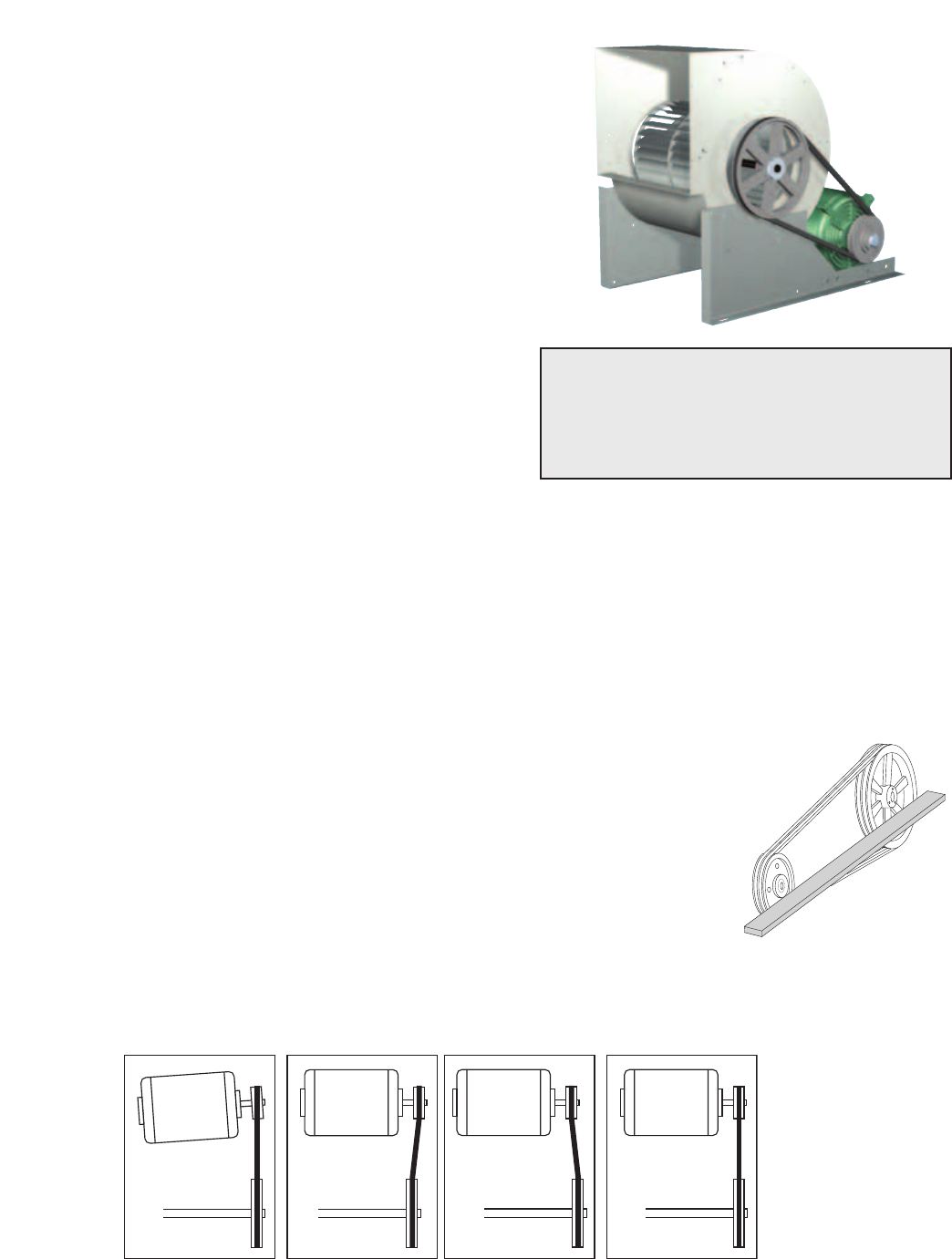
32
Fans (Forward Curved Type)
The HRE Models contain a forward curved supply fan and
a forward curved exhaust fan. These forward curved fans
should be checked for free rotation. If any binding occurs,
check for concealed damage and foreign objects in the fan
housing. Be sure to check the belt drives per the start-up
recommendations in the following section.
Fan Performance Modifications
Due to job specification revisions, it may be necessary to
adjust or change the sheave or pulley to obtain the desired
airflow at the time of installation. Start-up technician must
check blower amperage to ensure that the amperage listed
on the motor nameplate is not exceeded. Amperage to be
tested with access doors closed and ductwork installed.
SAFETY CAUTION!
When operating conditions of the fan are to be
changed (speed, pressure, temperature, etc.),
consult Greenheck to determine if the unit can
operate safely at the new conditions.
UNIT START-UP
Refer to Parts List section for component locations.
Belt Span
Deflection = Belt Span
64
WRONG WRONG
WRONG CORRECT
Belt Span
Deflection = Belt Span
64
WRONG WRONG
WRONG CORRECT
Belt Drive Installation
1. Remove the protective coating from the end of the fan shaft and
assure that it is free of nicks and burrs.
2. Check fan and motor shafts for parallel and angular alignment.
3. Slide sheaves on shafts - do not drive sheaves on as this may result
in bearing damage.
4. Align fan and motor sheaves with a straight-edge or string and
tighten.
5. Place belts over sheaves. Do not pry or force belts, as this could
result in damage to the cords in the belts.
6. With the fan off, adjust the belt tension by moving the motor base. (See
belt tensioning procedures in the Routine Maintenance section of this
manual). When in operation, the tight side of the belts should be in a
straight line from sheave to sheave with a slight bow on the slack side.
FAN MOTOR FAN
MOTOR
Proper alignment of motor and drive shaft.
Fan Belt Drives
The fan belt drive components, when supplied by Greenheck, have been carefully selected for the unit’s
specificoperatingcondition.Caution:utilizingdifferentcomponentsthanthosesuppliedcouldresultinunsafe
operatingconditionswhichmaycausepersonalinjuryorfailureofthefollowingcomponents:1)FanShaft,2)
Fan Wheel, 3) Bearings, 4) Belt, 5) Motor. Tighten all fasteners and set screws securely and realign drive pulleys
after adjustment. Check pulleys and belts for proper alignment to avoid unnecessary belt wear, noise, vibration
and power loss. Motor and drive shafts must be parallel and pulleys in line (see below).
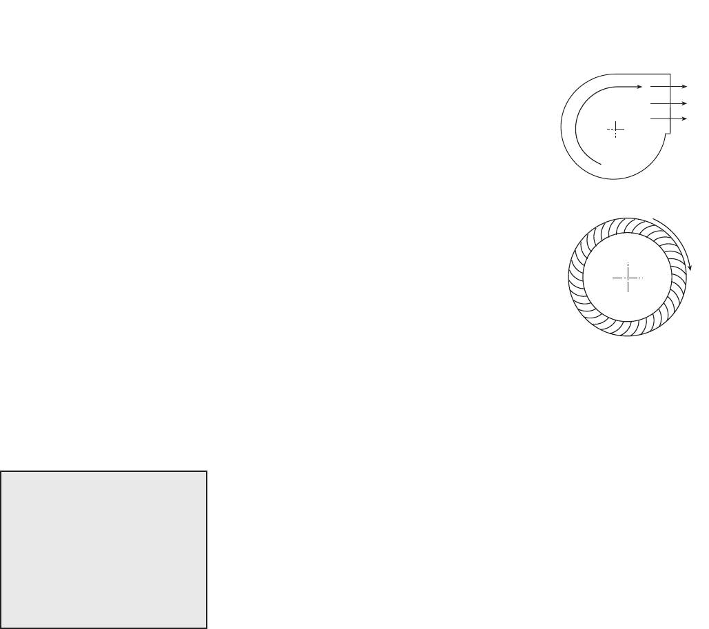
33
Vibration
Excessive vibration may be experienced during initial start-up. Left unchecked, excessive vibration can cause
a multitude of problems, including structural and/or component failure. The most common sources of vibration
are listed below.
Many of these conditions can be discovered by careful observation. Refer
to the Troubleshooting section of this manual for corrective actions. If
observation cannot locate the source of vibration, a qualified technician using
vibration analysis equipment should be consulted. If the problem is wheel
unbalance, in-place balancing can be done.
Generally, fan vibration and noise is transmitted to other parts of the building
by the ductwork. To eliminate this undesirable effect, the use of heavy canvas
connectors is recommended.
1. Wheel Unbalance
2. Drive Pulley Misalignment
3. Incorrect Belt Tension
4. Bearing Misalignment
5. Mechanical Looseness
6. Faulty Belts
7. Drive Component Unbalance
8. Poor Inlet/Outlet Conditions
9. Foundation Stiffness
UNIT START-UP
R
o
t
a
t
i
o
n
R
o
t
a
t
i
o
n
R
o
ta
t
io
n
R
o
ta
t
io
n
Backward Inclined
Forward Curved
Airflow
Airflow
Rotation Direction
R
o
t
a
t
i
o
n
R
o
t
a
t
i
o
n
R
o
ta
t
io
n
R
o
ta
t
io
n
Backward Inclined
Forward Curved
Airflow
Airflow
Direction of Fan Wheel Rotation
Blower access is labeled on unit. Check for proper wheel rotation by momentarily
energizing the fan. Rotation is determined by viewing the wheel from the drive
side and should match the rotation decal affixed to the fan housing (see Rotation
Direction figures). If the wheel is rotating the wrong way, direction can be reversed
by interchanging any two of the three electrical leads. Check for unusual noise,
vibration, or overheating of bearings. Refer to the Troubleshooting section of this
manual if a problem develops.
Fan RPM
Supply fan and exhaust fan will have an adjustable motor pulley (on 15 HP and
below) preset at the factory to the customer specified RPM. Fan speed can be
increased or decreased by adjusting the pitch diameter of the motor pulley. Multi-
groove variable pitch pulleys must be adjusted an equal number of turns open or
closed. Any increase in fan speed represents a substantial increase in load on the
motor. Always check the motor amperage reading and compare it to the amperage
rating shown on the motor nameplate when changing fan RPM. All access doors
must be installed except the control center door. Do not operate units with access
doors open or without proper ductwork in place as the fan motors will overload.
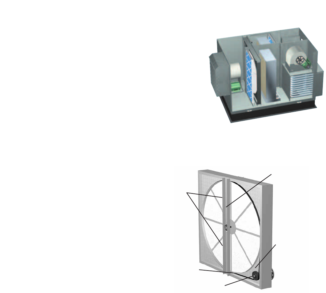
34
UNIT START-UP
Energy Recovery Wheel
The HRE models contain a sensible energy recovery wheel. The
wheels are inspected for proper mechanical operation at the
factory. However, during shipping and handling, shifting can occur
that may affect wheel operation. The wheel is accessible through
the access door marked “Energy Wheel Cassette Access”. For
theHRE-20ANDHRE-45models,thewheelcassetteslidesout.
DuetothesizeandweightoftheHRE-55ANDHRE-90wheels,
they remain stationary and all maintenance is performed in place.
There is room inside the unit to perform energy recovery wheel
servicing.
Turn the energy recovery wheels by hand to verify free operation.
The wheel should rotate smoothly and should not wobble.
Drive Belt
Inspect the drive belt. Make sure the belt rides smoothly through the pulley and over the wheel rim.
Air Seals
Air seals are located around the perimeter of the
wheel and across the face of the wheel (both sides
of wheel). Check that these seals are secure and in
good condition.
Check that the air seals located around the outside
of the wheel and across the center (both sides of
wheel) are secure and in good condition. Air seal
clearance is determined by placing a sheet of
paper, to act as a feeler gauge, against the wheel
face. To access seals, enter unit for HRE-55 &
HRE-90, or pull out the cassette for HRE-20 & HRE-
45, following the instructions in Energy Recovery
Wheel Maintenance section. To adjust the air seals,
loosen all eight seal retaining screws. These screws
are located on the bearing support that spans the
length of the cassette through the wheel center.
Tighten the screws so the air seals tug slightly on the sheet of paper.
Replace cassette into unit, plug in wheel drive, replace access door and apply power. Observe by opening door
slightly (remove filters if necessary to view wheel) that the wheel rotates freely at about 35 RPM.
Drive Belt
Drive Pulley
Adjustable
Air Seals
Label showing
cassette serial #
and date code
Bearing Support
Inside layout of HRE unit

35
Once the unit has been put into operation, a routine maintenance program should be set up to preserve
reliabilityandperformance.Itemstobeincludedinthisprogramare:
SAFETY CAUTION!
Use caution when removing access panels or other
unit components, especially while standing on a
ladder or other potentially unsteady base. Access
panels and unit components can be heavy and
serious injury may occur.
SAFETY DANGER!
Electric shock hazard. Can cause injury or death.
Before attempting to perform any service or
maintenance, turn the electrical power to unit to OFF
at disconnect switch(es). Unit may have multiple
power supplies.
ROUTINE MAINTENANCE
DATE DATE DATE DATE
______ ______ ______ _____
Lubrication
Apply lubrication where required oooo
Dampers
Check for unobstructed operation ooo o
Fan Belts
Check for wear, tension, alignment ooo o
Motors
Check for cleanliness ooo o
Blower Wheel & Fasteners
Check for cleanliness ooo o
Check all fasteners for tightness ooo o
Check for fatigue, corrosion, wear ooo o
Bearings
Check for cleanliness oooo
Check set screws for tightness oooo
Lubricate as required ooo o
External Filter
Check for cleanliness - clean if required ooo o
Internal Filter
Check for cleanliness - replace if required ooo o
Door Seal
Check if intact and pliable ooo o
Coil Maintenance
Check for cleanliness (coil and drain pan) ooo o
Winterizing Coils
Drain - Fill with antifreeze - Drain ooo o
Energy Recovery Wheel
Check for cleanliness - clean if required ooo o
Check belt for wear ooo o
Check pulley, bearings, and motor ooo o
Evap Cooler Section
Refer to Evaporative Cooler Maintenance section ooo o
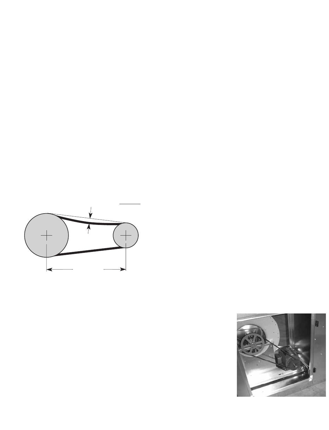
36
ROUTINE MAINTENANCE
Proper fan belt settings
Belt Span
Deflection = Belt Span
64
The proper belt setting is the lowest tension
at which the belts will not slip under peak load
operation. For initial tensioning, set the belt
deflection at 1/64-inch for each inch of belt span
(measured half-way between sheave centers).
For example, if the belt span is 64 inches, the
belt deflection should be 1 inch (using moderate
thumb pressure at mid-point of the drive). Check
belt tension two times during the first 24 hours of
operation and periodically thereafter.
Fan Belts
Belts must be checked on a regular basis for wear, tension, alignment, and dirt accumulation. Premature
or frequent belt failures can be caused by improper belt tension (either too loose or too tight) or misaligned
sheaves. Abnormally high belt tension or drive misalignment will cause excessive bearing loads and may result
in failure of the fan and/or motor bearings. Conversely, loose belts will cause squealing on start-up, excessive
belt flutter, slippage, and overheated sheaves. Both loose and tight belts can cause fan vibration.
When replacing belts on multiple groove drives, all belts should be changed to provide uniform drive loading.
Do not pry belts on or off the sheave. Loosen belt tension until belts can be removed by simply lifting the
belts off the sheaves. After replacing belts, insure that slack in each belt is on the same side of the drive. Belt
dressing should never be used.
Do not install new belts on worn sheaves. If the sheaves have grooves worn in them, they must be replaced
before new belts are installed.
Lubrication
Check all moving components for proper lubrication. Apply lubrication where required. Any components
showing excessive wear should be replaced to maintain the integrity of the unit and ensure proper operation.
Dampers
Check all dampers to ensure they open and close properly and without binding. Backdraft dampers can be
checked by hand to determine if blades open and close freely. Apply power to motorized dampers to ensure
the actuator opens and closes the damper as designed.
Fan Motors
Motor maintenance is generally limited to cleaning and lubrication. Cleaning
should be limited to exterior surfaces only. Removing dust and grease buildup
onthemotorhousingassistspropermotorcooling.Neverwash-downmotor
with high pressure spray. Greasing of motors is only intended when fittings are
provided. Many fractional motors are permanently lubricated for life and require
no further lubrication.
Fan Wheel & Fasteners
Wheels require very little attention when moving clean air. Occasionally oil and
dust may accumulate on the wheel causing imbalance. When this occurs the
wheel and housing should be cleaned to assure smooth and safe operation.
Inspect fan impeller and housing for fatigue, corrosion or wear.
Routinely check all fasteners, set screws and locking collars on the fan, bearings, drive, motor base and
accessories for tightness. A proper maintenance program will help preserve the performance and reliability
designed into the fan.
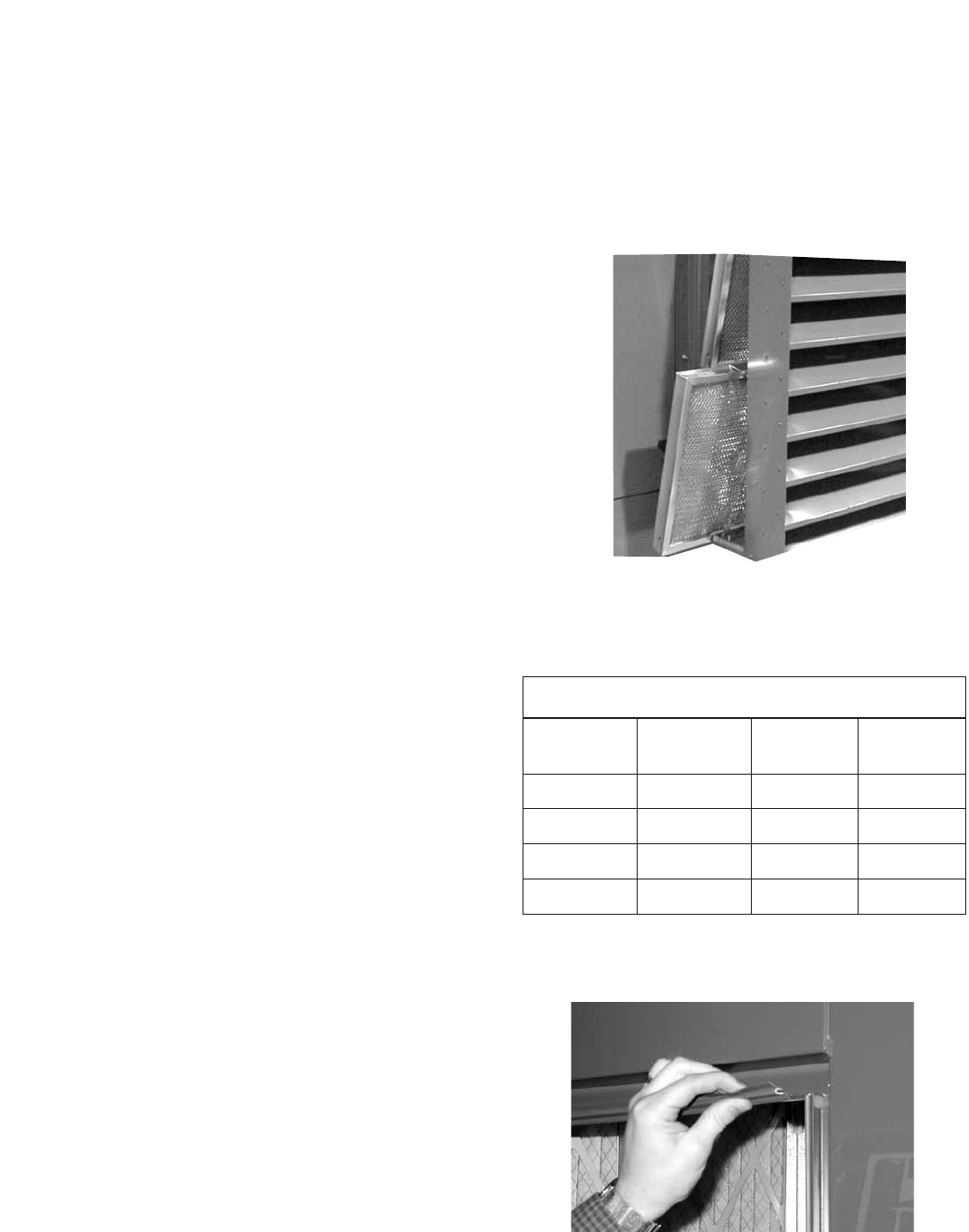
37
External Filter Maintenance
Aluminum mesh, 2-inch deep filters are located in the
supply weatherhood (if the weatherhood option was
purchased). Filters should be checked and cleaned on
a regular basis for best efficiency. The frequency of
cleaning depends upon the cleanliness of the incoming
air. These filters should be cleaned prior to start-up.
To access these filters, remove bottom bolt in the access
door on the side of the weatherhood. Slide the access
door up and then pull bottom out to remove door. Then,
slide the filters out (see figure at right).
Clean filters by rinsing with a mild detergent in warm
water.
Internal Filter Maintenance
The HRE units will typically be provided with 2-inch,
pleated filters in the outdoor air and exhaust airstreams.
These filters should be checked per a routine
maintenance schedule and replaced as necessary to
ensure proper airflow through the unit. See table at
right for pleated filter size and quantity for each unit.
Replacement filters shall be of same performance and
quality as factory installed filters. Filter type must be
pleated design with integral metal grid. Two acceptable
filter replacements are Aerostar Series 400 or Farr 30/30®.
Outdoor Air Filters: Access to the outdoor air filters
is through the door labeled as “Filter Access” on the
outdoor air side of the unit.
Exhaust Air Filters: Access to the exhaust air filters
is through the door labeled as “Filter Access” on the
exhaust air side of the unit.
Refer to Access Door Descriptions section for additional
information on filter locations.
Door Seal Maintenance
Slip-on type vinyl seal is installed on the perimeter of the
door openings. Inspect at least annually to ensure that
seal is still pliable and intact.
Outdoor air intake hood
mesh filter access
ROUTINE MAINTENANCE
Filter Size and Quantities
Model Internal
Filter Size
Quantity
Supply
Quantity
Exhaust
HRE-20 20 in. x 20 in. 2 2
HRE-45 20 in. x 25 in. 3 3
HRE-55 16 in. x 25 in. 6 6
HRE-90 20 in. x 20 in. 8 8
Bearings
Mostbearingsarepermanentlylubricatedandrequirenotfurtherlubricationundernormaluse.Normaluse
being considered -20ºF to 120ºF and in a relatively clean environment. Some bearings are re-lubricatable and
will need to be regreased depending on fan use. Check your bearings for grease zert to find out what type of
bearing you have. If your fan is not being operated under normal use, bearings should be checked monthly for
lubrication.
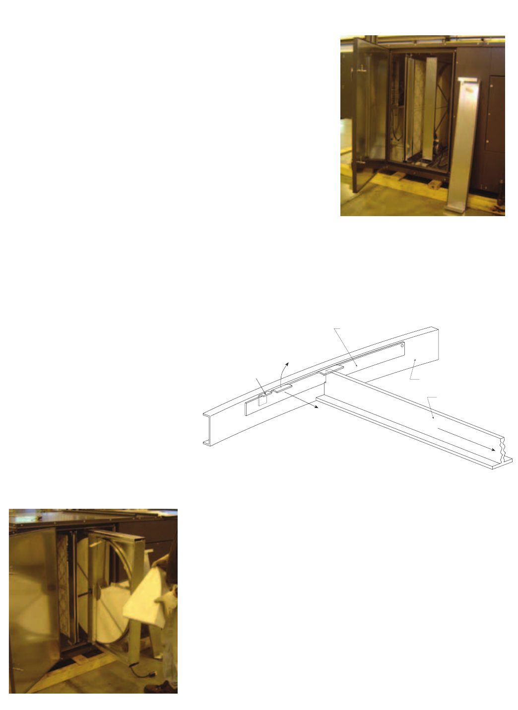
38
Access to wheel through
outdoor air filter door
The HRE units have one energy recovery wheel. Open the outdoor
air filter door to access the wheel. For the HRE-20 and HRE-45
models, the wheel cassette slides out. Due to the size and weight
of the HRE-55 and HRE-90 wheels, they remain stationary and all
maintenance is performed in place. There is room inside the unit to
perform energy recovery wheel servicing. Filters must be removed to
access stationary wheels.
**WARNING: Disconnect power to the unit before performing
any type of service.
ACCESSING ENERGY RECOVERY WHEEL
Energy Recovery Wheel Maintenance
Annual inspection of the energy recovery wheel is recommended. Units
ventilating smoking lounges and other non-clean air spaces should
have energy recovery wheel inspections more often based upon need.
Inspections for smoke ventilation applications are recommended
bimonthly to quarterly until a regular schedule can be established.
ROUTINE MAINTENANCE
IMPORTANT! PLACE RETAINERS BACK IN THE
ORIGINAL POSITION BEFORE
ROTATING THE ENERGY RECOVERY WHEEL.
OTHERWISE DAMAGE TO RETAINER WILL
OCCUR.
Bracket Segment Retainer
Lift Away
From Segment
Catch-
Segment Retainer
Push Toward Center
Center of Wheel
Spoke
Inside of Wheel Rim
Models HRE-20, 45, 55, & 90
Steel retainers are located on the
inside of the wheel rim (see diagram
at right). Push the retainer toward
center of wheel, then lift up and
away to release segments (see
below).
REMOVING THE ENERGY RECOVERY WHEEL SEGMENTS
Wheel segment removed
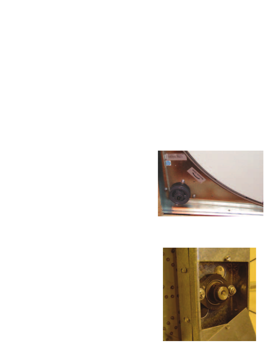
39
CLEANING THE ENERGY RECOVERY WHEEL
If the wheel appears excessively dirty, it should be cleaned to ensure maximum operating efficiency. Only
excessive buildup of foreign material needs to be removed. DISCOLORATION AND STAINING OF ENERGY
RECOVERY WHEEL DOES NOT AFFECT ITS PERFORMANCE.
Thoroughly spray wheel matrix with household cleaner such as Fantastic® or equivalent. Gently rinse with
warm water and using a soft brush remove any heavier accumulation. A detergent/water solution can also be
used. Avoid aggressive organic solvents, such as acetone. The energy recovery wheel segments can be soaked
in the above solution overnight for stubborn dirt or accumulation.
After cleaning is complete, shake the excess water from the wheel or segments. Dry wheel or segments
before placing them back into the cassette. Place wheel or segments back into cassette by reversing removal
procedures.
** DO NOT CLEAN ENERGY RECOVERY WHEEL SEGMENTS WITH WATER IN EXCESS OF 140ºF
** DO NOT DRY ENERGY RECOVERY WHEEL SEGMENTS IN AIR IN EXCESS OF 140ºF.
** THE USE OF A PRESSURE WASHER TO CLEAN SEGMENTS IS NOT RECOMMENDED. DAMAGE COULD
RESULT.
Energy Recovery Wheel Belt
Energy Recovery Wheel Bearings
Inspect belts each time filters are replaced. Belts that
look chewed up or are leaving belt dust near the motor
pulley may indicate a problem with the wheel. Be sure to
inspect wheel for smooth and unrestricted rotation. If a
belt requires replacement, contact the local Greenheck
representative. Instructions for replacement will ship with
the new belt.
Wheel Belt & Pulley
In the unlikely event that a wheel bearing fails, access is
available through the outdoor air filter door and through
a removable plate in the divider in the unit (accessed
through the exhaust air filter door). Contact the local
Greenheck representative for detailed instructions on how
to replace the bearing.
ROUTINE MAINTENANCE
Wheel Bearing
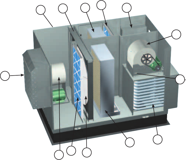
40
PARTS LIST
1
2
3
4
8
5
67
7
9
Model HRE
(shown with indirect evaporative
cooler, optional direct evaporative
cooler, and indirect gas heater)
10
1. Supply blower
- Forward curved fan
- Adjustable motor mount for belt tensioning
- Adjustable sheaves for speed control
2. Vibrations isolators (quantity 4 per blower)
-Neoprene
3. Energy recovery wheel cassette
4. Removable energy recovery wheel segments
5. Optional supply weatherhood with 2 in. aluminum
mesh filter
6. Optional exhaust weatherhood with birdscreen
7. Optional supply and exhaust air filter racks for
2 in. pleated, 30% efficient filters
8. Electrical control box (standard features)
- Single point power
- Disconnect interlocked with access door
- Motor starters for the supply blower, exhaust
blower and energy wheel motors
- 24 Vac, control circuit with terminal strip
9. Supply air tempering options
- Electric heat (requires separate power)
- Hot water heat
- Indirect gas heat
10. Exhaust blower
- Forward curved fan
- Adjustable motor mount for belt tensioning
- Adjustable sheaves for speed control
11. Indirect evaporative cooler
12. Direct evaporative cooler
11
12

41
The HRE units are pre-wired such that when a call for outside air is made (via field supplied 24 VAC control
signal wired to unit control center), the supply fan, exhaust fan and energy wheel are energized and the
motorized dampers open. The HRE units can be supplied with or without heating and cooling coils. For units
with coils, controls can be supplied by Greenheck or by the controls contractor. If supplied by the controls
contractor, they would provide, mount, and wire any temperature controllers and temperature or relative
humidity sensors required for the unit to discharge air at the desired conditions.
Basic Unit
A sensible wheel preconditions the outdoor air (temperature is decreased) by the transfer of energy from the
cool exhaust air coming out of the indirect evaporative cooler.
Units supplied with a direct evaporative cooling coil can further cool the air coming off the wheel to levels near
55ºF.
EconomizerOperation:SeeEconomizerApplication/Operationsection
Summer Operation
Outdoor air is preconditioned (temperature is increased) by the transfer of energy from the warmer exhaust air
via the sensible recovery wheel.
Units supplied with heating coils can further heat the air coming off the wheel to levels at or above room
design.
FrostControlOperation:SeeFrostControlApplication/Operationsection
Winter Operation
SEQUENCE OF OPERATION

42
Test and Balance Report
The test and balance report (TAB) is utilized to determine whether the appropriate amount of outdoor air
and exhaust air is being supplied and removed from a building, respectively. There are no set rules on what
information must be included in a TAB report. As such, if a TAB report indicates that the airflow on a unit is low,
priortocontactingthefactory,pleasedeterminethefollowinginformation:
Airflow problems can often be tied back to improper ductwork installation. Be sure to install ductwork in
accordancewithSMACNAandAMCAguidelines.
Unit #1 Unit #2 Unit #3 Unit #4
Model Number
Serial Number
Name Plate Information
Voltage
Hertz
Phase
Outdoor Air Fan Amps
Exhaust Fan Amps
Outdoor Air Fan Horsepower
Exhaust Fan Horsepower
Design Airflow
Outdoor Air
Exhaust
Measured Airflow
Outdoor Air
Exhaust
Measured Data
Blower Rotation
Outdoor Air Fan RPM
Exhaust Fan RPM
Outdoor Air Fan Amp Draw
Exhaust Fan Amp Draw
Pressure Drop Across Energy Recovery Wheel
Outdoor Air Side
Exhaust Side
Troubleshooting Airflow

43
* Always provide the unit model and serial number when requesting parts or service information. * Always check motor amps and compare to nameplate rating.
Control power (24 Vac) wiring
run is too long (resistance
should not exceed 0.75 ohms).
Shorten wiring run to mechanical room or install a relay
which will turn unit on/off (C/F for relay information).
Incoming supply power is
less than anticipated. Voltage
supplied to starter coil must
bewithin+10%/-15%of
nominal voltage stated on
the coil.
Needtoincreasesupplypoweroruseaspecialcontrol
transformer which is sized for the actual supply power.
Motor Starters
‘Chatter’
or
DoNotPullIn
Blown fuse or open circuit
breaker.
Replace fuse or reset circuit breaker and check amps.
Possible CauseSymptom Corrective Action
Defective motor or capacitor. Replace.
Motor starter overloaded. Reset starter and check amps.
Electrical. Check for On/Off switches. Check for correct supply voltage.
Drive. Check for broken or loose belts. Tighten loose pulleys.
Blower Fails to
Operate
Cfm too high. Check cfm and adjust drives if needed.
Static pressures are higher or
lower than design.
If higher, ductwork should be improved.
If lower, fan rpm should be lower.
Blower rotation is incorrect. Check rotation and reverse if necessary.
Motor voltage incorrect. Check motor nameplate versus supplied voltage.
Motor horsepower too low. See specifications and catalog for fan curves to determine if
horsepower is sufficient.
Motor Over Amps
Shorted windings in motor. Replace motor.
Unit damper not fully open. Adjust damper linkage or replace damper motor.
System static pressure too high Improve ductwork to eliminate losses using good duct
practices.
Blower speed too low. Check for correct drives and rpm with catalog data.
Fan wheels are operating
backwards.
For 3-phase, see Direction of Fan Wheel Rotation under Unit
Start-Up section.
Dirty filter or energy wheel. Follow cleaning procedures in Routine Maintenance section.
Leaks in ductwork. Repair.
Elbows or other obstructions
may be obstructing fan outlet.
Correct or improve ductwork.
Belt slippage. Adjust belt tension.
Blower fan speed too high. Check for correct fan rpm. Decrease fan speed if necessary.
Filter(s) not in place. Install filters.
Insufficient static pressure (Ps)
(airflow resistance).
Induce Ps into system ductwork. Make sure grilles and
access doors are installed. Decrease fan speed if necessary.
Low Airflow (cfm)
High Airflow (cfm)
Troubleshooting

*Always provide the unit model and serial number when requesting parts or service information. *Always check motor amps and compare to nameplate rating.
Energy Wheel
DoesNOTTurn
Blower fan motor overloads are
tripping and auto-resetting.
Decrease fan speed.
Possible CauseSymptom Corrective Action
Exhaust Only frost control
sensors are tripping.
Adjust frost temperature sensor set point as needed.
Air seals are too tight. See Energy Recovery Wheel under Unit Start-Up section.
‘Economizer’ sensors are
operating.
Adjust temperature or enthalpy set points as needed.
Nopowertowheelmotor. Make sure wheel drive is plugged in. Verify power is
available.
Wheel drive belt Check for loose or broken belts. Replace belts (consult
factory).
One or Both
Blowers Turn Off
Intermittently and
Back on After
About 2 Minutes
Wheel motor overloads are
tripping, due to rubbing
between wheel and air seals.
Recheck air seals, make sure they are not too tight. See
Energy Recovery Wheel under Unit Start-Up Section.
Fan wheel rubbing on inlet Adjust wheel and/or inlet cone. Tighten wheel hub or bearing
collars on shaft.
Bearings. Replace defective bearings (s). Lubricate bearings. Tighten
collars and fasteners.
Wheel out of balance. Replace or rebalance.
Loose wheel on shaft. Tighten wheel setscrew.
Energy Wheel
Runs Intermittently
Loose motor or blower sheave. Tighten sheave setscrew.
Belts too loose. Adjust belt tension after 24 hours of operation.
Belts too tight. Loosen to maintain a 3/8 inch deflection per foot of span
between sheaves.
Worn belt. Replace.
Motor base or blower loose. Tighten mounting bolts.
Build-up of material on wheel. Clean wheel and housing.
Bearing and drive misaligned. Realign.
Noisebeingtransmittedby
duct.
Make sure duct work is supported properly. Make sure duct
work metal thickness is sized for proper stiffness. Check duct
size at discharge to ensure that air velocities are not too high.
ExcessiveNoiseor
Vibration
Troubleshooting
#461248 IOM HRE FS
Rev. 4, April 2012
Copyright © 2012 Greenheck Fan Corp.
Warranty
Greenheck warrants this equipment to be free from defects in material and workmanship for a period of one year from
the purchase date. The energy recovery wheel is warranted to be free from defects in material and workmanship for a
period of five years from the purchase date. Any units or parts which prove defective during the warranty period will be
replaced at our option when returned to our factory, transportation prepaid.
Motors are warranted by the motor manufacturer for a period of one year. Should motors furnished by Greenheck prove
defective during this period, they should be returned to the nearest authorized motor service station. Greenheck will not
be responsible for any removal or installation costs.
As a result of our commitment to continuous improvement, Greenheck reserves the right to change specifications without notice.
