Greenwave Reality d b a Greenwave Systems GSYP1J11 Wireless Motion Sensor User Manual
Greenwave Systems Pte. Ltd. Wireless Motion Sensor
User Manual.pdf
Amano
Motion Sensor
Wall Mount
Instructions
The sensor is attached to a
wall or corner by means of
a magnetic bracket, which
allows easy adjustment of
viewing direction
(detection-coverage
pattern) as well as easy
dismounting for battery
replacement.
NOTE: Special optical
design allows the sensor to
detect minor body motions
within a 16’ x 16’ area, and
major body motions within
a 20’ x 20’ area.
In order to provide this
performance, the sensor
must be mounted on its
standard bracket, within a
one of two height ranges:
6’ 6”– 8’ 6” (2.0m – 2.6m)
or
8’ 6”– 10’ 6” (2.6m – 3.2m)
Preferred heights are: 7’ 6”
(2.3m) and 10’ 0” (3m).
Selecting mounting
location and
detection-coverage
pattern:
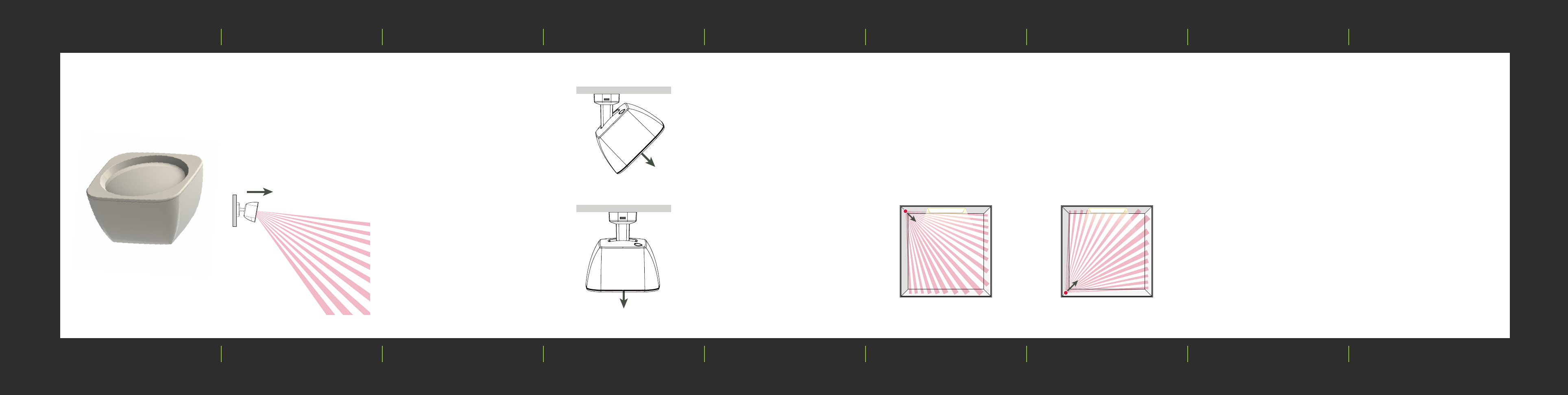
Basic rectangular-room
application: The sensor
“sees” within a 90° angle
(+/- 45° left/right from its
pointing direction (as
shown in top view Figure
1a), via a total of 80 fields of
view (“views”).
These views aim both
outward and downward
from the sensor (6° to 54°
or 11° to 59°) as shown in
side view Figure 1b.
Thus, an entire room (up to
20’ x 20’) can be covered
by mounting the sensor in
one corner, as shown in the
plan view figure 2a.
Occupancy is detected in
response to radiant-
temperature changes seen
within a view, for example,
when persons move into or
out of a view.
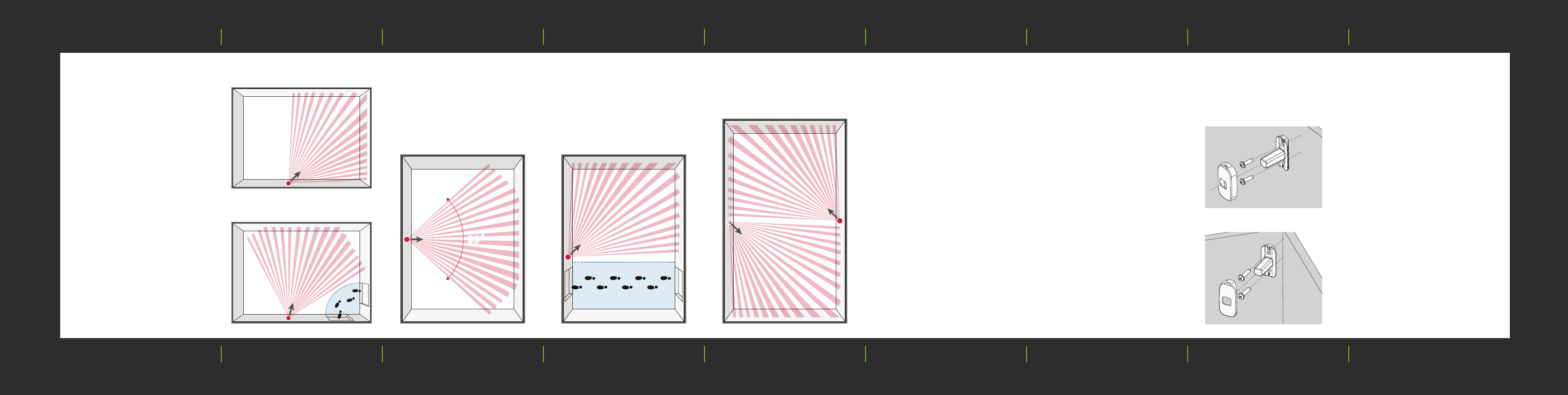
Figure 2a. Place sensor facing
away from large windows.
Figure 2b. Avoid sensor facing
large windows.
Orient the coverage-pattern
views so that they don’t
lead directly from the
sensor to items such as:
1. Larger (street-facing)
windows (Figure 2b)
2. Portable or wall-mounted
heaters
3. People in adjacent rooms
via doors wall openings.
Figure 1b.
Side view
Sensor at 10°
angle (See
mounting
proceedure.)
Figure 1a. Plan (Top) view
Sensor at 0° angle
Sensor at 45° angle
Sensor pointing
direction
FCC Interference Statement
This device complies with Part 15 of the
FCC Rules. Operation is subject to the
following two conditions: (1) This device
may not cause harmful interference, and (2)
this device must accept any interference
received, including interference that may
cause undesired operation.
This equipment has been tested and found
to comply with the limits for a Class B
digital device, pursuant to Part 15 of the
FCC Rules. These limits are designed to
provide reasonable protection against
harmful interference in a residential
installation. This equipment generates, uses
and can radiate radio frequency energy
and, if not installed and used in accordance
with the instructions, may cause harmful
interference to radio communications.
However, there is no guarantee that
interference will not occur in a particular
installation. If this equipment does cause
harmful interference to radio or television
reception, which can be determined by
turning the equipment off and on, the user
is encouraged to try to correct the
interference by one of the following
measures:
• Reorient or relocate the receiving
antenna.
• Increase the separation between the
equipment and receiver.
• Connect the equipment into an outlet on
a circuit different from that to which the
receiver is connected.
• Consult the dealer or an experienced
radio/TV technician for help.
FCC Caution: Any changes or
modifications not expressly approved by
the party responsible for compliance could
void the user's authority to operate this
equipment.
This transmitter must not be co-located or
operating in conjunction with any other
antenna or transmitter.
Radiation Exposure Statement: This
equipment complies with FCC radiation
exposure limits set forth for an uncontrolled
environment. This equipment should be
installed and operated with minimum
distance 20cm between the radiator and
your body.
Mounting height:
Choose a mounting height
between 6’ 6” and 10’ 6”.
(Preferred heights are 7’ 6”
and 10’ 0”.)
Mounting procedure:
The sensor’s bracket is
mounted by two screws
along a vertical line, as
shown in figure 8 and figure
9, either on a flat wall or in a
corner.
Use the provided drill
template, or mark two
positions, 7/8” (22mm)
apart, and drill two holes (xx
if anchors are used, or yy if
only screws will be used).
Note that the bracket’s
vertical angle is not 90°.
According to the mounting
height selected, orient the
bracket sloping upward
(number “5” up) or sloping
downward (number “10”
up). Figure 9 illustrates the
bracket with the number
“10” up.
6’ 6” – 8’ 6”
5 up (sensor facing
downward at 5° angle)
or
8’ 6” – 10’ 6”
10 up (sensor facing
downward at 10° angle)
Install the two screws to
fasten the bracket.
Install the wall-mount cover
(figure 8) or the corner-
mount cover (figure 9).
Figure 6 shows the sensor
rotated 45° on a flat-wall-
mounted bracket to ignore
motion within a non-entry
walking route.
Figure 7 shows a 20’ x 40’
room covered by 2 sensors.
Figure 5 shows the
coverage pattern with the
sensor mounted and
pointing straight outward in
a 16’ x 32’ room.
Coverage control for
specific applications:
In any mounting
configuration, the sensor
may be rotated in order to
provide defined detection
coverage. Several useful
configurations are possible
with the sensor mounted
on a flat wall.
Figure 3 shows a defined
coverage/non-coverage
pattern in a rectangular
room, with the sensor
rotated 45° on a flat-wall-
mounted bracket. Figure 4
shows a different rotation
position whereby the
sensor will ignore a non-
entry walking route.
Figure 3.
Figure 5. Figure 6.
Figure 7.
Figure 8.
Figure 9.
Figure 4.
90˚
Industry Canada Statement:
This device complies with RSS-210 of the
Industry Canada Rules. Operation is subject to
the following two conditions: (1) This device may
not cause harmful interference, and (2) this device
must accept any interference received, including
interference that may cause undesired operation.
Ce dispositif est conforme à la norme CNR-210
d'Industrie Canada applicable aux appareils radio
exempts de licence. Son fonctionnement est sujet
aux deux conditions suivantes: (1) le dispositif ne
doit pas produire de brouillage préjudiciable, et (2)
ce dispositif doit accepter tout brouillage reçu, y
compris un brouillage susceptible de provoquer
un fonctionnement indésirable.
Radiation Exposure Statement:
This equipment complies with IC radiation
exposure limits set forth for an uncontrolled
environment. This equipment should be installed
and operated with minimum distance 20cm
between the radiator & your body.
Déclaration d'exposition aux
radiations:
Cet équipement est conforme aux limites
d'exposition aux rayonnements IC établies pour
un environnement non contrôlé. Cet équipement
doit être installé et utilisé avec un minimum de 20
cm de distance entre la source de rayonnement
et votre corps.