Grizzly G0512 Manual User To The C30c2c63 214b 1a84 99a8 876c3c80fd09
User Manual: Grizzly G0512 to the manual
Open the PDF directly: View PDF ![]() .
.
Page Count: 44

COPYRIGHT © MAY, 2003 BY GRIZZLY INDUSTRIAL, INC.
WARNING: NO PORTION OF THIS MANUAL MAY BE REPRODUCED IN ANY SHAPE
OR FORM WITHOUT THE WRITTEN APPROVAL OF GRIZZLY INDUSTRIAL, INC.
#528603624 PRINTED IN TAIWAN
ONLINE MANUAL DISCLAIMER
THE INFORMATION IN THIS MANUAL REPRESENTS THE CONFIGURATION OF THE MACHINE AS IT IS CURRENTLY BEING SHIPPED. THE MACHINE
CONFIGURATION CAN CHANGE AS PRODUCT IMPROVEMENTS ARE INCORPORATED. IF YOU OWN AN EARLIER VERSION OF THE MACHINE, THIS
MANUAL MAY NOT EXACTLY DEPICT YOUR MACHINE . CONTACT CUSTOMER SERVICE IF YOU HAVE ANY QUESTIONS ABOUT DIFFERENCES. PRE-
VIOUS VERSIONS ARE NOT AVAILABLE ONLINE.
EDGE SANDER
MODEL G0512
INSTRUCTION MANUAL

WARNING
Some dust created by power sanding, sawing, grind-
ing, drilling, and other construction activities contains
chemicals known to the State of California to cause
cancer, birth defects or other reproductive harm.
Some examples of these chemicals are:
• Lead from lead-based paints.
• Crystalline silica from bricks, cement, and
other masonry products.
• Arsenic and chromium from chemically treated
lumber.
Your risk from these exposures varies, depending on
how often you do this type of work. To reduce your
exposure to these chemicals: work in a well ventilated
area, and work with approved safety equipment, such
as those dust masks that are specially designed to fil-
ter out microscopic particles.

SECTION 1: SAFETY........................................................................................................................2
Safety Instructions For Power Tools ..........................................................................................2
Additional Safety Instructions For Sanders ................................................................................4
SECTION 2: INTRODUCTION ..........................................................................................................5
SECTION 3: CIRCUIT REQUIREMENTS ........................................................................................6
Grounding....................................................................................................................................7
Extension Cords..........................................................................................................................7
SECTION 4: IDENTIFICATION ........................................................................................................8
SECTION 5: SET UP ........................................................................................................................9
Unpacking ..................................................................................................................................9
G0512 Inventory..........................................................................................................................9
Hardware Recognition Chart ....................................................................................................10
Clean Up ..................................................................................................................................11
Site Considerations ..................................................................................................................11
Beginning Assembly..................................................................................................................12
Installing Feet............................................................................................................................12
Installing Tension Lever ............................................................................................................13
Installing Sanding Belt ..............................................................................................................13
Attaching Dust Port ..................................................................................................................14
Installing Roller Guard ..............................................................................................................15
Test Run & Tracking ................................................................................................................15
Installing Table ..........................................................................................................................16
Installing Back Stop ..................................................................................................................18
Connecting to Dust Collection System......................................................................................18
SECTION 6: OPERATIONS ............................................................................................................19
Power Switch ............................................................................................................................19
Adjusting Table Height..............................................................................................................20
Sanding Belt Selection..............................................................................................................20
Edge & End Sanding ................................................................................................................21
Contour Sanding ......................................................................................................................22
SECTION 7: MAINTENANCE ........................................................................................................23
General......................................................................................................................................23
Table ........................................................................................................................................23
Lubrication ................................................................................................................................23
Sanding Belt..............................................................................................................................23
SECTION 8: SERVICE ADJUSTMENTS ........................................................................................24
About Service............................................................................................................................24
Adjusting Tensioner ..................................................................................................................24
Resetting Tensioner Spring Tension ........................................................................................25
Parallel Belt Tracking ................................................................................................................26
Platen-to-Rollers Adjustments ..................................................................................................28
SECTION 9: REFERENCE INFO ....................................................................................................31
Aftermarket Accessories ..........................................................................................................31
Machine Data Sheet..................................................................................................................32
Parts Breakdown and List ........................................................................................................33
Troubleshooting Machine..........................................................................................................35
Troubleshooting Sanding ..........................................................................................................36
G0512 Wiring Diagram..............................................................................................................37
Warranty and Returns ..............................................................................................................38
TABLE OF CONTENTS

-2- G0512 Edge Sander
5. KEEP CHILDREN AND VISITORS
AWAY. All children and visitors should be
kept at a safe distance from work area.
6. MAKE WORKSHOP CHILD PROOF with
padlocks, master switches, or by removing
starter keys.
7. NEVER FORCE TOOL. It will do the job
better and safer at the rate for which it was
designed.
8. USE RIGHT TOOL. DO NOT force tool or
attachment to do a job for which it was not
designed.
1. KEEP GUARDS IN PLACE and in working
order.
2. REMOVE ADJUSTING KEYS AND
WRENCHES. Form habit of checking to
see that keys and adjusting wrenches are
removed from tool before turning on.
3. KEEP WORK AREA CLEAN. Cluttered
areas and benches invite accidents.
4. NEVER USE IN DANGEROUS ENVI-
RONMENT. DO NOT use power tools in
damp or wet locations, or where any flam-
mable or noxious fumes may exist. Keep
work area well lighted.
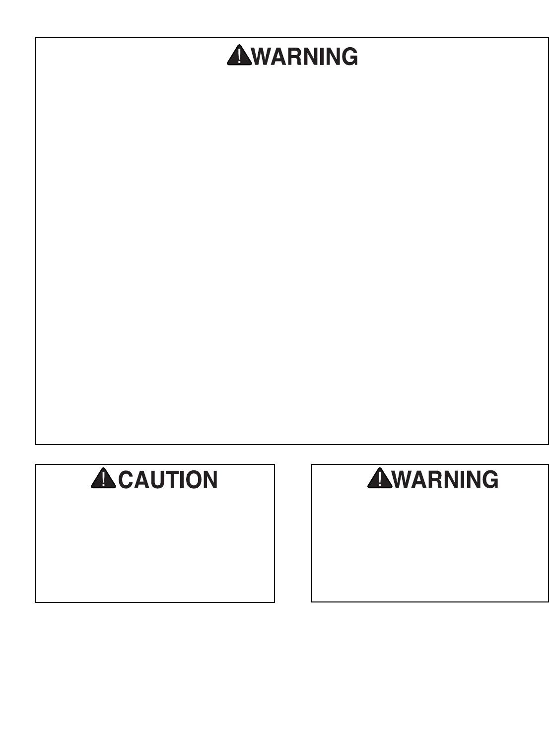
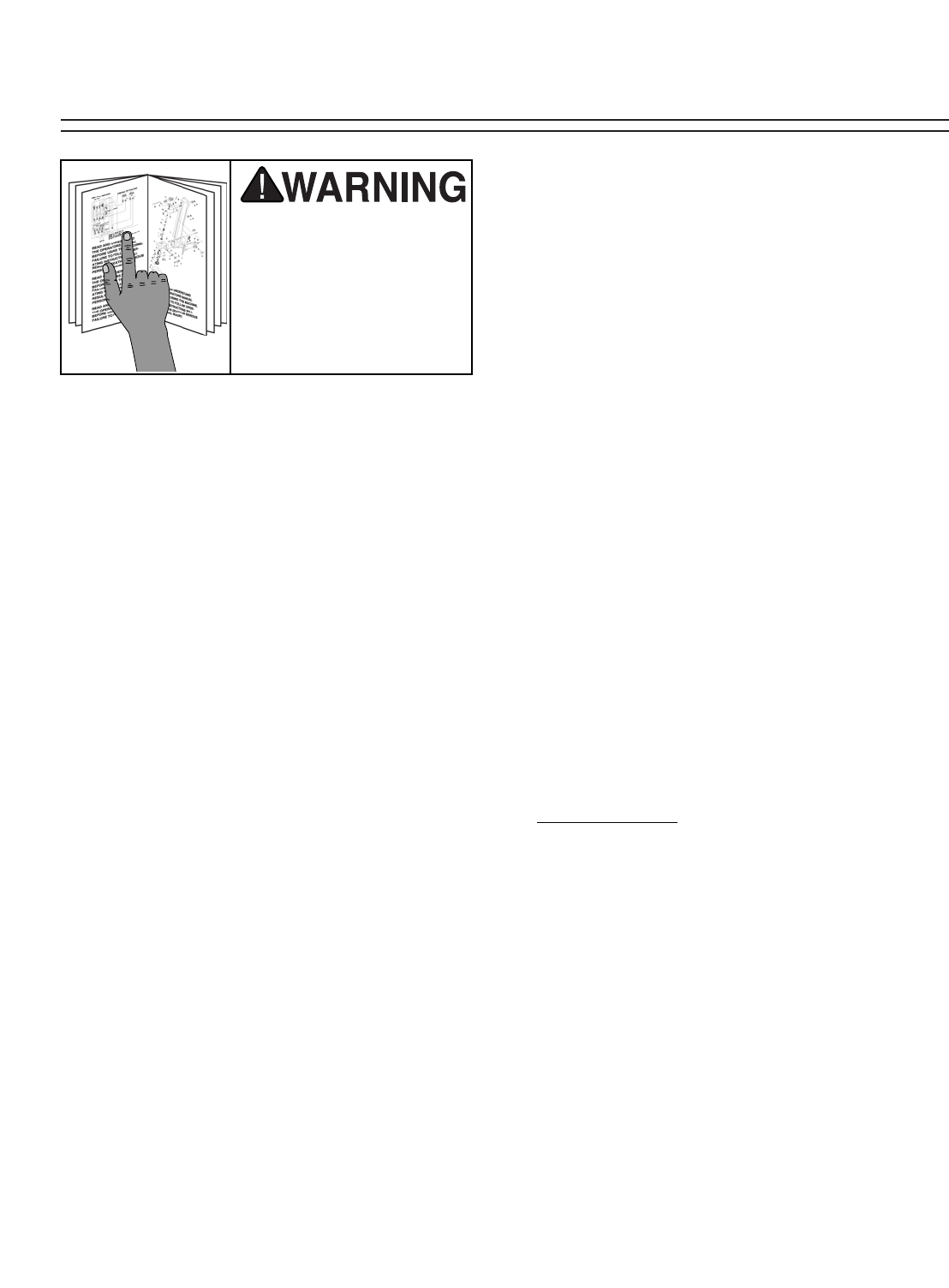
For Your Own Safety Read Instruction
Manual Before Operating This Equipment
Indicates an imminently hazardous situation which, if not avoided,
WILL result in death or serious injury.
Indicates a potentially hazardous situation which, if not avoided,
COULD result in death or serious injury.
Indicates a potentially hazardous situation which, if not avoided,
MAY result in minor or moderate injury. It may also be used to alert
against unsafe practices.
This symbol is used to alert the user to useful information about
proper operation of the equipment.
The purpose of safety symbols is to attract your attention to possible hazardous conditions.
This manual uses a series of symbols and signal words which are intended to convey the level
of importance of the safety messages. The progression of symbols is described below.
Remember that safety messages by themselves do not eliminate danger and are not a substi-
tute for proper accident prevention measures.
NOTICE
Safety Instructions For Power Tools
SECTION 1: SAFETY

G0512 Edge Sander -3-
9. USE PROPER EXTENSION CORD. Make
sure your extension cord is in good condi-
tion. Conductor size should be in accor-
dance with the chart below. The amperage
rating should be listed on the motor or tool
nameplate. An undersized cord will cause
a drop in line voltage resulting in loss of
power and overheating. Your extension
cord must also contain a ground wire and
plug pin. Always repair or replace exten-
sion cords if they become damaged.
Minimum Gauge for Extension Cords
10. WEAR PROPER APPAREL. DO NOT
wear loose clothing, gloves, neckties,
rings, bracelets, or other jewelry which may
get caught in moving parts. Non-slip
footwear is recommended. Wear protective
hair covering to contain long hair.
11. ALWAYS USE SAFETY GLASSES. Also
use face or dust mask if cutting operation is
dusty. Everyday eyeglasses only have impact
resistant lenses, they are NOT safety glasses.
12. SECURE WORK. Use clamps or a vise to hold
work when practical. It is safer than using your
hand and frees both hands to operate tool.
13. DO NOT OVER-REACH. Keep proper
footing and balance at all times.
14. MAINTAIN TOOLS WITH CARE. Keep
tools sharp and clean for best and safest
performance. Follow instructions for lubri-
cating and changing accessories.
LENGTH
AMP RATING 25ft 50ft 100ft
0-6 16 16 16
7-10 16 16 14
11-12 16 16 14
13-16 14 12 12
17-20 12 12 10
21-30 10 10 No
Safety Instructions For Power Tools
15. USE RECOMMENDED ACCESSORIES.
Consult the owner’s manual for recom-
mended accessories. The use of improper
accessories may cause risk of injury.
16. REDUCE THE RISK OF UNINTENTION-
AL STARTING. On machines with magnet-
ic contact starting switches there is a risk of
starting if the machine is bumped or jarred.
Always disconnect from power source
before adjusting or servicing. Make sure
switch is in OFF position before reconnecting.
17. CHECK DAMAGED PARTS. Before fur-
ther use of the tool, a guard or other part
that is damaged should be carefully
checked to determine that it will operate
properly and perform its intended function.
Check for alignment of moving parts, bind-
ing of moving parts, breakage of parts,
mounting, and any other conditions that
may affect its operation. A guard or other
part that is damaged should be properly
repaired or replaced.
18. NEVER LEAVE TOOL RUNNING UNAT-
TENDED. TURN POWER OFF. DO NOT
leave tool until it comes to a complete stop.
19. NEVER OPERATE A MACHINE WHEN
TIRED, OR UNDER THE INFLUENCE OF
DRUGS OR ALCOHOL. Full mental alert-
ness is required at all times when running a
machine.
20. NEVER ALLOW UNSUPERVISED OR
UNTRAINED PERSONNEL TO OPER-
ATE THE MACHINE. Make sure any
instructions you give in regards to machine
operation are approved, correct, safe, and
clearly understood.
21. IF AT ANY TIME YOU ARE EXPERIENC-
ING DIFFICULTIES performing the intend-
ed operation, stop using the machine! Then
contact our service department or ask a
qualified expert how the operation should
be performed.
-4- G0512 Edge Sander
Like all power tools, there is danger asso-
ciated with the Edge Sander. Accidents are
frequently caused by lack of familiarity or
failure to pay attention. Use this tool with
respect and caution to lessen the possibil-
ity of operator injury. If normal safety pre-
cautions are overlooked or ignored, seri-
ous personal injury may occur.
No list of safety guidelines can be complete.
Every shop environment is different. Always
consider safety first, as it applies to your
individual working conditions. Use this and
other machinery with caution and respect.
Failure to do so could result in serious per-
sonal injury, damage to equipment or poor
work results.
Additional Safety Instructions For Sanders
•DO NOT allow anyone to stand near the
sander while sanding wood stock.
•DO NOT jam the workpiece against the
sanding belt. Firmly grasp the workpiece in
both hands and ease it against the sanding
belt, using light pressure.
•DO NOT wear loose clothing while operat-
ing this machine. Roll up or button sleeves
at the cuff.
•DO NOT place hands near, or in contact
with, sanding belt during operation.
•ANY PROBLEM, with the exception of belt
tracking, that is concerned at all with any
moving parts or accessories must be
investigated and corrected with the power
disconnected, and after everything has
come to a complete stop.
•PERFORM machine inspections and main-
tenance service promptly when called for.
•NEVER leave the machine running unat-
tended.
•REPLACE sanding belt when it becomes
worn.
•NEVER sand more than one piece of stock
at a time.
•ALWAYS inspect board stock for nails,
staples, knots, and other imperfections that
could be dislodged and thrown from the
machine during sanding operations.
•NEVER operate the sander without an
adequate dust collection system in place
and running.
• NEVER sand tapered or pointed stock with
the point facing the feed direction.
•ALWAYSwear a dust mask when sand-
ing. Using this machine produces sawdust
which may cause allergic reactions or res-
piratory problems.
G0512 Edge Sander -5-
We are proud to offer the Model G0512 Edge
Sander. This Edge Sander is part of a growing
Grizzly family of fine woodworking machinery.
When used according to the guidelines set forth
in this manual, you can expect years of trouble-
free, enjoyable operation and proof of Grizzly’s
commitment to customer satisfaction.
This sander was developed for those projects
that require a large support area and need the
workpiece to be moved around the roller. The
specially designed small 21⁄2" edge diameter
roller allows you to get into tighter radius projects
like guitar bodies, curved chair legs etc.... The
table is supported in four positions to eliminate
sagging and to provide a stable base while
working, and the quick belt release mechanism
makes it easy to change belts fast.
We are pleased to provide this manual with the
Model G0512. It was written to guide you through
assembly, to review safety considerations, and to
cover general operating procedures. It repre-
sents our effort to produce the best documenta-
tion possible.
If you have any comments regarding this manual,
please write to us at the address below:
Grizzly Industrial, Inc.
C/OTechnical Documentation
P.O. Box 2069
Bellingham, WA 98227-2069
Most importantly, we stand behind our machines.
If you have any service questions or parts
requests, please call or write us at the location
listed below.
Grizzly Industrial, Inc.
1203 Lycoming Mall Circle
Muncy, PA 17756
Phone: (570) 546-9663
Fax: (800) 438-5901
E-Mail: techsupport@grizzly.com
Web Site: http://www.grizzly.com
The specifications, drawings, and photographs
illustrated in this manual represent the Model
G0512 as supplied when the manual was pre-
pared. However, owing to Grizzly’s policy of con-
tinuous improvement, changes may be made at
any time with no obligation on the part of Grizzly.
For your convenience, we always keep current
Grizzly manuals available on our website at
www.grizzly.com. Any updates to your machine
will be reflected in these manuals as soon as they
are complete. Visit our site often to check for the
latest updates to this manual!
SECTION 2: INTRODUCTION
Read the manual before
assembly and operation.
Serious personal injury
may result if safety or
operational information
is not understood or fol-
lowed.
-6- G0512 Edge Sander
SECTION 3: CIRCUIT REQUIREMENTS
Amperage Draw
The Model G0512 features a 110V/220V motor
that is prewired at 220V.
Motor Load at 220V ..............................10 amps
Motor Load at 110V ..............................20 amps
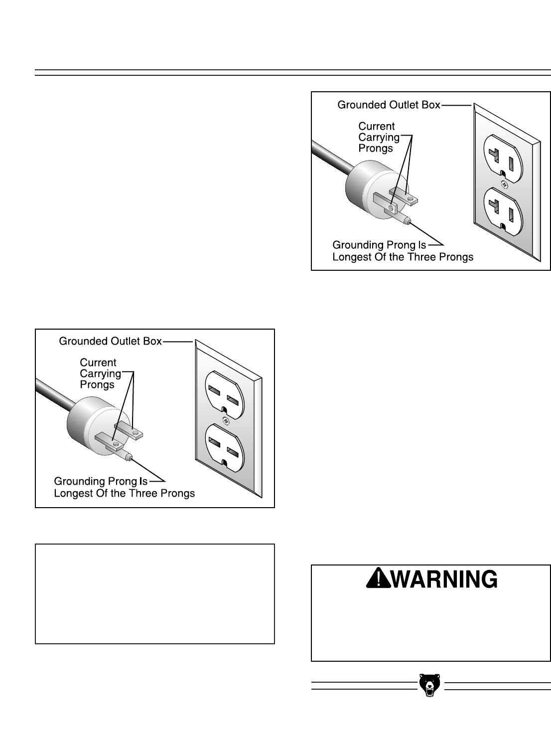
Plug Type
The cord set enclosed does not have a plug as
the style of plug you require will depend upon the
type of service you currently have or plan to
install. We recommend using the following plugs
for your machine on a dedicated circuit only (see
Figures 1 & 2 for an example):
220V Plug & Receptacle..............................6-15
110V Plug & Receptacle..............................5-20 Circuit Breaker Requirements
Please use the following guidelines when choos-
ing a circuit breaker for your machine (circuit
breakers rated any higher are not adequate to
protect the circuit):
220V Circuit Breaker ..............................10 amp
110V Circuit Breaker ..............................20 amp
Your Circuit Capacity
Always check to see if the wires in your circuit are
capable of handling the amperage load from your
machine. If you are unsure, consult a qualified
electrician. If you operate your sander on any cir-
cuit that is already close to its capacity, it might
blow a fuse or trip a circuit breaker. However, if
an unusual load does not exist and a power fail-
ure still occurs, contact a qualified electrician or
our Service Department.
Figure 1. 6-15 plug and receptacle.
Figure 2. 5-20 plug and outlet.
DO NOT connect your machine to the power
source until you have completed the assem-
bly process and have been instructed to do
so in this manual. Otherwise, serious per-
sonal injury could occur.
NOTICE
The Model G0512 is prewired for 220V oper-
ation. If you plan to rewire your machine for
110V, you must use a different switch.
Consult a licensed electrician before
attempting to rewire your machine!

G0512 Edge Sander -7-
In the event of an electrical short, grounding
reduces the risk of electric shock by providing a
path of least resistance to disperse electric cur-
rent. This tool is equipped with a power cord that
has a plug with an equipment-grounding prong.
The outlet must be properly installed and ground-
ed in accordance with all local codes and ordi-
nances.
This machine must have a ground prong in
the plug to help ensure that it is grounded.
DO NOT remove ground prong from plug to
fit into a two-pronged outlet! If the plug will
not fit the outlet, have the proper outlet
installed by a qualified electrician.
Electrocution or fire could
result if this machine is
not grounded correctly.
Make sure all electrical
circuits are grounded
before you connect them
to the machine. DO NOT
use this machine if it is
not grounded.
220V Operation
We do not recommend the use of extension cords
on 220V equipment. Instead, arrange the place-
ment of your equipment and the installed wiring to
eliminate the need for extension cords.
If you find it absolutely necessary to use an
extension cord at 220V with your Grizzly Edge
Sander:
• Make sure the cord is rated for Standard
Service (grade S) or better.
• The extension cord must also contain a
ground wire and plug prong.
• Use at least a 16 gauge cord if the cord is 50
feet long or less.
• Use at least a 14 gauge cord if the cord is
between 51-100 feet.
110V Operation
If you find it necessary to use an extension cord
at 110V with your Grizzly Edge Sander:
• Make sure the cord is rated Standard Service
(grade S) or better.
• The extension cord must also contain a
ground wire and plug pin.
• Use at least a 10 gauge cord if the cord is 50
feet long or less.
• DO NOT use a cord longer that 50 feet!
Extension CordsGrounding
-8- G0512 Edge Sander
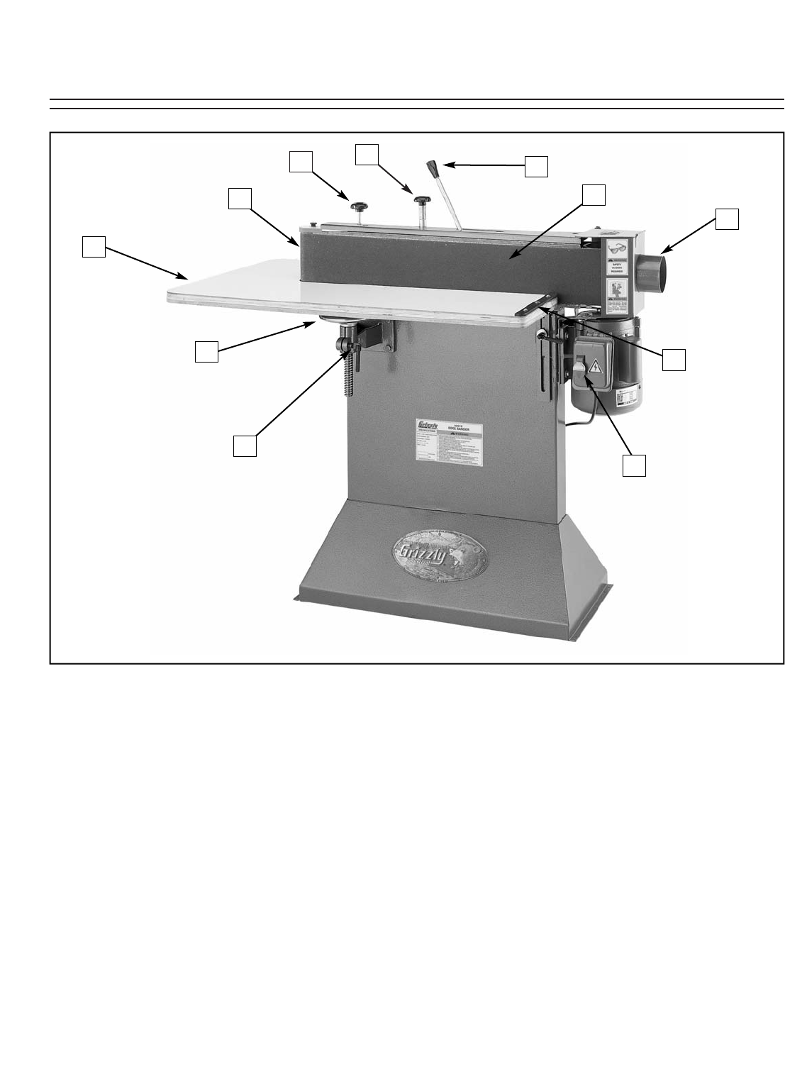
Figure 3. The following is a list of controls and components on the Model G0512. Please take time to
become familiar with each item and its location. These items will be used throughout the manual and know-
ing them is essential to understanding the instructions and terminology used in this manual.
1. Belt Tracking Knob
2. Tracking Lock
3. Contour Sanding Area
4. Sanding Table
5. Table Elevation Handwheel
6. Lead Screw Lock Handle
7. ON/OFF Switch
8. Back Stop
9. Dust Port
10. Flat Sanding Area
11. Belt Tension Lever
SECTION 4: IDENTIFICATION
21
3
5
4
8
6
7
10
9
11
G0512 Edge Sander -9-
The Model G0512 was carefully packed when it
left our warehouse. If you discover the machine is
damaged after you have signed for delivery,
please immediately call Customer Service at
(570) 546-9663 for advice.
Save the containers and all packing materials for
possible inspection by the carrier or its agent.
Otherwise, filing a freight claim can be difficult.
When you are completely satisfied with the con-
dition of your shipment, you should inventory the
contents.
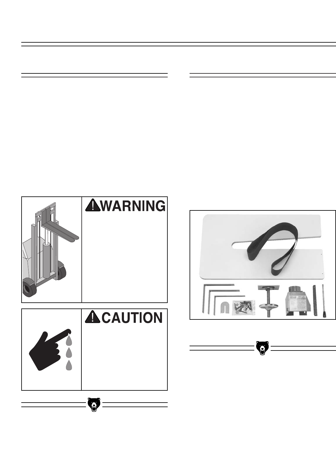
Some metal parts may
have sharp edges on
them after they are
formed. Please examine
the edges of all metal
parts before handling
them. Failure to do so
could result in injury.
• G0512 Sander Unit ....................................1
• Wood Table ................................................1
• Dust Port ....................................................1
• Lead Screw Bracket Assembly ..................1
• L Support ....................................................2
• Front L Support Assembly ..........................1
• Back Stop....................................................1
• Lever Handle ..............................................1
• 6" x 80" Sanding Belt ..................................1
• Idler Roller Cover ........................................1
• Small Star Knob ..........................................1
• Hardware Bag ............................................1
—Lock Handle ............................................3
—Flat Washer 3⁄8"........................................6
—Plastic Feet..............................................4
—Phillips Head Screw #10-24 x 5⁄8"............4
—Phillips Head Tap Screws #8 x 3⁄4" ........19
The Edge Sander is a
heavy machine at
approx. 250 lbs. ship-
ping weight. DO NOT
move the machine by
yourself – you will need
assistance or power
equipment. Serious per-
sonal injury may occur if
safe moving methods
are not followed.
Figure 4. Model G0512 packaging inventory.
G0512 InventoryUnpacking
SECTION 5: SET UP

-10- G0512 Edge Sander
Hardware Recognition Chart

G0512 Edge Sander -11-
Floor Load
The Model G0512 weighs 235 lbs. and has a
141⁄2" x 32" footprint on the bottom of the stand.
Most commercial floors are suitable for your
machine. Some residential floors may require
additional build up to support both the machine
and operator.
Working Clearances
Consider existing and anticipated needs, size of
material to be processed through each machine,
and space for auxiliary stands, work tables or
other machinery when establishing a location for
your bandsaw.
Lighting and Outlets
Lighting should be bright enough to eliminate
shadow and prevent eye strain. Electrical circuits
should be dedicated or large enough to handle
amperage requirements. Outlets should be locat-
ed near each machine so power or extension
cords are clear of high-traffic areas. Observe
local electrical codes for proper installation of
new lighting, outlets, or circuits.
The unpainted surfaces are coated with a waxy
oil to protect them from corrosion during ship-
ment. Remove this protective coating with a sol-
vent cleaner or citrus-based degreaser such as
Grizzly’s G7895 Degreaser. To clean thoroughly,
some parts may need to be removed. For opti-
mum performance from your machine, make
sure you clean all moving parts or sliding
contact surfaces that are coated. Avoid chlo-
rine-based solvents as they may damage painted
surfaces should they come in contact.
Do not use gasoline or
other petroleum-based
solvents to clean with.
They have low flash
points which make them
extremely flammable. A
risk of explosion and
burning exists if these
products are used.
Do not smoke while using
solvents. A risk of explo-
sion or fire exists and may
result in serious personal
injury.
Site ConsiderationsClean Up
Many of the solvents
commonly used to clean
machinery can be toxic
when inhaled or ingest-
ed. Lack of ventilation
while using these sol-
vents could cause seri-
ous personal health risks
or fire. Take precautions
from this hazard by only
using cleaning solvents
in a well ventilated area.
Unsupervised children and
visitors inside your shop
could cause serious person-
al injury to themselves. Lock
all entrances to the shop
when you are away and DO
NOT allow unsupervised
children or visitors in your
shop at any time!
-12- G0512 Edge Sander
This section will cover the minimum assembly
and adjustment instructions needed to begin
operation. For best results, complete the assem-
bly in the order provided in this manual and then
read the remaining portion of the manual before
attempting any type of operations.
Safety must come first! Read and follow these
instructions before beginning assembly:
Most of your Edge Sander has been assembled
at the factory, but some parts must be assembled
or installed after delivery.
Some metal parts may
have sharp edges on
them after they are
formed. Please examine
the edges of all metal
parts before handling
them. Failure to do so
could result in injury.
Disconnect power to the
machine when perform-
ing all assembly steps.
Failure to do this may
result in serious person-
al injury.
Wear safety glasses dur-
ing the entire assembly
process. Failure to com-
ply may result in serious
personal injury.
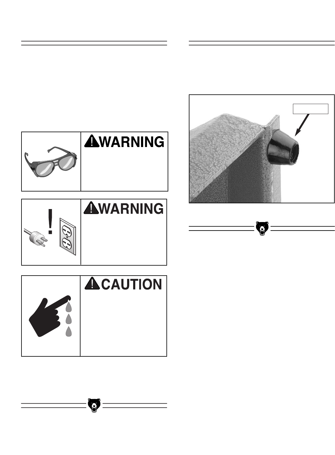
To install the feet on the sander:
1. Thread the feet into the bottom of the stand
as shown in Figure 5.
Figure 5. Stand foot threaded onto stand.
Installing FeetBeginning Assembly
Stand Foot
G0512 Edge Sander -13-
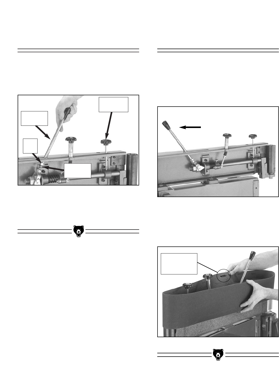
To install the sanding belt:
1. Make sure the tension lock knob is loosened.
2. Move the tension lever into the release posi-
tion as shown in Figure 7.
Figure 7. Tension lever in release position.
Figure 8. Installing sanding belt.
3. Make sure the arrows on the inside of the
belt point in the counter-clockwise direction,
and place the sanding belt over both rollers
as shown in Figure 8.
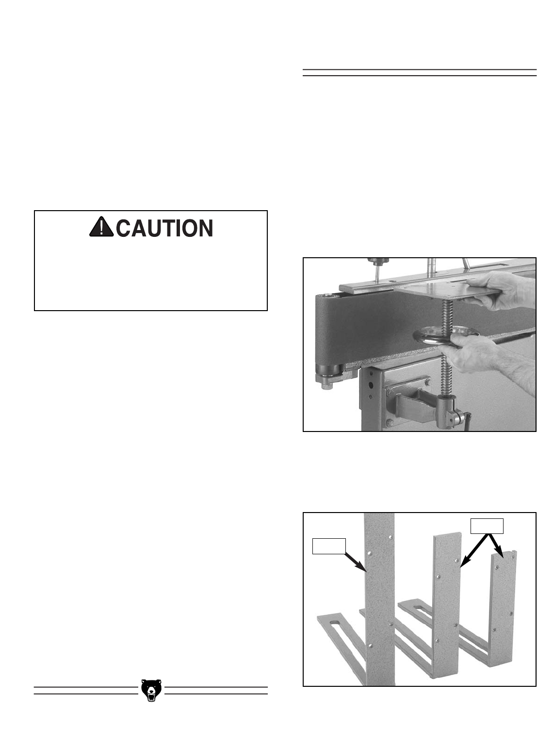
To install the tension lever:
1. Thread the end of the tension lever into the
swivel assembly as shown in Figure 6.
Figure 6. Installing tension lever in swivel
assembly.
2. Tighten the lock nut against the swivel
assembly to secure the tension lever.
Installing Sanding
Belt
Installing Tension
Lever
Swivel
Assembly
Tension
Lever
Lock
Nut
Notice Arrow
Direction on
Belt
Tension
Lock Knob

-14- G0512 Edge Sander
Figure 9. Dust port attached to brackets.
To attach the dust port:
1. Attach the dust port to the support brackets
with the three 5⁄16"-18 x 1⁄2" hex bolts and
washers, as shown in Figure 9, but DO NOT
completely tighten the bolts yet.
2. Position the dust port approximately 1⁄2" away
from the driver roller and tighten the two
attachment bolts from step 1.
The voltage you decide to use with your sander
will determine which plug and receptacle you
install. Read pages 6 & 7, in Section 3: Circuit
Requirements for more information.
Install the plug and receptacle now.
Connecting Plug to
Cord
Attaching Dust Port
G0512 Edge Sander -15-
Figure 11. Sanding belt even with
top of main roller.
Figure 10. Idler roller guard installed and
secured in position with small star knob.
Before you can install the table, you must run the
sander to track the belt. However, you should
perform a “pre-tracking” procedure before starting
the sander to ensure that the belt does not come
off of or bottom out on the rollers during the initial
startup.
To pretrack the belt:
1. Make sure that the sander is disconnect-
ed from the power!
2. Loosen the tracking lock knob.
3. Standing in front of the sander, push the
sanding belt multiple times along the platen,
so that it moves in the direction of operation
(counter-clockwise on the rollers), and watch
how the belt tracks on the rollers.
4. Adjust the tracking higher or lower as need-
ed and continue to rotate the belt by hand.
5. Repeat steps 3 & 4 until the top of the sand-
ing belt rides even with the top of the main
roller as shown in Figure 11.
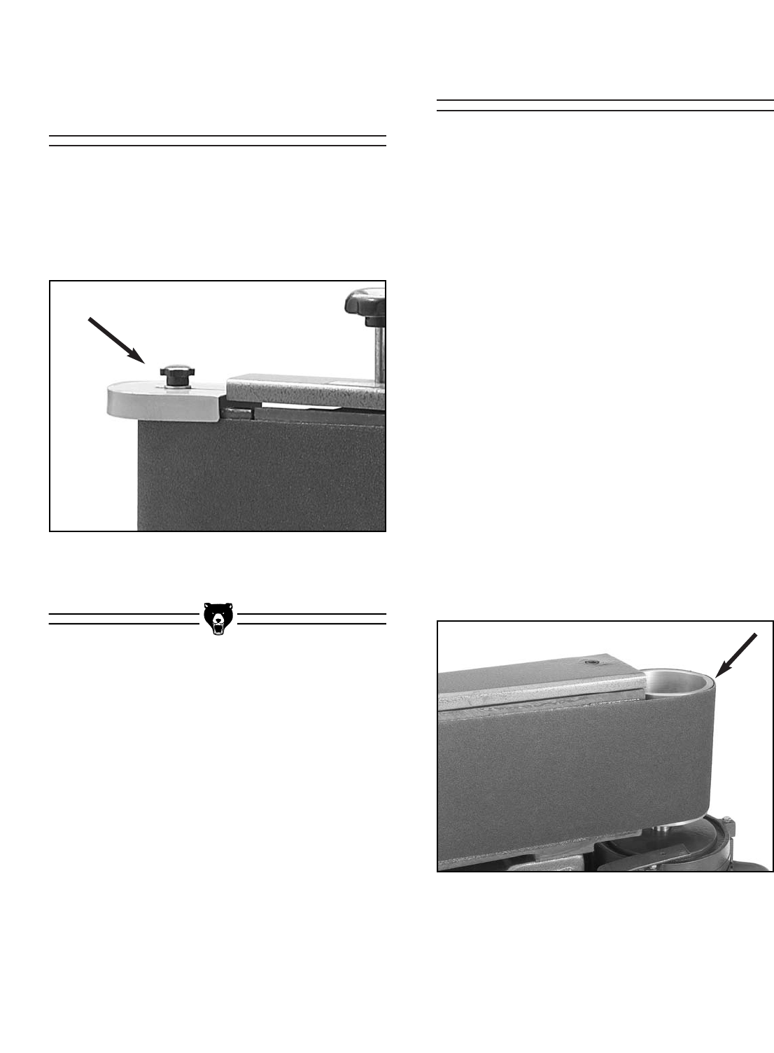
To install the roller guard:
1. Place the guard on top of the idler roller and
secure it in position with the included small
star knob, as shown in Figure 10.
Test Run & TrackingInstalling Roller
Guard
-16- G0512 Edge Sander
Installing Table
To test run and track the belt:
1. Make sure the belt is properly pre-tracked as
described previously.
2. Tie back loose clothing and long hair to pro-
tect yourself from getting caught in the mov-
ing sanding belt when you start the machine.
3. Make sure the switch is in the down position
(OFF), then connect the sander to the power
source.
Use extreme caution when preparing for
your initial test run. Always keep one finger
on the switch in order to quickly STOP the
machine in the event of a malfunction or
incorrect belt tracking.
4. Start the sander; it should run smoothly with
little or no vibration or rubbing noises.
Strange or unnatural noises should be inves-
tigated and corrected before further opera-
tion.
— If noises occur that can not be found by
visual inspection, feel free to contact our
Service Department for help.
5. Using the tracking control knob, carefully
adjust the tracking higher or lower until the
top of the sanding belt remains even with the
top of the main roller. Note—The tracking
control knob is very sensitive, adjust it with
caution.
6. When the tracking appears to be correct,
allow the sander to run for approximately one
minute to verify that the tracking stays in the
correct position.
— If the tracking does not stay correct,
repeat steps 5 & 6.
7. When the sanding belt is tracking correctly,
tighten the tracking lock knob.
Before installing the table, the sanding belt must
be tracking correctly to ensure that the idler roller
is close to the position that it will be in during
operation.
To install the table:
1. Disconnect the sander from the power
source!
2. Insert the lead screw assembly as shown in
Figure 12.
Figure 12. Lead screw assembly installed in
bracket.
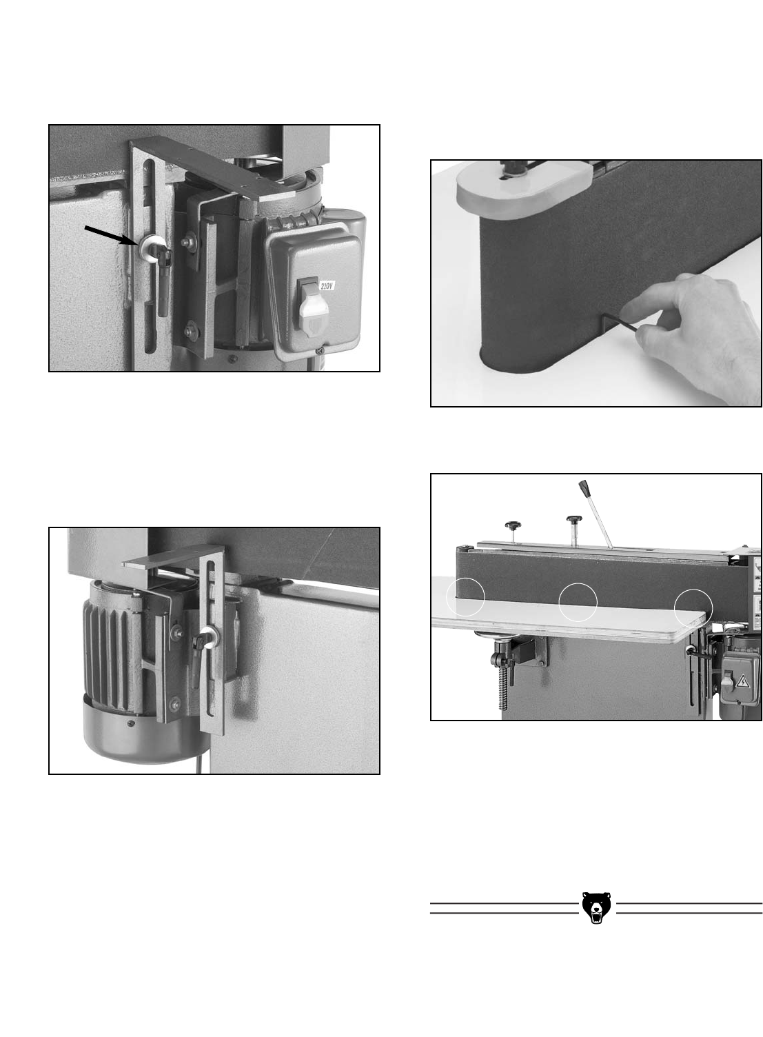
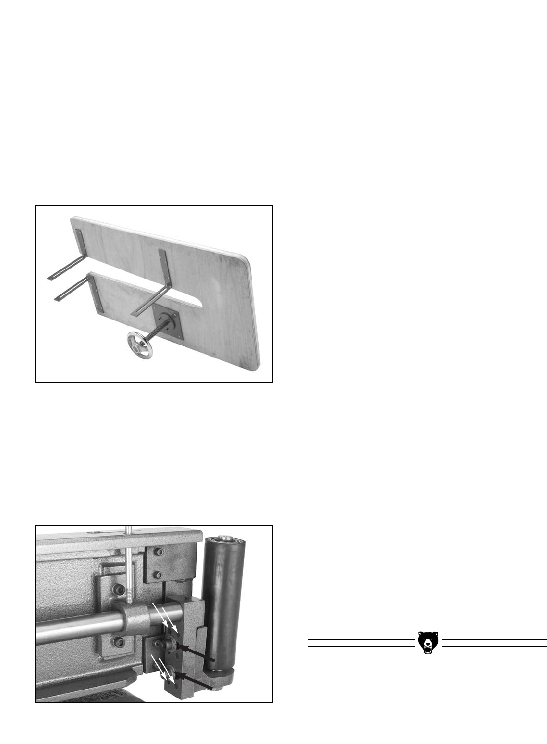
Figure 13. Table brackets laid out for
identification.
3. Identify the three table brackets in Figure 13
before continuing.
Front
Rear
G0512 Edge Sander -17-
Figure 14. Front L support installed.
Figure 16. Allen wrench placed between platen
and table.
Figure 17. Three places to ensure the spacing
between the sanding belt and the table is even.
4. Install the front L support with the lock han-
dle and two 3⁄8" flat washers as shown in
Figure 14.
5. Install the L supports with the lock handles
and remaining four 3⁄8" flat washers as shown
in Figure 15. The smallest L support at the
rear of the machine should be closest to the
motor.
6. Lower the lead screw support all the way
down and adjust all of the L support brackets
up to approximately the same height. This
will prepare the brackets for the table place-
ment.
7. Place the table on the supports.
8. Use a 3mm or 1⁄8" Allen wrench as a gauge to
position the table evenly away from the plat-
en and the idler roller. Do this by placing the
Allen wrench as shown in Figure 16, at the
three locations shown in Figure 17.
9. Clamp the table to the supports or have an
assistant hold the table in place, and secure
the table to the supports with the #8 x 3⁄4"
Phillips head tap screws provided in the
hardware bag.
Figure 15. Rear L supports installed.
-18- G0512 Edge Sander
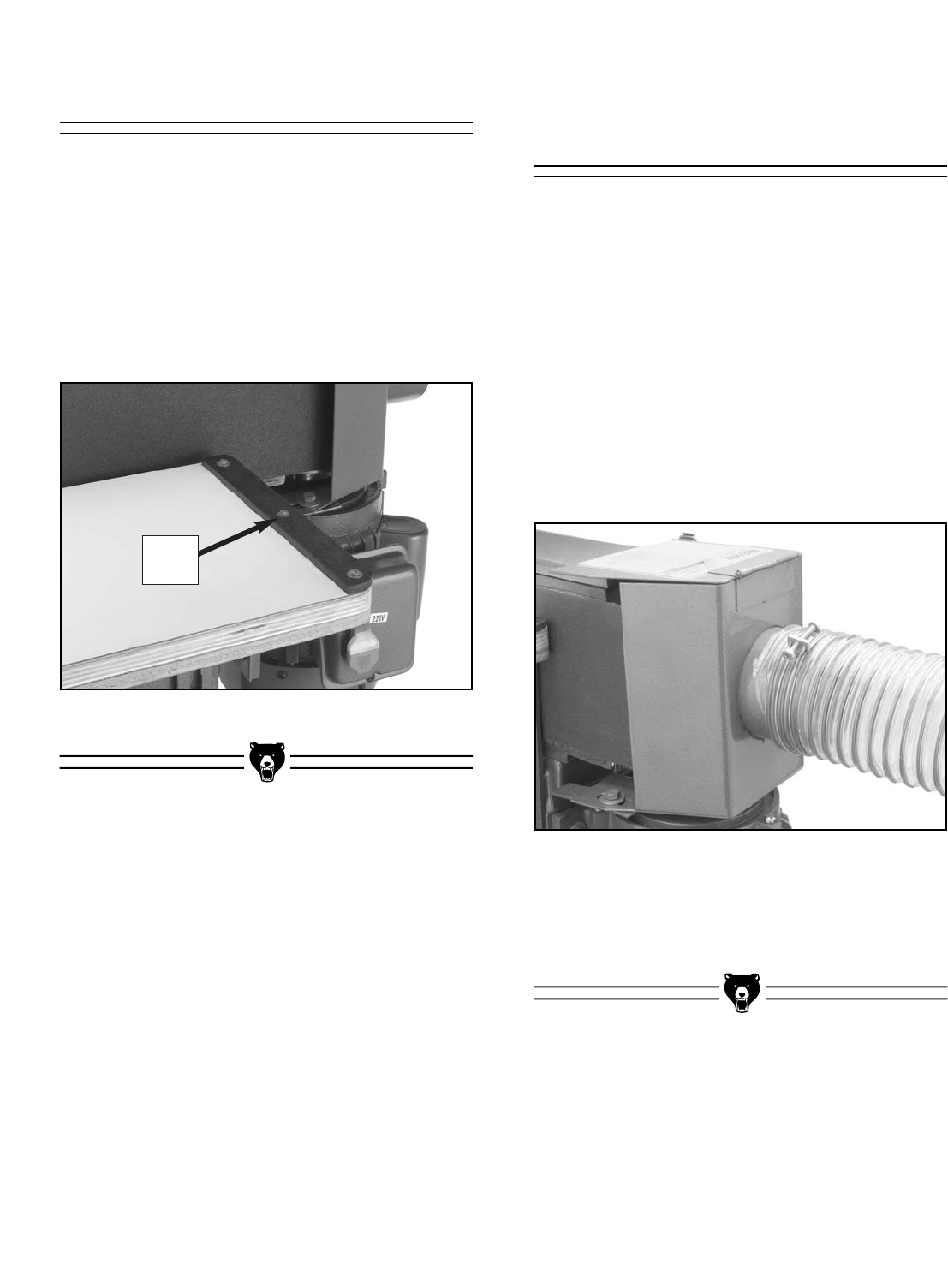
To install the back stop:
1. Use a machinists square to position the back
stop perpendicular to the platen, on the end
of the table that is near the ON/OFF switch.
2. Secure the backstop to the table with three
#8 x 3⁄4" Phillips head tap screws (as shown
in Figure 18).
Figure 18. Back stop mounted on table.
The dust port can be connected to a dust collec-
tion system with a 4" hose. However, in order to
move the dust from the sander, the dust collec-
tion system must be able to move approximately
500 CFM where the hose connects to the dust
port. Note—This number is an approximation and
is used for estimation purposes only.
To connect the dust port to a dust collection
system:
1. Slide the 4" hose completely over the dust
port as shown in Figure 19.
Figure 20. Dust port connected to dust
collection system.
2. Tighten the hose clamp to ensure a snug,
sealed fit.
Connecting to Dust
Collection System
Installing Back Stop
Back
Stop

G0512 Edge Sander -19-
Keep loose clothing out
of the way of machinery
and keep hair pulled
back during operations.
Your safety is important! Please follow the
warnings below:
Operating this equipment creates the
potential for flying debris to cause eye
injury. Always wear safety glasses when
operating equipment. Everyday glasses or
reading glasses only have impact resistant
lenses, they are not safety glasses. Be cer-
tain the safety glasses you wear meet the
appropriate standards of the American
National Standards Institute (ANSI).
Sanding surfaces are capable of causing
serious personal injury if they come in con-
tact with fingers, hands, or other body
parts. Use extreme care to provide a large
buffer area between the sanding belt and
any part of your body.
Using this machine pro-
duces sawdust that may
cause short and long-
term respiratory illness.
Always wear a dust mask
when operating this
machine.
Besides starting and stopping the sander, the
power switch features an important safety lockout
key. This key can be removed (as shown in
Figure 21) to disable the sander so that it cannot
be accidentally started.
Figure 21. Safety key removed from switch.
Power Switch
SECTION 6: OPERATIONS
-20- G0512 Edge Sander
The Model G0512 accepts a 6" x 80" sanding
belt.
There are many types of sanding belts to choose
from. We recommend Aluminum Oxide for gener-
al workshop environments. Below is a chart that
groups abrasive types into different classes, and
shows which grits fall into each class.
The general rule of thumb is to sand a workpiece
with progressively higher grit numbers, with no
one grit increase of more than 50.
Grit Type
60
80-100
120-180
220
Coarse
Medium
Fine
Very Fine
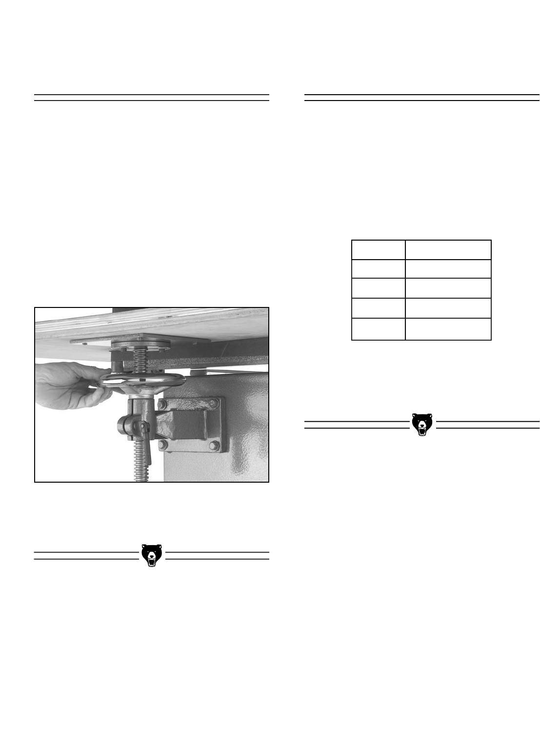
Figure 22. Lead screw handwheel.
The table can be adjusted up or down to allow the
operator to use more surface area of the sanding
belt. Adjusting the height will also prevent the
platen graphite and sanding belt from wearing out
in one place.
To adjust the table:
1. Loosen the lock handles that secure the L
supports and the lead screw.
2. Turn the lead screw handwheel (shown in
Figure 22) to raise or lower the table to the
desired height.
3. Tighten all of the lock handles.
Sanding Belt
Selection
Adjusting Table
Height
G0512 Edge Sander -21-
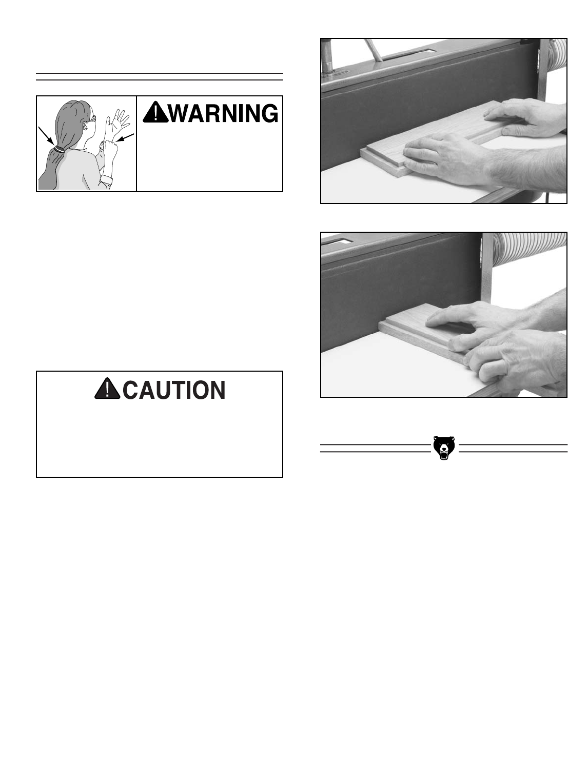
Edge & End Sanding
To perform an edge or end sanding operation:
1. Make sure the vertical tracking on the sand-
ing belt is set.
2. Start the sander by pulling the switch up.
3. Support the workpiece against the back stop,
keep your fingers away from the moving belt
and slowly feed the workpiece into the mov-
ing belt, as shown in Figures 23 & 24.
Figure 23. Typical edge sanding operation.
Figure 24. Typical end sanding operation.
Keep loose clothing out
of the way of machinery
and keep hair pulled
back during operations!
If you must feed a workpiece into the sand-
ing belt corner first, feed the trailing corner
first. Feeding the leading corner first, could
cause the sanding belt to grab the work-
piece and jerk it out of your hands.
-22- G0512 Edge Sander
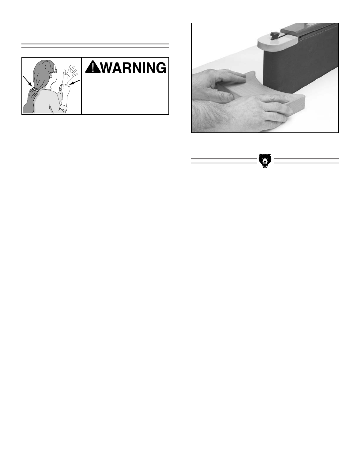
Contour Sanding
To perform a contour sanding operation:
1. Start the sander by pulling the switch up.
2. Grip the workpiece firmly and feed it into the
curved end (as shown in Figure 25), and
continue moving the workpiece profile along
the contour until you achieve your desired
shape.
Figure 25. Typical contour sanding operation.
Keep loose clothing out
of the way of machinery
and keep hair pulled
back during operations!

G0512 Edge Sander -23-
Disconnect power to the
machine when perform-
ing any adjustments or
maintenance. Failure to
do this may result in seri-
ous personal injury.
Regular periodic maintenance on your Grizzly
Edge Sander will ensure its optimum perfor-
mance. Make a habit of inspecting your sander
each time you use it. Check for the following con-
ditions and repair or replace when necessary.
1. Loose mounting bolts.
2. Worn switch.
3. Worn or damaged cords and plugs.
4. Any other condition that could hamper the
safe operation of this machine.
Bearings
Since all bearings are shielded and permanently
lubricated, simply leave them alone until they
need to be replaced. DO NOT lubricate them.
Table Height Lead Screw
Wipe off built-up sawdust and lubricate with an
occasional shot of white lithium grease. After
lubricating, be sure to move the lead screw
through the full range of motion that it can travel,
so that the grease is spread evenly.
The sanding belt should be regularly cleaned as
it becomes clogged with sawdust. Clean the
sanding belt with PRO STIK®belt cleaners
(Model G1511/G1512). Belts that are regularly
cleaned have a much longer useful life, than belts
that are neglected. See page 31 for more detail
on PRO STIK™belt cleaners.
The laminate surface on the table can be wiped
clean with a dry towel or cleaned with a solvent
designed to remove wood resins if the table is
gummy.
DO NOT expose the underside of the table to
water because it may warp.
Sanding Belt
Lubrication
Table
General
SECTION 7: MAINTENANCE
-24- G0512 Edge Sander
Disconnect power to the
machine when perform-
ing any adjustments or
maintenance. Failure to
do this may result in seri-
ous personal injury.
This section is designed to help the operator with
adjustments that were made at the factory and
might also need to be made during the life of the
machine.
This section is provided for your convenience—it
is not a substitute for the Grizzly Service
Department. If any adjustments arise that are not
described in this manual, then feel free to call the
Grizzly Service Department.
Similarly, if you are unsure of how to perform any
procedure in this section, the Grizzly Service
Department will be happy to guide you through
the procedures or help in any other way.
The belt tensioner is normally adjusted as the belt
stretches. Two good indications of belt stretch (or
a loose belt) are if the belt slaps against the plat-
en while running or if it slips on the rollers.
On the other hand, if the belt tension is too tight,
you will have a hard time installing and removing
the belt when the belt tension is released.
To adjust the belt tensioner:
1. Disconnect the sander from the power
source!
2. Lower the table as far as it will go.
3. Loosen the tracking lock knob, release the
belt tension, and remove the sanding belt
from the sander.
4. Move the belt tension lever to the position
where the belt is normally tensioned.
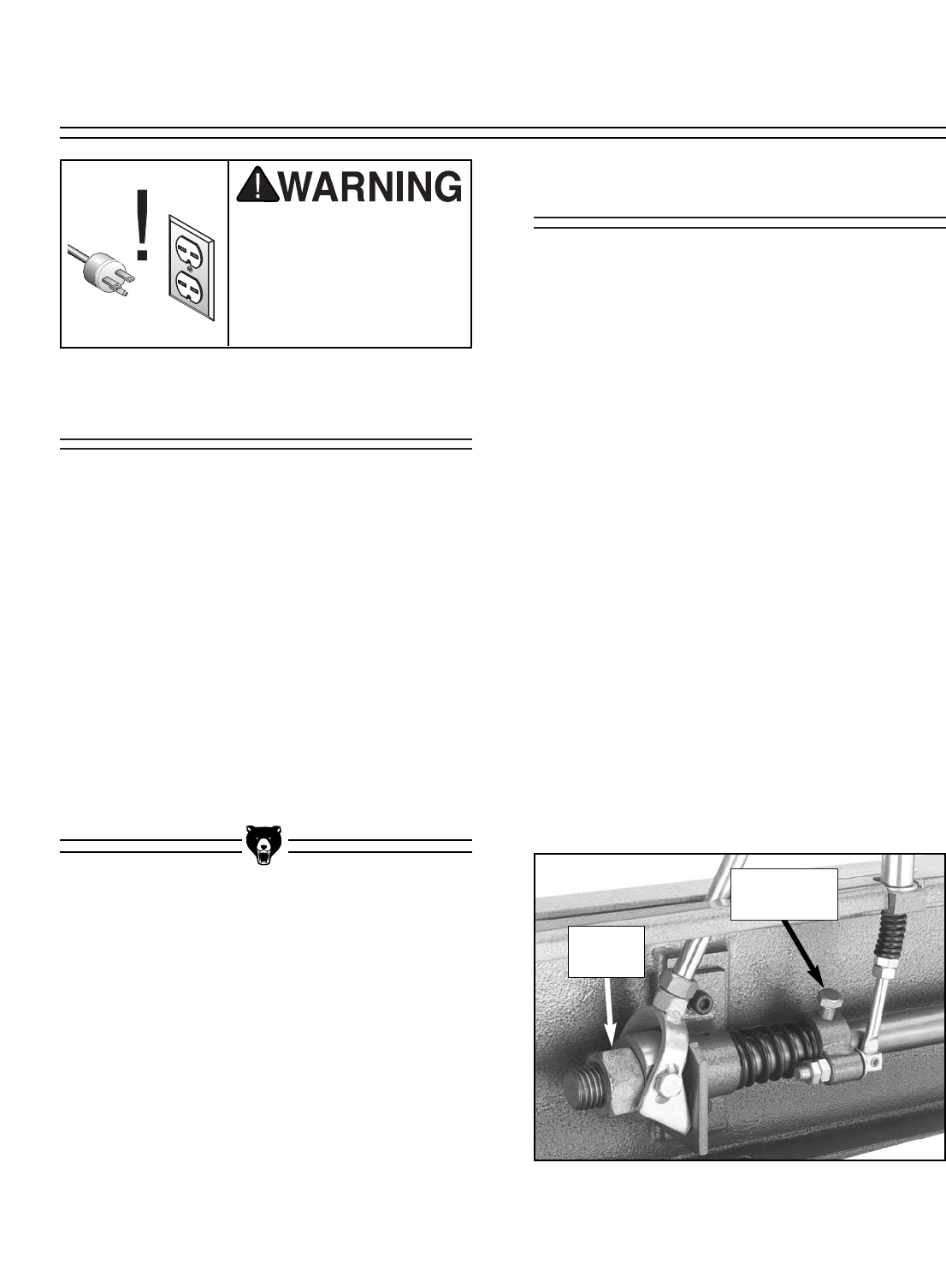
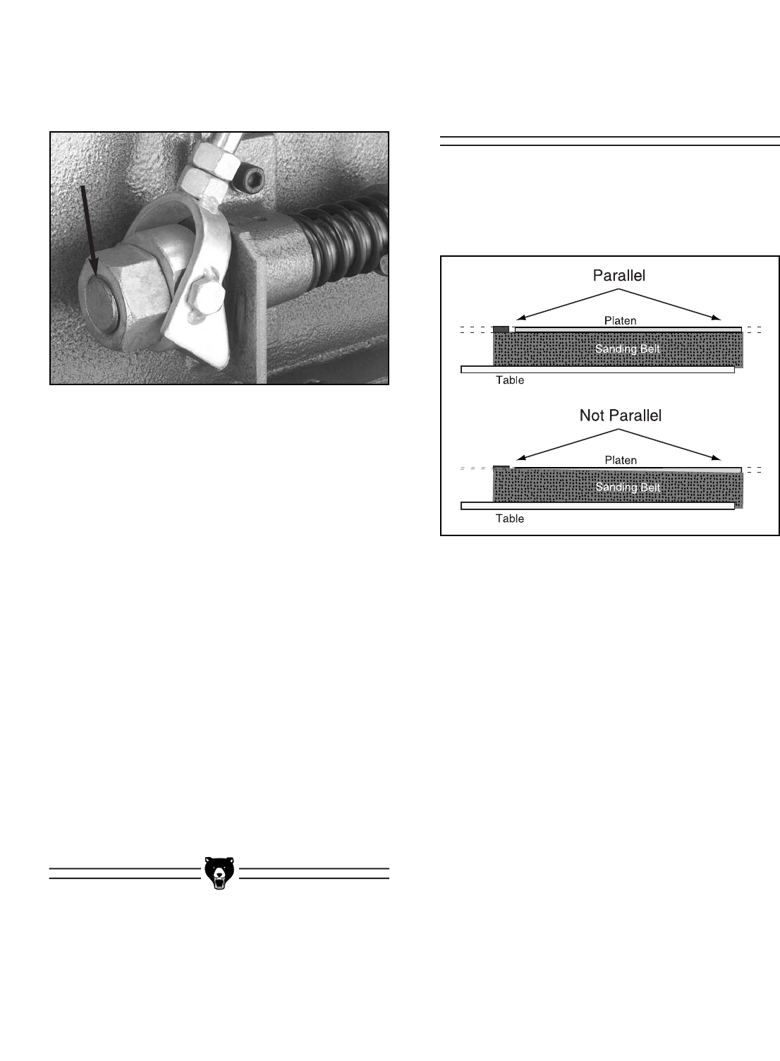
5. Locate the belt tension nut and the tracking
control bolt shown in Figure 35.
Figure 35. Belt tension nut and tracking
control bolt.
Adjusting Tensioner
About Service
SECTION 8: SERVICE ADJUSTMENTS
Tracking
Control Bolt
Tension
Nut
G0512 Edge Sander -25-
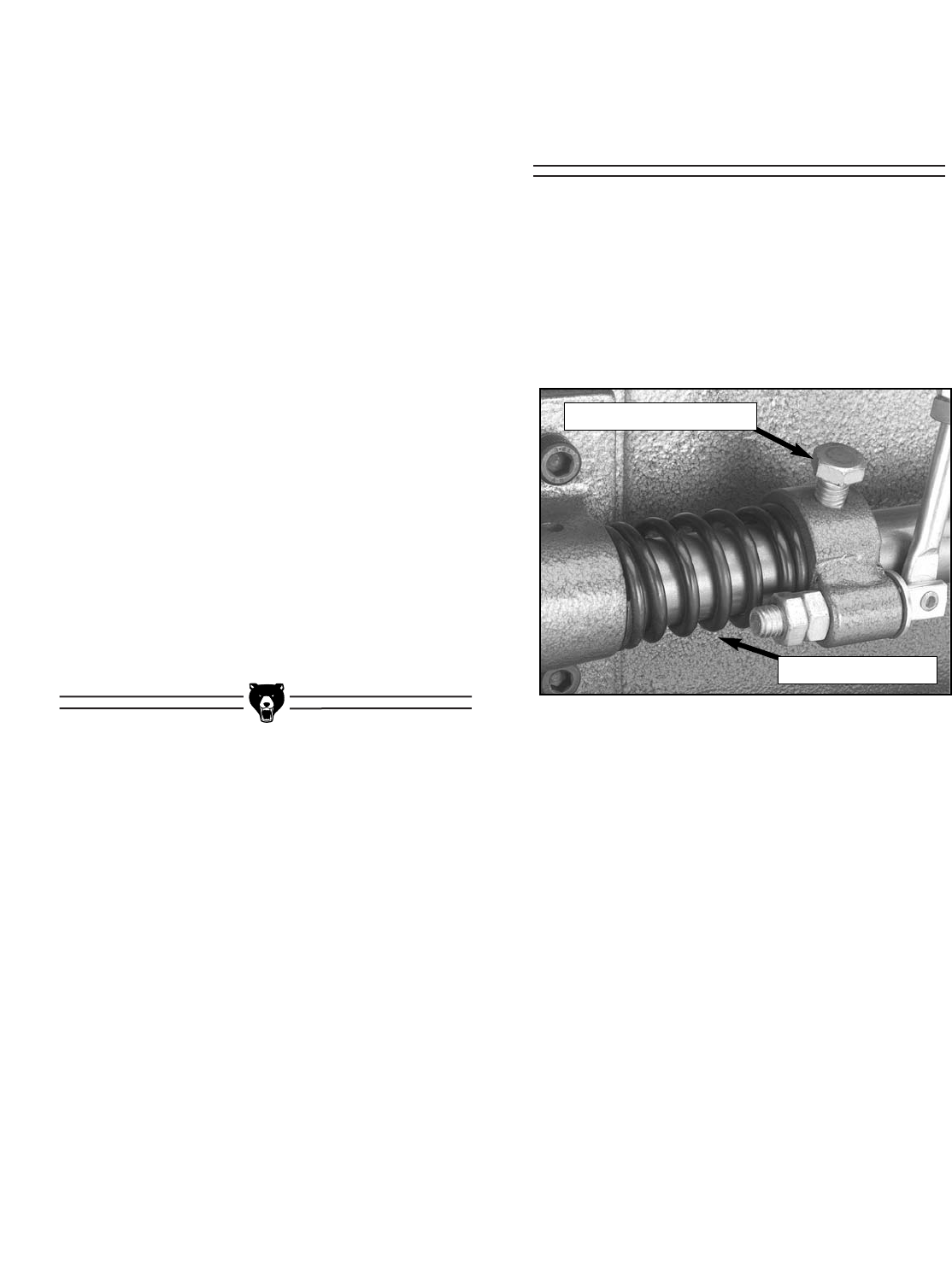
Resetting Tensioner
Spring Tension
Figure 36. Tensioner spring and
tracking control bolt.
6. Rotate the tension nut counter-clockwise to
increase the tension and clockwise to
decrease the tension.
—Decreased Tension: If you rotated the
tension nut clockwise, move the belt ten-
sion lever to the release position. If it is
not too stiff, continue to step 7. If it is too
stiff to move comfortably, then either the
shaft spring tension needs to be reset, the
tension shaft needs lubrication, or the
idler roller-to-platen relationship needs to
be adjusted (page 29-30).
—Increased Tension: If you rotated the ten-
sion nut counter-clockwise, check the
beginning movement of the belt tension
lever. If there is no play in the first 2" of
travel, continue to step 7. If there is play
in the first 2", then the tension shaft spring
tension needs to be reset, as described in
the next sub-section.
7. Replace the sanding belt and examine the
effect of the tension adjustment on your belt.
Repeat the adjustment procedure if neces-
sary.
The tensioner spring (shown in Figure 36)
applies pressure to the sanding belt when the
belt tension lever is in the tension position. When
repeated adjustments are made to the tensioner
nut, the spring tension may lose the original set-
ting from the factory, at which point it will need to
be reset.
To reset the tensioner spring:
1. Disconnect the sander from the power
source!
2. Remove the table from the sander.
3. Loosen the tracking lock knob and remove
the sanding belt from the sander.
4. Move the belt tension lever to the tension
position.
Tracking Control Bolt
Tensioner Spring
-26- G0512 Edge Sander
Figure 37. Tension nut flush with threads.
5. Turn the tension nut counter-clockwise until
the threads of the tension shaft are flush with
the nut, as shown in Figure 37.
6. Loosen the tracking control bolt (Figure 36,
page 25).
7. Pull on the idler roller to take up the slack in
the tension shaft.
8. Tighten the tracking control bolt.
9. Turn the tension nut clockwise approximate-
ly three full turns.
10. Engage and disengage the belt tension
lever, then tighten the tension nut two more
full turns.
11. Adjust the idler roller-to-platen relationship
as described on pages 29-30.
12. Install the sanding belt and table, and track
the sanding belt before operating the
sander. Note—It may be necessary to slight-
ly adjust the tension nut to make the table fit.
Parallel Belt
Tracking
The belt should track on the rollers so that the top
edge of the sanding belt stays parallel with the
top edge of the platen graphite, as illustrated in
Figure 38.
Figure 38. Illustration of parallel belt tracking.
To check the parallel tracking of the sanding
belt:
Track the sanding belt, so that the side of the belt
that is tracking higher is even with the top of the
graphite.
— If the lower side of the belt is more than
1⁄8" away from the top of the graphite, write
down the distance between the low side
of the belt and the top of the platen, then
proceed with the parallel belt tracking
instructions.
— If the lower side of the belt is less than 1⁄8"
away from the top of the graphite, then
you do not need to adjust your belt for
parallel tracking.
G0512 Edge Sander -27-
6. Thread in the necessary two of the four par-
allel tracking setscrews approximately 1⁄4-1⁄2a
turn, as discussed below.
— If the low side of the belt was on the left
end of the sander (as you are standing in
front), then thread the two bottom
setscrews into the plate (clockwise) and
unthread (counter-clockwise) the two top
setscrews out of the plate in the same
amount of turns as the bottom setscrews.
— If the low side of the of the belt was on the
right end of the sander (as you are stand-
ing in front), then evenly thread the two
top setscrews into the plate (clockwise)
and evenly unthread (counter-clockwise)
the two bottom setscrews out of the plate
in the same amount of turns as the top
setscrews.
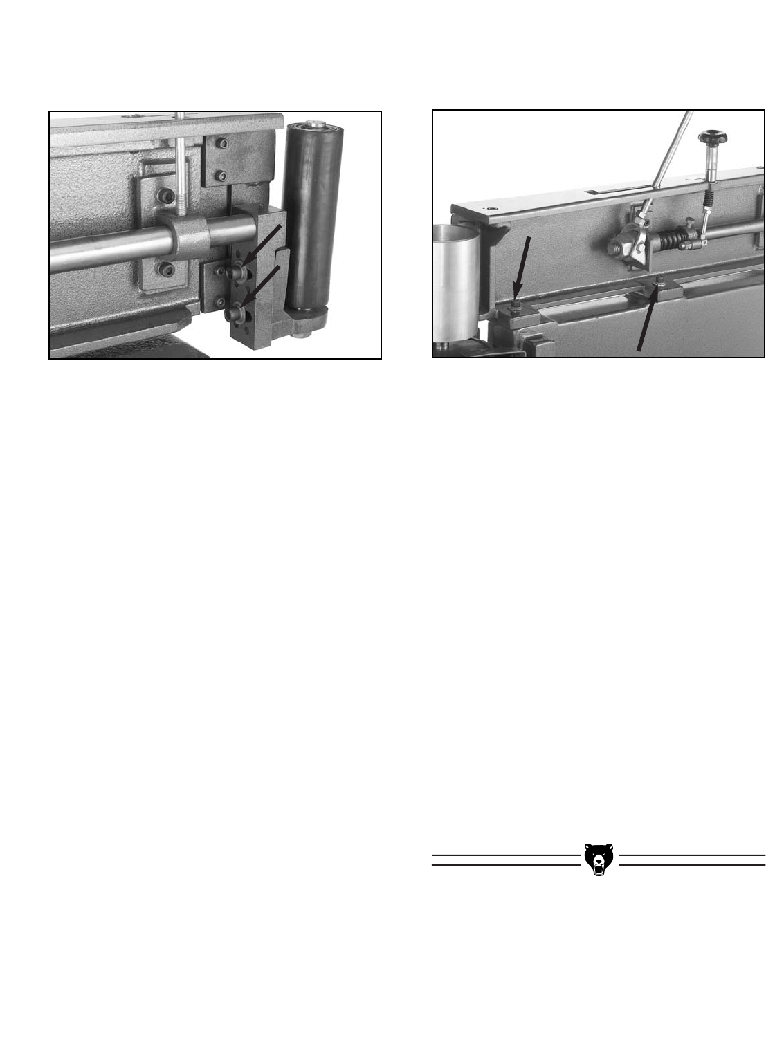
7. Tighten the two cap screws shown in Figure
40.
8. Replace and track the belt with the tracking
knob, so the side of the belt that is tracking
higher (if it is) is even with the top of the
graphite.
— If the lower side of the belt is less than 1⁄8"
away from the top of the graphite, then
you do not need to make further adjust-
ments for parallel tracking.
— If the lower side of the belt is still more
than 1⁄8" away from the top of the graphite,
estimate how much the belt moved from
when you originally checked it. Compare
this movement with how much you turned
the two setscrews in step 6, and then
repeat steps 4-7, but adjust the
setscrews discussed in step 6 the
amount that you estimate will fix the par-
allel tracking. Repeat as necessary until
the parallel tracking is correct.
Figure 39. Table removed w/attached supports.
Figure 40. Idler roller adjustment screws.
To adjust the parallel tracking of the sanding
belt:
1. Disconnect the sander from the power
source!
2. Remove the dust port.
3. Remove the table by removing the lock han-
dles, but keeping the L support brackets and
elevation plate attached to the table as
shown in Figure 39.
4. Remove the sanding belt.
5. Loosen the two cap screws (shown with
black arrows in Figure 40) approximately
half a turn, and notice the four setscrews
nearby (shown with white arrows in Figure
40)—these control the parallel tracking of the
sanding belt.
-28- G0512 Edge Sander
Platen-to-Rollers
Adjustments
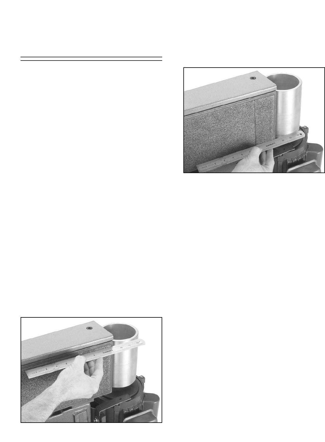
Figure 41. Checking top of platen-to-roller.
Figure 42. Checking bottom of platen-to-roller.
The platen can be adjusted forward or backward
in relation to the main and idler rollers. When the
platen is correctly adjusted, it should extend
beyond the rollers approximately 1⁄8". If the platen
extends beyond this, the belt will stretch and the
graphite pad will wear quicker.
Because the idler roller is attached to the platen,
it will need to be adjusted independently to com-
plete this procedure.
Also, if the main roller is not vertically parallel with
the platen, the motor will need to be adjusted on
the motor mount to complete this procedure.
Instructions for all three adjustments will be given
below. First, check the platen-to-roller relation-
ship to see if you need to make the adjustments.
To check the platen-to-main roller relation-
ship:
1. Disconnect the sander from the power
source!
2. Remove the sanding belt and dust port.
3. Place a straightedge across the TOP part of
the platen graphite and the main roller as
shown in Figure 41. Measure the gap, if
there is one, between the straightedge and
the main roller.
4. Now place the straightedge across the BOT-
TOM part of the platen graphite and the main
roller as shown in Figure 42. Measure the
gap, if there is one, between the straightedge
and the main roller.
5. Analyze the results of your check in steps 3-
4, using the criteria below:
—Correct Platen-to-Main Roller
Relationship: The distance between the
straightedge and the main roller is
approximately 1⁄8" at both the top and bot-
tom. No adjustments are necessary to
the platen position or the main roller posi-
tion.
—Platen Incorrect: The distances between
the straightedge and the main roller at
both the top and bottom are more or less
than 1⁄8", but the distances at both the top
and bottom are approximately the same.
The platen needs to be adjusted.
—Main Roller Incorrect: The distance
between the straightedge and the main
roller is different at the top than it is at the
bottom. The main roller needs to be
adjusted.
To check the platen-to-idler roller relation-
ship:
1. Follow steps 1–2 from the previous instruc-
tions.
G0512 Edge Sander -29-
4. Place a straightedge across the TOP part of
the platen graphite and the main roller, and
adjust the main roller so that it is even with
the platen graphite at both the top and bot-
tom of the roller. Note—You can also adjust
the motor approximately 1⁄8" behind the plat-
en and skip step 7, but this alternative may
be more more complicated.
5. Tighten the motor mount bolts carefully,
making sure not to move the motor from its
corrected position.
6. Recheck the main roller-to-platen alignment.
— If the alignment is correct, then it is adjust-
ed correctly. Proceed to step 7.
— If the alignment is incorrect, repeat steps
3-5.
7. Adjust the platen as described on the previ-
ous page.
8. Replace the sanding belt and dust port, and
retrack the sanding belt with the tracking
knob before resuming sanding operations.
To adjust the idler roller-to-platen relation-
ship:
1. Disconnect the sander from the power
source!
2. Remove the sanding belt.
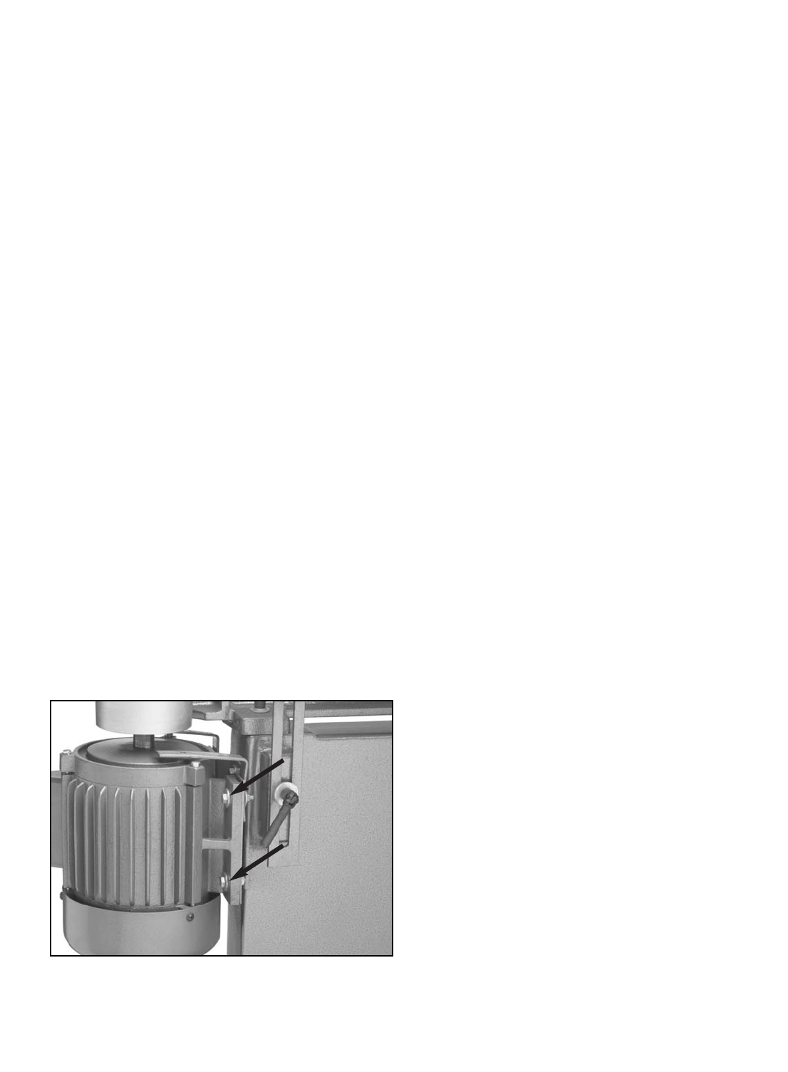
Figure 43. Two of the four motor mount bolts.
2. Place the straightedge across the TOP of the
platen graphite and the idler roller. Measure
the gap, if there is one, between the straight-
edge and the main roller.
3. Place the straightedge across the BOTTOM
of the platen graphite and the idler roller.
Measure the gap, if there is one, between the
straightedge and the main roller.
—Correct Platen-to-Idler Roller
Relationship: The distance between the
straightedge and the idler roller is approx-
imately 1⁄8" at both the top and bottom. No
adjustments are necessary to the idler
roller position.
—Idler Roller Incorrect: The distances
between the straightedge and the main
roller at both the top and bottom are more
or less than 1⁄8". Adjust the idler roller.
To adjust the main roller-to-platen relation-
ship:
1. Disconnect the sander from the power
source!
2. Remove the sanding belt and dust port.
3. Loosen the four motor mount bolts/nuts that
secure the motor to the motor bracket.
Figure 43 shows two of the four motor mount
bolts.
-30- G0512 Edge Sander
Figure 44. Idler roller adjustment cap screws.
4. Place a straightedge across the TOP part of
the platen graphite and in front of the idler
roller, and adjust the idler roller so that it is
approximately 1⁄8" away from the straight-
edge.
5. Place a straightedge across the BOTTOM
part of the platen graphite and in front of the
idler roller, and adjust the idler roller so that it
is approximately 1⁄8" away from the straight-
edge.
6. Check the adjustments made in steps 5-6,
and tighten the cap screws that you loosened
in step 3, making sure not to move the cor-
rected idler roller position during tightening.
7. Replace the sanding belt and dust port, and
retrack the sanding belt with the tracking
knob before resuming sanding operations.
The platen can also be adjusted, but this adjust-
ment should be done carefully because moving
the platen too far will make the sanding belt press
against the table.
To adjust the platen:
1. Disconnect the sander from the power
source!
2. Remove the sanding belt and dust port.
3. Loosen the two cap screws, shown in
Figure 44, approximately one full turn.
3. Loosen the two cap screws shown in Figure
45.
Figure 45. The two cap screws that secure the
platen for adjustments.
4. Place a straightedge across the platen
graphite and in front of the main roller.
5. Adjust the platen so the distance between
the straightedge and main roller is approxi-
mately 1⁄8".
6. Tighten both cap screws in an even manner
and recheck the distance between the plat-
en and the main roller to make sure that it
did not move when you tightened the cap
screws.
— If the platen did move, repeat steps 3-5
until it is positioned properly.
— If the platen did not move, then it is
adjusted correctly. Proceed to step 7.
7. Replace the sanding belt and dust port, and
retrack the sanding belt with the tracking
knob before resuming sanding operations.
G0512 Edge Sander -31-
The following pages contain troubleshooting, the
wiring diagram, general machine data, parts dia-
grams, parts lists and Warranty/Return information
for your Model G0512.
If you need parts or help in assembling your
machine, or if you need operational information,
call the Grizzly Service Department. Trained ser-
vice technicians will be glad to help you.
If you have any comments regarding this manual,
please write to Grizzly at the address below:
Grizzly Industrial, Inc.
C/OTechnical Documentation
P.O. Box 2069
Bellingham, WA 98227-2069
We recommend you keep a copy of our current
catalog for complete information regarding
Grizzly's warranty and return policy. If you need
additional technical information relating to this
machine, or if you need general assistance or
replacement parts, please contact the Service
Department at the location listed below.
Grizzly Industrial, Inc.
1203 Lycoming Mall Circle
Muncy, PA 17756
Phone: (570) 546-9663
Fax: (800) 438-5901
E-Mail: techsupport@grizzly.com
Web Site: http://www.grizzly.com.
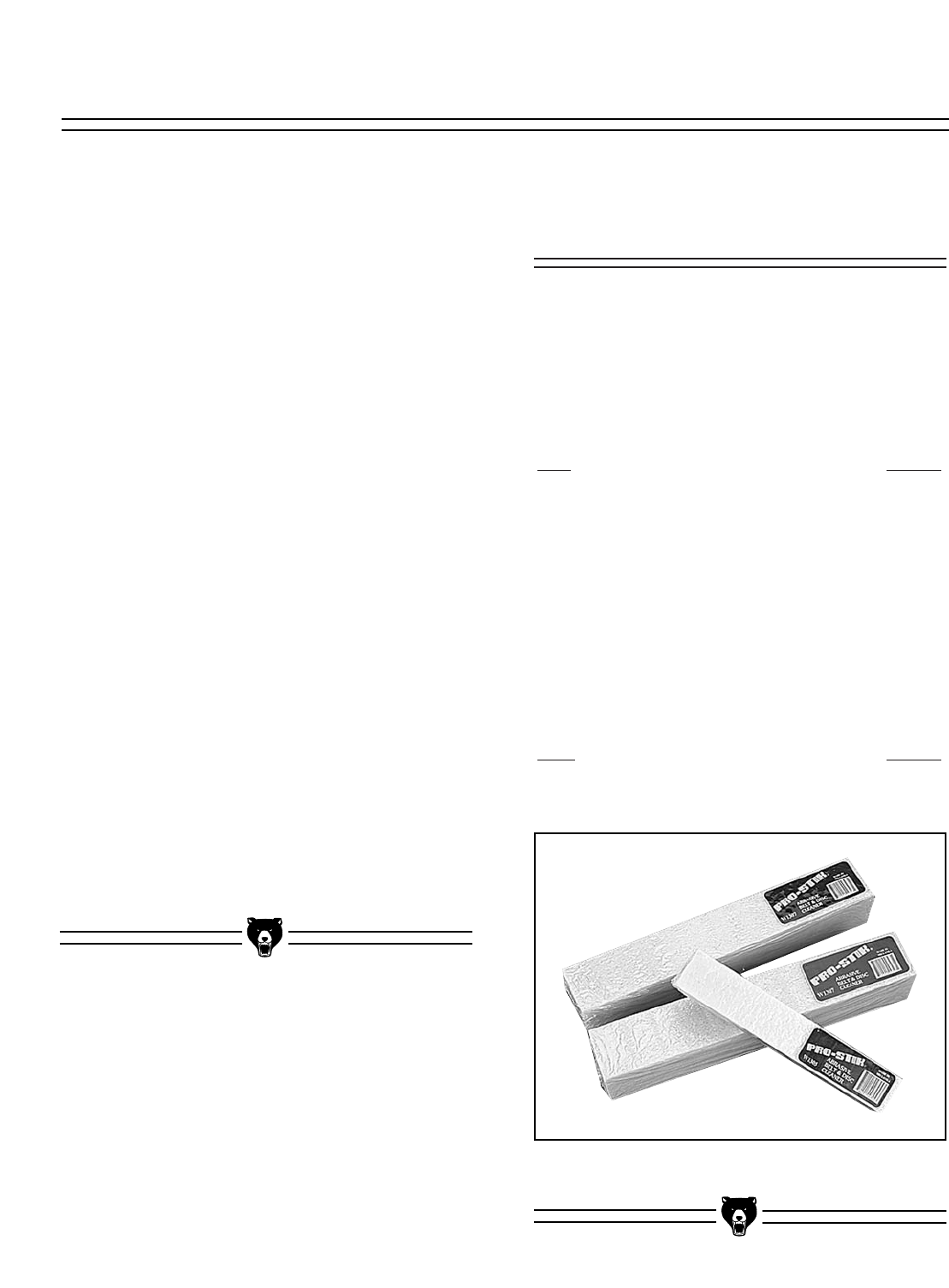
Figure 46. PRO-STIK®Abrasive Belt Cleaners.
To order any of the aftermarket accessories
below, call our customer service line 24 hours a
day at 1-800-523-4777.
Extra 6" x 80" Belts
Grit Model
60..............................................................G1532
80..............................................................G4287
100............................................................G1533
120............................................................G4288
150............................................................G1534
180............................................................G4289
220............................................................G4290
PRO-STICK®Abrasive Belt Cleaners
Extend the life of your belts!
Size Model
11⁄2" X 11⁄2" X 81⁄2" ....................................G1511
2" X 2" X 12" ............................................G1512
Aftermarket
Accessories
SECTION 9: REFERENCE INFO

-32- G0512 Edge Sander
Design Type ........................................................................ Expanded Table, Floor Model
Overall Dimensions and Specifications:
Table Size ....................................................................................................24" x 421⁄4"
Overall Height (With Handle Up) ..........................................................................483⁄4"
Table Height ......................................................................................................33"-39"
Length....................................................................................................................521⁄2"
Width ........................................................................................................................24"
Platen Size......................................................................61⁄4'' x 311⁄2", Graphite Coated
Belt Size ............................................................................................................6" x 80"
Belt Speed ....................................................................................................1800 FPM
Shipping Weight ................................................................................................250 lbs.
Machine Weight ................................................................................................235 lbs.
Footprint ......................................................................................................141⁄2" x 32"
Construction:
Base ............................................................................Welded Steel - Powder Coated
Table ............................................................................Composite w/ Formica Surface
Rubber Idler Roller..............................................................Shielded Ball Bearing, 21⁄8"
Drive Roller ..................................................................................Cast Aluminum, 41⁄2"
Motor:
Type ............................................................................TEFC Capacitor Start Induction
Horsepower ........................................................................................................11⁄2HP
Phase / Voltage ...................................... Single Phase ⁄ 110V ⁄ 220V; Prewired 220V
Amps ..................................................................................................................20 ⁄ 10
Cycle and RPM ............................................................................60 Hertz ⁄ 1725 RPM
Switch ..........................................................Toggle Safety Switch w/ Safety Lock Tab
Power Transfer ..........................................................................................Direct Drive
Bearings ..............................................................Shielded & Lubricated Ball Bearings
Features:
............................................................................................Extended Sanding Surface
......................................................................................................................Work Stop
....................................................................................................................4" Dust Port
........................................................................................................Quick Belt Release
..........................................................................Belt Tracking and Tension Adjustment
............................................................................Handwheel Table Height Adjustment
....................................................................................................Powder Coated Stand
Specifications, while deemed accurate, are not guaranteed.
Customer Service #: (570) 546-9663 • To Order Call: (800) 523-4777 • Fax #: (800) 438-5901
GRIZZLY MODEL G0512 HEAVY-DUTY EDGE SANDER
MACHINE DATA
SHEET
G0512 Edge Sander -33-
114
116
74
17
69
108
20A
14
15
20
78
52
65
78
64
66
113
58
61
59
72 74
21
10
115
24
12
21A
94
10
11
9
33
94
87
90
23A
54
36
39
27
92
83
29
35
28
30
22
81
5
25
3
1
4A
4B
3
4A
4B
74
72
80
73
2
23B
42
5
24
43
31
40
37
41 32
73
53
55
56
52 94
71
17
80
78 70
75
86
6
77
7
8
79
46
51B
51A
51A 52
52
78
78
78A
49
74
74
95
109 109A
99 50
50
50
50 50
111
78
51D
51D
51E 51C
17
26
34
112
110
94
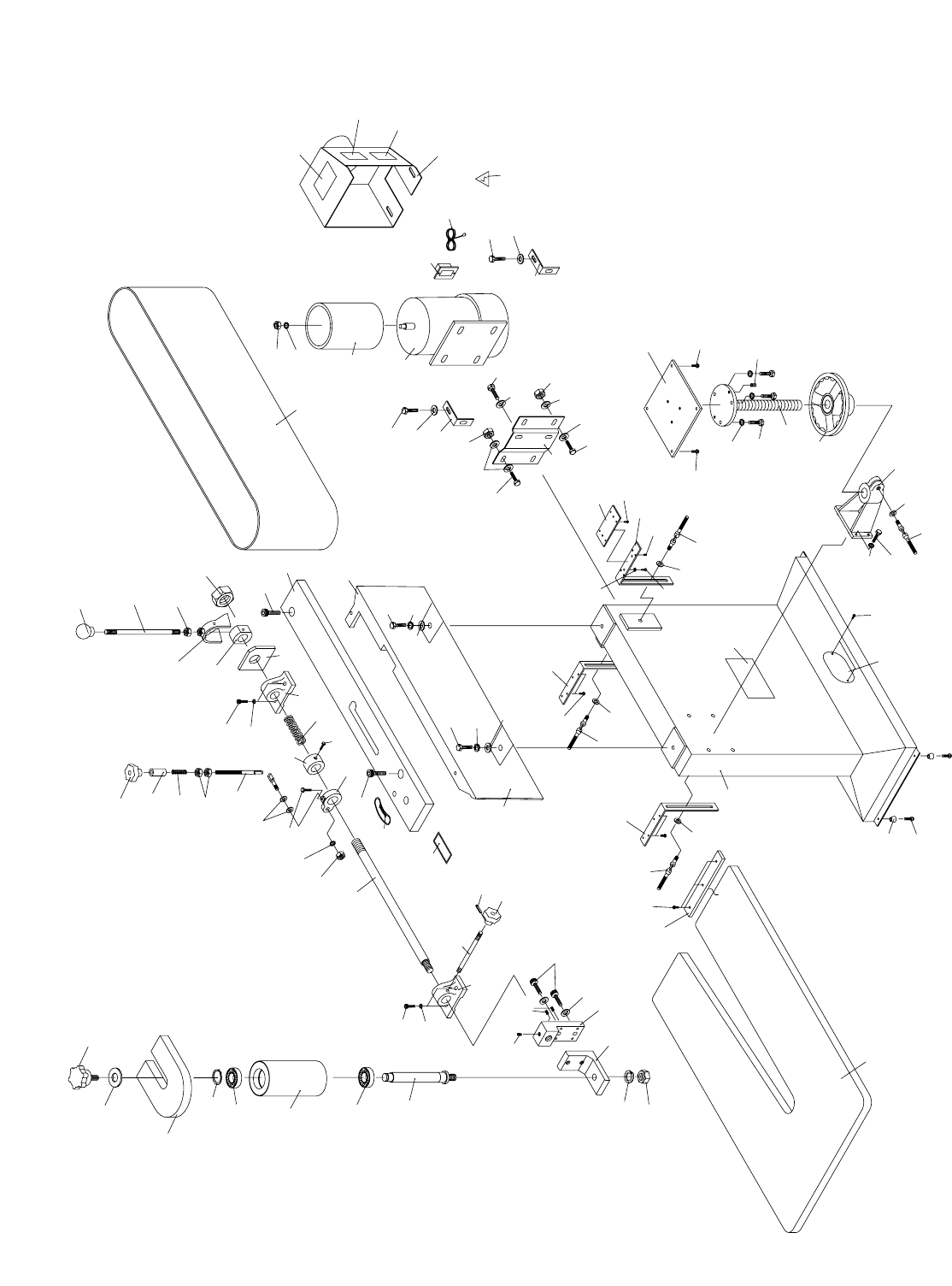
Parts Breakdown and List

-34- G0512 Edge Sander
1 P0512001 PLATEN
2 P0512002 PLATEN COVER
3 PB16 HEX BOLT 3⁄8"-16 X 11⁄2"
4A PLW06M LOCK WASHER 10MM
4B PW02 FLAT WASHER 3⁄8"
5 PSB14 CAP SCREW 3⁄8"-16 X 1"
6 P0512006 DRIVER ROLLER
7 PN09 HEX NUT 5⁄8"-18
8 PLW10M LOCK WASHER 16MM
9 PR08M EXT RETAINING RING 19MM
10 P0512010 BALL BEARING R12-Z
11 P0512011 RUBBER IDLER ROLLER
12 P0512012 ROLLER AXLE
14 PLW10M LOCK WASHER 16MM
15 PN04 HEX NUT 5⁄8"-11
17 PB09 HEX BOLT 5⁄16"-18 X 1⁄2"
20 P0512020 ROLLER SUPPORT BRACKET
20A P0512020A ROLLER BLOCK BRACKET
21 PSS10 SET SCREW 1⁄4"-20 X 5⁄8"
21A P0512021A SPECIAL SCREW 1⁄4"-20 X 5⁄8"
22 P0512022 BELT ADJUST SHAFT
23A P0512023A ADJUST SHAFT SLIDE (A)
23B P0512023B ADJUST SHAFT SLIDE (B)
24 PSB03 CAP SCREW 5⁄16"-18 X 1
25 P0512025 SPRING
26 PB07 HEX BOLT 5⁄16"-18 X 3⁄4"
27 P0512027 ARM CONTROL CASTING
28 P0512028 SLEEVE
29 P0512029 CONTROL SHAFT
30 P0512030 SPRING
31 PN13 HEX NUT 1⁄2"-13
32 PN22 HEX NUT 1-8
33 P0512033 TILT KNOB 3⁄8"
34 PB21 HEX BOLT 3⁄8"-16 X 3⁄4"
35 PN08 HEX NUT 3⁄8"-16
36 P0512036 LOCK KNOB STUD 3⁄8" X 53⁄8"
37 P0512037 SWIVEL ASSEMBLY
39 P0512039 COLLAR
40 P0512040 LEVER
41 P0512041 SWIVEL ASSEMBLY
42 P0512042 PLATE
43 P0512043 HANDLE 1⁄2"
46 P0512046 TABLE
49 P0512049 PARTITION
50 PHTEK11 PHLP HD TAP SCREW #8 X 3⁄4"
51A P0512051A TABLE SUPP BRACKET (A)
51B P0512051B TABLE SUPP BRACKET (B)
51C P0512051C ADJUSTMENT PLATE
REF PART # DESCRIPTION
51D PSS02 SETSCREW 5⁄16"-18 X 3⁄8"
52 P0512052 SWIVEL HANDLE 3⁄8" X 11⁄4"
53 P0512053 LEAD SCREW
54 P0512054 KNOB 3⁄8"
55 PB32 HEX BOLT 5⁄16"-18 X 5⁄8"
56 P0512056 HAND WHEEL
58 P0512058 SPLIT CASTING
59 PB18 HEX BOLT 3⁄8"-16 X 1"
61 PLW06M LOCK WASHER 10MM
64 P0512064 STAND
65 PS22 PHLP HD SCR 10-24 X 5⁄8"
66 P0512066 RUBBER FOOT
69 P0512069 MOTOR BRACKET
70 PB18 HEX BOLT 3⁄8"-16 X 1"
71 P0512071 MOTOR 11⁄2HP
71-1 P0512071-1 MOTOR FAN COVER
71-2 P0512071-2 MOTOR FAN
71-3 P0512071-3 MOTOR WIRING CAP
71-4 PC400A CAPACITOR 400MFD 125VAC
71-5 P0512071-5 CAPACITOR COVER
72 PB12 HEX BOLT 5⁄16"-18 X 11⁄4"
73 PN02 HEX NUT 5⁄16"-18
74 PW07 FLAT WASHER 5⁄16"
75 G8988 SWITCH
77 G1532 SANDING BELT 6" X 80"
78 PW02 FLAT WASHER 3⁄8"
79 P0512079 DUST COLLECTION HOOD
80 P0512080 LEFT BRACKET
81 P0512081 TRACKING ARROW LABEL
83 P0512083 TRACKING LOCK LABEL
86 PWRCRD220L POWER CORD 2 POLE/3 WIRE
87 PN08 HEX NUT 3⁄8"-16
90 PRP37M ROLL PIN 3 X 14
92 P0512092 GRAPHITE PAD
94 PLW04M LOCK WASHER 8MM
95 P0512095 MACHINE ID LABEL
99 P0512099 BACK STOP
108 PSB26 CAP SCREW 3⁄8"-16 X 11⁄2"
109 G8588 GRIZZLY LOGO PLATE
109A PHTEK10 TAP SCREW #8 X 5/8"
110 PLABEL-12 READ MANUAL LABEL
111 PLABEL-14 ELECTRICITY LABEL
112 PLABEL-11 SAFETY GLASSES LABEL
113 PLABEL-13 UNPLUG SANDER LABEL
114 P0512114 SMALL STAR KNOB
115 P0512115 IDLER ROLLER COVER
116 PW06 FLAT WASHER 1⁄4"
REF PART # DESCRIPTION

G0512 Edge Sander -35-
SYMPTOM
Motor will not start.
Motor will not start; fuses or
circuit breakers blow.
Motor overheats.
Motor stalls (resulting in
blown fuses or tripped cir-
cuit).
Machine slows when oper-
ating.
Loud, repetitious noise com-
ing from machine.
Machine vibrates excessive-
ly.
POSSIBLE CAUSE
1. Low voltage.
2. Open circuit in motor or loose connec-
tions.
1. Short circuit in line cord or plug.
2. Short circuit in motor or loose connec-
tions.
3. Incorrect fuses or circuit breakers in
power line.
1. Motor overloaded.
2. Air circulation through the motor
restricted.
1. Short circuit in motor or loose connec-
tions.
2. Low voltage.
3. Incorrect fuses or circuit breakers in
power line.
4. Motor overloaded.
1. Applying too much pressure to work-
piece.
2. Undersized circuit or using ext cord.
1. Pulley setscrews or keys are missing or
loose.
2. Motor fan is hitting the cover.
1. Stand not stable on floor.
2. Incorrect motor mounting.
3. Incorrect sanding belt tension.
4. Weak or broken tension spring.
5. Idler roller is too loose.
6. Broken/defective sanding belt.
CORRECTIVE ACTION
1. Check power line for proper voltage.
2. Inspect all lead connections on motor for loose or open connec-
tions.
1. Inspect cord or plug for damaged insulation and shorted wires.
2. Inspect all connections on motor for loose or shorted terminals
or worn insulation.
3. Install correct fuses or circuit breakers.
1. Reduce load on motor.
2. Clean out motor to provide normal air circulation.
1. Inspect connections on motor for loose or shorted terminals or
worn insulation.
2 Correct the low voltage conditions.
3. Install correct fuses or circuit breakers.
4. Reduce load on motor.
1. Sand with less pressure—let the movement of the belt do the
work.
2. Make sure circuit wires are proper gauge & don’t use ext cords!
1. Inspect keys and setscrews. Replace or tighten if necessary.
2. Tighten fan or shim cover.
1. Secure stand to floor, reposition to level surface, or shim stand.
2. Check/adjust motor mounting.
3. Make sure tension lever is in tensioning position. Follow belt ten-
sioning instructions in this manual.
4. Replace spring.
5. Adjust idler roller.
6. Replace sanding belt.
Troubleshooting Machine
Disconnect power to the
machine when perform-
ing any maintenance or
repairs. Failure to do this
may result in serious
personal injury.

-36- G0512 Edge Sander
SYMPTOM
Deep sanding grooves or
marks in workpiece.
Grains easily rub off the
belt.
Glazed sanding belt.
Burning marks on work-
piece.
Sanding belt clogs quickly
or burns.
Workpiece frequently gets
pulled out of your hand.
Sanding belt comes off dur-
ing operation.
POSSIBLE CAUSE
1. Sanding belt grit too coarse for the
desired finish.
2. Workpiece is being sanded across the
grain.
3. Too much sanding force on workpiece.
4. Workpiece held still against the belt.
1. Sanding belt has been stored in an
incorrect environment.
2. Sanding belt has been folded or
smashed.
1. Sanding wet stock.
2. Sanding stock with high residue.
1. Using too fine of sanding belt grit.
2. Using too much pressure against belt.
3. Work held still for too long.
1. Using too much pressure against belt.
2. Sanding softwood.
1. Not supporting the workpiece against
the stop.
2. Starting the workpiece on a leading cor-
ner.
1. Tracking out of adjustment.
CORRECTIVE ACTION
1. Use a finer grit sanding belt.
2. Sand with the grain.
3. Reduce pressure on workpiece while sanding.
4. Keep workpiece moving while sanding on the belt.
1. Store sanding belt away from extremely dry or hot temperatures.
2. Hang sanding belt or store unfolded and unstacked.
1. Dry stock properly before sanding.
2. Use different stock. Or, accept the characteristics of the stock
and plan on cleaning/replacing belts frequently.
1. Use a coarser grit sanding belt.
2. Reduce pressure on workpiece while sanding.
3. Do not keep workpiece in one place for too long.
1. Reduce pressure on workpiece while sanding.
2. Use different stock. Or, accept the characteristics of the stock
and plan on cleaning/replacing belts frequently.
1. Use back stop to support workpiece.
2. Start workpiece on a trailing corner.
1. Track the belt as described in Section: 5 Set Up.
Troubleshooting Sanding
Disconnect power to the
machine when perform-
ing any maintenance or
repairs. Failure to do this
may result in serious
personal injury.
G0512 Edge Sander -37-
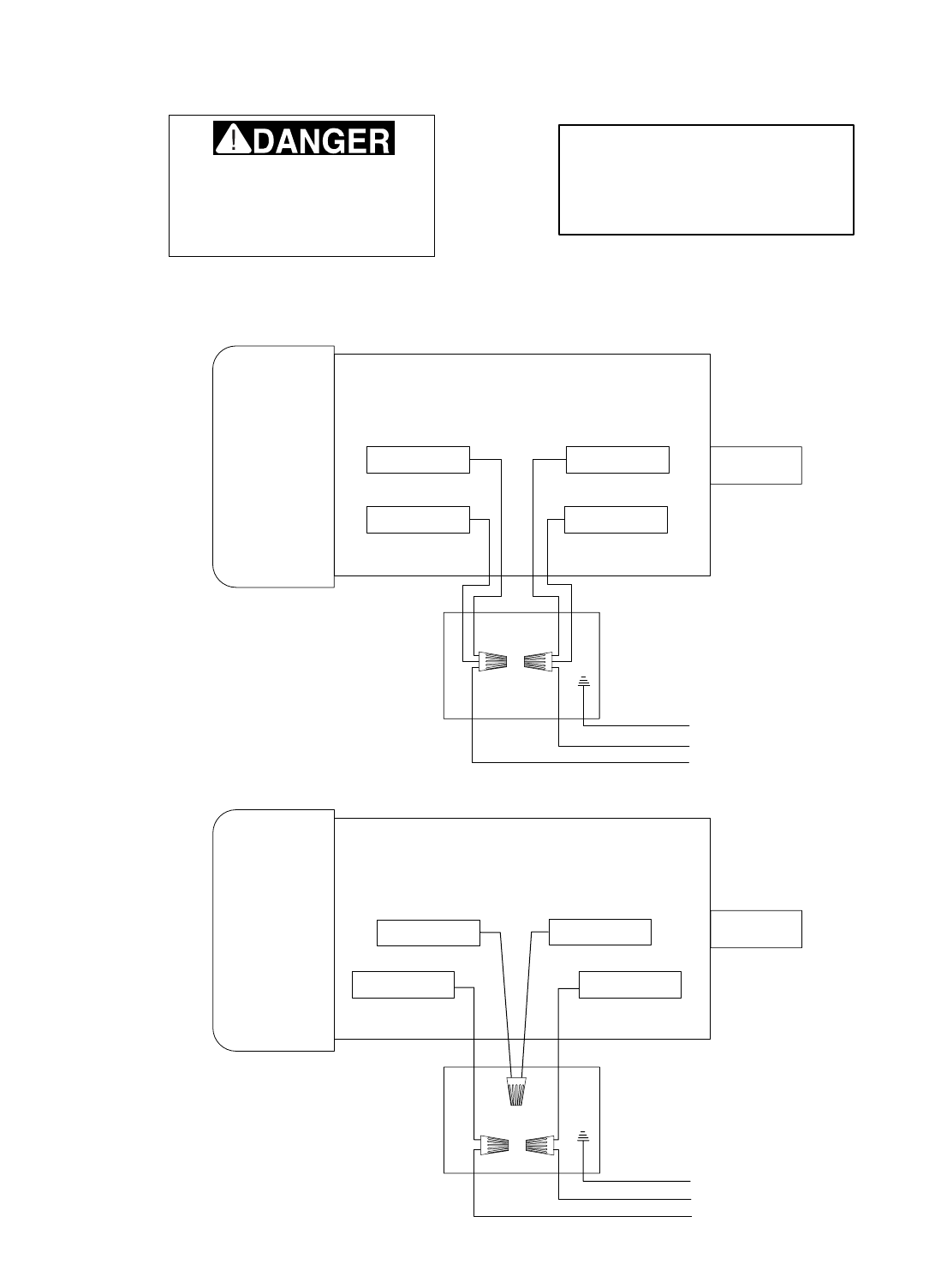
WHITE RED
BLACK YELLOW
MOTOR WIRES
110 VOLT
GREEN (GROUND)
TO 110 VOLT
POWER SUPPLY
RED WHITE
BLACK YELLOW
MOTOR WIRES
220VOLT
GREEN (GROUND)
TO 220 VOLT
POWER SUPPLY
NOTE: THE WIRES FROM THE
POWER SUPPLY, EXCEPT THE
GREEN GROUND WIRE, ARE
INTERCHANGABLE, THEREFORE
COLORS ARE NOT SPECIFIED.
Disconnect power from machine
before performing any electrical
service. Failure to do this will
result in a shock hazard, leading
to injury or death.
Copyright © May, 2003. Grizzly Industrial, Inc.Ł
Model G0512
G0512 Wiring Diagram

-38- G0512 Edge Sander
Grizzly Industrial, Inc. warrants every product it sells for a period of 1 year to the original purchaser from
the date of purchase. This warranty does not apply to defects due directly or indirectly to misuse, abuse,
negligence, accidents, repairs or alterations or lack of maintenance. This is Grizzly’s sole written warranty
and any and all warranties that may be implied by law, including any merchantability or fitness, for any par-
ticular purpose, are hereby limited to the duration of this written warranty. We do not warrant or represent
that the merchandise complies with the provisions of any law or acts unless the manufacturer so warrants.
In no event shall Grizzly’s liability under this warranty exceed the purchase price paid for the product and
any legal actions brought against Grizzly shall be tried in the State of Washington, County of Whatcom.
We shall in no event be liable for death, injuries to persons or property or for incidental, contingent, spe-
cial, or consequential damages arising from the use of our products.
To take advantage of this warranty, contact us by mail or phone and give us all the details. We will then
issue you a “Return Number,’’ which must be clearly posted on the outside as well as the inside of the car-
ton. We will not accept any item back without this number. Proof of purchase must accompany the mer-
chandise.
The manufacturers reserve the right to change specifications at any time because they constantly strive to
achieve better quality equipment. We make every effort to ensure that our products meet high quality and
durability standards and we hope you never need to use this warranty.
Please feel free to write or call us if you have any questions about the machine or the manual.
Thank you again for your business and continued support. We hope to serve you again soon.
Warranty and Returns

CUT ALONG DOTTED LINE
9. How many of your woodworking machines are Grizzly? _____________
10. Which benchtop tools do you own? Check all that apply.
___1" x 42" Belt Sander ___6" - Edge Grinder
___5" - Edge Drill Press ___Mini Lathe
___Edge Table Saw ___10" - 12" Thickness Planer
___Edge - 10" Bandsaw ___Scroll Saw
___Disc/Belt Sander ___Spindle/Belt Sander
___Mini Jointer
___Other__________________________________________________
11. How many of the machines checked above are Grizzly? ____________
12. Which portable/hand held power tools do you own? Check all that apply.
___Belt Sander ___Orbital Sander
___Biscuit Joiner ___Palm Sander
___Circular Saw ___Portable Planer
___Detail Sander ___Saber Saw
___Drill/Driver ___Reciprocating Saw
___Miter Saw ___Router
___Other__________________________________________________
13. What machines/supplies would you like Grizzly Industrial to carry?
__________________________________________________________
__________________________________________________________
14. What new accessories would you like Grizzly Industrial to carry?
__________________________________________________________
__________________________________________________________
15. What other companies do you purchase your tools and supplies from?
__________________________________________________________
__________________________________________________________
16. Do you think your purchase represents good value?
___Yes ___No
17. Would you recommend Grizzly Industrial to a friend?
___Yes ___No
18. Would you allow us to use your name as a reference for Grizzly customers
in your area? Note: We never use names more than three times.
___Yes ___No
19. Comments:_________________________________________________
__________________________________________________________
__________________________________________________________
__________________________________________________________
__________________________________________________________
1. How did you learn about us?
___Advertisement ___Friend
___Catalog ___Card Deck
___World Wide Web
___Other__________________________________________________
2. Which of the following magazines do you subscribe to.
___American Woodworker ___Practical Homeowner
___Cabinetmaker ___Shop Notes
___Family Handyman ___Today’s Homeowner
___Fine Homebuilding ___WOOD
___Fine Woodworking ___Wooden Boat
___Home Handyman ___Woodshop News
___Journal of Light Construction ___Woodsmith
___Old House Journal ___Woodwork
___Popular Mechanics ___Woodworker
___Popular Science ___Woodworker’s Journal
___Popular Woodworking ___Workbench
___Other__________________________________________________
3. Which of the following woodworking/remodeling shows do you watch?
___Backyard America ___The New Yankee Workshop
___Home Time ___This Old House
___The American Woodworker ___Woodwright’s Shop
___Other__________________________________________________
4. What is your annual household income?
___$20,000-$29,999 ___$60,000-$69,999
___$30,000-$39,999 ___$70,000-$79,999
___$40,000-$49,999 ___$80,000-$89,999
___$50,000-$59,999 ___$90,000 +
5. What is your age group?
___20-29 ___50-59
___30-39 ___60-69
___40-49 ___70 +
6. How long have you been a woodworker?
___0 - 2 Years ___8 - 20 Years
___2 - 8 Years ___20+ Years
7. How would you rank your woodworking skills?
___Simple ___Advanced
___Intermediate ___Master Craftsman
8. What stationary woodworking tools do you own? Check all that apply.
___Air Compressor ___Panel Saw
___Band Saw ___Planer
___Drill Press ___Power Feeder
___Drum Sander ___Radial Arm Saw
___Dust Collector ___Shaper
___Horizontal Boring Machine ___Spindle Sander
___Jointer ___Table Saw
___Lathe ___Vacuum Veneer Press
___Mortiser ___Wide Belt Sander
___Other__________________________________________________
Name ____________________________________________________________________________________
Street ____________________________________________________________________________________
City ______________________________________________________________State________Zip_________
Phone Number_______________________E-Mail_______________________FAX________________________
MODEL # G0512 Edge Sander Serial # _________________________ Order #______________________
The following information is given on a voluntary basis. It will be used for marketing purposes to help us develop better products and services. Of
course, all information is strictly confidential.
WARRANTY CARD

FOLD ALONG DOTTED LINE
FOLD ALONG DOTTED LINE
GRIZZLY INDUSTRIAL, INC.
P.O. BOX 2069
BELLINGHAM, WA 98227-2069
Place
Stamp
Here
TAPE ALONG EDGES--PLEASE DO NOT STAPLE
Name_______________________________
Street_______________________________
City______________State______Zip______
Send a Grizzly Catalog to a friend:


"UY$IRECTAND3AVEWITH'RIZZLY
®
n4RUSTED0ROVENANDA'REAT6ALUE
/2
s3%#52%/2$%2).'
s/2$%233()00%$7)4().(/523
s%-!),2%30/.3%7)4()./.%(/52
6ISIT/UR7EBSITE4ODAY!ND$ISCOVER7HY
'RIZZLY
§
)S4HE)NDUSTRY,EADER
#ALL4ODAY&OR!
&2%%
&ULL#OLOR#ATALOG
