Grizzly G5963 Manual Doc User To The 31031a63 13f7 4d6a Be0c 137fa9f5d0d6
User Manual: Grizzly G5963 to the manual
Open the PDF directly: View PDF ![]() .
.
Page Count: 30

6" x 12" SURFACE GRINDER
MODEL G5963
INSTRUCTION MANUAL
COPYRIGHT ©2000 BY GRIZZLY INDUSTRIAL, INC.
WARNING: NO PORTION OF THIS MANUAL MAY BE REPRODUCED IN ANY SHAPE
OR FORM WITHOUT THE WRITTEN APPROVAL OF GRIZZLY INDUSTRIAL, INC.
MARCH, 2000 PRINTED IN CHINA


G5963 Surface Grinder -1-
Table Of Contents PAGE
1. SAFETY
SAFETY INSTRUCTIONS FOR POWER TOOLS ................................................2-3
ADDITIONAL SAFETY INSTRUCTIONS FOR SURFACE GRINDERS ..................4
2. CIRCUIT REQUIREMENTS
110V OPERATION ....................................................................................................5
220V OPERATION ....................................................................................................5
GROUNDING ............................................................................................................6
EXTENSION CORDS ................................................................................................6
CHECK MOTOR ROTATION ....................................................................................6
3. INTRODUCTION
COMMENTARY ........................................................................................................7
UNPACKING..............................................................................................................8
PARTS INVENTORY................................................................................................8
CLEAN UP ................................................................................................................9
SITE CONSIDERATIONS ........................................................................................9
4. ASSEMBLY
LIFTING THE GRINDER ........................................................................................10
MOUNTING ON STAND..........................................................................................10
TABLE AND HANDWHEEL ....................................................................................11
GUARD ....................................................................................................................11
HANDWHEEL HANDLES........................................................................................11
5. OPERATIONS
OVERVIEW..............................................................................................................12
WHEEL SELECTION ..............................................................................................13
WHEEL MOUNTING ..........................................................................................13-14
WHEEL BALANCING ..............................................................................................14
WHEEL DRESSING ................................................................................................15
OIL PUMP................................................................................................................16
TYPICAL OPERATION............................................................................................16
ACCESSORIES ......................................................................................................17
TEST RUN ..............................................................................................................17
6. MAINTENANCE
GENERAL................................................................................................................18
TABLE......................................................................................................................18
GRINDING WHEELS ..............................................................................................18
LUBRICATION ........................................................................................................18
7. CLOSURE......................................................................................................................19
MACHINE DATA ......................................................................................................................20
TROUBLESHOOTING..............................................................................................................21
WIRING DIAGRAM ..................................................................................................................22
PARTS BREAKDOWN AND PARTS LISTS ......................................................................23-25
WARRANTY AND RETURNS ..................................................................................................26
-2- G5963 Surface Grinder
Safety Instructions For Power Tools
SECTION 1: SAFETY
5. KEEP CHILDREN AND VISITORS AWAY.
All children and visitors should be kept a
safe distance from work area.
6. MAKE WORK SHOP CHILD PROOF with
padlocks, master switches, or by removing
starter keys.
7. DON’T FORCE TOOL. It will do the job
better and safer at the rate for which it was
designed.
8. USE RIGHT TOOL. Don’t force tool or
attachment to do a job for which it was not
designed.
1. KEEP GUARDS IN PLACE and in working
order.
2. REMOVE ADJUSTING KEYS AND
WRENCHES. Form habit of checking to
see that keys and adjusting wrenches are
removed from tool before turning on.
3. KEEP WORK AREA CLEAN. Cluttered
areas and benches invite accidents.
4. DON’T USE IN DANGEROUS ENVIRON-
MENT. Don’t use power tools in damp or
wet locations, or where any flammable or
noxious fumes may exist. Keep work area
well lighted.
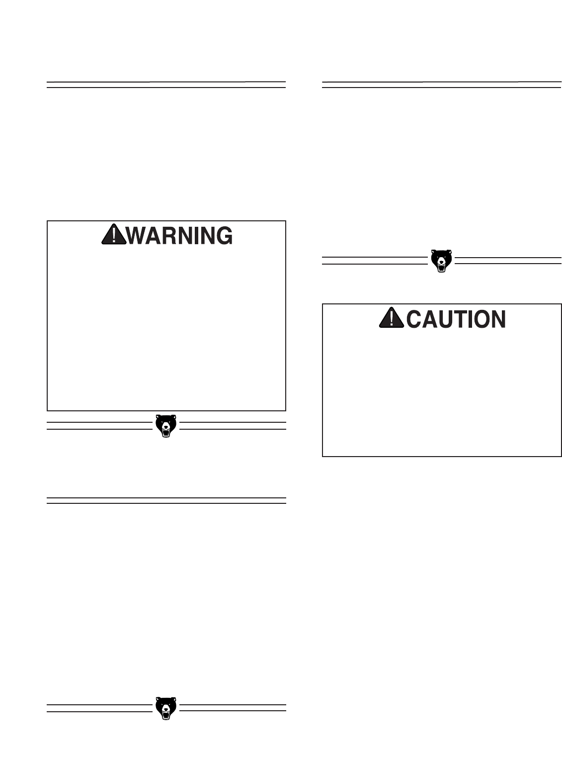
For Your Own Safety Read Instruction Manual
Before Operating This Equipment
Indicates an imminently hazardous situation which, if not avoided,
WILL result in death or serious injury.
Indicates a potentially hazardous situation which, if not avoided,
COULD result in death or serious injury.
Indicates a potentially hazardous situation which, if not avoided,
MAY result in minor or moderate injury. It may also be used to
alert against unsafe practices.
This symbol is used to alert the user to useful information about
proper operation of the equipment.
The purpose of safety symbols is to attract your attention to possible hazardous conditions. This man-
ual uses a series of symbols and signal words which are intended to convey the level of importance of
the safety messages. The progression of symbols is described below. Remember that safety messages
by themselves do not eliminate danger and are not a substitute for proper accident prevention mea-
sures.
NOTICE
G5963 Surface Grinder -3-
9. USE PROPER EXTENSION CORD. Make
sure your extension cord is in good condi-
tion. Conductor size should be in accor-
dance with the chart below. The amperage
rating should be listed on the motor or tool
nameplate. An undersized cord will cause a
drop in line voltage resulting in loss of
power and overheating. Your extension
cord must also contain a ground wire and
plug pin. Always repair or replace exten-
sion cords if they become damaged.
Minimum Gauge for Extension Cords
10. WEAR PROPER APPAREL. Do not wear
loose clothing, gloves, neckties, rings,
bracelets, or other jewelry which may get
caught in moving parts. Non-slip footwear
is recommended. Wear protective hair cov-
ering to contain long hair.
11. ALWAYS USE SAFETY GLASSES. Also
use face or dust mask if cutting operation is
dusty. Everyday eyeglasses only have
impact resistant lenses, they are NOT safe-
ty glasses.
12. SECURE WORK. Use clamps or a vise to
hold work when practical. It’s safer than
using your hand and frees both hands to
operate tool.
LENGTH
AMP RATING 25ft 50ft 100ft
0-6 18 16 16
7-10 18 16 14
11-12 16 16 14
13-16 14 12 12
17-20 12 12 10
21-30 10 10 No
Safety Instructions For Power Tools
13. DON’T OVERREACH. Keep proper footing
and balance at all times.
14. MAINTAIN TOOLS WITH CARE. Keep
tools sharp and clean for best and safest
performance. Follow instructions for lubri-
cating and changing accessories.
15. DISCONNECT TOOLS before servicing
and changing accessories, such as blades,
bits, cutters, and the like.
16. REDUCE THE RISK OF UNINTENTIONAL
STARTING. Make sure switch is in off
position before plugging in.
17. USE RECOMMENDED ACCESSORIES.
Consult the owner’s manual for recom-
mended accessories. The use of improper
accessories may cause risk of injury.
18. CHECK DAMAGED PARTS. Before fur-
ther use of the tool, a guard or other part
that is damaged should be carefully
checked to determine that it will operate
properly and perform its intended function.
Check for alignment of moving parts, bind-
ing of moving parts, breakage of parts,
mounting, and any other conditions that
may affect its operation. A guard or other
part that is damaged should be properly
repaired or replaced.
19. NEVER LEAVE TOOL RUNNING UNAT-
TENDED. TURN POWER OFF. Don’t
leave tool until it comes to a complete stop.
-4- G5963 Surface Grinder
Additional Safety Instructions For Surface Grinders
No list of safety guidelines can be complete.
Every shop environment is different. Always
consider safety first, as it applies to your indi-
vidual working conditions. Use this and other
machinery with caution and respect. Failure to
do so could result in serious personal injury,
damage to equipment or poor work results.
Like all power tools, there is danger associat-
ed with the Model G5963 Surface Grinder. Use
the tool with respect and caution to lessen the
possibility of mechanical damage or operator
injury. If normal safety precautions are over-
looked or ignored, serious personal injury may
occur.
1. Ensure that the machine sits firmly on the
floor before use. Any “wobbles” must be
corrected by shimming or blocking before
operation.
2. This machine is not designed to process
any other material except metals.
3. Never position fingers or hands directly
between the grinding wheel and the table.
4. Do not operate surface grinder with
cracked or damaged grinding wheels.
5. Always use extreme care in handling grind-
ing wheels during installation. Always “ring
check” the wheel to determine possible
damage.
6. Ensure that the surface grinder is properly
adjusted before using.
7. Never load or unload the workpiece while
the grinding wheel is rotating or the table is
moving.
8. If using coolants for grinding, always read
and understand the user information listed
on the coolant container. Some coolants
used for machining may be hazardous to
your health if not used and stored properly.
9. This manual is intended to familiarize you
with this grinding machine. It is not, nor
was it ever intended to be, a comprehen-
sive training manual.
Operation of this equipment has the potential
to propel debris into the air which can cause
eye injury. Always wear safety glasses or gog-
gles when operating equipment. Everyday
glasses or reading glasses only have impact
resistant lenses, they are not safety glasses.
Be certain the safety glasses you wear meet
the appropriate standards of the American
National Standards Institute (ANSI).
G5963 Surface Grinder -5-
SECTION 2: CIRCUIT REQUIREMENTS
110V Operation
The motor supplied with the G5963 can be oper-
ated at either 110V or 220V. The motor comes
prewired for 110V. If you wish to operate at 220V,
refer to the section at right.
Under normal use, the motor draws approximate-
ly 7.4 amps @ 110V. We recommend a 15 amp
circuit breaker for 110V operation. This should be
satisfactory for normal use, while providing
enough protection against motor damage caused
by power surges.
Grizzly recommends that the circuit you use
should be dedicated, (i.e., the G5963 should pro-
vide the only draw from that circuit). If frequent
circuit failures occur when using the Surface
Grinder, contact our Service Department or your
local electrical contractor.
220V Operation
The G5963 Surface Grinder motor can be rewired
to operate at 220V. Refer to the wiring diagram
supplied with this manual. If converting to operate
at 220V, the 110V plug must be replaced with a
220V plug. Plugs and receptacles can be pur-
chased at your local hardware store or home cen-
ter. The type of plug you choose will depend upon
the type of 220V outlet used in your installation.
See Figure 2 for a typical plug and outlet. This
plug must be rated for at least 15 amp draw.
It is not necessary to change the switch supplied
with the G5963 for 220V operation.
Under normal 220V use, the motor draws approx-
imately 3.7 amps. We recommend a 10 amp cir-
cuit breaker or a 10 amp slow-blow fuse.
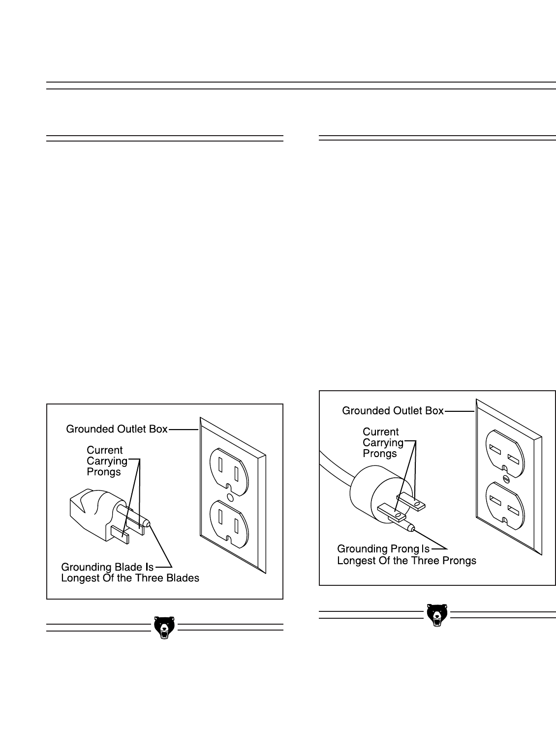
Figure 1. Typical 110V plug and outlet.
Figure 2. Typical 220V plug and outlet.
-6- G5963 Surface Grinder
We do not recommend the use of extension
cords on 220V equipment. It is much better to
arrange the placement of your equipment and the
installed wiring to eliminate the need for exten-
sion cords. Should it be necessary to use an
extension when operating at 110V, make sure the
cord is rated Hard Service (grade S) or better.
Refer to the chart in Section 1: Safety Instructions
to determine the minimum gauge for the exten-
sion cord. The extension cord must also contain
a ground wire and plug pin. Always repair or
replace extension cords when they become worn
or damaged.
Extension Cords
This equipment must be grounded. Please
ensure that this machine is continuously
grounded from the motor to the machine frame
and then to a known ground. Verify that any
existing electrical outlet and circuit you intend
to plug into is actually grounded. If it is not, it
will be necessary to run a separate 12 A.W.G.
copper grounding wire from the outlet to a
known ground. Under no circumstances should
the grounding pin from any three-pronged plug
be removed. Serious personal injury may
occur.
We have covered some basic electrical
requirements for the safe operation of your
Surface Grinder. These requirements are not
necessarily comprehensive. You must be sure
that your particular electrical configuration
complies with local and state codes. Ensure
compliance by checking with your local munic-
ipality or a licensed electrician.
Grounding
In the event of an electrical short, grounding
reduces the risk of electric shock by providing a
path of least resistance to disperse electric cur-
rent. This tool is equipped with a power cord hav-
ing an equipment-grounding conductor. See
Figure 1 and 2. The outlet must be properly
installed and grounded in accordance with all
local codes and ordinances.
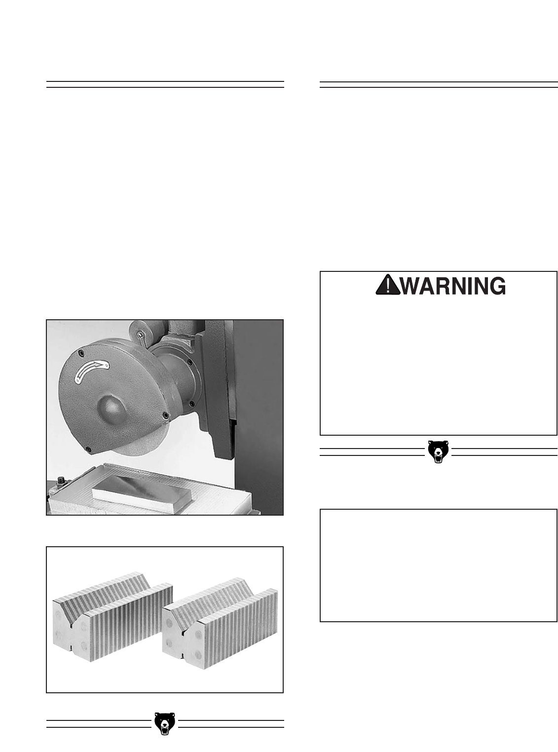
Check Motor Rotation
After the machine is assembled and properly
connected to electrical power, test the motor rota-
tion. Cycle the machine on and observe the rota-
tion of the grinding wheel. Make sure it rotates in
the direction indicated by the arrow on the wheel
guard. If it does not, the wiring may not be prop-
erly connected at the motor. Disconnect from the
power source, and check that the motor wiring
agrees with the wiring diagram provided in this
manual. Make necessary adjustments, close the
motor cover, reconnect to power, and test again.
G5963 Surface Grinder -7-
SECTION 3: GENERAL INFORMATION
To operate this, or any power tool, safely and
efficiently, it is essential to become as familiar
with its characteristics as possible. The time
you invest before you begin to use your Model
G5963 will be time well spent. DO NOT oper-
ate this machine until you are completely famil-
iar with the contents of this manual. Make sure
you read and understand all of the safety pro-
cedures. If you do not understand something,
DO NOT operate the machine.
Commentary
We are proud to offer the Grizzly Model G5963
Surface Grinder. The Model G5963 is part of a
growing Grizzly family of fine metalworking
machinery. When used according to the guide-
lines set forth in this manual, you can expect
years of trouble-free, enjoyable operation and
proof of Grizzly’s commitment to customer satis-
faction.
The Model G5963 is intended for home and pro-
fessional use. The G5963 features a 3⁄4HP,
110V/220V single-phase motor, solid one-piece
cabinet stand, 6" x 12" sliding table surface, one-
shot lubricator, swarf guard, easy-to-reach hand-
wheels, wheel balancer, diamond dresser and
high precision lead screws.
A number of optional accessories for the Model
G5963 are available through the Grizzly catalog.
They include a magnetic chuck, magnetic V-
blocks and a selection of replacement grinding
wheels
We are also pleased to provide this manual with
the Model G5963. It was written to guide you
through assembly, review safety considerations,
and cover general operating procedures. It repre-
sents our effort to produce the best documenta-
tion possible. If you have any comments regard-
ing this manual, please write to us at the address
below:
Grizzly Industrial, Inc.
C/O Technical Documentation
P.O. Box 2069
Bellingham, WA 98227-2069
Most importantly, we stand behind our machines.
If you have any service questions or parts
requests, please call or write us at the location
listed below.
The specifications, drawings, and photographs
illustrated in this manual represent the Model
G5963 as supplied when the manual was pre-
pared. However, owing to Grizzly’s policy of con-
tinuous improvement, changes may be made at
any time with no obligation on the part of Grizzly.
Whenever possible, though, we send manual
updates to all owners of a particular tool or
machine. Should you receive one, we urge you to
insert the new information with the old and keep
it for reference.
Grizzly Industrial, Inc.
1203 Lycoming Mall Circle
Muncy, PA 17756
Phone: (570) 546-9663
Fax: (800) 438-5901
E-Mail: techsupport@grizzly.com
Web Site: http://www.grizzly.com
-8- G5963 Surface Grinder
Unpacking
The surface grinder is shipped from the factory in
two carefully packed crates. If you find the
machine to be damaged after you’ve signed for
delivery and the truck and driver are already
gone, you will need to file a freight claim with the
carrier. Save the containers and all packing mate-
rials for inspection by the carrier or their agent.
Without the packing materials, filing a freight
claim can be difficult. If you need advice regard-
ing this situation, please call us immediately.
The G5963 is a heavy machine with a 660 lb.
shipping weight. DO NOT over-exert yourself
while unpacking or moving your machine – get
assistance. In the event that your machine
must be moved up or down a flight of stairs, be
sure that the stairs are capable of supporting
the combined weight of people and the
machine. Failure to use care while assembling
or moving could result in serious personal
injury.
Parts Inventory
After all the parts have been removed from the
container, you should have:
Surface Grinder Unit
Stand
Table
Guard and Mounting Hardware
Tool Box
Handwheel Spokes (3)
Handwheel Handles (2)
Leveling Pads
Dressing Diamond w/ Mount
Slotted Wrench
Pin Wrench
Screwdrivers (2)
Adjustable Wrench
Double End Wrench 17/19 mm
Allen®Wrenches 3, 4 & 5 mm
Grinding Wheel
In the event that any parts are missing, we will be
happy to replace them. Contact our Customer
Service number for assistance. If any non-propri-
etary parts such as nuts, bolts or washers are
missing, we will be happy to replace these too,
but for the sake of expediency, these items can
be obtained at your local hardware store.
NOTICE
A full parts list and breakdown can be found
toward the end of this manual. For easier
assembly, or to identify missing parts, please
refer to the detailed illustrations at the end of
the manual.
G5963 Surface Grinder -9-
Clean Up
The unpainted surfaces are coated with a waxy
oil to protect them from corrosion during ship-
ment. Remove this protective coating with a sol-
vent cleaner or degreaser such as Grizzly’s
G7895 Citrus-based Degreaser. Avoid chlorine-
based solvents as they may damage painted sur-
faces should they come in contact. Always follow
the usage instructions on the product you choose
for clean up.
Follow the safety rules listed below when work-
ing with solvents.
1. Read and follow all directions and warn-
ings on the solvent label.
2. Work only in a well ventilated area.
3. Do not work near any type of open flame
(e.g., pilot lights, kerosene heaters, and
so on).
4. DO NOT smoke while working with flam-
mable material.
5. Paper towels from the cleaning process
are extremely combustible. Dispose of
waste towels so they do not create a fire
hazard.
Site Considerations
FLOOR LOAD
Your G5963 Surface Grinder represents a large
weight load in a small footprint. Most commercial
floors are suitable for the Model G5963. Some
residential floors may require additional support
to accommodate both machine and operator.
WORKING CLEARANCES
Working clearances can be thought of as the dis-
tances between machines and obstacles that
allow safe operation of every machine without
limitation. Consider existing and anticipated
machine needs, size of material to be processed
through each machine, and space for auxiliary
stands and/or work tables. Also consider the rel-
ative position of each machine to one another for
efficient material handling. Be sure to allow your-
self sufficient room to safely run your machines in
any foreseeable operation.
LIGHTING AND OUTLETS
Lighting should be bright enough to eliminate
shadow and prevent eye strain. Electrical circuits
should be dedicated or large enough to handle
combined motor amp loads. Outlets should be
located near each machine so power or exten-
sion cords are not obstructing high-traffic areas.
Be sure to observe local electrical codes for prop-
er installation of new lighting, outlets, or circuits.
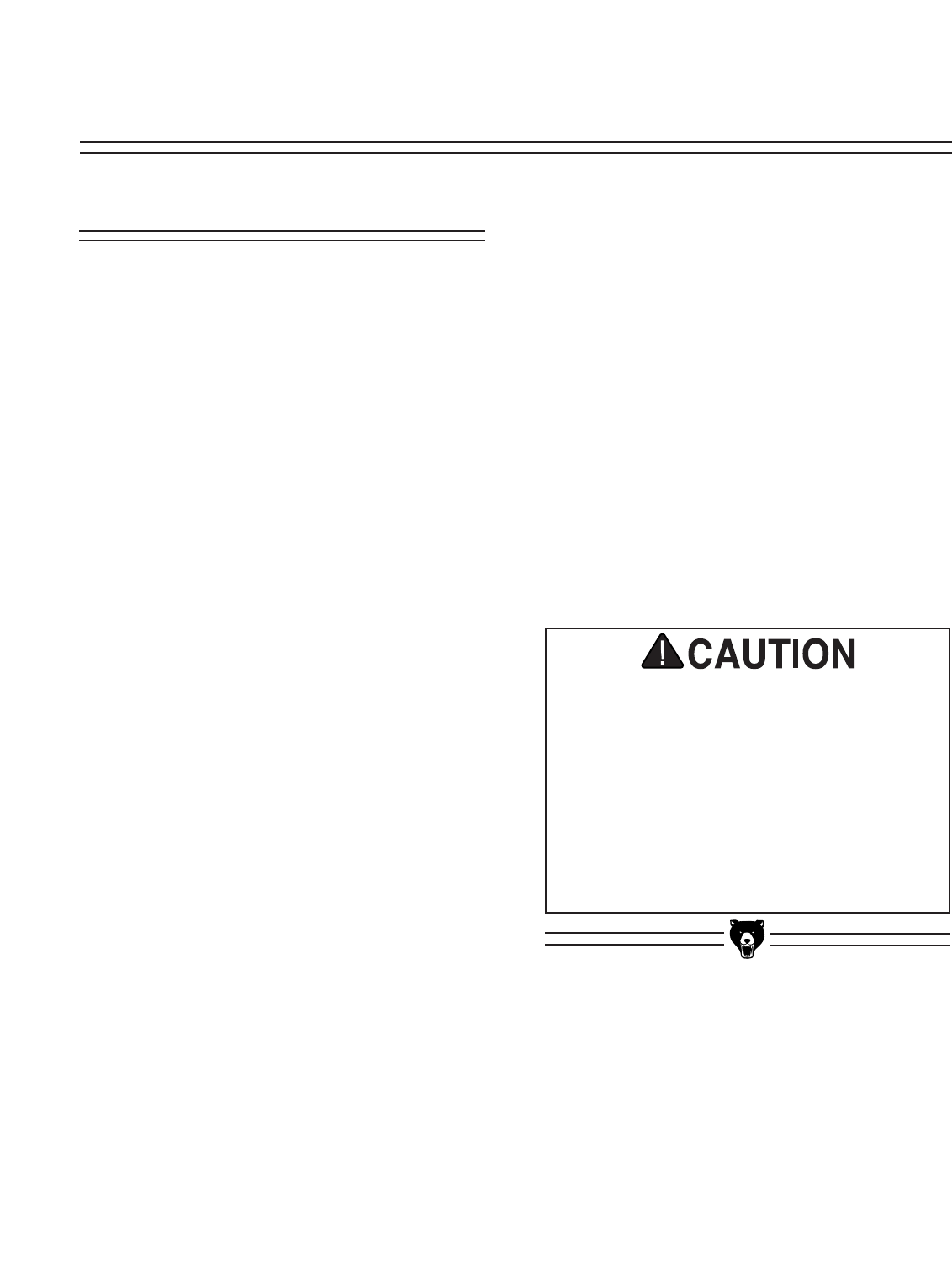
Many of the solvents commonly used to clean
machinery can be highly flammable, and toxic
when inhaled or ingested. Always work in well-
ventilated areas far from potential ignition
sources when dealing with solvents. Use care
when disposing of waste rags and towels to be
sure they do not create fire or environmental
hazards. Keep children and animals safely
away when cleaning and assembling this
machine.
Make your shop “child safe”. Ensure that your
workplace is inaccessible to youngsters by
closing and locking all entrances when you are
away. Never allow visitors in your shop when
assembling, adjusting or operating equipment.
-10- G5963 Surface Grinder
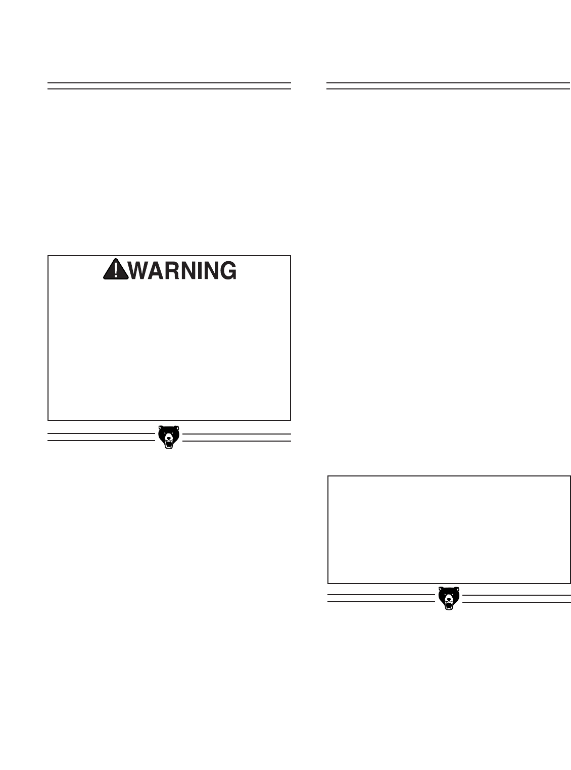
This surface grinder is heavy and awkward to
move. We recommend that you use the proper
equipment to put the surface grinder into posi-
tion in your shop or on a mobile base. Lifting
without proper equipment or ample assistance
could result in serious injury.
SECTION 4: ASSEMBLY
Lifting the Grinder
The majority of the weight of the Surface Grinder
is the grinding head. Take great care when lifting
this unit from the crate and moving it into position
on the stand. Remove the table from the crate
first and set it aside until the grinder is complete-
ly secured to the stand.
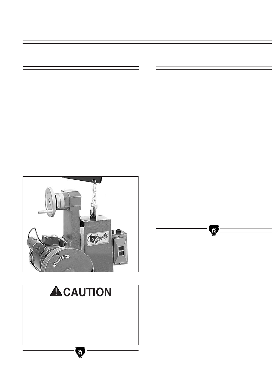
This grinding head unit is very heavy, approxi-
mately 400 lbs. There is a lifting eye on the top of
the upper unit which can be used with a chainfall
or hoist to lift the unit into position. See Figure 3.
Do not push on the upright sliding mechanism or
get it jammed in any way during movement. This
can damage the ways or the cross feed screw if
too much pressure is applied to the upright.
Mounting on Stand
Locate the stand as close to its final position as
possible. Position the grinding head on the stand,
lining up the four holes in the stand with the holes
in the base of the head. Use four hex bolts, wash-
ers and nuts provided to secure the head to the
stand.
Once the head is secured to the stand, loosen the
bolt on the back of the upright. This allows the
counterweight to move freely (it is locked into
position for shipping purposes). This bolt can be
completely removed or left in position should the
weight need to be locked for future movement.
With the stand in its final location, adjust the lev-
eling pads to bring the unit to a level position,
making sure there are no wobbles or vibration in
the assembly. In some cases, it may be useful to
bolt the unit to the floor, or to put vibration isola-
tion dampers underneath the feet of the stand to
avoid vibration. The more solid the mounting of
the unit is, the better the results that can be
achieved in the grinding process.
Figure 3. Lifting upper unit with chain hoist.
G5963 Surface Grinder -11-
Handwheel Handles
Table and Handwheel
There are two handwheels which control cross
feed and vertical movement. The handles for
these handwheels need to be threaded in the
hole in the outer edge of the wheel face.
Wipe the V-grooves of the table and the saddle
down with way oil (Mobil Vactra #2 or equivalent).
The table rests by its own weight on the ways,
and is oiled by the lubrication system. Set the
sliding table in position on the saddle. Make sure
the gear on the underside of the table engages
with the gear on the handwheel shaft.
Thread the three spokes of the handwheel onto
the hub, and tighten the jam nuts. Turn the hand-
wheel back and forth to make sure the table
moves freely.
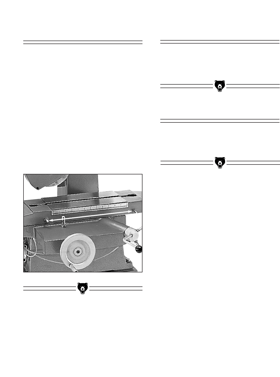
The table dogs should be in position to stop the
left and right movement of the table. Test these to
make sure the travel is limited so there is no
chance of moving the table too far in one direc-
tion. See Figure 4.
Guard
Attach the Guard to the left hand side of the table
using the socket head cap screws provided. This
guard helps to contain debris coming off the
rotating wheel during the grinding operation.
Figure 4. Table dogs limit table travel.
-12- G5963 Surface Grinder
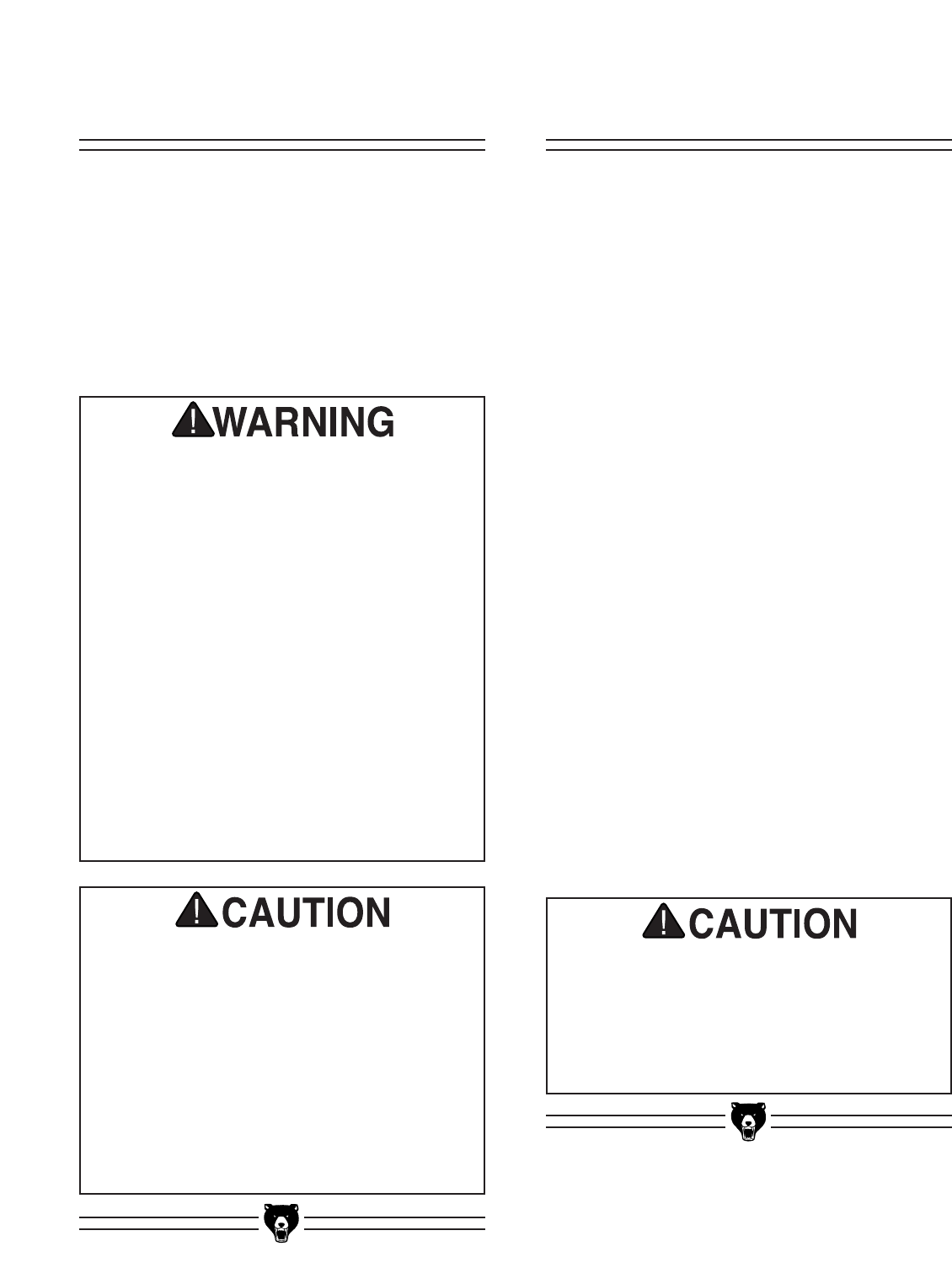
DO NOT make adjustments while the surface
grinder is running. Ensure that the switch is off,
power is disconnected and moving parts have
stopped before making adjustments. Failure to
comply could result in serious injury or electri-
cal shock hazard.
SECTION 5: OPERATIONS
Overview
Once assembly has been completed, the G5963
Surface Grinder is ready for use in the shop.
Many adjustments have already been made at
the factory, yet we recommend you familiarize
yourself with all of the following procedures to
gain a better understanding of the Surface
Grinder’s construction and operation.
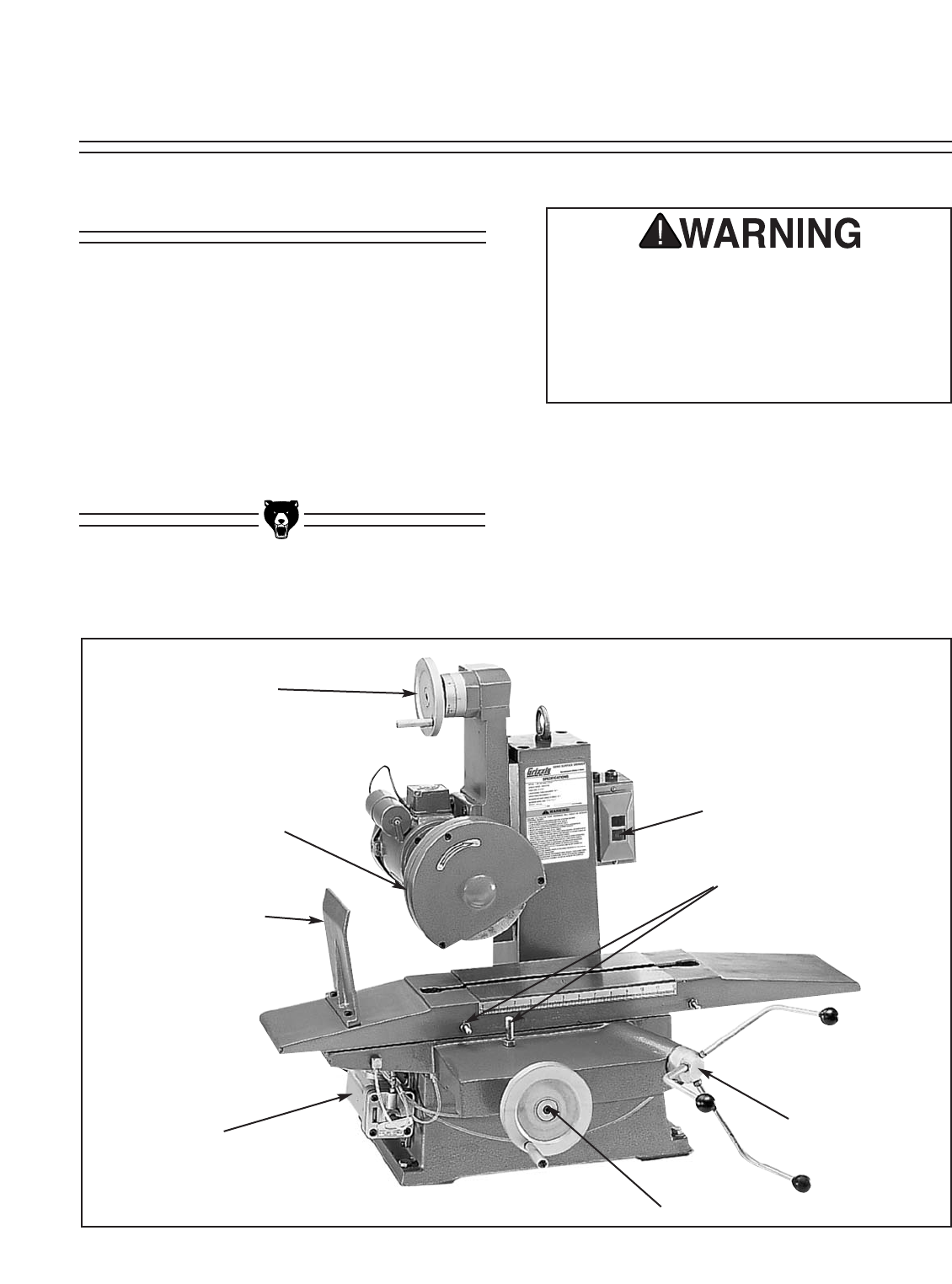
Control locations are shown in Figure 5.
ON/OFF Switch
Cross Feed Handwheel
Table Dogs
Table Travel
Handwheel
One-Shot
Lubricator
Guard
Grinding Wheel
Vertical Adjustment
Handwheel
Figure 5. Overview of surface grinder controls.
G5963 Surface Grinder -13-
Wheel Mounting
Before mounting any wheel, check it for integrity
by performing a “ring check”. Balance the wheel
on one finger, then lightly tap the rim of the wheel
with a piece of wood such as the handle of a
hammer. The wheel should have a ringing or har-
monic type of sound. If it responds with a dull
thud it may indicate that the wheel has cracks. Do
not use a wheel which is suspected of having
cracks, or if there are visual chips, nicks or dents
in the wheel surface. These discontinuities can
lead to wheel failure where the wheel flies apart
at operating speed. Always be sure to use a
wheel which is rated for operating at speeds of
3450 RPM.
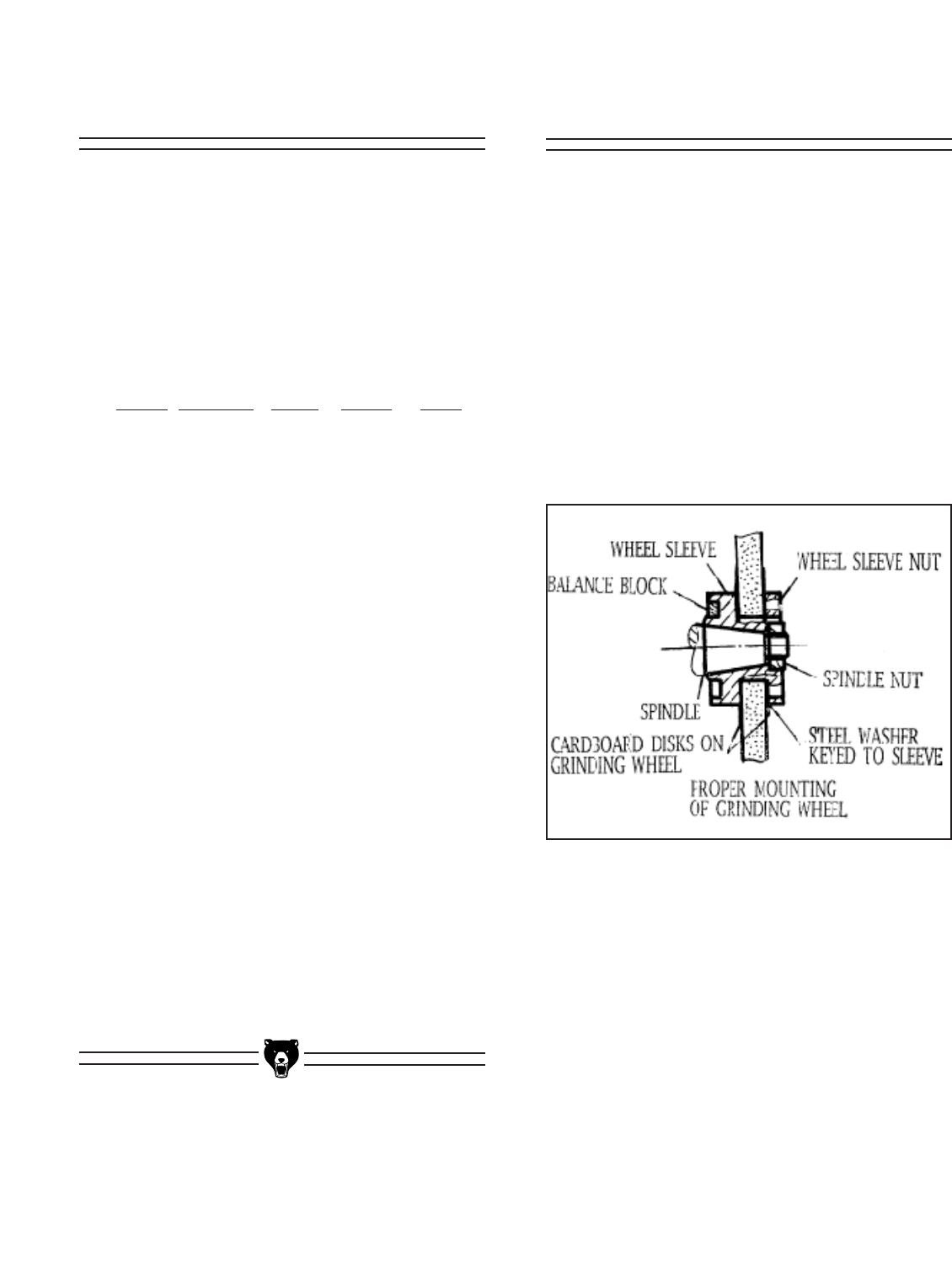
Figure 6. Cross-section of wheel assembly.
To mount the wheel (Refer to Figure 6):
1. Remove the wheel guard by unscrewing
the three cap screws holding the cover in
place.
2. With the Pin Wrench engaged in the two
holes on the face of the Wheel Sleeve Nut,
hold the spindle in position. Use the
Adjustable Wrench on the Spindle Nut and
loosen, keeping in mind that this is a left-
hand thread.
3. If the wheel does not pull easily off of the
taper, tap the end of the spindle lightly with
a wooden or rubber mallet to loosen the
wheel. Slide the wheel off of the taper.
Aluminum oxide and silicon carbide wheels are
marked in a somewhat uniform manner by all the
major manufacturers. Understanding these mark-
ings will help you understand the capabilities of
various wheels. Always refer to the manufactur-
er’s grinding recommendations when selecting a
wheel for your project.
The basic format for wheel numbering is:
Prefix Abrasive Grit Grade Bond
Type Size Type
36 A 60 L V
The most common abrasive types used are A for
Aluminum Oxide and C for Silicon Carbide, and
occasionally SG for seeded gel. The prefix is the
manufacturer’s designation for a particular type.
The grit size is a number referring to the size of
the abrasive grain in the wheel. The lower the
number the coarser the wheel - 10 is a very
coarse wheel for roughing and 220 is usually the
upper range for fine finish work.
Grade is an indication of the hardness of the
wheel, with A being softest to Z the hardest.
Bond Type refers to the type of bonding material
used to hold the abrasive material. Most general
purpose wheels will have a V indicating Vitrified
clay is used, providing a high strength and good
porosity. The other most common is B for resin
where synthetic resins are used. These are used
to grind cemented carbide and ceramic materials
There may be other numbers inserted which
have meaning for a particular type of wheel.
Refer to the manufacturer’s technical data for a
complete explanation.
Wheel Selection

-14- G5963 Surface Grinder
The wheel and sleeve assembly should be bal-
anced before mounting onto the Grinder.
Generally the wheel itself will be balanced by the
manufacturer. The Wheel Sleeve has Balance
Weights positioned in a groove which can be
moved to accomplish final balance of the assem-
bly.
1. Mount the wheel on the sleeve assembly
as described in the Wheel Mounting sec-
tion. Position the weights so they are even-
ly spaced around the groove.
2. Mount the wheel on the Balance Arbor,
which has a taper the same as that on the
machine spindle. Tighten the nut on the
arbor to lock the wheel in place.
3. Place the arbor across two parallel, level
bars so the wheel is freely suspended. The
wheel will turn until the heaviest side is
down. Mark the heavy side with a chalk
mark.
4. Loosen the setscrew on one of the Balance
Weights opposite the chalk mark, and
move it so it is 180˚ opposite the chalk
mark.
5. Place back on the bars and observe
whether one side is still heavy. It may be
necessary to repeat Steps 3 - 5 several
times until the wheel is balanced. When the
arbor does not roll across the bars at all,
then the wheel is in balance.
6. Remove the wheel from the Balance Arbor.
Make sure the Balance Weight setscrews
are firmly secured. Install wheel in the
grinder.
Make certain the wheel has a tight fit on the
Wheel Sleeve, and that the Sleeve Nut and
Spindle Nut are properly tightened on the
Spindle. Improper assembly of the grinding
wheel can cause failure of the wheel which can
result in a wheel breaking apart and causing
injury from flying debris. Always have the
Wheel Guard installed, even when test running
the machine.
4. Remove the Wheel Sleeve from the back
side of the wheel.
5. Take the new grinding wheel and insert the
Wheel Sleeve into the bore from the back of
the wheel. Most wheels will have a paper
disc on each side, this helps to equalize the
clamping pressure. Do not remove these
discs! The Wheel Sleeve should fit snugly
in the bore of the wheel. If it is too loose, do
not attempt to fill the gap with any other
types of material. The wheel will not main-
tain proper balance. If it is too tight, do not
attempt to force the wheel onto the Sleeve,
as it may cause cracking of the wheel.
6. Thread the Wheel Sleeve Nut onto the
opposite side of the wheel. Tighten enough
to get a good seat on the sleeves against
the paper discs, this helps to assure the
wheel will not slip in operation. Do not over-
tighten, however, as this can cause stress
on the wheel.
7. Slide this assembled wheel onto the spin-
dle, making sure the wheel sleeve hole and
the spindle taper are clean and free of any
foreign material, dents or nicks.
8. Tighten the Spindle Nut using the Pin
Wrench to hold the Sleeve and the
Adjustable Wrench to tighten the Nut. Do
not overtighten.
9. Replace the Wheel Guard and secure with
three cap screws.
10. Run the wheel at full speed for at least one
minute before doing any grinding. If there is
a structural problem with the wheel, it will
generally occur during the initial runup.
Wheel Balancing
G5963 Surface Grinder -15-
Dressing is performed on the face of the grinding
wheel to sharpen the abrasives or to remove
material which has imbedded in the surface.
Dressing also makes the circumference of the
wheel true to its centerpoint, thus insuring good
grinding results. Wheels should always be
dressed when first installed on the machine, and
also periodically as the wheel is used. The fre-
quency will depend upon the types of materials
being ground, and the severity of the grinding
operations. A wheel which will not balance prop-
erly may need to be dressed to true first to assure
concentricity.
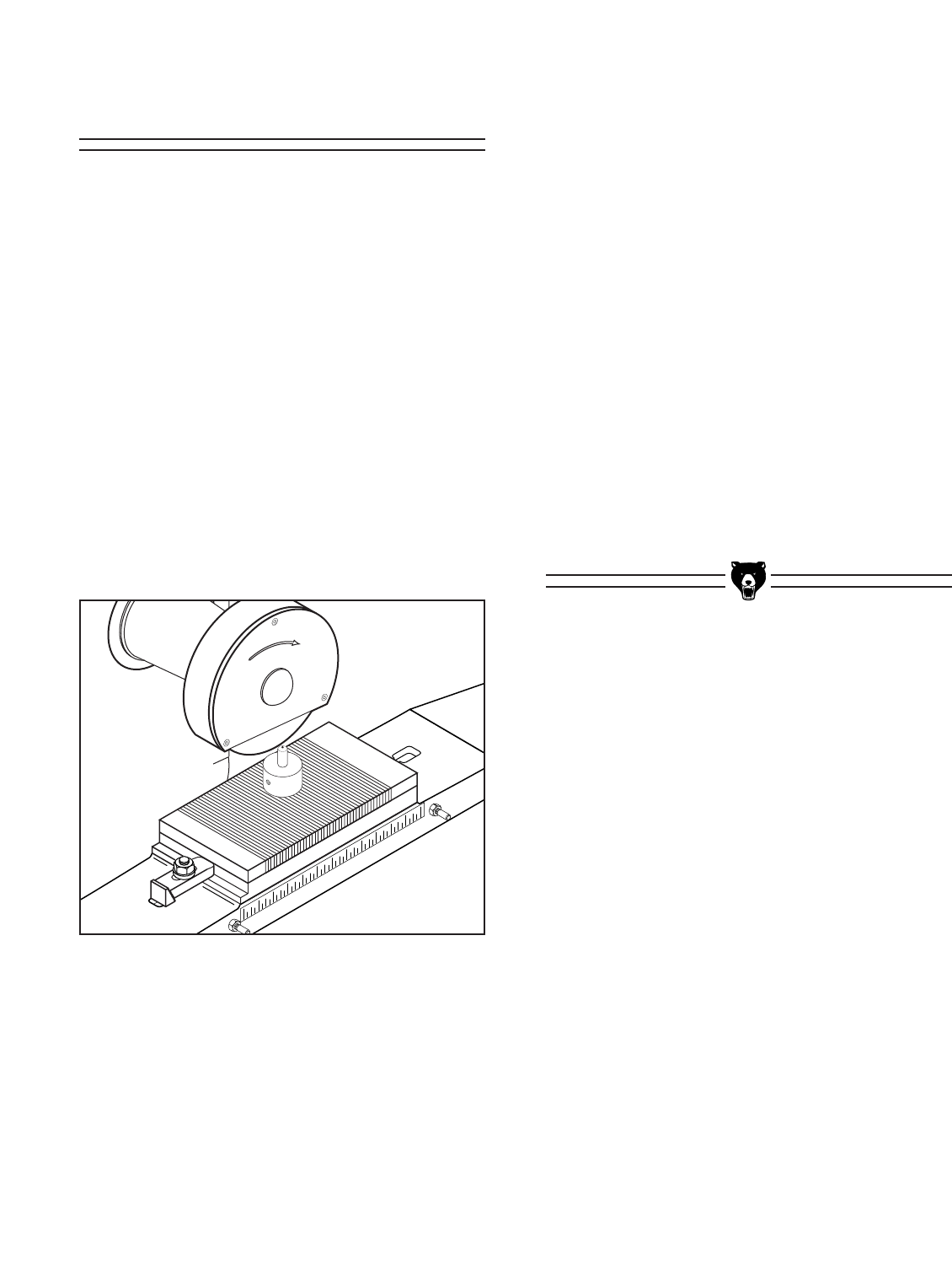
1. Insert the Dressing Diamond into the
Dressing Fixture and attach the fixture to
the table so that it is just right of the center
line of the grinding wheel. See Figure 7.
Figure 7. Dressing fixture mounted on magnetic chuck.
2. Lower the Vertical Adjustment Handwheel
so the grinding wheel just comes in contact
with the Dressing Diamond.
3. Move the Cross Feed Handwheel so the
Dresser is in front of the wheel. Make cer-
tain there is no movement of the
Longitudinal Handwheel during the dress-
ing operation.
4. Turn the grinder on and let the wheel spin
for at least one minute. Then advance the
Cross Feed so the Dresser sweeps across
the wheel. Lower the wheel .001" and
repeat. Continue successive passes until
the entire edge of the wheel is being cut. A
better finish will result if the last couple of
passes are less than .001".
5. Turn the machine off and remove the
Dressing Fixture.
Wheel Dressing
-16- G5963 Surface Grinder
NOTICE
If a cut is taken that is too large, the surface
grinder will bog down noticeably. The motor
may even stall. If this happens, turn off the
power immediately. Re-adjust the wheel height
to allow a lighter cut and repeat the operation.
Typical Operation
Operation of the grinder is controlled through the
location and movement of the three handwheels.
The Vertical Adjustment Handwheel controls the
up and down movement of the grinding head. It is
generally this axis which governs the amount of
stock removal which will take place. Never
attempt to remove too much material in one pass,
much better results can be achieved with multiple
passes.
The Cross Feed Handwheel controls the front to
back movement of the table. When grinding a
large surface, it will be necessary to sweep the
wheel over the surface, then move the table, then
take another sweep. Repeat this process until the
entire surface is ground. See Figure 9.
The Table Travel Handwheel (the one with the
three spokes) moves the table from left to right.
This allows the ability to traverse the part back
and forth underneath the grinding wheel.
Figure 9. Grinding multiple pieces.
DO NOT make adjustments while the surface
grinder is running. Ensure that the switch is off,
power is disconnected and moving parts have
stopped before making adjustments. Failure to
ensure that power is disconnected could result
in serious injury or electrical shock hazard.
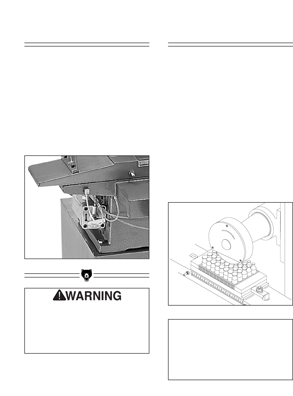
Figure 8. One-shot oil lubrication pump.
Oil Pump
The critical components of the machine are lubri-
cated by means of the oil pump located on the left
hand side of the machine. See Figure 8. Check
the oil level periodically. Add new oil (Use a Way
Oil such as Mobil Vactra #2 or equivalent) as
needed to maintain the fluid level in the Oil Pump.
Pull the handle of the Pump out. Do not attempt
to push it back in! The pump handle will slowly
return to its original position as the lubricant is
dispensed. Operate the Oil Pump at the start of
each day the grinder is used. The grinding wheel
does not need to be turned on for the Oil Pump to
work.
G5963 Surface Grinder -17-
Once the assembly is complete and the adjust-
ments are done to your satisfaction, you are
ready to test the machine.
Turn on the power supply at the main panel.
Press the START button. Make sure that your fin-
ger is poised on the STOP button, just in case
there is a problem. The surface grinder should
run smoothly, with little or no vibration or rubbing
noises. Strange or unnatural noises should be
investigated and corrected before operating the
machine further.
Test Run
NOTICE
Before starting any grinding job, run the sliding
table back and forth with the motor off! Check
to make sure there will be adequate clear-
ances between the wheel and the holding fix-
tures or portions of the part which are not
intended to be ground.
Operation of this equipment has the potential
to propel debris into the air which can cause
eye injury. Always wear safety glasses or gog-
gles when operating equipment. Everyday
glasses or reading glasses only have impact
resistant lenses, they are not safety glasses.
Be certain the safety glasses you wear meet
the appropriate standards of the American
National Standards Institute (ANSI).
Figure 10. Magnetic chuck mounted on table.
Accessories
In order to properly use this machine it is necessary to
purchase some type of holding fixture. The workpiece
must be firmly secured before beginning any type of
grinding operations. Refer to the current Grizzly cata-
log for options. The most versatile holding device is a
magnetic chuck. See Figure 10. With the throw of a
lever anything magnetic can be firmly attached to the
table without having jaws or fingers which might inter-
fere with the grinding wheel.
Some types of grinding will also be aided by the addi-
tion of some type of lubricant or coolant. These can be
introduced into the process by means of a spray device
operated by hand or by a pump of some sort. The
Grizzly catalog has several different options for adding
coolant capability to your grinder.
Figure 11. Magnetic V-Blocks for holding round stock
-18- G5963 Surface Grinder
SECTION 6: MAINTENANCE
Make a habit of inspecting your Surface Grinder
each time you use it. Check for the following con-
ditions and repair or replace when necessary:
1. Loose mounting bolts.
2. Worn switch.
3. Worn or damaged cords and plugs.
4. Damaged Grinding Wheel.
5. Any other condition that could hamper the
safe operation of this machine.
General Grinding Wheels
The grinding wheel should be inspected before
every use. Use the ring check method noted in
the Grinding Wheel section in Operations to veri-
fy the structural integrity. If using coolant during
grinding, always run the wheel for 5-10 minutes at
the end of the operation to remove any coolant
from the wheel. Take care in storing grinding
wheels to keep them free from potential damage
by being dropped, or having other items drop on
them.
Table
The table and other non-painted surfaces on the
Model G5963 should be protected against rust
and pitting. Wiping the table surface with a slight-
ly oily rag will protect bare metal surfaces from
moisture.
Periodically lift the sliding table off of the ways
and make sure the V-grooves and the helical
gear underneath are free of debris and metal
dust. Wipe the V-grooves of the table and the
saddle down with way oil (Mobil Vactra #2 or
equivalent) prior to reassembly.
Lubrication
Besides the one-shot lubrication system, the
Model G5963 features factory-sealed bearings. A
sealed bearing requires no lubrication during its
lifetime. Should a bearing fail, your surface
grinder will probably develop a noticeable rumble,
which will increase when the machine is put
under load. If allowed to get worse, overheating
of the journal containing the bad bearing could
occur. If the bad bearing is not replaced, it will
eventually seize - possibly doing damage to other
parts of the machine. Bearings are standard sizes
and can be replaced through Grizzly.
G5963 Surface Grinder -19-
The following pages contain parts diagrams, parts
lists, general machine data and warranty/return
information for your Model G5963 Surface
Grinder.
If you need parts or help in assembling your
machine, or if you need operational information,
we encourage you to call the Grizzly Industrial
Service Department. Our trained service techni-
cians will be glad to help you.
If you have comments dealing specifically with
this manual, please write to our Bellingham,
Washington location using the address in the
Introduction. The specifications, drawings, and
photographs illustrated in this manual represent
the Model G5963 as supplied when the manual
was prepared. However, due to Grizzly’s policy of
continuous improvement, changes may be made
at any time with no obligation on the part of
Grizzly. Whenever possible, though, we send
manual updates to all owners of a particular tool
or machine. Should you receive one, add the new
information to this manual and keep it for refer-
ence.
We have included some important safety mea-
sures that are essential to this machine’s opera-
tion. While most safety measures are generally
universal, Grizzly reminds you that each work-
shop is different and safety rules should be con-
sidered as they apply to your specific situation.
We recommend you keep a copy of our current
catalog for complete information regarding
Grizzly's warranty and return policy. If you need
additional technical information relating to this
machine, or if you need general assistance or
replacement parts, please contact the Service
Department listed in Section 3: GENERAL
INFORMATION.
Additional information sources are necessary to
realize the full potential of this machine. Trade
journals, woodworking magazines, and your local
library are good places to start.
SECTION 7: CLOSURE
The Model G5963 was specifically designed for
metal grinding operations. DO NOT MODIFY
AND/OR USE THIS SURFACE GRINDER
FOR ANY OTHER PURPOSE. Modifications or
improper use of this tool will void the warranty.
If you are confused about any aspect of this
machine, DO NOT use it until you have
answered all your questions. Serious injury
may occur.
Like all power tools, there is danger associated
with the Model G5963 Surface Grinder. Use
the tool with respect and caution to lessen the
possibility of mechanical damage or operator
injury. If normal safety precautions are over-
looked or ignored, serious injury may occur.
Always wear ANSI-approved safety glasses or
goggles and hearing protection when operating
equipment — particularly when testing new
tools or machinery. Do not allow visitors into
your workshop when testing or operating equip-
ment. Serious injury may occur.

-20- G5963 Surface Grinder
Customer Service #: (570) 326-3806 • To Order Call: (800) 523-4777 • Fax #: (800) 438-5901
MACHINE DATA
SHEET
Design Type ......................................................................................................Floor Model
Overall Dimensions:
Height ....................................................................................................................571⁄2''
Length ......................................................................................................................33''
Width ....................................................................................................................361⁄2''
Column Diameter........................................................................................................5''
Table Size ........................................................................................................6" x 12''
T-Slot and Size ................................................................................ 1⁄2'' Stud; 7⁄8" Head
Spindle Diameter ....................................................................................................11⁄4''
Shipping Weight ................................................................................................660 lbs.
Net Weight ........................................................................................................533 lbs.
Footprint ........................................................................................................20" x 20"
Capacity:
Max. Wheel Size ....................................................................................7" x 11⁄4'' x 1⁄2''
Max. Distance, Wheel to Table ..............................................................................87⁄8''
Longitudinal Travel ................................................................................................131⁄4''
Cross Travel ............................................................................................................71⁄8''
Spindle Speed (RPM) ............................................................................................3450
Construction ....................................................................................................Cast Iron
Motor:
Type ............................................................................TEFC Capacitor Start Induction
Horsepower ..........................................................................................................3⁄4HP
Phase ⁄ Voltage ..................................................................Single Phase; 110V ⁄ 220V
Amps ................................................................................................................7.4 ⁄ 3.7
Prewired ................................................................................................................110V
Cycle and RPM ....................................................................................60 Hertz ⁄ 3450
Bearings ..................................................................Shielded, Permanently Lubricated
Features:
....................................................................................................................Lubrication
..................................................................................................................Column Dial
............................................................................................................Cross Feed Dial
..............................................................................Heavy Gauge Sheet metal Cabinet
....................................................................................................One Shot Lubrication
.........................................................0.001" Graduations ⁄ Large Face Dial .50" ⁄ rev.
.....................................................0.001" Graduations ⁄ Medium face Dial .001" ⁄ rev.
..................................................................................................Power Indicator Lights
Accessories:
..................................................................................................Tool Box w⁄ Wrenches
..........................................................................................Grinding Stone Balance Kit
........................................................................................Dressing Diamond w ⁄ Mount
................................................................................................................Leveling Pads
..............................................................................................................Grinding Wheel
Specifications, while deemed accurate, are not guaranteed.
GRIZZLY MODEL G5963 MANUAL SURFACE GRINDER
REVISED 1/2000

G5963 Surface Grinder -21-
This section covers the most common processing problems encountered in grinding and what to do about
them. Do not make any adjustments until surface grinder is unplugged and moving parts have come to a
complete stop.
TROUBLESHOOTING
SYMPTOM
Motor will not start.
Motor will not start; fuses or
circuit breakers blow.
Motor overheats.
Motor stalls (resulting in
blown fuses or tripped cir-
cuit).
Machine slows when oper-
ating.
Wavy condition on surface
of workpiece.
Lines on surface of work-
piece.
Burning spots or cracks in
the workpiece.
Wheel dulls quickly, grit falls
off.
Wheel clogs and workpiece
shows burn marks.
POSSIBLE CAUSE
1. Low voltage.
2. Open circuit in motor or loose
connections.
1. Short circuit in line cord or plug.
2. Short circuit in motor or loose
connections.
3. Incorrect fuses or circuit break-
ers in power line.
1. Motor overloaded.
2. Air circulation through the motor
restricted.
1. Short circuit in motor or loose
connections.
2. Low voltage.
3. Incorrect fuses or circuit breakers
in power line.
4. Motor overloaded.
1. Feed rate too high.
2. Depth of cut too great.
1. Machine vibrating.
2. Grinding wheel not balanced.
3. Wheel is too hard.
4. Vertical slide loose.
1. Improper cross feed
2. Improper feed rate.
3. Impurity on wheel surface.
4. Workpiece not being held tightly.
1. Improper type of grinding wheel.
2. Improper feed rate.
3. Coolant required.
1. Depth of cut too great.
2. Feed rate too fast.
3. Wheel is too soft.
4. Bad wheel dress.
5. Defective wheel bonding.
1. Wheel is too hard.
2. Feed rate too slow.
3. Bad wheel dress.
4. Coolant required.
CORRECTIVE ACTION
1. Check power line for proper voltage.
2. Inspect all lead connections on motor for loose or open connec-
tions.
1. Inspect cord or plug for damaged insulation and shorted wires.
2. Inspect all connections on motor for loose or shorted terminals or
worn insulation.
3. Install correct fuses or circuit breakers.
1. Reduce load on motor.
2. Clean out motor to provide normal air circulation.
1. Inspect connections on motor for loose or shorted terminals or
worn insulation.
2Correct the low voltage conditions.
3. Install correct fuses or circuit breakers.
4. Reduce load on motor.
1. Slow down the rate of movement of the sliding table into wheel.
2. Reduce depth of cut by raising vertical adjustment.
1. Make sure machine is level and on a solid surface.
2. Balance the wheel.
3. Use softer wheel, or reduce the feed rate.
4. Adjust gibs on vertical slide.
1. Use smaller cross feed increments per wheel pass.
2. Vary the rate of movement of the sliding table into wheel.
3. Dress Wheel again
4. Check vice or chuck for tightness to the table.
1. Try a wheel which is soft or a coarser grit.
2. Slow down the rate of movement of the sliding table into wheel.
3. Add optional coolant system or introduce coolant by hand.
1. Raise wheel to reduce depth of cut.
2. Slow down the rate of movement of the sliding table into wheel.
3. Wheel too soft for the material being ground, select harder bond.
4. Dress the wheel.
5. Consult manufacturer of grinding wheel.
1. Wheel too hard for the material being ground, select softer bond.
2. Increase the rate of movement of the sliding table into wheel.
3. Dress the wheel.
4. Add optional coolant system or introduce coolant by hand.
-22- G5963 Surface Grinder
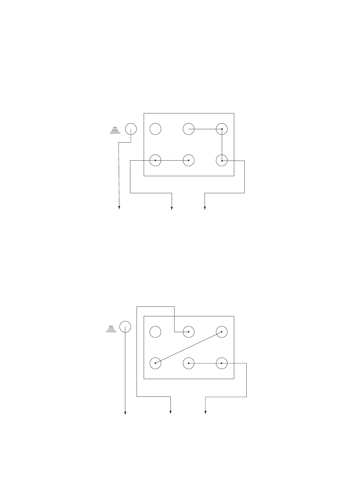
Z1 V1 U1
V2 U2 Z2
Z1 V1 U1
V2 U2 Z2
110 Volt Operation
220 Volt Operation
To Switch
To Switch
G5963 Surface Grinder
Wiring Diagram

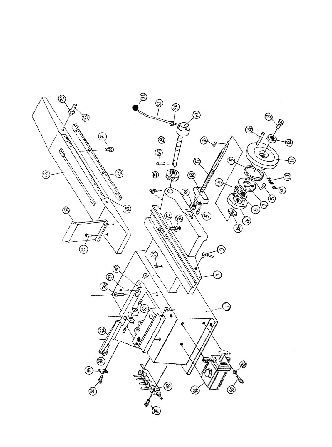
G5963 Surface Grinder -23-
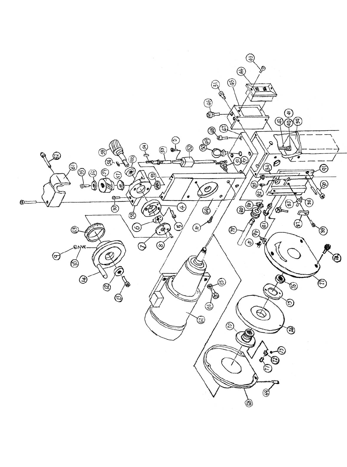
051 P5963051 ADJUSTMENT SCREW
052 P5963052 ELEVATION NUT
053 P5963053 ELEVATION LEAD SCREW
054 PK48M KEY 4 X 4 X 20
055 P5963055 BALL BEARING
056 P5963056 SEAT
057 P5963057 THRUST BEARING
058 P5963058 GEAR SHAFT
059 P5963059 GEAR
060 P5963060 WASHER
061 P5963061 COVER
062 P5963062 CAP SCREW M6- 1.0 x 55
063 P5963063 DIAL
064 P5963064 VERTICAL DOVETAIL BASE
065 PW04M FLAT WASHER 10MM
066 PB14M HEX BOLT M10-1.5 X 35
067 P5963067 3/4HP MOTOR
068 P5963068 REAR COVER
069 P5963069 HEX BOLT M8-1.25 X 10 W/CUP PT
070 P5963070 WHEEL SLEEVE
071 PSS02M SET SCREW M6-1 X 6
072 P5963072 BALANCE WEIGHT
073 P5963073 STEEL BALL 4MM
074 P5963074 GRINDING WHEEL 31.75 X 13
075 P5963075 WHEEL COLLAR
076 P5963076 MOUNTING NUT
077 P5963077 FRONT COVER
078 PSB06M CAP SCREW M6-1 X 25
079 P5963079 PULLEY SHAFT
080 P5963080 PULLEY
081 PB28M HEX BOLT M8-1.25 X 60
082 P5963082 HEX BOLT M8-1.25 X 20 W/CUP PT
083 P5963083 GIB SCREW
084 P5963084 GIB STRIP
085 P5963085 PULLEY
086 P5963086 ROLL PIN 6 X 45
087 P5963087 LOCKING TAB
088 PS05M PHLP HD SCR M5-.8 X 8
089 P5963089 OIL PIPE CLAMP
090 P5963090 CAP SCREW M10-1.25 X 14
091 P5963091 ELEVATION CARRIAGE
092 P5963092 GIB STRIP
093 P5963093 OIL MANIFOLD
094 P5963094 ONE SHOT 8CC OILER
095 PSB01M CAP SCREW M6-1.0 X 16
096 P5963096 SPRING LOCK WASHER
097 PSB50M CAP SCREW M5-.8 X 10
098 PN09M HEX NUT M12-1.75
099 P5963099 LIMIT TAB
100 P5963100 THRUST BEARING
Ref# Part# Description Ref# Part# Description
001 P5963001 BASE
002 P5963002 BASE W/ DOVETAIL GROOVE
003 P5963003 OIL PIPE ELBOW
004 P5963004 BEARING BLOCK
005 PSB24M CAP SCREW M5-.8 X 16
006 P5963006 BEARING 60202
007 P5963007 LOCKWASHER
008 PS09M PHLP HD SCR M5-.8 X 10
009 P5963009 STEEL BALL 6MM
010 P5963010 SPRING
011 P5963011 HANDWHEEL
012 P5963012 SCREW SEAT
013 PSB01M CAP SCREW M6-1.0 X 16
014 P5963014 HANDLE
015 P5963015 DIAL
016 PK37M KEY 4 X 4 X 16
017 P5963017 LONGITUDINAL FEED SCREW
018 P5963018 NUT, SPECIAL
019 P5963019 HANDLE HUB
020 PN03M HEX NUT M8-1.25
021 P5963020 LEVER
022 P5963022 GRIP
023 P5963023 CROSS FEED SHAFT
024 P5963024 TAPER PIN 5 X 30
025 P5963025 HELICAL GEAR, CROSS FEED
026 PN08M HEX NUT M10 - 1.25
027 P5963027 LIMIT PIN
028 P5963028 OIL CUP
029 P5963029 SCALE
030 P5963030 RACK
031 PSB26M CAP SCREW M6-1 X 12
032 P5963032 LIMIT PIN
033 P5963033 SLIDING TABLE
034 P5963034 GUARD
035 PSB02M CAP SCREW M6-1 X 20
036 P5963036 LONGITUDINAL FEED TABLE BASE
037 P5963037 TAPER PIN 6 X 40
038 P5963038 CAP SCREW M10-1.25 X 35
039 P5963039 COUNTERWEIGHT
040 P5963040 EYE BOLT
041 P5963041 CABLE CLIP
042 P5963042 STEEL CABLE 3MM
043 PS19M PHLP HD SCR M5-.8 X 6
044 P5963044 SWITCH 110/220V
045 P5963045 SWITCH BOX
046 P5963046 INDICATOR LIGHTS
047 P5963047 COVER
048 P5963048 CAP SCREW M10-1.25 X 25
049 PN13M HEX NUT M16-2.0
050 P5963050 EYE BOLT 16MM
-24- G5963 Surface Grinder
G5963 SURFACE GRINDER - LOWER ASSEMBLY
G5963 Surface Grinder -25-
G5963 SURFACE GRINDER - UPPER ASSEM-

-26- G5963 Surface Grinder
Grizzly Industrial, Inc. warrants every product it sells for a period of 1 year to the original purchaser from
the date of purchase. This warranty does not apply to defects due directly or indirectly to misuse, abuse,
negligence, accidents, repairs or alterations or lack of maintenance. This is Grizzly’s sole written warranty
and any and all warranties that may be implied by law, including any merchantability or fitness, for any par-
ticular purpose, are hereby limited to the duration of this written warranty. We do not warrant or represent
that the merchandise complies with the provisions of any law or acts unless the manufacturer so warrants.
In no event shall Grizzly’s liability under this warranty exceed the purchase price paid for the product and
any legal actions brought against Grizzly shall be tried in the State of Washington, County of Whatcom.
We shall in no event be liable for death, injuries to persons or property or for incidental, contingent, spe-
cial, or consequential damages arising from the use of our products.
To take advantage of this warranty, contact us by mail or phone and give us all the details. We will then
issue you a “Return Number’’, which must be clearly posted on the outside as well as the inside of the car-
ton. We will not accept any item back without this number. Proof of purchase must accompany the mer-
chandise.
The manufacturers reserve the right to change specifications at any time because they constantly strive to
achieve better quality equipment. We make every effort to ensure that our products meet high quality and
durability standards and we hope you never need to use this warranty.
Please feel free to write or call us if you have any questions about the machine or the manual.
Thank you again for your business and continued support. We hope to serve you again soon.
WARRANTY AND RETURNS

CUT ALONG DOTTED LINE
WARRANTY CARD
NAME_______________________________________________ PHONE NUMBER___________________
STREET________________________________________________________________________________
CITY_______________________________STATE_________ZIP ___________________________________
MODEL# _G5963 Surface Grinder_______________ INVOICE#_________________
The following information is given on a voluntary basis. This information will be used for marketing purposes to help
Grizzly develop better products. Your name will be included in our mailing list only. It will not be sold to other com-
panies. of course, all information is strictly confidential.
1. How did you find out about us?
__Advertisement __Friend __Website
__Catalog __Card deck __Other____________________
2. Do you think your machine represents good value? __YES __NO
3. Would you allow us to use your name as a reference for Grizzly customers in your area? __YES __NO
(Note: Your name will be used a maximum of three times.)
4. To which of the following publications do you subscribe? Check all that apply.
__Home Shop Machinist __Rifle Magazine Other ________________
__Projects in Metal __Hand Loader Magazine
__Modeltec __Precision Shooter
__Live Steam __RC Modeler
__Shotgun News __Model Airplane News
5. What is your annual household income?
__$20,000-$30,000 __$50,001-$60,000 __$80,000-$90,000
__$30,001-$40,000 __$60,001-$70,000 __+$90,000
__$40,001-$50,000 __$70,001-$80,000
6. To which age group do you belong?
__20-30 __41-50__61-70
__31-40 __51-60__+70
7. Which of the following machines or accessories do you own? Check all that apply.
__Engine Lathe __Abrasive Cutoff __Sheet Metal Machine
__Band Saw (Metal) __Arc Welder __Other _____________________________
__Band Saw (Wood) __Oxy/Ac. Outfit
__Milling Machine __Air Compressor
__Bench Grinder __Drill Press
8. How many of the machines you checked in Question 7 are Grizzly machines? ______________________
9. Which of the following tooling and accessories do you own? Check all that apply.
__Milling Vises __Collet Closer __Digital Readout
__Indexing Head __Taper Attachment __Tool Post Grinder
__Rotary Table __Boring Head __Other _________________________________________
10. In the space below, list three tools you would like Grizzly to carry.
11. Of all the mail order metalworking company’s you have purchased from, how do you rate Grizzly in terms of over-
all customer satisfaction?
__The best __Above average __Average
__Below average __The worst
12. Comments_______________________________________________________________________________
_____________________________________________________________________________________________
_____________________________________________________________________________________________
________________________________________________________________________________________________

FOLD ALONG DOTTED LINE
FOLD ALONG DOTTED LINE
GRIZZLY INDUSTRIAL, INC.
P.O. BOX 2069
BELLINGHAM, WA 98227-2069
Place
Stamp
Here
TAPE ALONG EDGES--PLEASE DO NOT STAPLE
Name_______________________________
Street_______________________________
City______________State______Zip______
Send a Grizzly Catalog to a friend:
